

HP StorageWorks XP12000, StorageWorks XP10000, StorageWorks SVS200 External Storage XP user guide
Page 1

HP StorageWorks
External Storage XP user guide
XP12000
XP10000
SVS200
Part number: T1706-96005
Fifth edition: June 2006
Page 2

Legal and notice information
© Copyright 2005, 2006 Hewlett-Packard Development Company, L.P.
Confidential computer software. Valid license from HP required for possession, use or copying. Consistent with FAR 12.211 and 12.212,
Commercial Computer Software, Computer Software Documentation, and Technical Data for Commercial Items are licensed to the U.S. Government
under vendor’s standard commercial license.
The information contained herein is subject to change without notice. The only warranties for HP products and services are set forth in the express
warranty statements accompanying such products and services. Nothing herein should be construed as constituting an additional warranty. HP shall
not be liable for technical or editorial errors or omissions contained herein.
Adobe® and Acrobat® are trademarks of Adobe Systems Incorporated.
z/OS is registered trademarks or trademarks of International Business Machines Corporation.
Microsoft, Windows, and Windows NT are registered trademarks or trademarks of Microsoft Corporation.
Netscape and Netscape Navigator are registered trademarks of Netscape Communications Corporation in the U.S. and other countries.
Java and all Java-based trademarks and logos are trademarks or registered trademarks of Sun Microsystems, Inc. in the United States and other
countries.
Solaris is a product name of Sun Microsystems, Inc.
External Storage XP user guide
Page 3

Contents
About this guide. . . . . . . . . . . . . . . . . . . . . . . . . . . . . . . . . . . . . . . . . . . . . . . . . . . . . . . 9
Supported storage platforms and firmware . . . . . . . . . . . . . . . . . . . . . . . . . . . . . . . . . . . . . . . . . . . . . . 9
Intended audience . . . . . . . . . . . . . . . . . . . . . . . . . . . . . . . . . . . . . . . . . . . . . . . . . . . . . . . . . . . . . . . 9
Prerequisites. . . . . . . . . . . . . . . . . . . . . . . . . . . . . . . . . . . . . . . . . . . . . . . . . . . . . . . . . . . . . . . . . . . . 9
Related documentation . . . . . . . . . . . . . . . . . . . . . . . . . . . . . . . . . . . . . . . . . . . . . . . . . . . . . . . . . . . . 9
Document conventions and symbols . . . . . . . . . . . . . . . . . . . . . . . . . . . . . . . . . . . . . . . . . . . . . . . . . . 10
HP technical support . . . . . . . . . . . . . . . . . . . . . . . . . . . . . . . . . . . . . . . . . . . . . . . . . . . . . . . . . . . . . 10
Subscription service . . . . . . . . . . . . . . . . . . . . . . . . . . . . . . . . . . . . . . . . . . . . . . . . . . . . . . . . . . . . . 10
HP web sites . . . . . . . . . . . . . . . . . . . . . . . . . . . . . . . . . . . . . . . . . . . . . . . . . . . . . . . . . . . . . . . . . . 11
Documentation feedback . . . . . . . . . . . . . . . . . . . . . . . . . . . . . . . . . . . . . . . . . . . . . . . . . . . . . . . . . . 11
1 Overview of connecting external arrays . . . . . . . . . . . . . . . . . . . . . . . . . . . . . . . . . . . 13
External Storage XP features . . . . . . . . . . . . . . . . . . . . . . . . . . . . . . . . . . . . . . . . . . . . . . . . . . . . . . . 13
2 Preparing for External Storage XP operations . . . . . . . . . . . . . . . . . . . . . . . . . . . . . . . . 15
System requirements . . . . . . . . . . . . . . . . . . . . . . . . . . . . . . . . . . . . . . . . . . . . . . . . . . . . . . . . . . . . . 15
Storage arrays that can be connected as external arrays . . . . . . . . . . . . . . . . . . . . . . . . . . . . . . . . . 15
External Storage XP requirements . . . . . . . . . . . . . . . . . . . . . . . . . . . . . . . . . . . . . . . . . . . . . . . . . . . . 19
Installing External Storage XP . . . . . . . . . . . . . . . . . . . . . . . . . . . . . . . . . . . . . . . . . . . . . . . . . . . . . . . 19
Preparing for External Storage XP settings . . . . . . . . . . . . . . . . . . . . . . . . . . . . . . . . . . . . . . . . . . . . . . 19
External ports . . . . . . . . . . . . . . . . . . . . . . . . . . . . . . . . . . . . . . . . . . . . . . . . . . . . . . . . . . . . . . . 20
External LU to be mapped. . . . . . . . . . . . . . . . . . . . . . . . . . . . . . . . . . . . . . . . . . . . . . . . . . . . . . . 20
External LU groups . . . . . . . . . . . . . . . . . . . . . . . . . . . . . . . . . . . . . . . . . . . . . . . . . . . . . . . . . . . . 20
External LU attributes set by mapping . . . . . . . . . . . . . . . . . . . . . . . . . . . . . . . . . . . . . . . . . . . . . . . 20
Alternate paths . . . . . . . . . . . . . . . . . . . . . . . . . . . . . . . . . . . . . . . . . . . . . . . . . . . . . . . . . . . . . . 22
Example of an alternate path configuration . . . . . . . . . . . . . . . . . . . . . . . . . . . . . . . . . . . . . . . . 22
Examples of switching I/O execution paths to alternate paths. . . . . . . . . . . . . . . . . . . . . . . . . . . . 23
Powering arrays on or off . . . . . . . . . . . . . . . . . . . . . . . . . . . . . . . . . . . . . . . . . . . . . . . . . . . . . . . . . 27
Powering local arrays on or off . . . . . . . . . . . . . . . . . . . . . . . . . . . . . . . . . . . . . . . . . . . . . . . . . . . 28
To power local arrays off . . . . . . . . . . . . . . . . . . . . . . . . . . . . . . . . . . . . . . . . . . . . . . . . . . . . . 28
To power local arrays on . . . . . . . . . . . . . . . . . . . . . . . . . . . . . . . . . . . . . . . . . . . . . . . . . . . . . 28
Powering external arrays on or off . . . . . . . . . . . . . . . . . . . . . . . . . . . . . . . . . . . . . . . . . . . . . . . . . 29
To power external arrays off . . . . . . . . . . . . . . . . . . . . . . . . . . . . . . . . . . . . . . . . . . . . . . . . . . 29
To power external arrays on . . . . . . . . . . . . . . . . . . . . . . . . . . . . . . . . . . . . . . . . . . . . . . . . . . 29
Using mapped external LUs from the host connected to the local array . . . . . . . . . . . . . . . . . . . . . . . . . . 29
Writing new data to mapped external LUs . . . . . . . . . . . . . . . . . . . . . . . . . . . . . . . . . . . . . . . . . . . 29
Using existing data in mapped external LUs . . . . . . . . . . . . . . . . . . . . . . . . . . . . . . . . . . . . . . . . . . 30
Uninstalling External Storage XP . . . . . . . . . . . . . . . . . . . . . . . . . . . . . . . . . . . . . . . . . . . . . . . . . . . . . 31
Limitations on External Storage XP operations. . . . . . . . . . . . . . . . . . . . . . . . . . . . . . . . . . . . . . . . . . . . 32
Combining External Storage XP with other HP StorageWorks products . . . . . . . . . . . . . . . . . . . . . . . . . . 37
Using external LUs for Auto LUN XP operations . . . . . . . . . . . . . . . . . . . . . . . . . . . . . . . . . . . . . . . . 38
Using external LUs for Continuous Access XP operations . . . . . . . . . . . . . . . . . . . . . . . . . . . . . . . . . . 39
Using external LUs for Continuous Access XP Journal operations . . . . . . . . . . . . . . . . . . . . . . . . . . . . 40
Using external LUs for Business Copy XP operations . . . . . . . . . . . . . . . . . . . . . . . . . . . . . . . . . . . . . 41
3 Managing cache with external storage . . . . . . . . . . . . . . . . . . . . . . . . . . . . . . . . . . . . 43
Guidelines for using cache with external storage . . . . . . . . . . . . . . . . . . . . . . . . . . . . . . . . . . . . . . . . . 43
Determining, setting, or changing the external LU cache mode . . . . . . . . . . . . . . . . . . . . . . . . . . . . . . . . 43
Determining if the cache mode is disabled . . . . . . . . . . . . . . . . . . . . . . . . . . . . . . . . . . . . . . . . . . . 44
Changing the cache mode . . . . . . . . . . . . . . . . . . . . . . . . . . . . . . . . . . . . . . . . . . . . . . . . . . . . . . 44
Collecting device information . . . . . . . . . . . . . . . . . . . . . . . . . . . . . . . . . . . . . . . . . . . . . . . . . . 44
Deleting and remapping the external LU . . . . . . . . . . . . . . . . . . . . . . . . . . . . . . . . . . . . . . . . . . 46
Partitioning cache for external storage . . . . . . . . . . . . . . . . . . . . . . . . . . . . . . . . . . . . . . . . . . . . . . . . 47
For example, Company A uses: . . . . . . . . . . . . . . . . . . . . . . . . . . . . . . . . . . . . . . . . . . . . . . 47
External Storage XP user guide 3
Page 4

In another example, Company B uses the following storage tiers: . . . . . . . . . . . . . . . . . . . . . . 47
To partition cache for external storage:. . . . . . . . . . . . . . . . . . . . . . . . . . . . . . . . . . . . . . . . . 47
Determining the number and size of needed partitions . . . . . . . . . . . . . . . . . . . . . . . . . . . . . . . . . . . . . 48
Creating Cache partitions . . . . . . . . . . . . . . . . . . . . . . . . . . . . . . . . . . . . . . . . . . . . . . . . . . . . . . . . . 48
Changing storage system modes . . . . . . . . . . . . . . . . . . . . . . . . . . . . . . . . . . . . . . . . . . . . . . . . . . . . 51
4 External Storage XP panes . . . . . . . . . . . . . . . . . . . . . . . . . . . . . . . . . . . . . . . . . . . . 53
LU Operation pane. . . . . . . . . . . . . . . . . . . . . . . . . . . . . . . . . . . . . . . . . . . . . . . . . . . . . . . . . . . . . . 54
Device tree . . . . . . . . . . . . . . . . . . . . . . . . . . . . . . . . . . . . . . . . . . . . . . . . . . . . . . . . . . . . . . . . . 55
Device list . . . . . . . . . . . . . . . . . . . . . . . . . . . . . . . . . . . . . . . . . . . . . . . . . . . . . . . . . . . . . . . . . . 56
WWN tree . . . . . . . . . . . . . . . . . . . . . . . . . . . . . . . . . . . . . . . . . . . . . . . . . . . . . . . . . . . . . . . . . 58
WWN list. . . . . . . . . . . . . . . . . . . . . . . . . . . . . . . . . . . . . . . . . . . . . . . . . . . . . . . . . . . . . . . . . . 59
Port tree . . . . . . . . . . . . . . . . . . . . . . . . . . . . . . . . . . . . . . . . . . . . . . . . . . . . . . . . . . . . . . . . . . . 61
Port list . . . . . . . . . . . . . . . . . . . . . . . . . . . . . . . . . . . . . . . . . . . . . . . . . . . . . . . . . . . . . . . . . . . . 61
Filter button. . . . . . . . . . . . . . . . . . . . . . . . . . . . . . . . . . . . . . . . . . . . . . . . . . . . . . . . . . . . . . . . . 63
Preset list (LU Operation pane) . . . . . . . . . . . . . . . . . . . . . . . . . . . . . . . . . . . . . . . . . . . . . . . . . . . 63
Port Operation pane . . . . . . . . . . . . . . . . . . . . . . . . . . . . . . . . . . . . . . . . . . . . . . . . . . . . . . . . . . . . . 64
Port Operation tree . . . . . . . . . . . . . . . . . . . . . . . . . . . . . . . . . . . . . . . . . . . . . . . . . . . . . . . . . . . 65
Port Operation list . . . . . . . . . . . . . . . . . . . . . . . . . . . . . . . . . . . . . . . . . . . . . . . . . . . . . . . . . . . . 66
Preset list (Port Operation pane) . . . . . . . . . . . . . . . . . . . . . . . . . . . . . . . . . . . . . . . . . . . . . . . . . . 66
5 Configuring external LUs . . . . . . . . . . . . . . . . . . . . . . . . . . . . . . . . . . . . . . . . . . . . . 69
Overview of configuring external LUs . . . . . . . . . . . . . . . . . . . . . . . . . . . . . . . . . . . . . . . . . . . . . . . . . 69
Setting an external array’s port . . . . . . . . . . . . . . . . . . . . . . . . . . . . . . . . . . . . . . . . . . . . . . . . . . . . . 70
Setting a local array’s port attributes . . . . . . . . . . . . . . . . . . . . . . . . . . . . . . . . . . . . . . . . . . . . . . . . . . 70
Mapping external LUs (Add LU) . . . . . . . . . . . . . . . . . . . . . . . . . . . . . . . . . . . . . . . . . . . . . . . . . . . . . 70
Mapping external LUs individually (Add LU) . . . . . . . . . . . . . . . . . . . . . . . . . . . . . . . . . . . . . . . . . . 71
Select Paths pane . . . . . . . . . . . . . . . . . . . . . . . . . . . . . . . . . . . . . . . . . . . . . . . . . . . . . . . . . . 74
Mapping multiple external LUs at one time (Add LU (Auto)) . . . . . . . . . . . . . . . . . . . . . . . . . . . . . . . . 78
Select LDEV window . . . . . . . . . . . . . . . . . . . . . . . . . . . . . . . . . . . . . . . . . . . . . . . . . . . . . . . . 81
Displaying detailed information stored in VMA (VMA information). . . . . . . . . . . . . . . . . . . . . . . . . . . 83
Setting alternate paths for external LUs . . . . . . . . . . . . . . . . . . . . . . . . . . . . . . . . . . . . . . . . . . . . . . . . 84
Defining alternate paths . . . . . . . . . . . . . . . . . . . . . . . . . . . . . . . . . . . . . . . . . . . . . . . . . . . . . . . . 87
Changing a defined alternate path priority . . . . . . . . . . . . . . . . . . . . . . . . . . . . . . . . . . . . . . . . . . . 87
Canceling alternate path definitions . . . . . . . . . . . . . . . . . . . . . . . . . . . . . . . . . . . . . . . . . . . . . . . . 88
Changing alternate paths . . . . . . . . . . . . . . . . . . . . . . . . . . . . . . . . . . . . . . . . . . . . . . . . . . . . . . . 88
Adding alternate paths by selecting multiple external LUs (Add Paths) . . . . . . . . . . . . . . . . . . . . . . . . . . . 89
Deleting alternate paths by selecting multiple external LUs (Delete Paths) . . . . . . . . . . . . . . . . . . . . . . . . . 90
Checking an external LU’s status (LDEV Information) . . . . . . . . . . . . . . . . . . . . . . . . . . . . . . . . . . . . . . . 92
Obtaining information about external LUs . . . . . . . . . . . . . . . . . . . . . . . . . . . . . . . . . . . . . . . . . . . . 92
Restoring external LUs (Restore) . . . . . . . . . . . . . . . . . . . . . . . . . . . . . . . . . . . . . . . . . . . . . . . . . . . 93
Displaying configuration information for external LUs (Volume Detail). . . . . . . . . . . . . . . . . . . . . . . . . 94
Disconnecting external arrays or LUs. . . . . . . . . . . . . . . . . . . . . . . . . . . . . . . . . . . . . . . . . . . . . . . . . . 95
Disconnecting all external LUs in an external array (Disconnect Subsystem). . . . . . . . . . . . . . . . . . . . . 96
Disconnecting external LUs individually (Disconnect Volume) . . . . . . . . . . . . . . . . . . . . . . . . . . . . . . . 96
Checking the connection status and resuming external LU operations (Check Paths & Restore Vol.) . . . . . . . 97
Restoring all external LUs in an external array (Check Paths & Restore Vol.) . . . . . . . . . . . . . . . . . . . . 97
Restoring external LUs individually (Check Paths & Restore Vol.) . . . . . . . . . . . . . . . . . . . . . . . . . . . . 98
Restoring external LUs (LDEV Restore) . . . . . . . . . . . . . . . . . . . . . . . . . . . . . . . . . . . . . . . . . . . . . . . . . 98
Restoring volumes in an external array . . . . . . . . . . . . . . . . . . . . . . . . . . . . . . . . . . . . . . . . . . . . . . 98
Restoring volumes in a mapped external LU individually . . . . . . . . . . . . . . . . . . . . . . . . . . . . . . . . . . 98
Stopping the use of paths to an external LU by specifying an external array’s WWN (Disconnect Paths) . . . 99
Restoring paths to an external LU by specifying an external array’s WWN (Check Paths) . . . . . . . . . . . . . 99
Changing an external array’s port setting . . . . . . . . . . . . . . . . . . . . . . . . . . . . . . . . . . . . . . . . . . . . . 100
Stopping the use of paths to an external LU by specifying a local array’s port (Disconnect Paths) . . . . . . . 101
Restoring paths to an external LU by specifying a local array’s port (Check Paths) . . . . . . . . . . . . . . . . . 101
Deleting external LU mappings (Delete LU). . . . . . . . . . . . . . . . . . . . . . . . . . . . . . . . . . . . . . . . . . . . . 101
6 Remote command devices . . . . . . . . . . . . . . . . . . . . . . . . . . . . . . . . . . . . . . . . . . . 103
Overview of remote command devices . . . . . . . . . . . . . . . . . . . . . . . . . . . . . . . . . . . . . . . . . . . . . . . 103
4
Page 5

Notices about remote command devices . . . . . . . . . . . . . . . . . . . . . . . . . . . . . . . . . . . . . . . . . . . . . . 103
Mapping command devices as remote command devices . . . . . . . . . . . . . . . . . . . . . . . . . . . . . . . . . . 105
7 Troubleshooting External Storage XP . . . . . . . . . . . . . . . . . . . . . . . . . . . . . . . . . . . . . 107
A Notes on connecting external arrays. . . . . . . . . . . . . . . . . . . . . . . . . . . . . . . . . . . . . 113
Connecting Thunder 9500V subsystems . . . . . . . . . . . . . . . . . . . . . . . . . . . . . . . . . . . . . . . . . . . . . . 113
System parameters for connecting Thunder 9500V subsystems . . . . . . . . . . . . . . . . . . . . . . . . . . . . 113
Relationship between serial numbers in the Device list on the LU Operation pane and Thunder
9500V subsystem models . . . . . . . . . . . . . . . . . . . . . . . . . . . . . . . . . . . . . . . . . . . . . . . . . . . . . . 115
Relationship between the WWN of the port on the Thunder 9500V subsystem and the controller . . . . 115
Path status and examples of recovery procedures (Thunder 9500V subsystems) . . . . . . . . . . . . . . . . . 116
Connecting TagmaStore AMS and TagmaStore WMS subsystems . . . . . . . . . . . . . . . . . . . . . . . . . . . . 117
System parameters for connecting TagmaStore AMS and TagmaStore WMS subsystems . . . . . . . . . . 117
Relationship between serial numbers in the Device list on the LU Operation pane and TagmaStore
AMS and TagmaStore WMS subsystem models. . . . . . . . . . . . . . . . . . . . . . . . . . . . . . . . . . . . . . . 118
Relationship between the WWN of the port on the TagmaStore AMS or TagmaStore WMS
subsystem and the controller . . . . . . . . . . . . . . . . . . . . . . . . . . . . . . . . . . . . . . . . . . . . . . . . . . . . 118
Path status and examples of recovery procedures (TagmaStore AMS and TagmaStore WMS
subsystems) . . . . . . . . . . . . . . . . . . . . . . . . . . . . . . . . . . . . . . . . . . . . . . . . . . . . . . . . . . . . . . . . 119
Connecting XP12000/XP10000 Disk Arrays . . . . . . . . . . . . . . . . . . . . . . . . . . . . . . . . . . . . . . . . . . . 120
Path status and examples of recovery procedures (XP12000/XP10000 Disk Arrays) . . . . . . . . . . . . . 120
Connecting XP1024/XP128 Disk Arrays . . . . . . . . . . . . . . . . . . . . . . . . . . . . . . . . . . . . . . . . . . . . . . 121
Path status and examples of recovery procedures (XP1024/XP128 Disk Arrays) . . . . . . . . . . . . . . . . 121
Connecting XP512/XP48 Disk Arrays . . . . . . . . . . . . . . . . . . . . . . . . . . . . . . . . . . . . . . . . . . . . . . . . 122
Path status and examples of recovery procedures (XP512/XP48 Disk Arrays) . . . . . . . . . . . . . . . . . . 122
Connecting HP 200 Storage Virtualization System as external storage . . . . . . . . . . . . . . . . . . . . . . . . . 123
Path status and examples of recovery procedures (SVS200) . . . . . . . . . . . . . . . . . . . . . . . . . . . . . . 124
Connecting EVA arrays . . . . . . . . . . . . . . . . . . . . . . . . . . . . . . . . . . . . . . . . . . . . . . . . . . . . . . . . . . 124
Identifying logical volumes of EVA arrays (using Characteristic 2) . . . . . . . . . . . . . . . . . . . . . . . . . . 124
Alternate path’s behavior when an EVA array is connected . . . . . . . . . . . . . . . . . . . . . . . . . . . . . . 125
B Required volume capacity for emulation types . . . . . . . . . . . . . . . . . . . . . . . . . . . . . . 127
C Adjusting volume capacity for copy pair setting . . . . . . . . . . . . . . . . . . . . . . . . . . . . . 131
Copying data from external arrays (using external LUs as P-VOLs) . . . . . . . . . . . . . . . . . . . . . . . . . . . . 131
Copying data to external arrays (setting external LUs as S-VOLs) . . . . . . . . . . . . . . . . . . . . . . . . . . . . . 131
D Using an XP12000/XP10000/SVS200 with an EVA3000/5000 external storage . . . . 133
Preface . . . . . . . . . . . . . . . . . . . . . . . . . . . . . . . . . . . . . . . . . . . . . . . . . . . . . . . . . . . . . . . . . . . . . 133
Configuration. . . . . . . . . . . . . . . . . . . . . . . . . . . . . . . . . . . . . . . . . . . . . . . . . . . . . . . . . . . . . . . . . 133
Physical array connections . . . . . . . . . . . . . . . . . . . . . . . . . . . . . . . . . . . . . . . . . . . . . . . . . . . . . 133
Minimum physical configuration for HA . . . . . . . . . . . . . . . . . . . . . . . . . . . . . . . . . . . . . . . . . . 133
Expanded configuration. . . . . . . . . . . . . . . . . . . . . . . . . . . . . . . . . . . . . . . . . . . . . . . . . . . . . 134
Creating new EVA host objects for the XP12000/XP10000/SVS200 . . . . . . . . . . . . . . . . . . . . . . . 134
Creating and presenting EVA Vdisks . . . . . . . . . . . . . . . . . . . . . . . . . . . . . . . . . . . . . . . . . . . . . . 135
Defining XP12000/XP10000/SVS200 external ports . . . . . . . . . . . . . . . . . . . . . . . . . . . . . . . . . . 136
Defining XP12000/XP10000/SVS200 external storage LDEVs . . . . . . . . . . . . . . . . . . . . . . . . . . . . 137
Recommendations. . . . . . . . . . . . . . . . . . . . . . . . . . . . . . . . . . . . . . . . . . . . . . . . . . . . . . . . . . . . . . 139
Performance considerations for using EVAs as external storage . . . . . . . . . . . . . . . . . . . . . . . . . . . . 139
Defining alternate paths . . . . . . . . . . . . . . . . . . . . . . . . . . . . . . . . . . . . . . . . . . . . . . . . . . . . . . . 139
Troubleshooting . . . . . . . . . . . . . . . . . . . . . . . . . . . . . . . . . . . . . . . . . . . . . . . . . . . . . . . . . . . . . . . 140
E Configuring MSA1000/1500 as external arrays . . . . . . . . . . . . . . . . . . . . . . . . . . . . 141
Configuring external array LUs, host mode, and ports . . . . . . . . . . . . . . . . . . . . . . . . . . . . . . . . . . . . . 141
Connecting MSA1000/1500 . . . . . . . . . . . . . . . . . . . . . . . . . . . . . . . . . . . . . . . . . . . . . . . . . . . . . 141
Setting up the MSA. . . . . . . . . . . . . . . . . . . . . . . . . . . . . . . . . . . . . . . . . . . . . . . . . . . . . . . . . . . . . 142
Defining MSA array objects . . . . . . . . . . . . . . . . . . . . . . . . . . . . . . . . . . . . . . . . . . . . . . . . . . . . . . . 142
Calculating MSA LU size and defining LUs . . . . . . . . . . . . . . . . . . . . . . . . . . . . . . . . . . . . . . . . . . . . 142
Selective Storage Presentation . . . . . . . . . . . . . . . . . . . . . . . . . . . . . . . . . . . . . . . . . . . . . . . . . . . . . 143
External Storage XP user guide 5
Page 6

Index . . . . . . . . . . . . . . . . . . . . . . . . . . . . . . . . . . . . . . . . . . . . . . . . . . . . . . . . . . . . 145
Figures
1 External Storage XP concept . . . . . . . . . . . . . . . . . . . . . . . . . . . . . . . . . . . . . . . . . . . . . . . . . . . . 14
2 Example of alternate path configuration . . . . . . . . . . . . . . . . . . . . . . . . . . . . . . . . . . . . . . . . . . . . 23
3 Example of alternate path configuration using two switches . . . . . . . . . . . . . . . . . . . . . . . . . . . . . . 23
4 Example of incorrect alternate path configurations . . . . . . . . . . . . . . . . . . . . . . . . . . . . . . . . . . . . . 23
5 Alternate path mode is Multi mode . . . . . . . . . . . . . . . . . . . . . . . . . . . . . . . . . . . . . . . . . . . . . . . 24
6 Alternate path mode is Single mode. . . . . . . . . . . . . . . . . . . . . . . . . . . . . . . . . . . . . . . . . . . . . . . 25
7 Alternate path mode is Single mode with alternate paths in Normal and Standby . . . . . . . . . . . . . . . 26
8 Alternate path mode is Single mode with alternate paths in Standby only . . . . . . . . . . . . . . . . . . . . . 27
9 Writing new data to mapped external LUs . . . . . . . . . . . . . . . . . . . . . . . . . . . . . . . . . . . . . . . . . . 30
10 Using existing data in mapped external LUs (without formatting) . . . . . . . . . . . . . . . . . . . . . . . . . . . 31
11 Example of external LU with 2 TB or less. . . . . . . . . . . . . . . . . . . . . . . . . . . . . . . . . . . . . . . . . . . . 32
12 External LU capacity is larger than the specified emulation type’s basic capacity (OPEN-3 example) . . 33
13 External LU capacity is smaller than the specified emulation type’s basic capacity . . . . . . . . . . . . . . . 33
14 Example of Auto LUN XP operations . . . . . . . . . . . . . . . . . . . . . . . . . . . . . . . . . . . . . . . . . . . . . . 39
15 Example of Continuous Access XP operations . . . . . . . . . . . . . . . . . . . . . . . . . . . . . . . . . . . . . . . . 40
16 Example of Continuous Access XP Journal operations . . . . . . . . . . . . . . . . . . . . . . . . . . . . . . . . . . . 41
17 Example of Business Copy operations . . . . . . . . . . . . . . . . . . . . . . . . . . . . . . . . . . . . . . . . . . . . . 42
18 LU Operation pane, Cache Mode setting . . . . . . . . . . . . . . . . . . . . . . . . . . . . . . . . . . . . . . . . . . . 44
19 LU Operation pane, LU number and UUID . . . . . . . . . . . . . . . . . . . . . . . . . . . . . . . . . . . . . . . . . . 45
20 LU Operation pane, Path Setting option . . . . . . . . . . . . . . . . . . . . . . . . . . . . . . . . . . . . . . . . . . . . 45
21 Path Setting pane . . . . . . . . . . . . . . . . . . . . . . . . . . . . . . . . . . . . . . . . . . . . . . . . . . . . . . . . . . . 46
22 LDEV Information pane. . . . . . . . . . . . . . . . . . . . . . . . . . . . . . . . . . . . . . . . . . . . . . . . . . . . . . . . 46
23 Partition Definition pane . . . . . . . . . . . . . . . . . . . . . . . . . . . . . . . . . . . . . . . . . . . . . . . . . . . . . . . 49
24 Partition Definition pane, Cut option. . . . . . . . . . . . . . . . . . . . . . . . . . . . . . . . . . . . . . . . . . . . . . . 50
25 Partition Definition pane, Paste Parity Group option . . . . . . . . . . . . . . . . . . . . . . . . . . . . . . . . . . . . 50
26 Panes for External Storage XP operations . . . . . . . . . . . . . . . . . . . . . . . . . . . . . . . . . . . . . . . . . . . 53
27 LU Operation pane . . . . . . . . . . . . . . . . . . . . . . . . . . . . . . . . . . . . . . . . . . . . . . . . . . . . . . . . . . 54
28 Device tree . . . . . . . . . . . . . . . . . . . . . . . . . . . . . . . . . . . . . . . . . . . . . . . . . . . . . . . . . . . . . . . . 55
29 Device list (external device selected in Device tree) . . . . . . . . . . . . . . . . . . . . . . . . . . . . . . . . . . . . 56
30 WWN tree . . . . . . . . . . . . . . . . . . . . . . . . . . . . . . . . . . . . . . . . . . . . . . . . . . . . . . . . . . . . . . . . 58
31 WWN list (External Devices selected in the WWN tree). . . . . . . . . . . . . . . . . . . . . . . . . . . . . . . . . 59
32 Port tree . . . . . . . . . . . . . . . . . . . . . . . . . . . . . . . . . . . . . . . . . . . . . . . . . . . . . . . . . . . . . . . . . . 61
33 Port list (External selected in Port tree). . . . . . . . . . . . . . . . . . . . . . . . . . . . . . . . . . . . . . . . . . . . . . 61
34 Filter window . . . . . . . . . . . . . . . . . . . . . . . . . . . . . . . . . . . . . . . . . . . . . . . . . . . . . . . . . . . . . . 63
35 Preset Detail window (mapping operation) . . . . . . . . . . . . . . . . . . . . . . . . . . . . . . . . . . . . . . . . . . 64
36 Port Operation pane . . . . . . . . . . . . . . . . . . . . . . . . . . . . . . . . . . . . . . . . . . . . . . . . . . . . . . . . . 64
37 Port Operation tree . . . . . . . . . . . . . . . . . . . . . . . . . . . . . . . . . . . . . . . . . . . . . . . . . . . . . . . . . . 65
38 Port Operation list . . . . . . . . . . . . . . . . . . . . . . . . . . . . . . . . . . . . . . . . . . . . . . . . . . . . . . . . . . . 66
39 Preset Detail window (changing port attribute). . . . . . . . . . . . . . . . . . . . . . . . . . . . . . . . . . . . . . . . 67
40 Overview of configuring external LUs . . . . . . . . . . . . . . . . . . . . . . . . . . . . . . . . . . . . . . . . . . . . . . 69
41 Add LU window . . . . . . . . . . . . . . . . . . . . . . . . . . . . . . . . . . . . . . . . . . . . . . . . . . . . . . . . . . . . 71
42 Select Paths pane . . . . . . . . . . . . . . . . . . . . . . . . . . . . . . . . . . . . . . . . . . . . . . . . . . . . . . . . . . . 74
43 Add LU pane (mapping using the Linear button) . . . . . . . . . . . . . . . . . . . . . . . . . . . . . . . . . . . . . . 76
44 Add LU pane (mapping with the Linear button released . . . . . . . . . . . . . . . . . . . . . . . . . . . . . . . . . 76
45 SSID window . . . . . . . . . . . . . . . . . . . . . . . . . . . . . . . . . . . . . . . . . . . . . . . . . . . . . . . . . . . . . . 77
46 Set SSID window . . . . . . . . . . . . . . . . . . . . . . . . . . . . . . . . . . . . . . . . . . . . . . . . . . . . . . . . . . . . 77
47 Auto Map Setting window . . . . . . . . . . . . . . . . . . . . . . . . . . . . . . . . . . . . . . . . . . . . . . . . . . . . . 78
48 Select LDEV window . . . . . . . . . . . . . . . . . . . . . . . . . . . . . . . . . . . . . . . . . . . . . . . . . . . . . . . . . 81
49 VMA Information pane. . . . . . . . . . . . . . . . . . . . . . . . . . . . . . . . . . . . . . . . . . . . . . . . . . . . . . . . 83
50 Path Setting window . . . . . . . . . . . . . . . . . . . . . . . . . . . . . . . . . . . . . . . . . . . . . . . . . . . . . . . . . 85
51 Path Setting window, shortcut menu . . . . . . . . . . . . . . . . . . . . . . . . . . . . . . . . . . . . . . . . . . . . . . . 88
52 Add Paths window. . . . . . . . . . . . . . . . . . . . . . . . . . . . . . . . . . . . . . . . . . . . . . . . . . . . . . . . . . . 89
53 Delete Paths window . . . . . . . . . . . . . . . . . . . . . . . . . . . . . . . . . . . . . . . . . . . . . . . . . . . . . . . . . 91
54 LDEV Information window. . . . . . . . . . . . . . . . . . . . . . . . . . . . . . . . . . . . . . . . . . . . . . . . . . .
55 Shortcut menu of the LDEV Information window . . . . . . . . . . . . . . . . . . . . . . . . . . . . . . . . . . . . . . . 94
56 Volume Detail window . . . . . . . . . . . . . . . . . . . . . . . . . . . . . . . . . . . . . . . . . . . . . . . . . . . . . . . . 95
. . . 92
6
Page 7

57 Disconnect Subsystem and Check Paths & Restore Vol. Commands . . . . . . . . . . . . . . . . . . . . . . . . . 96
58 Change Parameter pane. . . . . . . . . . . . . . . . . . . . . . . . . . . . . . . . . . . . . . . . . . . . . . . . . . . . . . 100
59 Overview of remote command device . . . . . . . . . . . . . . . . . . . . . . . . . . . . . . . . . . . . . . . . . . . . 103
60 Configuration example for which logical volumes can only be identified by characteristic. . . . . . . . . 125
61 LDEV capacity . . . . . . . . . . . . . . . . . . . . . . . . . . . . . . . . . . . . . . . . . . . . . . . . . . . . . . . . . . . . . 128
62 Calculating LU capacity (OPEN-3 example). . . . . . . . . . . . . . . . . . . . . . . . . . . . . . . . . . . . . . . . . 128
63 Copying data from external arrays (using external LUs as P-VOLs) . . . . . . . . . . . . . . . . . . . . . . . . . 131
64 Copying data to external arrays (setting external LUs as S-VOLs) . . . . . . . . . . . . . . . . . . . . . . . . . . 132
65 XP12000/XP10000/SVS200-EVA minimum connections for HA. . . . . . . . . . . . . . . . . . . . . . . . . . 133
66 XP12000/XP10000/SVS200-EVA connections for expanded performance . . . . . . . . . . . . . . . . . . 134
67 Creating EVA host objects. . . . . . . . . . . . . . . . . . . . . . . . . . . . . . . . . . . . . . . . . . . . . . . . . . . . . 135
68 Adding ports to XP12000/XP10000/SVS200 host objects. . . . . . . . . . . . . . . . . . . . . . . . . . . . . . 135
69 Selecting Vdisk’s Preferred path/mode . . . . . . . . . . . . . . . . . . . . . . . . . . . . . . . . . . . . . . . . . . . . 136
70 Presenting Vdisks . . . . . . . . . . . . . . . . . . . . . . . . . . . . . . . . . . . . . . . . . . . . . . . . . . . . . . . . . . . 136
71 Defining XP12000/XP10000/SVS200 external ports . . . . . . . . . . . . . . . . . . . . . . . . . . . . . . . . . 137
72 Selecting EVA LUs . . . . . . . . . . . . . . . . . . . . . . . . . . . . . . . . . . . . . . . . . . . . . . . . . . . . . . . . . . 138
73 XP External LDEV definition . . . . . . . . . . . . . . . . . . . . . . . . . . . . . . . . . . . . . . . . . . . . . . . . . . . . 138
74 Configuring alternate paths. . . . . . . . . . . . . . . . . . . . . . . . . . . . . . . . . . . . . . . . . . . . . . . . . . . . 139
75 Example: Connecting an MSA array . . . . . . . . . . . . . . . . . . . . . . . . . . . . . . . . . . . . . . . . . . . . . 141
76 Defining MSA array objects with the ACU . . . . . . . . . . . . . . . . . . . . . . . . . . . . . . . . . . . . . . . . . 142
77 Defining MSA LUs with ACU . . . . . . . . . . . . . . . . . . . . . . . . . . . . . . . . . . . . . . . . . . . . . . . . . . . 143
78 Configuring SSP with ACU . . . . . . . . . . . . . . . . . . . . . . . . . . . . . . . . . . . . . . . . . . . . . . . . . . . . 143
Tables
1 Document conventions . . . . . . . . . . . . . . . . . . . . . . . . . . . . . . . . . . . . . . . . . . . . . . . . . . . . . . . . . 10
2 Storage arrays that can be connected as external arrays . . . . . . . . . . . . . . . . . . . . . . . . . . . . . . . . . 15
3 External Storage XP requirements. . . . . . . . . . . . . . . . . . . . . . . . . . . . . . . . . . . . . . . . . . . . . . . . . . 19
4 When external LU’s emulation type is OPEN . . . . . . . . . . . . . . . . . . . . . . . . . . . . . . . . . . . . . . . . . . 35
5 When external LU’s emulation type is for mainframes . . . . . . . . . . . . . . . . . . . . . . . . . . . . . . . . . . . . 36
6 Recommended individual CLPR cache size for external storage on open systems . . . . . . . . . . . . . . . . . 48
7 Recommended individual CLPR cache size for external storage on HP storage virtualization systems . . . 48
8 External array status values . . . . . . . . . . . . . . . . . . . . . . . . . . . . . . . . . . . . . . . . . . . . . . . . . . . . . . 56
9 Mapped external LU status values . . . . . . . . . . . . . . . . . . . . . . . . . . . . . . . . . . . . . . . . . . . . . . . . . 57
10 Information displayed in the Device column for remote command devices . . . . . . . . . . . . . . . . . . . . . 104
11 Restrictions on remote command devices . . . . . . . . . . . . . . . . . . . . . . . . . . . . . . . . . . . . . . . . . . . 105
12 General External Storage XP troubleshooting. . . . . . . . . . . . . . . . . . . . . . . . . . . . . . . . . . . . . . . . . 107
13 System parameter settings (Thunder 9500V subsystems) . . . . . . . . . . . . . . . . . . . . . . . . . . . . . . . . . 113
14 Relationship between serial numbers and subsystem models (Thunder 9500V subsystems) . . . . . . . . . 115
15 Relationship between ports’ WWNs and controllers (Thunder 9500V subsystems) . . . . . . . . . . . . . . . 115
16 Path status and examples of recovery procedures (Thunder 9500V subsystems) . . . . . . . . . . . . . . . . . 116
17 System parameter settings (TagmaStore AMS and TagmaStore WMS subsystems) . . . . . . . . . . . . . . . 117
18 Relationship between serial numbers and subsystem models (TagmaStore AMS and TagmaStore
WMS subsystems) . . . . . . . . . . . . . . . . . . . . . . . . . . . . . . . . . . . . . . . . . . . . . . . . . . . . . . . . . . . 118
19 Relationship between ports’ WWNs and controllers (TagmaStore AMS and TagmaStore WMS
subsystems) . . . . . . . . . . . . . . . . . . . . . . . . . . . . . . . . . . . . . . . . . . . . . . . . . . . . . . . . . . . . . . . . 118
20 Path status and examples of recovery procedures (TagmaStore AMS and TagmaStore WMS
subsystems) . . . . . . . . . . . . . . . . . . . . . . . . . . . . . . . . . . . . . . . . . . . . . . . . . . . . . . . . . . . . . . . . 119
21 Path status and examples of recovery procedures (XP12000/XP10000 Disk Arrays) . . . . . . . . . . . . . 120
22 Path status and examples of recovery procedures (XP1024/XP128 Disk Arrays) . . . . . . . . . . . . . . . . 121
23 Path status and examples of recovery procedures (XP512/XP48 Disk Arrays) . . . . . . . . . . . . . . . . . . 122
24 Path status and examples of recovery procedures (SVS200) . . . . . . . . . . . . . . . . . . . . . . . . . . . . . . 124
25 External LU’s maximum usable capacity . . . . . . . . . . . . . . . . . . . . . . . . . . . . . . . . . . . . . . . . . . . .127
26 LDEV capacity information for each emulation type . . . . . . . . . . . . . . . . . . . . . . . . . . . . . . . . . . . . 128
27 Volume capacity information for each emulation type. . . . . . . . . . . . . . . . . . . . . . . . . . . . . . . . . . . 130
External Storage XP user guide 7
Page 8

8
Page 9

About this guide
This guide provides information about:
• Preparing for External Storage XP operations
• Performing External Storage XP operations
• Troubleshooting External Storage XP
• Connecting external arrays
• Using an XP12000/XP10000/SVS200 with EVA3000/50000
• Configuring MSA1000/1500 Disk Arrays as external arrays
Supported storage platforms and firmware
In this guide, the term array refers to the following storage platforms:
• HP StorageWorks XP12000 Disk Array
• HP StorageWorks XP10000 Disk Array
• HP StorageWorks 200 Storage Virtualization System
For information about required firmware versions, see the HP StorageWorks XP Remote Web Console
user guide for XP12000/XP10000/SVS200.
Intended audience
This guide is intended for customers and HP-authorized service providers with knowledge of:
• Disk array hardware and software
• Data processing and RAID storage subsystems and their basic functions
Prerequisites
Prerequisites for using this product include:
• Installing the HP StorageWorks disk array(s)
• Installing the license key for this product
Related documentation
The following documents provide related information:
• HP StorageWorks XP glossary
• HP StorageWorks XP Remote Web Console user guide for XP12000/XP10000/SVS200
• HP StorageWorks Auto LUN XP user guide for the XP12000/XP10000/SVS200
• HP StorageWorks Business Copy XP user guide for the XP12000/XP10000/SVS200
• HP StorageWorks Cache LUN XP user guide for XP12000/XP10000/SVS200
• HP StorageWorks Continuous Access XP Journal user guide
• HP StorageWorks Continuous Access XP user guide for the XP12000/XP10000/SVS200
• HP StorageWorks Flex Copy XP user guide
• HP StorageWorks LUN Configuration and Security Manager XP user guide for the
XP12000/XP10000/SVS200
• HP Array Configuration Utility User Guide (for HP StorageWorks Modular Smart Arrays)
You can find the above documents from the Manuals page of the HP Business Support Center web site:
h
ttp://www.hp.com/support/manuals. In the Storage section, click Storage array systems, and then
select your product.
For the HP StorageWorks 1000 or 1500 Modular Smart Array quickspecs, select your product from the
Storage Array Systems page: http://h18006.www1.hp.com/storage/arraysystems.html
.
External Storage XP user guide 9
Page 10
Document conventions and symbols
Table 1 Document conventions
Convention Element
Blue text: Table 1 Cross-reference links and e-mail addresses
Blue, underlined text: (http://www.hp.com) Web site addresses
Bold text • Keys that are pressed
Italic text Text emphasis
Monospace text • File and directory names
Monospace, italic text • Code variables
Monospace, bold text Emphasized monospace text
• Text typed into a GUI element, such as a box
• GUI elements that are clicked or selected, such as
menu and list items, buttons, and check boxes
• System output
• Code
• Commands, their arguments, and argument values
• Command variables
CAUTION: Indicates that failure to follow directions could result in damage to equipment or data.
IMPORTANT: Provides clarifying information or specific instructions.
NOTE: Provides additional information.
TIP: Provides helpful hints and shortcuts.
HP technical support
Telephone numbers for worldwide technical support are listed on the HP support web site:
http://www.hp.com/support/
Collect the following information before calling:
• Technical support registration number (if applicable)
• Product serial numbers
• Product model names and numbers
• Error messages
• Operating system type and revision level
• Detailed, specific questions
.
For continuous quality improvement, calls may be recorded or monitored.
Subscription service
HP recommends that you register your product at the Subscriber’s Choice for Business web site:
http://www.hp.com/go/e-updates
10
.
Page 11

After registering, you will receive e-mail notification of product enhancements, new driver versions,
firmware updates, and other product resources.
HP web sites
For additional information, see the following HP web sites:
• http://www.hp.com
• http://www.hp.com/go/storage
• http://www.hp.com/service_locator
• http://www.hp.com/support/manuals
• http://www.hp.com/support/downloads
• http://www.hp.com/support/rwc/manuals
Documentation feedback
HP welcomes your feedback.
To make comments and suggestions about product documentation, please send a message to
storagedocs.feedback@hp.com. All submissions become the property of HP.
External Storage XP user guide 11
Page 12

12
Page 13
1 Overview of connecting external arrays
External Storage XP realizes the virtualization of storage arrays. You can use External Storage XP to
access multiple storage arrays connected by a Fibre Channel interface as if they were all one storage
array. Once you connect another storage array to an XP array or storage virtualization system using
External Storage XP, you can also use Command View XP or XP Remote Web Console to manage the
data space (but not necessarily the management) of the other storage arrays.
External Storage XP supports external storage LDEVs of any standard XP emulation type, such as OPEN-3,
OPEN-8, OPEN-9, OPEN-L, OPEN-K, OPEN-V, 3390-3, or 3390-0.
NOTE: Currently only the HP StorageWorks XP12000 and XP10000 Disk Arrays and the
HP StorageWorks 200 Storage Virtualization System (SVS200) support external storage.
In this user guide, the original XP12000/XP10000/SVS200 is called the local array and the connected
storage array is called the external array. The volume managed in the local array is called an internal
storage virtualizer LDEV (or internal LDEV), and the volume in an external array is called an external LU.
IMPORTANT: This guide contains information about internal disks or LDEVs. Unlike the
XP12000/XP10000 Disk Arrays, the SVS200 has no internal disks. Therefore, information about internal
disks or LDEVs does not apply to the SVS200.
With the help of host mirroring middleware, Auto LUN XP or HP StorageWorks XP Tiered Storage
Manager, you can use External Storage XP for online or offline data migration, providing a point-in-time
copy of data between an external device and the local array.
Flex Copy XP is another HP StorageWorks product that copies user data between an LU on a local array
and an LU on an external storage device. For a detailed description of Flex Copy XP, see the
HP StorageWorks Flex Copy XP user guide.
External Storage XP features
The following are External Storage XP features:
• Using External Storage XP to map an external LU as an internal LDEV, you can manage the external LU
capacity using Command View XP or XP Remote Web Console as if it were a volume in the local
array.
Mapping means assigning Virtual Devices (VDEVs) and, consequently, Logical Devices (LDEVs) and
host port LUs to external LUs. If you map external LUs as internal VDEVs, you can use Command View
XP or XP Remote Web Console to then assign the VDEV to an internal CU:LDEV and a port/LU
address. This allows you to use an external LU as if it were an LDEV in the local array.
NOTE: The phrases mapped as an internal LU and mapped as an internal LDEV should be
interpreted to mean that the external LU is specifically mapped into the local array as a unique
VDEV (Virtual Device), which is then associated with a local array CU:LDEV (Control Unit:Logical
Device), which is then typically associated with a unique host port/LU combination. Since a local
array LU number is only unique within the name space of a host port (for example, CL1-A),
references to “XP LU” should be interpreted as references to either the unique port/LUN
combination or the unique CU:LDEV combination.
• If you use Flex Copy XP with External Storage XP, you can copy data in the external array to the local
array and copy data in the local array to the external array. For more information about Flex Copy
XP, see the HP StorageWorks Flex Copy XP user guide.
External Storage XP user guide 13
Page 14
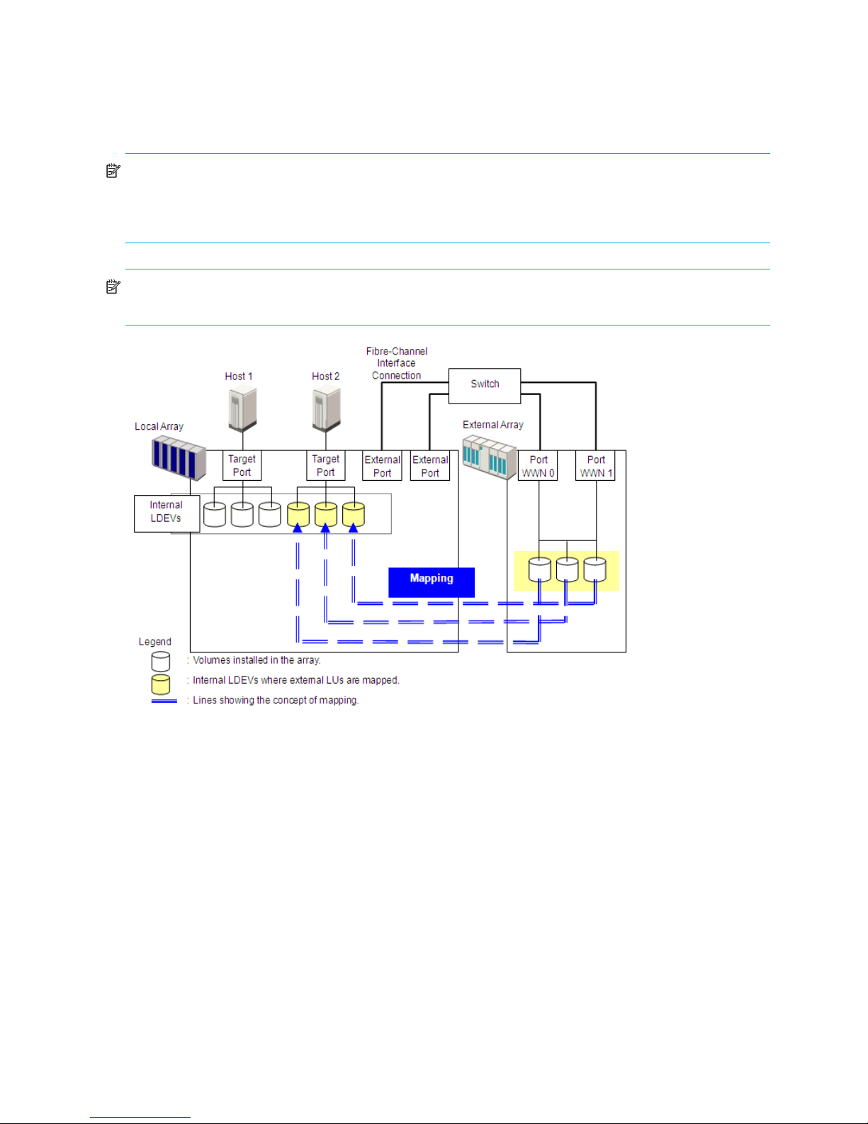
Figure 1 illustrates a local array and an external array that are connected using External Storage XP and
Fibre Channel hardware. In Figure 1, the external array is connected to the external port of the local
array via a switch (or hub) using a Fibre Channel interface. External is a local array port attribute used for
External Storage XP. In Figure 1, external LUs are mapped as local array VDEVs and LDEVs and,
consequently, as an LU.
NOTE: Do not access any external storage volume that is mapped as an External Storage XP volume
from a host connected directly to the external array. Also, do not access an External Storage XP mapped
external array volume using the external array’s functions (for example, local replication). After mapping
an external LU as a local array volume, access the mapped external LU only from the local array.
NOTE: Except on the MSA, a host can directly access external array volumes that have not been
mapped as local array volumes.
Figure 1 External Storage XP concept
14 Overview of connecting external arrays
Page 15

2 Preparing for External Storage XP operations
This chapter describes requirements, preparations, and notes for External Storage XP. This chapter also
describes the HP StorageWorks products you can use with External Storage XP.
System requirements
External Storage XP operations involve the local array, a storage array used as an external array, and the
licensed External Storage XP feature enabled on Command View XP or XP Remote Web Console. System
requirements for External Storage XP are:
• Local array (first array)
Install and enable all hardware and microcode required for External Storage XP operations in the
local array.
CAUTION: Before installing and enabling the hardware and microcode, see ”Managing cache
with external storage” on page 43 for instructions.
NOTE: Currently only an XP12000/XP10000/SVS200 can be used as a local array.
• External array (second array)
You also need a second storage device, called an external array in this user guide. For more
information, see ”Storage arrays that can be connected as external arrays” on page 15.
• HP StorageWorks Command View XP (running on a user-supplied Windows®-based PC) or XP Remote
Web Console
For instructions on installing and using Command View XP or XP Remote Web Console, see the
HP StorageWorks Command View XP user guide for XP Disk Arrays or the HP StorageWorks XP Remote
Web Console user guide for XP12000/XP10000/SVS200.
NOTE: You must run Command View XP or XP Remote Web Console in Modify mode to perform
External Storage XP operations. In View mode, you can only view External Storage XP information.
• External Storage XP
Enable the licensed External Storage XP feature in Command View XP or XP Remote Web Console.
Storage arrays that can be connected as external arrays
Table 2 lists storage arrays that can be connected as external arrays. Notes about the appearance of each
storage array in this document and in External Storage XP panes are also listed.
Table 2 Storage arrays that can be connected as external arrays
Storage array Notes
HP StorageWorks XP12000 Disk Array • In External Storage XP panes, the array appears as
“12000”.
• Alternate paths are in Multi mode (meaning that
dynamic load balancing across multiple active paths
is enabled).
HP StorageWorks XP10000 Disk Array • In External Storage XP panes, the array appears as
“10000”.
• Alternate paths are in Multi mode.
External Storage XP user guide 15
Page 16

Table 2 Storage arrays that can be connected as external arrays (continued)
Storage array Notes
HP StorageWorks XP1024/XP128 Disk Array • In External Storage XP panes, the arrays appear as
“1024” and “128”, respectively.
• Alternate paths are in Multi mode.
HP StorageWorks XP512/XP48 Disk Array • In External Storage XP panes, the arrays appear as
“512” and “48”, respectively.
• Alternate paths are in Multi mode.
HP StorageWorks XP256 Disk Array • In External Storage XP panes, the array appears as
“256”.
• Alternate paths are in Multi mode.
HP StorageWorks 200 Storage Virtualization System • In External Storage XP panes, the array appears as
“SVS200”.
• Alternate paths are in Multi mode.
HP StorageWorks 3000/5000 Enterprise Virtual Array
(Active/Standby and Active/Active controllers) or
HP StorageWorks 4000/6000/8000 Enterprise Virtual
Array (Active/Active controllers)
HP StorageWorks MSA1000/1500 (Active-Standby) • In this user guide, the arrays appear as “MSA
TagmaStore™ Universal Storage Platform subsystem • In this user guide, the array appears as
TagmaStore™ Network Storage Controller subsystem • In this user guide, the array appears as
TagmaStore™ Adaptable Modular Storage subsystem • In this user guide, the array appears as
• In this user guide, the arrays appear as “EVA
array”.
• In External Storage XP panes, the arrays appear as
“EVA”.
• Alternate paths are in Single mode (meaning that
dynamic load balancing across multiple active paths
is not enabled).
array”.
• In External Storage XP panes, the arrays appear as
“MSA”.
• Alternate paths are in Single mode.
“TagmaStore™ USP subsystem”.
• In External Storage XP panes, the array appears as
“USP”.
• Alternate paths are in Multi mode.
“TagmaStore™ NSC subsystem”.
• In External Storage XP panes, the array appears as
“NSC”.
• Alternate paths are in Multi mode.
“TagmaStore™ AMS subsystem”.
• In External Storage XP panes, the array appears as
“AMS”.
• Alternate paths are in Single mode.
TagmaStore™ Workgroup Modular Storage subsystem • In this user guide, the array appears as
16 Preparing for External Storage XP operations
“TagmaStore™ WMS subsystem”.
• In External Storage XP panes, the array appears as
“NSC”.
• Alternate paths are in Single mode.
Page 17

Table 2 Storage arrays that can be connected as external arrays (continued)
Storage array Notes
Lightning 9900V series subsystem • “Lightning 99xxV series subsystem” indicates the
Lightning 9970V and Lightning 9980V.
• In this user guide, the arrays appear as “Lightning
9900V subsystem”.
• In External Storage XP panes, the arrays appear as
“9970V” and “9980V”, respectively.
• Alternate paths are in Multi mode.
Thunder 9500V series subsystem • “Thunder 95xxV series subsystem” indicates the
Thunder 9530V, Thunder 9570V, and Thunder
9580V.
• In this user guide, the arrays appear as “Thunder
9500V subsystem”.
• In External Storage XP panes, the arrays appear as
“9500V”.
• Alternate paths are in Single mode.
Lightning 9900C series subsystem • “Lightning 99xxC series subsystem” indicates the
Lightning 9910 and Lightning 9960.
• In this user guide, the arrays appear as “Lightning
9900 subsystem”.
• In External Storage XP panes, the Lightning 9910
appears as “0401”, and the Lightning 9960
appears as “0400”.
• Alternate paths are in Multi mode.
A/H-6593 subsystem • In External Storage XP panes, the array appears as
“300”.
• Alternate paths are in Multi mode.
SANRISE Universal Storage Platform subsystem • In this user guide, the array appears as “SANRISE
USP subsystem”.
• In External Storage XP panes, the array appears as
“USP”.
• Alternate paths are in Multi mode.
SANRISE Network Storage Controller subsystem • In this user guide, the array appears as “SANRISE
NSC subsystem”.
• In External Storage XP panes, the array appears as
“NSC”.
• Alternate paths are in Multi mode.
SANRISE Adaptable Modular Storage subsystem • In this user guide, the array appears as “SANRISE
AMS subsystem”.
• In External Storage XP panes, the array appears as
“AMS”.
• Alternate paths are in Single mode.
SANRISE Workgroup Modular Storage • In this user guide, the array appears as “SANRISE
WMS subsystem”.
• In External Storage XP panes, the array appears as
“WMS”.
• Alternate paths are in Single mode.
External Storage XP user guide 17
Page 18

Table 2 Storage arrays that can be connected as external arrays (continued)
Storage array Notes
SANRISE9900V series subsystem • “SANRISE99xxV series subsystem” indicates the
SANRISE9970V and SANRISE9980V.
• In this user guide, the arrays appear as
“SANRISE9900V subsystem”.
• In External Storage XP panes, the arrays appear as
“9970V” and “9980V”, respectively.
• Alternate paths are in Multi mode.
SANRISE9500V series subsystem • “SANRISE95xxV series subsystem” indicates the
SANRISE9530V, SANRISE9570V, and
SANRISE9580V.
• In this user guide, the arrays appear as
“SANRISE9500V subsystem”.
• In External Storage XP panes, the arrays appear as
“9500V”.
• Alternate paths are in Single mode.
SANRISE2000 series subsystem • “SANRISE2000 series subsystem” indicates the
SANRISE2200 and SANRISE2800.
• In this user guide, the arrays appear as
“SANRISE2000 subsystem”.
• In External Storage XP panes, the SANRISE2200
appears as “0401”, and the SANRISE2800
appears as “0400”.
• Alternate paths are in Multi mode.
SANRISE H12000 subsystem • In External Storage XP panes, the array appears as
“12000”.
• Alternate paths are in Multi mode.
SANRISE H10000 subsystem • In External Storage XP panes, the array appears as
“10000”.
• Alternate paths are in Multi mode.
SANRISE H1024/H128 subsystem • In External Storage XP panes, the arrays appear as
“1024” and “128”, respectively.
• Alternate paths are in Multi mode.
SANRISE H512/H48 subsystem • In External Storage XP panes, the arrays appear as
“512” and “48”, respectively.
• Alternate paths are in Multi mode.
SANRISE H256 subsystem • In External Storage XP panes, the array appears as
“256”.
• Alternate paths are in Multi mode.
IBM Storage Subsystem For specific supported storage arrays, contact your
HP account support representative.
EMC Storage Subsystem For specific supported storage arrays, contact your
HP account support representative.
Fujitsu Storage Subsystem For specific supported storage arrays, contact your
HP account support representative.
NEC Storage Subsystem For specific supported storage arrays, contact your
18 Preparing for External Storage XP operations
HP account support representative.
Page 19
CAUTION: For more information about alternate path modes, see ”Setting alternate paths for external
LUs” on page 84.
Contact your HP account support representative for the latest external array and FC switch support matrix.
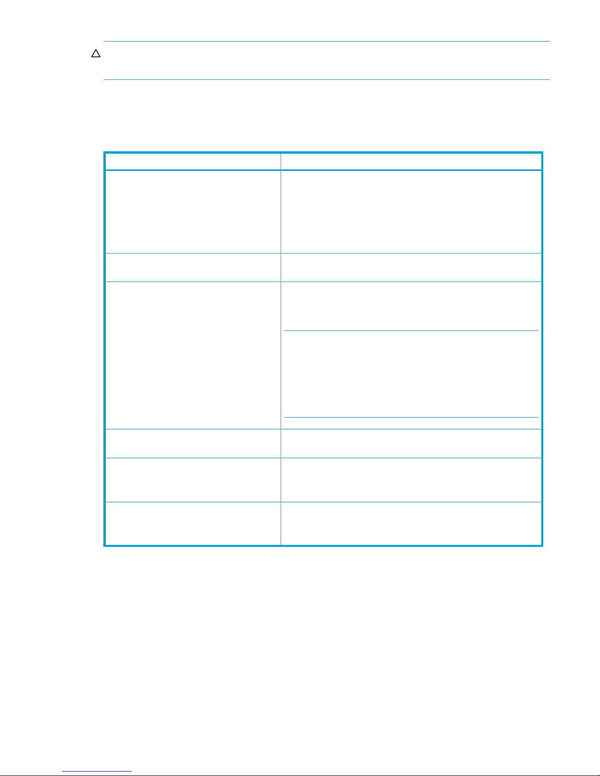
External Storage XP requirements
Table 3 External Storage XP requirements
Item Requirement
Required products
Maximum number of external LUs
addressable per local array port
Maximum number of external LUs that can
be connected
Maximum number of FC paths that can exist
to one external LU
• HPStorageWorks Command View XP version 2.0 or later, or
XP Remote Web Console
• HP StorageWorks LUN Configuration and Security Manager
XP (for
setup)
• HP StorageWorks RAID Manager XP version 01.12.06 or later
(if Business Copy XP is used)
1,024 per port
• For the XP12000, 15,360 volumes can be connected
• For the XP10000/SVS200, 8,192 volumes can be connected
• 1,024 volumes can be connected per port
NOTE: If you use Snapshot XP, the number of external LUs that can
be connected is as follows:
• For the XP12000:
Number of external LUs + Number of virtual LUs ≤15,360
• For the XP10000/SVS200:
Number of external LUs + Number of virtual LUs ≤8,192
8
Maximum capacity of an external LU 2 TB (4,294,967,296 blocks) per external LU (OPEN-V)
If you specify an external LU that is larger than 2 TB, you can only
access data stored in the field up to 2 TB.
Minimum capacity of an external LU About 38 MB (77,760 blocks) per external LU (non-OPEN-V)
When the volume’s emulation type is OPEN-V, minimum capacity
is about 47 MB (96,000 blocks) per external LU.
Installing External Storage XP
To perform External Storage XP operations with Command View XP or XP Remote Web Console, you must
install an External Storage XP license key.
1. Start Command View XP or XP Remote Web Console for the local array.
2. Enable the External Storage XP options in Command View XP or XP Remote Web Console and on
each External Storage XP array.
For instructions, see the HP StorageWorks Command View XP user guide for XP Disk Arrays or the
HP StorageWorks XP Remote Web Console user guide for XP12000/XP10000/SVS200.
Preparing for External Storage XP settings
Before using External Storage XP, collect the information necessary for defining its settings. The following
information is required:
External Storage XP user guide 19
Page 20

• Ports that can be set to external ports (see ”External ports” on page 20)
• External array and LUs to map to the internal LDEVs (see”External LU to be mapped” on page 20)
• Configuration of external LU groups (see ”External LU groups” on page 20)
• Configuration of external LU attributes (see ”External LU attributes set by mapping” on page 20)
• Configuration of alternate paths (see ”Alternate paths” on page 22)
External ports
Local array ports used for External Storage XP must be set to a designation of External. When the external
array is connected to the local array’s external port via Fibre Channel, you can view information about
the external array from Command View XP or XP Remote Web Console. The external array can be
connected only to ports designated as External.
To set the port attribute to External, you must release any existing paths currently configured for the port.
You cannot change the attribute of the port where paths are set to External. Before starting External
Storage XP operations, you must know which ports you can change to External.
NOTE: You cannot use ports with attributes set for remote copy software (such as RCU Target or Initiator)
or other features as external ports for External Storage XP. If the port attribute is set to something other
than External, change its attribute to External. Flex Copy XP and External Storage XP can share an
XP12000/XP10000/SVS200 port with an attribute of External.
For instructions, see ”Setting a local array’s port attributes” on page 70.
External LU to be mapped
When connecting an external array to an external port, you can map LUs in the external array (external
LUs) as LDEVs in the local array (internal LDEVs). Verify which LUs in which external array can be mapped
as internal LDEVs.
You can map only one external LU to a given internal LDEV and map up to a theoretical limit of 1,024
external LUs per local array port.
An external LU’s maximum available capacity depends on the emulation type set when the LU is mapped.
You cannot access data stored in the field over the external LU’s maximum available capacity. To set an
emulation type other than OPEN-V, you cannot map external LUs smaller than 38 MB (77,760 blocks). To
set the OPEN-V emulation type, you cannot map external LUs of smaller than 47 MB (96,000 blocks). For
more information about the capacity of the external LU for each emulation type, see ”Required volume
capacity for emulation types” on page 127.
External LU groups
When mapping an external LU as an internal LDEV, you must register the external LU in an external LU
group.
You can classify external LUs set by External Storage XP into groups according to their use. The group is
called an external LU group (ExG). For instance, you can register several LUs in one external array to one
external LU group. Or, if data you want to manage in a chunk is stored in LUs in various external arrays,
you can register those LUs in one external LU group, and manage them as a block.
You must assign a number from 1 to 16,384 to each external LU group. For the XP12000, you can create
a maximum of 15,360 external LU groups. For the XP10000/SVS200, you can create a maximum of
8,192 external LU groups. You can register a maximum of 256 volumes in one external group.
External LU attributes set by mapping
When mapping an external LU as an internal LDEV, use the Add LU pane in External Storage XP to set the
external LU’s attributes. For instructions, see ”Mapping external LUs (Add LU)” on page 70.
The following are the external LU’s attributes:
• Emulation type
20 Preparing for External Storage XP operations
Page 21

Set the mapped LU’s emulation type by selecting any emulation type from the drop-down list.
However, if you plan to use the mapped LU for Flex Copy XP operations, or you plan to access
existing data in the external LU, you must select the OPEN-V emulation type to avoid data resizing.
If you plan to use existing data in the external LU from the local array after mapping, you must select
the OPEN-V emulation type. For example, to migrate existing data in the external LU to the local array
volume, you must set the OPEN-V emulation type when mapping the external LU.
You must also select the OPEN-V emulation type when VMA of LUN Security XP Extension is set for the
external LU on the external array side.
If you select an emulation type other than OPEN-V, additional space is taken for XP management
information. This means that after mapping, LU capacity is less than the actual external LU capacity
(and the original data must be considered lost). For more information about volume capacity, see
”Limitations on External Storage XP operations” on page 32.
• IO Suppression mode (Enable or Disable)
When mapping an LU, determine whether to suppress I/O operations from hosts (via the local array)
to the mapped external LU.
If you select Enable, you can use the mapped LU only for Flex Copy XP operations.
If you select Disable, a host connected to the local array can use the mapped external LU as if it were
an LU inside the local array, but you cannot use the LU for Flex Copy XP operations.
You can sel ect Enable only when you set the OPEN-V emulation type for the mapped LU. When you
set an emulation type other than OPEN-V, the IO Suppression mode is automatically set to Disable.
• Cache Mode (Enable or Disable)
Cache mode specifies if I/O from the host is propagated synchronously or asynchronously to the
external storage device. All I/O to and from the local array in both cache modes always uses some
amount of cache. Write operations are always backed up in duplex cache.
If you select Enable, the local array signals the host that an I/O operation completed after receiving
the data into the local array’s cache memory, and then asynchronously destages the data to the
external array’s cache where it is asynchronously destaged to disk.
If you select Disable, the local array signals the host that an I/O operation completed only after the
local array has synchronously written the data to the external array’s cache. The external array’s
cache then asynchronously destages this data to disk.
NOTE: Users should disable cache for low price/performance arrays, such as the HP MSA
arrays. The MSA array ports are slower than the XP FC ports. Disabling cache prevents
applications that use the MSA from consuming significant amounts of XP cache.
NOTE: As an option, consider using XP Disk/Cache Partition as a recommended best practice for
managing XP cache consumption. See ”Managing cache with external storage” on page 43 or
contact your HP account support representative for more information about optimizing cache
usage for external storage.
When IO Suppression mode is set to Enable, Cache Mode changes by default to Disable.
If you use an external LU and set Cache Mode to Disable for Cache LUN XP operations, you cannot
use the Cache LUN XP Bind mode. For more information, see the HP StorageWorks Cache LUN XP
user guide for XP12000/XP10000/SVS200.
NOTE: If you set the emulation type of the mainframe system for the mapped LU, host I/O is
always propagated asynchronously to the external LU regardless of the Cache Mode setting.
• CLPR
When using XP Disk/Cache Partition to partition cache memory, set the cache logical partition (CLPR)
used for accessing the mapped LU. You can also specify whether the CU selected at mapping is
External Storage XP user guide 21
Page 22

restricted to the storage management logical partition (SLPR) the CLPR belongs to. For more
information about CLPRs and SLPRs, see the HP StorageWorks XP Disk/Cache Partition user guide.
Alternate paths
When mapping an external LU as an internal LDEV, paths are set from the internal LDEV to the external
LU.
If two or more paths to the external LU are equipped from different clusters, the number of paths you set
when mapping the volume are available. If one path is equipped, only that path is available.
You can set up to eight paths to each external LU, including paths automatically set. Among the paths to
the external LU, the path with the highest priority is called the primary path, and other paths are alternate
paths.
Alternate path modes include Single mode and Multi mode. The alternate path mode, Single mode or
Multi mode, depends on the connected external array. For Single mode, only the path with the highest
priority (primary path) is used to execute I/Os to the external LU. When an error occurs in the primary
path, the path with the second highest priority is used (that is, no per-LU dynamic load balancing across
paths). For Multi mode, all set paths are used at the same time. The paths are used to execute I/Os to the
external LU, distributing the work load (round-robin processing).
For example, when an external LU volume with an alternate path in Single mode is mapped to an internal
LDEV using External Storage XP, host I/O operations to the external LU via the local array are normally
enabled using the mapped path. If the mapped path is not available (for instance, during array
maintenance or following a failure in the channel processor), the path is switched automatically to the
alternate path (if available). As long as an alternate path is available, host I/O operations continue as
usual, even when an error occurs in the original path.
NOTE: When the primary path cannot be used for the length of the Path Blockade Watch timer (for
example, 180 seconds), the path is switched to an alternate path.
If you have not configured any alternate paths, host I/O operations are suspended when the primary path
becomes unavailable (such as during array maintenance operations or following a failure in the channel
processor).
HP recommends configuring alternate paths for safer operation and increased bandwidth. For
instructions, see ”Setting alternate paths for external LUs” on page 84.
You can set alternate paths when the external LUs are mapped as the internal LDEVs (see ”Mapping
external LUs (Add LU)” on page 70). You can also set alternate paths after completing the mapping
operation (see ”Setting alternate paths for external LUs” on page 84).
Example of an alternate path configuration
Figure 2 shows an example of an alternate path configuration. In Figure 2, external array ports WWN A
and WWN B are connected to CL1-A and CL2-A, respectively, which are designated as external ports in
22 Preparing for External Storage XP operations
Page 23
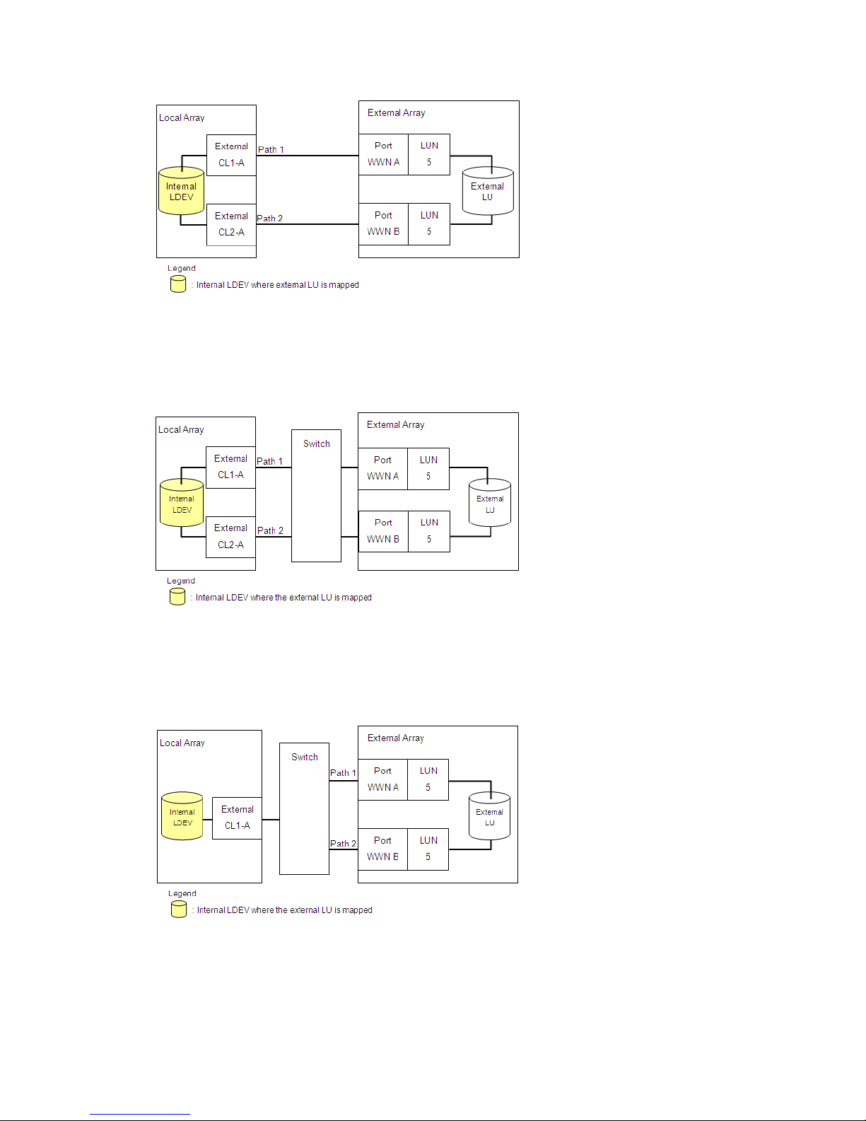
the local array. You must specify the port of a different cluster in the local array for the alternate path, as
ports CL1 and CL2 are specified in the figure.
Figure 2 Example of alternate path configuration
Figure 3 shows another example of an alternate path configuration. In Figure 3, two ports are specified in
the local array and connected to ports in the external array via switches. In this example, two ports from
different XP12000/XP10000/SVS200 clusters are specified in the local array, thereby making it possible
to configure an alternate path for high availability.
Figure 3 Example of alternate path configuration using two switches
In Figure 4, two paths are configured between the internal LDEV and external LU. However, only one port
is specified in the local array and two ports are specified in the external arrays via the switch. Since two
ports of different clusters must be set in the local array for External Storage XP to use alternate path
settings, HP does not recommend the configuration shown in Figure 4.
Figure 4 Example of incorrect alternate path configurations
Examples of switching I/O execution paths to alternate paths
There are two alternate path modes: Single mode and Multi mode. This section describes examples of the
performance when the I/O execution path switches to the alternate path for each path mode.
External Storage XP user guide 23
Page 24
For more information about path status, see ”Adding alternate paths by selecting multiple external LUs
(Add Paths)” on page 89.
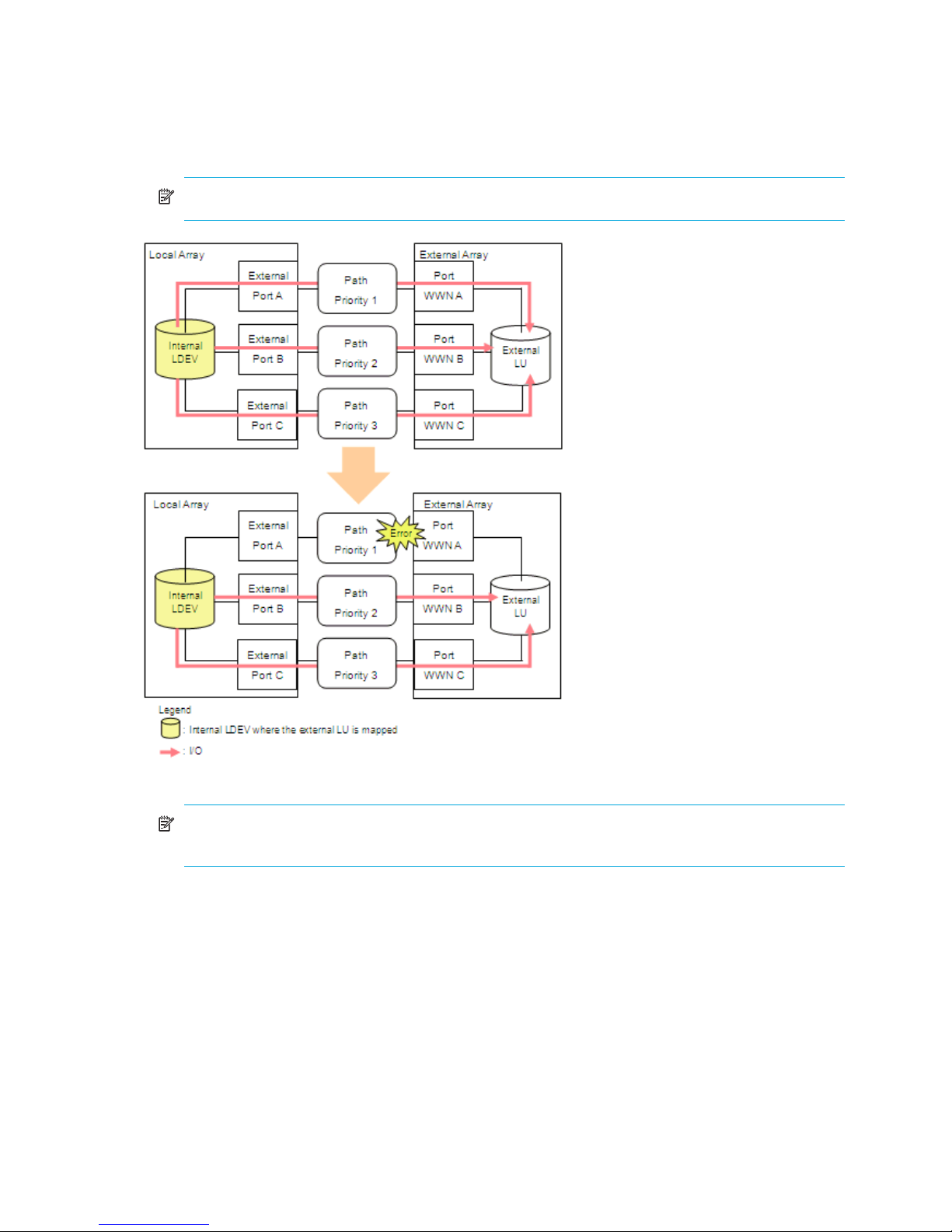
• Alternate path mode is Multi mode
Figure 5 shows an example of when the alternate path mode is Multi mode. When an error occurs in
one path, I/Os execute using paths other than the error path.
NOTE: As you restore the error path, use of the restored path automatically resumes.
Figure 5 Alternate path mode is Multi mode
NOTE: In Multi mode, active I/O load balancing occurs across external array ports and
controllers. The XP and EMC DMX are examples of external arrays that use Multi mode.
• Alternate path mode is Single mode
Figure 6 shows an example of when the alternate path mode is Single mode. When an error occurs in
the path used for I/Os, the I/O execution path switches to the path with the second highest priority.
24 Preparing for External Storage XP operations
Page 25
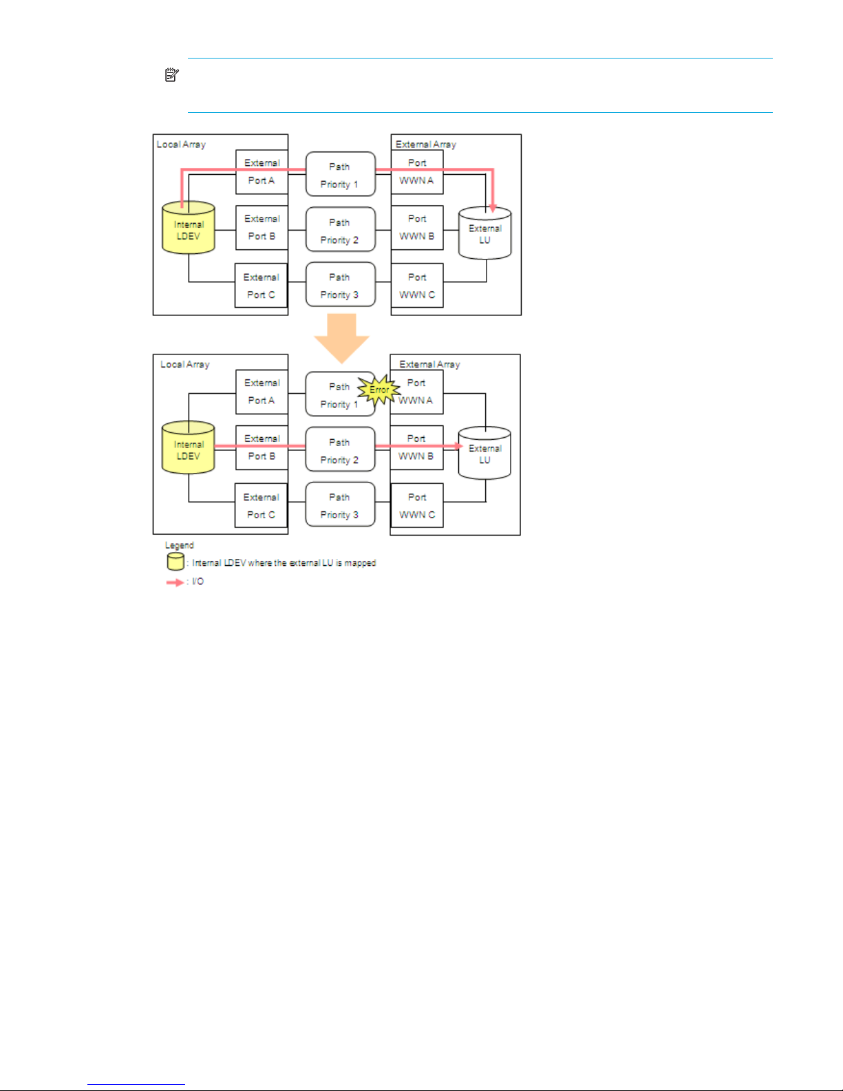
NOTE: As you restore the path with a priority higher than the current path, the I/O execution path
automatically switches to the restored path with the highest priority.
Figure 6 Alternate path mode is Single mode
• Alternate path mode is Single mode and at least one alternate path is in Standby status
Figure 7 shows an example of when the alternate path mode is Single mode and there are alternate
paths in Normal and Standby status. Figure 8 shows another example of when the alternate path mode
is Single mode. In Figure 8, there are alternate paths in Standby status only.
When an error occurs in the path used for I/Os, the I/O execution path switches to the path with the
second highest priority in Normal status (Figure 7). If there is no path in Normal status other than the
path used for I/Os, the status of the path in Standby status automatically changes to Normal and the
I/O execution path switches to that path (Figure 8).
External Storage XP user guide 25
Page 26
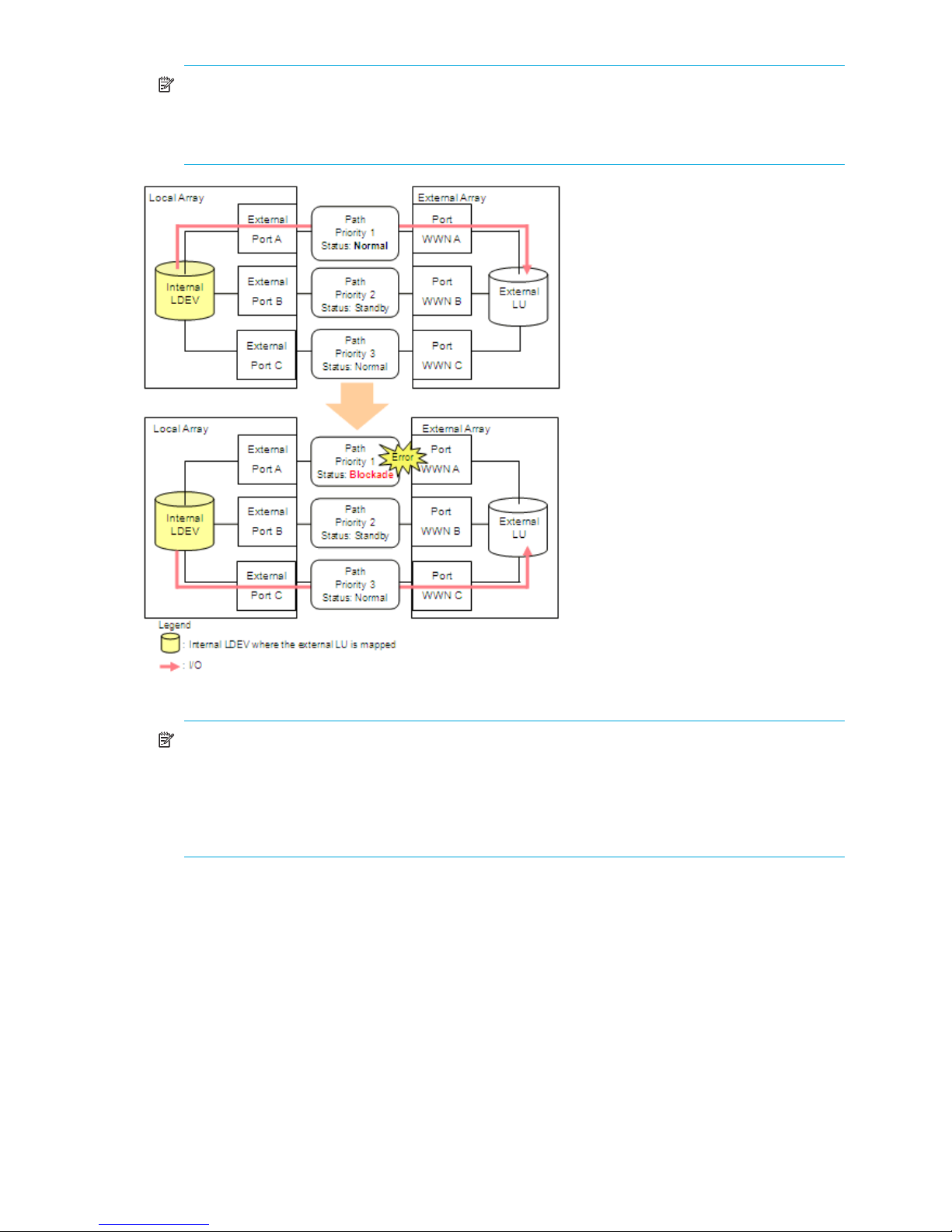
NOTE: When the external array is an EVA array, as you restore the path with the highest priority,
the I/O execution path switches back to the restored highest priority path. In this case, the status of
the path for which the status changed to Normal when the error occurred changes back to
Standby.
Figure 7 Alternate path mode is Single mode with alternate paths in Normal and Standby
NOTE: External arrays with Asymmetrical Active/Active (AAA) controllers, such as the Hitachi
Thunder, are an example of Figure 7. A notable characteristic of using AAA controller arrays as
external storage is that paths to alternate ports on the owning controller for a given external LU are
seen as Normal status, but I/O load balancing does not occur (either across controllers or across
ports to the owning controller). Paths to the non-owning external controller’s ports are shown as
Standby status.
26 Preparing for External Storage XP operations
Page 27
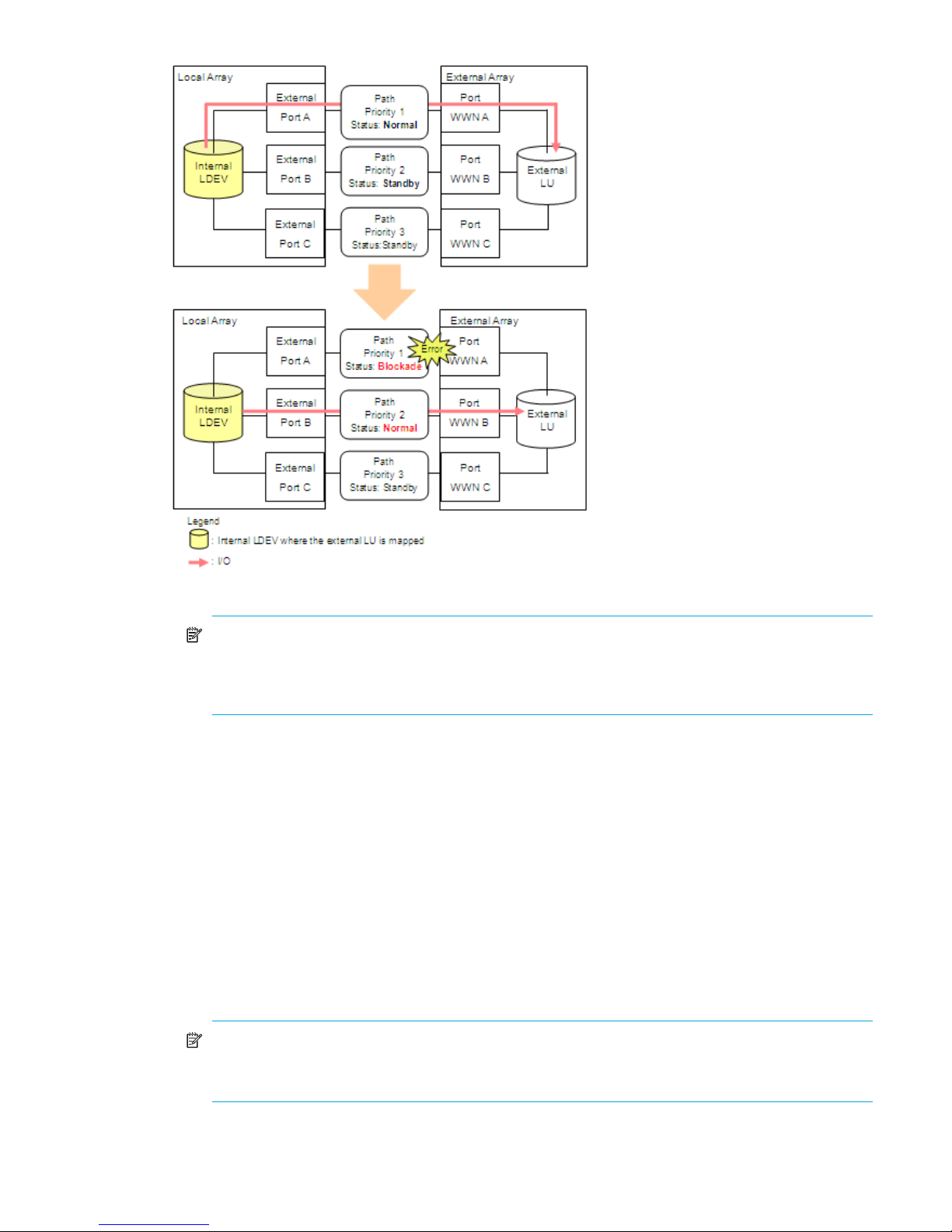
Figure 8 Alternate path mode is Single mode with alternate paths in Standby only
NOTE: External arrays with Active/Standby (A/S) controllers, such as the MSA, are an example of
Figure 8. A notable characteristic of using A/S controller arrays as external storage is that there is
typically only a single port to the owning controller. Paths to the non-owning external controller’s
ports are shown as Standby status. I/O load balancing does not occur across external controllers.
Powering arrays on or off
This section describes procedures for powering local and external arrays on or off after External Storage
XP operations have started.
These procedures use the following commands:
• Disconnect Subsystem
Execute the Disconnect Subsystem command from the Command View XP or XP Remote Web Console
GUI when you need to perform maintenance or stop the local or external array. This command stops
acceptance of all host I/O operations to the external LU mapped as the internal LDEV. All outstanding
data in cache memory on the local array intended for the external LU is written (de-staged) to the
external LU.
For instructions on executing the Disconnect Subsystem command, see ”Disconnecting external arrays
or LUs” on page 95.
NOTE: To disconnect an individual LU, use the Disconnect Volume command. To delete a single
external LU’s mapping, use the Disconnect Volume command and then the Delete LU command. For
instructions, see ”Deleting external LU mappings (Delete LU)” on page 101.
• Check Paths & Restore Vol.
External Storage XP user guide 27
Page 28

This command checks if defined information about the mapped external LU and the actual external LU
status match. If the external LU can be used as the mapped local array volume, the external LU is set to
accept I/O, and you can continue using the external LU as a mapped LU.
Use this command to restore the external LU, which is set to reject host I/O operations by the
Disconnect Subsystem or Disconnect Volume command, as the mapped volume. You can execute the
Check Paths & Restore Vol. command for the entire array or an individual LU.
If an error occurs in the external storage path such that the command fails, correct the error so the path
can be restored, and execute the Check Paths & Restore Vol. command again.
For instructions, see ”Checking the connection status and resuming external LU operations (Check Paths
& Restore Vol.)” on page 97.
NOTE: When executing the Check Paths & Restore Vol. command, if the external LU is ready to
be restored as the mapped LU, the external LU is set to Available. However, if the external LU is not
ready to be restored, the external LU status remains as Blocked.
The following sections describe procedures to power the local and external arrays on or off.
CAUTION: To power both the local and external arrays off, first power off the local array, and then
power off the external array.
CAUTION: To power both the local and external arrays on, first power on the external array, and then
power on the local array. If both are supplied by a common failed power source, one option to ensure
that the external array is online and available before the XP powers up is to place the external array on
an Uninterruptible Power Supply (UPS).
Powering local arrays on or off
To power local arrays off
1. Stop read and write I/Os to the external LU that is mapped as a local array internal LDEV.
2. Perform other operations required before powering the local array off.
3. Turn the local array’s power off.
NOTE: As you turn the local array’s power off, all data for the external LU in the local array’s cache
memory is written in the external LU (all data is destaged).
To power local arrays on
1. Power on the external array containing the external LU mapped as a local array internal LDEV.
2. Turn on the local array’s power.
CAUTION: When the local array is powered off after executing the Disconnect Subsystem command,
you cannot access the mapped external LU from the local array when you first power on the local array.
You must execute the Check Paths & Restore Vol. command to resume using the mapped external LU. The
Check Paths & Restore Vol. command checks if the defined information and actual status of the external LU
mapped as a local array volume match. If the external LU is ready to be used as a mapped volume, the
LU is set to accept I/Os and you can resume using the volume as a mapped volume.
28 Preparing for External Storage XP operations
Page 29
CAUTION: When the Disconnect Subsystem or Disconnect Volume command is executed and all data in
cache memory is written to the external LU, the displayed information for Ex-Dev. Status in the Device list
becomes Disconnect.
Powering external arrays on or off
To power external arrays off
1. Stop read and write I/Os to the external LU that is mapped as a local array internal LDEV and is
located in the external array you want to power off.
2. Execute the Disconnect Subsystem command for the external array you want to power off.
Additional I/O to the external LU is stopped and all data in the local array cache memory is written to
the external LU (all data is destaged). For instructions, see ”Disconnecting external arrays or LUs” on
page 95.
3. Perform other operations required before powering the external array off.
4. Power the external array off.
CAUTION: After executing the Disconnect Subsystem command, if you need to use the mapped external
LU again, execute the Check Paths & Restore Vol. command.
To power external arrays on
1. Power on the external array containing the external LU that is mapped as a local array internal LDEV.
2. Execute the Check Paths & Restore Vol. command. For instructions, see ”Checking the connection status
and resuming external LU operations (Check Paths & Restore Vol.)” on page 97.
CAUTION: When powering the external array off after executing the Disconnect Subsystem command,
you cannot access the mapped external LU from the local array when you initially turn on the external
array. You must execute the Check Paths & Restore Vol. command to resume using the mapped external
LU. The Check Paths & Restore Vol. command checks the defined information and the actual status of the
external LU mapped as a local array internal LDEV. If the external LU is ready to be used as a mapped
volume, the LU is set to accept I/Os and you can resume using the LU as a mapped volume.
Using mapped external LUs from the host connected to the local array
The following sections describe examples of using the mapped external LU from the host connected the
local array.
Writing new data to mapped external LUs
Figure 9 shows an example of writing new data in the mapped external LU from the host connected to the
local array.
1. Use the External Storage XP GUI to map the LU in the external array as an internal LDEV of the local
array.
CAUTION: You must set IO Suppression mode to Disable.
You can select the mapped volume’s emulation type as required. If you select an emulation type for an
open-system (such as OPEN-V), go to step 2. If you select an emulation type for a mainframe system
(such as 3390-3), go to step 3.
For more information, see ”Mapping external LUs (Add LU)” on page 70.
2. For open-system emulation types (such as OPEN-V, which HP recommends), the status of the mapped
LDEV is set to Normal and is not automatically formatted. To optimally initialize the mapped LU’s data
External Storage XP user guide 29
Page 30
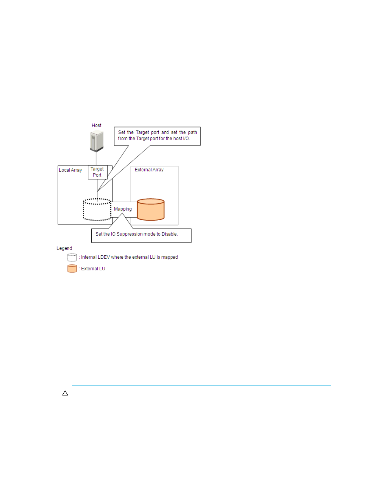
area, use Volume Manager to format the mapped LU. For instructions, see the HP StorageWorks LUN
Configuration and Security Manager XP user guide for the XP12000/XP10000/SVS200.
To to step 4.
3. For mainframe-system emulation types (for example, 3390-XX), the status of the mapped LU is set to
Blockade, pending resizing and formatting. Use Volume Manager to format the volume. If you
mapped a volume for which the data area is already zero-formatted on the external array side, use
Volume Manager’s Write to Control Blocks operation to restore the volume. For instructions, see the
HP StorageWorks LUN Configuration and Security Manager XP user guide for the
XP12000/XP10000/SVS200.
4. Configure the path from the Target port to the mapped volume to perform host I/O operations. The
mapped LDEV is available for host I/O operations.
After the path is set, host I/O operations to the mapped LU are available.
Figure 9 Writing new data to mapped external LUs
Using existing data in mapped external LUs
Figure 10 shows an example of using existing data in a mapped external LU from the host connected to
the local array.
1. From the host connected to the external array, write data to the LU in the external array.
2. Use External Storage XP to map the LU in the external array containing data as an internal LDEV of the
local array.
When mapping the external LU, set the following attributes for the mapped LU:
• Emulation type: OPEN-V
• IO Suppression mode: Disable
For more information, see ”Mapping external LUs (Add LU)” on page 70.
CAUTION: You must set the emulation type to OPEN-V to read existing data in the mapped
external LU from the local array side. Other emulation modes require that the data space be
resized, which in effect destroys existing data. Once an external LU is mapped to the local array
for use by External Storage XP, direct host access to that LU is no longer allowed. Also set the
emulation type to OPEN-V when the VMA of LUN Security XP Extension is set for the external LU on
the external array side.
3. Configure the path from the Target port to the mapped LU to perform host I/O operations.
30 Preparing for External Storage XP operations
Page 31

After the path is set, host I/O operations to the mapped volume are available.
NOTE: Do not access any external storage volume that is mapped as an External Storage XP volume
from a host connected directly to the external array. Also, do not access an External Storage XP mapped
external array volume using the external array’s functions (for example, local replication). After mapping
an external disk volume as a local array volume, access the mapped external disk volume only via the
local array.
NOTE: Except on the MSA, a host can directly access external array volumes that are not mapped as
local array volumes.
Figure 10 Using existing data in mapped external LUs (without formatting)
Uninstalling External Storage XP
To uninstall External Storage XP, cancel any existing Flex Copy copy pairs, and delete any external LU
mappings.
1. Log in to Command View XP or XP Remote Web Console. For instructions, see the HP StorageWorks
Command View XP user guide for XP Disk Arrays or the HP StorageWorks XP Remote Web Console
user guide for XP12000/XP10000/SVS200.
2. Click the External Storage XP button ( ). External Storage XP starts.
3. Cancel any existing Flex Copy pairs. For instructions, see the HP StorageWorks Flex Copy XP user
guide.
4. Delete any external LU mapping. For instructions, see ”Deleting external LU mappings (Delete LU)” on
page 101.
5. Use the Command View XP or XP Remote Web Console Licensing module to remove the Flex Copy XP
license key. For instructions, see the HP StorageWorks Command View XP user guide for XP Disk
Arrays or the HP StorageWorks XP Remote Web Console user guide for
XP12000/XP10000/SVS200.
6. For the local array, use the Command View XP or XP Remote Web Console Licensing module to
remove the External Storage XP license key. For instructions, see the HP StorageWorks Command
View XP user guide for XP Disk Arrays or the HP StorageWorks XP Remote Web Console user guide
for XP12000/XP10000/SVS200.
External Storage XP user guide 31
Page 32

Limitations on External Storage XP operations
• External LUs can be mapped as any CU:LDEV combination from 00:00 to 3F:FF.
• Only ports in SLPR0 can be set as external ports.
• Do not access any external storage volume that is mapped as an External Storage XP volume from a
host connected directly to the external array. Also, do not access an External Storage XP mapped
external array volume using the external array’s functions (for example, local replication). After
mapping an external disk volume as a local array volume, access the mapped external disk volume
only via the local array.
• Except on the MSA, a host can directly access external array volumes that have not been mapped as
local array volumes.
• Continuous Access XP P-VOLs, S-VOLs, and journal volumes are not supported on MSA arrays.
• HP does not recommend that volumes involved with Snapshot XP reside on external MSA arrays.
• If you map an external LU that is more than 2 TB with the setting of OPEN-V emulation type, you can
access data stored in the field up to 2 TB. You cannot access data stored in the field over 2 TB.
• When mapping a volume that has a capacity of 2 TB or less in the external array and (external LU)
with the OPEN-V emulation type, the LU is defined as an internal LDEV with the same capacity as the
mapped external LU. That is, no space is forfeited for management space, and no formatting of that
data occurs. Therefore, OPEN-V is recommended.
Figure 11 Example of external LU with 2 TB or less
• If you map an external LU that is equal to or greater than 575.98 GB with an OPEN emulation type
other than OPEN-V, you can access data stored in the field up to 575.98 GB. You cannot access data
stored in the field over 575.98 GB.
However, for emulation types with a small base capacity, some of the field of 575.98 GB might not
be available. For more information, see ”Required volume capacity for emulation types” on page 127.
• If you map an external LU that is equal to or greater than 575.98 GB with a 3380 mainframe
emulation type, you can access data stored in the field up to 575.98 GB. You cannot access data
stored in the field over 575.98 GB.
However, for emulation types with a small base capacity, some of the field of 575.98 GB might not
be available. For more information, see ”Required volume capacity for emulation types” on page 127.
• If you map an external LU that is equal to or greater than 695.98 GB with a 3390 mainframe
emulation type, you can access data stored in the field up to 695.98 GB. You cannot access data
stored in the field over 695.98 GB.
However, for emulation types with a small base capacity, some of the field of 695.98 GB might not
be available. For more information, see ”Required volume capacity for emulation types” on page 127.
• If you plan to use the mapped external LU from the mainframe OS (volume is mapped with a 3380-x
or 3390-x mainframe emulation type), you must select an external LU that consists of one LDEV or you
must first adjust the capacity of the external LU to be mapped. If multiple LDEVs exist in one external LU
and if numerous I/Os are made to these LDEVs, the read and write commands might timeout. When
the commands timeout, the SIM (21D2xx) is reported.
• When mapping an external LU as internal LDEVs with emulation types other than OPEN-V, the number
of volumes and the volume capacity of the mapped internal LDEVs depends on the original external
LU’s capacity and each emulation type’s normal size. When mapping an external LU using emulation
types other than OPEN-V, an XP array management information area is required in the mapped LU.
This means that the capacity available after mapping is slightly smaller than the actual external LU
32 Preparing for External Storage XP operations
Page 33

capacity. Available capacity decreases by the size of the XP array management information area,
and all prior data must be considered lost. For more information, see the HP StorageWorks Flex Copy
XP user guide.
Figure 12 shows an example where the external LU’s original capacity is larger than (or a multiple of)
the normal size of the local array’s emulation type (OPEN-3 in this example). Therefore, in this
example, the local array can realize two fully-sized OPEN-3 LDEVs, with some space (insufficient to
create a full OPEN-3) left over.
Figure 12 External LU capacity is larger than the specified emulation type’s basic capacity (OPEN-3
example)
Figure 13 shows an example where the external LU’s original capacity is smaller than the normal size
of the local array’s emulation type. In this example, since the resulting space is insufficient to create a
local array OPEN-3 LDEV, you can designate it as either a local array OPEN-V or an OPEN-3 CVS
LDEV. If the external LU were an XP of OPEN-3 emulation type, forfeiting a small amount of
management space would also result in an OPEN-3 CVS volume or an OPEN-V.
Figure 13 External LU capacity is smaller than the specified emulation type’s basic capacity
• IO Suppression mode can only be selected when the volume being mapped is set to the OPEN-V
emulation type. If a different emulation type is set, IO Suppression mode is automatically set to Disable.
• If you use the mapped external LU from the host connected to the local array, set the IO Suppression
mode to Disable when mapping the LU. For External Storage XP, select Disable. For Flex Copy XP, select
Enable.
• If you use the mapped external LU for the copy source or copy destination volume for a Flex Copy XP
pair, set the emulation type to OPEN-V when mapping the volume.
• If you use the mapped external LU for the copy source or copy destination volume for a Flex Copy XP
pair, set IO Suppression mode to Enable when mapping the volume.
• The local array does not force the external array to reserve the mapped external LU. Therefore, do not
write directly to an external array LU (that is, without writing via the local XP array) with IO Suppression
mode set to Disable from the external array side.
External Storage XP user guide 33
Page 34

If Flex Copy XP operations are in progress for a volume with IO Suppression mode set to Enable, be
careful when updating data in that external LU from the external array side.
• IO Suppression mode is automatically set to the same status for all LDEVs in a given external LU.
• Cache Mode is automatically set to the same status for all LDEVs in a given external LU.
• If you set an open-system emulation type (such as OPEN-V) when mapping the external LU, you can
use the external LU immediately.
To optionally initialize the LU’s data area, use Volume Manager to format the LU. For instructions, see
the HP StorageWorks LUN Configuration and Security Manager XP user guide for the
XP12000/XP10000/SVS200.
• If you set a mainframe-system emulation type (such as 3390-3) when mapping the external LU, format
the LU or perform the Write to Control Blocks operation to make the volume usable.
After the mapping operation, the mapped LU’s status is Blockade. Use Volume Manager to format the
volume or perform the Write to Control Blocks operation to make the volume usable.
• If you mapped a volume that has already been zero-formatted on the external array side, perform
the Write to Control Blocks operation.
• If you mapped a volume that has not been zero-formatted on the external array side, format the
volume on the local array side.
For instructions on the formatting and Write to Control Blocks operations, see the HP StorageWorks
LUN Configuration and Security Manager XP user guide for the XP12000/XP10000/SVS200.
If you format the external array’s mapped LU from the external array side, data that existed prior to
formatting cannot be ensured. When using the mapped external LU from the mainframe OS, format the
mapped volume from the local array side.
• If you set a mainframe-system emulation type for the mapped LU, host I/O is always propagated
asynchronously to the external LU regardless of the Cache Mode setting.
• External LU attributes (IO Suppression mode and Cache Mode) set when the LU is mapped cannot be
changed while the LU is mapped. To change these attributes, delete the external LU mapping (Delete LU
operation), and remap the LU with different attributes (Add LU operation).
• External LU attributes for all LDEVs created in an external LU are set to the same values. Those attributes
are modified when the LDEVs are reconfigured using Volume Manager.
• Mapped LUs that have different external LU attributes or reside on different arrays cannot be used to
create one LUSE volume.
• A mapped external LU with IO Suppression mode set to Enable (such as for Flex Copy XP) cannot be
used for the local array’s Cache LUN XP operations.
• For a mapped external LU with IO Suppression mode set to Disable (such as for External Storage XP),
Cache LUN XP’s Bind mode is not available.
• If you use the mapped external LU for Cache LUN XP operations and set the bind mode, Cache LUN XP
operations require a cache of twice the capacity of the user data.
• For External Storage XP, IO Suppression mode is typically set to Disable. You cannot use a mapped
external LU with IO Suppression mode set to Enable for pair copy operations in Continuous Access XP,
TrueCopy for z/OS®, Continuous Access XP Journal, Universal Replicator for z/OS, Business Copy XP,
ShadowImage for z/OS, or Snapshot XP. Also, the external LU cannot be used for automatic Auto LUN
XP operations.
• Attributes originally set for an external LU on the external array side (such as port security, LUN
security, and Volume Retention Manager attributes) are not kept when the external LU is mapped as a
local array internal LDEV. To keep the original attributes, set those attributes on the mapped external LU
from the local array side.
• If you mapped the external LU and previously set the VMA of LUN Security XP Extension in that volume,
the former VMA setting is superseded when you map the volume again. However, if LUN Security XP
Extension is not installed when you remap the volume, the volume with the VMA setting cannot be
mapped. To change the VMA setting, change it from the local array side.
• Do not combine LDEVs from multiple external LUs to create a LUSE volume.
• Do not update a volume being used or operated by Flex Copy XP. Also do not update the external LU
on the external array side.
34 Preparing for External Storage XP operations
Page 35

• You can delete up to 256 mappings for external LUs at one time.
• Operations cannot be performed if some parts of the local array are blocked. In this case, restore
blocked parts of the local array, and retry the operation.
• When using the Thunder 9500V series subsystem as an external array, the following versions are
recommended. If you use a 9500V array with a version that is earlier than the following versions, the
SATA drive information might not display correctly.
• For Thunder 9530V, Thunder 9520V, Thunder 9570V: version 0658 or later
• For Thunder 9580V, Thunder 9585V: version 1658 or later
• Do not map multiplatform volumes of external arrays as internal LDEVs.
• After executing the Check Paths & Restore Vol., Disconnect Subsystem, or Disconnect Volume
command, click the Refresh button ( ) on the Command View XP or XP Remote Web Console main
pane to update the information, and check the current status.
• When the external LU’s status is Blockade, execute the Check Paths & Restore Vol. command.
If the Check Paths & Restore Vol. command does not restore the external LU’s status, the path to the
external array might be blocked. In this case, see ”Troubleshooting External Storage XP” on page 107
for instructions on restoring the path to the external array.
If the external LU’s status remains Blockade even though you restored the path to the external array and
executed the Check Paths & Restore Vol. command, execute the Restore command.
• If you execute the Disconnect Subsystem or Disconnect Volume command when I/Os from the open
system host are in progress, host I/Os to the specified volume are forcibly stopped. When executing
the Disconnect Subsystem o Disconnect Volume command, stop host I/Os, and unmount the volume
from the host.
• If the volume is online from the mainframe host, you cannot execute the Disconnect Subsystem or
Disconnect Volume command. Stop host I/Os to the volume, and perform the Vary Offline operation.
• You cannot execute the Disconnect Subsystem or Disconnect Volume command for external LUs that
include LDEVs set as copy pairs for Flex Copy XP, Business Copy XP, ShadowImage for z/OS,
Continuous Access XP Journal, Universal Replicator for z/OS, Continuous Access XP, TrueCopy for
z/OS, or Snapshot XP. However, if the copy pair status is PSUE, you can execute these commands.
• You cannot execute the Disconnect Subsystem or Disconnect Volume command for external LUs that
include LDEVs for which Auto LUN XP’s migration processing is in progress.
• When executing the Disconnect Subsystem or Disconnect Volume command, the displayed information
for Ex-Dev. Status in the Device list becomes Cache Destage. Even if there is no data left in cache
memory, the displayed status stays Cache Destage until the Disconnect Subsystem or Disconnect Volume
command processing is complete.
• When the Disconnect Subsystem
or Disconnect Volume command is executed and all data in cache
memory is written to the external LU, the displayed information for Ex-Dev. Status in the Device list
becomes Disconnect.
• When using the mapped external LU from the mainframe OS, set the Missing Interrupt Handler (MIH)
timer to 45 seconds, which is the recommended value.
• In the internal processing, the external LU’s RAID level is handled as RAID-1 across the board. A bar (–)
appears on the Command View XP or XP Remote Web Console panes. The external LU’s RAID level is
reported as RAID-1 when information about the external array is reported to higher-level devices (OS).
• Table 4 and Table 5 show the recommended application level for the mapped external LU according
to the external LU’s HDD type.
Table 4 When external LU’s emulation type is OPEN
Application HDD type
Database
Online Transaction Processing (OLTP)
File operation from host
(both Read and Write)
FC S-ATA
Not Recommended Not Recommended
OK Not Recommended
External Storage XP user guide 35
Page 36

Table 4 When external LU’s emulation type is OPEN (continued)
Application HDD type
FC S-ATA
File operation from host
(mainly Read)
Backup OK Recommended
Archive OK Recommended
OK OK
Table 5 When external LU’s emulation type is for mainframes
Application HDD type
FC S-ATA
Database
Online Transaction Processing (OLTP)
System volumes
(Journal, Check points)
Operation from TPF Not Supported Not Supported
File operation from host
(both Read and Write)
File operation from host
(mainly Read)
Not Recommended Not Recommended
Not Recommended Not Recommended
OK Not Recommended
OK OK
Backup OK Recommended
Archive OK Recommended
• The external array’s performance and status affect the mapped external LU’s Read and Write
performance. If there is a heavy load on the external array, the Read and Write operation’s processing
speed slows. In this case, I/Os from the mainframe host might have an MIH error.
• If the host connected to the local array issues too many I/Os for the external array to process,
commands from the host might time out.
When the amount of I/Os from the host to the external LU exceeds the maximum amount of I/Os the
external array can accept, commands from the host to the local array might time out. As you configure
the system using external LUs, consider the external array’s I/O capacity.
• When executing commands in HP StorageWorks software products to the mapped external LU and,
therefore, too many I/Os are issued for the external array to process, commands might time out and
errors might occur.
When the amount of I/Os from the software products to the external LU exceeds the maximum amount
of I/Os the external array can accept, commands might time out and errors might occur. As you
configure the system using external LUs, consider the external array’s I/O capacity.
• When using an external LU from the host, note the external LU’s Path Blockade Watch time. If the Path
Blockade Watch time is longer than the host command’s timeout period, commands from the host might
time out when the power supply is off or errors occur for the external array. If host I/O is a significant
concern, ensure that the external LU’s Path Blockade Watch time is the same as or shorter than the host
command’s timeout period.
• Host access to the external storage LU must be via the local array, and must not be via a direct physical
connection to the external storage device LU. For external array LUs not involved with External Storage
XP, direct access from a host is allowed for all supported external storage except MSA. If you use MSA
as external storage, it must be entirely dedicate as external storage.
36 Preparing for External Storage XP operations
Page 37

• For all external storage, either set the ES XP cache mode option in Command View XP or XP Remote
Web Console to cache disabled or partition resources associated with external storage in its own CLPR
(for example, CLPR1). While HP strongly recommends this new default for all external storage in
general, this new default is mandatory for any external array that is slower than an XP12000 external
port (for example, the Modular Smart Array product line) unless it resides in its own CLPR partition with
isolated port/MP/cache resources.
Combining External Storage XP with other HP StorageWorks products
You can use HP StorageWorks software products to operate and manage the external LUs you set using
External Storage XP.
The following sections provide configuration examples for specific HP StorageWorks software products:
• ”Using external LUs for Auto LUN XP operations” on page 38
• ”Using external LUs for Continuous Access XP operations” on page 39
• ”Using external LUs for Continuous Access XP Journal operations” on page 40
• ”Using external LUs for Business Copy XP operations” on page 41
The following HP StorageWorks software products support the use of mapped external LUs. For
operations and notes about each software product, see the product’s user guide.
• LUN Manager
• If you set an open-system emulation type when mapping the external LU, you must use LUN
Manager to set the mapped LU’s path.
• Volume Manager
• If you set a mainframe-system emulation type when mapping the external LU, you must format the
mapped volume or perform the Write to Control Blocks operation using the Custom Volume Size
(CVS) function before putting the external LU into use. For instructions, see the HP StorageWorks
LUN Configuration and Security Manager XP user guide for the XP12000/XP10000/SVS200.
• If you use the CVS function to create LDEVs from an external XP LU, the created LDEVs’ attributes (IO
Suppression mode and Cache Mode) are the same as the source external LU’s.
• You cannot combine the local array internal LDEV and external LU to form a LUSE volume.
• Do not combine LDEVs of multiple external LUs to create a LUSE volume. You can only use LDEVs in
the same external LU to set LUSE volumes.
• You cannot combine external LUs that have different IO Suppression modes to form a LUSE volume.
• You cannot combine external LUs that have different Cache Mode settings to form a LUSE volume.
• Cache LUN XP
• You must set the IO Suppression mode to Disable to use the mapped external LU for Cache LUN XP
operations.
• You cannot specify Cache LUN XP’s bind mode for an external LU that has Cache Mode set to
Disable.
• If you use the mapped external LU for a Cache LUN XP operation and set the bind mode, the Cache
LUN XP operation requires a cache that is twice the size of the user data.
• Continuous Access XP (Synchronous and Asynchronous)
You must set the IO Suppression mode to Disable to use the mapped external LU for Continuous Access
XP operations. For a Continuous Access XP configuration example, see ”Using external LUs for
Continuous Access XP operations” on page 39.
• TrueCopy for z/OS
You must set the IO Suppression mode to Disable to use the mapped external LU for TrueCopy for z/OS
operations.
• Continuous Access XP Journal
You must set the IO Suppression mode to Disable to use the mapped external LU for Continuous Access
XP Journal operations. For a Continuous Access XP Journal configuration example, see ”Using external
LUs for Continuous Access XP Journal operations” on page 40.
• Universal Replicator for z/OS
External Storage XP user guide 37
Page 38

You must set the IO Suppression mode to Disable to use the mapped external LU for Universal
Replicator for z/OS operation.
• Business Copy XP
You must set the IO Suppression mode to Disable to use the mapped external LU for Business Copy XP
operations. For a Business Copy XP configuration example, see ”Using external LUs for Business Copy
XP operations” on page 41.
• ShadowImage for z/OS
You must set the IO Suppression mode to Disable to use the mapped external LU for ShadowImage for
z/OS operations.
• Snapshot XP
You must set the IO Suppression mode to Disable to use the mapped external LU for Snapshot XP
operations.
• Compatible PAV for IBM z/OS
You must set the IO Suppression mode to Disable to use the mapped external LU for Compatible PAV for
IBM z/OS operations.
• Volume Security
You must set the IO Suppression mode to Disable to use the mapped external LU for Volume Security
operations.
• Volume Retention Manager
You must set the IO Suppression mode to Disable to use the mapped external LU for Volume Retention
Manager operations.
• LUN Security XP Extension
• You must set the IO Suppression mode to Disable to use the mapped external LU for LUN Security XP
Extension operations.
• If you previously mapped the external LU and set the VMA of LUN Security XP Extension in that
volume, the previous VMA setting is overwritten when you map the LU again. However, if LUN
Security XP Extension is not installed when you remap the LU, you cannot map the LU with the VMA
setting.
• SNMP
Information about the mapped external LU and external port is displayed.
• Configuration File Loader
• You can set the path definition for external LUs (add, delete, or change paths).
• You can set the command devices on external LUs (add or delete the setting).
• CHA mode, host group, and WWN settings for external ports are not supported. When an external
LU is mapped through that external port, the topology setting is not available.
NOTE: Some mainframe products might be marketed under different HP names and are not supported at
this time. Contact your HP account support representative for the latest support matrix.
Using external LUs for Auto LUN XP operations
Figure 14 shows an example of using an external LU for Auto LUN XP operations. The mapped external LU
is set as the source volume, and the local array internal LDEV is set as the target volume. Existing data in
the external LU is (in effect) manually migrated to the internal LDEV on the local array using Auto LUN XP.
38 Preparing for External Storage XP operations
Page 39

For more information, see the HP StorageWorks Auto LUN XP user guide for the
XP12000/XP10000/SVS200.
Figure 14 Example of Auto LUN XP operations
1. Use External Storage XP to map a volume in the external array to an internal LDEV of the local array.
For this example, set the following attributes for the mapped LU:
• Emulation type: OPEN-V
• IO Suppression mode: Disable
For more information, see ”Mapping external LUs (Add LU)” on page 70.
CAUTION: To migrate existing data in the mapped external LU to a local array volume using Auto
LUN XP or Business Copy XP, as shown in Figure 14, set the local array’s emulation type to OPEN-V
when mapping the LU. Only OPEN-V emulation can be used to read existing data in the external LU
from the local array side.
To copy existing data in the mapped external LU using HP StorageWorks software products, such as
Continuous Access XP and Business Copy XP, the mapped external LU’s emulation type must also be
OPEN-V.
2. Prepare a local array internal LDEV with the same capacity as the mapped external LU. Use Volume
Manager to adjust the internal LDEV’s capacity as required. For instructions, see the HP StorageWorks
LUN Configuration and Security Manager XP user guide for the XP12000/XP10000/SVS200.
CAUTION: The emulation type of the local array’s prepared internal LDEV must be OPEN-V.
3. Set the mapped external LU as the source volume, and set the local array internal LDEV as the target
volume.
4. Use Auto LUN XP to manually migrate existing data in the mapped external LU to the local array
internal LDEV (without changing the associated LDEV/LU).
Using external LUs for Continuous Access XP operations
Figure 15 shows an example of using an external LU for Continuous Access XP operations. The mapped
external LU is set as the Continuous Access XP pair’s S-VOL, and the volume in the local array that is
connected as the MCU is set as the Continuous Access XP pair’s P VOL. For more information about
External Storage XP user guide 39
Page 40
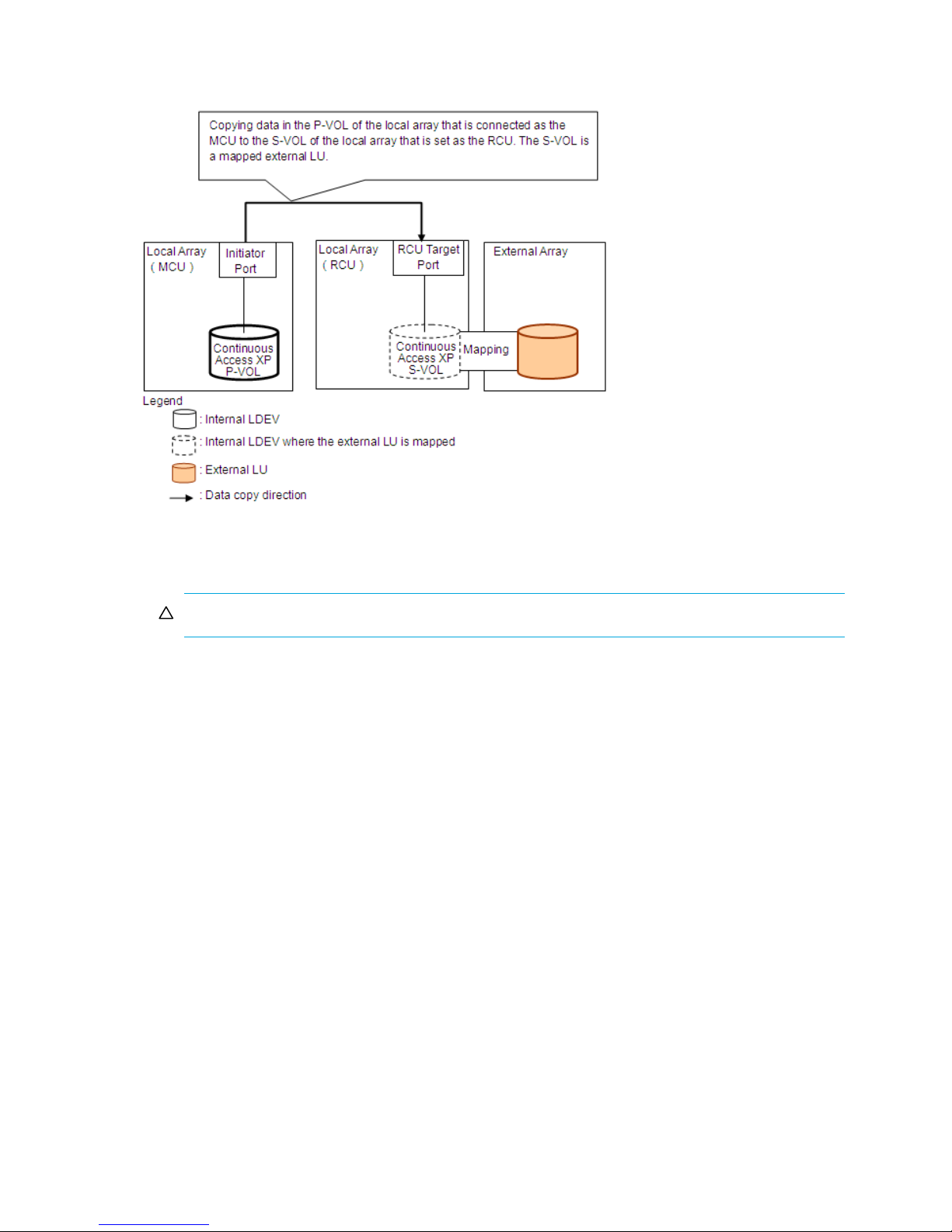
Continuous Access XP operations, see the HP StorageWorks Continuous Access XP user guide for the
XP12000/XP10000/SVS200.
Figure 15 Example of Continuous Access XP operations
1. Use External Storage XP to map a volume in the external array to an internal LDEV of the local
Continuous Access XP RCU array.
CAUTION: Set the IO Suppression mode to Disable.
Select the mapped volume’s emulation type as required. If you select an open-system emulation type
(such as OPEN-V), go to step 2. If you select a mainframe-system emulation type (such as 3390-3), go
to step 3.
For more information, see ”Mapping external LUs (Add LU)” on page 70.
2. If you set an open-system emulation type when mapping the volume, the mapped volume’s status
automatically becomes Normal. However, the volume-formatting process is not automatically executed.
To optionally format the mapped volume, use the Custom Volume Size (CVS) function. For instructions,
see the HP StorageWorks LUN Configuration and Security Manager XP user guide for the
XP12000/XP10000/SVS200.
Go to step 4.
3. If you set a mainframe-system emulation type when mapping the volume, the mapped volume’s status
becomes Blockade. To format the volume, use the CVS function. To restore the volume, perform the
Write to Control Blocks operation if you mapped a volume for which the data area has already been
zero-formatted on the external array side. For instructions, see the HP StorageWorks LUN Configuration
and Security Manager XP user guide for the XP12000/XP10000/SVS200.
Go to step 4.
4. Set the Continuous Access XP pair’s P-VOL and S-VOL.
Using external LUs for Continuous Access XP Journal operations
Figure 16 shows an example of using the external LU for Continuous Access XP Journal operations. The
mapped external LU is set as the Continuous Access XP Journal pair’s S-VOL, and the volume in the local
40 Preparing for External Storage XP operations
Page 41
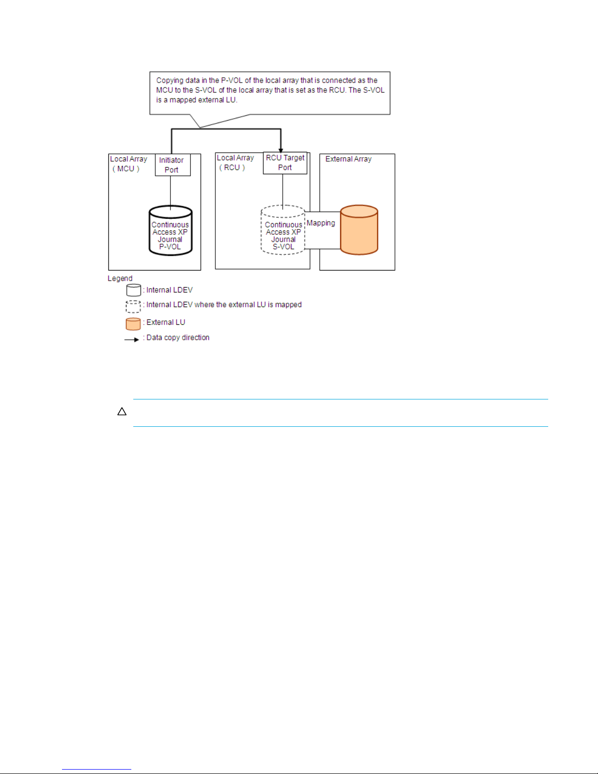
array that is connected as the MCU is set as the Continuous Access XP Journal’s P-VOL. For more
information, see the HP StorageWorks Continuous Access XP Journal user guide.
Figure 16 Example of Continuous Access XP Journal operations
1. Use External Storage XP to map the volume in the external array as an internal LDEV of the local array,
which is used as the RCU for Continuous Access XP Journal operations.
CAUTION: Set the IO Suppression mode to Disable.
Select the mapped volume’s emulation type as required. If you select an open-system emulation type
(such as OPEN-V), go to step 2. If you select a mainframe-system emulation type (such as 3390-3), go
to step 3.
For more information, see ”Mapping external LUs (Add LU)” on page 70.
2. If you set an open-system emulation type when mapping the volume, the mapped volume’s status
automatically becomes Normal. However, the volume-formatting process is not automatically executed.
To optionally format the mapped volume, use the Custom Volume Size (CVS) function. For instructions,
see the HP StorageWorks LUN Configuration and Security Manager XP user guide for the
XP12000/XP10000/SVS200.
Go to step 4.
3. If you set a mainframe-system emulation type when mapping the volume, the mapped volume’s status
becomes Blockade. To format the volume, use the CVS function. To restore the volume, use the Write to
Control Blocks operation if you mapped the volume for which the data area has already been
zero-formatted on the external array side. For instructions, see the HP StorageWorks LUN Configuration
and Security Manager XP user guide for the XP12000/XP10000/SVS200.
Go to step 4.
4. Set the Continuous Access XP Journal pair’s P-VOL and S-VOL.
Using external LUs for Business Copy XP operations
Figure 17 shows an example of using an external LU for Business Copy XP operations. The mapped
external LU is set as the Business Copy XP pair’s S-VOL, and the local array internal LDEV is set as the
External Storage XP user guide 41
Page 42

Business Copy XP pair’s P-VOL. For more information, see the HP StorageWorks Business Copy XP user
guide for the XP12000/XP10000/SVS200.
Figure 17 Example of Business Copy operations
1. Use External Storage XP to map a volume in the external array to an internal LDEV of the local array.
CAUTION: Set the IO Suppression mode to Disable.
Select the mapped volume’s emulation type as required. If you select an open-system emulation type
(such as OPEN-V), go to step 2. If you select a mainframe-system emulation type (such as 3390-3), go
to step 3.
For more information, see ”Mapping external LUs (Add LU)” on page 70.
2. If you set an open-system emulation type when mapping the volume, the mapped volume’s status
automatically becomes Normal. However, the volume-formatting process is not automatically executed.
To optionally format the mapped volume, use the Custom Volume Size (CVS) function. For instructions,
see the HP StorageWorks LUN Configuration and Security Manager XP user guide for the
XP12000/XP10000/SVS200.
Go to step 4.
3. If you set a mainframe-system emulation type when mapping the volume, the mapped volume’s status
becomes Blockade. To format the volume, use the CVS function. To restore the volume, perform the
Write to Control Blocks operation if you mapped a volume for which the data area has already been
zero-formatted on the external array side. For instructions, see the HP StorageWorks LUN Configuration
and Security Manager XP user guide for the XP12000/XP10000/SVS200.
Go to step 4.
4. Set the Business Copy XP pair’s P-VOL and S-VOL.
42 Preparing for External Storage XP operations
Page 43

3 Managing cache with external storage
XP disk arrays and storage virtualization systems use cache to facilitate host and internal I/O. When cache
mode is enabled, host I/O is accepted as quickly as it is received into the array’s cache where the
associated read or write is buffered. When cache mode is disabled, the array limits caching to one block
of read and write data per LDEV. Cache is also used by Data Mirroring and Data Migration products that
generate internal I/O to copy and move data between devices, such as:
• Business Copy XP
• Continuous Access XP software products
• Business Copy XP’s Snapshot feature
• Auto LUN XP
• XP Tiered Storage Manager
Having cache mode enabled for external storage devices that are slower than the XP array can provide a
performance benefit for some very specific and well-defined workloads, such as single-threaded sequential
access to a device. HP strongly recommends that you configure all external storage devices with cache
mode disabled unless you have determined that you meet these exact workload descriptions. When you
deviate from these workload descriptions, performance might not be as good as when cache is disabled.
Consult your HP account support representative to discuss the availability of tuning services for your XP
array.
This chapter explains how to balance cache usage between internal and external storage and protect the
potential benefits of using cache.
Guidelines for using cache with external storage
• Disable cache for external devices.
• Always disable cache mode for external LUs in an MSA or other storage array that is slower than
the XP or SVS200 external ports.
• Always disable cache mode for external LUs that are used by XP data replication or data migration
software (for example, P-VOLs, S-VOLs, pool volumes, and Auto LUN XP or XP Tiered Storage
Manager target volumes).
See ”Determining, setting, or changing the external LU cache mode” on page 43.
• Partition cache for external storage.
• Always put external volumes and internal XP volumes in separate cache partitions (CLPRs).
• Always partition external storage LUNs that are targets for XP data replication or migration software
(Business Copy XP, Continuous Access XP software products, Snapshot XP, Auto LUN XP, or XP
Tiered Storage Manager).
• Partition any external LUs that have cache enabled. External LUNs with cache enabled can use
large amounts of cache.
See ”Partitioning cache for external storage” on page 47.
• Consult HP account support representative to verify or change storage system modes. See ”Changing
storage system modes” on page 51.
Determining, setting, or changing the external LU cache mode
You set the cache mode when you define external LUs. HP strongly recommends that you set cache mode
to Disabled for external LUs. For instructions on mapping external LUs in a new configuration, see
”Mapping external LUs (Add LU)” on page 70.
CAUTION: Before you delete any LUs that you want to remap, carefully record necessary configuration
information. If you remap existing LUs with changed configuration settings (other than cache mode), you
can lose access to the LUs and the data they contain.
External Storage XP user guide 43
Page 44
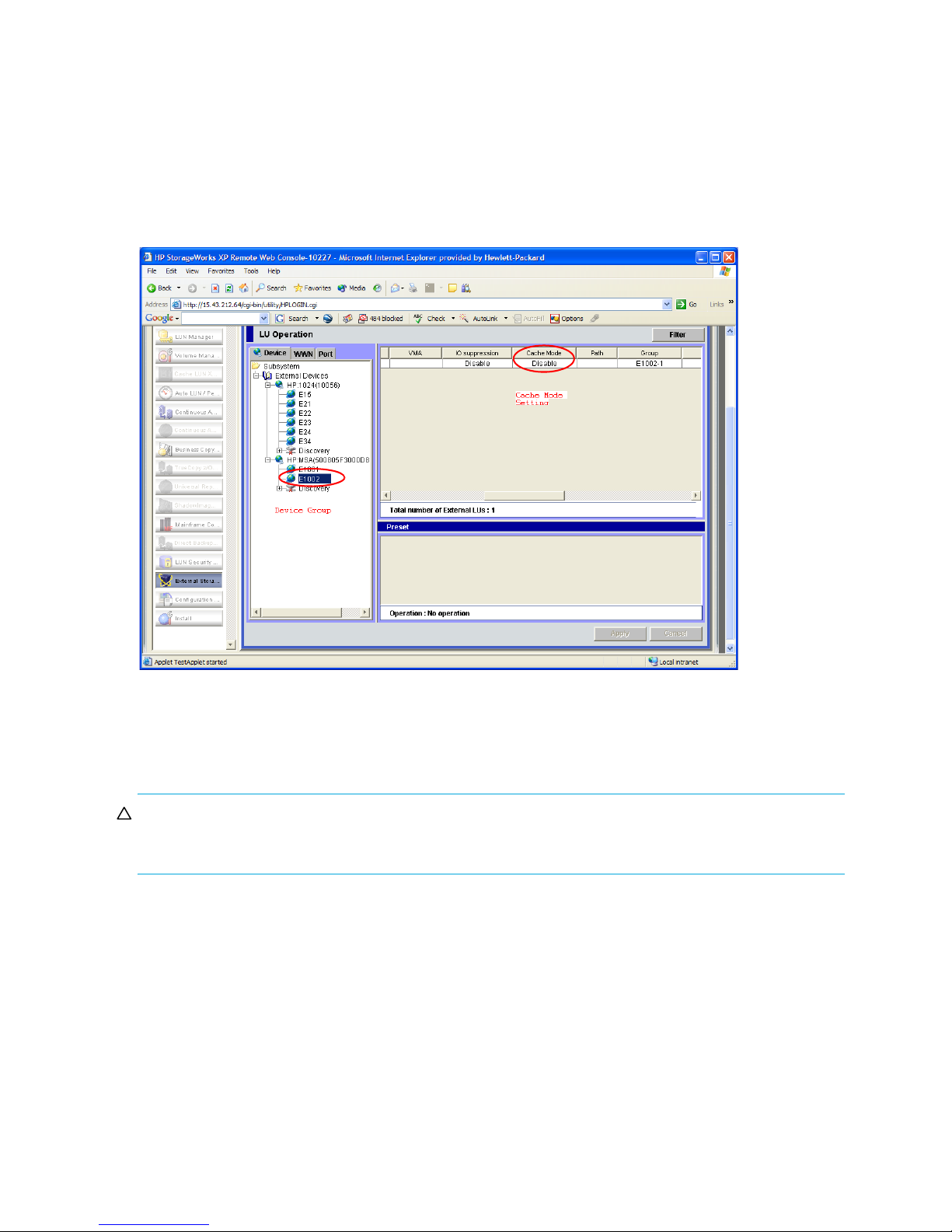
Determining if the cache mode is disabled
If you have an existing configuration and need to determine if your external LUs are configured with cache
mode disabled, follow this procedure:
1. In the XP Remote Web Console main pane, click the External Storage button in the left pane. The LU
Operation pane appears.
2. In the Device tree, select an external device group.
3. In the Device list, check the Cache Mode setting (Figure 18). If cache mode is enabled, you should
change it to Disabled.
Figure 18 LU Operation pane, Cache Mode setting
Changing the cache mode
If you need to change the cache mode for existing external LUs, you must delete and remap the external LU
path and definition.
CAUTION: Before you delete any LUs that you want to remap, carefully record necessary configuration
information. If you remap existing LUs with changed configuration settings (other than cache mode), you
can lose access to the LUs and the data they contain.
Collecting device information
Before you remap an external storage device, collect the following information for each device:
• LU number in the group
• Universal Unique ID (UUID)
• Path settings
• CVS settings
• Mapped location
• External group number
• CU:LDEV identifier
To collect each of these items:
44 Managing cache with external storage
Page 45

1. In the XP Remote Web Console main pane, click the External Storage button in the left pane. The LU
Operation pane appears.
2. To find the LU number and UUID, select an external device group in the Device tree (Figure 19).
The LU number appears in the LUN column in the Device list.
The UUID appears in the Characteristic2 column in the Device list.
Figure 19 LU Operation pane, LU number and UUID
3. To find the path settings, right-click the external LDEV in the Device list, and select Path Setting
(Figure 20).
Figure 20 LU Operation pane, Path Setting option
External Storage XP user guide 45
Page 46

The Path Setting pane appears (Figure 21).
Figure 21 Path Setting pane
4. To find the CVS settings, mapped location, external group number, and CU:LDEV identifier, right-click
the LDEV in the Device list on the LU Operation pane, and select LDEV Information (Figure 20). The
LDEV Information pane appears (Figure 22).
Figure 22 LDEV Information pane
Deleting and remapping the external LU
You must delete and remap each LU that needs the cache setting changed. Using the information recorded
in ”Collecting device information” on page 44, delete and remap each LDEV.
1. On the LU Operation pane, select the appropriate external LU group number in the Device tree.
2. In the Device list, right-click the external LU that you want to delete, and select Delete LU (Figure 20).
3. Click Apply.
4. Click either Yes or No. If you click Yes, skip the next step.
46 Managing cache with external storage
Page 47

5. Click OK in response to the warning message.
6. Click OK.
7. Remap the LU using all the previous settings except for the cache mode setting, which is disabled. See
”Mapping external LUs (Add LU)” on page 70.
NOTE: When scanning for devices to add, the order in which devices are discovered might be
different. The UUID is always the same for the same external device. Ensure that the UUID of the
device being remapped matches the UUID that was deleted for the same LU number.
8. Recheck to ensure that the same external storage LUs (identified by UUIDs) are now assigned their
original settings and the desired cache mode. If not, delete and remap the external LU again.
Partitioning cache for external storage
Separate cache partitions isolate the applications that are using XP arrays and storage virtualization
systems from the I/O dampening effects of a cache that is filling up with host and internal I/O for slower
external targets. HP requires separate cache partitions (CLPRs) for:
• External volumes and internal XP volumes, except for configurations where all external storage LUNs
have cache disabled and do not have any external storage devices using data mirroring or migration
products
NOTE: All HP 200 Storage Virtualization System volumes are external. Partition SVS200 cache
according to the other recommendations made in this section.
• External volumes that are used by XP data replication or data migration products, including Business
Copy XP, Continuous Access XP software products, Snapshot XP, Auto LUN XP, and XP Tiered Storage
Manager
• SVS200 source volumes and data copy or target volumes that have slower throughput
For example, Company A uses:
• XP10000 internal disks for database applications
• EVA3000 for backup applications
Cache can be partitioned for Company A as follows:
• CLPR0: XP10000 for Business Copy XP P-VOL
• CLPR1: EVA3000 for Business Copy XP S0VOL (external LU cache is disabled)
In another example, Company B uses the following storage tiers:
• Tier 1 is an XP12000 (6 TB of internal space) for P-VOLs
• Tier 2 is an EVA (20 TB) for P-VOLs and Business Copy XP S-VOLs
• Tier 3 is two MSA 1500 (10 TB) for the Business Copy XP S-VOLs
Cache can be partitioned for Company B as follows:
• CLPR0: 12 GB for the internal XP12000 P-VOL
• CLPR1: 4 GB for the EVA S-VOL and P-VOL
• CLPR2: 4 GB for the MSA S-VOL
• All external LU cache is disabled.
To partition cache for external storage:
1. Determine the number and size of the partitions you need (see page 48).
2. Create the partitions (see page 48).
External Storage XP user guide 47
Page 48

Determining the number and size of needed partitions
The minimum cache partition (CLPR) size is 4 GB. Determine the size you need for each CLPR being used
for external storage based on the total capacity of the assigned external volumes. Table 6 shows the
recommended cache sizes for external storage CLPRs on open systems. Table 7 shows the same
information for HP storage virtualization systems.
Table 6 Recommended individual CLPR cache size for external storage on open systems
External storage volume capacity assigned to CLPR Recommended cache size for CLPR
Less than 128,000 GB 4 GB
128,000 GB or more 8 GB
Table 7 Recommended individual CLPR cache size for external storage on HP storage virtualization
systems
External volume capacity assigned to CLPR CLPR0 Additional CLPRs
Less than 1 TB 4 GB 4 GB
1 TB <= capacity < 16TB 8 GB 4 GB
16 TB <= capacity < 20 TB 12 GB 4 GB
20 TB <= capacity < 128 TB 16 GB 4 GB
128 TB or more 24 GB 8 GB
Creating Cache partitions
Ensure the XP Disk/Cache Partition license is installed, you have Administrator authority on the array, and
you are in Modify mode in XP Remote Web Console. For more information about license keys and user
administration procedures, see the HP StorageWorks XP Remote Web Console user guide for
XP12000/XP10000/SVS200.
1. In XP Remote Web Console, click the Install button in the left pane.
2. Click the Partition Definition tab.
3. In the Cache Logical Partition tree, right-click SLPR0 (if you have additional storage partitions
configured, click the storage partition you want the CLPR to be created in), and select Create CLPR. The
new CLPR is added to the tree.
48 Managing cache with external storage
Page 49

4. Select the new CLPR in the tree, and change the size and other CLPR settings as needed (Figure 23).
Figure 23 Partition Definition pane
5. Click Apply for the changes to becomes effective.
6. Repeat step 3 through step 5 to define any additional CLPRs that you need.
7. To allocate external storage groups to a CLPR:
a. Double-click the SLPR.
b. Select the CLPR that you want to assign the external storage groups from (this will be CLPR0 if this is
the first time you are configuring partitioning).
External Storage XP user guide 49
Page 50

c. Select and right-click the external storage groups that you want to assign to another CLPR, and then
select Cut (Figure 24).
Figure 24 Partition Definition pane, Cut option
d. Right-click the CLPR that you want to assign the selected external storage groups to, and then select
Paste Parity Group (Figure 25). The selected external storage groups are added to the CLPR
resource list.
Figure 25 Partition Definition pane, Paste Parity Group option
e. Click Apply.
50 Managing cache with external storage
Page 51

f. Repeat step 7b through step 7e until you have allocated the external storage groups to the
appropriate CLPRs according to the plan you created after reading ”Partitioning cache for external
storage” on page 47.
For complete information about creating SLPRs and CLPRs, see the HP StorageWorks XP Disk/Cache
Par tition user guide.
Changing storage system modes
In addition to cache partitioning and cache modes, array system modes control LU cache usage.
HP service representatives can set the XP and SVS200 array system modes to adjust the array’s behavior.
For SVS200 arrays, no adjustments are needed.
For XP arrays, contact your HP account support representative to change the system modes if either of the
following is true:
• Your external LUs are used by XP or SVS200 data mirroring and data migration products such as
Business Copy XP, Snapshot XP, Auto LUN XP, or XP Tiered Storage Manager.
• You need cache enabled for external LUs.
External Storage XP user guide 51
Page 52

52 Managing cache with external storage
Page 53
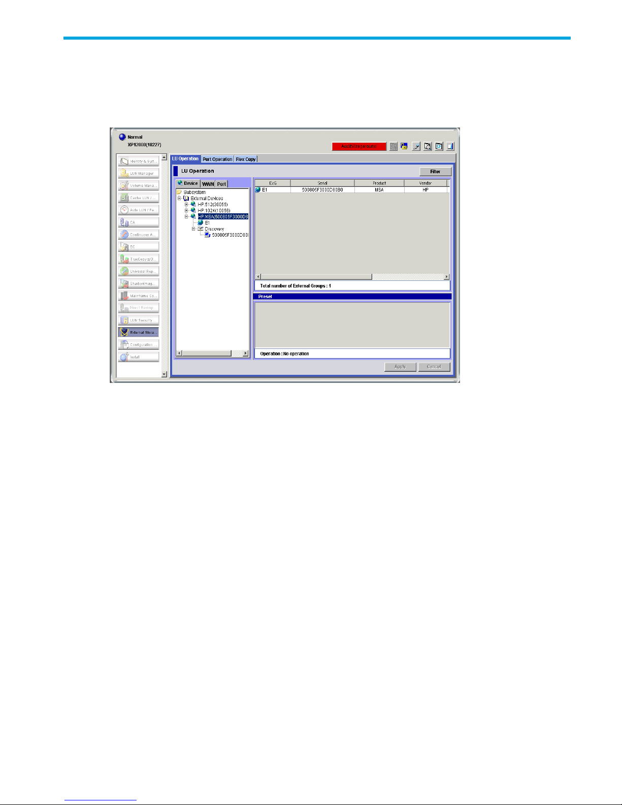
4 External Storage XP panes
External Storage XP operations involve the LU Operation and Port Operation panes. In addition to these
two panes, the Flex Copy pane is available if you licensed Flex Copy XP. When you select a tab, the
corresponding pane appears.
Figure 26 Panes for External Storage XP operations
External Storage XP user guide 53
Page 54

LU Operation pane
This pane appears when you start External Storage XP. Information about the external array appears on
the LU Operation pane. Use this pane to perform operations such as mapping external LUs and setting
alternate paths.
Device tree Device list Filter button
Preset list
Operation information area
Information area
Apply and Cancel buttons
Figure 27 LU Operation pane
• Device, WWN, and Port trees
Displays information in the Device, WWN, or Port list depending on the item selected in the tree.
Select the tab to display a tree. The following items can be selected in each tree:
• Items you can select in the Device tree include Subsystem (local XP), External Devices (arrays),
product names of connected external arrays, external LU group numbers, Discovery, and external
array WWNs. For more information, see ”Device tree” on page 55.
• Items you can select in the WWN tree include Subsystem, External Devices, product names of
connected external arrays, and external array WWNs. For more information, see ”WWN tree” on
page 58.
• Items you can select in the Port tree include Subsystem, External Devices, product names of
connected external arrays, and port numbers set to external ports. For more information, see ”Port
tree” on page 61.
• Filter button
Displays the Filter window, where you can restrict items displayed in the Device, WWN, and Port lists.
For more information, see ”Filter button” on page 63.
• Device, WWN, and Port lists
Displays information about the external array corresponding to the item selected in the Device, WWN,
or Port tree.
You can sort the list by displayed items. For example, to sort the list by LUN numbers, select LUN on
the list. For more information, see ”Device list” on page 56, ”WWN list” on page 59, and ”Por t list” on
page 61.
• Information area
Displays information about the contents of the Device, WWN, or Port
list, including:
54 External Storage XP panes
Page 55
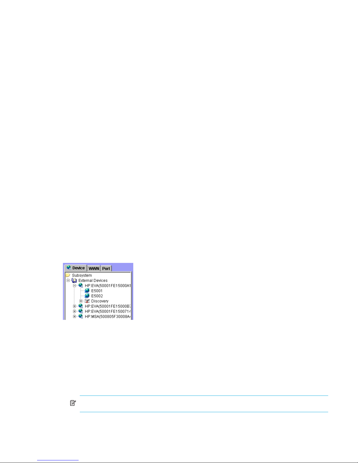
• Total number of Devices: Number of external LUs that are connected.
• Total number of External Groups: Number of external LU groups that are set.
• Total number of External LUs: Number of external LUs that are connected.
• Found WWNs: WWNs found when you clicked Discovery in the Device tree.
• Remain LUs: Number of external LU numbers available (out of 15,360), other than those that have
already been used.
• WWN Entry: Number of LUs that are currently used in the external array out of the maximum
theoretically possible (15,360).
Displayed in the format The number of connected ports/16,384 (the number of ports which can be
connected).
• Total number of WWNs: Number of external array ports that are connected.
• Total number of Paths: Number of paths set between the local array and external array.
• Preset list
Displays the contents of settings that were set by operations started on the LU Operation pane.
Contents displayed in the Preset list have not yet been applied to the local array. They are applied
when you click Apply. For more information, see ”Preset list (LU Operation pane)” on page 63.
• Operation information area
Displays operation information about settings in the Preset list, including:
• Operation: Setting operation name.
• Number of Objects in Preset: Number of rows displayed in the Preset list.
• Apply button
Applies pending operations in the Preset list to the local array. When operations are applied
successfully, they are removed from the Preset list. Otherwise, error messages appear and error
settings remain in the Preset list.
• Cancel button
Cancels all settings in the Preset list.
Device tree
Displays information about the external array connected to the external port.
Figure 28 Device tree
The Device list (right pane) changes according to the item selected in the Device tree.
• Subsystem
• External Devices
When selected, displays nothing in the Device list and displays the External Devices branch of the tree.
Subsystem is selected when you start External Storage XP and display the Device tree.
When selected, the Device list displays information about external arrays connected to external ports
that have been detected (supported).
NOTE: Not all types of detected external arrays are supported.
• Product name of the connected external array
External Storage XP user guide 55
Page 56

• External LU group number
• Discovery
• WWN of the external array
Device list
Displays information about external arrays corresponding to the item selected in the Device tree. You can
sort the list by displayed items. For example, to sort by LUN numbers, click LUN in the list.
When performing setting operations, the settings appear in the Preset list and the corresponding row in
the Device list appears in blue italics. For more information, see ”Preset list (LU Operation pane)” on
page 63.
Displays the name of the external array that can be connected using External Storage XP in the tree
under External Devices. When you select an external array’s product name, the Device list displays
detailed product information.
Displays user-assigned numbers in the branch under the external array’s product name, which is
connected to the local array and is already used. When you select an external LU group number, the
Device list displays information about external LUs registered in the selected group.
Appears in the branch under the product name of the external array connected to the local array.
When selected, External Storage XP searches for external array ports that can be connected, and
displays their WWNs.
If you select the WWN found by selecting Discovery in the Device tree, the Device list displays
information about external LUs that can be connected from the port indicated by the WWN.
Figure 29 Device list (external device selected in Device tree)
• Subsystem
Displays nothing. Subsystem is automatically selected when you select the Device tree.
• External Devices (for example, external storage group numbers currently defined for that external
device)
• Serial: Product serial number.
• Product: Product name.
• Vendor: Vendor name.
• Ex-Dev. Status: Status of the operation executed to the external array, or status of path connection.
External array’s status. Possible values: Normal, Unknown, Blockade, Warning, Checking, Cache
Destage, and Disconnect.
Table 8 External array status values
LU status Description
Normal LU status is normal.
Unknown LU status has yet to be ascertained.
Blockade I/O traffic to the LU is not permitted.
56 External Storage XP panes
Page 57

Table 8 External array status values (continued)
LU status Description
Warning FC path or paths have an abnormal status. Check the status of the paths.
Checking External Storage XP is verifying configuration information defined for FC paths.
Cache Destage External Storage XP is writing all data in the local array cache memory to the LU.
Disconnect Connection to external array or external LU was intentionally stopped using the
Disconnect Subsystem or Disconnect Volume command.
• LDEV Status: Mapped external LU’s status. Possible values: Normal, Unknown, Blockade, Warning,
and Format.
Table 9 Mapped external LU status values
LDEV status Description
Normal LDEV status is normal.
Unknown LDEV status has yet to be ascertained.
Blockade I/O traffic to the LDEV is not permitted.
Warning External LUs have abnormal status.
Format Volume is in the process of being formatted.
• Product name of the connected external array
• ExG: External LU group number. This appears when you group the LUs from one or more external
arrays under a common number.
• Serial: Product serial number.
• Product: Product name.
• Vendor: Vendor name.
• Ex-Dev. Status: Status of the operation executed on the external array, or status of the path
connection. Possible values: Normal, Unknown, Blockade, Warning, Checking, Cache Destage,
and Disconnect. For a description of these values, see Table 8.
• LDEV Status: Mapped external LU’s status. Possible values: Normal, Unknown, Blockade, Warning,
and Format. For a description of these values, see Table 9.
• External LU group number
• Characteristic: External LU’s identification number.
• Device: External LU’s device name.
• Capacity: External LU’s capacity in 512-byte blocks.
• Ex-Dev. info.: External array information. When the external array is an XP1024/XP128 or
TagmaStore Workgroup Modular Storage (WMS) array, an asterisk (*) appears.
• VMA: Information about the VMA setting by LUN Security XP Extension. When VMA is set for the
volume, an asterisk (*) appears.
• Alter. Path: Number of configured paths in the format The number of valid paths (the number of
primary alternate paths).
• IO Suppression: I/O Suppression mode: Enable or Disable
. For more information, see ”External LU
attributes set by mapping” on page 20.
• Cache Mode: Cache mode: Enable or Disable. For more information, see ”External LU attributes set
by mapping” on page 20.
• Path: When paths are set, an asterisk (*) appears.
• Group: External LU group number and reference number assigned to each LU in the external LU
group. External Storage XP automatically assigns reference numbers to LUs in the group when
external LUs are mapped. This appears in the format “external LU group number - reference
number of the LU in the group”.
External Storage XP user guide 57
Page 58

• Ex-Dev. Status: Status of the operation executed to the external array, or status of the path
connection. Possible values: Normal, Unknown, Blockade, Warning, Checking, Cache Destage,
and Disconnect. For a description of these values, see Table 8.
• LDEV Status: Mapped external LU’s status. Possible values: Normal, Unknown, Blockade, Warning,
and Format. For a description of these values, see Table 9.
• Progress: When Status is Cache Destage, displays the destaging process progress, from 1% to
100%.
• Characteristic2: External LU’s extended identifying information. This information is used for
identifying logical volumes in the EVA array. For more information, see ”Identifying logical volumes
of EVA arrays (using Characteristic 2)” on page 124.
• Discovery
• WWN: World Wide Name identifying the port in the external array that can be set.
• Serial: Product serial number.
• Product: Product name.
• Vendor: Vendor name.
• WWN of the external array
• LUN: LU number in the external array.
• Characteristic: External LU’s ID number.
• Device: External LU’s device name.
• Ex-Dev. info.: Information about the external array. When the external array is an SATA/FATA
drive, an asterisk (*) appears.
• VMA: Information about the VMA setting by LUN Security XP Extension. When VMA is set for the
volume, an asterisk (*) appears.
• Capacity: External LU’s capacity in blocks.
• Characteristic2: External LU’s extended identifying information. This information is used for
identifying logical volumes in the EVA array. For more information, see ”Identifying logical volumes
of EVA arrays (using Characteristic 2)” on page 124.
WWN tree
Displays information about items set in the Device tree. The contents of the WWN list changes depending
on the items selected in the WWN tree.
Figure 30 WWN tree
• Subsystem
When selected, displays nothing in the WWN tree. Subsystem is selected when you initially display
the WWN tree.
• External Devices
When selected, displays information about the external array connected to the external port in the
WWN list.
• Product name of the connected external array
When selected, displays the name of the external array for which the connection setting is already
completed in the tree under External Devices.
• WWN of the external array
When selected, displays WWNs identifying ports on the connected external array in the tree under
the name of the external array product.
58 External Storage XP panes
Page 59
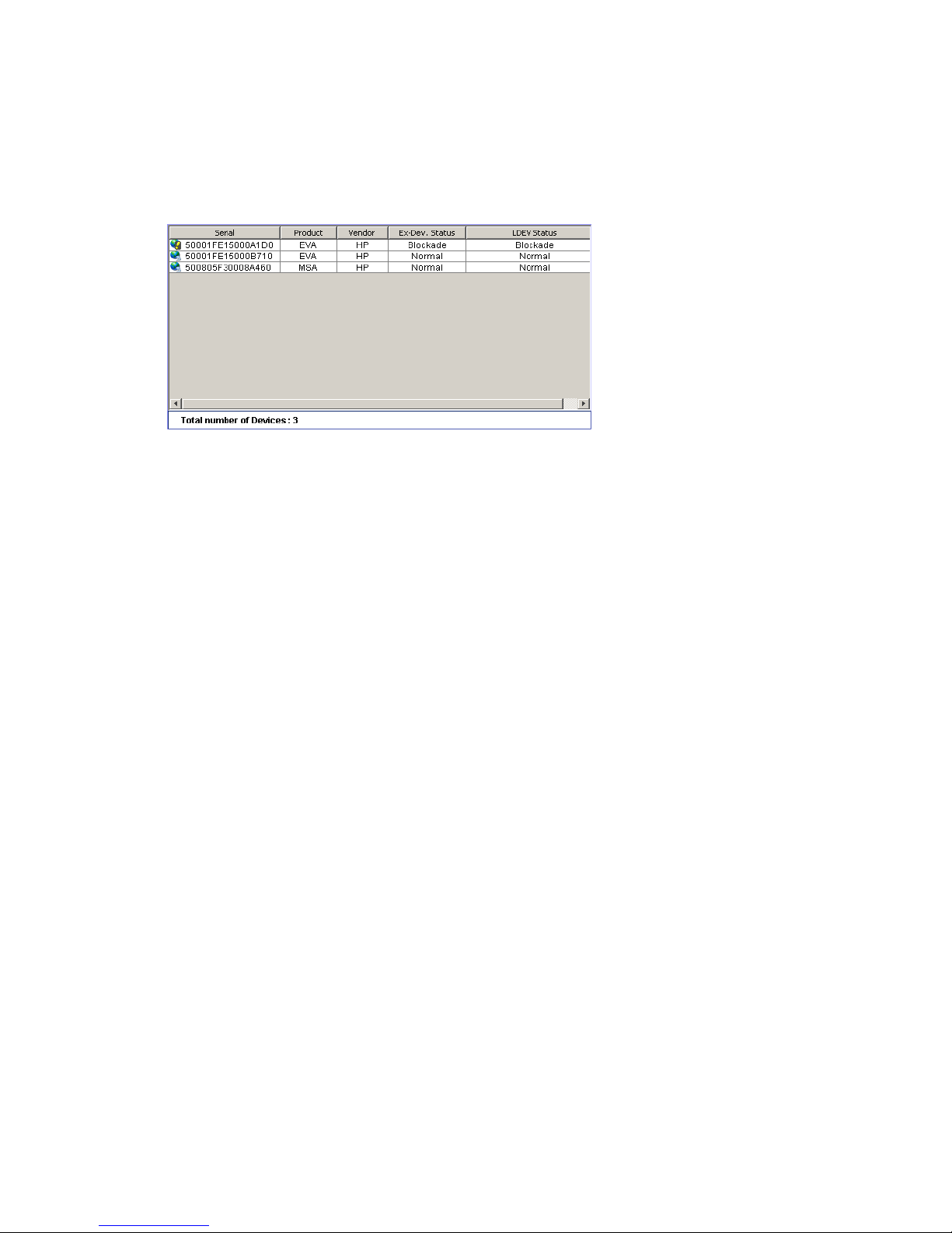
WWN list
Displays information about the connection status of the local array and external array corresponding to
the item selected in the WWN tree. You can sort the list by displayed items. For example, to sort by the
LUN number, select LUN on the list.
When performing setting operations, the settings appear in the Preset list and the corresponding row in
the WWN list appears in blue italics. For more information, see ”Preset list (LU Operation pane)” on
page 63.
Figure 31 WWN list (External Devices selected in the WWN tree)
The contents displayed in the WWN list changes depending on the item selected in the WWN tree.
• Subsystem
• External Devices
• Product name of the connected external array
When selected, displays nothing in the WWN tree. Subsystem is selected when you initially display
the WWN tree.
• Serial: Product serial number.
• Product: Product name.
• Vendor: Vendor name.
• Ex-Dev. Status: Status of the operation executed to the external array, or status of the path
connection. Possible values: Normal, Unknown, Blockade, Warning, Checking, Cache Destage, or
Disconnect. For a description of these values, see Table 8.
• LDEV Status: Mapped external LU’s status. Possible values: Normal, Unknown, Blockade, Warning,
or Format. For a description of these values, see Table 9.
• WWN: WWN identifying the port in the external array for which the connection setting is
completed.
• Path: Number of set paths.
• I/O TOV: Value specified as the timeout for I/O to the external LU.
• Qdepth: Number of Read/Write commands that can be issued (queued) to the external LU at one
time.
• Path Watch: Time period beginning when the connection of all paths to the external LU are down
and ending when the external LU is blocked.
• Mode: How alternate paths between the local array and external array work. Alternate path
modes include:
• Single: Uses only the path with the highest priority (primary path) to execute I/O to the external
LU. When an error occurs in the primary path, the path with the second highest priority is used.
• Multi: Uses all set paths at the same time to execute I/Os to the external LU, distributing the
work load.
• Status: Status of the path set in the port identified by the WWN. The highest emergency level status
appears when two or more paths are set. Statuses include:
• Normal: Path is normal.
• Unknown: Path status is unknown.
External Storage XP user guide 59
Page 60

• Blockade: Path is blocked.
• Disconnect: Connection to the external array or external LU was intentionally stopped using the
Disconnect Subsystem or Disconnect Volume command.
• Warning: There are paths whose status is not normal. Check the status of the paths.
• Checking: Process of checking the paths’ defined configuration informations is in progress.
• WWN of the external array
• Port: Port number of the local array connected to the port identified by the WWN selected in the
Port tree.
• WWN: WWN of the external array selected in the Port tree.
• LUN: External array’s LU number.
• Characteristic: External LU’s identification number.
• Group: External LU group number and reference number assigned to each LU in the external LU
group. External Storage XP automatically assigns reference numbers to LUs in the group when the
external LUs are mapped. This is displayed in the format of “external LU group number - reference
number of volume in the group”.
• Status: Status of the path configured by the port of the local array and the port of the external array
identified by the WWN. One of the following statuses is displayed:
• Normal: Path is normal.
• Unknown: Path status is unknown.
• Blockade: Path is blocked.
• External device setting changed: External array setting changed. For example, the path
definition was deleted, or the external array itself was replaced by another device.
• LDEV size reduced: External array’s volume capacity setting changed (volume capacity was
reduced).
• Not ready: External array replied NOTREADY.
• Illegal request: External array replied ILLEGALREQUEST.
• Command aborted: External array replied ABORTEDCOMMAND.
• Busy: External array is in BUSY status.
• LDEV reserved: External array is in Reserve status.
• Response error: External array is in blocked status caused by an abnormal reply (Response).
• Initiator port: External array’s port attribute changed to the initiator port.
• Unknown port: External array’s port attribute is unknown.
• Cannot detect port: Path was removed or external array’s port could not be found.
• Internal error: Program error occurred, or there is a logical contradiction.
• Timeout: Processing was retried because an abnormal reply (Response) was returned; however,
processing was stopped by a timeout.
• Standby: External array’s port is standing by. Port status is normal, but cannot receive I/O.
• Target error
: Port failures, such as controller blockade, are detected on the external array side.
• Checking: Process of checking the paths’ defined configuration information is in progress.
• Disconnect: Connection to the external array or external LU was intentionally stopped using the
Disconnect Subsystem or Disconnect Volume command.
• Unavailable: External array replied Unavailable. The external array demands to change the
connected port. Once the status becomes Unavailable, the primary path changes to the
alternate path that is in the Standby status. When the primary path changes, the status of the
path becomes Normal.
• Backoff: External array replied Backoff. The path status is waiting for recovery because a
temporary error occurred in the external array’s LU. Even if the primary path’s status becomes
Backoff, the primary path does not immediately change to the alternate path. After the error
recovery, the status becomes Normal. If the status cannot be recovered from the error, the path
status changes to the other status.
60 External Storage XP panes
Page 61

Port tree
• Characteristic2: External LU’s extended identifying information. This information is used for
identifying logical volumes in the EVA array. For more information, see ”Identifying logical volumes
of EVA arrays (using Characteristic 2)” on page 124.
When you select the Port tab, this tree displays information about ports that have the External attribute.
The contents displayed in the Port list changes depending on the item selected in the Port tree. For
instructions on setting the port attribute, see ”Setting a local array’s port attributes” on page 70.
Figure 32 Port tree
• Subsystem
When selected, displays nothing in the Port list. Subsystem is selected when you initially display the
Port tree.
• External
When selected, displays information about the port whose port attribute is set to External in the Port
list.
• Local array port number
When selected, displays connection information about the selected port in the Port list.
Port list
Displays information about the ports and paths of the local array or external array, depending on the item
selected in the Port tree. You can sort the list by displayed items. For instance, to sort the items by the port
number, select Port on the list.
Figure 33 Port list (External selected in Port tree)
The displayed contents changes depending on the item selected in the Port tree.
• Subsystem
When selected, displays nothing in the Port tree. Subsystem is selected when you initially display the
Port tree.
• External
• Port: Port of the local array with the port attribute is set to External.
• Path: Number of set paths.
• FLI_TOV: Wait time (in seconds) from the switch to FLOGI when the switch is connected. External
Storage XP automatically sets this value. You cannot change the value.
• PLI_TOV: Wait time (in seconds) of PLOGI to the external array when the switch is not connected.
External Storage XP automatically sets this value. You cannot change the value.
External Storage XP user guide 61
Page 62

• Margin: Additional wait time (in seconds) to FLI_TOV (FLOGI wait time) or PLI_TOV (PLOGI wait
time). External Storage XP automatically sets this value. You cannot change the value. As a result,
the sum of the FLI_TOV time and margin time, or the sum of the PLI_TOV time and margin time is set
as a total wait time.
• Status: Status of the path set in the port identified by the WWN. The highest emergency level status
is displayed when two or more paths are set. One of the following statuses is displayed:
• Normal: Path is normal.
• Unknown: Path status is unknown.
• Blockade: Path is blocked.
• Disconnect: Connection to the external array or external LU was intentionally stopped using the
Disconnect Subsystem ore Disconnect Volume command.
• Warning: There are paths whose status is not normal. Check the status of the paths.
• Checking: Process of checking the defined configuration information of the paths is in progress.
• Port number of the local array
• Port: Port number of the local array selected in the Port tree.
• WWN: WWN identifying the external array’s port. This port is connected to the local array port
selected in the Port tree.
• LUN: External array’s LU number.
• Characteristic: External LU’s identification number.
• Group: External LU group number and reference number assigned to each LU in the external LU
group. External Storage XP automatically assigns the reference numbers to LUs in the group when
the external LUs are mapped. This is displayed in the format of “external LU group number reference number of volume in the group”.
• Status: Status of the path configured by the port of the local array and the port of the external array
identified by the WWN.
• Normal: Path is normal.
• Unknown: Path status is unknown.
• Blockade: Path is blocked.
• External device setting changed: External array’s setting changed. For example, the path
definition was deleted or the external array itself was replaced by another device.
• LDEV size reduced: External array’s volume capacity changed (volume capacity was reduced).
• Not ready: External array replied NOTREADY.
• Illegal request: External array replied ILLEGALREQUEST.
• Command aborted: External array replied ABORTEDCOMMAND.
• Busy: External array is in BUSY status.
• LDEV reserved: External array is in Reserve status.
• Response error: External array is in blocked status caused by an abnormal reply (Response).
• Initiator port: External array’s port attribute changed to the initiator port.
• Unknown port
: External array’s port attribute is unknown.
• Cannot detect port: Path was removed or external array’s port could not be found.
• Internal error: Program error occurred, or there is a logical contradiction.
• Timeout: Processing was retried because an abnormal reply (Response) was returned; however,
processing was stopped by a timeout.
• Standby: External array’s port is standing by. The port status is normal, but cannot receive I/O.
• Target error: Port failures, such as controller blockade, are detected on the external array side.
• Checking: Process of checking the paths’ defined configuration information is in progress.
• Disconnect: Connection to the external array or external LU was intentionally stopped using the
Disconnect Subsystem or Disconnect Volume command.
• Unavailable: External array replied Unavailable. The external array demands to change the
connected port. Once the status becomes Unavailable, the primary path changes to the
62 External Storage XP panes
Page 63

• Characteristic2: External LU’s extended identifying information. This information is used for
Filter button
Displays the Filter window where you can restrict LUs displayed in the Device list.
Figure 34 Filter window
This window contains Enable and Disable options that control the display of unsupported devices. When
you select Enable, information about unsupported arrays appears in the Device tree and Device list.
Unsupported arrays are indicated by Unknown Devices in the Device tree and Device list.
alternate path that is in the Standby status. When the primary path changes, the status of the
path becomes Normal.
• Backoff: External array replied Backoff. The path status is waiting for recovery because a
temporary error occurred in the external array’s volume. Even if the primary path’s status
becomes Backoff, the primary path does not changed to the alternate path immediately. After
the error recovery, the status becomes Normal. If the status cannot be recovered from the error,
the path status changes to the other status.
identifying logical volumes in the EVA array. For more information, see ”Identifying logical volumes
of EVA arrays (using Characteristic 2)” on page 124.
The Disable option is selected by default.
Preset list (LU Operation pane)
Displays rows from the Device list that are about to be acted upon. You can apply settings to the local
array after checking the contents in the Preset list. Information displayed in the Preset list appears in blue
italics in the Device list. If you click Apply in the LU Operation pane, settings displayed in the Preset list
are applied to the local array. At that point, the contents of the Preset list disappear and the Device list
appears normally.
If you click Cancel in the LU Operation pane, all settings in the Preset list are canceled.
If settings in the Preset list contain errors, they are not applied to the local array even if you click Apply. In
that case, error messages appear and incorrect settings appear in the Preset list. In addition, error codes
appear in the Preset list.
NOTE: Depending on the type of errors that occur, identical error codes might be displayed for all errors
listed in the Preset list. In this case, check the status of settings to identify the source of the error.
When you right-click an item in the Preset list, the following commands appear:
• Detail
External Storage XP user guide 63
Page 64

Displays the Preset Detail window with detailed information about settings selected in the Preset list.
When an error code appears in the Preset list, a corresponding error message appears in this
window.
Figure 35 Preset Detail window (mapping operation)
• Delete
Cancels settings selected in the Preset list.
Port Operation pane
Use this pane to check port settings and set port attributes. This section describes items displayed in the
Port Operation pane. For instructions, see ”Setting a local array’s port attributes” on page 70.
Por t Operation tree
Por t Operation list
Preset list
Operation information area
Figure 36 Port Operation pane
• Port Operation tree
64 External Storage XP panes
Information area
Apply and Cancel buttons
Page 65

Displays information about the selected port in the Port list (right pane). You can select Subsystem, a
port attribute, or a port number. For more information, see ”Port Opera tion tree” on page 65.
• Port Operation list
Displays detailed information about ports selected in the Port Operation tree. For more information,
see ”Port Operation list” on page 66.
• Information area
Displays the total number of ports currently displayed in the Port Operation list (Total Number of Ports).
• Preset List
Displays rows corresponding to the ports that are about to be acted upon. The contents displayed in
the Preset list have not been applied to the local array yet. When you click Apply on the Port
Operation pane, actions designated in the Preset list are applied to the local array. For more
information, see ”Preset list (Port Operation pane)” on page 66.
• Operation information area
Displays operation information about settings displayed in the Preset list.
• Operation: Setting operation name.
• Number of Objects in Preset: Number of settings displayed in the Preset list.
• Apply button
Applies actions designated in the Preset list to the local array. When actions are applied without
error, they are removed from the Preset list. If errors occur, actions are not applied, error messages
appear, and the actions remain in the Preset list.
• Cancel button
Cancels all settings in the Preset list.
Port Operation tree
Displays ports in the connected local array. Contents displayed in the Port Operation list (right pane) varies
according to the item selected in the Port Operation tree (left pane).
Figure 37 Port Operation tree
• Subsystem
When selected, displays nothing in the Port Operation list. Subsystem is selected when you initially
display the Port Operation pane.
• External
When selected, displays ports designated a external ports, which is the port attribute used for External
Storage XP. External ports do not have High Speed mode.
• Initiator
When selected, displays ports designated as an initiator (sending) port (used for Continuous Access XP,
TrueCopy for z/OS, Continuous Access XP Journal, Universal Replicator for z/OS, and so on).
• Target
External Storage XP user guide 65
Page 66

When selected, displays ports designated as host target ports (used for host connect).
• RCU Target
When selected, displays ports designated as an RCU target (receiving) port (used for Continuous
Access XP, TrueCopy for z/OS, Continuous Access XP Journal, Universal Replicator for z/OS, and so
on).
• Por t number
Displays ports assigned to each port attribute in the branch below each port attribute. External
Storage XP uses ports set to external.
Port Operation list
Displays ports in the local array that External Storage XP can use or set. The port information displayed
corresponds to the item selected in the Port tree.
You can sort the list by attribute. For example, to sort by port numbers, click Port on the list.
Rows corresponding to ports that are about to be acted upon appear in the Preset list, and the
corresponding row in the Port Operation list appears in blue italics.
Figure 38 Port Operation list
• Port
Port number.
• Attribute
Port attribute. External ports are used for connecting to the external array.
• PCB Mode
Port’s PCB mode. External ports do not have High Speed mode.
• FLI_TOV (Fabric Login Timeout Value)
Maximum time allowed (in seconds) for an external array to perform a fabric login after being
connected to a switch. This value is preset and cannot be changed.
• PLI_TOV (Port Login Timeout Value)
Maximum time allowed (in seconds) for the external array to perform a port login after being
connected. This value is preset and cannot be changed.
• Margin
The sum of the FLI_TOV and PLI_TOV values.
Preset list (Port Operation pane)
This list displays rows from the Port Operation list that are about to be acted on. Check the contents of the
Preset list before applying them to the local array. Contents displayed in the Preset list appear in blue
italics in the Port Operation list. When you click Apply in the Port Operation pane, actions designated in
the Preset list are applied to the local array and the contents of the Preset list disappear.
If you click Cancel in the Port Operation pane, all designated actions in the Preset list are canceled.
If settings in the Preset list contain errors, actions are not applied to the local array even if you click Apply.
In that case, error messages appear, incorrect settings appear in the Preset list, and error codes appear in
the Preset list.
When you right-click a setting in the Preset list, the following commands appear:
• Detail
66 External Storage XP panes
Page 67

Displays the Preset Detail window with detailed information about actions selected in the Preset list.
When an error code appears in the Preset list, a corresponding error message appears in the Preset
Detail window.
Figure 39 Preset Detail window (changing port attribute)
• Delete
Cancels actions selected in the Preset list.
External Storage XP user guide 67
Page 68

68 External Storage XP panes
Page 69

5Configuring external LUs
Use External Storage XP to perform operations to access external LUs, such as setting the port attribute to
the external port and mapping the external LU as the internal LDEV.
This chapter describes procedures for using External Storage XP to configure external LUs.
Overview of configuring external LUs
Figure 40 shows an example of using External Storage XP to configure external LUs.
Figure 40 Overview of configuring external LUs
The following is the general procedure for configuring external LUs.
1. Configure the port and system parameters for the external array. For instructions, see the external LU’s
documentation, ”Setting an external array’s port” on page 70, and ”Notes on connecting external
arrays” on page 113.
2. Start External Storage XP operations. For instructions, see the HP StorageWorks Command View XP
user guide for XP Disk Arrays or the HP StorageWorks XP Remote Web Console user guide for
XP12000/XP10000/SVS200.
3. Set the external array port attribute to External. For instructions, see ”Setting a local array’s port
attributes” on page 70.
4. Perform the Discovery operation.
In the Device tree on the LU Operation pane, select an external array, and select Discovery (see
”Mapping external LUs (Add LU)” on page 70).
NOTE: To perform Discovery operations, Command View XP or XP Remote Web Console must be
in Modify mode.
5. Display the LU Operation pane, right-click the external LU to be mapped as an internal LDEV in the
Device list, and select Add LU or Add LU (Auto). The Add LU or Auto Map Setting pane appears.
External Storage XP user guide 69
Page 70

6. Use the Add LU or Auto Map Settings pane to map the external LU as an internal LDEV (”Mapping
external LUs (Add LU)” on page 70).
7. If you select a mainframe emulation type on the Add LU pane, use Volume Manager to reformat the
volume or perform the Write to Control Blocks operation. For instructions, (see the HP StorageWorks
LUN Configuration and Security Manager XP user guide for the XP12000/XP10000/SVS200.
8. Define alternate paths between the external array or mapped LU and the local array. For instructions,
see ”Defining alternate paths” on page 87.
9. Use LUN Manager to define paths. For instructions, see the HP StorageWorks LUN Configuration and
Security Manager XP user guide for the XP12000/XP10000/SVS200.
Setting an external array’s port
This section describes the procedure for setting the external array’s port. For more information, see the
external array’s documentation.
1. Set the topology information for the connection configuration.
2. Set the data transfer speed for the configuration.
3. Set the system parameters. For more information about system parameters for specific external arrays,
see ”Notes on connecting external arrays” on page 113.
4. Define the port’s LUN.
Setting a local array’s port attributes
The attribute of any port used for External Storage XP must be set to External.
NOTE: Only ports in SLPR0 can be set as external ports.
1. Select the Port Operation tab.
2. In the Port Operation list, select the port.
To set multiple ports at one time to External, select all the ports.
3. Right-click, and select Change to External.
In the Port Operation list, the selected port’s attribute changes to External, and the selected port’s row
appears in blue italics. Rows to be affected appear in the Preset list. To check setting details, right-click
the setting in the Preset list, and select Detail. To cancel settings, right-click the setting in the Preset list,
and select Delete.
4. Click Apply. A confirmation message appears.
5. Click OK. The port attribute setting is applied to the local array, and the new setting appears in the Port
Operation list.
If an error occurs, the failed setting and an error code appears in the Preset list. To view error
messages, right-click the failed row, and select Detail.
6. Set the topology for the connection configuration.
When an FC switch is connected, set Fabric to Enable. When a switch is not connected, set Fabric to
Disable, and specify FC-AL. Set Connection according to the actual connection configuration. For more
information about setting the topology, see the HP StorageWorks LUN Configuration and Security
Manager XP user guide for the XP12000/XP10000/SVS200.
7. Set the data transfer speed to Auto Negotiation.
Mapping external LUs (Add LU)
After setting the port used for External Storage XP to External, map the external LU as an internal LDEV.
If you mapped the external LU and previously set the VMA of LUN Security XP Extension in that volume, the
former VMA setting is overwritten when you map the volume again. However, if LUN Security XP Extension
is not installed when you remap the volume, the volume with the VMA setting cannot be mapped.
70 Configuring external LUs
Page 71

Mapping external LUs individually (Add LU)
This section describes mapping operations starting with the Add LU command. Use the Add LU (Figure 41),
Select Paths (Figure 42), SSID (Figure 45), and Set SSID (Figure 46) panes for mapping external LUs
individually.
NOTE: Before mapping the external LU, ensure that no other applications (such as RAID Manager XP)
that use the command device are executing. Stop any applications that are executing.
CU list
CU:LDEV list
LDEV map
Figure 41 Add LU window
• Vendor
External array’s vendor.
• Product
External array’s product name.
• Serial
External array’s product serial number.
• WWN
World Wide Name of the external array port used for connecting to the local array.
• LUN
LU number of the external LU.
• Device
External LU’s device name.
• Ex-Dev. info.
External array information. When the external array is an XP1024/XP128 or TagmaStore Workgroup
Modular Storage (WMS) array, an asterisk (*) appears.
• VMA
Information about the VMA setting of LUN Security XP Extension. If you mapped the external LU and
previously set the VMA of LUN Security XP Extension, an asterisk (*) appears. If LUN Security XP
Extension is not installed when you remap the volume, you cannot map the volume with the VMA
setting.
• Capacity
External LU’s capacity in blocks.
• Characteristic
External Storage XP user guide 71
Page 72

External LU’s identification number.
• Characteristic2
External LU’s extended identifying information. This information is used for identifying logical volumes
in the EVA array. For more information, see ”Identifying logical volumes of EVA arrays (using
Characteristic 2)” on page 124.
• ExG (1-16384)
Group number of the connected external LUs. You can specify any decimal value from 1 to 16384. The
E displayed outside the text box is the capital letter of the external LU group.
• Emulation Type
Emulation type of the mapped external LU (from the XP12000/XP10000/SVS200 perspective) (see
”External LU attributes set by mapping” on page 20).
If you clear the Except OPEN-V check box, OPEN-V and available mainframe emulation types appear
in the list.
If you select the Except OPEN-V check box, open-system emulation types other than OPEN-V appear in
the list. To map the external LU as an open-system volume, define the emulation type to use for the
mapped LU as OPEN-V or another type. To map the external LU as an open-system volume using an
emulation type other than OPEN-V, select the Except OPEN-V check box.
If you plan to use the mapped external LU for a Flex Copy XP pair, you must select OPEN-V.
When the external LU to be mapped has the VMA setting, you must select OPEN-V.
• LDEV Capacity
Default capacity of the emulation type selected in the Emulation Type box. When the external LU’s
capacity is larger than the capacity displayed in LDEV Capacity, the external LU is divided into the
displayed capacity, and multiple LDEVs are created.
• LDEV
Number of LDEVs created at mapping. By default, the maximum number of LDEVs corresponding to the
capacity supported by the emulation type specified in the Emulation Type box appears. When the
external LU to be mapped has the VMA setting, you can select only 1.
• IO Suppression
Mapped external LU’s IO Suppression mode (for OPEN-V emulation only) (see ”External LU attributes
set by mapping” on page 20).
To suppress I/O operations from hosts (by way of the XP12000/XP10000/SVS200) to the mapped
external LU or use the mapped external LU for a Flex Copy pair, select Enable.
If you do not suppress I/O from hosts to the mapped external LU, select Disable (for example, for use
with External Storage XP).
If you set the emulation type to something other than OPEN-V, IO Suppression mode is automatically set
to Disable.
When the external LU to be mapped has the VMA setting, IO Suppression mode is automatically set to
Disable.
CAUTION: To use the mapped external LU for the software products other than Flex Copy XP (such
as Cache LUN XP, Auto LUN XP, Continuous Access XP, Continuous Access XP Journal Business
Copy XP, or Snapshot XP), set IO Suppression mode to Disable.
CAUTION: To set IO Suppression mode to Disable, External Storage XP must be installed.
CAUTION: To set IO Suppression mode to Enable, Flex Copy must be installed.
• Cache Mode
72 Configuring external LUs
Page 73

Specifies if the write I/O from the host is propagated synchronously (cache disabled) or asynchronously
(cache enabled) to the external storage device (see ”External LU attributes set by mapping” on
page 20).
HP recommends that you set cache mode to Disable.
NOTE:
• If you set the IO Suppression mode to Enable, Cache Mode becomes Disable.
•If you select Disable, Cache LUN XP’s bind mode cannot be set.
• If you specified a mainframe-system emulation type for the mapped LU, host I/O is always
propagated asynchronously to the external LU regardless of the Cache Mode setting.
• Alternate Path
Number of alternate paths automatically set when mapped. Value can be from 0 to 7. Default is 1.
CAUTION: If the specified number of alternate paths cannot be set, an error appears in the Preset
list.
• CLPR (see ”External LU attributes set by mapping” on page 20)
When cache memory is partitioned using XP Disk/Cache Partition, you can select the CLPR used to
access the mapped volume from the list. The SLPR number that the selected CLPR belongs to appears on
the right of the list. However, if you select a mainframe emulation type in Emulation Type, you can only
select CLPRs belonging to SLPR number 0. The Limited check box appears on the right of the SLPR
number. To display only CUs defined for the selected SLPR, select the Limited check box. To display all
CUs, regardless of the SLPR, clear the check box. By default, the Limited check box is selected.
• Select Paths button
Displays the Select Paths pane (Figure 42). Use the Select Paths pane to select paths as candidates for
primary and alternate paths and select paths that cannot be set to primary and alternate paths. By
default, all paths with a confirmed connection status of normal are set as candidates for primary and
alternate paths. However, to set a specific path as the alternate path, use the Select Paths pane to
specify candidates for alternate paths. Alternate paths are automatically set from the candidates, as
many as the number set in Alternate Path.
CAUTION: If you do not set alternate paths on the Select Paths pane, alternate paths are
automatically set according to the WWN selected in the Device tree on the LU Operation pane
when you started the Add LU operation.
• Clear button
Resets all the external LU’s attributes.
• CU list
CU number of the local array to which you want to map the external LU. Select the CU number from the
list. When the Limited check box is selected, the selection range is limited to the CU belonging to the
SLPR displayed in CLPR.
• Linear button
Maps all external LUs listed in the CU:LDEV list at one time. When you click Linear and then select an
internal LDEV on the LDEV map, External Storage XP automatically selects from the LDEV map the same
number of internal LDEVs as external LUs listed in the CU:LDEV list, starting at the internal LDEV you
selected. The LDEV numbers of the selected internal LDEVs are sequential. When Interval is set,
mapping is done at the specified number of intervals. To map one external LU to another internal LDEV
after mapping the external LU automatically using the Linear button, release the Linear button, and map
the external LU individually.
• CU:LDEV list
External Storage XP user guide 73
Page 74

Displays the XP12000/XP10000/SVS200 CU:LDEV numbers of external LUs mapped as internal
LDEVs. (N/A) (Not Assigned) means the external LUs are not yet mapped as internal LDEVs. To map an
external LU as an internal LDEV, select an external LU with (N/A) in the CU:LDEV list. To map all external
LUs in the CU:LDEV list at one time, use the Linear button.
• Interval
If you select two or more volumes in the CU:LDEV list or click Linear for mapping, you can select the
interval that arranges each volume. Values can be from 0 to 255. Default is 0.
For example, if you select three volumes in the CU:LEDV list, set Interval to 255, and map the first
volume to CU:LDEV number 00:01, the second and third volumes are mapped to 01:01 and 02:01,
respectively.
• LDEV map
Each cell in the map represents an internal LDEV. Select a cell for the internal LDEV on the map. The
selected cell turns blue, and the selected LDEV is mapped to the external LU. internal LDEVs that have
been mapped appear in gray, and those not yet mapped appear in white.
• Previous and Next buttons
If you select multiple external LUs in the Device list, click Previous to map the external LU in the row just
above the currently selected external LU. Click Next to map the external LU in the row just below the
currently selected external LU.
• OK button
Displays the SSID window, where you can continue with the next step of the mapping operation. If the
SSID setting is not necessary, the Add LU window closes, and the LU Operation pane appears.
The OK button is available when mapping on the Add LU window is complete.
• Cancel button
Cancels all mapping operations, closes the Add LU window, and returns to the LU Operation pane.
Select Paths pane
All paths that can be set as primary and alternate paths appear in the Select Paths pane. To set a specific
path as the alternate path, use the Select Paths pane to specify candidates for the alternate paths.
If you let alternate paths be automatically set with all connected normal paths as candidates, you can omit
the setting operation on the Select Paths pane.
Figure 42 Select Paths pane
• Port
Local array ports. You can set alternate paths for the selected port.
• Selected Paths
External array port for which you can set the alternate path connecting to the local array port selected
in the Port list. By default, all ports that can be set as alternate paths appear. The WWN identifying the
external array port appears. If the primary path and as many alternate paths as you set in Alternate
Path in the Add LU pane cannot be set with the paths selected in Selected Paths, an error occurs and
appears in the Preset list.
74 Configuring external LUs
Page 75

• Unselected Paths
Ports excluded from being candidates for the ports setting the primary and alternate paths appear
among the external array ports that can be set as the primary and alternate paths. WWNs identifying
the external array ports appear in the list.
• Set button
If you select the port (external array WWN) you want to set as the candidate for the primary and
alternate paths in Unselected Paths, and click Set, the selected WWN moves to Selected Paths.
• Release button
If you select the port (external array WWN) you want to exclude from the list of candidates for the
primary and alternate paths in Selected Paths, and click Release, the selected WWN moves to
Unselected Paths.
• OK button
Saves settings in the Select Paths pane, and closes the pane.
• Cancel button
Cancels all settings in the Select Paths pane, and closes the pane.
To map an external LU as an internal LDEV individually:
1. Select the LU Operation tab. The LU Operation pane appears.
2. In the Device tree, select Discovery. WWNs appear in the tree indicating external array ports that can
be connected.
3. In the Device tree, select the port (WWN) you want to connect from the WWNs listed in the Device.
External LUs that can be connected from the external array port (WWN) selected in the tree appear in
the Device list.
4. Right-click the external LU you want to map as an internal LDEV in the Device list, and select Add LU.
The Add LU window appears.
5. Select the internal LDEV that is mapped to the external LU selected in the Device list on the Add LU
window. Enter the following items in the Add LU window:
a. In the ExG box, select an external LU group number.
b. From the Emulation Type list, select an emulation type.
c. In the LDEV box, select the number of volumes to create.
d. Select the IO Suppression mode.
e. Select the Cache Mode.
f. In the Alternate Path box, select the number of alternate paths that are automatically set.
g. In the CLPR box, select the CLPR to be used. To limit the CU selection range, select the Limited check
box.
h. In the CU# list, select the CU number.
i. To map two or more external LU at the same time, select the interval that arranges each volume in
the Interval box.
j. Select one or more external LUs, and select one or more cells in the LDEV map.
When selecting two or more external LUs in the CU:LDEV list, if you select one cell of the internal
LDEV number in the LDEV map, the number of cells automatically selected is the same as the
number external LUs selected in the CU:LDEV list with the selected internal LDEV first. When Interval
is set, mapping is done at intervals of the specified number.
• To map all the external LUs displayed in the CU:LDEV list at one time:
Click Linear, and select an internal LDEV on the LDEV map. The same number of internal LDEVs
as the external LUs listed in the CU:LDEV list are automatically selected on the LDEV map
External Storage XP user guide 75
Page 76
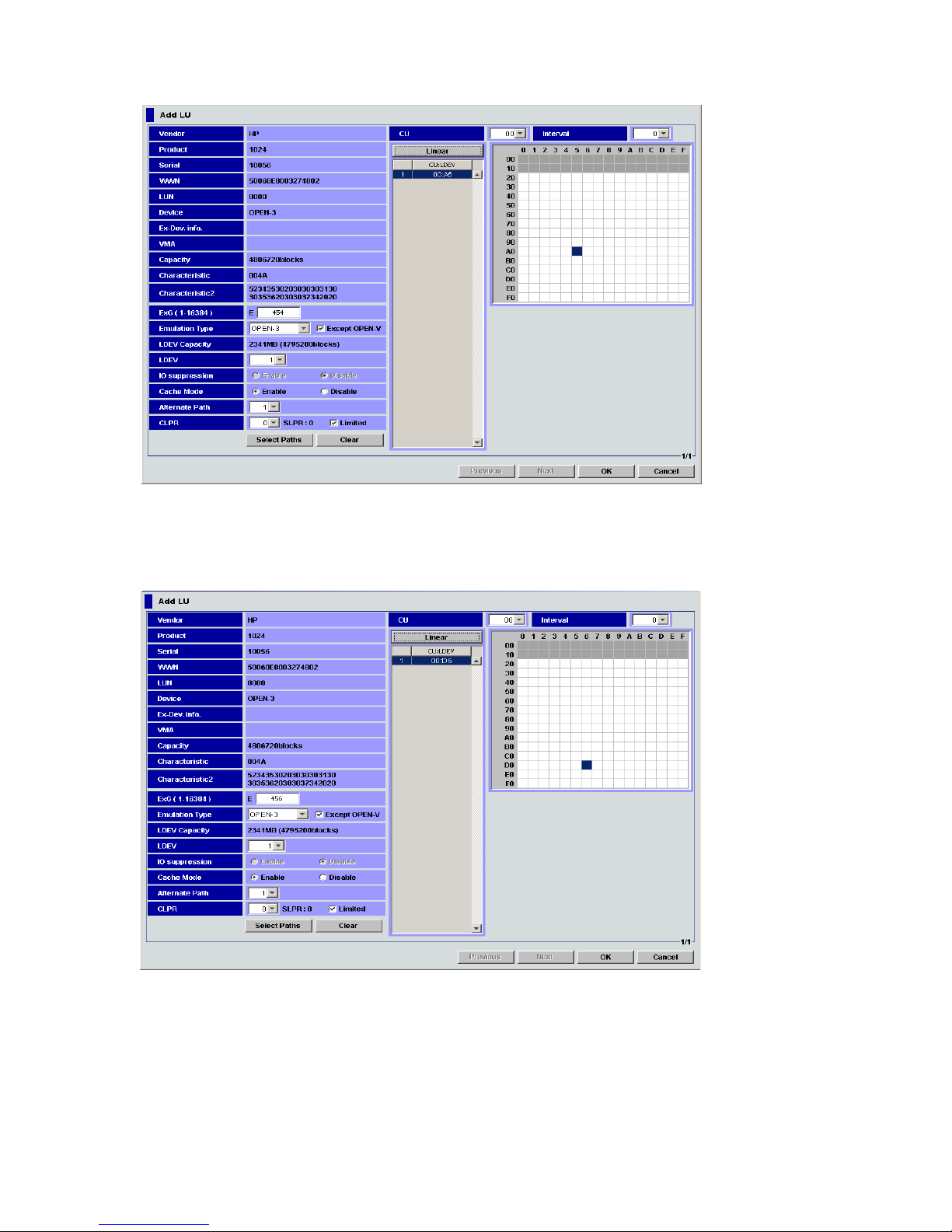
following the internal LDEV you selected (Figure 43). The LDEV numbers of the selected XP LDEV
are in a series. When Interval is set, the mapping is done at the specified interval.
Figure 43 Add LU pane (mapping using the Linear button)
• To map one external LU to another internal LDEV:
After automatically mapping the external LU using the Linear button, release the Linear button,
and map the external LU individually (Figure 44)
.
Figure 44 Add LU pane (mapping with the Linear button released
6. If you do not want to automatically set primary and alternate paths, but want to specify paths set as
candidates for primary and alternate paths, click Select Paths. The Select Paths pane appears.
To automatically set alternate paths, go to step 9.
7. Select the path and exclude it from the list of candidates for primary and alternate paths in the Select
Paths pane. For more information, see ”Select Paths pane” on page 74.
8. Click OK. The Add LU pane appears.
9. When all settings are complete on the Add LU window, click OK.
76 Configuring external LUs
Page 77
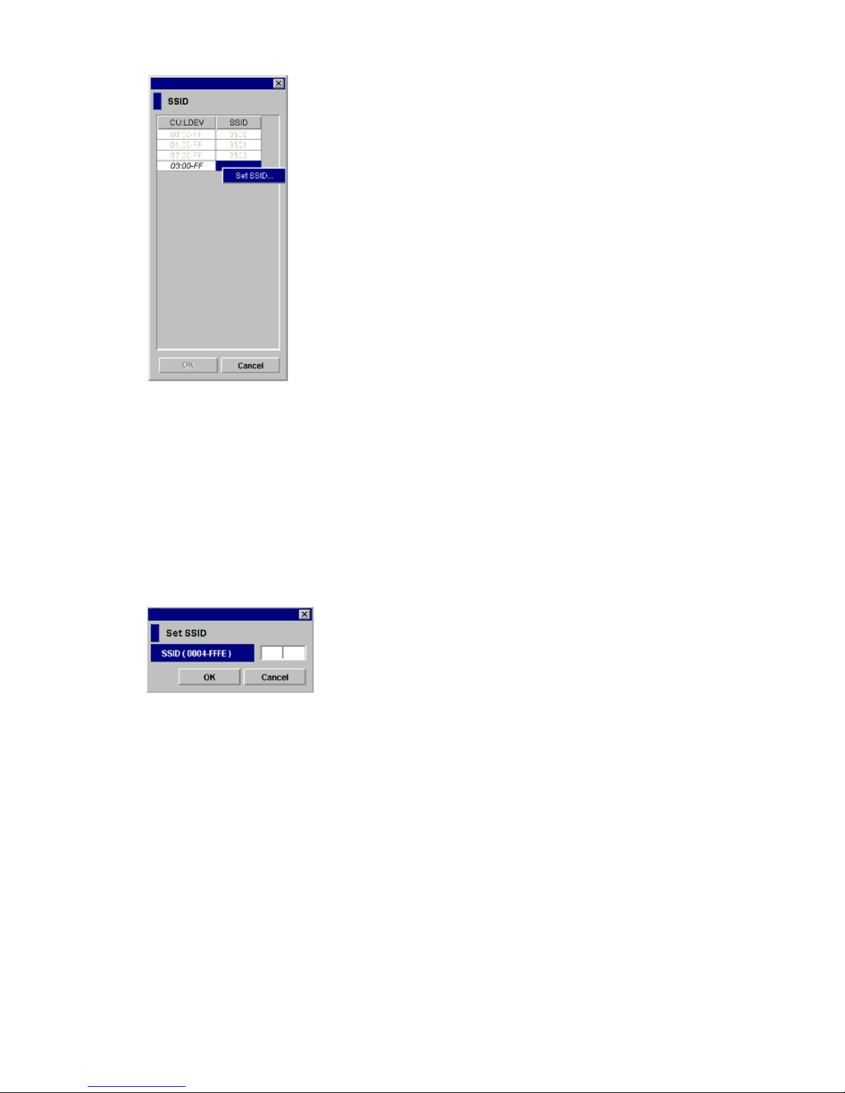
• If you need to set the SSID, the SSID window appears. Go to step 10.
Figure 45 SSID window
• If the SSID setting is not necessary, the Add LU window closes, and the LU Operation pane
appears. Settings appear in blue italics in the Device tree and Device list. Contents specified in the
Add LU window appear in the Preset list. To check setting details, right-click the setting in the Preset
list, and select Detail. To cancel settings, right-click the setting in the Preset list, and select Delete.
Go to step 13.
10.If you need to set an SSID to the mapped internal LDEV, the SSID pane appears. When storage is
partitioned using XP Disk/Cache Partition, select the SLPR number in the SLPR box. If you select the
Limited check box and select the SLPR number, you can set only SSIDs that can be used for the selected
the SLPR. If you do not select the Limited check box, you can set the SSID from all unused SSIDs
regardless of the selected SLPR number. Right-click the CU:LDEV number on the SSID pane, and select
Set SSID. The Set SSID window appears.
Figure 46 Set SSID window
11.Enter the SSID. If you selected the Limited check box on the SSID window, only SSIDs that can be used
in the SLPR selected on the SSID pane appear in the drop-down list. If you did not select the Limited
check box on the SSID pane, all unused SSIDs appear in the list, regardless of the selected SLPR. You
can enter 0x0004 to 0xFFFE as an SSID.
12.Click OK. The Set SSID window closes, and the LU Operation pane appears.
Settings appear in blue italics in the Device tree and Device list and also appear in the Preset list. To
check setting details, right-click the setting in the Preset list, and select Detail. To cancel settings,
right-click the setting in the Preset list, and select Delete.
13.Click Apply. A confirmation message appears.
If you already stopped the application, go to step 14. If you have not stopped the application, click
Cancel to close the message pane, stop the application, and retry the operation.
14.Click OK. A confirmation message appears.
15.Click OK. The mapping set in the Add LU window is applied to the local array, and the specified
contents appear in the Device list.
If errors occur during the external LU mapping operation, failed settings and error codes appear in the
Preset list. To check error messages, right-click the failed setting, and select Detail
.
External Storage XP user guide 77
Page 78

Mapping multiple external LUs at one time (Add LU (Auto))
This section describes the procedure to map multiple external LUs at one time. The procedure starts with the
Add LU (AUTO) command.
NOTE: Before mapping the external LU, you must check whether any application (for example, RAID
Manager XP) using the command device is in progress. If any application using the command device is in
progress, stop the application.
When mapping multiple external LUs at one time, the CU:LDEV numbers for the mapped destination
internal LDEVs are assigned in a series. When performing the mapping operation, you can select the first
CU:LDEV number for the mapped destination internal LDEVs. External Storage XP assigns the selected
CU:LDEV number as the first mapped destination LDEV, and as many subsequent CU:LDEV numbers are
kept for mapping as the number external LUs required to be mapped. To automatically perform the
mapping operation, you can let External Storage XP select the first CU:LDEV number.
NOTE: If you set Interval for the mapping, the CU:LDEV number of the internal LDEV that must be
mapped is set to the specified interval value.
CAUTION: If the LUs you are mapping include a volume with the VMA setting, you cannot use the Add LU
(AUTO) command to map them at one time.
Use the Auto Map Setting and Select LDEV windows (Figure 48) for mapping multiple external LUs at one
time.
Figure 47 Auto Map Setting window
• ExG (1-16384)
Group number containing the specified external LU. Specify any decimal value from 1 to 16384. The E
displayed outside of the text box is the capital letter of the external LU group.
• Emulation Type
Emulation type of the external LU from the perspective of the XP12000/XP10000/SVS200 (see
”External LU attributes set by mapping” on page 20).
If you clear the Except OPEN-V check box, OPEN-V and available mainframe emulation types appear
in the list.
If you select the Except OPEN-V check box, open-system emulation types other than OPEN-V also
appear in the list. To map the external LU as an open system LU, decide the mapped LU’s emulation
type, either OPEN-V or other than OPEN-V. To map the external LU as an open-system LU with an
emulation type other than OPEN-V, select the Except OPEN-V check box.
78 Configuring external LUs
Page 79
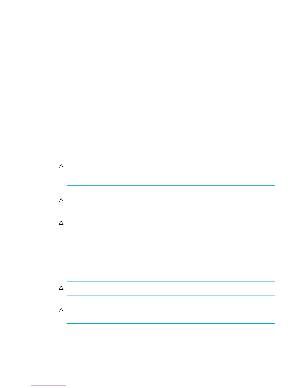
If you plan to use the mapped external LU for a Flex Copy XP pair, you must specify OPEN-V.
When the external LU to be mapped has the VMA setting, you must select OPEN-V.
Due to the advantages of the OPEN-V emulation type, HP recommends OPEN-V as the default type for
use with External Storage XP.
• Create LDEVs
Number of LDEVs that can be mapped based on the capacity supported by the emulation type
specified in the Emulation Type box. Select the number of LDEVs you want to map from the Create
LDEVs list. The default is Full. When Create LDEVs is Full, the maximum number of LDEVs that can be
created based on the capacity supported by the specified emulation type are mapped. The total
number of LDEVs being mapped appears at Total.
• IO Suppression
When you specify the OPEN-V emulation type, you can specify the mapped LU’s IO Suppression mode
(see ”External LU attributes set by mapping” on page 20).
If you suppress I/O operations from hosts (by way of the XP12000/XP10000/SVS200) to the mapped
external LU or use the mapped external LU for a Flex Copy XP pair, select Enable.
If you do not suppress I/O from hosts to the mapped external LU, select Disable (for example, for
External Storage XP).
When setting the emulation type to something other than OPEN-V, I/O Suppression mode is
automatically set to Disable.
When the external LU to be mapped has the VMA setting, IO Suppression mode is automatically set to
Disable.
CAUTION: To use the mapped external LU for products other than Flex Copy XP (such as Cache
LUN XP, Auto LUN XP, Continuous Access XP, Continuous Access XP Journal, and Business Copy
XP), set IO Suppression mode to Disable.
CAUTION: To set I/O Suppression mode to Disable, External Storage XP must be installed.
CAUTION: To set IO Suppression mode to Enable, Flex Copy XP must be installed.
• Cache Mode
Specifies if the write I/O from the host is propagated synchronously or asynchronously to the external
storage device (”External LU attributes set by mapping” on page 20).
To propagate write I/Os from the host to the external array asynchronously, select Enable.
To propagate write I/Os from the host to the external array synchronously, select Disable.
If you set IO Suppression mode to Enable, Cache Mode is automatically set to Disable.
CAUTION: If you set Disable, Cache LUN XP’s bind mode cannot be set.
CAUTION: If you set the mapped LU to a mainframe-system emulation type, the host I/O is always
propagated asynchronously to the external LU, regardless of the Cache Mode setting.
• Start CU:LDEV
First CU:LDEV number in the series of mapped destination internal LDEVs. The default is “- : -”. Interval
also appears. The default is 0.
External Storage XP user guide 79
Page 80

To have External Storage XP select the first CU:LDEV number for the mapped internal LDEV, leave the
default (“- : -”). External Storage XP searches for an available CU:LDEV number starting with 00:00,
and selects the first one it finds.
To specify the first CU:LDEV number and interval, click Select LDEV. The Select LDEV window
(Figure 48) appears.
• Alternate Path
Number of alternate paths automatically set when mapped. Values can be from 0 to 7. Default is 1.
CAUTION: If the specified number of alternate paths cannot be set, an error appears in the Preset
list.
• CLPR (see ”External LU attributes set by mapping” on page 20)
When cache memory is partitioned using XP Disk/Cache Partition, you can select the CLPR used to
access the mapped LU from the list. The SLPR number that the selected CLPR belongs to appears on the
right of the list. However, when you select a mainframe emulation type in Emulation Type, you can only
select CLPRs belonging to SLPR number 0. The Limited check box appears on the right of the SLPR
number. To display only CUs defined for the selected SLPR, select the Limited check box. To display all
CUs, regardless of the SLPR, clear the check box. By default, the Limited check box is selected.
• Select LDEV button
Displays the Select LDEV window (Figure 48) where you can select the first CU:LDEV number in the
series.
• Select Paths button
Displays the Select Paths pane (Figure 42). Use the Select Paths pane to select paths as candidates for
primary and alternate paths and select paths not set to primary and alternate paths. By default, all
paths with a confirmed connection status of normal are set as candidates for primary and alternate
paths. However, to set a specific path as the alternate path, specify candidates for alternate paths on
the Select Paths pane. Alternate paths are automatically set from the candidates, as many as the
number set in Alternate Path.
See ”Mapping external LUs individually (Add LU)” on page 71 for more information about settings on
the Select Paths pane.
CAUTION: If you do not set alternate paths on the Select Paths pane, alternate paths are
automatically set according to the WWN selected in the Device tree on the LU Operation pane
when you start the Add LU operation.
• OK button
Starts mapping internal CU:LDEV numbers to external LUs. When mapping is complete, the SSID
window appears if the SSID setting is required. If the SSID setting is not required, the Auto Map Setting
window closes, and the LU Operation pane appears.
• Cancel button
Cancels all mapping operations, closes the Auto Map Setting window, and returns to the LU Operation
pane.
80 Configuring external LUs
Page 81

Select LDEV window
Figure 48 Select LDEV window
• CU list
CU number of the local array to which you want to map the external LU.
• Interval
Interval of the CU:LDEV number for mapping each volume. When two or more LDEVs are created from
one external LU and mapped, the CU:LDEV number is set at intervals specified in each created LDEV.
For example, set the interval as follows:
•In the Device list, select three external LUs.
•In Create LDEVs on the Auto Map Setting window, select 3 (nine LDEVs are created).
•In Interval, select 1.
• Set the starting CU:LDEV number to 00:00.
For this example, LDEVs created from the first external LU are mapped to 00:00, 00:02, and 00:04,
respectively. The starting CU:LDEV number of LDEVs created from the second external LU is 00:06, and
subsequent LDEVS are mapped to 00:08 and 00:0A. The starting CU:LDEV number of LDEVs created
from the third external LU is 00:0C, and subsequent LDEVs are mapped to 00:0E and 00:10.
• LDEV map
Each cell in the map represents an internal XP CU and LDEV number. Select a cell for the internal LDEV
on the map. The selected cell turns blue, and the LU of the selected cell becomes the first CU:LDEV
number of the mapped destination LUs. Defined (in use) internal LDEVs appear in gray, and internal
LDEVs to be mapped appear in white.
• Clear button
Releases the cell selected on the LDEV map.
• OK button
Closes the Select LDEV window, and returns to the Auto Map Setting window. On the Auto Map Setting
window, the CU:LDEV number you selected on the Select LDEV window as the head CU:LDEV number
of the mapped destination internal LDEVs appears in Start CU:LDEV.
• Cancel button
Cancels all settings in the Select LDEV window, and returns to the Auto Map Setting window.
To map multiple external LUs as internal LDEVs at one time:
1. Select the LU Operation tab. The LU Operation pane appears.
2. In the Device tree, select Discovery. WWNs identifying the external array port that can be connected
appear in the tree.
External Storage XP user guide 81
Page 82

3. In the Device tree, select the port (WWN) you want to connect from the WWNs displayed. External LUs
that can be connected from the port (WWN) selected in the tree appear in the Device list.
4. In the Device list, select the external LUs you want to map as internal LDEVs, right-click, and select Add
LU (Auto). The Auto Map Setting window (Figure 47) appears.
5. Set the attributes for the external LUs you selected on the Device list.
NOTE: Attributes for all LUs mapped at one time are identical.
• To select the first CU:LDEV number of the mapped destination internal LDEVs and the mapping
interval, go to step 6.
• To let External Storage XP select the first CU:LDEV number, go to step 9.
6. Click Select LDEV. The Select LDEV window appears.
7. Select the first CU:LDEV number of the mapped destination internal LDEVs and the mapping interval.
8. Click OK. The Auto Map Setting window appears.
9. If you do not want to automatically set the primary and alternate paths, but you want to specify the
paths to be set as candidates for the primary and alternate paths, click Select Paths. The Select Paths
window appears.
To automatically set alternate paths, go to step 12.
10.Select the path and exclude it from the list of the candidates for the primary and alternate paths. For
instructions, see ”Mapping external LUs individually (Add LU)” on page 71.
11.Click OK. The Auto Map Setting window appears.
12.Click OK. The Auto Map Setting window closes, and mapping the internal CU:LDEV numbers to the
external LUs starts.
NOTE: If the CU:LDEV numbers cannot be mapped properly because too many external LUs are
selected on the Device list, all processing is canceled and the message pane appears.
• After the CU:LDEV number mapping is complete, if the SSID setting is required, the SSID window
(Figure 45) appears. Go to step 13.
• If the SSID setting is not necessary, the LU Operation pane appears. Settings appear in blue italics
in the Device tree and Device list. The contents specified in the Auto Map Setting window appear in
the Preset list. To check setting details, right-click the setting in the Preset list, and select Detail. To
cancel settings, right-click the setting in the Preset list, and select Delete. Go to step 16.
13.If you need to set an SSID to the mapped internal LDEV, the SSID window appears. When storage is
partitioned using XP Disk/Cache Partition, select the SLPR number in the SLPR list. If you select the
Limited check box and select the SLPR number, only SSIDs that can be used for the selected SLPR can
be set. If you do not select the Limited check box, you can set the SSID from all of the unused SSIDs
regardless of the selected SLPR number. Right-click the CU:LDEV number on the SSID window, and
select Set SSID. The Set SSID window (Figure 46) appears.
14.Enter the SSID on the Set SSID window. If you selected the Limited check box on the SSID window, only
SSIDs that can be used in SLPR selected on the SSID window appear in the list. If you do not select the
Limited check box on the SSID window, all of the unused SSIDs appear in the list, regardless of the
selected SLPR. You can enter 0x0004 to 0xFFFE as an SSID.
15.Click OK. The Set SSID window closes, and the LU Operation pane appears.
Settings appear in blue italics in the Device tree and Device list. Settings appear in the Preset list. To
check setting details, right-click the setting in the Preset list, and select Detail. To cancel settings,
right-click the setting in the Preset list, and select Delete.
16.Click Apply. A confirmation message appears.
If you already stopped the application, go to step 17. If you have not stopped the application, click
Cancel, stop the application, and retry the operation.
17. If you already stopped the application, click OK. A confirmation message appears.
82 Configuring external LUs
Page 83

18.Click OK. The mapping set in the Auto Map Setting window is applied to the local array, and the
specified contents appear in the Device list.
When an error occurs during the external LU mapping process, the failed setting and an error code
appears in the Preset list. To check the error message, right-click the failed setting, and select Detail.
Displaying detailed information stored in VMA (VMA information)
When VMA of LUN Security XP Extension is set for an external LU, you can check information stored in the
VMA before mapping the LU. Information stored in the VMA appears in the VMA Information pane
(Figure 49). To view the VMA Information pane, select WWN in the Device tree, and select the external
array’s port. Right-click the volume you want to display, and select VMA Information.
For more information about items displayed in the VMA Information pane, see the HP StorageWorks LUN
Security XP Extension user guide.
Figure 49 VMA Information pane
• Vendor
External array’s vendor.
• Product
External array’s product name.
• LUN
LU number of the external LU.
• Attribute
Select from the following access attributes:
• Read/Write: Read and write operations can be performed on the volume.
• Read Only: Only read operations can be performed on the volume.
• Protect: You cannot access the volume. Read and write operations cannot be performed.
• S-Vol
Indicates whether or not the volume can be specified as an S-VOL: Enable or Disable.
• Reserved
Indicates whether RAID Manager XP and Command View XP or XP Remote Web Console can be used
to make LU path and command device settings.
•Hyphen (-): You can use RAID Manager XP and Command View XP or XP Remote Web Console to
make LU path and command device settings.
• RAID Manager: You can use RAID Manager XP to make LU path and command device settings, but
cannot use Command View XP or XP Remote Web Console.
• Retention Term
Period (in days) when you cannot change the Attribute field to Read/Write.
External Storage XP user guide 83
Page 84

• Mode
Mode the RAID Manager XP user assigns to the logical volume.
• Zer: Zero Read Cap mode is assigned to the logical volume.
• Inv: Invisible mode is assigned to the logical volume.
• Zer/Inv: Zero Read Cap and Invisible mode are assigned to the logical volume.
•Hyphen (-): The RAID Manager XP user has not assigned a mode to the logical volume.
• Extent
Indicates whether extents are set.
•Asterisk (*): Extents are set.
•Hyphen (-): Extents are not set.
• Used Volumes
Licensed capacity for LUN Security XP Extension that the LU has used.
Setting alternate paths for external LUs
Before using an external LU mapped as an internal LDEV, you must set at least one alternate path from the
internal LDEV to the external LU (likely by way of an alternate controller). The number of alternate paths set
is the same as the number specified on the Add LU or Auto Map Setting window when the LU was mapped
as the internal LDEV. For more information, see ”Alternate paths” on page 22.
Use the Path Setting window (Figure 50) to add and define alternate paths to the paths set at mapping or
change the alternate paths.
NOTE: You can add or delete alternate paths by selecting multiple external LUs at one time. For more
information, see ”Adding alternate paths by selecting multiple external LUs (Add Paths)” on page 89 and
”Deleting alternate paths by selecting multiple external LUs (Delete Paths)” on page 90.
Use the Path Setting window (Figure 50) to define alternate paths.
You can perform the following operations on the Path Setting window:
• ”Defining alternate paths” on page 87
• ”Changing a defined alternate path priority” on page 87
• ”Canceling alternate path definitions” on page 88
• ”Changing alternate paths” on page 88
84 Configuring external LUs
Page 85

The Path Setting window displays information about external arrays and the condition of paths set from the
internal LDEV to the external LU.
Defined
paths
Available
paths
Figure 50 Path Setting window
• Vendor
External array’s vendor.
• Product
External array’s product name.
• Serial
External array’s serial number.
• Group
External LU group and reference number of the external LU in the group.
• Characteristic
External LU’s identification number.
• Device
External LU’s device name.
• Capacity
External LU’s capacity in blocks.
• Alternate Path List
Status of alternate paths. The Alternate Path list consists of two tables. The Configured Paths table
displays previously defined paths. The Available Paths table displays available paths. The Alternate
Path list displays the following information:
• Port: Port number in the local array connected to the external array.
• WWN: External array port’s identification number.
• LUN: LU number of the external LU.
• Priority: Priority of paths connecting to the external LU. A 1 indicates the path with the highest
priority.
• Status: Status of the path to the external LU. For information about reacting to the displayed status,
see ”Troubleshooting External Storage XP” on page 107. Possible values:
External Storage XP user guide 85
Page 86

• Normal: Path is normal.
• Unknown: Path status is unknown.
• Blockade: Path is blocked.
• External device setting changed: External array’s setting changed. For example, the path
definition was deleted or the external array itself was replaced.
• LDEV size reduced: External array’s volume capacity setting changed (volume capacity was
reduced).
• Not ready: External array replied NOTREADY.
• Illegal request: External array replied ILLEGALREQUEST.
• Command aborted: External array replied ABORTEDCOMMAND.
• Busy: External array status is BUSY.
• LDEV reserved: External array status is Reserve.
• Response error: External array status is blocked because of an abnormal reply (Response).
• Initiator port: External array’s port attribute changed to initiator port.
• RCU target port: External array’s port attribute changed to RCU target.
• Unknown port: External array’s port attribute is unknown.
• Cannot detect port: Path was removed or external array port could not be found.
• Internal error: Program error occurred, or there is a logical contradiction.
• Timeout: Processing was retried because of an abnormal reply, but a timeout occurred.
• Standby: External array’s port is standing by. Port status is normal, but cannot receive I/O.
• Target error: Port failures, such as controller blockade, were detected on the external array side.
• Checking: External Storage XP is checking defined path configuration information.
• Disconnect: Connection to the external array or LU was stopped using the Disconnect Subsystem
or Disconnect Volume command.
• Unavailable: External array replied Unavailable. The external array demands to change the
connected port. After the status becomes Unavailable, the primary path changes to the alternate
path that is in the Standby status. When the primary path changes, the path status becomes
Normal.
• Backoff: External array replied Backoff. The path status is Waiting for Recovery because a
temporary error occurred in the external array’s volume. Even if the primary path’s status
becomes Backoff, the primary path does not change to the alternate path immediately. After the
error recovery, the status becomes Normal. If you cannot recover the status from the error, the
path status changes to the other status.
• I/O TOV: Time over value for I/O to the external LU
• Qdepth: Number of Read/Write commands that can be issued (queued) to an external LU at one
time
• Path Watch: Time period beginning when the connection of all paths to the external LU is down and
ending when the external LU is blocked
• Mode: How the local array manages alternate paths when defined. Possible values:
• Single: Uses only the path with the highest priority (primary path) to execute I/Os to the external
LU. If selected, the second-highest priority alternate path is enabled only if a maintenance
operation or failure affecting the primary path occurs. That is, the external array contains
Active/Passive (for example, MSA) or Asymmetrical Active/Active controllers (for example,
Hitachi 9500V).
• Multi: Uses all of the set paths at the same time to execute I/Os to the external LU, distributing
the workload. That is, the external array contains Symmetrical Active/Active controllers (for
example, XP).
• Previous and Next buttons
If you select multiple external LUs in the Device list, click Previous to change the Alternate Path list to the
external LU appearing just above the currently displayed LU. Click Next to change the Alternate Path
list to the external LU appearing just below the currently displayed LU.
86 Configuring external LUs
Page 87

• OK button
Closes the Path Setting window, and returns to the LU Operation pane. Contents specified in the Path
Setting window appear in blue italics in the Device list, and settings appear in the Preset list.
• Cancel button
Cancels all alternate path setting operations, closes the Path Setting window, and returns to the LU
Operation pane.
Defining alternate paths
Use the Path Setting window to define alternate paths.
1. Select the LU Operation tab. The LU Operation pane appears.
2. In the Device tree, select the external LU group number. Information about the external LU mapped as
an internal LDEV appears in the Device list.
3. In the Device list, right-click the external LU, and select Path Setting. The Path Setting window appears.
The Configured Paths table displays detailed information about one currently defined path and the
alternate paths. The Available Paths table displays paths that can be set as alternate paths.
4. In the Available Paths table, right-click the row of the path to be defined as an alternate path, and
select Add.
The selected path is defined as an alternate path, and detailed information appears in the Configured
Paths table.
5. Click OK. The Path Setting window closes, and the LU Operation pane appears.
Selected rows appear in blue italics in the Device list. Specified contents also appear in the Preset list.
To check details on intended operations, right-click the setting in the Preset list, and select Detail. To
cancel settings, right-click the setting in the Preset list, and select Delete.
6. Click Apply. A confirmation message appears.
7. Click OK.
The alternate path defined in the Path Setting window is applied to the local array, and the specified
contents appear in the Device list.
If errors occur during alternate path operations, failed settings and error codes appear in the Preset list.
To check error messages, right-click the failed setting, and select Detail.
Changing a defined alternate path priority
To change the alternate path’s priority, use the Priority Up and Priority Down commands displayed in the
Path Setting window (Figure 51).
• Priority Up: Raises the priority of the path selected in the Alternate Path list.
• Priority Down: Lowers the priority of the path selected in the Alternate Path list.
As long as the external array uses Symmetrical Active/Active controllers (for example, XP), change an
alternate path to the currently used path by simply raising the priority of the alternate path or lowering the
priority of the currently used path.
NOTE: If the two paths connect to different controllers on the external array (for example, MSA), do not
use a path priority change to attempt to force a controller failover. Instead, use either a manual cable
disconnect or a Disconnect Paths GUI operation on the active controller WWN in the device list. In other
words, while the XP firmware may respond to a cable disconnect leading to the primary path and active
controller as a reason to activate the passive controller and path and continue I/Os, a simple change in
path priorities may not have the same effect, and I/Os may become blocked.
1. Select the LU Operation tab. The LU Operation pane appears.
2. In the Device tree, select the external LU group number. Information about the external LU mapped as
an internal LDEV appears in the Device list.
3. In the Device list, right-click the external LU, and select Path Setting. The Path Setting window
(Figure 50) appears.
External Storage XP user guide 87
Page 88

4. Detailed information about the currently used path and alternate path appears in the Configured Paths
table, and paths that can be defined as alternate paths appear in the Available Paths table.
5. In the Configured Paths table, right-click the row of the path defined as the alternate path, and select
Priority Up (Figure 51). The row for the selected path switches with the row above it. The alternate
path’s priority is raised, and the path is set as the currently used path.
Figure 51 Path Setting window, shortcut menu
6. Repeat the Priority Up command until the row of the selected path is displayed on the first line of the
Configured Path list and that row’s Priority column changes to 1.
When the Priority column changes to 1, the path is set as the typically used one (primary path).
7. Click OK. The Path Setting window closes, and the LU Operation pane appears.
Selected rows appear in blue italics in the Device list. Specified contents appear in the Preset list. To
check details on intended operations, right-click the setting in the Preset list, and select Detail. To cancel
settings, right-click the setting in the Preset list, and select Delete.
8. Click Apply. A confirmation message appears.
9. Click OK. The change in the alternate path defined in the Path Setting window is applied to the local
array, and specified contents appear in the Device list.
If errors occur during alternate path operations, failed settings and error codes appear in the Preset list.
To check error messages, right-click the failed setting, and select Detail.
Canceling alternate path definitions
Use the Path Setting pane to cancel an alternate path definition.
1. Follow step 1 to step 3 in ”Defining alternate paths” on page 87.
2. In the Configured Paths table, right-click the row of the alternate path, and select Delete.
The selected alternate path’s definition is canceled, and detailed information about the path is deleted
from the Configured Paths table.
3. Follow step 6 to step 8 in ”Defining alternate paths” on page 87.
Changing alternate paths
To change an alternate path, cancel the current alternate path, and then define another path as a new
alternate path.
88 Configuring external LUs
Page 89

1. Follow step 1 to step 3 in ”Defining alternate paths” on page 87.
2. In the Configured Paths table, right-click the row of the path currently defined as the alternate path,
and select Delete.
The selected alternate path’s definition is canceled, and detailed information about the path is deleted
from the Configured Paths table.
3. In the Available Paths table, right-click the row of the path to be defined as the new alternate path,
and select Add.
The specified alternate path is defined, and detailed information about the path is displayed in the
Configured Paths table.
4. Follow step 6 to step 8 in ”Defining alternate paths” on page 87.
Adding alternate paths by selecting multiple external LUs (Add Paths)
To add paths other than the alternate paths you set when you mapped the volume, add paths at one time
by selecting multiple external LUs belonging to the same external LU group. To do this, set the alternate
path in the Add Paths window (Figure 52), check the setting in the Path Setting window (Figure 50), and
apply the setting to the array.
CAUTION: After adding paths using the Add Paths window, you can change the path setting for each
external LU in the Path Setting window. However, you cannot delete all current paths to completely
interchange them with the newly added paths. At least one current path setting must remain, even if you
added new paths using the Add Paths window.
NOTE: Use the Add Paths window to add paths to multiple external LUs at one time. However, path
settings might not be applied because of the current path setting of each volume. After setting paths in the
Add Paths window, check whether or not the new path settings can be applied in the Path Setting window
for each external LU. If the setting cannot be applied, the setting from the Add Paths window does not
appear on the Path Setting window. The setting from the Add Paths window also does not appear in the
Preset list or in the LU Operation pane.
Figure 52 Add Paths window
• Port
Local array ports. After selecting a port, you can add paths.
• Selected Paths
Paths that are added as ports that configure alternate paths. WWNs identify ports on the external
array. Nothing is displayed when you initially access the Add Paths window.
• Unselected Paths
External array ports (WWNs) that can configure the path connecting with the local array port selected
in the Port list. Select WWNs from this list to add as alternate paths.
• Set
Moves WWNs selected in Unselected Paths to Selected Paths.
External Storage XP user guide 89
Page 90

• Release
Moves WWNs selected in Selected Paths to Unselected Paths.
• OK
Saves settings in the Add Paths window, closes the Add Paths window, and displays the Path Setting
window.
• Cancel
Cancels all settings in the Add Paths window, and closes the window.
To add alternate paths to multiple external LUs at one time:
1. Select the LU Operation tab. The LU Operation pane appears.
2. In the Device tree, select an external LU group number. Information about external LUs mapped as
internal LDEVs appears in the Device list.
3. In the Device list, select multiple external LUs, right-click, and select Add Paths. The Add Paths window
appears.
4. In the Port list, select the local array port. External array ports (WWNs) that can configure the path
connecting with the selected local array port appear in Unselected Paths.
5. In the Unselected Paths list, select the port’s WWNs, and click Set. The selected WWNs move to
Selected Paths.
6. Click OK. The Path Setting window appears.
7. Ensure that added paths are applied to the array in the Path Setting window. You can also change the
alternate path setting in this window. For more information, see ”Setting alternate paths for external
LUs” on page 84.
8. Click OK. The Path Setting window closes, and the LU Operation pane appears.
Selected rows in the Device list appear in blue italics. Specified settings appear in the Preset list. To
check setting details, right-click the setting in the Preset list, and select Detail. To cancel settings,
right-click the setting in the Preset list, and select Delete.
9. Click Apply. A confirmation message appears.
10.Click OK. Alternative paths added using the Add Paths and Path Setting windows are applied to the
array, and the specified content appears in the Device list.
If errors occur during alternate path definition, failed settings and error codes appear in the Preset list.
To check error messages, right-click the failed setting, and select Detail.
Deleting alternate paths by selecting multiple external LUs (Delete Paths)
You can delete paths for multiple volumes that belong to the same external LU group at one time. To delete
alternate paths for multiple external LUs at one time, select the alternate path in the Delete Paths window,
check the setting in the Path Setting window, and apply the setting to the array.
CAUTION: At least one normal path must be set on each mapped external LU.
90 Configuring external LUs
Page 91

NOTE: Use the Delete Paths window to delete paths to multiple external LUs at one time. However, the
deleted path settings might not be applied because of the current path setting of each volume. After you set
the deletion in the Delete Paths window, check whether or not the new path settings can be applied in the
Path Setting window for each external LU. If the setting cannot be applied, the setting from the Delete Paths
window does not appear on the Path Setting window. The setting from the Delete Paths window also does
not appear in the Preset list or in the LU Operation pane.
Figure 53 Delete Paths window
• Port
Local array ports. After selecting a port, you can add the paths.
• Selected Paths
Paths of WWNs to be deleted. WWNs identify ports on the external array. Nothing is displayed when
you first access the Delete Paths window.
• Unselected Paths
Ports (WWNs) on the external array that have paths configured for connecting with the local array port
selected in the Port list. Select WWNs from this list to delete paths.
• Set
Moves WWNs selected in Unselected Paths to Selected Paths.
• Release
Moves WWNs selected in Selected Paths to Unselected Paths.
• OK
Saves settings in the Delete Paths window, closes the Delete Paths window, and displays the Path
Setting window.
• Cancel
Cancels all of the settings in the Delete Paths window, and closes the window.
To delete paths for multiple volumes at one time:
1. Select the LU Operation tab. The LU Operation pane appears.
2. In the Device tree, select an external LU group number. Information about external LUs mapped as
internal LDEVs appears in the Device list.
3. In the Device list, select multiple external LUs, right-click, and select Delete Paths. The Delete Paths
window (Figure 53) appears.
4. In the Port list, select the local array port. External array ports (WWNs) that have been configured with
paths connecting to the local array port appear in the Unselected Paths list.
5. In the Unselected Paths list, select ports (WWNs of the external array), and click Set. The selected ports
move to the Selected Paths list.
6. Click OK. The Path Setting window appears.
7. Ensure that deleted paths are applied to the array in the Path Setting window. You can also change the
alternate path setting in this window. For more information, see ”Setting alternate paths for external
LUs” on page 84.
External Storage XP user guide 91
Page 92

8. Click OK. The Path Setting window closes, and the LU Operation pane appears.
Selected rows in the Device list appear in blue italics. Specified settings appear in the Preset list. To
check setting details, right-click the setting in the Preset list, and select Detail. To cancel settings,
right-click the setting in the Preset list, and select Delete.
9. Click Apply. A confirmation message appears.
10.Click OK.
Alternative paths deleted using the Delete Paths and Path Setting window are applied to the array, and
the specified content appears in the Device list.
If errors occur during alternate path definition, failed settings and error codes appear in the Preset list.
To check error messages, right-click the failed setting, and select Detail.
Checking an external LU’s status (LDEV Information)
After mapping an external LU as a local array internal LDEV, the external LU is available for operations in
External Storage XP, Flex Copy, and other HP StorageWorks products that support mapped external LUs.
Use the LDEV Information window (Figure 54) to check the status of mapped external LUs.
When a failure occurs in the path between the local array and external array, and also in the specified
alternate paths, the local array recognizes the external LU as blocked (Blockade). To restore the blocked
volume, execute the Restore command on the LDEV Information window.
Obtaining information about external LUs
The LDEV Information window displays information about external arrays and external LUs mapped as
internal LDEVs. To display this window, select the external LU group number in the Device list, right-click the
LU you want to display in the Device list, and select LDEV Information.
Figure 54 LDEV Information window
• Vendor
External array’s vendor.
• Product
External array’s product name.
• Serial
External array’s product serial number.
• Group
External LU group and reference number of the external LU in the group.
• Characteristic
92 Configuring external LUs
LDEV List
Page 93

External LU’s identification number.
• Device
External LU’s device name.
• Capacity
External LU’s capacity. When the mapped external LU’s emulation type is for open systems, capacity is
displayed in 512-byte blocks. When the mapped external LU’s emulation type is for mainframe
systems, capacity is displayed in cylinders.
NOTE: When you use the Custom Volume Size (CVS) function to make an S-VOL for a Flex Copy
XP copy pair that has the same capacity as the P-VOL, set the S-VOL’s capacity in blocks or
cylinders according to the emulation type.
• LDEV List
The status of external LU mapped as internal LDEV. The following information appears:
• CU:LDEV: CU:LDEV number of the internal LDEV to which the external LU is mapped.
• Path: Number of set paths.
• Emulation Type: External LU’s emulation type set when it was mapped.
• Capacity: External LU’s capacity.
• Status: External LU’s status. Possible values: Normal, Unknown, Blockade, Warning, and Format.
Warning indicates that some alternate paths are blocked. Format indicates the external LU is
currently being formatted.
• View all LUs
Displays information about all external LUs in the LDEV list.
• View all Volumes
When the external LU is part of a LUSE volume, displays all LDEVs that make up the LUSE volume in the
LDEV list. However, LDEVs in other external LUs are not displayed, even though those LDEVs might be
part of the LUSE volume. To check all LDEVs configuring a LUSE volume, use the Volume Detail
command (”Displaying configuration information for external LUs (Volume Detail)” on page 94).
• Previous and Next buttons
If you select multiple external LUs in the Device list in the LU Operation pane, click Previous to change
the LDEV list to the external LU appearing just above the currently displayed LU. Click Next to change
the LDEV list to the external LU appearing just below the currently displayed LU.
• OK button
Closes the LDEV Information window, and returns to the LU Operation pane. Contents specified in the
LDEV Information window appear in blue italics in the Device list, and settings appear in the Preset list.
• Cancel button
Cancels all setting operations, closes the LDEV Information window, and returns to the LU Operation
pane.
Restoring external LUs (Restore)
Use the Restore command to restore the status of external LUs.
When errors occur in all paths between the local array and external array, the local array changes the
status of the external LU to Blockade. In this case, see ”Troubleshooting External Storage XP” on page 107
and restore the path to the external array according to the troubleshooting instructions. Then execute the
Check Paths & Restore Vol. command to make the external LU in Blockade status usable. If the external LU’s
status remains Blockade, even though you restored the path to the external array and executed the Check
Paths & Restore Vol. command, execute the Restore command from the LDEV Information window.
NOTE: If paths between the local array and external array are not restored, the external LU cannot be
restored to a usable status, even though you execute the Restore command.
External Storage XP user guide 93
Page 94

NOTE: If you set a mainframe-system emulation type (such as 3390-3) when you mapped the external LU,
and you restore the mapped LU without formatting the LU or performing the Write to Control Blocks
operation, data in the volume cannot be read correctly.
1. Select the LU Operation tab. The LU Operation pane appears.
2. In the Device tree, select the external LU group number. Information about the external LU mapped as
an internal LDEV appears in the Device list.
3. In the Device list, right-click the external LU you want to restore, and select LDEV Information. The LDEV
Information window appears. The LDEV list displays information about the external LU selected in the
Device list on the LU Operation pane.
4. Select View all LUs.
5. In the LDEV list, right-click the row of the external LU to be restored, and select Restore.
Figure 55 Shortcut menu of the LDEV Information window
The Status column in the selected external LU row changes to Restore.
6. Click OK. The LDEV Information window closes, and the LU Operation pane appears.
Specified contents appear in blue italics in the Device list and appear in the Preset list. To check setting
details, right-click the setting in the Preset list, and select Detail. To cancel settings, right-click the setting
in the Preset list, and select Delete.
7. Click Apply. A confirmation message appears.
8. Click OK.
The status of the external LU set in the LDEV Information window changes to Restore (restored), and the
external LU can be used in Command View XP or XP Remote Web Console.
If errors occur when changing the external LU’s status, failed settings and error codes appear in the
Preset list. To check error messages, right-click the failed setting, and select Detail.
Displaying configuration information for external LUs (Volume Detail)
To display the Volume Detail window, right-click a row with an external LU from the LDEV list in the LDEV
Information window, and select Volume Detail (Figure 55). If you select an external LU that is a LUSE
94 Configuring external LUs
Page 95

volume in the LDEV list, the Volume Detail window displays a list of all LDEVs that make up the LUSE
volume.
Figure 56 Volume Detail window
You can also check the LDEVs making up a LUSE volume by selecting View all Volumes at the bottom of the
LDEV Information window. However, only LDEVs in the specified external LU appear. The Volume Detail
window displays all LDEVs, including LDEVs of other external LUs.
The Volume Detail command is available after you restore the external LU using the Restore command.
Disconnecting external arrays or LUs
Use the Disconnect Subsystem and Disconnect Volume commands to disconnect external LUs. This is
necessary, for example, before turning off the power on local arrays or external arrays for maintenance or
before deleting an external LU’s mapping.
The Disconnect Subsystem or Disconnect Volume command stops all host I/O to the mapped external LU,
and writes all data in the XP12000/XP10000/SVS200 cache memory to the external LU (all data is
destaged).
Mapping settings are preserved, even though the external LU is disconnected using the Disconnect
Subsystem or Disconnect Volume command. Therefore, you can resume using the external LU as a mapped
volume with the former settings. For instructions, see ”Checking the connection status and resuming
external LU operations (Check Paths & Restore Vol.)” on page 97.
CAUTION: Note the following for the Disconnect Subsystem and Disconnect Volume commands:
• After executing the Disconnect Subsystem or Disconnect Volume command, click the Refresh button ( )
on the Command View XP or XP Remote Web Console main pane to update the information, and
check the current progress status.
• If you execute the Disconnect Subsystem or Disconnect Volume command when I/Os from an
open-system host are in progress, host I/Os to the specified volume are forcibly stopped. When
executing the Disconnect Subsystem or Disconnect Volume command, stop host I/Os, and unmount the
volume from the host.
• If the volume is online from the mainframe host, you cannot execute the Disconnect Subsystem or
Disconnect Volume command. Stop host I/Os to the volume, and perform the Vary Offline operation.
• You cannot execute the Disconnect Subsystem or Disconnect Volume command for external LUs that
include LDEVs that are set as the copy pair for Flex Copy XP, Business Copy XP, ShadowImage for
z/OS, Continuous Access XP Journal, Universal Replicator for z/OS, Continuous Access XP, TrueCopy
for z/OS, or Snapshot XP. However, if the copy pair status is PSUE, you can execute these commands.
• You cannot execute the Disconnect Subsystem ore Disconnect Volume command for external LUs that
include LDEVs for which Auto LUN XP’s migration processing is in progress.
External Storage XP user guide 95
Page 96

• When executing the Disconnect Subsystem or Disconnect Volume command, the Ex-Dev. Status column
in the Device list changes to Cache Destage. Even if there is no data left in cache memory, the
displayed status remains as Cache Destage, until the Disconnect Subsystem or Disconnect Volume
command processing is complete.
• When the Disconnect Subsystem or Disconnect Volume command is executed and all data in cache
memory is written to the external LU, the Ex-Dev. Status column in the Device list changes to Disconnect.
Disconnecting all external LUs in an external array (Disconnect Subsystem)
1. In the LU Operation pane, select External Devices in the Device tree. Connected external arrays appear
in the Device list.
2. In the Device list, right-click the external array you want to disconnect from the local array, and select
Disconnect Subsystem.
Figure 57 Disconnect Subsystem and Check Paths & Restore Vol. Commands
The selected external array appears in blue italics in the LU list and Device list, and appears in the
Preset list. To check details of the intended operations, right-click the setting in the Preset list, and select
Detail. To cancel settings, right-click the setting in the Preset list, and select Delete.
3. Click Apply. A confirmation message appears.
4. Click OK.
The Ex-Dev. Status column in the Device list changes to Cache Destaging. When External Storage XP
finishes writing data from cache to the external LU, the Ex-Dev. Status column changes to Disconnect.
If errors occur during disconnect operations, failed settings and error codes appear in the Preset list. To
check error messages, right-click the failed setting, and select Detail.
CAUTION: To access the external array after executing the Disconnect Subsystem command, you must
execute the Check Paths & Restore Vol. command.
Disconnecting external LUs individually (Disconnect Volume)
1. In the LU Operation pane, select an external LU group number in the Device tree. Information about
external LUs in the selected external LU group appears in the Device list.
96 Configuring external LUs
Page 97

2. In the Device list, right-click the external LU you want to disconnect from the local array, and select
Disconnect Volume. The selected external LU group number in the Device tree and the selected external
LU in the Device list appear in blue italics. It also appears in the Preset list.
To check details of the intended operation, right-click the row in the Preset list, and select Detail. To
cancel settings, right-click the row in the Preset list, and select Delete.
3. Click Apply. A confirmation message appears.
4. Click OK. The Ex-Dev.Status column in the Device list changes to Cache Destaging. When External
Storage XP finishes writing data from cache to the external LU, the Ex-Dev. Status column changes to
Disconnect.
If errors occur during disconnect operations, failed operations and error codes appear in the Preset list.
To check error messages, right-click the failed operation row, and select Detail.
CAUTION: To access the external LU after executing the Disconnect Subsystem command, you must
execute the Check Paths & Restore Vol. command.
Checking the connection status and resuming external LU operations
(Check Paths & Restore Vol.)
When errors occur in the path between the local array and external array, and also in all alternate paths,
the local array changes the external LU’s status to Blockade. In this case, see ”Troubleshooting External
Storage XP” on page 107 and restore the path to the external array according to the troubleshooting
procedure. Execute the Check Paths & Restore Vol. command to make the external LU in Blockade status
usable.
When executing the Check Paths & Restore Vol. command for the disconnected external LU for which
mapping settings are preserved, the defined mapping setting and the external LU’s current status are
compared and checked to see if the settings match the actual status. The path status and all other mapping
configuration definitions are checked. If the external LU can be resumed as a mapped volume as a result of
the checking processing, the volume status is set to be available for I/O operations.
Use the Check Paths & Restore Vol. command to resume using an external LU that has been disconnected
using the Disconnect Subsystem or Disconnect Volume command.
CAUTION: After executing the Check Paths & Restore Vol. command, click the Refresh button ( ) on the
Command View XP or XP Remote Web Console main pane to update the information, and check the
current progress status.
NOTE: If you execute the Check Paths & Restore Vol. command and the external LU is ready to be
restored as the mapped LU, the external LU is set to accept I/Os and you can resume using the external LU
as a mapped LU. However, if the external LU is not ready to be resumed, the status of the disconnected
volume remains Blockade.
Restoring all external LUs in an external array (Check Paths & Restore Vol.)
1. In the LU Operation pane, select External Devices in the Device tree. Physically connected external
arrays appear in the Device list.
2. In the Device list, right-click the external array you want to restore the connection to the local array, and
select Check Paths & Restore Vol. The selected external array appears in blue italics in the LU list and
Device list. It also appears in the Preset list.
To check setting details, right-click the setting in the Preset list, and select Detail. To cancel settings,
right-click the setting in the Preset list, and select Delete.
3. Click Apply. A confirmation message appears.
4. Click OK.
External Storage XP user guide 97
Page 98

The path status in the Path Setting pane changes to Checking. When External Storage XP finishes
checking path status and the external array can be restored, the Status column changes to Normal. If
the external array cannot be restored, the status changes to Blockade.
Restoring external LUs individually (Check Paths & Restore Vol.)
1. In the LU Operation pane, select an external LU group number in the Device tree. Information about
external LUs in the selected external LU group appears in the Device list.
2. In the Device list, right-click the external LU you want to resume the connection to the local array, and
select Check Paths & Restore Vol.
The selected external group number in the Device tree and the selected external LU in the Device list
appear in blue italics. Rows with operations to be performed on appear in the Preset list. To check
setting details, right-click the setting in the Preset list, and select Detail. To cancel settings, right-click the
setting in the Preset list, and select Delete.
3. Click Apply. A confirmation message appears.
4. Click OK.
The path status displayed in the Path Setting pane changes to Checking. When External Storage XP
finishes checking path status and the external LU can be restored, the Status column changes to
Normal. If the external array cannot be restored, the status changes to Blockade.
Restoring external LUs (LDEV Restore)
The external LU’s status might be blocked (Blockade) if errors occur during the setting operation or the
volume-formatting process fails. In this case, see ”Troubleshooting External Storage XP” on page 107 and
restore the path to the external array according to the troubleshooting procedure. Then execute the Check
Paths & Restore Vol. command to make the external LU in Blockade status usable. If the external LU’s status
remains Blockade, even though you restored the path to the external array and executed the Check Paths &
Restore Vol. command, execute the LDEV Restore command to restore the volume.
NOTE: If the path between the local array and external array is not restored, you cannot restore the
external array’s status to be usable, even though you execute the LDEV Restore command.
NOTE: You can also restore the external LU by executing the Restore command on the LDEV Information
window. For more information, see ”Restoring external LUs (Restore)” on page 93.
Restoring volumes in an external array
1. In the LU Operation pane, select External Devices in the Device tree. Connected external arrays appear
in the Device list.
2. In the Device list, right-click the external array you want to restore all volumes in, and select LDEV
Restore.
The selected external array appears in blue italics in the Device tree and Device list. The contents of the
setting appears in the Preset list. To check setting details, right-click the setting in the Preset list, and
select Detail. To cancel the setting, right-click the setting in the Preset list, and select Delete.
3. Click Apply. A confirmation message appears.
4. Click OK.
For the external LUs of the selected external array, the Status column of the Device list changes to the
restored status, and the external LU can be used in Command View XP or XP Remote Web Console.
When errors occur during a status change for the external LU, the failed setting and error code appears
in the Preset list. To check the error message, right-click the failed setting, and select Detail.
Restoring volumes in a mapped external LU individually
1. In LU Operation pane, select an external LU group number in the Device tree. Information about the
external LUs in the selected external LU group appear in the Device list.
98 Configuring external LUs
Page 99

2. In the Device list, right-click the external LU you want to restore, and select LDEV Restore.
The selected external LU group number and external LU appear in blue italics in the Device tree and
Device list. The contents of the setting appears in the Preset list. To check setting details, right-click the
setting in the Preset list, and select Detail. To cancel the setting, right-click the setting in the Preset list,
and select Delete.
3. Click Apply. A confirmation message appears.
4. Click OK.
For the external LUs of the selected external array, the Status column of the Device list changes to the
restored status, and the external LU can be used in the Command View XP or XP Remote Web Console.
When errors occur during the status change for the external LU, the failed setting and error code
appears in the Preset list. To check the error message, right-click the failed setting, and select Detail.
Stopping the use of paths to an external LU by specifying an external
array’s WWN (Disconnect Paths)
To stop using the path between the local array and the external array by specifying the WWN that
identifies the external array’s port, select the WWN tree to display the WWN list.
NOTE: The Disconnect Paths command is not for the actual disconnection of the path to the external LU.
You must confirm that some normal paths to the external LU are set, other than the path for which you plan
to execute the Disconnect Paths command.
1. In the LU Operation pane, select the WWN tab. The WWN tree and WWN list appear.
2. In the WWN tree, select the product name of the connected external array. The WWN of all ports that
are connected to the local array and are used appear in the WWN list.
3. In the WWN list, select WWN you want to stop using. When you select the WWN identifying the
external array’s port in the list, you can stop the use of all ports of the local array connected to the port
at one time.
4. Right-click, and select Disconnect Paths. Selected items appear in blue italics in the WWN tree and
WWN list. The contents of the setting appears in the Preset list.
To check the setting details, right-click the setting in the Preset list, and select Detail. To cancel the
setting, right-click the setting in the Preset list, and select Delete.
5. Click Apply. A confirmation message appears.
6. Click OK.
Restoring paths to an external LU by specifying an external array’s
WWN (Check Paths)
To restore the path between the local array and external array by specifying the WWN that identifies the
external array’s port, select the WWN tree to display the WWN list.
NOTE: The path must be in a status that can be restored.
1. In the LU Operation pane, select the WWN tab. The WWN tree and WWN list appear.
2. In the WWN tree, select the product name of the connected external array or the WWN identifying the
external array’s port.
• If you select the product name of the connected external array, all WWNs that are connected to the
local array and are used appear in the WWN list.
• If you select the external array’s WWN, connection information about the paths between the
selected WWN and local array ports appear in the WWN list.
3. In the WWN list, select the WWN for which you want to restore the path.
External Storage XP user guide 99
Page 100

• If you selected the product name of the connected external array in the WWN tree, select the
WWN identifying the external array’s port in the WWN list. In this case, you can restore the path of
all ports of the local array connected to the WWN at one time.
• If you selected the external array’s WWN in the WWN tree, select the path between the selected
WWN and the port of the local array. In this case, you can restore the selected path to the port of
the local array individually.
4. Right click, and select Check Paths. Selected items appear in blue italics in the WWN tree and WWN
list. The contents of the setting appears in the Preset list.
To check the setting details, right-click the setting in the Preset list, and select Detail. To cancel the
setting, right-click the setting in the Preset list, and select Delete.
5. Click Apply. A confirmation message appears.
6. Click OK.
Changing an external array’s port setting
You can change the setting of an external array’s port by specifying the WWN that identifies the external
array’s port in the WWN list. Use the Change Parameter pane (Figure 58) to change the port setting.
Figure 58 Change Parameter pane
• IO TOV (10-240): Timeout value for the I/O to the external LU. The value can be 10 to 240 (in second).
• QDepth (8-128): Number of Read/Write commands that can be issued (queued) to the external LU at
one time. The value can be from 8 to 128.
• Path Blockade Watch (10-180): Time period beginning when the connection of all paths to the external
LU is down and ending when the external LU is blocked. Commands from the host are accepted until
the time set for this parameter has passed. After the time has passed, the path status becomes
Blockade. The value can be from 10 to 180 (seconds).
CAUTION: If there is no problem with the default setting, use the default setting.
CAUTION: For the external LU used for typical I/O, set IO TOV to 15 seconds.
CAUTION: To change the setting, match the value to the recommended value for the external array.
To change the setting of the port identified by the WWN by specifying an external array’s WWN:
1. In the LU Operation pane, select the WWN tab. The WWN tree and WWN list appear.
2. In the WWN tree, select the product name of the connected external array identifying the external
array’s port. The WWNs of all the ports that are connected to the local array and are used appear in
the WWN list.
3. In the WWN list, select the port for which you want to restore the path.
4. Right click, and select Change Parameter. The Change Parameter pane appears (Figure 58).
5. Change the selected port’s parameter.
100 Configuring external LUs
 Loading...