

HP StorageWorks NAS 9000s Quick Reference And Rack Installation Instructions
Quick
Reference
and Rack
Installation
Instructions
hp StorageWorks
NAS 9000s
© Copyright 2003 Hewlett-Packard Development Company, L.P.
Hewlett-Packard Company makes no warranty of any kind with regard to
this material, including, but not limited to, the implied warranties of
merchantability and fitness for a particular purpose. Hewlett-Packard shall
not be liable for errors contained herein or for incidental or consequential
damages in connection with the furnishing, performance, or use of this
material.
This document contains proprietary information, which is protected by
copyright. No part of this document may be photocopied, reproduced,
or translated into another language without the prior written consent of
Hewlett-Packard. The information contained in this document is subject to
change without notice.
Compaq Computer Corporation is a wholly-owned subsidiary of
Hewlett-Packard Company.
Hewlett-Packard Company shall not be liable for technical or editorial
errors or omissions contained herein. The information is provided “as is”
without warranty of any kind and is subject to change without notice. The
warranties for Hewlett-Packard Company products are set forth in the
express limited warranty statements for such products. Nothing herein
should be construed as constituting an additional warranty.
Printed in the U.S.A.
Thank you for purchasing your new HP
StorageWorks NAS 9000s
The NAS 9000s two-way server is housed in a modular, 4U
(7” high) rack-mount chassis that combines expandability with
efficient and space-saving design. The server combines enhanced
performance and optimal rack density with maximum availability
and manageability.
Important Safety Information
Before installing this product, read the Important Safety
Information document provided.
WARNING: This product contains energy levels that are
considered hazardous. To reduce the risk of personal injury
from electric shock and hazardous energy, individuals who
are knowledgeable of the procedures, precautions, and
hazards associated with equipment containing hazardous
energy circuits must perform the installation and servicing of
this product.
WARNING: To reduce the risk of personal injury or damage
to the equipment:
■ Observe local occupational health and safety
requirements and guidelines for manual material
handling.
■ Obtain adequate assistance to lift and stabilize the chassis
during installation or removal.
■ Be aware that the product becomes unstable when it is not
fastened to the rails.
■ Before removing the server from the rack remove all
hot-plug power supplies, power modules, and drives to
reduce the overall weight of the product.
■ Before removing the server from the rack remove all
hot-plug power supplies, power modules, and drives to
reduce the overall weight of the product.
Rack Stability
WARNING: To reduce the risk of personal injury or damage
to the equipment, be sure that:
■ The leveling jacks are fully extended to the floor.
■ The full weight of the rack rests on the leveling jacks.
■ The stabilizing feet are connected to the rack if it is a
single-rack installation.
■ The racks are coupled together in multiple-rack
installations.
■ The components are extended one at a time only. A rack
may become unstable if more than one component is
extended.
HP StorageWorks NAS 9000s
Quick Reference and Rack Installation Instructions
First Edition(September 2003)
Part Number: 352401–001
[bar code goes here in
text box, if applicable]
352401- 001
Audience Assumptions
This poster provides a quick way for customers experienced in
server installations to setup and configure the NAS 9000s server.
The following instructions are written for persons who are
qualified in installing and servicing computer equipment and are
trained in recognizing hazards in products with high-energy
levels, such as the power supplies, System Power Modules, and
redundant line cord switches in this computer system. For
detailed instructions, refer to the setup and installation guide.

1. Selecting the Optimum Environment
3. Installing Options
Select an installation site that meets the following requirements:
■ Space and airflow
■ Temperature
■ Power
■ Grounding
Detailed installation site requirements for this server are listed in
the setup and installation guide. For guidance in placing servers
and components into a rack, refer to the rack template or the
setup and installation guide.
2. Unpacking the Shipping Boxes
Unpack the server by following the instructions and illustrations
printed on the outside of the boxes. Also unpack the power cords,
rack mounting hardware, and the hardware documentation,
reference information, and software packs that are located in the
country kit box.
In addition to these items, you may need:
■ Torx T-15 tool, which is located on the rear of the server
■ Phillips screwdriver
■ Options to be installed, such as expansion boards, monitors,
power supplies, processors, processor power modules
(PPMs), and memory modules
■ Application software
■ Flat-blade screwdriver
■ Felt-tip marker or pencil
If you are installing additional options, such as expansion boards,
processors, PPMs, hard drives, or memory, you can refer to the
instructions included with the option purchase, the back of this
poster, or the setup and installation guide.
Note: For quick start memory guidelines, refer to the flowchart and
other information located on the back of this poster.
Note: Save the packing material for reuse if you need to ship the
server in the future.
Note: Protect the server from power fluctuations and temporary
interruptions with a regulating uninterruptible power supply (UPS).
This device protects the hardware from damage caused by power
surges and voltage spikes, and keeps the system in operation during a
power failure. For more information on UPS and other options, refer to
the HP website:
www.hp.com
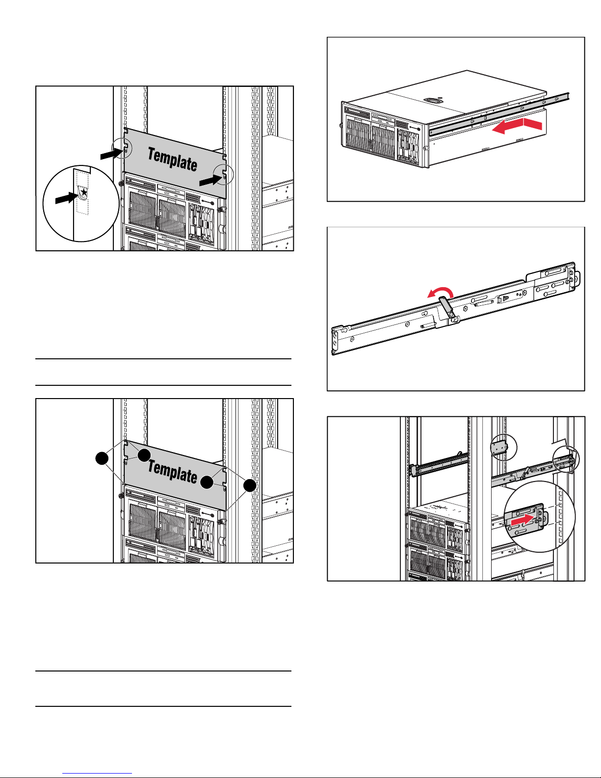
4. Installing the Server into a Rack
To identify the required space and location for the server with the
template:
1. Identify the front side of the template.
2. Starting at the bottom of the rack or at the top of a previously
mounted component, secure the template against the front of
the rack by pressing the two push tabs. Match the hole pattern
on the template with the holes in the vertical rails of the rack.
3. Align the template so that the sides of the template are even
with the sides of the rack. Tick marks on the vertical rails of
the rack help you maintain the proper alignment.
7. Install the rails on both sides of the chassis.
Note: Tick marks on the rack’s vertical posts mark off U-spaces in the
rack configuration and help to maintain the proper alignment
2
1
1
2
4. Using a pencil, mark the locations on the rack where you
insert the rack rail tabs (1).
5. On the rack, mark the top and the bottom edges of the
template (2). This step helps you align a template for the next
component.
6. Move to the rear of the rack and turn the template over so you
can use the backside of the template. Repeat steps 2 through 5
on the rear of the rack.
8. Pull the rail compression lever towards you.
9. Install the rear of the rail into the designated holes in the rear
of the rack.
Note: On the rear of the rack, make the pencil marks on the inside of
the vertical rails. These markings guide you in installing rack rails into
the interior of the rack frame.
 Loading...