

Page 1

solution integration
manual
hp StorageWorks NAS 8000
dedicated storage high availability
solution integration manual (SIM)
Product Version: 1.6.0
Edition: March 2003
Part Number: A7418-96021
Page 2

© Hewlett-Packard Company, 2003.
Hewlett-Packard Company makes no warranty of any kind with regard to this material, including, but not limited to, the implied
warranties of merchantability and fitness for a particular purpose. Hewlett-Packard shall not be liable for errors contained herein or for
incidental or consequential damages in connection with the furnishing, performance, or use of this material.
This document contains proprietary information, which is protected by copyright. No part of this document may be photocopied,
reproduced, or translated into another language without the prior written consent of Hewlett-Packard. The information contained in this
document is subject to change without notice.
Compaq Computer Corporation is a wholly-owned subsidiary of Hewlett-Packard Company.
Java® and all Java-based marks are trademarks or registered trademarks of Sun Microsystems, Inc.
Microsoft®, Windows®, and Windows NT® are trademarks of Microsoft Corporation.
UNIX® is a registered trademark of The Open Group.
All other product names mentioned herein may be trademarks of their respective companies.
Hewlett-Packard Company shall not be liable for technical or editorial errors or omissions contained herein. The information is provided
“as is” without warranty of any kind and is subject to change without notice. The warranties for Hewlett-Packard Company products are
set forth in the express limited warranty statements for such products. Nothing herein should be construed as constituting an additional
warranty.
Printed in the U.S.A.
HP StorageWorks NAS 8000 Dedicated Storage High Availability Solution Integration Manual (SIM)
Edition: March 2003
Part Number: A7418-96021
Page 3

3HP StorageWorks NAS 8000 Dedicated Storage High Availability, Solution Integration Manual (SIM)
contents
Contents
About this Guide. . . . . . . . . . . . . . . . . . . . . . . . . . . . . . . . . . . . . . . . . . . . . . . . . . . . . . . . . . . . . . . 5
Intended Audience . . . . . . . . . . . . . . . . . . . . . . . . . . . . . . . . . . . . . . . . . . . . . . . . . . . . . . . . . . . . . . . . . . . . .5
Related Documentation . . . . . . . . . . . . . . . . . . . . . . . . . . . . . . . . . . . . . . . . . . . . . . . . . . . . . . . . . . . . . . . . .5
Document Conventions . . . . . . . . . . . . . . . . . . . . . . . . . . . . . . . . . . . . . . . . . . . . . . . . . . . . . . . . . . . . . . . . .5
Getting Help. . . . . . . . . . . . . . . . . . . . . . . . . . . . . . . . . . . . . . . . . . . . . . . . . . . . . . . . . . . . . . . . . . . . . . . . . .5
HP Technical Support . . . . . . . . . . . . . . . . . . . . . . . . . . . . . . . . . . . . . . . . . . . . . . . . . . . . . . . . . . . . . . .6
HP Storage Website. . . . . . . . . . . . . . . . . . . . . . . . . . . . . . . . . . . . . . . . . . . . . . . . . . . . . . . . . . . . . . . . .6
HP Authorized Reseller. . . . . . . . . . . . . . . . . . . . . . . . . . . . . . . . . . . . . . . . . . . . . . . . . . . . . . . . . . . . . .6
1 HP StorageWorks NAS 8000 Dedicated Storage High Availability Solution Integration . . . . . . . . . . . 7
Read Me First . . . . . . . . . . . . . . . . . . . . . . . . . . . . . . . . . . . . . . . . . . . . . . . . . . . . . . . . . . . . . . . . . . . . . . . . . . . .7
Binder Contents . . . . . . . . . . . . . . . . . . . . . . . . . . . . . . . . . . . . . . . . . . . . . . . . . . . . . . . . . . . . . . . . . . . . . . . . . .8
2 Solution Integration and
Product Configuration Overview . . . . . . . . . . . . . . . . . . . . . . . . . . . . . . . . . . . . . . . . . . . . . . . . . . . 9
3 Network and Storage Planning . . . . . . . . . . . . . . . . . . . . . . . . . . . . . . . . . . . . . . . . . . . . . . . . . . . 11
Storage Overview and Terminology. . . . . . . . . . . . . . . . . . . . . . . . . . . . . . . . . . . . . . . . . . . . . . . . . . . . . . . . . .12
Physical Storage. . . . . . . . . . . . . . . . . . . . . . . . . . . . . . . . . . . . . . . . . . . . . . . . . . . . . . . . . . . . . . . . . . . . . .12
Storage Arrays. . . . . . . . . . . . . . . . . . . . . . . . . . . . . . . . . . . . . . . . . . . . . . . . . . . . . . . . . . . . . . . . . . . .12
Logical Storage . . . . . . . . . . . . . . . . . . . . . . . . . . . . . . . . . . . . . . . . . . . . . . . . . . . . . . . . . . . . . . . . . . . . . .12
Virtual Array . . . . . . . . . . . . . . . . . . . . . . . . . . . . . . . . . . . . . . . . . . . . . . . . . . . . . . . . . . . . . . . . . . . . .12
Logical Unit Number. . . . . . . . . . . . . . . . . . . . . . . . . . . . . . . . . . . . . . . . . . . . . . . . . . . . . . . . . . . . . . .12
Volume Groups . . . . . . . . . . . . . . . . . . . . . . . . . . . . . . . . . . . . . . . . . . . . . . . . . . . . . . . . . . . . . . . . . . .12
File Volumes . . . . . . . . . . . . . . . . . . . . . . . . . . . . . . . . . . . . . . . . . . . . . . . . . . . . . . . . . . . . . . . . . . . . .13
Directories . . . . . . . . . . . . . . . . . . . . . . . . . . . . . . . . . . . . . . . . . . . . . . . . . . . . . . . . . . . . . . . . . . . . . .13
Snapshots. . . . . . . . . . . . . . . . . . . . . . . . . . . . . . . . . . . . . . . . . . . . . . . . . . . . . . . . . . . . . . . . . . . . . . . .13
High Availability . . . . . . . . . . . . . . . . . . . . . . . . . . . . . . . . . . . . . . . . . . . . . . . . . . . . . . . . . . . . . . . . . . . . .14
Clusters . . . . . . . . . . . . . . . . . . . . . . . . . . . . . . . . . . . . . . . . . . . . . . . . . . . . . . . . . . . . . . . . . . . . . . . . .14
Failover Packages . . . . . . . . . . . . . . . . . . . . . . . . . . . . . . . . . . . . . . . . . . . . . . . . . . . . . . . . . . . . . . . . .14
Data Protection. . . . . . . . . . . . . . . . . . . . . . . . . . . . . . . . . . . . . . . . . . . . . . . . . . . . . . . . . . . . . . . . . . . . . . .15
RAID Levels . . . . . . . . . . . . . . . . . . . . . . . . . . . . . . . . . . . . . . . . . . . . . . . . . . . . . . . . . . . . . . . . . . . . .15
Active Spare . . . . . . . . . . . . . . . . . . . . . . . . . . . . . . . . . . . . . . . . . . . . . . . . . . . . . . . . . . . . . . . . . . . . .15
HA Storage Configuration . . . . . . . . . . . . . . . . . . . . . . . . . . . . . . . . . . . . . . . . . . . . . . . . . . . . . . . . . . . . . . . . .16
Port Designation and Enumeration . . . . . . . . . . . . . . . . . . . . . . . . . . . . . . . . . . . . . . . . . . . . . . . . . . . . . . .18
Integrated Lights-Out (iLO) . . . . . . . . . . . . . . . . . . . . . . . . . . . . . . . . . . . . . . . . . . . . . . . . . . . . . . . . .18
NIC Ports. . . . . . . . . . . . . . . . . . . . . . . . . . . . . . . . . . . . . . . . . . . . . . . . . . . . . . . . . . . . . . . . . . . . . . . .18
Page 4

Contents
4 HP StorageWorks NAS 8000 Dedicated Storage High Availability, Solution Integration Manual (SIM)
Planning Worksheets . . . . . . . . . . . . . . . . . . . . . . . . . . . . . . . . . . . . . . . . . . . . . . . . . . . . . . . . . . . . . . . . . . . . .21
Available Disk Space Spreadsheets. . . . . . . . . . . . . . . . . . . . . . . . . . . . . . . . . . . . . . . . . . . . . . . . . . . . . . .21
Storage Planning Worksheet . . . . . . . . . . . . . . . . . . . . . . . . . . . . . . . . . . . . . . . . . . . . . . . . . . . . . . . . . . . .24
HA Planning Worksheet . . . . . . . . . . . . . . . . . . . . . . . . . . . . . . . . . . . . . . . . . . . . . . . . . . . . . . . . . . . . . . .26
Network Planning Worksheet Node 1. . . . . . . . . . . . . . . . . . . . . . . . . . . . . . . . . . . . . . . . . . . . . . . . . .28
Network Planning Worksheet Node 2. . . . . . . . . . . . . . . . . . . . . . . . . . . . . . . . . . . . . . . . . . . . . . . . . .31
4 Installation Guide . . . . . . . . . . . . . . . . . . . . . . . . . . . . . . . . . . . . . . . . . . . . . . . . . . . . . . . . . . . . . 35
1. Review the Planning Worksheets. . . . . . . . . . . . . . . . . . . . . . . . . . . . . . . . . . . . . . . . . . . . . . . . . . . . . . . . . .36
2. Check the Contents of Each Package . . . . . . . . . . . . . . . . . . . . . . . . . . . . . . . . . . . . . . . . . . . . . . . . . . . . . . .37
System Components. . . . . . . . . . . . . . . . . . . . . . . . . . . . . . . . . . . . . . . . . . . . . . . . . . . . . . . . . . . . . . . . . . .37
Shipping Configurations . . . . . . . . . . . . . . . . . . . . . . . . . . . . . . . . . . . . . . . . . . . . . . . . . . . . . . . . . . . . . . .39
3. Rack the Components. . . . . . . . . . . . . . . . . . . . . . . . . . . . . . . . . . . . . . . . . . . . . . . . . . . . . . . . . . . . . . . . . . .41
Safety Tips . . . . . . . . . . . . . . . . . . . . . . . . . . . . . . . . . . . . . . . . . . . . . . . . . . . . . . . . . . . . . . . . . . . . . . . . . .41
4. Connect the Components . . . . . . . . . . . . . . . . . . . . . . . . . . . . . . . . . . . . . . . . . . . . . . . . . . . . . . . . . . . . . . . .43
Connect the Array(s) . . . . . . . . . . . . . . . . . . . . . . . . . . . . . . . . . . . . . . . . . . . . . . . . . . . . . . . . . . . . . . . . . .44
Connecting VA7100 Arrays. . . . . . . . . . . . . . . . . . . . . . . . . . . . . . . . . . . . . . . . . . . . . . . . . . . . . . . . . . . . .45
Connecting VA74xx Series Arrays . . . . . . . . . . . . . . . . . . . . . . . . . . . . . . . . . . . . . . . . . . . . . . . . . . . . . . .46
Connect a Tape Library (optional). . . . . . . . . . . . . . . . . . . . . . . . . . . . . . . . . . . . . . . . . . . . . . . . . . . . . . . .47
Connect the Network Ports . . . . . . . . . . . . . . . . . . . . . . . . . . . . . . . . . . . . . . . . . . . . . . . . . . . . . . . . . . . . .47
Bonding the Network Ports . . . . . . . . . . . . . . . . . . . . . . . . . . . . . . . . . . . . . . . . . . . . . . . . . . . . . . . . . . . . .48
Connect Power. . . . . . . . . . . . . . . . . . . . . . . . . . . . . . . . . . . . . . . . . . . . . . . . . . . . . . . . . . . . . . . . . . . . . . .48
5. Define Basic Network and HA Settings. . . . . . . . . . . . . . . . . . . . . . . . . . . . . . . . . . . . . . . . . . . . . . . . . . . . .50
Configure the Quorum server. . . . . . . . . . . . . . . . . . . . . . . . . . . . . . . . . . . . . . . . . . . . . . . . . . . . . . . . . . . .50
Configure the NAS servers . . . . . . . . . . . . . . . . . . . . . . . . . . . . . . . . . . . . . . . . . . . . . . . . . . . . . . . . . . . . .50
6. Run the Command View NAS Configuration Wizard. . . . . . . . . . . . . . . . . . . . . . . . . . . . . . . . . . . . . . . . . .52
7. Build the Storage System . . . . . . . . . . . . . . . . . . . . . . . . . . . . . . . . . . . . . . . . . . . . . . . . . . . . . . . . . . . . . . . .54
Create LUNs. . . . . . . . . . . . . . . . . . . . . . . . . . . . . . . . . . . . . . . . . . . . . . . . . . . . . . . . . . . . . . . . . . . . . . . . .54
Create Volume Groups. . . . . . . . . . . . . . . . . . . . . . . . . . . . . . . . . . . . . . . . . . . . . . . . . . . . . . . . . . . . . . . . .54
Create and Start Failover Packages . . . . . . . . . . . . . . . . . . . . . . . . . . . . . . . . . . . . . . . . . . . . . . . . . . . . . . .55
Create File Volumes. . . . . . . . . . . . . . . . . . . . . . . . . . . . . . . . . . . . . . . . . . . . . . . . . . . . . . . . . . . . . . . . . . .55
Assign Shared Access . . . . . . . . . . . . . . . . . . . . . . . . . . . . . . . . . . . . . . . . . . . . . . . . . . . . . . . . . . . . . . . . .56
8. Enable the Software Modules. . . . . . . . . . . . . . . . . . . . . . . . . . . . . . . . . . . . . . . . . . . . . . . . . . . . . . . . . . . . .58
Next Steps. . . . . . . . . . . . . . . . . . . . . . . . . . . . . . . . . . . . . . . . . . . . . . . . . . . . . . . . . . . . . . . . . . . . . . . . . . . . . .59
Installing Additional Software. . . . . . . . . . . . . . . . . . . . . . . . . . . . . . . . . . . . . . . . . . . . . . . . . . . . . . . . . . .59
Using the System . . . . . . . . . . . . . . . . . . . . . . . . . . . . . . . . . . . . . . . . . . . . . . . . . . . . . . . . . . . . . . . . . . . . .59
Where to Go for Help. . . . . . . . . . . . . . . . . . . . . . . . . . . . . . . . . . . . . . . . . . . . . . . . . . . . . . . . . . . . . . . . . .59
5 Safety and Regulatory Information . . . . . . . . . . . . . . . . . . . . . . . . . . . . . . . . . . . . . . . . . . . . . . . . 61
Index . . . . . . . . . . . . . . . . . . . . . . . . . . . . . . . . . . . . . . . . . . . . . . . . . . . . . . . . . . . . . . . . . . . . . . 63
Page 5
5HP StorageWorks NAS 8000 Dedicated Storage High Availability, Solution Integration Manual (SIM)
about this guide
About this Guide
About this Guide
This installation guide provides information to help you:
■ install your customer’s HP StorageWorks NA S 8000 system.
■ configure your customer’s HP StorageWorks NAS 8000 system.
Intended Audience
This guide is intended for use by system administrators, technicians, and HP on-site service
representatives, who are experienced with HP StorageWorks NAS 8000 systems.
Related Documentation
In addition to this guide, HP provides HP StorageWorks NAS 8000 1.6.0 Release Notes.
Document Conventions
The document conventions included in Table 1 apply in most cases.
Getting Help
If you still have a question after reading this guide, contact an HP authorized service provider
or access our website:
www.hp.com/support/nas8000
.
Table 1: Document Conventions
Element Convention
Cross-reference links Blue text: Figure 1
Key and field names, menu items,
buttons, and dialog box titles
Bold
File names, application names, and text
emphasis
Italics
User input, command and directory
names, and system responses (output
and messages)
Monospace font
COMMAND NAMES are uppercase
monospace font unless they are case
sensitive
Variables <monospace, italic font>
Website addresses Blue, underlined sans serif font text:
http://www.hp.com
Page 6

About this Guide
6 HP StorageWorks NAS 8000 Dedicated Storage High Availability, Solution Integration Manual (SIM)
HP Technical Support
In North America, call technical support at 1-800-652-6672, available 24 hours a day, 7 days a
week.
Note: For continuous quality improvement, calls may be recorded or monitored.
Outside North America, call technical support at the nearest location. Telephone numbers for
worldwide technical support are listed on the HP website under support:
http://thenew.hp.com/country/us/eng/support.html
.
Be sure to have the following information available before calling:
■ Technical support registration number (if applicable)
■ Product serial numbers (NAS 8000 and arrays in question)
■ Product model names and numbers
■ Applicable error messages
■ Operating system type and revision level (from Command View NAS Identity page)
■ Detailed, specific questions
HP Storage Website
The HP website has the latest information on this product, as well as the latest drivers. Access
storage at:
http://thenew.hp.com/country/us/eng/prodserv/
storage.html
. From this website, select the appropriate product or solution.
HP Authorized Reseller
For the name of your nearest HP authorized reseller:
■ In the United States, call 1-800-345-1518
■ In Canada, call 1-800-263-5868
■ Elsewhere, see the HP website for locations and telephone numbers:
http://www.hp.com
.
Page 7

7HP StorageWorks NAS 8000 Dedicated Storage High Availability, Solution Integration Manual (SIM)
1
HP StorageWorks NAS 8000
Dedicated Storage
High Availability Solution Integration
Read Me First
This binder includes the details of the integration tasks that Hewlett-Packard or an authorized
reseller has performed:
■ The first section, Solution Integration and Product Configuration Overview, gives you a
detailed picture of the solution you ordered from Hewlett Packard. Depending on the
system you ordered, and through whom it was purchased, you will either receive
system-specific configuration information or sample configuration information.
■ The remaining sections of this binder will be used by you or your installation specialist,
who will work with you to plan and install your HP Network Attached Storage (NAS)
8000 system according to your specific requirements.
Before installing the HP StorageWorks NAS 8000 solution, you must first complete the items
in the Network and Storage Planning section of this binder. If your installation specialist has
not done so already, he or she will contact you to schedule a joint planning session.
After the planning is complete, your installation specialist will perform tasks specified in this
binder’s “Installation Guide” section.
We sincerely hope that you will be delighted with our integration services, and we are looking
forward to hearing from you.
Page 8

HP StorageWorks NAS 8000 Dedicated Storage High Availability Solution Integration
8 HP StorageWorks NAS 8000 Dedicated Storage High Availability, Solution Integration Manual (SIM)
Binder Contents
This binder contains the following sections:
Section Audience Purpose
1. HP StorageWorks NAS 8000
Dedicated Storage High
Availability Solution
Integration
Customer IT administrator Introduction
2. Solution Integration and
Product Configuration
Overview
Customer IT administrator Product information
3. Network and Storage Planning Installation specialist and customer
IT administrator
Pre-installation planning session
4. Installation Guide Installation specialist Hardware installation and software
configuration
5. Safety Installation specialist and customer
IT administrator
Warnings and regulatory information
Page 9
9HP StorageWorks NAS 8000 Dedicated Storage High Availability, Solution Integration Manual (SIM)
2
Solution Integration and
Product Configuration Overview
This section contains the following documents, which are either sample documents (labeled as
such), or were customized for your system and inserted by the Integration Center:
■ Deployment information
■ Rack, server and component configurations
■ Parts list
■ Network, cabling, and power connection diagrams
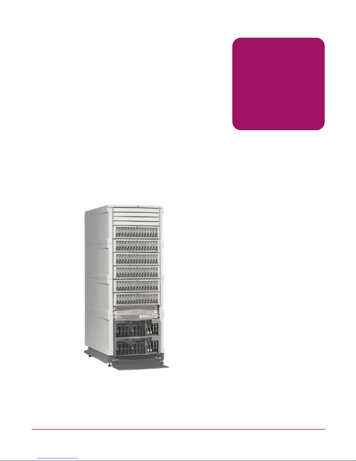
Figure 1: HP StorageWorks NAS 8000 Racked System
Sample high availability solution shown here.
Page 10
Solution Integration and Product Configuration Overview
10 HP StorageWorks NAS 8000 Dedicated Storage High Availability, Solution Integration Manual (SIM)
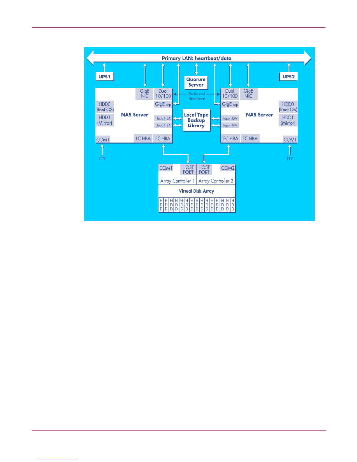
Figure 2: Sample Configuration—NAS 8000 dedicated storage HA
For information on NIC ports, see NIC Ports on page 18 of this manual.
Page 11

11HP StorageWorks NAS 8000 Dedicated Storage High Availability, Solution Integration Manual (SIM)
3
Network and Storage Planning
This section contains pre-planning materials that the installation specialist can re view with the
customer before the HP StorageWorks NAS 8000 system arrives onsite.It includes:
■ System Overview, a conceptual overview of the storage system of the HP StorageWorks
NAS 8000 solution, including:
— Storage Overview and Terminology
— HA Storage Configuration
■ Planning Worksheets, where you can record network and storage settings for the NAS
8000 system. The information in the planning worksheets is required to install and
configure the system.
— Determining Available Disk Space
— Storage Planning
— High Availability Planning
—Network Planning
You need to construct an overall storage architecture by:
1. Determining the amou nt of total storage available.
2. Deciding how to allocate it to different groups or functions.
Storage space is spread across volume groups. In these volume groups, file volumes di vide the
disk space. It is important to plan storage space prior to creating file volumes. Although the
NAS 8000 lets you expand volume groups later, you may want to reserve extra space during
setup to allow for the use of the backup process via snapshots (integrated into the user
interface). For more information, see Snapshots on page 13.
Page 12

Network and Storage Planning
12 HP StorageWorks NAS 8000 Dedicated Storage High Availability, Solution Integration Manual (SIM)
Storage Overview and Terminology
The NAS 8000 is an easy-to-manage storage solution for heterogeneous environments
including Windows, UNIX, and Linux.
The storage space on the NAS 8000 is made up of physical and logical storage:
■ Physical storage refers to the hardware you use for data storage.
■ Logical storage is created by software that organizes your physical storage into file
volumes and directories that are made accessible to users.
In addition, the HA configurations include high-availability features such as redundant
hardware and failover packages.
The installation specialist works with the customer to construct an overall storage architecture,
determining the total amount of storage available and how it should be allocated to different
groups or functions. Data protection, including two RAID levels and active spare settings,
should also be considered.
Physical Storage
Storage Arrays
The NAS 8000 Dedicated Storage HA solution uses either the HP Virtual Array 7100, or the
HP Virtual Array 74xx series high-performance, high-availability, multi-terabyte storage
arrays. One- and two-array configurations are supported.
Logical Storage
Virtual Array
The term “Virtual Array” refers to the way the disks within the array are treated as a pool of
data storage blocks instead of real physical disks.
Because data is spread across all of the disks in the array, logical-to-physical data maps keep
track of where the data is physically located on the disks in the array . These maps are stored in
array controller cache memory. The host has no visibility of the cache data maps; it is simply
presented with logical units (LUNs) for data storage operations.
Logical Unit Number
A logical unit number (LUN) is a logical aggregation of space on physical drives. LUNs are
unique identifiers that enable the controller to differentiate between separate devices (each of
which is a logical unit). Each LUN is a unique number that identifies a specific unit of storage.
The NAS 8000 supports up to 128 LUNs in single-array dedicated-storage configurations and
as little as 31 LUNs in FC-attach multiple-array configurations.
Volume Groups
A volume group is the aggregation of one or more LUNs. Volume groups combine the space
from LUNs and make the space accessible to the file system for creating file volumes and
directories, which can then be made accessible to users.
Page 13

Network and Storage Planning
13HP StorageWorks NAS 8000 Dedicated Storage High Availability, Solution Integration Manual (SIM)
File Volumes
A volume group is divided into one or more file volumes. File volumes are the basic unit of
logical storage for a file system on the NA S 8000 . File v olumes can be further subdivided into
individual directories.
Directories
Directories let you organize information. Directories contain files or other persistent data
structures in a file system that contains information about other files. Directories are usually
organized hierarchically and may contain both files and other directories, and are used to
organize collections of files for applications or convenience.
Snapshots
A snapshot is a read-only virtual copy of a f ile v ol ume at a specif ic point in time. As such, it is
an important part of an overall data-protection plan. Snapshots provide nearly instantaneous
access to previous versions of a file stored on the NAS 8000 solution.
When you create a snapshot of a file volume, it initially consumes no physical space. Howe ver ,
as users modify the file volume, the snapshot tracks all changes between the original file
volume and the modified file volume. If an error occurs and a user needs to revert to the
previous version, the snapshot version of the file can be restored.
When you create a snapshot, you must allocate storage space in the volume group in which to
save the snapshot file v olume. The recommended initial allocation is 10% of the size of the f ile
volume on which you are using snapshot.
Keep in mind the following when managing your allocated space:
■ You can increase the amount of space allocated to the snapshot, as long as there is space
available on the volume group.
■ If the allocated space fills during a snapshot’ s e xistence, you can no longer view or extend
the allocated space. An incomplete snapshot has been captured, and therefore, should be
deleted. The snapshot will be deleted automatically only upon reboot or package failover.
■ Consider how dynamic your data will be. For file volumes in which data changes rapidly,
snapshots will consume a larger amount of space. At the extreme limit, a file volume can
change so much from the original state that the snapshot consumes the same amount of
space as the original file volume. Typically, data does not change that rapidly, and the
usage and growth of snapshot space is relatively slow.
■ You may also use the autogrow feature, which allows you to allocate a small amount of
space initially, then instruct the system to increase the size of the allocated space on an
as-needed basis. Ensure that the autogrow threshold is set low enough that it can keep up
with the rate of change in the snapshot files. If the data change rate is greater than the rate
at which the autogrow feature is responding, the allocated space can fill up, thereby
capturing an incomplete snapshot as described above.
Note: If you take a snapshot of an empty file volume, every file added to that volume will be
duplicated in the snapshot. This will require you to allocate a much larger storage space than you
would otherwise need.
Snapshots are optional and may be created at any time after a file volume is created. Users can
add or extend snapshots at a later time if there is enough free space available in the volume
group.
Page 14

Network and Storage Planning
14 HP StorageWorks NAS 8000 Dedicated Storage High Availability, Solution Integration Manual (SIM)
High Availability
The NAS 8000 dedicated storage high av ailabi lity solution includes a cluster, or group, of two
NAS servers that function as a unified system. It also includes a Quorum server.
The main purpose of high-availability clusters is to provide a higher degree of storage
availability to client systems than is possible with a single server. This is accomplished by
eliminating single points of failure and providing functional redundancy. Uninterrupted
service is provided by failing o ver file serving capabilities (see Failover Packages on page 14)
to a secondary server in the event of a failure in the primary server in the cluster.
■ The NAS server s provide failover services for each other.
■ The Quorum server manages the NAS servers, or cluster nodes, and provides cluster
arbitration services that prevent data corruption.
Clusters
HA clusters provide a higher degree of storage availability than is possible with a single serv er .
This is provided by:
■ Hardware component redundancy designed to eliminate single points of failure. Each
cluster consists of two NAS servers (nodes) plus one Quorum server. The Quorum server
can be shared by multiple NAS Clusters.
■ All storage is grouped into separate units that are given names and are accessible only by
an assigned, unique virtual IP address. These separate units of storage are referred to as
failover packages. Storage is assigned to a failover package in units of volume groups. A
failover package may have one or more vo lume groups assigned to it.
Note: HP currently supports a two-node cluster for the HP NAS 8000 solution.
See the HP support web site at http://hp.com/support/nas8000 for a technical paper called
Configuring and Using an HP NAS 8000 HA Cluster for more information.
Failover Packages
When a package failure is detected, the failover package is halted and fails over to another
node, provided that an eligible adoptive node is present. Each failover package and its
associated resources are monitored independently. This allows failures that are limited to a
single failover package to be handled without affecting the state of other failover packages.
The NAS solution supports two failover models:
■ Active/Active (or “Dual Active”) means that both cluster nodes can be serving data
simultaneously. The nodes provide failover services for each other, but can be fully
utilized at all times. This mode is achieved b y configuring failo v er packages to run on both
cluster nodes – effectively dividing the storage between the nodes.
■ Active/Passive (or “Single Active”) means that one node is actively serving data while the
other node is in full-time stand-by mode, becoming active only when the other node fails.
This mode can be realized by configuring all of the failo ver packages and storage to run on
only one node. Without any failover packages to run, the other node waits and monitors
the other node for failure.
Page 15

Network and Storage Planning
15HP StorageWorks NAS 8000 Dedicated Storage High Availability, Solution Integration Manual (SIM)
Data Protection
RAID Levels
Redundant Array of Inexpensive Disks (RAID) technology uses different industry-standard
techniques for storing data and maintaining data redundancy. These techniques, called “RAID
levels,” define the method used for distributing data on the disks in a logical unit (LUN). The
storage arrays used in the NAS 8000 solution support the following RAID levels:
■ RAID 1+0. RAID 1+0 provides data redundancy and good perform ance. However, the
performance is achieved by using a less efficient technique of storing redu ndant data
called “mirroring.” Mirroring maintains two sets of the data: a primary set and a backup
set, or “mirror,” of the primary set. Therefore, half of the disk space is consumed by
redundant data.
■ AutoRAID. AutoRAID is a combination of RAID 1+0 and 5DP (RAID 5 Double Parity).
RAID 5DP provides data redundancy and improves cost-efficiency by using a more
efficient method of storing redundant data. However, there is a performance penalty for
each write operation.
AutoRAID relieves you of many of the decisions regarding RAID levels and data location
by automatically selecting RAID 1+0 or RAID 5DP depending on the usage patterns of
the data. AutoRAID automatically manages your data for you, providing redundancy and
high performance with minimal involvement. This configuration eliminates the
requirement for the system administrator to understand and configure RAID levels.
Note: The information for AutoRAID presented here applies to VA arrays only.
For additional information on RAID settings, see your storage array user’s guide or search for
RAID levels at
http://www.hp.com
.
Active Spare
The active spare feature in the storage array of fers increased protection against disk f ailure. An
active spare ensures that the array can restore data redundancy and performance as quickly as
possible following a hard disk failure.
An active spare reserves capacity to perform a rebuild in the event of a disk failure. If you are
using disks of different capacities in your array, active spare reserves enough space to rebuild
the largest disk. As with logical volumes, the capacity reserved for the active spare is
distributed across all the disks in the array; no one physical disk contains the active spare.
Active spare is similar to the dedicated hot spare disks used in some conventional arrays.
Howev er, those arrays let the hot spare remain idle until it is needed. This array uses the active
spare for RAID 1+0 storage until the spare is needed. This provides the added benefit of
enhancing performance while also protecting against disk failure.
Page 16

Network and Storage Planning
16 HP StorageWorks NAS 8000 Dedicated Storage High Availability, Solution Integration Manual (SIM)
HA Storage Configuration
This section provides suggestions for configuring the storage on an NAS 8000 with
high availability (HA) features. For a description of HA, see Physical Storage on page 12.
On a simple dedicated-storage NAS system without HA features, the simplest way to
configure the storage is to create a single LUN for the entire array, then create one volume
group with multiple file volumes beneath it. Ho we v er, in an HA cluster with two NAS servers,
each volume group can be active on only one NAS server, or node, at a time. Therefore, if you
are using active/active failover packages (see Failover Packages on page 14), you must create
at least two volume groups so each node can access some of your storage.
When determining how many LUNs and volume groups to create, consider the following:
■ A volume group can be active on only one node at a time.
■ A volume group can be assigned to only one failover package.
■ File volumes can’t be split between failover packages or nodes.
■ Multiple volume groups can be assigned to the same failover package.
■ A failover package can only run on one node at a time.
■ The HA cluster is limited to 60 failover packages total (both nodes combined).
■ A package is the smallest unit of failover.
■ A volume group is the smallest unit of storage that can be failed over.
■ If a failover package contains multiple volume groups and a single volume group, file
volume or even share fails, the entire package will be failed over.
■ More failover packages means a higher degree of granularity to balance the failover
packages between the nodes and detect failures.
■ More failover packages also results in higher complexity in the cluster configuration and
requires more virtual IP addresses to keep track of.
■ The failover packages should be divided between the cluster nodes such that the storage
access load (from client systems) will be balanced. This may or may not correspond to
balanced storage capacity between the nodes.
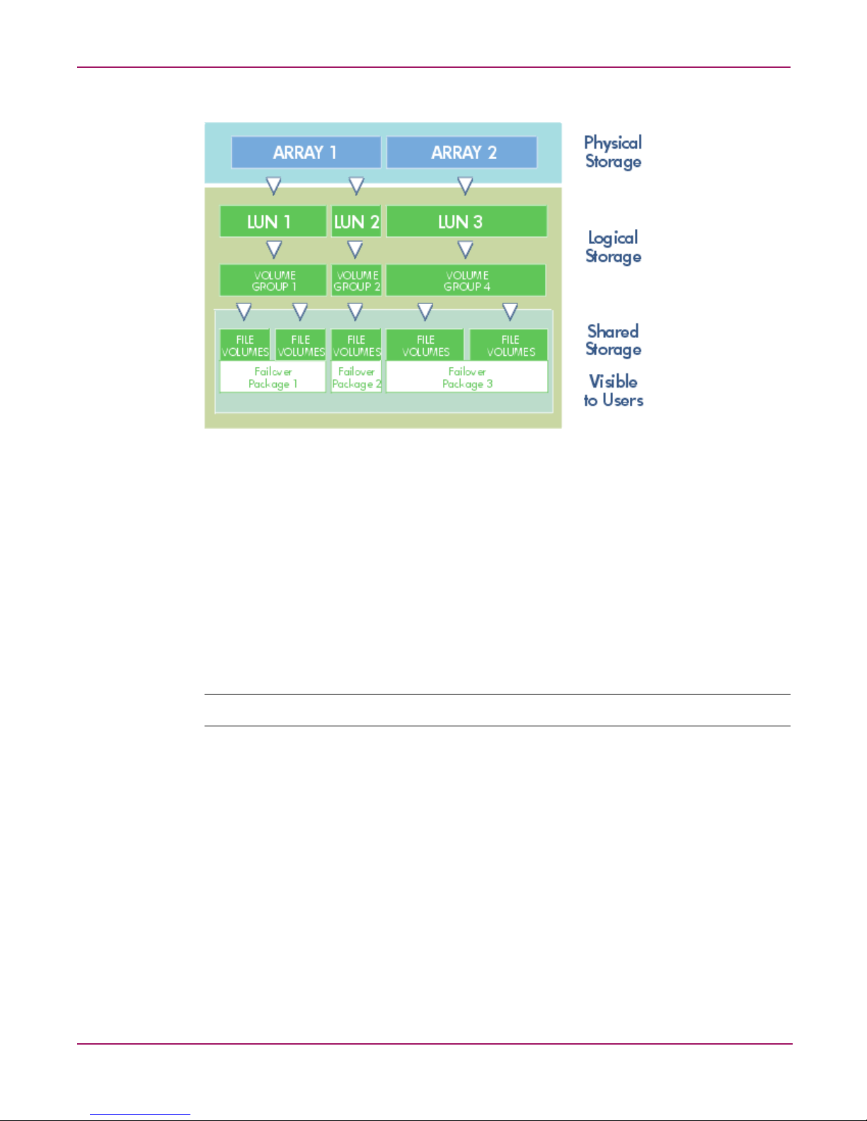
The illustrations on the following pages depict common storage configurations:
■ Single array with one LUN and one volume group (for active/passive
failoverconfigurations).
■ Single array with multiple LUNs, volume groups and failover packages.
■ Multiple arrays, LUNs, volume groups and failover packages.
Page 17
Network and Storage Planning
17HP StorageWorks NAS 8000 Dedicated Storage High Availability, Solution Integration Manual (SIM)
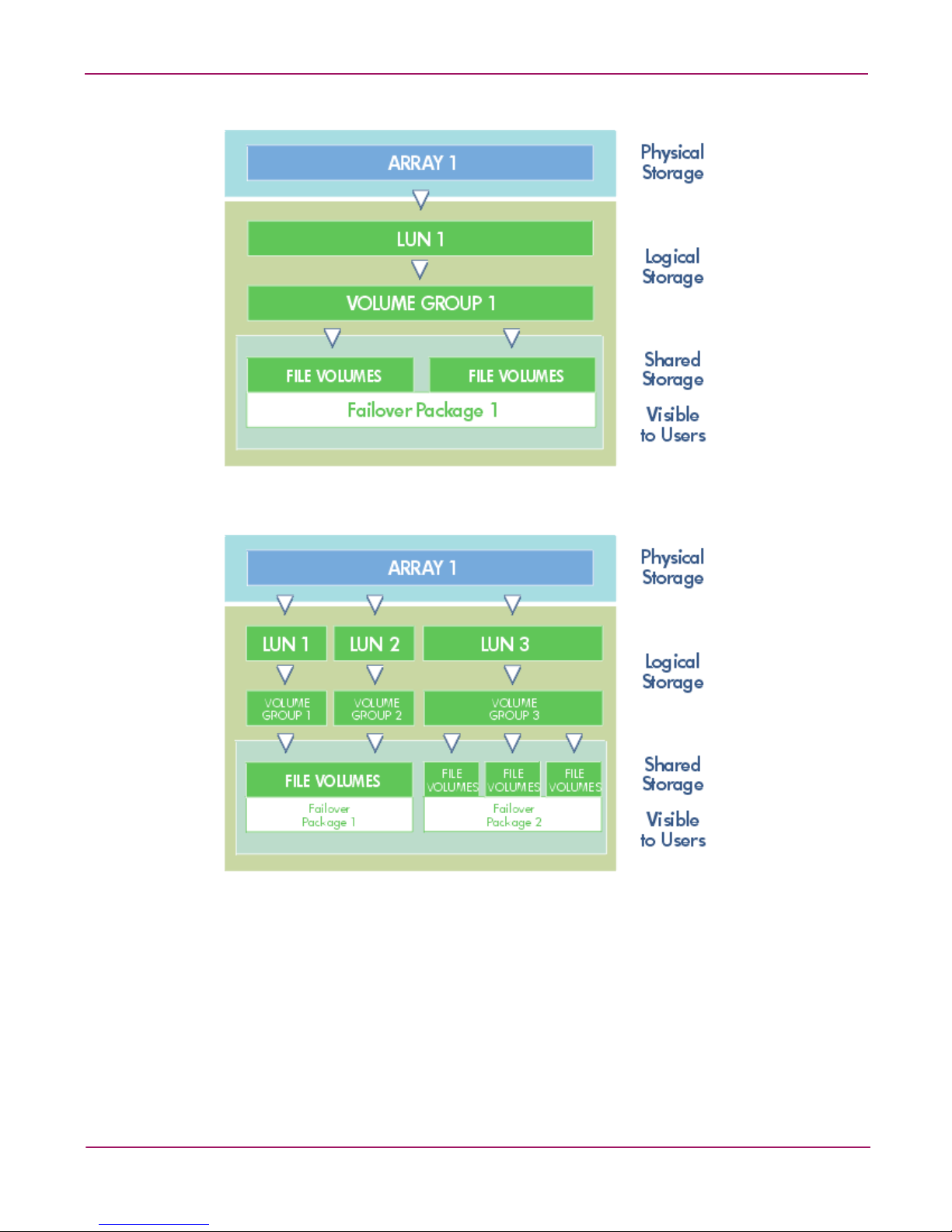
Figure 3: Single Array with One LUN and One Volume Group for Active/Passive Failover
Figure 4: Single array with Multiple LUNs, Volume Groups and Failover Packages
Page 18
Network and Storage Planning
18 HP StorageWorks NAS 8000 Dedicated Storage High Availability, Solution Integration Manual (SIM)
Figure 5: Multiple Arrays, LUNs, Volume Groups and Failover Packages
Port Designation and Enumeration
Integrated Lights-Out (iLO)
The server's on-board NIC is dedicated to the Integrated Lights Out (iLO) controller. The iLO
is a management chip embedded in the NAS 8000 server. The iLO features are accessed from
a network client using a web browser. This allows an administrator to fully control the host
server's display (with keyboard and mouse control) from a remote location, regardless of the
state of the host server or the host server's operating system. Consequently, you can install,
configure, monitor, update, and troubleshoot your NAS 8000 from a desktop located
anywhere.
Note: A separate network data line and IP address are required to use the iLO.
NIC Ports
There is a method to NIC port enumeration on the NAS 8000. Understanding these allows the
correlation of NIC ports logical names (i.e. ‘ethX’) to physical port locations.
Supported NICs are as follows:
■ NC3134 (138603-B21) Expandable dual-port 10/100 - included in all configurations
■ NC3135 (138604-B21) Dual-port 10/100 upgrade for NC3134
■ NC7770 (244948-B21) Single-port PCI-X gigabit copper
■ NC7132 (153543-B21) Single-port gigabit copper upgrade for NC3134
■ NC6770 (244949-B21) Single-port PCI-X 1000SX gigabit fiber
■ NC6132 (338456-B23) Single-port 1000SX fiber upgrade for NC3134
Page 19

Network and Storage Planning
19HP StorageWorks NAS 8000 Dedicated Storage High Availability, Solution Integration Manual (SIM)
The following enumeration table provides information for specific configurations.
Table 2: Enumerations for Various Configurations
PCI Slot 3 Names
Exp
Module
Names PCI Slot 4 Names
Exp
Module
Names
Total
Ports
NAS 8000 customer-configuratble options
NC3134 eth0, eth1 Empty - Empty - N/A - 2
NC3134 eth0, eth1 NC7132 eth3 NC7770 eth2 N/A - 4
NC3134 eth0, eth1 NC6132 eth3 NC6770 eth2 N/A - 4
NC3134 eth0, eth1 Empty - NC3134 eth2, eth3 Empty - 4
NC3134 eth0, eth1 NC3135 eth2, eth3 Empty - N/A - 4
NC3134 eth0, eth1 NC3135 eth2, eth3 NC3134 eth4, eth5 Empty - 6
NC3134 eth0, eth1 NC3135 eth2, eth3 NC3134 eth4, eth5 NC3135 eth6, eth7 8
NC3134 eth0, eth1 NC7132 eth3 NC6770 eth2 N/A - 4
NC3134 eth0, eth1 NC6132 eth3 NC7770 eth2 N/A - 4
NC3134 eth0, eth1 Empty - NC7770 eth2 N/A - 3
NC3134 eth0, eth1 NC7132 eth2 Empty - N/A - 3
NC3134 eth0, eth1 Empty - NC6770 eth2 N/A - 3
NC3134 eth0, eth1 NC6132 eth2 Empty - N/A - 3
NC3134 eth0, eth1 NC3135 eth2, eth3 NC7770 eth4 N/A - 5
NC3134 eth0, eth1 NC3135 eth2, eth3 NC6770 eth4 N/A - 5
NC3134 eth0, eth1 NC7132 eth4 NC3134 eth2, eth3 Empty - 5
NC3134 eth0, eth1 NC6132 eth4 NC3134 eth2, eth3 Empty - 5
NC3134 eth0, eth1 Empty - NC3134 eth2, eth3 NC7132 eth4 5
NC3134 eth0, eth1 Empty - NC3134 eth2, eth3 NC6132 eth4 5
NC3134 eth0, eth1 NC3135 eth2, eth3 NC3134 eth4, eth5 NC7132 eth6 7
NC3134 eth0, eth1 NC3135 eth2, eth3 NC3134 eth4, eth5 NC6132 eth6 7
NC3134 eth0, eth1 NC7132 eth6 NC3134 eth2, eth3 NC3135 eth4, eth5 7
NC3134 eth0, eth1 NC6132 eth6 NC3134 eth2, eth3 NC3135 eth4, eth5 7
NC3134 eth0, eth1 NC7132 eth4 NC3134 eth2, eth3 NC7132 eth5 6
NC3134 eth0, eth1 NC6132 eth4 NC3134 eth2, eth3 NC6132 eth5 6
NC3134 eth0, eth1 NC7132 eth4 NC3134 eth2, eth3 NC6132 eth5 6
NC3134 eth0, eth1 NC6132 eth4 NC3134 eth2, eth3 NC7132 eth5 6
Page 20
Network and Storage Planning
20 HP StorageWorks NAS 8000 Dedicated Storage High Availability, Solution Integration Manual (SIM)
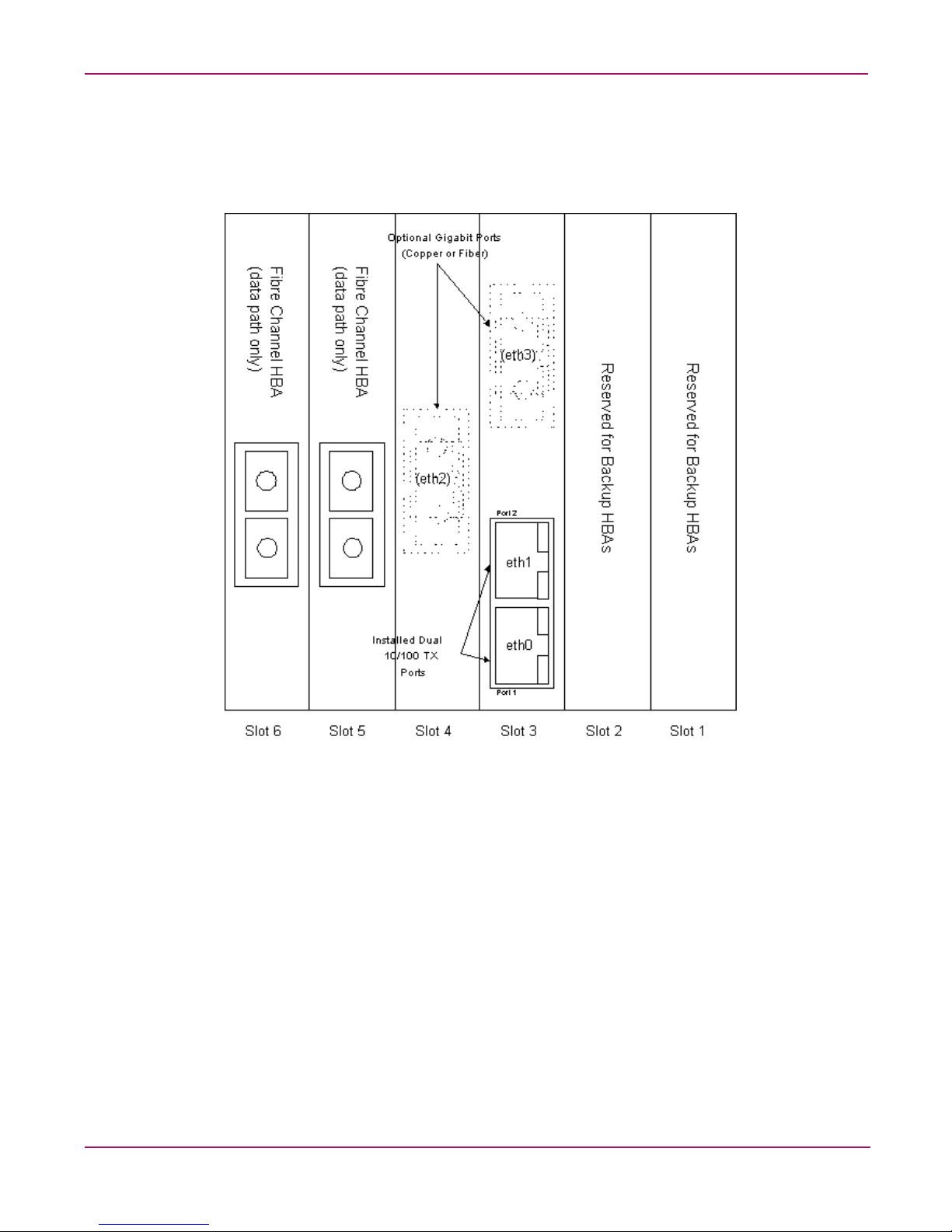
The following figure shows the physical port locations for the supported configurations, as
viewed from the back of the NAS server.
Figure 6: Port Locations for Supported Configurations on the NAS Server
Page 21

Network and Storage Planning
21HP StorageWorks NAS 8000 Dedicated Storage High Availability, Solution Integration Manual (SIM)
Planning Worksheets
The following topics should be reviewed in a planning session with the customer prior to
installation:
■ Available disk space
■ LUN, volume group and file volume requirements
■ High-availability settings
■ Network settings
The planning worksheets in this section provide space to collect the information needed to
install the system. The blank worksheets are also included on the NAS 8000 Documentation
CD.
Available Disk Space Spreadsheets
For the installation specialist: Before you begin the storage planning process with the
customer, you must know the amount of available disk space on their system. If you have not
received information about available disk space from the HP sales representative, use the
capacity calculation spreadsheet for the customer’s array model to calculate how much space
will be available for use.
This spreadsheet calculates the available disk space on the NAS 8000 HA system by
subtracting the space required for RAID redundancy and active spares from total raw capacity.
Note: These HP Confidential spreadsheets are available only to HP and resellers at:
http://csps.fc.hp.com/mass/disk.htm
Non-confidential Tables 3-6, below, can also be used to determine available disk space.
VA71xx supports up to 15 drives. VA7410 support up to 105 drives. You can extrapolate
higher capacity/drive count values from these tables.
Note: The numbers in these spreadsheets and tables are approximate. Verify the actual available
space on the system when it is installed before building the storage system.
Page 22

Network and Storage Planning
22 HP StorageWorks NAS 8000 Dedicated Storage High Availability, Solution Integration Manual (SIM)
VA7110 is not currently qualified on dedicated storage configurations.
Table 3: Capacity Table VA7100/VA7110 for RAID 1+0
Drive Size 36 GB 73 GB 146 GB
Hot Spares
21021021
0
No. of Drives Maximum Usable Capacity in GB
VA7100 min - 4 32.2 48.6 68.0 68.0 102.3 139.7 139.7 209.8 283.0
5 48.6 68.0 85.9 102.3 139.7 175.5 209.8 283.0 354.7
6 68.0 85.9 103.8 139.7 175.5 211.4 283.0 354.7 426.4
7 85.9 121.7 121.7 175.5 247.2 247.2 354.7 498.1 498.1
8 103.8 139.7 139.7 211.4 283.0 283.0 426.4 569.8 569.8
9 157.6 157.6 157.6 318.9 318.9 318.9 641.4 641.4 641.4
VA7110 min - 10 175.5 175.5 175.5 354.7 354.7 354.7 713.1 713.1 713.1
11 193.4 193.4 193.4 390.5 390.5 390.5 784.8 784.8 784.8
12 211.3 211.3 211.3 426.4 426.4 426.4 856.5 856.5 856.5
13 229.3 229.3 229.3 462.2 462.2 462.2 928.1 928.1 928.1
14 247.2 247.2 247.2 498.1 498.1 498.1 999.8 999.8 999.8
max VA7100 - 15 265.1 265.1 265.1 533.9 533.9 533.9 1071.5 1071.5 1071.5
VA7110 - 15 258.6 258.6 258.6 527.4 527.4 527.4 1065.0 1065.0 1065.0
VA7110 - 30 527.4 527.4 527.4 1065.0 1065.0 1065.0 2140.2 2140.2 2140.2
max VA7110 - 45 796.1 796.1 796.1 1602.5 1602.5 1602.5 3215.4 3215.4 3215.4
Table 4: Capacity Table VA7100/VA7110 for AutoRAID
Drive Size 36 GB 73 GB 146 GB
Hot Spares
21021021
0
No. of Drives Maximum Usable Capacity in GB
VA7100 min - 4 32.2 48.6 68.0 68.0 102.3 139.7 139.7 209.8 283.0
5 48.6 68.0 101.2 102.3 139.7 206.6 209.8 283.0 417.4
6 68.0 101.2 134.2 139.7 206.6 272.9 283.0 417.4 550.4
7 101.2 134.2 165.4 206.6 272.9 337.2 417.4 550.4 680.9
8 134.2 165.4 198.4 272.9 337.2 403.2 550.4 680.9 812.8
9 165.4 198.4 231.3 337.2 403.2 468.9 680.9 812.8 944.3
VA7110 min - 10 198.4 231.3 264.1 403.2 468.9 534.6 812.8 944.3 1075.6
11 231.3 264.1 296.9 468.9 534.6 600.1 944.3 1075.6 1206.7
12 264.1 296.9 329.6 534.6 600.1 665.6 1075.6 1206.7 1337.6
13 296.9 329.6 362.4 600.1 665.6 731.1 1206.7 1337.6 1468.5
14 329.6 362.4 395.1 665.6 731.1 796.5 1337.6 1468.5 1599.3
max VA7100 - 15 362.4 395.1 427.7 731.1 796.5 861.8 1468.5 1599.3 1730.0
VA7110 - 15 350.2 382.9 415.6 718.9 784.3 849.7 1456.4 1587.2 1717.9
VA7110 - 30 840.0 872.6 905.2 1698.2 1763.5 1828.7 3414.8 3545.2 3675.7
max VA7110 - 45 1329.0 1361.5 1394.1 2676.2 2741.4 2806.6 5370.7 5501.1 5631.4
Page 23

Network and Storage Planning
23HP StorageWorks NAS 8000 Dedicated Storage High Availability, Solution Integration Manual (SIM)
Table 5: Capacity Table VA7410 for Raid 1+0
Drive Size (GB) 36 GB 73 GB 144 MB
Hot Spares
210210210
No. of Drives Maximum Usable Capacity in GB
VA7410 min - 10 96.7 129.3 168.4 204.2 272.7 347.6 419.2 559.4 706.0
11 111.4 150.4 186.3 236.9 311.7 383.4 487.7 634.3 777.6
12 129.3 168.4 204.2 272.7 347.6 419.2 559.4 706.0 849.3
13 150.4 204.2 222.1 311.7 419.2 455.1 634.3 849.3 921.0
14 168.4 240.0 240.0 347.6 490.9 490.9 706.0 992.7 992.7
15 186.3 257.9 257.9 383.4 526.7 526.7 777.6 1064.4 1064.4
30 526.7 526.7 526.7 1064.3 1064.3 1064.3 2139.5 2139.5 2139.5
45 795.5 795.5 795.5 1601.9 1601.9 1601.9 3214.7 3214.7 3214.7
60 1064.3 1064.3 1064.3 2139.5 2139.5 2139.5 4289.9 4289.9 4289.9
75 1333.0 1333.0 1333.0 2677.0 2677.0 2677.0 5365.1 5365.1 5365.1
90 1601.8 1601.8 1601.8 3214.6 3214.6 3214.6 6440.2 6440.2 6440.2
105 1870.6 1870.6 1870.6 3752.2 3752.2 3752.2 7515.4 7515.4 7515.4
Table 6: Capacity Table VA7410 for AutoRAID
Drive Size (GB) 36 GB 73 GB 144 MB
Hot Spares
210210210
No. of Drives Maximum Usable Capacity in GB
VA7410 min - 10 96.7 129.3 198.3 204.2 272.7 409.1 419.2 559.4 830.8
11 111.4 164.6 230.5 236.9 341.7 474.7 487.7 695.8 963.0
12 129.3 198.3 263.8 272.7 409.1 541.3 559.4 830.8 1096.3
13 164.6 230.5 296.2 341.7 474.7 606.8 695.8 963.0 1227.9
14 198.3 263.8 329.3 409.1 541.3 673.0 830.8 1096.3 1360.3
15 230.5 296.2 357.1 474.7 606.8 733.8 963.0 1227.9 1487.1
30 718.2 783.6 849.0 1455.6 1586.5 1717.2 2930.5 3192.1 3453.5
45 1208.2 1273.5 1338.7 2435.5 2566.0 2696.5 4890.1 5151.1 5412.1
60 1697.5 1762.7 1827.9 3414.1 3544.4 3674.8 6847.1 7108.0 7368.9
75 2186.5 2251.7 2316.8 4392.0 4522.5 4652.9 8803.2 9064.9 9324.8
90 2675.4 2740.6 2805.7 5369.9 5500.3 5630.6 10758.9 11019.6 11280.4
105 3164.2 3229.3 3294.5 6347.6 6477.9 6608.3 12714.3 12975.0 13235.8
Page 24

Network and Storage Planning
24 HP StorageWorks NAS 8000 Dedicated Storage High Availability, Solution Integration Manual (SIM)
Storage Planning Worksheet
Note: All space is in Gigabytes (GB)
.
1. Record total available storage space Instructions
Total available storage Take the figure for available storage space from
the information provided by the HP sales
representative or from the spreadsheet.
2. Allocate space for creating LUNs Instructions
Space for LUNs LUN Size The total for all LUNs must not exceed the total
available system storage.
Storage (LUNs):
■ maximum 128 for single-array configurations
■ minimum 31 for multiple-array FC switch
configurations
LUN1:
LUN2:
LUN3:
3. Plan space for creating Volume Groups (VGs) Instructions
Space for VGs VG Name Size See Physical Storage on page 12 for tips on
planning Volume Groups and Failover Packages.
VG1:
VG2:
VG3:
4. Plan space to reserve for Snapshots
Snapshots are associated with a specific file volume and must be created in the same volume group as that file
volume. Therefore you must allocate enough space in each volume group to include all file volumes and snapshots.
Snapshots are optional. You can add or extend a snapshot at a later time if there is enough free space available
(minimum 16 MB) in the volume group. Record your reserved space in the table below. (See Snapshots on page 13
for more information.)
5. Calculate space and record share settings Instructions
Number of File Volumes
(FVs) in Volume Group
___
File Space Snapshot Win Share/
Unix Export
Name
Make a copy of this section for each Volume
Group.
These calculations will allow you to compare
the total amount of space you have to the
total amount of space you need. (See step 6,
below.)
Maximum FVs in each volume group: 64
File Volume 1:
File Volume 2:
File Volume 3:
File Volume 4:
File Volume 5:
Page 25

Network and Storage Planning
25HP StorageWorks NAS 8000 Dedicated Storage High Availability, Solution Integration Manual (SIM)
6. Verify total space for Snapshots and File Volumes Instructions
Total Used Space in
Volume Group ____
Total the lines in section 5. This number
should be equal to or less than line 1.
7. Remaining unallocated space Instructions
Total Remaining Space in
Volume Group _____
Subtract used space (line 6) from total
available space (line 1).
Page 26

Network and Storage Planning
26 HP StorageWorks NAS 8000 Dedicated Storage High Availability, Solution Integration Manual (SIM)
HA Planning Worksheet
Cluster Planning
Node 1 Name
Node 2 Name
Cluster Name
Quorum Server Name
Quorum Server Polling Interval (the time interval between
checks of the quorum server status)
(600s default)
Primary Heartbeat NIC
Recommendation: Use one of the included network ports (eth0) as
a direct-connect dedicated heartbeat NIC. See instructions in
Connect the Network Ports on page 47 for instructions on
connecting primary heartbeat NICs.
This cannot be the same NIC designated as the system
management network card (below).
Node 1:
Node 2:
Secondary (or backup) Heartbeat NICs
Recommendation: Use at least one additional NIC in each NAS
server as a secondary heartbeat NIC.
Secondary heartbeat NICs are not direct connections. See
instructions on Connect the Network Ports on page 47 for
instructions on connecting additional NICs.
Node 1:
Node 2:
System Management Port
The system management port is the port designated to access the
Command View NAS web interface.
This cannot be the same port designated as the primary
direct-connect heartbeat (above).
Node 1:
Node 2:
Heartbeat Interval (5s default)
Network Polling Interval (10s default)
Auto Start Time-out (600s default)
Maximum Number of Failover Packages (10 default)
Page 27

Network and Storage Planning
27HP StorageWorks NAS 8000 Dedicated Storage High Availability, Solution Integration Manual (SIM)
*To get to the subnet or network address, perform the following calculation:
Subnet (network address) = IP AND subnet mask
Failover Package Planning
Make a copy of this table for each Failover Package.
Failover Package Name
Fail Back Policy (manual or automatic)
Failover Policy (manual or automatic)
Auto Start (yes or no)
Reboot Node on Failure (yes or no)
Primary Node
Volume Groups 1.
2.
3.
4.
5.
6.
….
30.
Virtual IP Addresses and Subnet IP Address Subnet* (or
Network Address)
Page 28

Network and Storage Planning
28 HP StorageWorks NAS 8000 Dedicated Storage High Availability, Solution Integration Manual (SIM)
Network Planning Worksheet Node 1
NAS 8000 System Information
System Name
Administrator Password
Contact Information
Contact Name
Contact Phone Number
Contact Pager Number
Contact E-mail
Physical Location
Rack ID
Rack Position
Asset Number
SNMP Settings
SNMP Community Password
SNMP Trap Destination(s)
SMTP Settings
SMTP Server
E-mail Recipients
Remote Event Logging
Remote Log Server Address
Windows Settings
WINS Server IP Address
Network Neighborhood Description
Workgroup Name (Shared Level Security)
Domain Name (User Level Security)
UNIX Settings
NIS Domain Name
NIS Boot Server
Trusted Host(s)
Page 29

Network and Storage Planning
29HP StorageWorks NAS 8000 Dedicated Storage High Availability, Solution Integration Manual (SIM)
TCP/IP Settings NIC1 (installed network port eth0)
Note: Only one NIC per subnet can be configured. This limitation is required to prevent confusion as to which NIC to
bind a virtual IP address to when a failover package is started on a node or fails over. It is highly recommended that
‘eth0’ be configured as a dedicated heartbeat. See Figure 2 on page 10. Having a heartbeat on a dedicated network
port makes the heartbeat immune to heartbeat starvation due to high network traffic. To avoid subnet conflicts, use a
private subnet and IP address (e.g. 10.0.0.1) for the dedicated heartbeat, and direct connect the Ethernet CAT5
cross-over cable to the other node to eliminate the need for an Ethernet hub/switch that could fail.(See Connect the
Network Ports on page 47.) You may use an additional port to provide redundant heartbeats in case of primary
heartbeat failure.
IP Address
Gateway Address
Subnet Mask
Broadcast Address
DNS Domain Name
Primary DNS Server Address
Secondary DNS Servers
TCP/IP Settings NIC2
IP Address
Gateway Address
Subnet Mask
Broadcast Address
DNS Domain Name
Primary DNS Server Address
Secondary DNS Servers
TCP/IP Settings NIC3
IP Address
Gateway Address
Subnet Mask
Broadcast Address
DNS Domain Name
Primary DNS Server Address
Secondary DNS Servers
Page 30

Network and Storage Planning
30 HP StorageWorks NAS 8000 Dedicated Storage High Availability, Solution Integration Manual (SIM)
TCP/IP Settings NIC4
IP Address
Gateway Address
Subnet Mask
Broadcast Address
DNS Domain Name
Primary DNS Server Address
Secondary DNS Servers
Page 31

Network and Storage Planning
31HP StorageWorks NAS 8000 Dedicated Storage High Availability, Solution Integration Manual (SIM)
Network Planning Worksheet Node 2
NAS 8000 System Information
System Name
Administrator Password
Contact Information
Contact Name
Contact Phone Number
Contact Pager Number
Contact E-mail
Physical Location
Rack ID
Rack Position
Asset Number
SNMP Settings
SNMP Community Password
SNMP Trap Destination(s)
SMTP Settings
SMTP Server
E-mail Recipients
Remote Event Logging
Remote Log Server Address
Windows Settings
WINS Server IP Address
Network Neighborhood Description
Workgroup Name (Shared Level Security)
Domain Name (User Level Security)
UNIX Settings
NIS Domain Name
NIS Boot Server
Trusted Host(s)
Page 32

Network and Storage Planning
32 HP StorageWorks NAS 8000 Dedicated Storage High Availability, Solution Integration Manual (SIM)
TCP/IP Settings NIC1 (installed network port eth0)
Note: Only one NIC per subnet can be configured. This limitation is required to prevent confusion as to which NIC to
bind a virtual IP address to when a failover package is started on a node or fails over. It is highly recommended that
‘eth0’ be configured as a dedicated heartbeat. See Figure 2 on page 10. Having a heartbeat on a dedicated network
port makes the heartbeat immune to heartbeat starvation due to high network traffic. To avoid subnet conflicts, use a
private subnet and IP address (e.g. 10.0.0.1) for the dedicated heartbeat, and direct connect the Ethernet CAT5
cross-over cable to the other node to eliminate the need for an Ethernet hub/switch that could fail. (See Connect the
Network Ports on page 47.) You may use an additional port to provide redundant heartbeats in case of primary
heartbeat failure.
IP Address
Gateway Address
Subnet Mask
Broadcast Address
DNS Domain Name
Primary DNS Server Address
Secondary DNS Servers
TCP/IP Settings NIC2
IP Address
Gateway Address
Subnet Mask
Broadcast Address
DNS Domain Name
Primary DNS Server Address
Secondary DNS Servers
TCP/IP Settings NIC3
IP Address
Gateway Address
Subnet Mask
Broadcast Address
DNS Domain Name
Primary DNS Server Address
Secondary DNS Servers
Page 33

Network and Storage Planning
33HP StorageWorks NAS 8000 Dedicated Storage High Availability, Solution Integration Manual (SIM)
TCP/IP Settings NIC4
IP Address
Gateway Address
Subnet Mask
Broadcast Address
DNS Domain Name
Primary DNS Server Address
Secondary DNS Servers
Page 34

Network and Storage Planning
34 HP StorageWorks NAS 8000 Dedicated Storage High Availability, Solution Integration Manual (SIM)
Page 35

35HP StorageWorks NAS 8000 Dedicated Storage High Availability, Solution Integration Manual (SIM)
4
Installation Guide
This section explains the tasks required to install the HP StorageWorks NAS 8000 Solution.
Perform the following steps in sequence.
What to do: Who does it:
1. Review the planning worksheets Installation specialist and
customer IT administrator
2. Check the contents of each failover package Installation specialist
3. Rack the components Installation specialist
4. Connect the components Installation specialist
5. Define basic network and high-availability settings Installation specialist
6. Run the Command View NAS Configuration Wizard Installation specialist or
customer IT administrator
7. Build the storage system Installation specialist or
customer IT administrator
8. Enable the software modules Installation specialist or
customer IT administrator
Page 36

Installation Guide
36 HP StorageWorks NAS 8000 Dedicated Storage High Availability, Solution Integration Manual (SIM)
1. Review the Planning Worksheets
Review the planning worksheets completed with the customer in the planning session held
earlier to verify that no system requirements have been changed. You will need this
information to perform upcoming tasks:
■ Configure HA features
■ Define network settings
■ Build the storage system
Page 37

Installation Guide
37HP StorageWorks NAS 8000 Dedicated Storage High Availability, Solution Integration Manual (SIM)
2. Check the Contents of Each Package
The following sections provide an overview of the basic HP StorageWorks NAS 8000 system
components and shipping configurations. Review the detailed configuration information in
Solution Integration and Product Configuration Overview on page 9 to verify that you have
received all components needed to begin installation.
System Components
Main components:
■ Two NAS Servers with pre-installed NAS Operating System (OS) and Command View
NAS web interface
■ Quorum Server — HP server with HA cluster management software
■ Storage Array(s) -- Supported HP VA and XP arrays
.
Figure 7: Main Components
Optional components:
■ Up to six disk enclosures may be attached to each VA74XX series array
■ Two FC switches (required for multiple-array configurations).
■ Two APC Symmetra RM Uninterruptible Power Supplies (UPS)
■ HP Tape Library (SCSI or FC)
■ Rack(s) (not shown)
1. Quorum Server
2. NAS Server
3. Storage Array
1
2
3
Page 38

Installation Guide
38 HP StorageWorks NAS 8000 Dedicated Storage High Availability, Solution Integration Manual (SIM)
.
Figure 8: Optional Components
Accessories:
■ Cables and power cords
■ HP StorageWorks NAS 8000 documentation books and CD
■ Documentation for main components
Note: Each custom HP StorageWorks NAS 8000 configuration ships with the specific accessories
required to install and configure the system. See Solution Integration and Product Configuration
Overview on page 9 for a detailed parts list.
Figure 9: Typical Accessories Package
1. FC Switch
2. Disk Enclosure
3. Tape Library
4. UPS
1. Documentation 2. Cables and Power Cords
1
2
3
4
1
2
Page 39

Installation Guide
39HP StorageWorks NAS 8000 Dedicated Storage High Availability, Solution Integration Manual (SIM)
Shipping Configurations
The HP StorageWorks NAS 8000 components are delivered either pre-installed in a rack, or
separately to be racked on-site. For larg e conf igurations, you will need two racks and a rack tie
kit. Tape library and UPS components are shipped separately and must be racked on-site.
Racked systems:
■ Racked systems are shipped with the NAS server, storage array(s) and disk enclosure(s)
racked in an HP E-Series rack.
■ The Quorum server is shipped in a separate package and must be racked on-site.
■ Accessories and documentation are shipped in a separate package.
WARNING: The rack is heavy. Use care when taking the rack off of the pallet. Three people
are required for this step. Always use the anti-tip feet in the rack base.
Figure 10: Racked System
Page 40

Installation Guide
40 HP StorageWorks NAS 8000 Dedicated Storage High Availability, Solution Integration Manual (SIM)
Unracked systems:
■ The components of unracked systems are shipped in separate cartons.
■ In addition to the separate components, you also receive the HP StorageWorks NAS 8000
documentation.
■ Refer to the individual component packing lists for a detailed inventory of their parts.
Page 41

Installation Guide
41HP StorageWorks NAS 8000 Dedicated Storage High Availability, Solution Integration Manual (SIM)
3. Rack the Components
The Quorum server is shipped in a separate package and must be racked on-site.
With unracked solutions, you can install the other components in one of the following
supported racks:
■ HP E-Series Rack (recommended)
■ HP Computer Cabinet
■ Compaq Rack 9000 and 10000 Series
For detailed racking instructions and racking templates, see the documentation that shipped
with each component. For custom racking and cabling diagrams, see Solution Integration and
Product Configuration Overview on page 9.
Safety Tips
WARNING: It is the customer’s responsibility, working with their third party rack supplier,
to ensure proper rack installation, anti-tipping devices, power ratings, power connectors,
and secure earth ground are achieved for all installations in third party racks.
WARNING: Lift Components Properly. Do not attempt to lift any of the components by
yourself. Use an OSHA approved equipment-lifting device. Follow all OSHA lifting rules
and regulations.
If a rack loading hand truck is not available, two to three people are needed to lift heavy
components. Reduce weight by removing power supplies and hard disk modules from the
NAS server, array, UPS, and library for mounting.
Tipping hazard exists while removing rack from the pallet. Rack should be steadied and
kept from tipping by 2 or 3 people while removing rack from the pallet. Position people so
that rack does not tip over causing injury. Take special care as rack wheels roll off end of
ramp onto floor: Ensure wheels do not lock and cause tipping.
Tipping ha zard. Tipping of rack may cause severe injury or death. To prevent tipping,
anti-tipping feet must be installed on the rack prior to racking any of the components.
Prevent Tipping. To prevent the rack from rolling while you mount the components, make
sure the leveler screws on the rack’s lower four corners are in firm contact with the floor.
Proper installation of the anti-tip feet is required bef or e installing or ser vicing any de vice
in your racks. Use the anti-tip feet in the rack base (HP E Series racks, bol t on front and back;
HP Computer Cabinet, none; Compaq 9000 and 1000 series, front, left, right sides). Always
use the rack mounting handles that are supplied on rack-optimized units.
Pay particular attention to the racking instructions provided in the rack documentation. R ack
the heaviest components at the bottom of the rack and work upward, heaviest equipment to
lightest, without leaving empty space in the rack.
Never extend more than one piece of equipment on slides at one time. Always start
assembly at the bottom of the rack with the heaviest items and work upward: UPS, tape library ,
NAS servers, Quorum server, FC switches, storage array(s), disk enclosures.
Page 42

Installation Guide
42 HP StorageWorks NAS 8000 Dedicated Storage High Availability, Solution Integration Manual (SIM)
When moving the rack, push against the rack at the 1.6 meter (63 inch) height or lower.
Exercise extra caution when moving r ack sideways (racks are more stable from front to back
and when full).
For extra stability, attach your rack to other racks.
WARNING: High leakage current may exist. Ensure secure earth grounding. Ensure site
electrical circuits have reliable earth grounding. Never operate products in any rack
enclosure with the ground connector disconnected. Use only the power cords with L6-20,
L6-30, or IEC-309 connectors provided with the Power Distribution Units or UPS of your
NAS solution to connect to your power source.
Ensure proper PDU installation. HP PDUs are supplied with locking washers that break
through the powder coating of the PDU and the mounting columns on the rack. Follow all of
the installation instructions for the PDUs. Check for proper grounding between PDU and
rack. To ensure a redundant ground path, each rack solution should have a minimum of two
PDUs grounded to mains, even if all components are connected through one PDU.
Caution: Rack-optimized products are sensitive to static electricity. Wear a wrist-strap and
use a static-dissipating work surface connected to the server chassis when handling printed
circuit boards, memory devices, and processor chips or modules. Ensure that the metal wrist
strap contacts your skin and that the alligator clip is attached to a static-neutral surface.
Page 43

Installation Guide
43HP StorageWorks NAS 8000 Dedicated Storage High Availability, Solution Integration Manual (SIM)
4. Connect the Components
The following sections describe how to connect the system components:
■ Storage arrays
■ Tape library
■ Network ports
■ Power
The figures below provide sample configurations. See Solution Integration and Product
Configuration Overview on page 9 for detailed cabling diagrams for your configuration
Figure 11: Sample Connection Diagram — Single Array Configuration
Page 44

Installation Guide
44 HP StorageWorks NAS 8000 Dedicated Storage High Availability, Solution Integration Manual (SIM)
Figure 12: Sample Connection Diagram — Dual Array Configuration
If you are using Data Path Manager, the connection diagram will be slightly more complex.
See the HP NAS Data Path Manager Installa tion and User’s Guide for more information.
Connect the Array(s)
There are four different procedures for connecting storage arrays to NAS 8000
high-availability solutions:
■ Connect a single VA7100 array
■ Connect one or two VA7100 arrays with two FC switches
■ Connect a single VA74XX series array
■ Connect one or two VA74XX series arrays with two FC switches
These procedures are described on the following pages. See Solution Integration and Product
Configuration Overview on page 9 for detailed cabling diagrams.
Page 45

Installation Guide
45HP StorageWorks NAS 8000 Dedicated Storage High Availability, Solution Integration Manual (SIM)
Connecting VA7100 Arrays
To connect a single VA7100 array (see Figure 11 on page 43):
1. Connect the array to node 1:
— Remove the protective cover from the FC Port 1 connector on the array.
— Verify that a GBIC is connected to host FC Port 1 on the array, then plug one end of a
fiber optic cable into the GBIC.
— Plug the other end of the fiber optic cable into the mating optical connector on the
Fibre Channel HBA card in the NAS server designated as node 1.
2. Connect the array to node 2:
— Remove the protective cover from the FC Port 2 connector on the array.
— Verify that a GBIC is connected to host FC Port 2 on the array, then plug one end of a
fiber optic cable into the GBIC.
— Plug the other end of the fiber optic cable into the mating optical connector on the
Fibre Channel HBA card in the NAS server designated as node 2.
To connect one or two VA7100 arrays with an FC switch (see Figure 12 on page 44):
1. Connect the NAS servers to the FC switch:
— Each NAS server has two FC HBAs. On each NAS server, plug a f iber optic cable into
the optical connectors on each FC HBA.
— Plug the other end of each cable from NAS server 1 into the optical connectors on FC
switch 1.
— Plug the other end of each cable from NAS server 2 into the optical connectors on FC
switch 2.
2. Connect the arrays to the FC switches:
— Remove the protective cover from the FC Port connectors on each array.
— Verify that a GBIC is connected to the FC Port connectors on each array, then plug one
end of a fiber optic cable into each GBIC.
— Plug one cable from array 1 into an optical connector on FC switch 1 and plug the
second cable into a connector of FC switch 2.
— Plug one cable from array 2 into an optical connector on FC switch 1 and plug the
second cable into a connector of FC switch 2.
Figure 13: VA7100 FC Ports
1. FC Port 1 2. FC Port 2
1
2
Page 46

Installation Guide
46 HP StorageWorks NAS 8000 Dedicated Storage High Availability, Solution Integration Manual (SIM)
Connecting VA74xx Series Arrays
See Solution Integration and Product Configuration Overview on page 9 for detailed cabling
diagrams.
Follow these steps to connect a single VA74xx array (see Figure 11 on page 43).
1. Connect the array to node 1:
— Verify that a Transceiv er is installed on the FC Port 1 connector on the array, then plug
one end of a fiber optic cable into the Transceiver.
— Plug the other end of the fiber optic cable into the mating optical connector on the
Fibre Channel HBA card in the NAS server designated as node 1.
2. Connect the array to node 2:
— Verify that a Transceiv er is installed on the FC Port 2 connector on the array, then plug
one end of a fiber optic cable into the Transceiver.
— Plug the other end of the fiber optic cable into the mating optical connector on the
Fibre Channel HBA card in the NAS server designated as node 2.
Follow these steps to connect one or two VA74xx series arrays with a FC switch (see Figure 12
on page 44).
Note: This will be different when using Data Path Manager. Please see the HP NAS Data Path
Manager Installation and User’s Guide for detailed connection information.
1. Connect the NAS servers to the FC switch:
— Each NAS server has two FC HBAs. On each NAS server, plug a f iber optic cable into
the optical connectors on each FC HBA.
— Plug the other end of each cable from NAS server 1 into the optical connectors on FC
switch 1.
— Plug the other end of each cable from NAS server 2 into the optical connectors on FC
switch 2.
2. Connect the arrays to the FC switch:
— Verify that a Transceiver is installed on each FC Port connector on the array , then plug
a fiber optic cable into each Transceiver.
— Plug one cable from array 1 into an optical connector on FC switch 1 and plug the
second cable into a connector of FC switch 2.
— Plug one cable from array 2 into an optical connector on FC switch 1 and plug the
second cable into a connector of FC switch 2.
Page 47

Installation Guide
47HP StorageWorks NAS 8000 Dedicated Storage High Availability, Solution Integration Manual (SIM)
Figure 14: VA7410 FC Ports
Connect a Tape Library (optional)
You may connect a tape library to your NAS server by ordering the appropriate HBAs
(installed in PCI slots 1 & 2). The NAS 8000 supports either SCSI or fibre-channel HBAs.
The tape library can be shared by both NAS servers; however, the NAS 8000 nodes cannot
share a tape library with other components on a SAN.
See the tape library user’s guide for detailed connection instructions.
Figure 15: NAS Server Tape Library HBA Ports
Connect the Network Ports
Connect network cables to the network interface cards (NICs) on the NAS server to attach to
the network.
1. To connect the primary heartbeat NICs on both NAS servers, connect a CAT5 network
cross-over cable to the ports designated as the primary heartbeat on both NAS servers.
(See Planning Worksheets on page 21.)
2. To connect the NAS servers and Quorum server to the network, connect standard network
cables to network interface cards (NICs) on the NAS servers and the Quorum server.
1. Disk Enclosure FC Connectors 2. Host FC Connectors
1
2
1
2
1. Slots 1 and 2 reserved for
tape HBAs
1
Page 48

Installation Guide
48 HP StorageWorks NAS 8000 Dedicated Storage High Availability, Solution Integration Manual (SIM)
Figure 16: NAS Server NIC Ports
For detailed information on ethernet connectivity, see HA Storage Configuration on page 16.
Bonding the Network Ports
Two or more network ports may be connected to the sam e subnet only if they are bonded;
otherwise, the route table in the client and the NAS server will become confused. Instructions
for bonding and unbonding network ports is provided in HP NAS 8000 User’s Guide in the
Configuration chapter, NIC Bonding section.
Connect Power
Note: Each server node will have its own UPS monitoring connection.
Connect the UPS (optional).
1. Install the power and battery modules into the frame. See the UPS user’s guide for more
information.
— Power module: Slide the module into a bay until flush with frame. Tighten the two
screws to secure the module.
— Battery module: Lift the module and slide it completely into the frame. Align the tab
on top of the module with the connector inside the bay. Tighten the two screws to
secure the module.
Caution: Install battery modules just prior to running the UPS. The battery modules
discharge slowly when loaded prematurely and can be permanently damaged.
2. Form an ethernet connection between the UPS and the NAS Server through the local area
network. See Figure 2 on page 10 for a diagram showing the sample LAN connection for
your configuration.
— Select an ethernet port on the server to communicate with the UPS. See HA Storage
Configuration on page 16 for more information
— In Command View NAS, click the Configuration tab.
— Select UPS.
1. Slots 3 and 4 reserved for
NICs
1
Page 49

Installation Guide
49HP StorageWorks NAS 8000 Dedicated Storage High Availability, Solution Integration Manual (SIM)
— Select Actions > Edit UPS Properties.
— Input the correct information in the Edit UPS Properties dialog box, then click OK.
A separate UPS should be used with each NAS server.
3. Attach the UPS to a power source.
Symmetra RM UPS:
— If the planned power load is less than or equal to 5 kVA, plug the line into an
appropriate outlet.
— If the planned power load is greater than 5 kVA, a qualified electrician must hard-wire
the input power.
Symmetra UPS:
— Regardless of the power load, a qualified electrician must hard-wire the input power.
4. Connect the components to the Power Distribution Unit (PDU):
a. Connect the power cables of the components in each rack to the PDU strip on the rack
as shown in the diagrams in Solution Inte gration and Product Configuration Ov ervie w
on page 9.
b. Plug the PDU into the Power Distribution Panel (PDP) on the UPS.
c. Power up the components one at a time, in the following sequence, to minimize
current inrush:
— UPS systems
— Tape library
— FC switches
— disk enclosures
— Storage arrays
5. Quorum server
6. NAS servers
Caution: Do not boot the NAS servers until the storage array has finished powering up. As
the array is powering up, amber and green lights will turn on and blink. When only green
lights remain on, it is safe to boot the NAS servers.
Page 50

Installation Guide
50 HP StorageWorks NAS 8000 Dedicated Storage High Availability, Solution Integration Manual (SIM)
5. Define Basic Network and HA Settings
Configure the Quorum server
The Quorum server uses an industry standard Linux operating system. Complete the following
steps to configure the Quorum server:
1. Connect a terminal to the serial port.
2. Login as root. Use the default password printed on the sticker on the back of the server.
3. Enter QSconfig and follow the instructions to configure the networking and other
parameters of the Quorum server.
Note: When performing network configurations for the quorum server, you can also configure
system settings including the network hostname, IP address, and DNS using the HP config tool from
the quorum server. Login and run HPconfig from the command line interface. This will bring up a
menu of configuration options. Type “1” and press Enter to perform the network configuration.
4. Restart the Quorum server with the command reboot. Disconnect the terminal.
Configure the NAS servers
Before you can access the Command View NAS web interface, you must configure the
primary System Management network port on both NAS servers. In HA configurations, you
must disable DHCP and set up the network parameters manually.
Note: You will configure additional NICs using the Command View NAS web interface.
1. Connect a laptop with terminal emulation software to the server.
Connect an RS232 null-modem cable to the serial TTY Port on the server.
Figure 17: NAS Server Serial TTY Port
2. Use the terminal emulator to log in and enter network settings. Use the following settings:
— Bits per second: 9600
— Data bits: 8
— Parity: None
— Stop bits: 1
— Flow control: None
Page 51

Installation Guide
51HP StorageWorks NAS 8000 Dedicated Storage High Availability, Solution Integration Manual (SIM)
3. Press Enter until you see the system name and login prompt, as shown here, then log in as
admin. No password is required.
hp StorageWorks NAS 8000
NAS OS v1.x.x
localhost login:admin
4. Run the nasQuickStart command and follow the on-screen instructions.
You are prompted to:
■ Select and configure the Management Interface
— If a bond is selected, select slave interfaces
— Enable/disable DHCP
— If DHCP is not selected, enter the IP address, netmask, broadcast address, and
gateway address.
■ Enter the hostname
■ Enter the DNS domain name and server addresses
■ Configure remaining interfaces (like management interface, above)
■ Enter the timezone information
■ Scan for VA arrays
Note: Settings are applied as you enter them.
5. If no DNS server is available, or if you prefer not to use the DNS server, execute the
following commands, where:
— XXX represents IP address information.
— *name represents the name provided by the system administrator.
— domain represents the domain name provided by the system administrator.
setSystemHostsFileEntry quorumservername XXX.XXX.XXX.XXX domain
setSystemHostsFileEntry node1name XXX.XXX.XXX.XXX domain
setSystemHostsFileEntry node2name XXX.XXX.XXX.XXX domain
6. Repeat the above steps on each NAS server.
7. To log out of the system, type:
exit
Page 52

Installation Guide
52 HP StorageWorks NAS 8000 Dedicated Storage High Availability, Solution Integration Manual (SIM)
6. Run the Command View NAS Configuration Wizard
Run the Configuration Wizard:
1. Using a computer on the network, open a web browser.
2. Enter the IP address of either NAS server in the browser’s address location field to bring
up the Command View NAS web interface.
Note: The Command View NAS requires the Sun Microsystems Java™ Plug-in 1.3.1_04,
Standard Edition or later. Supported bro wsers include Internet Explorer 5.5 and Netscape 4.77.
If you do not have the plug-in, you will see a web page that helps you either
The first time you run the Command View NAS web interface, the Configuration Wizard
starts. The Configuration Wizard screen is shown in Figure 18, below.
Figure 18: Configuration Wizard
3. Use the Configuration Wizard to configure the HP StorageWorks NAS 8000. The Wizard
leads you through the configuration of:
— System settings
— Network settings
— Alert settings
Page 53

Installation Guide
53HP StorageWorks NAS 8000 Dedicated Storage High Availability, Solution Integration Manual (SIM)
4. Check Activate Cluster to save your settings and exit the Wizard.
You can make changes with the Command View NAS web interface later (see the HP
StorageWorks NAS 8000 User’s Guide).
If you are unable to access Command View NAS, use the command line interface to run
clusterQuickStart. This command allows you to perform basic cluster configuration.
Additional cluster features can be configured using the command line interface. Please see the
HP StorageWorks NAS 8000 Command Reference.
Note: We recommend running the system on default settings before implementing any changes to
the configuration.
Page 54

Installation Guide
54 HP StorageWorks NAS 8000 Dedicated Storage High Availability, Solution Integration Manual (SIM)
7. Build the Storage System
Use the information you gathered earlier on the storage planning worksheets to complete the
following tasks. These tasks must be completed before users can access storage:
■ Create LUNs on page 54
■ Create Volume Groups on page 54
■ Create and Start Failover Packages on page 55
■ Create File Volumes on page 55
■ Assign Shared Access on page 56
Create LUNs
1. Select Storage Array Summary.
2. Select Actions > Create New LUN.
3. Assign settings for the new LUN.
4. Select OK to save the new LUN.
Figure 19: LUN Settings
Repeat steps 2 and 3 to create additional LUNs.
Create Volume Groups
1. Select Volume Groups.
2. Select Actions > Create New Volume Group.
3. Enter a Volume Group Name and assign space from available LUNs.
Figure 20: Volume Group Settings
Page 55

Installation Guide
55HP StorageWorks NAS 8000 Dedicated Storage High Availability, Solution Integration Manual (SIM)
Repeat steps 2 and 3 to create additional volume groups.
Create and Start Failover Packages
1. Select Failover Packages.
2. Select Actions > Create New Package.
3. Define the settings for this Failover Package including name (maximum of 35 characters),
associated Volume Groups, and Virtual IP a ddress(es).
Figure 21: Failover Package Settings
4. As soon as you create a package, make a DNS entry for this package name and map it to
the virtual IP address.
5. Select Actions > Start Selected Package to start the Failover Package.
Repeat steps 2 through 5 to create additional Failover Packages.
Create File Volumes
Before you create a new file volume, you must add the volume group to a failover package.
1. Select File Volume Summary.
2. Select Actions > Create New File Volume.
3. Assign a File Volume Name, then select Quota Management and Capacity Policy
options.
4. Enter the Capacity of the file volume (in GB).
Page 56

Installation Guide
56 HP StorageWorks NAS 8000 Dedicated Storage High Availability, Solution Integration Manual (SIM)
Assign space to the volume using the information from the storage plann ing w orksh eet
inSolution Integration and Product Conf iguration Overvie w on page 9. Remember to leave
space for planned snapshots (see Snapshots on page 13).
Figure 22: File Volume Settings
Repeat steps 2 though 4 to create additional file volumes.
Assign Shared Access
A single file volume or directory can be both a Windows share and a UNIX® export.
To creating a Windows share:
1. Select Shares/Exports and highlight a file volume.
2. Select Actions > Create New SMB Share.
3. Enter a Share Name and define additional share settings.
Figure 23: Share Settings for Windows
To creating a UNIX export:
1. Select Shares/Exports and highlight a file volume.
2. Select Actions > Create New NFS Export.
3. Enter a Mount Name and define additional export settings.
Page 57

Installation Guide
57HP StorageWorks NAS 8000 Dedicated Storage High Availability, Solution Integration Manual (SIM)
Figure 24: Export Settings for UNIX
Page 58

Installation Guide
58 HP StorageWorks NAS 8000 Dedicated Storage High Availability, Solution Integration Manual (SIM)
8. Enable the Software Modules
The NAS 8000 solution includes the following software modules:
■ Virus scanning
■ Local backup agent (for use with the optional tape library)
■ Snapshots (for fast access to previous versions of files)
Use the Applications Tab to verify that all software modules are installed and to enable them:
1. Select the Applications Tab to view a list of all installed software modules.
If one of the software modules is not installed, contact HP support for the installation file
and instructions.
2. Enable the anti-virus and backup modules if you plan to use them:
— Click on the name of the module under the Installed Software folder.
— Select Actions > Enable/Disable Application.
Note: Snapshots are enabled by default.
Figure 25: Enabling Software Modules
3. Click Yes when prompted to enable the application.
Figure 26: Enable Confirmation Window
Page 59

Installation Guide
59HP StorageWorks NAS 8000 Dedicated Storage High Availability, Solution Integration Manual (SIM)
Next Steps
Installing Additional Software
If you have purchased additional software for the NAS 8000, you may install it now.
If HP NAS Data Path Manager is to be installed, please see the HP NAS Data Path Manager
Installation and User’s Guide.
Using the System
The NAS 8000 is installed. Use the Command View NAS web interface to perform additional
setup tasks and to maintain the system. The web interface lets you:
■ Configure additional settings.
■ Manage storage.
■ Monitor the system by viewing settings on the Status tab.
■ Use virus software, backup agents, and snapshots to protect your data.
■ Contact support, use diagnostic tools, and upgrade the server software.
For detailed instructions, see the HP StorageWorks NAS 8000 User’s Guide.
Where to Go for Help
■ General information: HP StorageWorks NAS 8000 User’s Guide
■ Context-sensitive Help: HP Command View NAS Help button
■ HP Online Support:
http://www.hp.com/support/nas8000
■ HP Customer Care:In the U.S. call (970) 635-1000
In other countries visit
http://www.hp.com/support/nas8000
■ HP Authorized Resellers:
http://www.hp.com
■ Ordering Products:
http://www.bstore.hp.com
Page 60

Installation Guide
60 HP StorageWorks NAS 8000 Dedicated Storage High Availability, Solution Integration Manual (SIM)
Page 61

61HP StorageWorks NAS 8000 Dedicated Storage High Availability, Solution Integration Manual (SIM)
5
Safety and Regulatory
Information
The HP StorageWorks NAS 8000 solution consists of a number of component items (servers,
disk arrays, etc.). Each of these component items have been independently tested for
regulatory approval.
Refer to the Regulatory Information statements and Certificates of Conformity contained
within the individual component manuals shipped with your system.
Note: Customers are not expected to troubleshoot individual components. Individual component
manuals are included for reference purposes only.
Page 62

Safety and Regulatory Information
62 HP StorageWorks NAS 8000 Dedicated Storage High Availability, Solution Integration Manual (SIM)
Page 63

63HP StorageWorks NAS 8000 Dedicated Storage High Availability, Solution Integration Manual (SIM)
index
Index
Index
A
Access
Assign 56
Storage 16
Accessory 38
Active Spare 12, 15, 21
Address
Configuration 50
IP 14
Virtual 16
Allocate
Space 13
Storage 13
APC Symmetra RM 37
Array 12, 15
Configuration 12, 16
Connect HA Solutions 44
Dual 45, 46
Multiple 37
Single 45, 46
Storage 15
VA 7100 Connection 45
VA 7400 Series Connection 46
Assign Shared Access 56
audience 5
authorized reseller, HP 6
Autogrow 13
AutoRAID 12, 15
B
Backup 11
Basic Settings 50
Battery 48
C
Cable 38
Calculate Available Disk Space 21
Capture 13
Caution
Booting the Server 49
Install Battery 48
Static Electricity 42
Certificates of Conformity 61
Cluster 14, 16
Command View NAS Configuration Wizard 52
Components 61
Connect System 43
Configuration 12
Connect Components 43
IP Address 50
NAS Server 50
Network Settings 50
Quorum Server 50
RAID Levels 15
Shipping 39
Storage 16
Wizard 52
Connect
Components 43
Network Ports 47
Power 48
Tape Library 47
Contact Information 59
conventions
document 5
Cord 38
Corruption 14
Current 42
D
Data
Backup 15
Capture 13
Corruption Protection 14
Protection 12, 13
Storage 12, 15
Page 64

Index
64 HP StorageWorks NAS 8000 Dedicated Storage High Availability, Solution Integration Manual (SIM)
Data Path Manager
connecting 44, 46
installing 59
Dedicated Hot Spare 15
Detect Failure 16
Directory
Definition 13
Overview 12
Disk Drives, Configuration 12
Disk Enclosure, DS2400 Series 37
Disk Space 21
document
conventions 5
prerequisites 5
related documentation 5
Documentation 38
E
Exports 12
F
Failover Packages 12, 13, 14, 16, 55
Create 55
Start 55
Failure 15
Detect 16
FC Switch 37
File Volume 11, 13
Create 55
Multiple 16
Overview 12
Terminology 12
G
getting help 6
H
Help 59
help, obtaining 5
High Availability 12, 14, 16
Connect Array 44
Planning Worksheet 26
High Leakage Current 42
HP
authorized reseller 6
storage website 6
technical support 6
HP SureStore Tape Library 37
HP Virtual Array 7100 12
HP Virtual Array 7400 Series 12
I
Install
Battery 48
Components 41
Internet Access 59
IP Address 14, 16
Configuration 50
J
JAVA 52
L
Leakage 42
Library 37, 47
Lifting 41
Logical Storage 12, 13
Logical Volume 15
LUN 12, 16
Create 16, 54
High Availability 15
Overview 12
M
Mirroring 15
N
NAS Server Configuration 50
Network
Ports 47
Settings 11, 50
Nodes 14, 16
P
Packages -- see Failover Packages 14
Parity 15
Parts List 38
PDU 49
Physical Storage 12
Planning 54
Network 11
Storage 11
Worksheets 11
Planning Worksheet 21, 24
High Availability 26
Power 48
Power Cord 38
Power Distribution Unit 49
prerequisites 5
Protection, Disk Failure 15
Page 65

Index
65HP StorageWorks NAS 8000 Dedicated Storage High Availability, Solution Integration Manual (SIM)
Q
Quorum Server 14, 41, 50
Quota Management 55
R
Rack 37, 39
Installation Safety 41
Racking 41
RAID 12
AutoRAID 12, 15
RAID 0 12
RAID 1 12
RAID 1+0 15
RAID 5 12, 15
RAID 5P 15
RAID Levels 15
RAID Settings 12
Redundancy 21
Read Me First 7
Rebuild 15
Regulations 61
related documentation 5
S
Safety 61
High Leakage Current 42
Lifting 41
Rack 39
Rack Installation 41
Static Electricty 42
Tipping 41
SCSI 37
Server 16
Caution 49
NAS 14, 50
Quorum 14, 41, 50
Settings
Failover Packages 55
LUN 54
Network 50
Terminal Emulator 50
Volume Group 54
Setup, Storage System 54
Shared Access
Assign 56
Shares 12
Shipping Configuration 39
Snapshot 11, 13, 24, 56
Software
Enable Modules 58
Terminal Emulator 50
Static Electricity 42
Storage 14, 16
Access 16, 54
Allocation 12, 13
Architecture 11, 12
Array 12, 15
Availability 14
Blocks 12
Build 54
Capacity 16
Configuration 16
Data 12, 15
Logical 12, 13
Overview 12
Physical 12
Planning 11, 24
Settings 11
Setup 11
Snapshot 13
Space 24
Terminology 12
Support 59
Switch, FC 37
Symmetra RM UPS 49
System
Accessory 38
Connect Components 43
Optional Components 37
Rack 39
Unracked 40
Usage 59
T
Tape Library 37, 47
technical support, HP 6
Terminal Emulator 50
Threshold, Autogrow 13
Tipping Hazard 41
Troubleshoot 61
U
Uninterruptible Power Supply (UPS) 37, 48
UPS 37, 48
V
Virtual Array 12
Virtual IP Address 14, 16
Volume Group 11, 12, 14, 16, 55
Create 16, 54
Multiple 16
Overview 12
Single 16
Page 66

Index
66 HP StorageWorks NAS 8000 Dedicated Storage High Availability, Solution Integration Manual (SIM)
W
Warning
High Leakage Current 42
Lifting 41
Rack 39
Rack Installation 41
Tipping 41
Web Site 59
websites
HP storage 6
Wizard 52
Worksheet 11, 21, 24
High Availability 26
 Loading...