

Page 1

HP StorageWorks 6000–series Virtual Library System User Guide
This document describes the HP StorageWorks VLS6000 systems to facilitate their installation, operation, and
maintenance. This document is intended for system administrators who are experienced with setting up and
managing large storage systems.
*AH809-96049*
Part Number: AH809-96049
Twelfth edition: September 2010
Page 2

Legal and notice information
© Copyright 2004, 2010 Hewlett-Packard Development Company, L.P.
The information contained herein is subject to change without notice. The only warranties for HP products and services are set
forth in the express warranty statements accompanying such products and services. Nothing herein should be construed as
constituting an additional warranty. HP shall not be liable for technical or editorial errors or omissions contained herein.
Acknowledgments
Microsoft® and Windows® are U.S. registered trademarks of Microsoft Corporation.
Warranty
WARRANTY STATEMENT: To obtain a copy of the warranty for this product, see the warranty information website:
http://www.hp.com/go/storagewarranty
Revision History
Revision History
release of firmware version 3.4.0
release of firmware version 3.3.1
release of firmware version 3.2.1
September 2010Revision AH809-96049
March 2010Revision AH809-96038
September 2009Revision AH809-96024
Page 3

Contents
1 Introduction ..................................................................................... 19
VLS6000 Models ...................................................................................................................... 19
VLS6100–series ................................................................................................................. 19
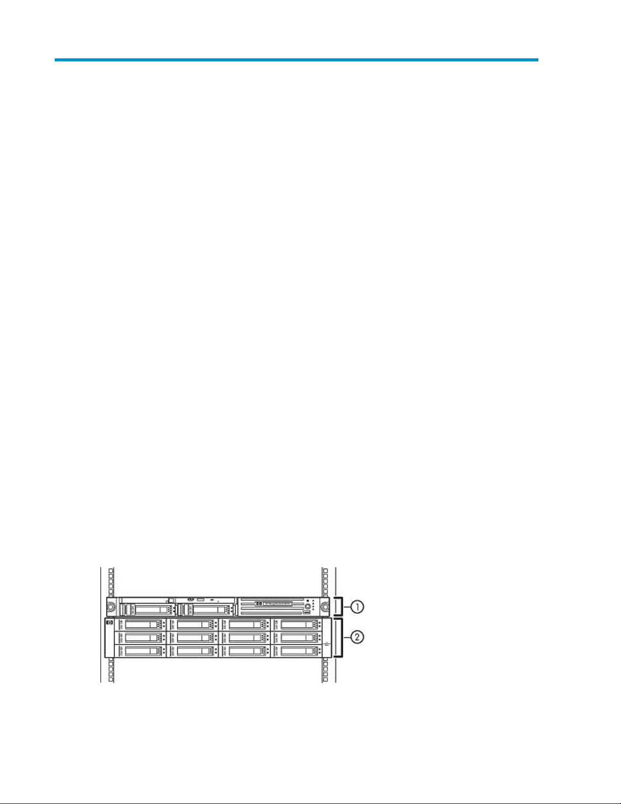
VLS6200–series ................................................................................................................. 20
VLS6500–series ................................................................................................................. 21
VLS6600–series ................................................................................................................. 23
VLS6800–series ................................................................................................................. 24
2 Hardware Installation ....................................................................... 29
Preparing for the Installation ....................................................................................................... 29
Tools for Installation ............................................................................................................ 29
Taking ESD Precautions ....................................................................................................... 29
Grounding Methods to Prevent Electrostatic Discharge ............................................................. 29
Unpacking ............................................................................................................................... 30
Removing the Packing Materials .................................................................................................. 30
Rack Planning Resources ............................................................................................................ 30
Rack Requirements .................................................................................................................... 31
Rack Warnings ......................................................................................................................... 31
Identifying the VLS Shipping Carton Contents ............................................................................... 31
VLS6100 and VLS6500 System Shipping Carton .................................................................... 32
VLS6200 System Shipping Carton ........................................................................................ 33
VLS6600 System Shipping Carton ........................................................................................ 33
VLS6800 System Shipping Carton ........................................................................................ 34
Disk Array Shipping Carton ................................................................................................. 35
Installing the Disk Arrays into a Rack ........................................................................................... 35
Rack Mounting Requirements ............................................................................................... 35
Mounting a Disk Array into a Rack ....................................................................................... 39
Installing the VLS6100 and VLS6500 Nodes into a Rack ............................................................... 44
Install Rails in the Rack ........................................................................................................ 44
Attach Rails to the Node ..................................................................................................... 45
Install Appliance in Rack ..................................................................................................... 45
Installing the VLS6600 Node into a Rack ..................................................................................... 46
Install Rails in the Rack ........................................................................................................ 46
Attach Rails to the VLS6600 Node (appliance) ....................................................................... 47
Install Appliance in the Rack ................................................................................................ 48
Installing the VLS6800 Node into a Rack ..................................................................................... 48
Install Rails in the Rack ........................................................................................................ 49
Install Appliance in Rack ..................................................................................................... 51
Installing the VLS6200 Node into a Rack ..................................................................................... 53
Installing VLS6100, VLS6200, VLS6500, and VLS6600 Cables ...................................................... 55
Installing VLS6800 Cables ......................................................................................................... 60
3 Storage Configuration ...................................................................... 65
Managing VLS6000–series Capacity .......................................................................................... 65
HP StorageWorks 6000–series Virtual Library System User Guide 3
Page 4

Configuring the RAID Level .................................................................................................. 65
Adding Capacity by Adding an Array .................................................................................. 67
Adding Capacity by Upgrading Disks in the Array ................................................................. 67
Removing Arrays ................................................................................................................ 68
Managing Storage Pools ..................................................................................................... 68
Viewing the Storage Pool .............................................................................................. 68
Rebuilding the Storage Pool .......................................................................................... 69
Installing Additional Licenses ...................................................................................................... 69
4 Automigration/Replication ................................................................ 73
Understanding Automigration Concepts ....................................................................................... 74
Echo Copy Concepts .......................................................................................................... 74
Smart Copy Concepts ......................................................................................................... 75
Replication Concepts .......................................................................................................... 75
Tape Initialization ............................................................................................................... 76
Connecting a Destination Library ................................................................................................ 77
Supported Destination Library Configurations ......................................................................... 77
Connecting a Destination Library to the VLS6000–series .......................................................... 77
Managing and Unmanaging a Destination Library ........................................................................ 78
Managing a SAN Library .................................................................................................... 79
Managing a LAN/WAN Replication Library .......................................................................... 79
Unmanaging a SAN or LAN/WAN Library ........................................................................... 80
Echo Copy Pool Operations ....................................................................................................... 81
Creating an Echo Copy Pool ................................................................................................ 82
Creating Virtual Tapes ........................................................................................................ 85
Restoring from a SAN Physical Cartridge ............................................................................... 85
Restoring from a LAN/WAN Virtual Cartridge ....................................................................... 86
Loading Blank Media into an Echo Copy Pool ........................................................................ 86
Loading Media into an Echo Copy Pool for Overwrite ............................................................. 87
Restarting a Broken Mirror ................................................................................................... 88
Viewing Cartridges in Automigration Source Libraries ............................................................. 88
Viewing Automigration Cartridges in the Firesafe .................................................................... 88
Smart Copy Pool Operations ...................................................................................................... 89
Editing SMI-S Settings ......................................................................................................... 89
Creating a Smart Copy Pool ................................................................................................ 89
Changing the Number of Drives in a Smart Copy Pool ............................................................ 90
Loading Blank Media into a Smart Copy Pool ........................................................................ 90
Loading Media into a Smart Copy Pool for Overwrite ............................................................. 91
Editing Copy Pools .................................................................................................................... 91
Moving a Copy Pool ........................................................................................................... 91
Changing the Slot Mapping for a SAN Library ...................................................................... 92
Changing the Slot Mapping for a LAN/WAN Library ............................................................. 93
Editing the SAN or LAN/WAN Policy ................................................................................... 94
Editing the SAN or LAN/WAN Availability Windows ............................................................. 94
Deleting a Copy Pool .......................................................................................................... 94
SAN Destination Library Operations ............................................................................................ 95
Monitoring Destination Library Status .................................................................................... 95
Cartridge Status and Slot Details ................................................................................... 95
Advanced Search for Slots ............................................................................................ 98
Mailslot Details ........................................................................................................... 99
Copy Pool Details ........................................................................................................ 99
Import/Export Pool Details ............................................................................................ 99
Tape Drive Details ........................................................................................................ 99
Forcing a Replication Job .................................................................................................... 99
4
Page 5

Placing a Library Offline or Online ....................................................................................... 99
Moving Media from One Slot to Another ............................................................................. 100
Ejecting Media from a Slot into an Empty Mailslot ................................................................ 101
Ejecting Media from a Drive into an Empty Mailslot .............................................................. 101
Restarting Automigration/Replication Services ...................................................................... 101
Scanning a SAN Destination Library ................................................................................... 102
Editing the Management URL ............................................................................................. 102
Uploading SAN Destination Library or Tape Drive Firmware ................................................... 102
Deploying SAN Destination Library or Tape Drive Firmware ................................................... 103
Generating a SAN Destination Library Support Ticket ............................................................ 103
Generating a SAN Destination Library Drive Support Ticket ................................................... 103
Running a SAN Destination Library Assessment Test .............................................................. 104
Running a SAN Destination Library Drive Assessment Test ...................................................... 104
LAN/WAN Destination Library Operations ................................................................................ 105
Exporting Data to Physical tapes for Tape Initialization .......................................................... 105
Stopping a Tape Export .................................................................................................... 106
Importing Data from Physical Tapes for Tape Initialization ...................................................... 106
Forcing Non-Deduplicated Replication ................................................................................ 106
Pausing, Resuming, and Canceling Replication Jobs .............................................................. 107
LAN/WAN Replication Target Operations ................................................................................. 107
Creating a LAN/WAN Replication Target ........................................................................... 107
Viewing the Replication Target Slot Details ........................................................................... 109
Setting the Global LAN/WAN Replication Target Configuration Settings ................................. 109
Editing a LAN/WAN Replication Target .............................................................................. 109
Deleting a LAN/WAN Replication Target ............................................................................ 110
Changing the LAN/WAN Replication Target Password ......................................................... 110
Clearing the Source VLS from the LAN/WAN Replication Target ............................................ 110
Automigration/Replication Reporting ......................................................................................... 111
Cartridge Status ............................................................................................................... 111
Cartridge Summary ................................................................................................... 112
Cartridge Details ....................................................................................................... 112
Configuring the Cartridge Status .................................................................................. 113
Viewing the Current Status of Jobs ...................................................................................... 113
Configuring Automigration Job Reports ............................................................................... 113
Viewing the Job History ..................................................................................................... 114
Exporting the Job History to a CSV File ......................................................................... 115
Viewing the Job Summary ................................................................................................. 115
Configuring the GUI Displays ............................................................................................. 115
5 Deduplication ................................................................................ 117
How It Works ......................................................................................................................... 117
Getting Deduplication Running on the VLS ................................................................................. 118
Considerations ................................................................................................................. 118
Installing the Firmware ...................................................................................................... 118
Installing the Deduplication Licenses ................................................................................... 119
Configuring Deduplication Options ........................................................................................... 119
Editing the Data Protector Configuration .............................................................................. 120
Viewing Deduplication Statistics and Reports .............................................................................. 120
Deduplication Summary .................................................................................................... 121
Deduplication Backup Report ............................................................................................. 121
Deduplication Cartridge Report .......................................................................................... 122
Deduplication System Capacity .......................................................................................... 123
6 Operation ..................................................................................... 125
HP StorageWorks 6000–series Virtual Library System User Guide 5
Page 6

Powering on VLS6000 Disk Arrays ............................................................................................ 125
Powering on the VLS6000–series System .................................................................................... 125
Rebooting the System .............................................................................................................. 129
Powering Off the System .......................................................................................................... 130
Powering Off VLS6000 Disk Arrays ........................................................................................... 131
7 User Interfaces ............................................................................... 133
User Interface Requirements ..................................................................................................... 133
Command View VLS ............................................................................................................... 133
Window Regions ............................................................................................................. 134
Opening a Command View VLS Session from a Web Browser ............................................... 135
Opening a Command View VLS Session from Command View TL ........................................... 136
Installing the SSL Certificate into your Web Browser .............................................................. 136
Restarting Command View VLS .......................................................................................... 137
Closing a Command View VLS Session ............................................................................... 138
Secure Shell and Serial User Interfaces ...................................................................................... 138
Opening a Secure Shell Session ......................................................................................... 138
Closing a Secure Shell Session ........................................................................................... 139
Opening a Serial Session .................................................................................................. 139
Closing a Serial Session .................................................................................................... 139
8 Configuration ................................................................................ 141
Setting the Network Settings ..................................................................................................... 141
Setting the Network Settings using the VLS Discovery Utility ................................................... 141
Setting the Network Settings using the CLI Command Set ...................................................... 143
Setting the Network Settings using Command View VLS ........................................................ 145
Setting the User Preferences ..................................................................................................... 146
Editing the Default Fibre Channel Host Port Settings ..................................................................... 147
Managing Oversubscription ..................................................................................................... 148
Enabling and Disabling Oversubscription ............................................................................ 148
Shutdown at 98% Capacity ............................................................................................... 149
Reclaiming Storage Space .......................................................................................... 149
Managing Virtual Device LUNs ................................................................................................. 150
Default LUN Numbering .................................................................................................... 150
Operating System LUN Requirements and Restrictions ............................................................ 151
LUN Masking .................................................................................................................. 151
LUN Masking (v3.x) ................................................................................................... 151
LUN Masking (v2.x) ................................................................................................... 152
LUN Mapping ................................................................................................................. 152
LUN Mapping (v3.x) .................................................................................................. 153
LUN Mapping (v2.x) .................................................................................................. 158
Dual Port Virtual Devices ................................................................................................... 159
Creating a Virtual Library ........................................................................................................ 160
Editing a Virtual Library's Slots and Drives ................................................................................. 162
Creating Tape Drives ............................................................................................................... 162
Creating Cartridges ................................................................................................................ 164
Destroying a Virtual Library ...................................................................................................... 167
Destroying a Tape Drive ........................................................................................................... 167
Deleting Cartridges ................................................................................................................. 168
Moving Cartridges .................................................................................................................. 169
Adding and Removing Barcode Templates ................................................................................. 170
9 Management ................................................................................. 171
6
Page 7

Changing the Account Passwords ............................................................................................. 171
Managing Cartridges .............................................................................................................. 171
Unloading a Cartridge from a Drive .......................................................................................... 172
Freeing up Storage Space ........................................................................................................ 172
Restarting VLS Device Emulations .............................................................................................. 172
Updating the Firmware ............................................................................................................ 173
Saving Configuration Settings ................................................................................................... 174
10 Monitoring .................................................................................. 175
Status Information in the Status Pane .......................................................................................... 175
Status Icons ............................................................................................................................ 175
Device Status Icon ............................................................................................................ 175
Navigation Tree Icon ........................................................................................................ 176
Notification Alerts ................................................................................................................... 176
Command View VLS ......................................................................................................... 177
E-mail Notification ............................................................................................................ 177
Editing the Email Server Settings .................................................................................. 178
Edit the Email Settings ................................................................................................ 178
SNMP Notification ........................................................................................................... 179
Editing the SNMP Settings .......................................................................................... 180
SMI-S Support .................................................................................................................. 181
Trace Log Files ........................................................................................................................ 182
Viewing Trace Log Files ..................................................................................................... 182
Saving a Trace Log File ..................................................................................................... 182
Creating a Support Ticket .................................................................................................. 182
Performance and Storage Use Reports ....................................................................................... 183
Exporting CSV Data ......................................................................................................... 183
Configuring Performance Reports and Notifications .............................................................. 183
Current Status Tab ...................................................................................................... 183
Performance History Tab ............................................................................................. 184
SAN Health Tab and Notifications ............................................................................... 184
Physical Capacity Notifications .................................................................................... 184
Logical Capacity Notifications ..................................................................................... 184
Current Status .................................................................................................................. 185
Performance History ......................................................................................................... 185
Logical Capacity .............................................................................................................. 186
Physical Capacity ............................................................................................................. 187
SAN Health ..................................................................................................................... 187
Workload Assessment ....................................................................................................... 189
Running a Workload Assessment Simulation .................................................................. 189
Using the Workload Assessment Templates ................................................................... 189
Editing the Notification Alerts ...................................................................................... 190
Replication History ........................................................................................................... 190
Receiving Automated Reports ............................................................................................. 190
Stress Testing Hard Disks ......................................................................................................... 192
Configuring the Storage Exerciser ....................................................................................... 192
Storage Exerciser CLI Commands ................................................................................. 193
Starting and Reviewing Read-only Jobs ................................................................................ 194
Starting and Reviewing Background Jobs ............................................................................. 194
Log Monitor Summary ................................................................................................ 195
Log File Fields .................................................................................................................. 195
Clearing the Hardware Compression Faults ................................................................................ 196
11 CLI Command Set ........................................................................ 199
HP StorageWorks 6000–series Virtual Library System User Guide 7
Page 8

Commands ............................................................................................................................ 199
Conventions .................................................................................................................... 199
CLI-only Commands ................................................................................................................ 199
Connection Commands ..................................................................................................... 199
Output Commands ........................................................................................................... 200
VLS Commands ...................................................................................................................... 200
Network Settings Configuration Commands ......................................................................... 200
Configuration Commands .................................................................................................. 202
Management Commands .................................................................................................. 209
Monitoring Commands ..................................................................................................... 210
12 Component Identification .............................................................. 213
VLS6100 and VLS6500 Node Components, LEDs, and Buttons .................................................... 213
Front Panel Components .................................................................................................... 213
Front Panel LEDs and Buttons ............................................................................................. 214
Rear Panel Components .................................................................................................... 215
Rear Panel LEDs and Buttons .............................................................................................. 216
System Board Components ................................................................................................ 217
System Board LEDs ........................................................................................................... 218
Node LEDs and Internal Health LED Combinations ................................................................ 219
Fan Module Locations ....................................................................................................... 220
Processor Zone Fan Module LED ........................................................................................ 221
VLS6200 Node Components, LEDs, and Buttons ......................................................................... 221
Front Panel Components .................................................................................................... 221
Front Panel LEDs and Buttons ............................................................................................. 222
Rear Panel Components .................................................................................................... 223
Rear Panel LEDs and Buttons .............................................................................................. 224
System Board Components ................................................................................................ 225
Accessing the VLS6200 HP Systems Insight Display .............................................................. 226
HP Systems Insight Display and LEDs ................................................................................... 226
HP Systems Insight Display LEDs and Internal Health LED Combinations ................................... 227
Hard Drive LEDs ............................................................................................................... 229
Hard Drive LED Combinations ............................................................................................ 229
Fan Locations ................................................................................................................... 230
VLS6600 Node Components, LEDs, and Buttons ......................................................................... 230
Front Panel Components .................................................................................................... 230
Front Panel LEDs and Buttons ............................................................................................. 231
HP Systems Insight Display and LEDs ................................................................................... 232
Rear Panel Components .................................................................................................... 233
Rear Panel LEDs and Buttons .............................................................................................. 234
System Board Components ................................................................................................ 235
FBDIMM Slots ........................................................................................................... 236
HP Systems Insight Display LEDs and Internal Health LED Combinations ................................... 237
Hard Drive LEDs ............................................................................................................... 238
Hard Drive LED Combinations ............................................................................................ 239
Fan Locations ................................................................................................................... 240
VLS6800 Node Components, LEDs, and Buttons ......................................................................... 240
Front Panel Components .................................................................................................... 240
Front Panel LEDs and Buttons ............................................................................................. 241
Rear Panel Components .................................................................................................... 244
Rear Panel LEDs and Buttons .............................................................................................. 245
System Board Components ................................................................................................ 245
Processor Memory Board Components ................................................................................ 246
QuickFind Diagnostic Display LEDs ..................................................................................... 247
8
Page 9

Fan Locations ................................................................................................................... 249
Fan LED .......................................................................................................................... 250
VLS6000–series Disk Array Components, LEDs, and Buttons ......................................................... 250
Front Panel Components .................................................................................................... 250
Front Panel LEDs ............................................................................................................... 251
Rear Panel Components .................................................................................................... 252
Rear Panel LEDs and Buttons .............................................................................................. 252
13 Component Replacement .............................................................. 255
Safety Considerations .............................................................................................................. 255
Preventing Electrostatic Discharge ....................................................................................... 255
Grounding Methods to Prevent Electrostatic Damage ............................................................. 255
Warnings and Cautions .................................................................................................... 256
Preparation Procedures ............................................................................................................ 256
Locating and Removing the Torx T-15 Tool (VLS6800 node only) ............................................ 257
Extending a VLS6100, VLS6200, or VLS6500 Node from the Rack ........................................ 257
Extending a VLS6600 Node from the Rack .......................................................................... 258
Extending the VLS6800 Node from the Rack ........................................................................ 259
Removing a VLS6100, VLS6200, or VLS6500 Node from the Rack ......................................... 261
Removing a VLS6600 Node from the Rack .......................................................................... 262
Removing a VLS6800 Node from the Rack .......................................................................... 262
Removing the VLS6100, VLS6200, or VLS6500 Node Access Panel ....................................... 262
Removing the VLS6600 Node Access Panel ......................................................................... 263
Removing the VLS6800 Node Access Panel ......................................................................... 264
Installing the VLS6100, VLS6200, or VLS6500 Node Access Panel ........................................ 265
Installing the VLS6600 Node Access Panel .......................................................................... 265
Installing the VLS6800 Node Access Panel .......................................................................... 265
VLS6100 and VLS6500 Node Component Replacement .............................................................. 265
SATA Hard Drive .............................................................................................................. 265
CD-ROM Drive ................................................................................................................. 266
Power Supply ................................................................................................................... 267
Power Supply Zone Fan Module ......................................................................................... 268
Processor Zone Fan Module ............................................................................................... 269
DIMM ............................................................................................................................. 270
VLS6200 Node Component Replacement .................................................................................. 271
SATA Hard Drive .............................................................................................................. 271
DVD-CD Drive .................................................................................................................. 272
Power Supply ................................................................................................................... 273
Fan Module ..................................................................................................................... 275
FBDIMM ......................................................................................................................... 277
VLS6600 Node Component Replacement .................................................................................. 278
SATA Hard Drive .............................................................................................................. 278
DVD-CD Drive .................................................................................................................. 279
Power Supply ................................................................................................................... 281
Fan ................................................................................................................................ 282
FBDIMM ......................................................................................................................... 283
VLS6800 Node Component Replacement .................................................................................. 284
SCSI Hard Drive ............................................................................................................... 284
Diskette Drive ................................................................................................................... 286
DVD-CD Drive .................................................................................................................. 286
Power Supply ................................................................................................................... 287
Fan ................................................................................................................................ 288
Processor Memory Board .................................................................................................. 289
Processor Power Module ................................................................................................... 290
HP StorageWorks 6000–series Virtual Library System User Guide 9
Page 10

DIMM ............................................................................................................................. 291
Processor ........................................................................................................................ 292
VLS6000–series Disk Array Component Replacement .................................................................. 294
Hard Drive ...................................................................................................................... 294
Fan Module ..................................................................................................................... 295
Power Supply ................................................................................................................... 296
Controller Module ............................................................................................................ 297
14 Disaster Recovery ......................................................................... 299
Recovering from Operating System Failure ................................................................................. 299
Restoring the Configuration Settings .................................................................................... 300
Restoring the Virtual Library Configuration from a Configuration File ................................. 300
Rebuilding the Virtual Library Configuration .................................................................. 300
Re-installing the VLS Licenses .............................................................................................. 301
Warm Failover ................................................................................................................. 301
Recovering from a VLS6000 Disk Array RAID Volume Failure ........................................................ 301
Recovering from a Node RAID Volume Failure ............................................................................ 302
15 Support and Other Resources ........................................................ 303
Related Information ................................................................................................................. 303
Documents ...................................................................................................................... 303
Websites ......................................................................................................................... 303
Document Conventions and Symbols ......................................................................................... 304
Rack Stability ......................................................................................................................... 305
Contacting HP ........................................................................................................................ 306
Before you Contact HP ...................................................................................................... 306
HP Contact Information ..................................................................................................... 306
Subscription Service ................................................................................................................ 306
Customer Self Repair ............................................................................................................... 307
HP Insight Remote Support software .......................................................................................... 307
Product Warranties ................................................................................................................. 307
Documentation Feedback ......................................................................................................... 308
A Troubleshooting ............................................................................. 309
VLS Common Issues ................................................................................................................ 309
Automigration/Replication Issues .............................................................................................. 316
Destination library status icon ............................................................................................ 316
Replacing a library ........................................................................................................... 317
Deduplication Issues ................................................................................................................ 317
B Specifications ................................................................................ 319
VLS6100 and VLS6500 Node .................................................................................................. 319
VLS6200 Node ...................................................................................................................... 320
VLS6600 Node ...................................................................................................................... 321
VLS6800 Node ...................................................................................................................... 322
VLS6000–series Disk Array ...................................................................................................... 323
Environmental Specifications .................................................................................................... 323
C Regulatory Compliance Notices ....................................................... 325
Regulatory Compliance Identification Numbers ........................................................................... 325
Federal Communications Commission Notice ............................................................................. 325
FCC rating label .............................................................................................................. 325
10
Page 11

Class A equipment ..................................................................................................... 325
Class B equipment ..................................................................................................... 326
Declaration of Conformity for products marked with the FCC logo, United States only ............... 326
Modification .................................................................................................................... 326
Cables ............................................................................................................................ 326
Canadian Notice (Avis Canadien) ............................................................................................ 326
Class A Equipment ........................................................................................................... 326
Class B Equipment ............................................................................................................ 327
European Union Notice ........................................................................................................... 327
Japanese Notices ................................................................................................................... 327
Japanese VCCI-A Notice ................................................................................................... 327
Japanese VCCI-B Notice ................................................................................................... 327
Japanese Power Cord Statement ......................................................................................... 327
Korean Notices ...................................................................................................................... 328
Class A Equipment ........................................................................................................... 328
Class B Equipment ............................................................................................................ 328
Taiwanese Notices .................................................................................................................. 328
BSMI Class A Notice ........................................................................................................ 328
Taiwan Battery Recycle Statement ....................................................................................... 328
Laser Compliance Notices ....................................................................................................... 329
English Laser Notice ......................................................................................................... 329
Dutch Laser Notice ........................................................................................................... 329
French Laser Notice .......................................................................................................... 330
German Laser Notice ........................................................................................................ 330
Italian Laser Notice .......................................................................................................... 330
Japanese Laser Notice ...................................................................................................... 331
Spanish Laser Notice ........................................................................................................ 331
Recycling Notices ................................................................................................................... 331
English Notice ................................................................................................................. 331
Bulgarian Notice .............................................................................................................. 332
Czech Notice .................................................................................................................. 332
Danish Notice ................................................................................................................. 332
Dutch Notice ................................................................................................................... 332
Estonian Notice ............................................................................................................... 333
Finnish Notice ................................................................................................................. 333
French Notice .................................................................................................................. 333
German Notice ................................................................................................................ 333
Greek Notice ................................................................................................................... 334
Hungarian Notice ............................................................................................................ 334
Italian Notice ................................................................................................................... 334
Latvian Notice ................................................................................................................. 334
Lithuanian Notice ............................................................................................................. 335
Polish Notice ................................................................................................................... 335
Portuguese Notice ............................................................................................................ 335
Romanian Notice ............................................................................................................. 335
Slovak Notice .................................................................................................................. 336
Spanish Notice ................................................................................................................ 336
Swedish Notice ................................................................................................................ 336
Turkish Notice .................................................................................................................. 336
Battery Replacement Notices .................................................................................................... 337
Dutch Battery Notice ......................................................................................................... 337
French Battery Notice ....................................................................................................... 338
German Battery Notice ..................................................................................................... 338
Italian Battery Notice ........................................................................................................ 339
Japanese Battery Notice ................................................................................................... 339
HP StorageWorks 6000–series Virtual Library System User Guide 11
Page 12

Spanish Battery Notice ..................................................................................................... 340
Glossary .......................................................................................... 341
Index ............................................................................................... 347
12
Page 13

Figures
VLS6100, VLS6200, and VLS6500 disk array rack mounting order ............................... 361
VLS6600 disk array rack mounting order ................................................................... 372
VLS6800 disk array rack mounting order ................................................................... 383
Positioning the rack mounting template ...................................................................... 404
Engaging the rack rail with the marked hole in the front of the rack ............................... 415
Engaging the rack rail with the marked hole in the rear of the rack ................................ 416
Loosening the locknut on the shipping bracket ............................................................ 427
Aligning the disk array with the rails ......................................................................... 428
Removing the mounting bracket covers ....................................................................... 439
Sliding the bracket forward to engage with the disk array ............................................ 4310
Install rails ............................................................................................................. 4411
Remove slides from rails ........................................................................................... 4512
Attaching rails to the node ....................................................................................... 4513
Attaching the rear bracket of the slide rail to the rack .................................................. 4714
Attaching rails to the VLS6600 node ......................................................................... 4715
Measuring with the template .................................................................................... 4916
Pulling the rail compression lever ............................................................................... 4917
Inserting the rail tabs on the rear of the rack ............................................................... 5018
Inserting the rail tabs on the front of the rack .............................................................. 5019
Attaching a node rail to the node ............................................................................. 5120
Locking the inner slide rails into place ....................................................................... 5221
Loading the node onto the rack rails .......................................................................... 5222
Sliding the node to the rear of the rack ...................................................................... 5323
Tightening the thumbscrews ...................................................................................... 5324
VLS6100 and VLS6500 — Connecting SAN and LAN cabling to the node .................... 5525
VLS6200 — Connecting SAN and LAN cabling to the node ........................................ 5526
VLS6600 — Connecting SAN and LAN cabling to the node ........................................ 5627
VLS6100 and VLS6500 — Connecting the VHDCI connectors to disk arrays .................. 5728
VLS6200 — Connecting the VHDCI connectors to disk arrays ....................................... 5729
VLS6600 — Connecting the VHDCI connectors to disk arrays ....................................... 5830
Connecting the node power supplies to an AC power source ........................................ 5931
Securing the power cord with the strain relief clip ........................................................ 5932
HP StorageWorks 6000–series Virtual Library System User Guide 13
Page 14

Connecting the disk array power supplies to an AC power source ................................. 5933
Connecting SAN and LAN cabling to the node .......................................................... 6034
Connecting the VHDCI connector on each disk array to the appropriate VHDCI connector
35
on the node ........................................................................................................... 61
Connecting power supply AC power connectors to AC power sources ........................... 6336
Securing the power cords ......................................................................................... 6337
Connecting the disk array power supplies to an AC power source ................................. 6338
Disk array volume configuration: 4 data + 2 parity disks and 5 data +1 parity disks ....... 6639
Disk array volume configuration: 3 data + 1 parity disks .............................................. 6640
Storage Pool details window .................................................................................... 6941
Config port mode ................................................................................................... 7842
Configuring deduplication options .......................................................................... 11943
VLS6100 and VLS6500 node LED status during normal operation ............................... 12644
VLS6200 node LED status during normal operation ................................................... 12645
VLS6600 node LED status during normal operation ................................................... 12746
VLS6800 node LED status during normal operation ................................................... 12847
VLS discovery utility — main window ...................................................................... 14248
VLS discovery utility – Device Configuration window .................................................. 14349
Set Network Configuration Wizard window ............................................................. 14550
Fibre Channel Host Ports window ............................................................................ 14751
Host LUN Mapping Mode window .......................................................................... 15252
LUN Mapping Device View window ........................................................................ 15453
LUN Mapping Host View window ........................................................................... 15554
LUN Mapping Host Setup window .......................................................................... 15755
Library Parameters – Map LUNs window .................................................................. 15956
Create Virtual Library Wizard window (1 of 12) ....................................................... 16057
Create Virtual Library Wizard window (2 of 12) ....................................................... 16158
Create Virtual Library Wizard window (5 of 12) ...................................................... 16359
Create Virtual Library Wizard window (6 of 12) ....................................................... 16360
Create Virtual Library Wizard window (8 of 12) ....................................................... 16561
Create Virtual Library Wizard window (9 of 12) ....................................................... 16662
Create Virtual Library Wizard window (10 of 12) ..................................................... 16663
Device status icon in the status banner ..................................................................... 17664
Navigation tree icon ............................................................................................. 17665
14
Notification alert examples .................................................................................... 17766
Edit Email Settings window .................................................................................... 17967
Edit SNMP Settings window ................................................................................... 18068
Page 15

CSV data fields for VLS performance reports ............................................................ 18569
SAN Health tab .................................................................................................... 18870
Removing the Torx T-15 tool ................................................................................... 25771
Extending the node from the rack ............................................................................ 25872
Sliding the node back into the rack ......................................................................... 25973
Loosening the front panel thumbscrews ..................................................................... 26074
Extending the node from the rack ............................................................................ 26075
Sliding the node into the rack ................................................................................. 26176
Tightening the thumbscrews .................................................................................... 26177
Removing the access panel .................................................................................... 26478
Removing a node hard drive .................................................................................. 26679
Ejecting the CD-ROM drive ..................................................................................... 26780
Removing a node power supply .............................................................................. 26781
Installing an AC power supply ................................................................................ 26882
Placing the power cord in the strain relief clip ........................................................... 26883
Removing the node power supply zone fan module ................................................... 26984
Removing the processor zone fan module ................................................................. 27085
Removing the node DIMM ..................................................................................... 27086
Removing a Node Hard Drive ................................................................................ 27187
Preparing the Node Hard Drive .............................................................................. 27288
Installing the Node Hard Drive ............................................................................... 27289
Removing a node hard drive .................................................................................. 27990
Installing a node hard drive .................................................................................... 27991
Removing the DVD-CD drive ................................................................................... 28092
Installing the DVD-CD drive .................................................................................... 28093
Removing a node power supply .............................................................................. 28194
Installing a node power supply ............................................................................... 28295
Installing the node FBDIMM ................................................................................... 28496
Removing a hard drive .......................................................................................... 28597
Installing a hard drive ............................................................................................ 28598
Removing the diskette drive .................................................................................... 28699
Removing the DVD-CD drive ................................................................................... 287100
Removing a power supply ...................................................................................... 288101
Removing a fan .................................................................................................... 289102
Removing a processor memory board ...................................................................... 290103
Removing a processor power module ...................................................................... 291104
Removing a DIMM ................................................................................................ 291105
HP StorageWorks 6000–series Virtual Library System User Guide 15
Page 16

Removing the processor heatsink ............................................................................. 293106
Removing a processor ........................................................................................... 293107
Removing a disk array hard drive ............................................................................ 295108
Removing a disk array fan module .......................................................................... 296109
Removing a disk array power supply ....................................................................... 296110
Removing the disk RAID controller module ................................................................ 297111
16
Page 17

Tables
VLS6200–series capacity (based on RAID5 configuration; capacity is lower in RAID6
1
configuration) ......................................................................................................... 21
VLS6500–series capacity (based on RAID5 configuration; capacity is lower in RAID6
2
configuration) ......................................................................................................... 22
VLS6600–series capacity (based on RAID5 configuration; capacity is lower in RAID6
3
configuration) ......................................................................................................... 23
VLS6800–series capacity (based on RAID5 configuration; capacity is lower in RAID6
4
configuration) ......................................................................................................... 26
VLS user interface requirements ............................................................................... 1335
CLI connection commands ...................................................................................... 1996
CLI output commands ............................................................................................ 2007
CLI network settings configuration commands ........................................................... 2018
CLI configuration commands .................................................................................. 2029
CLI management commands .................................................................................. 20910
CLI monitoring commands ...................................................................................... 21011
Power supply LED combinations .............................................................................. 24212
Hard drive LED combinations .................................................................................. 24313
Hard Drive LED Combinations ................................................................................ 25114
Document Conventions .......................................................................................... 30415
HP StorageWorks 6000–series Virtual Library System User Guide 17
Page 18

18
Page 19
1 Introduction
The HP StorageWorks virtual library system (VLS) family consists of RAID disk-based SAN backup
devices that emulate physical tape libraries, allowing you to perform disk-to-virtual tape (disk-to-disk)
backups using your existing backup applications. The VLS family includes different series of models
that vary in storage capacity and performance.
The VLS emulates a variety of physical tape libraries, including the tape drives and cartridges inside
the libraries. You determine the number and types of tape libraries a VLS emulates, and the number
and types of tape drives and cartridges included in each tape library to meet the needs of your
environment. You configure the size of the virtual cartridges in your VLS, which provides even more
flexibility.
The VLS automigration features allow you to establish data pools to create and manage mirror (echo
copy) or snapshot (smart copy) replication of data for additional protection against data loss.
Deduplication provides the functionality in which only a single copy of a data block is stored on a
device. Duplicate information is removed, thereby reducing the amount of storage used by a given
data block.
The VLS accommodates mixed IT platform and backup application environments, allowing all your
servers and backup applications to access the virtual media simultaneously. You can specify which
servers are allowed to access each virtual library and tape drive you configure. You can change the
default LUNs assigned to the virtual library and tape drives for each host as needed to accommodate
different operating system requirements and restrictions.
Data stored on a VLS is easily cloned to physical tape for off-site disaster protection or long-term
archival using a backup application.
This section describes the HP StorageWorks 6000–series virtual library system models.
VLS6000 Models
VLS6100–series
A VLS6100–series consists of a VLS6100–series node (head unit) and one Modular Smart Array 20
(MSA20) disk array. The node includes a single processor, two 2 GB Fibre Channel host ports, and
two VHDCI connectors. The disk array contains twelve SATA disks.
HP StorageWorks 6000–series Virtual Library System User Guide 19
Page 20
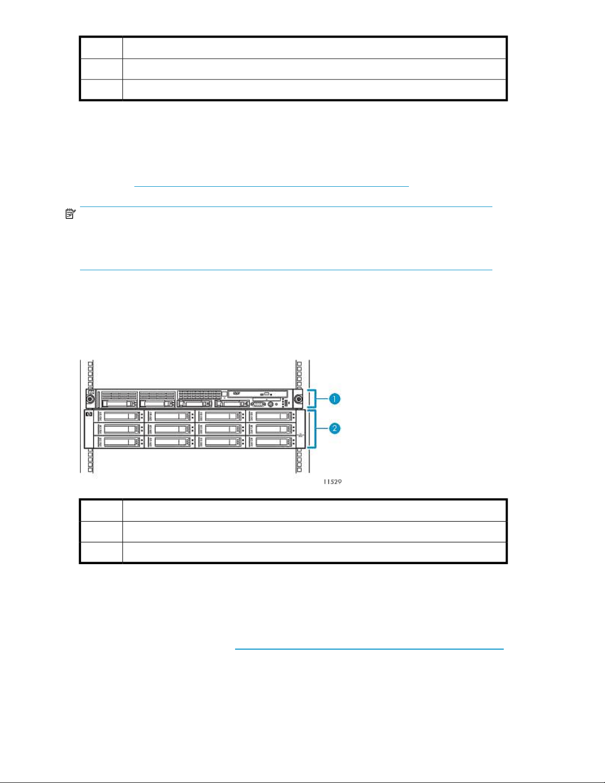
An optional second MSA20 disk array can be added to a VLS6100 by purchasing a VLS capacity
bundle. A VLS capacity bundle includes a disk array with twelve SATA disks and a capacity license
for the additional disk array.
Adding a second disk array doubles the VLS6100 storage capacity. Adding a second disk array also
increases the performance. See the HP StorageWorks 6000 virtual library system Quickspec on the
HP web site (http://h18006.www1.hp.com/products/storageworks/6000vls) for performance data.
NOTE:
You can also re-use an existing MSA20 disk array with twelve blank SATA disks of the same, supported
type (all 250 GB, all 500 GB, or all 750 GB disks) and the latest MSA20 firmware. Purchase a
capacity license for the additional disk array (two licenses for each 750 GB disk) separately.
VLS6200–series
A VLS6200–series consists of a VLS6200–series node (head unit) and one Modular Smart Array 20
(MSA20) disk array. The node includes a single processor, two 4 GB Fibre Channel host ports, and
four VHDCI connectors. The disk array contains twelve SATA disks.
DescriptionItem
Node1
Disk array 02
DescriptionItem
Node1
Disk array 02
Up to three disk arrays can be added to a VLS6200 by purchasing up to three VLS capacity bundles.
A VLS capacity bundle includes a disk array with twelve SATA disks and a capacity license for the
additional disk array.
Adding disk arrays expands the VLS6200 storage capacity as shown in VLS6200-series capacity.
Adding disk arrays also increases the performance. See the HP StorageWorks 6000 virtual library
syst em Quic ks pec on the HP web site (http://h18006.www1.hp.com/products/storageworks/6000vls)
for performance data.
Introduction20
Page 21
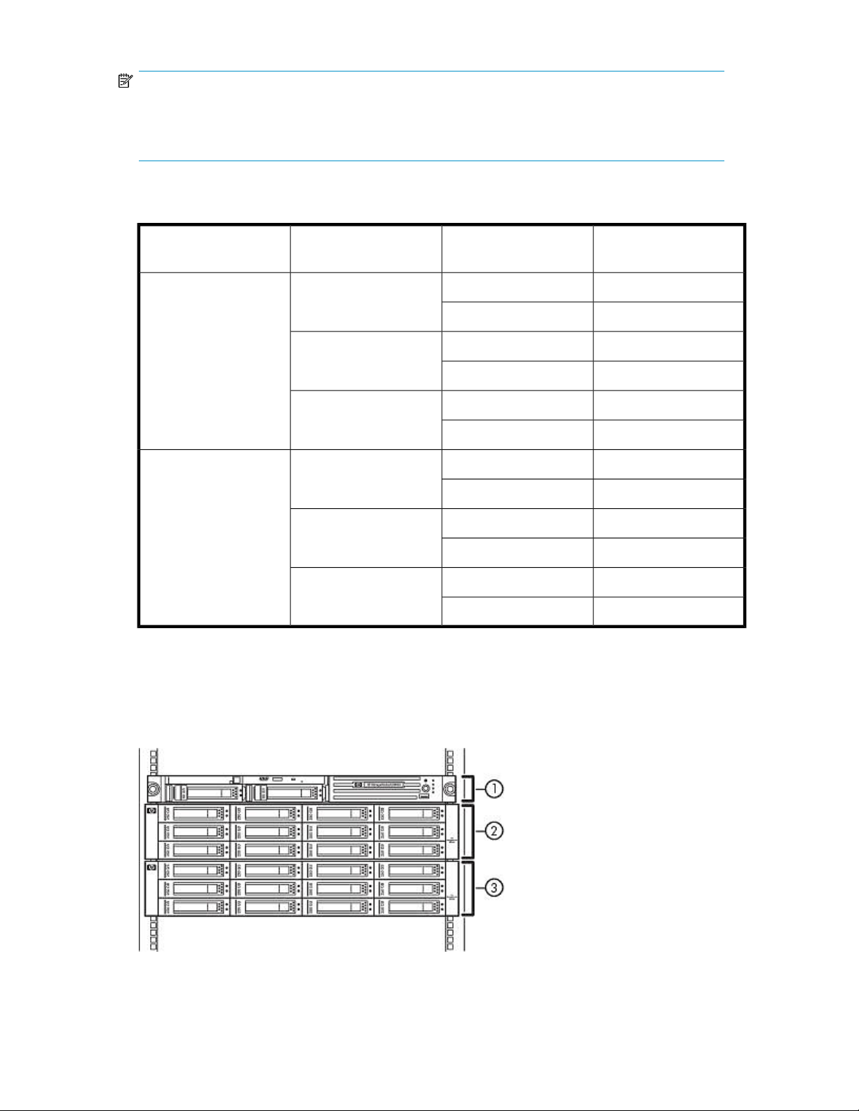
NOTE:
You can also re-use an existing MSA20 disk array with twelve blank SATA disks of the same, supported
type (all 250 GB, all 500 GB, or all 750 GB disks) and the latest MSA20 firmware. Purchase a
capacity license for the additional disk array separately.
Table 1 VLS6200–series capacity (based on RAID5 configuration; capacity is lower in RAID6
configuration)
VLS6218
(all 500 GB disks)
VLS6227
(all 750 GB disks)
Disk arraysModel
2
3
4
2
3
4
Data compression (2:1)
enabled
Capacity
8.8 TBNo
17.6 TBYes
13.2 TBNo
26.4 TBYes
17.6 TBNo
35.2 TBYes
13.2 TBNo
26.4 TBYes
19.8 TBNo
39.6 TBYes
26.4 TBNo
52.8 TBYes
VLS6500–series
A VLS6500 consists of a VLS6500 node (head unit) and two MSA20 disk arrays. The node contains
dual processors, four 2 GB Fibre Channel host ports, and four VHDCI connectors. Each disk array
contains twelve SATA disks.
HP StorageWorks 6000–series Virtual Library System User Guide 21
Page 22
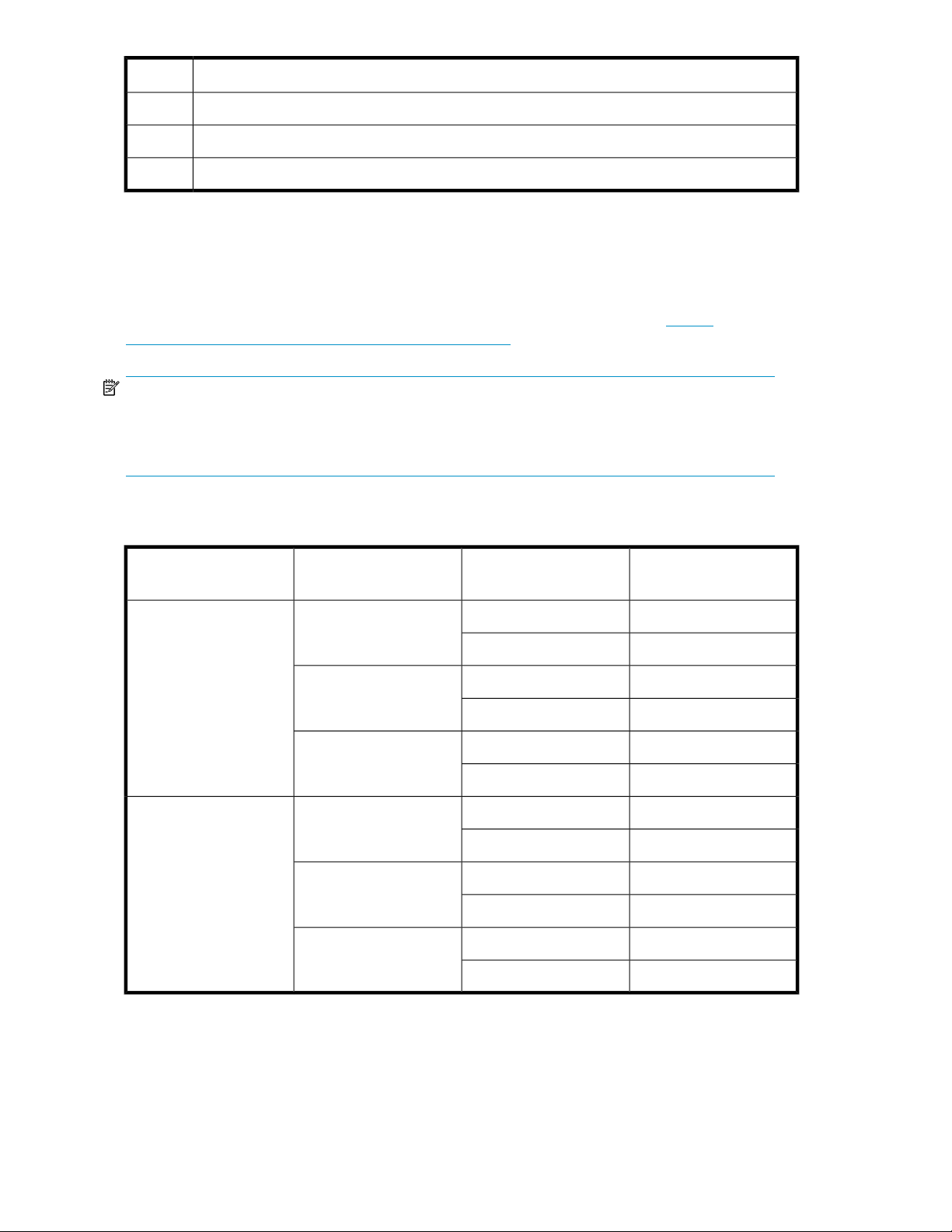
DescriptionItem
Node1
Disk array 02
Disk array 13
An optional third and fourth disk array can be added to a VLS6500 by purchasing one or two VLS
capacity bundles. A VLS capacity bundle includes a disk array with twelve SATA disks and a capacity
license for the additional disk array.
Adding a third and fourth disk array expands the VLS6500 storage capacity as shown in
VLS6500-series capacity. Adding a third and fourth disk array also increases the performance. See
the HP StorageWorks 6000 virtual library system Quickspec on the HP web site (http://
h18006.www1.hp.com/products/storageworks/6000vls) for performance data.
NOTE:
You can also re-use an existing MSA20 disk array with twelve blank SATA disks of the same, supported
type (all 250 GB, all 500 GB, or all 750 GB disks) and the latest MSA20 firmware. Purchase a
capacity license for the additional disk array separately.
Table 2 VLS6500–series capacity (based on RAID5 configuration; capacity is lower in RAID6
configuration)
VLS6510
(all 250 GB disks)
VLS6518
(all 500 GB disks)
Disk arraysModel
2
3
4
2
3
4
Data compression (2:1)
enabled
Capacity
5 TBNo
10 TBYes
7.5 TBNo
15 TBYes
10 TBNo
20 TBYes
8.8 TBNo
17.6 TBYes
13.2 TBNo
26.4 TBYes
17.6 TBNo
35.2 TBYes
Introduction22
Page 23
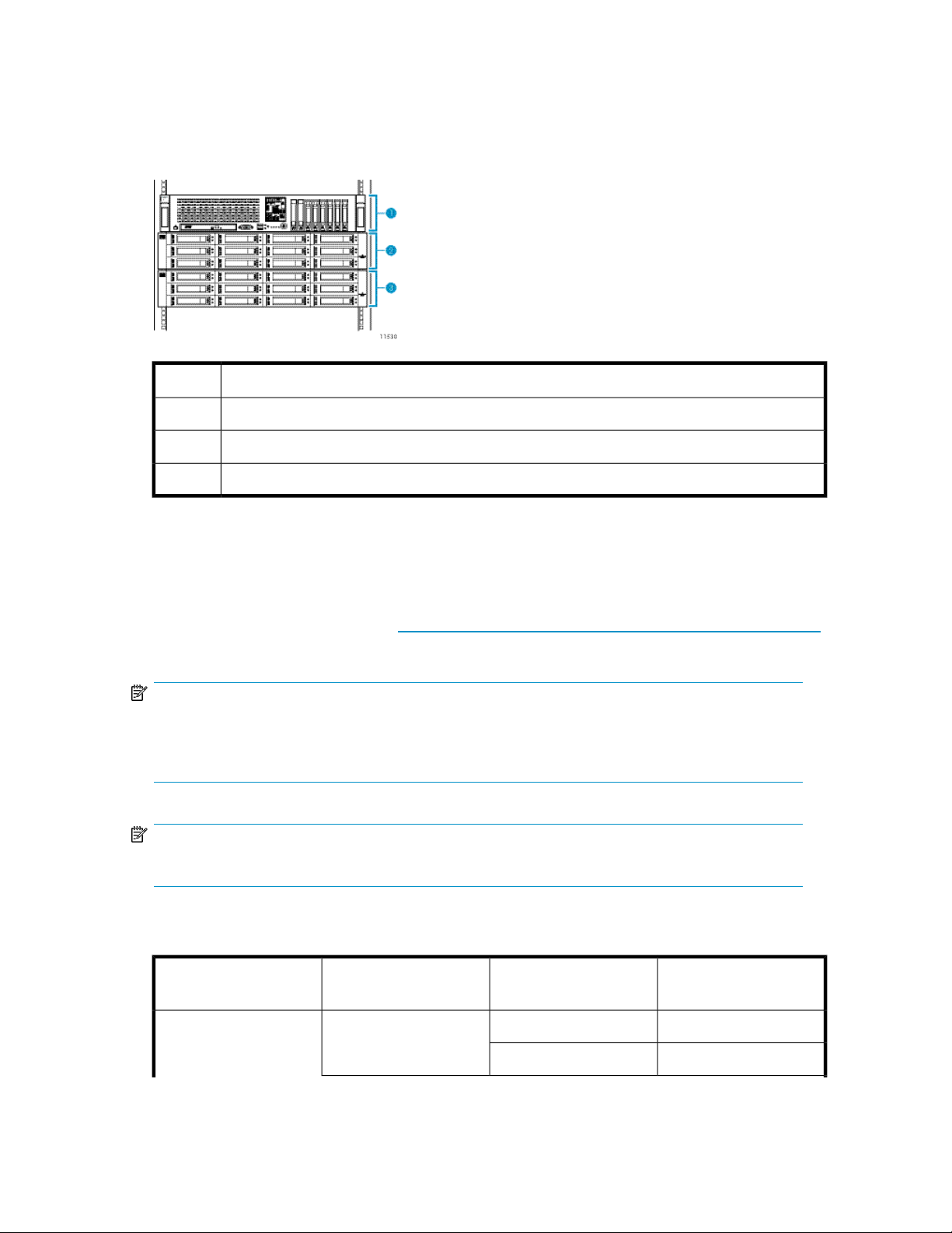
VLS6600–series
A VLS6600–series consists of a VLS6600–series node (head unit) and two Modular Smart Array 20
(MSA20) disk arrays. The node includes dual processors, four 4 GB Fibre Channel host ports, and
eight VHDCI connectors. The disk array contains twelve SATA disks.
Up to six disk arrays can be added to a VLS6600 by purchasing up to six VLS capacity bundles. A
VLS capacity bundle includes a disk array with twelve SATA disks and a capacity license for the
additional disk array.
DescriptionItem
Node1
Disk array 02
Disk array 13
Adding disk arrays expands the VLS6600 storage capacity as shown in VLS6600-series capacity.
Adding disk arrays also increases the performance. See the HP StorageWorks 6000 virtual library
syst em Quic ks pec on the HP web site (http://h18006.www1.hp.com/products/storageworks/6000vls)
for performance data.
NOTE:
You can also re-use an existing MSA20 disk array with twelve blank SATA disks of the same, supported
type (all 250 GB, all 500 GB, or all 750 GB disks) and the latest MSA20 firmware. Purchase a
capacity license for the additional disk array separately.
NOTE:
Hardware compression is automatically enabled upon installation of a VLS6600–series system.
Table 3 VLS6600–series capacity (based on RAID5 configuration; capacity is lower in RAID6
configuration)
VLS6636
(all 500 GB disks)
Disk arraysModel
3
Data compression (2:1)
enabled
Capacity
13.2 TBYes
26.4 TBYes
HP StorageWorks 6000–series Virtual Library System User Guide 23
Page 24

Disk arraysModel
4
5
6
7
8
3
4
Data compression (2:1)
enabled
Capacity
17.6 TBYes
35.2 TBYes
22 TBYes
44 TBYes
26.4 TBYes
52.8 TBYes
30.8 TBYes
61.6 TBYes
35.2 TBYes
70.4 TBYes
19.8 TBYes
39.6 TBYes
26.4 TBYes
52.8 TBYes
VLS6653
(all 750 GB disks)
VLS6800–series
A VLS6800–series consists of a VLS6800–series node (head unit) and four MSA20 disk arrays. The
node contains dual processors, four 2 GB Fibre Channel host ports, and sixteen VHDCI connectors.
Each disk array contains twelve SATA disks.
33 TBYes
5
66 TBYes
39.6 TBYes
6
79.2 TBYes
46.2 TBYes
7
92.4 TBYes
52.8 TBYes
8
105.6 TBYes
Introduction24
Page 25
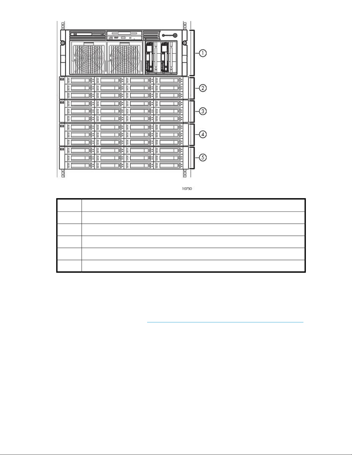
DescriptionItem
Node1
Disk array 02
Disk array 13
Disk array 24
Disk array 35
Up to twelve disk arrays can be added to a VLS6800 by purchasing up to twelve VLS capacity
bundles. A VLS capacity bundle includes a disk array with twelve SATA disks and a capacity license
for the additional disk array.
Adding disk arrays increases the VLS6800 storage capacity as shown in VLS6800-series capacity.
Adding disk arrays also increases the performance. See the HP StorageWorks 6000 virtual library
syst em Quic ks pec on the HP web site (http://h18006.www1.hp.com/products/storageworks/6000vls)
for performance data.
HP StorageWorks 6000–series Virtual Library System User Guide 25
Page 26

NOTE:
You can also re-use an existing MSA20 disk array with twelve blank SATA disks of the same, supported
type (all 250 GB, all 500 GB, or all 750 GB disks) and the latest MSA20 firmware. Purchase a
capacity license for the additional disk array separately.
Table 4 VLS6800–series capacity (based on RAID5 configuration; capacity is lower in RAID6
configuration)
VLS6840
(all 250 GB disks)
Disk arraysModel
4
5
6
7
8
9
10
Data compression (2:1)
enabled
Capacity
10 TBNo
20 TBYes
12.5 TBNo
25 TBYes
15 TBNo
30 TBYes
17.5 TBNo
35 TBYes
20 TBNo
40 TBYes
22.5 TBNo
45 TBYes
25 TBNo
50 TBYes
27.5 TBNo
11
55 TBYes
30 TBNo
12
60 TBYes
32.5 TBNo
13
65 TBYes
35 TBNo
14
70 TBYes
37.5 TBNo
15
75 TBYes
Introduction26
Page 27

Disk arraysModel
16
4
5
6
7
8
9
Data compression (2:1)
enabled
Capacity
40 TBNo
80 TBYes
17.6 TBNo
35.2 TBYes
22 TBNo
44 TBYes
26.4 TBNo
52.8 TBYes
30.8 TBNo
61.6 TBYes
35.2 TBNo
70.4 TBYes
39.6 TBNo
79.2 TBYes
VLS6870
(all 500 GB disks)
44 TBNo
10
88 TBYes
48.4 TBNo
11
96.8 TBYes
52.8 TBNo
12
105.6 TBYes
57.2 TBNo
13
114.4 TBYes
61.6 TBNo
14
123.2 TBYes
66 TBNo
15
132 TBYes
70.4 TBNo
16
140.8 TBYes
HP StorageWorks 6000–series Virtual Library System User Guide 27
Page 28

Introduction28
Page 29

2 Hardware Installation
This section details the steps to install the VLS hardware from installation preparation to final cabling.
Preparing for the Installation
Tools for Installation
• Two people
• #1 and #2 Phillips screwdriver
• Box cutting knife
CAUTION:
Do not use any power tools. They could strip or damage connections.
Taking ESD Precautions
To prevent damaging the system, be aware of the precautions you need to follow when setting up
the system or handling parts. A discharge of static electricity from a finger or other conductor may
damage system boards or other static-sensitive devices. This type of damage may reduce the life
expectancy of the device.
To prevent electrostatic damage:
• Avoid hand contact by transporting and storing products in static-safe containers.
• Keep electrostatic-sensitive parts in their containers until they arrive at static-free workstations.
• Place parts on a grounded surface before removing them from their containers.
• Avoid touching pins, leads, or circuitry.
• Always be properly grounded when touching a static-sensitive component or assembly.
Grounding Methods to Prevent Electrostatic Discharge
Several methods are used for grounding. Use one or more of the following methods when handling
or installing electrostatic-sensitive parts:
• Use a wrist strap connected by a ground cord to a grounded workstation or computer chassis.
Wrist straps are flexible straps with a minimum of 1 megaohm ±10 percent resistance in the
ground cords. To provide proper ground, wear the strap snug against the skin.
• Use heel straps, toe straps, or boot straps at standing workstations.
Wear the straps on both feet when standing on conductive floors or dissipating floor mats.
• Use conductive field service tools.
• Use a portable field service kit with a folding static-dissipating work mat.
HP StorageWorks 6000–series Virtual Library System User Guide 29
Page 30

If you do not have any of the suggested equipment for proper grounding, have an authorized reseller
install the part.
For more information on static electricity or assistance with product installation, contact your authorized
reseller.
Unpacking
Place the shipping carton as close to the installation site as possible. Before unpacking the VLS, inspect
the shipping carton for damage that may have occurred during shipment. If you detect any damage,
notify the carrier and HP before unpacking the unit.
Removing the Packing Materials
To unpack the VLS:
1. Open the top of the shipping cartons.
2. Carefully lift the units out of the boxes and remove the packing materials.
3. Place the units on a stable work surface.
NOTE:
Inspect the units for any damage that may have occurred during shipment. If damage is
detected, contact your authorized service representative.
4. Remove the accessory kits and documentation from the shipping cartons. Set them aside for later
use.
5. Place shipping materials back into the shipping cartons.
6. Set the shipping cartons aside for later use.
Rack Planning Resources
The rack resource kit ships with all HP or Compaq branded 9000, 10000, and H9 series racks. A
summary of the content of each resource follows:
• Custom Builder is a web-based service for configuring one or many racks. Rack configurations
can be created using:
• A simple, guided interface
• Build-it-yourself model
• The Installing Rack Products video provides a visual overview of operations required for configuring
a rack with rack-mountable components. It also provides the following important configuration
steps:
• Planning the site
• Installing rack servers and rack options
• Cabling servers in a rack
• Coupling multiple racks
Hardware Installation30
Page 31

• The Rack Products Documentation CD enables you to view, search, and print documentation for
HP and Compaq branded racks and rack options. It also helps you set up and optimize a rack in
a manner that best fits your environment.
Rack Requirements
HP supports the HP System E racks and the HP 10000 Series racks for use with VLS systems. Other
racks might also be suitable, but have not been tested with the VLS.
Rack Warnings
WARNING!
To reduce the risk of personal injury or damage to the equipment, be sure that:
• The leveling jacks are extended to the floor.
• The full weight of the rack rests on the leveling jacks.
• The stabilizing feet are attached to the rack if it is a single-rack installation.
• The racks are coupled together in multiple-rack installations.
• Only one component is extended at a time. A rack may become unstable if more than one com-
ponent is extended for any reason.
WARNING!
To reduce the risk of personal injury or equipment damage when unloading a rack:
• At least two people are needed to safely unload a rack from a pallet. An empty 42U rack can
weigh as much as 115 kg (253 lb), can stand more than 2.1 m (7 ft) tall, and may become unstable
when being moved on its casters.
• Never stand in front of a rack when it is rolling down the ramp from the pallet. Always handle a
rack from both sides.
Identifying the VLS Shipping Carton Contents
Unpack the VLS shipping cartons and locate the materials and documentation necessary for installing
the VLS. All the rack mounting hardware and documentation necessary for installing a VLS node into
a rack is included in the node shipping carton. All the rack mounting hardware and documentation
necessary for installing a VLS disk array into a rack is included in the disk array shipping carton.
HP StorageWorks 6000–series Virtual Library System User Guide 31
Page 32

VLS6100 and VLS6500 System Shipping Carton
DescriptionItem
Node1
Node power cord2
Serial cable3
1U rack mounting hardware kit and documentation4
Printed VLS node installation poster5
Documentation CD and VLS Quick Restore CD6
Hardware Installation32
Page 33

VLS6200 System Shipping Carton
DescriptionItem
Node1
Node power cords (2)2
Serial cable3
1U rack mounting hardware kit and documentation4
Printed VLS6200 node installation poster5
Documentation CD and VLS6200 Quick Restore CD6
Loopback plugs7
VLS6600 System Shipping Carton
HP StorageWorks 6000–series Virtual Library System User Guide 33
Page 34

DescriptionItem
Node1
Node power cords (2)2
Serial cable3
1U rack mounting hardware kit and documentation4
Printed VLS6600 node installation poster5
Documentation CD and VLS6600 Quick Restore CD6
Loopback plugs7
VLS6800 System Shipping Carton
DescriptionItem
Node1
Node power cords (2)2
Serial cable3
Rack mounting hardware4
Printed VLS node installation poster5
Documentation CD and VLS Quick Restore CD6
Hardware Installation34
Page 35

Disk Array Shipping Carton
DescriptionItem
MSA20 disk array1
SCSI cable2
Printed VLS disk array installation poster3
Disk array power cords (2)4
2U rack mounting hardware kit and documentation5
Installing the Disk Arrays into a Rack
This section describes how to install the MSA20 disk array.
WARNING!
Do not use the handles on the disk array power supply units to lift or hold the disk array. These handles
are designed only for holding the power supply units or removing them from the disk array, not for
supporting the weight of the disk array.
Rack Mounting Requirements
Each disk array requires a vertical rack space of 2U (equivalent to 89 mm, or 3.5 inches).
HP recommends that you mount the disk arrays in the order shown in Figure 1, Figure 2, or VLS6600
and VLS6800 disk array rack mounting order, depending on model.
HP StorageWorks 6000–series Virtual Library System User Guide 35
Page 36

Figure 1 VLS6100, VLS6200, and VLS6500 disk array rack mounting order
.
DescriptionItem
Disk array 31
Disk array 22
Node3
Disk array 04
Disk array 15
Hardware Installation36
Page 37

Figure 2 VLS6600 disk array rack mounting order
.
DescriptionItem
Disk array 71
Disk array 62
Disk array 53
Disk array 44
Node5
Disk array 06
Disk array 17
Disk array 28
Disk array 39
HP StorageWorks 6000–series Virtual Library System User Guide 37
Page 38

Figure 3 VLS6800 disk array rack mounting order
.
DescriptionItem
Disk array 151
Disk array 142
Disk array 133
Disk array 124
Disk array 115
Disk array 106
Disk array 97
Disk array 88
Hardware Installation38
Page 39

DescriptionItem
Node9
Disk array 010
Disk array 111
Disk array 212
Disk array 313
Disk array 414
Disk array 515
Disk array 616
Disk array 717
Mounting a Disk Array into a Rack
WARNING!
The disk array weighs 24.6 kg (54.3 lb) full. At least two people are required to lift,
move, and install the disk array.
HP StorageWorks 6000–series Virtual Library System User Guide 39
Page 40

1. Use the 2U rack mounting template as a guide to indicate where on the rack the rails for the disk
array are to be mounted.
a. At the front of the rack, with the front of the template facing you, align the lower edge of
the template with the bottom of the rack (or the top of the previous rack component). Be sure
that the lower edge of the template is level.
b. Push the template tabs into the holes in the rack uprights to hold the template in place.
Figure 4 Positioning the rack mounting template
.
c. Use a permanent marker pen to indicate the holes in the rack uprights into which the
scissor-like locking latches are to be inserted, as specified by the template.
d. Repeat these steps to mark the back of the rack, using the information on the back of the
template as a guide to the required location of the locking latches in this case.
WARNING!
The pins in the rails are load-bearing. Do not remove the pins except to replace them with
the pins for round-hole racks.
2. If the holes in the rack uprights are round instead of square, remove the standard pins from the
rails and replace them with the round-hole pins provided in the rack mounting hardware kit.
3. Identify the left (L) and right (R) rack rails by markings stamped into the rails.
Hardware Installation40
Page 41

4. Slide the front end of the right rack rail toward the inside front of the rack until the locking latch
engages with the marked hole in the front rack upright.
Figure 5 Engaging the rack rail with the marked hole in the front of the rack
.
5. Extend the back end of the rail toward the inside rear of the rack until the locking latch engages
with the marked hole in the rear rack upright.
Figure 6 Engaging the rack rail with the marked hole in the rear of the rack
.
HP StorageWorks 6000–series Virtual Library System User Guide 41
Page 42

6. Loosen the locknut on the shipping bracket, and move the bracket to the rearmost position on the
rail.
Figure 7 Loosening the locknut on the shipping bracket
.
7. Repeat steps 4 through 6 for the left rack rail.
8. Align the disk array with the rails, and slide it into the rack.
Figure 8 Aligning the disk array with the rails
.
Hardware Installation42
Page 43

9. Remove the mounting bracket covers, and tighten the thumbscrews to secure the disk array to
the rack.
Figure 9 Removing the mounting bracket covers
.
10. Replace the mounting bracket covers.
11. If you intend to move the rack while the disk array is installed, adjust the shipping brackets on
each rail to secure the disk array to the rack.
a. Loosen the shipping bracket locknut.
b. Slide the bracket forward until it engages with the disk array chassis.
c. Tighten the locknut.
d. Repeat this procedure for the other rail.
Figure 10 Sliding the bracket forward to engage with the disk array
.
HP StorageWorks 6000–series Virtual Library System User Guide 43
Page 44

Installing the VLS6100 and VLS6500 Nodes into a Rack
NOTE:
Install components starting with the first available slot at bottom of the rack and working toward the
top of the rack. Starting at the bottom distributes the weight correctly in the cabinet.
NOTE:
If you are installing the node into a telco rack, order the appropriate option kit at the RackSolutions.com
web site: http://www.racksolutions.com/hp. Follow the instructions on the web site to install the rack
brackets.
To install a node into the rack involves three main tasks:
• Install Rails in the Rack
• Attach Rails to the Node
• Install Appliance in Rack
Install Rails in the Rack
1. Locate the appropriate rail kit—part number 360332–003.
2. Install the two slide rails to the sides of the rack.
a. Adjust the side rail assemblies to the approximate rack depth.
b. At one side of the rack, align the rail holes with the holes in the rack and secure with the
provided mounting hardware using a #2 Phillips screwdriver.
Figure 11 Install rails
.
c. Repeat these tasks for the rail on the other side of the rack.
Hardware Installation44
Page 45

3. Remove the inner slide rails from the outer slide rails. To do so, extend the inner slide rails from
the front of the rack until they lock in place. Then press the inner rail release latch (see Figure
12) and pull the inner slide rails straight out.
Figure 12 Remove slides from rails
.
Attach Rails to the Node
To attach the rails to the node:
1. Align the rail with the node so that the word “FRONT” on the rail is seen right-side-up and at the
front of the node.
Figure 13 Attaching rails to the node
.
2. Align the holes in the rail with the round tabs on the side of the node.
3. Put the rail onto the node with the tabs extending into the holes on the side of the rail, then slide
the rail toward the front of the node until the tabs are locked into the rail.
4. Perform these steps again to Install the other rail on the other side of the node.
Install Appliance in Rack
1. Align the rails on the node with the rails in the rack.
2. Slide the node fully into the rack.
The rails on the node will lock into the rails on the rack.
HP StorageWorks 6000–series Virtual Library System User Guide 45
Page 46

3. With the node fully seated in the rack, tighten the thumbscrews just until the node bezel is secured
to the rack.
Installing the VLS6600 Node into a Rack
NOTE:
If you are installing the node into a telco rack, order the appropriate option kit at the RackSolutions.com
web site: http://www.racksolutions.com/hp. Follow the instructions on the web site to install the rack
brackets.
NOTE:
Allow enough rack space above and/or below the node to mount the disk arrays. A disk array
requires a vertical rack space of 2U (equivalent to 89 mm, or 3.5 inches).
To install a VLS6600 node into the rack involves three main tasks:
1. Install Rails in the Rack
2. Attach Rails to the VLS6600 Node (appliance)
3. Install Appliance in the Rack
Install Rails in the Rack
To install the rails in the rack:
1. Locate the appropriate rail kit—part number 365517-B21.
Hardware Installation46
Page 47

2. Install the two slide rails in the rack.
a. Locate the slide rail with the words REAR LEFT and align it with the rear of the left side of
the rack as you face the front of the rack.
b. Adjust the slide rail assemblies to the approximate rack depth.
c. From the outside rear of the rack, insert the screws of the slide rail rear bracket into the
appropriate holes in the rack and pull the rail forward until the rear bracket of the rail snaps
into place.
Figure 14 Attaching the rear bracket of the slide rail to the rack
.
d. From the outside front of the rack on the left rail, insert the screws of the slide rail front bracket
into the appropriate holes in the rack and push the rail back until the front bracket of the
rail snaps into place.
e. Repeat these steps with the right bracket on the right side of the rack.
Attach Rails to the VLS6600 Node (appliance)
To attach the rails to the appliance:
1. Align one of the rails with the left side of the node (as you face the front of the node) so that the
word “FRONT” on the rail is seen right-side-up and at the front of the node.
Figure 15 Attaching rails to the VLS6600 node
.
2. Align the holes in the rail with the round tabs on the side of the node.
3. Put the rail onto the node with the tabs extending into the holes on the side of the rail, then slide
the rail toward the front of the node until the tabs are locked into the rail.
HP StorageWorks 6000–series Virtual Library System User Guide 47
Page 48

4. On the other side of the node, align the remaining rail so that the word “FRONT” on the rail is
seen at the front of the node. It will be printed upside-down.
5. Align the holes in the rail with the round tabs on the side of the node.
6. Put the rail onto the node with the tabs extending into the holes on the side of the rail, then slide
the rail toward the front of the node until the tabs are locked into the rail.
Install Appliance in the Rack
To install the appliance into the rack:
1. Align the rails on the appliance with the rails in the rack.
2. Slide the appliance fully into the rack.
The rails on the appliance will lock into the rails on the rack. When fully seated against the rack,
the appliance will also lock into place.
Installing the VLS6800 Node into a Rack
Follow the steps in this section if you are installing the VLS6800 node into a rack with square holes.
If you are installing the node into a rack with round holes, order the appropriate rack installation
option kit, and then refer to the installation instructions that ship with the option kit for more information.
If you are installing the VLS6800 node into a telco rack, order the appropriate option kit at the
RackSolutions.com web site (http://www.racksolutions.com/hp). Follow the node-specific instructions
on the web site to install the rack brackets. After installing the brackets, follow the steps in this section.
WARNING!
When installing the node in a telco rack, be sure that the rack frame is adequately secured to the top
and bottom of the building structure.
NOTE:
Allow enough rack space above and/or below the node to mount the disk arrays. A disk array
requires a vertical rack space of 2U (equivalent to 89 mm, or 3.5 inches).
Plan to mount up to four disk arrays below the node and after that up to four more disk arrays above
the node as shown in VLS6600 and VLS6800 disk array rack mounting order.
To install a VLS6800 node into the rack involves three main tasks:
• Install Rails in the Rack
• Install Appliance in Rack
Hardware Installation48
Page 49

Install Rails in the Rack
1. Mark the rack.
WARNING!
Always plan the rack installation so that the heaviest item is on the bottom of the rack. Install
the heaviest item first, and continue to populate the rack from the bottom to the top.
Figure 16 Measuring with the template
.
2. From the front of the rack, identify the rear rack holes on the inside of the vertical rack that you
marked with the template.
3. Pull the rail compression lever toward you.
Figure 17 Pulling the rail compression lever
.
HP StorageWorks 6000–series Virtual Library System User Guide 49
Page 50

4. Insert the two rail tabs from the end of the rack rail assembly into the marked holes on the inside
of the rear of the rack.
Figure 18 Inserting the rail tabs on the rear of the rack
.
5. Adjust the rack rail depth by sliding it forward.
6. Insert the two rail tabs from the rack rail assembly into the marked holes on the inside of the front
of the rack.
Figure 19 Inserting the rail tabs on the front of the rack
.
7. Release the rail compression lever to seat the tabs in the rack post.
8. Repeat steps 3 through 7 for the other rail.
Hardware Installation50
Page 51

Install Appliance in Rack
1. Attach the node rails to the node.
Figure 20 Attaching a node rail to the node
.
WARNING!
The node is very heavy, 44.5 kg (98 lb) full. To reduce the risk of personal injury or damage
to the equipment:
• Remove the hot-plug power supplies to reduce the weight of the node before lifting it.
Do not remove any other hardware.
• Observe local occupational health and safety requirements and guidelines for material
handling.
• At least two people are required to lift and rack mount the node.
2. Remove the node power supplies. See Power Supply.
3. Pull the inner slide rail forward from each rack rail assembly until it locks into place.
HP StorageWorks 6000–series Virtual Library System User Guide 51
Page 52

4. Slide the inner bearing brace forward until it stops.
Figure 21 Locking the inner slide rails into place
.
CAUTION:
Keep the node parallel to the floor when sliding the node rails into the standard rack rails.
Tilting the node up or down can result in damage to the rails.
5. Lift the node using the four lift handles on the sides of the node.
6. Align the node, and carefully insert the node rail into the inner slide rail until the rail-release
levers engage.
Figure 22 Loading the node onto the rack rails
.
Hardware Installation52
Page 53

7. Reach around the front of the node to press the rail-release levers at the front of both node rails,
and continue to slide the node into the rack.
Figure 23 Sliding the node to the rear of the rack
.
8. Tighten the thumbscrews to secure the node to the rack.
Figure 24 Tightening the thumbscrews
.
9. Reinstall the power supplies.
Installing the VLS6200 Node into a Rack
NOTE:
If you are installing the node into a telco rack, order the appropriate option kit at the RackSolutions.com
web site: http://www.racksolutions.com/hp. Follow the instructions on the web site to install the rack
brackets.
HP StorageWorks 6000–series Virtual Library System User Guide 53
Page 54

Install the node in the rack as follows:
1. Locate the rail kit — part number 360332–003.
Install the two outer slide rails to the rack. The outer rails are marked “FRONT” and “REAR.”
On both sides of the rack, align the rail holes with the holes in the rack and secure.
2. Attach the inner rails to the sides of the node.
Align the holes in the rail with the round tabs on the side of the node.
NOTE:
The inner rails are identical.
The word “FRONT” should face away from the node, but will appear updside-down on one
side.
3. Align the rails on the node with the rails in the rack, and slide the node fully into the rack.
4. Tighten the thumbscrews.
Hardware Installation54
Page 55

Installing VLS6100, VLS6200, VLS6500, and VLS6600 Cables
1. Connect Fibre Channel cables from your SAN media server or from your physical tape libraries
(for automigration) to the node Fibre Channel host ports, starting with Fibre Channel host port 0
and working towards Fibre Channel host port 3 (Figure 25, Figure 26, and Figure 27).
NOTE:
For Automigration, you will be asked to select the number of Fibre Channel ports to reserve
for Automigration. The software will then reserve that number of ports, beginning with port
3, then port 2, etc. so that the left-most ports as you face the back of the library are used
to connect to physical libraries, either directly or through an Fibre Channel switch.
a. VLS6100 and VLS6500
Figure 25 VLS6100 and VLS6500 — Connecting SAN and LAN cabling to the node
.
DescriptionItem
FC host port 01
FC host port 12
FC host port 23
FC host port 34
10/100/1000 NIC 1 connector5
b. VLS6200
Figure 26 VLS6200 — Connecting SAN and LAN cabling to the node
.
HP StorageWorks 6000–series Virtual Library System User Guide 55
Page 56

DescriptionItem
FC host port 01
FC host port 12
NIC 1 connector3
c. VLS6600
Figure 27 VLS6600 — Connecting SAN and LAN cabling to the node
.
DescriptionItem
FC host port 01
FC host port 12
FC host port 23
FC host port 34
NIC 1 connector5
2. Install a Fibre Channel loopback plug in any unused Fibre Channel host ports. Loopback plugs
are included in the server accessory kit.
NOTE:
Unused Fibre Channel ports without loopback plugs cause connection failures and associated
failure notifications.
3. Connect a standard Ethernet (CAT-5) cable from your local IP network (LAN) to the 10/100/1000
NIC 1 (RJ-45) connector (Figure 25, Figure 26, and Figure 27).
WARNING!
To reduce the risk of electric shock, fire, or damage to the equipment, do not
plug telephone or telecommunications connectors into RJ-45 (NIC) connectors.
Hardware Installation56
Page 57

4. Connect the VHDCI connector on each disk array to the appropriate VHDCI connector on the
node (Figure 28, Figure 29, and Figure 30).
Figure 28 VLS6100 and VLS6500 — Connecting the VHDCI connectors to disk arrays
.
DescriptionItem
VHDCI connector A1, connect to Disk array 01
VHDCI connector A2, connect to Disk array 12
3
4
1
Not applicable to the VLS6100.
VHDCI connector B1, connect to Disk array 2
VHDCI connector B2, connect to Disk array 3
1
1
HP StorageWorks 6000–series Virtual Library System User Guide 57
Page 58

Figure 29 VLS6200 — Connecting the VHDCI connectors to disk arrays
.
DescriptionItem
VHDCI connector A1, connect to Disk array 01
VHDCI connector A2, connect to Disk array 12
VHDCI connector B1, connect to Disk array 23
VHDCI connector B2, connect to Disk array 34
Figure 30 VLS6600 — Connecting the VHDCI connectors to disk arrays
.
DescriptionItem
VHDCI connector slot 4, A1, connect to disk array enclosure 01
VHDCI connector slot 4, A2, connect to disk array enclosure 12
VHDCI connector slot 4, B1, connect to disk array enclosure 23
VHDCI connector slot 4, B2, connect to disk array enclosure 34
VHDCI connector slot 5, A1, connect to disk array enclosure 45
VHDCI connector slot 5, A2, connect to disk array enclosure 56
VHDCI connector slot 5, B1, connect to disk array enclosure 67
VHDCI connector slot 5, B2, connect to disk array enclosure 78
Hardware Installation58
Page 59

WARNING!
To reduce the risk of electric shock or damage to the equipment:
• Do not disable the power cord grounding plug. The grounding plug is an important
safety feature.
• Plug the power cord into a grounded (earthed) electrical outlet that is easily accessible
at all times.
• Unplug the power cord from the power supply to disconnect power to the equipment.
• Do not route the power cord where it can be walked on or pinched by items placed
against it. Pay particular attention to the plug, electrical outlet, and the point where the
cord extends from the node.
5. Connect the node power supplies' AC power connectors to two separate AC power sources
using the power cables provided (Figure 31).
Figure 31 Connecting the node power supplies to an AC power source
.
6. Use the strain relief clip from the node hardware kit to secure the power cord (Figure 32).
Figure 32 Securing the power cord with the strain relief clip
.
7. Connect the disk array power supply AC power connectors on the left-side to one AC power
source using the power cables provided. Then, connect the disk array power supply AC power
connectors on the right-side to a second AC power source using the power cables provided
(Figure 33).
Figure 33 Connecting the disk array power supplies to an AC power source
.
HP StorageWorks 6000–series Virtual Library System User Guide 59
Page 60

Installation is complete. You may now power up the disk array(s) and then the node as described in
Operation.
Installing VLS6800 Cables
1. Connect Fibre Channel cables from your SAN media server to the node Fibre Channel host ports,
starting with Fibre Channel host port 0 and working towards Fibre Channel host port 3 (Figure
34).
Leave the Fibre Channel loopback plug in any unused Fibre Channel host ports. This will prevent
you from receiving Fibre Channel notification alerts, which are generated by the VLS when no
signal is detected at a Fibre Channel host port.
Figure 34 Connecting SAN and LAN cabling to the node
.
DescriptionItem
10/100/1000 NIC 1 connector1
FC host port 02
FC host port 13
FC host port 24
FC host port 35
2. Connect a standard Ethernet (CAT-5) cable from your local IP network (LAN) to the 10/100/1000
NIC 1 (RJ-45) connector (Figure 34).
WARNING!
To reduce the risk of electric shock, fire, or damage to the equipment, do not plug telephone
or telecommunications connectors into RJ-45 (NIC) connectors.
Hardware Installation60
Page 61

3. Connect the VHDCI connector on each disk array to the appropriate VHDCI connector on the
node using the SCSI cables provided (Figure 35).
Figure 35 Connecting the VHDCI connector on each disk array to the appropriate VHDCI connector
on the node
.
DescriptionItem
VHDCI connector slot 8, A1, connect to Disk array 01
VHDCI connector slot 8, A2, connect to Disk array 12
VHDCI connector slot 8, B1, connect to Disk array 23
HP StorageWorks 6000–series Virtual Library System User Guide 61
Page 62

DescriptionItem
VHDCI connector slot 8, B2, connect to Disk array 34
VHDCI connector slot 7, A1, connect to Disk array 45
VHDCI connector slot 7, A2, connect to Disk array 56
VHDCI connector slot 7, B1, connect to Disk array 67
VHDCI connector slot 7, B2, connect to Disk array 78
VHDCI connector slot 6, A1, connect to Disk array 89
VHDCI connector slot 6, A2, connect to Disk array 910
VHDCI connector slot 6, B1, connect to Disk array 1011
VHDCI connector slot 6, B2, connect to Disk array 1112
VHDCI connector slot 5, A1, connect to Disk array 1213
VHDCI connector slot 5, A2, connect to Disk array 1314
VHDCI connector slot 5, B1, connect to Disk array 1415
VHDCI connector slot 5, B2, connect to Disk array 1516
WARNING!
To reduce the risk of electric shock or damage to the equipment:
• Do not disable the power cord grounding plug. The grounding plug is an important
safety feature.
• Plug the power cord into a grounded (earthed) electrical outlet that is easily accessible
at all times.
• Unplug the power cord from the power supply to disconnect power to the equipment.
• Do not route the power cord where it can be walked on or pinched by items placed
against it. Pay particular attention to the plug, electrical outlet, and the point where the
cord extends from the node.
Hardware Installation62
Page 63

4. Connect the node power supply AC power connectors to two separate AC power sources using
the power cables provided (Figure 36).
Figure 36 Connecting power supply AC power connectors to AC power sources
.
5. Secure the power cords with the retaining clips (Figure 37).
Figure 37 Securing the power cords
.
6. Connect the disk array power supply AC power connectors on the left-side to one AC power
source using the power cables provided. Then, connect the disk array power supply AC power
connectors on the right-side to a second AC power source using the power cables provided
(Figure 38).
Figure 38 Connecting the disk array power supplies to an AC power source
.
Installation is complete. You may now power up the disk arrays and then the node as described in
Operation.
HP StorageWorks 6000–series Virtual Library System User Guide 63
Page 64

Hardware Installation64
Page 65

3 Storage Configuration
This section describes how to configure the storage after the nodes have been configured.
Managing VLS6000–series Capacity
There are several ways to manage the capacity of your system:
• Select and configure the RAID level. See Configuring the RAID Level.
• Add an array (a new or existing array and a capacity license). See Adding Capacity by Adding
an Array.
• Upgrade disks in the array from lower capacity to higher capacity disks (for example, from 250
GB disks to 500 GB or 750 GB disks). See Adding Capacity by Upgrading Disks in the Array.
• Remove arrays. See Removing Arrays.
• Perform storage pool management tasks. See Managing Storage Pools.
• Enable device-side data compression when creating new tape drives. See “Creating Tape
Drives” on page 162.
If you have upgraded as much as possible but still need more space, you can upgrade the system to
a larger node model within your series (for example, upgrade a VLS6100 to a VLS6500 or VLS6800,
or upgrade a VLS6500 to a VLS6800). To do this, purchase a new VLS base model of the correct
type, then purchase the installation service for the new VLS plus an extra half-day for the node upgrade.
Configuring the RAID Level
All VLS6000–series systems default to a RAID 5 storage array configuration; however, VLS6000–series
with firmware version 2.0 or later can be configured as a RAID 6. The RAID 5 configuration prevents
data loss and prevents the backup window from being missed if one hard drive fails in any of the
RAID volumes; the RAID 6 configuration prevents data loss and prevents the backup window from
being missed if up to two hard drives fail in a single RAID volume.
VLS disk storage consists of one or more MSA20 disk arrays.
• A RAID5 configuration on an array with 250GB or 500GB drives has each disk array configured
into two 5+1 (5 data disks, 1 parity disk) RAID 5 volumes presented as two LUNs (one LUN per
RAID volume). See Figure 39.
• A RAID5 configuration on an array with 750 GB drives has each disk array configured into three
3+1 (3 data disks, 1 parity disk) RAID5 volumes presented as three LUNs (one LUNs per RAID
volume). See Figure 40.
• A RAID6 configuration on an array with 250GB or 500GB drives has each disk array configured
into two 4+2 (4 data disks, 2 parity disk) RAID 6 volumes presented as two LUNs (one LUN per
RAID volume). See Figure 39.
• A RAID6 configuration on an array with 750 GB drives has each disk array configured into two
4+2 (4 data disks, 2 parity disk) RAID6 volumes presented as four LUNs (two LUNs per RAID
volume). See Figure 39.
All the disk arrays are logically grouped together by default to form one storage pool.
HP StorageWorks 6000–series Virtual Library System User Guide 65
Page 66

DescriptionItem
RAID volume 1 (RAID5 250GB, RAID5 500GB, RAID6 250GB, RAID6 500GB)1
RAID volumes 1 and 3 (RAID6 750 GB)
RAID volume 2 (RAID5 250GB, RAID5 500GB, RAID6 250GB, RAID6 500GB)2
RAID volumes 2 and 4 (RAID6 750 GB)
Figure 39 Disk array volume configuration: 4 data + 2 parity disks and 5 data +1 parity disks
.
DescriptionItem
RAID volume 1 (RAID5 750GB)1
RAID volume 2 (RAID5 750GB)2
RAID volume 3 (RAID5 750GB)3
Figure 40 Disk array volume configuration: 3 data + 1 parity disks
.
CAUTION:
Replace a failed disk array hard drive as soon as possible. If a second disk in a RAID5 volume or a
third disk in a RAID6 volume fails before the previously— failed disks are replaced, the entire RAID
volume will fail and the data on that RAID volume will be destroyed.
Since, virtual media data is evenly striped across all the RAID volumes for high performance, it is very
likely that a single RAID volume failure will affect every piece of virtual media, making all the data
stored on the disk arrays unrecoverable.
Establish the desired RAID level of your system before performing any other configuration tasks. To
change RAID levels, see Rebuilding the Storage Pool. Once selected, configuring the VLS6000–series
disk array in either a RAID5 or RAID6 configuration is fully automated and self-managed by the VLS
- no administrator action is required. The VLS software automatically builds the disk array RAID volumes
and repairs any RAID volume failures when failed disks are replaced.
Storage Configuration66
Page 67

CAUTION:
Changing the RAID configuration on your system will rebuild all of the storage pools and will delete
all data on the VLS. For this reason, it is important to establish the RAID configuration immediately.
Adding Capacity by Adding an Array
Add capacity by adding an array and a capacity license to the VLS. You can either purchase a
capacity bundle (which includes a new disk array and a capacity license), or you can add an existing
MSA20 disk array, the latest MSA20 firmware, and a purchased capacity license to the VLS.
NOTE:
To use an existing array, the array must have 12 blank drives of the same, supported type (for example,
all 12 are 750 GB disks).
To add a disk array:
1. Install the capacity license. See Installing Additional Licenses.
CAUTION:
If a capacity bundle or disk array is added to the VLS before the capacity license is installed
for the disk array, a capacity license violation will occur. This will disable the VLS storage
capacity, so that the VLS is unable to perform for read/write operations. VLS storage capacity
is re-enabled once the capacity license is installed on the VLS (without needing to reboot).
2. Power off the node. See “Powering Off the System” on page 130.
3. Install the MSA20 disk array into the rack. See “Installing the Disk Arrays into a Rack” on page 35.
4. Connect the VHDCI connector on the disk array to a VHDCI connector on the node. See Figure
28 on page 57 or Figure 35 on page 61, depending on VLS model.
5. Connect the AC input socket of each disk array power supply to an AC power source.
6. Power on the disk array. See “Powering on VLS6000 Disk Arrays” on page 125.
7. Power on the node. See “Powering on the VLS6000–series System” on page 125.
Virtual media will be automatically redistributed across the new storage when the tape is
overwritten.
Adding Capacity by Upgrading Disks in the Array
If the library has one or more array shelves with low capacity SATA disks (for example, 250 GB
disks), system capacity can be increased by upgrading these shelves to higher capacity disks (500
GB or 750 GB disks).
CAUTION:
This upgrade increases device capacity but erases all current virtual cartridges in the process.
HP StorageWorks 6000–series Virtual Library System User Guide 67
Page 68

To upgrade to higher capacity disks:
1. Backup the current VLS virtual cartridges to tape. Use the tape copy feature from the backup
application.
2. Ensure the MSA firmware is at 2.02 or later and the VLS software version is at 2.0.0 or later,
which are the required minimum versions to support the higher capacity disks. If necessary,
download and install the correct software and firmware before continuing.
3. Purchase the required number of individual SATA drives from HP. All 12 drives in an array must
be of the same type. Do not mix drive types within an array.
4. To upgrade to 750 GB disks, purchase and install one additional capacity license per 750 GB
disk. (750 GB disks require two licenses each, as opposed to 250 and 500 GB disks which require only one license each.)
5. Power off the node. See “Powering Off the System” on page 130.
6. Remove all disks from each array that is to be upgraded and replace them with higher capacity
disks.
7. Power on the node. See “Powering on the VLS6000–series System” on page 125.
8. Run a “Rebuild Storage Pools” operation from Command View VLS. See Rebuilding the Storage
Pool. This deletes the current RAID configuration and recreates it.
9. Recreate previous virtual cartridges using Command View VLS. See “Creating Cart-
ridges” on page 164.
10. Restore previous virtual cartridge data from the backup tapes to the virtual cartridges. Use the
tape copy feature from the backup application.
Removing Arrays
Removing an array from the system destroys all current virtual tapes in the system. Once a disk array
is added to the VLS, the only way it can be removed from the VLS storage pool is by powering off
the node, removing the array, powering on the node, then running Rebuild Storage Pool (see Rebuilding
the Storage Pool). This will delete the array from the configuration and reformat the remaining arrays
into working capacity.
In addition, if you add a used array to another system you must perform the steps listed in this section
then run Rebuild Storage Pool in order to add the capacity to your system. This destroys all current
virtual tapes in the system while it reformats all the arrays to reflect the new working capacity.
Managing Storage Pools
The VLS6000–series virtual tape library automatically creates one pool across all arrays on the library.
On the system page, select Storage Pools to view the pool information. When necessary, you can
also rebuild the pool from this screen.
Viewing the Storage Pool
To view the storage pool information:
1. Open a Command View VLS session and log in as the administrator. See “Opening a Command
View VLS Session from a Web Browser” on page 135.
2. Select Storage Pools in the navigation tree.
Storage Configuration68
Page 69

3. Select the storage pool to view in the navigation tree.
The storage pool details window opens (Figure 41).
Figure 41 Storage Pool details window
.
Rebuilding the Storage Pool
To delete all information on the arrays and reformat them, perform a Rebuild Storage Pool from
Command View VLS.
CAUTION:
Rebuild Storage Pool destroys all current virtual tape cartridges in the system.
To rebuild the storage pool:
1. Open a Command View VLS session and log in as the administrator. See “Opening a Command
View VLS Session from a Web Browser” on page 135.
2. Select Storage Pools in the navigation tree.
3. Select Rebuild All Storage Pools from the task bar.
4. Select RAID 5 or RAID 6 and pay attention to the warning in red text.
5. Click Rebuild.
Installing Additional Licenses
Your VLS system may require any of the following licenses:
• Capacity — when you have added capacity to the system's base capacity.
A VLS capacity license must be installed on the VLS when storage exceeds the base license.
If you are in a license violation state, all VLS read/write operations are disabled until either sufficient
licenses are installed to support the storage, or the excess storage is removed. When you have
cleared a license violation by installing an upgrade capacity license, the VLS read/write operations
are automatically enabled without requiring a reboot.
The base license on the node enables the storage that is part of the base SKU. The capacity bundle
includes the capacity license and the registration materials necessary for installing capacity licenses.
HP StorageWorks 6000–series Virtual Library System User Guide 69
Page 70

NOTE:
Do not discard the registration materials included in the capacity bundle.
• Deduplication — when you have upgraded to firmware version 3.1.x or higher to use the dedu-
plication feature.
A VLS deduplication license must be installed on the VLS before you can use the deduplication
feature. The number of deduplication licenses must match or exceed the number of capacity licenses
installed. After you install the deduplication licenses, the VLS system automatically enables the
deduplication feature for all supported backup types.
• Replication — when you have upgraded to firmware version 3.2.x or higher to use the deduplic-
ation-enabled replication feature.
A VLS replication license must be installed on the VLS before you can use deduplication-enabled
replication. Without the license, you may replicate backups across the SAN or LAN/WAN.
However, you need the replication license to replicate backups that have been deduplicated.
Deduplication-enabled replication requires one license per node on the target site.
Follow these steps to install capacity, deduplication, and replication licenses:
1. Use Command View VLS to obtain the VLS system serial number from the Identity tab.
2. Locate the paper or email entitlement certificate for the licenses you purchased. (You selected the
delivery method during the ordering process.)
HP recommends purchasing electronic certificates over physical certificates for faster delivery
and the convenience of not having to manage (either file away or throw away) confidential paper
certificates.
3. Log on to http://www.webware.hp.com.
4. Select Generate Licenses.
5. Sign in. If you are a new user, follow the on-screen instructions.
6. Enter the order number from the entitlement certificate.
7. Enter the VLS serial number. You will receive a license key immediately onscreen and via email.
8. Copy the license key.
9. In Command View VLS, select the System tab.
10. Select Chassis on the navigation tree.
11. Select Licensing from the task bar.
The Manage Upgrade Licenses screen displays all of the existing licenses.
12. Select Add License.
13. In the empty field that displays, paste the license key.
14. Select OK.
The screen returns to the Manage Upgrade Licenses list and includes the newly installed licenses.
Storage Configuration70
Page 71

NOTE:
When installing deduplication licenses, the VLS system will automatically reboot. This may take a few
minutes to begin; when it does, you will see a message on the Notifications tab.
HP StorageWorks 6000–series Virtual Library System User Guide 71
Page 72

Storage Configuration72
Page 73

4 Automigration/Replication
Instead of the preferred method of copying virtual media to physical media via the backup application,
another option is to perform transparent tape migration via the VLS device using automigration.
Automigration describes the feature in which the Virtual Library System acts as a tape copy engine
that transfers data from virtual cartridges on disk to a physical tape library connected to the VLS
device. The VLS automigration feature supports two different schemes:
• Echo copy automatically synchronizes the physical cartridges to matching virtual cartridges (with
the same barcodes) based on user-defined policies, and is totally transparent to the backup application.
• Using smart copy, the automigration process is under the control of the backup application,
managed via the VLS SMI-S interface. This requires the backup application to support the HP smart
copy interface.
You can also copy virtual media using replication. Replication provides automigration from the source
VLS across the LAN/WAN to a remote virtual destination library. See “Replication
Concepts” on page 75.
This section describes automigration topics from overall automigration concepts to specific operations
you can perform on your system.
NOTE:
Throughout the automigration windows, a
to the source library through the SAN and uses the automigration feature. A
to a remote destination library that is connected to the source through the LAN/WAN and uses the
replication feature.
NOTE:
When a list of slots is displayed, the message, “[#] items found, displaying 1 to 20.” appears. If there
are more than 20 items found, scroll through them using the arrows pointing right and left at the far
right-hand side at the top of the list. Also, in some cases, only available slots or only slots containing
tapes appear in the list.
NOTE:
For each procedure described in this chapter, at least one means of access to the relevant screen or
menu is specified. However, links are often provided in the main window that can be used as a
shortcut to other windows or menus.
SAN library
refers to a destination library that is connected
LAN/WAN library
refers
HP StorageWorks 6000–series Virtual Library System User Guide 73
Page 74

Understanding Automigration Concepts
Before using automigration, review the information in this section. This will allow you to create copy
pools and automigration policies appropriate to meet your storage needs.
Echo Copy Concepts
Echo copy acts as a transparent disk cache to the physical library, so that the backup application
writes to virtual cartridges in the virtual library. Automigration then automatically schedules the copies
from virtual cartridges to physical cartridges with matching barcodes, based on the automigration
policies the user establishes.
Echo copy is managed through the automigration software, not the backup application. For that
reason:
• The destination library is not visible to the backup application, so it does not need licensing.
• Copy traffic is no longer routed through the SAN.
• All destination tapes created by echo copy are in the native tape format, so they can be restored
directly from any tape drive or library that is visible to the backup application.
When determining whether to use echo copy pools, remember:
• The backup application will not be aware of any copy failures.
• Any mistakes in destination library media management will also affect the virtual cartridges. For
example, if new tapes are not loaded into the destination library, the physical copy will not exist.
• The destination library can only be used for copy operations.
• Echo copy is a full tape copy, rather than an incremental change copy, so it can be an inefficient
use of media if you are using non-appending copy pools in your backup jobs.
An echo copy pool is used to define which destination library slots are to be echoed into a specified
virtual library. Automigration then monitors the echo copy pool slots to detect cartridge loads/ejects
in the destination library, and automatically synchronizes the virtual cartridges to the destination
cartridges, creating the matching virtual cartridges as needed.
This means that when new destination tapes are loaded, automigration will automatically scan them
(read the backup application headers) and then automatically create matching virtual cartridges in
the virtual library specified for that echo copy pool.
NOTE:
The automatic scanning of new cartridges can take a long time if all the tape drives in the destination
library are busy with higher priority operations such as copies. Therefore, it is best to load new tapes
when copies are not running.
Data written to echoed virtual cartridges will be automatically copied onto matching destination tapes
based on the echo copy policy. An echo copy policy defines for each source virtual library the copy
window (start and end times), the copy on eject option, and the time in days for expiration after eject.
If destination tapes are ejected, the matching virtual tapes are automatically moved to the firesafe
and are deleted at the policy-defined expiration time. This ensures the device does not fill up its disk
space with older cartridges. See “Creating an Echo Copy Pool” on page 82 to create a policy. If
virtual tapes are ejected by a backup application, the matching destination tapes are also automatically
ejected into the destination library mailslot when the copy operation is complete. When an echo copy
is ejected (mailslot eject box is checked), the echo copy is performed, then the eject is carried out.
This results in the echo copy being placed in the device's firesafe and maintained according to the
Automigration/Replication74
Page 75

established policy. If a destination tape was ejected while a copy was pending, then notifications in
the VLS GUI will inform the user that they have interrupted the copy process.
Smart Copy Concepts
Smart copy allows the backup application to trigger copies from virtual cartridges to destination
cartridges, and the VLS then performs that copy inside the device. The backup application can only
use this feature if it supports the HP smart copy mechanism (via SMI-S v1.3 or later copy services).
Keep in mind the following when determining whether to use smart copy pools:
• The destination library is not visible to the backup application.
• Copy traffic is no longer routed through the SAN.
• All destination tapes created by smart copy are in the native tape format, so they can be restored
directly from any tape drive or library that is visible to the backup application.
• Because the copy jobs are initiated from the backup application, the backup application will be
aware of any copy failures.
• The destination library can only be used for copy operations.
A smart copy pool is used to define which destination library slots are available as SMI-S copy targets
for a specified source virtual library. Smart copy pools automatically detect all tapes in the destination
library slots that are assigned to that pool. Destination tapes are unrelated to virtual cartridges – that
is, they have different barcodes and headers. Smart copy jobs are initiated by the backup application
using SMI-S V1.3 software, and the VLS then performs the specified copy (for example from a virtual
cartridge to a destination cartridge, or from a destination cartridge back to a virtual cartridge, etc.).
The backup application tracks the virtual cartridges and the destination cartridges separately since
they have different barcodes and potentially different contents.
NOTE:
When smart copy jobs are triggered, they can override (reschedule) lower priority jobs, such as echo
copy jobs, up to the maximum number of tape drives allocated to their smart copy pool. If you configure
both smart copy pools and echo copy pools on the same VLS, it is advised that some destination
library tape drives remain unallocated to smart copy pools so that echo copy operations can still
continue while smart copy is active.
Replication Concepts
Replication provides automigration via LAN/WAN between two VLS devices. Because replication is
a feature of automigration and uses the same Echo Copy policies that allow flexible cartridge/slot
based configuration, any number of different replication configurations can be supported. You establish
a replication policy and echo copy pools using Command View VLS in the same way you set up
automigration with a destination library on the SAN.
NOTE:
The replication feature cannot use smart copy, only echo copy.
During replication, the source VLS copies data to the echo copy pools on a replication library that is
on the source. During the user-defined availability window, this replication library migrates data to
the destination library, known as the LAN/WAN replication target.
HP StorageWorks 6000–series Virtual Library System User Guide 75
Page 76

The following are two of many possible replication configurations:
• Data center to data center
Designate one VLS as the source and a second VLS as the destination. Configure the destination
VLS to present a LAN/WAN replication target that is visible to the source VLS. The source VLS
performs normal backups during the regular backup window, and during the availability window
the source virtual cartridges automatically migrate to matching virtual cartridges on the destination
VLS. The same configuration is also used in the other direction so there is a backup library and a
LAN/WAN replication target library on both devices.
• Branch office to a main data center
Divide a single destination target into multiple slot ranges to allow a many-to-one configuration
without needing a separate replication library for each branch office. In this way, the VLS replication can scale to hundreds of branch offices all replicating to a single large device.
Replication can be configured to operate in one of two modes:
• Deduplication-enabled replication — the virtual cartridge on the source VLS is deduplicated against
the virtual cartridge on the target VLS. In this manner, only data that has changed is transmitted
over the network to the target VLS. This mode requires that deduplication is licensed and enabled
on both the source and the target VLS.
• Whole cartridge replication — the entire virtual cartridge is copied from the source VLS to the
target VLS.
NOTE:
All of the information on automigration also applies to replication except where specifically dealing
with physical tapes (e.g., ejecting media) and where noted. Otherwise, where the information refers
to physical cartridges, for replication assume virtual cartridges instead.
NOTE:
Replication is deduplication-enabled if you have purchased the appropriate replication and
deduplication licenses, and your backup ISVs and data types are supported for deduplication. Check
the
Accelerated deduplication ISV support matrix
system supports deduplication.
Tape Initialization
When you first configure deduplication-enabled replication on your VLS and set up an echo copy
pool to a LAN/WAN destination, the first round of data migration is not deduplicated because there
is not yet a set of backups on the target VLS to deduplicate against. Because the first full set of backups
can be very large, the VLS system includes a tape initialization process. You can transport the first
full set of backups to the target VLS using physical tapes rather than the network. This tape initialization
process is optional and must be enabled by the administrator when creating the echo copy pool.
The tape initialization process works, very generally, like this:
1. Set up the LAN/WAN replication target on the remote site
2. Set up an echo copy pool on the source site
3. Run a standard deduplication backup on the source site
4. Export the full backup to physical tapes
at http://www.hp.com/go/ebs/ to see if your
Automigration/Replication76
Page 77

5. Transfer the physical tapes to the remote site
6. Import data from the tapes onto the remote LAN/WAN replication target
Once the tape initialization process is complete, the automatic migration of deduplicated data from
the source site to the target site over the LAN/WAN begins. See “Exporting Data to Physical tapes
for Tape Initialization” on page 105 and “Importing Data from Physical Tapes for Tape
Initialization” on page 106 for the specific procedures.
Connecting a Destination Library
Automigration requires one or more dedicated destination libraries to be connected to the VLS device.
Supported Destination Library Configurations
Automigration is supported on:
• HP MSL series tape libraries
• HP EML series tape libraries or library partitions
• HP ESL E-series tape libraries or library partitions
• HP VLS virtual libraries
Using automigration, you can share a single destination library across multiple virtual libraries
(maximum of 20 drives on the physical libraries), or configure multiple destination libraries to be used
in a single virtual library.
CAUTION:
Automigration only supports destination libraries that have homogeneous drive types; for example,
all drives are LTO-2. A mixture of drive types in the destination library, such as LTO-3 and LTO-2, is
not supported.
NOTE:
Automigration allows you to use a VLS as a destination library. Because of this feature, it can also
be used as a device-to-device local replication scheme.
Connecting a Destination Library to the VLS6000–series
To connect the destination library to a VLS6000 device:
1. Choose the number of fibre channel ports on the VLS6000 to be used to connect to the destination
library.
HP StorageWorks 6000–series Virtual Library System User Guide 77
Page 78

2. Use Command View VLS to convert some of your available host ports into storage ports that can
be then used to connect to the destination library.
a. Select Fibre Channel from the navigation tree in the expanded list under Node 0.
b. Use the Config port mode task to specify how many host ports will be retained. See Figure
42.
All remaining ports in descending order from the highest-numbered port will be converted to
storage ports and will be usable for connection to destination libraries. For example, if you
configure the number of host ports to two on a VLS6500 with four fibre channel ports, ports 0
and 1 will be retained as host ports. Ports 2 and 3 will be converted to storage ports.
NOTE:
After you configure host ports to storage ports, the device will reboot as a part of the
conversion process.
Figure 42 Config port mode
.
3. Connect the destination library to the VLS6000 either by connecting directly to the storage ports
or by connecting the storage ports into a SAN zone that contains the destination library.
NOTE:
If you are connecting via a SAN zone, ensure that only the destination library is present in that
zone and no other devices are visible.
4. The system will reboot and detect the newly connected destination library.
Managing and Unmanaging a Destination Library
To manage a library is to enable automigration by connecting the source library to a destination
library that is already on the VLS. Until you manage the destination library, it cannot communicate
with the source. The process for managing destination libraries is different for SAN libraries than for
Automigration/Replication78
Page 79

LAN/WAN libraries. See “Managing a SAN Library” on page or “Managing a LAN/WAN Replication
Library” on page .
An unmanaged library is a library that is not recognized by and using automigration or replication.
The process for unmanaging destination libraries is the same for both SAN and LAN/WAN libraries.
See “Unmanaging a SAN or LAN/WAN Library” on page 80.
Managing a SAN Library
To manage a SAN library:
1. Open the Automigration/Replication tab.
2. From the task bar, select Manage SAN Automigration Library.
The screen displays all eligible libraries. Libraries that appear on the list but are greyed out either
have no drives or have multiple drive types and therefore cannot be managed. Also, if there are
no unmanaged drives, the system will return the message, “There are no unmanaged libraries.”
3. If the library you wish to manage is not already selected, select it now.
NOTE:
You can only select one library to manage at a time. To manage additional libraries, repeat
the procedure for each library to add.
4. Select Submit.
The Destination Library Details screen displays, with the message, “The library, [library name],
was managed successfully.”
You can now create pools for the library and manage your data on the library using automigration.
You can also unmanage the library at any time. See “Unmanaging a SAN or LAN/WAN
Library” on page 80 for instructions.
Managing a LAN/WAN Replication Library
To manage a LAN/WAN replication target:
1. Select the Automigration/Replication tab.
The Summary for All Managed Destination Libraries screen displays.
2. Select Manage LAN/WAN Replication Library from the task bar.
3. Enter the name or IP address of the host containing the LAN/WAN replication target you just
created.
4. Select Submit.
5. On the next screen, select the LAN/WAN replication target to manage.
6. Enter the password you created for that target.
7. Select Submit.
The LAN/WAN replication target is now associated with the source.
You must re-manage a LAN/WAN replication target if you change the password for security reasons.
To re-manage a LAN/WAN replication target:
HP StorageWorks 6000–series Virtual Library System User Guide 79
Page 80

1. Select the Automigration/Replication tab.
2. Expand Destination Libraries in the navigation tree.
3. Select the library of interest to open the Destination Library Details screen.
4. From the task bar, select Re-manage LAN/WAN Replication Target.
5. Enter the host name of the LAN/WAN replication target only if the LAN/WAN replication target's
host name has changed.
6. Enter the LAN/WAN replication target password.
7. Select Submit.
The LAN/WAN replication target is now re-managed with the source using the new password.
You can now create pools for the library and manage your data on the library using replication.
You can also unmanage the library at any time. See “Unmanaging a SAN or LAN/WAN
Library” on page 80 for instructions.
Unmanaging a SAN or LAN/WAN Library
Use one of the following two ways to unmanage a library:
Unmanage a library from the Destination Library Details window.
1. From the navigation tree, select the specific library to unmanage.
NOTE:
You can only select one library to unmanage at a time. To unmanage additional libraries,
repeat the procedure for each library to unmanage.
2. Select Unmanage from the task bar.
3. Select OK from the dialog box.
The Destination Libraries window displays and provides the message, “The library, [library name],
was unmanaged successfully.”
Unmanage the library from the Destination Libraries window.
1. Select Destination Libraries from the navigation tree.
2. From the task bar, select Unmanage Library.
The Unmanage Destination Library screen displays, showing all managed libraries. If there are
no managed libraries, the system will return the message: “There are no managed libraries”.
3. If the library you wish to unmanage is not already selected, select it now.
NOTE:
You can only select one library to unmanage at a time. To unmanage additional libraries,
repeat the procedure for each library to unmanage.
Automigration/Replication80
Page 81

4. Select Submit.
The Destination Library Details screen displays, with the message, “The library, [library name],
was unmanaged successfully.”
Echo Copy Pool Operations
Echo copy acts as a transparent disk cache to the physical library, so that the backup application
writes to virtual cartridges in the virtual library. Automigration then automatically schedules the copies
from virtual cartridges to their matching physical cartridges (with the same barcodes) based on the
automigration policies.
For creating echo copies, automigration supports the following backup software on the physical
libraries:
• CA ARCserve Backup
• Commvault Galaxy
• HP DataProtector
• HP DataProtector Express
• Legato Networker
• Tivoli Storage Manager
• Veritas Net Backup
• Veritas Backup Exec
CAUTION:
Automigration does not support tar formatting. A tar file will not load if the first file on the tape is
larger than 1 MB unless you perform a Load for Restore. HP strongly recommends against using
automigration with tar-based backup software.
After connecting your destination library to the VLS and adding it as a Managed Library, follow these
steps to operate echo copy:
1. Identify the Virtual Library you will associate with this managed library.
2. Create an echo copy pool between the virtual library and this managed library.
Any cartridges loaded (or already present) in the managed library will be automatically detected,
and matching virtual cartridges will be automatically created in the associated virtual library.
NOTE:
The automatic scanning of new cartridges can take a long time if all the tape drives in the
destination library are busy with higher priority operations such as copies. For this reason,
it is best to load new tapes when copies are not running.
3. Check for the auto-created virtual cartridges in the virtual library. On the Automigration/Replication
tab, expand Source Cartridges in the navigation tree and then select the library of interest. The
screen displays the cartridges created by automigration.
4. Any data written to the automigration virtual cartridges will be automatically mirrored onto the
matching destination tapes based on the automigration policy settings. Monitor the status of the
mirror by using a Command View VLS Console and viewing the destination tapes in Slots in the
expanded list under Destination Library.
HP StorageWorks 6000–series Virtual Library System User Guide 81
Page 82

5. In order to restore from a destination cartridge, either load it into a physical drive that is visible
to the backup application, or perform a Load for Restore. Load for Restore copies the destination
tape back into the virtual cartridge so that the backup application can then restore from the virtual
cartridge.
Creating an Echo Copy Pool
Echo copy pools are created from physical library slots after a destination tape library is added to
the VLS automigration configuration. Each echo copy pool defines:
• The single destination library
• The single source virtual library
• The slot range
• The echo copy pool policy
Each virtual library has a SAN policy, and those used as a replication library will also have a
LAN/WAN policy. These policies are set up during the creation procedure.
To create an echo copy pool:
1. On the Automigration/Replication tab, expand Destination Libraries on the navigation tree so
that you can see all the related items.
2. Expand the destination library for which you want to create a pool.
3. Select Copy Pools on the navigation tree.
4. From the task bar, select Create Echo Copy Pool.
The CREATE ECHO COPY POOL screen displays.
5. Enter a start slot number and an end slot number for the copy pool from within the available slot
range shown.
6. Select the local library where your echoed virtual cartridges will be placed from the Local Library
list.
7. Select the storage pool where your echoed virtual cartridges will be stored from the Storage Pool
list.
8. For LAN/WAN echo copy pools, select whether your replication is for deduplicated or
non-deduplicated backups.
9. For LAN/WAN echo copy pools, select “Initialize via Tape Transport” only if you intend to use
this echo copy pool for the one-time process of tape initialization. (See “Tape
Initialization” on page 76.)
10. Select Next Step to set the policies.
Automigration/Replication82
Page 83

11. Type the desired policy settings in the corresponding fields. The policy settings differ for SAN
libraries and LAN/WAN libraries, and are as follows:
SAN libraries:
• Retention days – the number of days information is kept in the firesafe before it is deleted.
The default is two days.
• Sizing factor – the percentage of space, compared to the actual size of a disk, allocated on
the virtual tape for the copy job. For example, if the sizing factor is set to 90% and the
physical tape is 100 GB, the allocated space for the virtual tape will be 90 GB.
NOTE:
The sizing factor is crucial to creating the right size virtual tapes. When determining the sizing
factor of the virtual tapes, keep in mind the following:
• The sizing factor should be based on the size of the physical tape or the tape type if
possible. Common tape types and their sizes are: LTO-1 – 100 GB, LTO-2 — 200 GB,
LTO-3 — 400 GB, LTO-4 — 800 GB, DLT-IV — 80 GB, DLT-VS1 — 160 GB, SDLT-I —
320 GB, SDLT-II — 600 GB.
• HP recommends against setting the sizing factor too high (for example 110%). Although
the virtual copy can be made, if the drive compression is too low the data might not fit
back onto the physical tape.
• The sizing factor applies to all operations except Load for Restore, in which case the sizing
factor is ignored and the virtual copy is exactly the size of the physical cartridge.
• In general, the virtual cartridge is approximately 90% of the actual cartridge size. Base
the size of the copy on the eventual maximum size of the actual cartridge that is to be
copied.
• Source cartridge size limit — the size of all newly created source cartridges, regardless of
the physical cartridge size, on VLS systems with deduplication enabled. The default size is
200 GB; the maximum size is 300 GB.
Certain operations, such as loading physical cartridges into a copy pool with pre-existing
source cartridges, will require you to accept resizing the existing cartridges if they exceed
the size limit set here. In this case, a warning message indicates the number of cartridges to
be resized if you proceed. If you opt to continue and resize the source cartridges, no data
will be lost; you can still access data beyond the end of the newly set capacity limit.
The Sizing Factor also controls the size of the source cartridge. The system will size the source
cartridge using the Source cartridge size limit or the sizing factor, whichever value is the
smallest.
• Echo Copy on Source Cartridge Eject – When the backup application ejects an out of sync
virtual cartridge, the matching destination cartridge will not be ejected until the copy is complete. When the copy on eject option is not checked, then the time to complete the copy and
eject the destination cartridge will depend on your start time and window size. When this
option is checked, then the copy will be started as soon as possible (depending on available
drives) regardless of start time and window size. Then the destination cartridge will be ejected.
• Send notification if cartridge not migrated in — the copy pool threshold. The system will send
a notification if this many hours have passed and the cartridges have not migrated.
• Start mirror of Out of Synch cartridges — When a cartridge goes into the ‘Out of Sync’ state,
you can schedule the mirror operation to begin only at the start of the policy window, or to
wait for the specified number of hours to pass after it enters the ‘Out of Sync’ state (provided
the time is within the policy window). The default is to schedule mirror jobs immediately upon
entering the ‘Out of Sync’ state provided the current time is within the policy window. Set this
HP StorageWorks 6000–series Virtual Library System User Guide 83
Page 84

value to a number greater than zero to prevent aborted or multiple mirror operations on a
cartridge where the backup application mounts the cartridge, writes to it, unmounts the cartridge, and then repeats this cycle multiple times during a backup window.
• At End of the Policy Window – what happens to active jobs when the policy window is over.
The options are Allow Active Jobs to Complete, Cancel Active Jobs, and Cancel Active Jobs
if Less Than 0% complete. If you select the last option, enter the percentage completion in the
field.
LAN/WAN libraries:
• Priority — the priority this echo copy pool takes over other copy pools during the backup
window.
• Deduplication Timeout (only if you selected deduplicated replication on the previous screen)
— if the cartridge fails to deduplicate within the timeout limit you set, the entire cartridge is
copied over in non-deduplicated mode.
• Send notification if cartridge not replicated in — the copy pool threshold. The system will send
a notification if this many hours have passed and the cartridges have not replicated.
• Start mirror of Out of Synch cartridges — see above for LAN libraries.
• At End of the Policy Window – see above for LAN libraries.
12. Select Next.
13. Beneath the policy settings you just entered, enter the details of the window duration:
• Start Day – the day of the week on which the echo copy job begins. HP recommends that
copies are scheduled on a different day and/or time window from other backup activities.
• Start Time – the time at which the echo copy job begins. HP recommends that copies are
scheduled within a different time window from other backup activities.
• Window Duration – the number of hours available during which the echo copy job can take
place. If the migration does not take place during this window, the job is maintained in the
queue until the next start time.
For SAN destinations, HP recommends that you schedule mirror copies on a different day/time
window than backup activities. For LAN/WAN destinations, HP recommends that you allow
mirror copies to run 24 hours a day unless there is a need to restrict the use of LAN/WAN
bandwidth during certain periods of the day.
14. Select Add.
The window refreshes, and the availability window you just added is moved to the Current
Availability Windows section of the screen.
Repeat steps 12 through 14 for as many availability windows as you need.
15. If you need to delete an availability window you just created, select Delete corresponding to that
window.
16. Select Submit.
If the pool was successfully created, the Copy Pools screen displays, along with the message,
“The echo copy pool [echo copy pool name] was successfully created.”
If the pool was not created, the CREATE NEW ECHO COPY POOLS screen refreshes and provides
an error message at the bottom of the screen. Failure to create the pool most often occurs because
the slot numbers chosen are outside the available slot range. “The start slot is not in a free range
of slots” displays if only the start slot or both the start and end slots are out of range. “The end
slot is not in a free range of slots” displays if only the end slot is out of range.
17. If the new pool is not created due to a slot range error, repeat this procedure and select slots
within an available range.
Automigration/Replication84
Page 85

Creating Virtual Tapes
Virtual tapes are created automatically when:
• A pool is created that includes physical tapes.
• A Load Media for Restore, Load Blank Media, or Load Media for Overwrite is performed.
• A tape is moved into an echo copy pool by some means other than automigration.
NOTE:
The tape is only created if a header exists and is legible by the system.
Restoring from a SAN Physical Cartridge
If the destination tape is still loaded in the destination library, then its matching virtual cartridge will
still be present in the virtual library. In this case, you can simply restore from the virtual cartridge using
the backup application.
If the destination tape has been ejected from the destination library, you must use one of the following
options:
1. If the automigration virtual cartridge still exists in the firesafe (for example, if the policy-defined
retention period has not expired), use Command View VLS to manually move the cartridge back
into the virtual library. You can then restore from the virtual cartridge using the backup application,
and then move the cartridge back to the firesafe.
2. If the automigration virtual cartridge has been deleted from the firesafe, retrieve the physical
cartridge by one of the following methods:
• Load the physical cartridge into any compatible physical drive or library that is visible to the
backup application and restore from that tape using the backup application.
• Load the physical cartridge into the destination library and perform a Load Media for Restore,
which copies the entire destination tape back into a virtual cartridge. You can then restore
from the virtual cartridge using the backup application.
To perform Load Media for Restore:
1. Select the Automigration/Replication tab.
2. In the navigation tree, expand Destination Libraries and then the library of interest.
3. Select Mailslot to display the list of mailslots on that library.
4. From the task bar, select Load Media for Restore to open the Load Media for Restore screen.
5. From the drop-down box, select the copy pool you want to load the media into. You can choose
among the echo copy pools.
6. For all mailslots, the destination slots are automatically populated with the first available slots.
To keep the automatic assignment, skip to Step 10. To assign the destination slots manually,
continue to the next step.
If the Destination Slot Number for each mailslot displays “None,” the copy pool you selected is
full. Select another copy pool and the Destination Slot Number column will show the automatic
assignment.
7. Click Clear All to clear the automatic assignments.
HP StorageWorks 6000–series Virtual Library System User Guide 85
Page 86

8. Hover over the first Select Slot link to display a list of the available destination slots. Select a slot
number from the list.
After you select a slot from the available destination slots, that slot no longer appears in the list.
9. Hover over each Select Slot link until you have selected a destination slot for each mailslot.
10. Click Next Step. A confirmation screen displays.
11. Click Load.
The Media Move History screen displays the current status of the move. The possible status
messages are Moving, Waiting, Successful, and Failed.
If the status of the move is still Waiting, you can click Cancel to stop the move.
NOTE:
Using Load Media for Restore will create a virtual tape if one does not already exist.
Restoring from a LAN/WAN Virtual Cartridge
From Command View VLS:
1. Click the Automigration/Replication tab.
2. Under Destination Libraries in the navigation tree, expand the library you want to restore.
3. From the navigation tree, select Slots.
4. On the task bar, select Restore Media.
5. Select the slot numbers you wish to restore.
NOTE:
Firmware version 2.x only allows you to restore one slot at a time.
6. Click Submit.
The Restore Media screen refreshes with a message that indicates the restores were successful.
Loading Blank Media into an Echo Copy Pool
To move a blank tape (or a tape that should be considered blank) from a mailslot on a destination
library into an echo copy pool, use Load Blank Media. From Command View VLS:
1. Select the Automigration/Replication tab.
2. In the navigation tree, expand Destination Libraries and then the library of interest.
3. Select Mailslot to display the list of mailslots on that library.
4. From the task bar, select Load Blank Media to open the Load Blank Media screen.
5. From the drop-down box, select the copy pool you want to load the media into. You can also
choose unmanaged slots that are not in a copy pool.
Automigration/Replication86
Page 87

6. For all mailslots, the destination slots are automatically populated with the first available slots.
To keep the automatic assignment, skip to Step 10. To assign the destination slots manually,
continue to the next step.
If the Destination Slot Number for each mailslot displays “None,” the copy pool you selected is
full. Select another copy pool and the Destination Slot Number column will show the automatic
assignment.
7. Click Clear All to clear the automatic assignments.
8. Hover over the first Select Slot link to display a list of the available destination slots. Select a slot
number from the list.
After you select a slot from the available destination slots, that slot no longer appears in the list.
9. Hover over each Select Slot link until you have selected a destination slot for each mailslot.
10. Click Next Step. A confirmation screen displays.
11. Click Load. The Media Move History screen displays the current status of the move. The possible
status messages are Moving, Waiting, Successful, and Failed.
If the status of the move is still Moving or Waiting, you can click Cancel to stop the move.
Automigration will then automatically create a matching blank virtual cartridge in the source
virtual library defined for this echo copy pool if one does not already exist.
CAUTION:
Any tape moved into an echo copy pool in this way will be considered blank even if it contains data.
Loading Media into an Echo Copy Pool for Overwrite
To load an expired tape (a tape that was previously backed-up to and is being reused) from a mailslot
on a destination library into an echo copy pool, use Load Media for Overwrite. From Command View
VLS:
1. Select the Automigration/Replication tab.
2. In the navigation tree, expand Destination Libraries and then the library of interest.
3. Select Mailslot to display the list of mailslots on that library.
4. From the task bar, select Load Media for Overwrite to open the Load Media for Overwrite screen.
5. From the drop-down box, select the copy pool you want to load the media into.
6. For all mailslots, the destination slots are automatically populated with the first available slots.
To keep the automatic assignment, skip to Step 10. To assign the destination slots manually,
continue to the next step.
If the Destination Slot Number for each mailslot displays “None,” the copy pool you selected is
full. Select another copy pool and the Destination Slot Number column will show the automatic
assignment.
7. Click Clear All to clear the automatic assignments.
8. Hover over the first Select Slot link to display a pop-up box of the available destination slots.
Select a slot number from the box.
After you select a slot from the available destination slots, that slot no longer appears in the
pop-up box.
HP StorageWorks 6000–series Virtual Library System User Guide 87
Page 88

9. Hover over each Select Slot link until you have selected a destination slot for each mailslot.
10. Click Next Step. A confirmation screen displays.
11. Click Load.
The Media Move History screen displays the current status of the move. The possible status
messages are Moving, Waiting, Successful, and Failed.
If the status of the move is still Waiting, you can click Cancel to stop the move.
Automigration will then automatically scan the header from the loaded tape when a drive becomes
available. The amount of time this takes varies depending on how busy the destination library
is. After scanning the tape header, it will automatically create a matching virtual cartridge (if one
does not already exist) in the source virtual library defined for this echo copy pool that is blank
except for the header written at the beginning of the tape.
NOTE:
Because no data has been stored, you cannot restore from this virtual tape.
Restarting a Broken Mirror
The “mirror broken” state can occur when there is not enough room on the virtual tape to create the
copy, there are no available slots to create the copy, the library cannot read the header of the physical
tape, the library cannot determine that a tape without a header is blank, or the library cannot
successfully write the header to the virtual tape.
When a physical cartridge in a destination library is in this state, you must restart the broken mirror
for the automigration to continue. The Restart Broken Mirror task triggers a job to run which clears
out the problem.
1. From the task bar, select Restart Broken Mirror. The Restart Broken Mirror screen opens and
displays all cartridges with the Mirror Broken status.
2. Select the cartridges you want to restart.
3. Select Submit. The Result screen indicates that the operation was successful. The cartridge is now
in the UpToDate status.
Viewing Cartridges in Automigration Source Libraries
When a tape is still present in the destination library, you can view the matching automigration virtual
cartridge in the associated source virtual library. To view cartridges in the source libraries:
1. On the Automigration/Replication tab, select Source Cartridges from the navigation tree.
2. The right hand pane then shows all the automigration virtual cartridges (alphabetically by bar
code) in the source libraries and information including the cartridge state, last written date,
destination library, and destination slot.
Viewing Automigration Cartridges in the Firesafe
When a cartridge is ejected from the destination library, its matching virtual cartridge is automatically
ejected out of the virtual library and moved into the device's firesafe. The firesafe acts as a virtual
offline location for the automigration virtual cartridges. Once they are in the firesafe, the automigration
Automigration/Replication88
Page 89

virtual cartridges are retained according to their automigration policies, which define how many days
the virtual cartridges remain in the firesafe before being automatically deleted.
NOTE:
From the Automigration/Replication tab of Command View VLS, the firesafe in the window shows
items placed in the firesafe by automigration only; items placed in the firesafe from different functions
of the VLS are not shown here.
To view cartridges in the firesafe, from the Automigration/Replication tab, select Firesafe from the
navigation tree. For mirror copies, the firesafe date is the date of the most recent copy.
When the physical tape is moved back into the physical library, the corresponding virtual tape is
immediately moved from the firesafe back to the appropriate location (based on the location of the
physical tape). The physical tape is not read upon load and is not synchronized to the virtual tape.
Therefore, if you have modified the physical tape while it was outside of the library, then it is now
out-of-sync with the virtual tape in the firesafe. If you want to keep these modifications to the physical
tape, you will need to ensure that the data is copied to the virtual tape. Either manually delete the
virtual tape from the firesafe or perform a Load Media for Restore. This forces the system to read the
physical tape upon load and causes automigration to create a new virtual copy. See “Restoring from
a SAN Physical Cartridge” on page 85.
Smart Copy Pool Operations
Smart copy allows the backup application to trigger copies from virtual cartridges to destination
cartridges, and the VLS then performs that copy inside the device. The backup application can only
use this feature if it supports the HP smart copy mechanism (via SMI-S v1.3 or later copy services).
Editing SMI-S Settings
SMI-S is the communications mechanism between the backup application and smart copy. If your
backup application supports smart copy, you will need to link your backup application to the device
SMI-S interface. This may require you to modify the device SMI-S security. See “SMI-S
Support” on page 181 for SMI-S information.
Creating a Smart Copy Pool
Smart copy pools are created from physical library slots after a destination tape library is added to
the VLS automigration configuration. Each smart copy pool defines:
• The single destination library
• The single source virtual library
• The slot range
• The pool mode – echo copy or smart copy
• The number of drives allocated to the pool (for smart copy only)
To create a smart copy pool:
1. Select the Automigration/Replication tab and expand the task bar of the navigation tree so that
you can see all the items listed under Destination Libraries.
2. Select Copy Pools on a destination library for which you want to create a pool.
HP StorageWorks 6000–series Virtual Library System User Guide 89
Page 90

3. From the task bar, select Create Smart Copy Pool.
The CREATE NEW SMART COPY POOL screen displays.
4. Select a start slot and an end slot for the copy pool from within the available slot range.
5. Select the number of drives to create within the pool. The number of available drives is displayed
just above the empty field.
6. Select the source library from the Local Library list.
7. Select Submit.
If the pool was successfully created, the Copy Pools screen displays, along with the message,
“The smart copy pool [smart copy pool name] was successfully created.”
If the pool was not created, the CREATE NEW SMART COPY POOLS screen refreshes and provides
an error message at the bottom of the screen. Failure to create the pool most often occurs because
the slot numbers chosen are outside the available slot range. “The start slot is not in a free range
of slots” displays if only the start slot or both the start and end slots are out of range. “The end
slot is not in a free range of slots” displays if only the end slot is out of range.
8. If the new pool is not created due to a slot range error, repeat this procedure and select slots
within an available range.
Changing the Number of Drives in a Smart Copy Pool
When there are not enough drives in a smart copy pool, add more. To change the number of drives
in a smart copy pool:
1. Select the Automigration/Replication tab and expand the task bar of the navigation tree.
2. Under Destination Libraries, select Copy Pools.
3. From the SMART COPY POOLS table, select the copy pool of interest.
4. Select Change Drives from the task bar to open the CHANGE DRIVES FOR SMART COPY POOL
window.
5. Type the number of drives to assign to the smart copy pool in the appropriate field.
6. Select Submit.
The Copy Pools window displays, along with the message, “The number of drives for the smart
copy pool, [copy pool name], was successfully changed.”
Loading Blank Media into a Smart Copy Pool
To move a blank tape (or a tape that should be considered blank) from a MailSlot on a destination
library into a smart copy pool, use Load Blank Media.
1. From the navigation tree under the appropriate destination library, select MailSlot to display the
list of mailslots on that destination library.
2. From the task bar, select Load Blank Media.
3. From the LOAD BLANK MEDIA screen, select the source slot.
4. Select Next.
5. Select the destination slot.
6. Select Next to display the specifics of the media to be loaded as a blank tape.
Automigration/Replication90
Page 91

7. Select Submit.
The mailslot screen refreshes, along with the message, “The media, [media name], was successfully
loaded.” Also, the media that has been loaded is no longer in the mailslot.
Loading Media into a Smart Copy Pool for Overwrite
To load a scratch or expired tape (a tape that was previously backed up to and is being reused) from
a mailslot on a destination library into a smart copy pool, use Load media for overwrite:
1. From the navigation tree under the appropriate destination library, select MailSlot to display the
list of mailslots on that library.
2. From the task bar, select Load Media for Overwrite.
3. From the LOAD MEDIA FOR OVERWRITE screen, select the source slot.
4. Select Next.
5. Select the destination slot.
6. Select Next to display the specifics of the media to be loaded for overwrite.
7. Select Submit.
The mailslot screen refreshes, along with the message, “The media, [media name], was successfully
loaded.” Also, the media that has been loaded is no longer in the mailslot.
Editing Copy Pools
The following sections describe the copy pool edit operations available to the user.
Moving a Copy Pool
When there is not enough space left on a virtual library, a copy pool can be moved to a different
virtual library. To move a copy pool from one virtual library to another:
1. Select the Automigration/Replication tab and expand the task bar of the navigation tree.
2. Under Destination Libraries, select Copy Pools.
3. From the Name column in the copy pools lists, select the copy pool to be moved.
4. From the Copy Pool Details window task bar, select Change Local Library.
5. From the CHANGE LOCAL LIBRARY window, verify the current local library on which the pool
resides.
6. Select the new local library, then select Submit.
The Echo Copy Pool Details window displays, along with the message, “The local library was
successfully changed.”
NOTE:
When an echo copy pool moves to a different local library, the associated automigration tapes
automatically move with it.
HP StorageWorks 6000–series Virtual Library System User Guide 91
Page 92

Changing the Slot Mapping for a SAN Library
Slot mapping refers to the assignment of physical slots in a library to correspond to a specific virtual
copy pool. Mapping occurs as a copy pool is created; however, mapping can be changed at any
time. Reasons to change the slot mapping include the need for a group of slots to expand to match
the corresponding virtual copy pool, the need to shrink an existing pool to make more room for a
growing pool, and the need to rearrange the mapping so that the pools correspond to a consecutive
set of slots.
To remove the slot mapping of any copy pool:
1. Select Slots in the appropriate library from the navigation tree.
2. In the Copy Pool column, select any instance of the appropriate pool.
The SMART COPY POOL DETAILS or ECHO COPY POOL DETAILS screen displays.
3. Select Delete in the taskbar.
4. Select OK from the dialog box.
The copy pool details screen refreshes and the message, “The slot map was successfully deleted
from [copy pool name]” displays.
NOTE:
If a tape is in a newly unmapped section of a library, the tape will be moved to the firesafe.
If the tape has not expired and been deleted from the firesafe, upon remapping of the
section, the tape will move back and be removed from the firesafe.
To add slot mapping to any copy pool which does not have slots mapped:
1. Under Destination Libraries, select Copy Pools from the navigator pane.
2. Select the appropriate copy pool to display the copy pool details screen.
3. From the task bar, select Edit Slot Maps.
4. On the Edit Slot Map screen, in the Add Additional Slots section, enter a start slot and end slot
for the copy pool from the available slot ranges listed.
5. Select Add.
The copy pool details screen refreshes and the message, “The slot map was successfully added
to [copy pool name]” displays.
To change slot mapping on a copy pool that already has slots mapped:
1. On the System tab, check the capacity of the copy pool to ensure there is room for copies.
2. From the copy pool details screen on the Automigration/Replication tab, select Edit Slot Maps
on the taskbar.
The Edit Slot Map window displays.
3. In the Current Slots section, select Edit for the slots you want to edit. The EDIT SLOT MAP window
opens.
4. Change the Start and End slots.
Automigration/Replication92
Page 93

5. Select Submit.
If the change is successful, the copy pool details window displays, including the message, “The
slot map was successfully changed”.
If the start and/or end slot is outside the available range, the EDIT SLOT MAP window refreshes
and displays “The start and end slot define an invalid range.”
6. If the slot map is not changed due to a slot range error, repeat this procedure and select slots
within an available range.
Changing the Slot Mapping for a LAN/WAN Library
Slot mapping in the case of replication refers to the assignment of virtual slots in a library to correspond
to a specific LAN/WAN replication target. Mapping occurs as a LAN/WAN replication target is
created; however, mapping can be changed at any time. Reasons to change the slot mapping include
the need for a group of slots to expand the number of slots on the LAN/WAN replication target, the
need to shrink an existing LAN/WAN replication target, and the desire to rearrange the mapping
so that the LAN/WAN replication targets correspond to a consecutive set of slots.
To remove the slot mapping of any copy pool:
1. Select the Automigration/Replication tab.
2. Expand LAN/WAN Replication Libraries in the navigation tree, and then expand the appropriate
library.
3. Select Copy Pools in the navigation tree.
4. On the Summary for Copy Pools screen, select the echo copy pool if interest to open the Echo
Copy Pool Details screen for that copy pool.
5. From the task bar, select Edit Slot Maps.
6. On the Edit Slot Maps screen, select Delete corresponding to the slot map to remove.
7. Select OK in the dialog box.
The copy pool details screen refreshes and the message, “The slot map was successfully deleted
from [copy pool name]” displays.
To add slot mapping to any copy pool which does not have slots mapped:
1. Follow steps 1 through 5 above.
2. In the Add Additional Slots section of the screen, enter the start slot and end slot for the new copy
pool from the available slot ranges listed.
3. Select Add.
The slot range you just added moves to the Current Slots section of the screen.
Repeat this step for as many slot maps as you need.
4. Select Submit.
The copy pool details screen refreshes and the message, “The slot map was successfully added
to [copy pool name]” displays.
To change the slot mapping on a copy pool that already has slots mapped:
1. On the System tab, check the capacity of the copy pool to ensure there is room for copies.
2. Follow steps 1 through 5 in the “To remove the slot mapping of any copy pool” section above.
HP StorageWorks 6000–series Virtual Library System User Guide 93
Page 94

3. On the Edit Slot Maps screen, select Edit corresponding to the slot map to change.
4. Enter the new start and/or end slots into the appropriate fields.
5. Select Submit.
If the change is successful, the copy pool details window displays, including the message, “The
slot map was successfully changed.”
Editing the SAN or LAN/WAN Policy
1. Select Copy Pools in the appropriate library from the navigation tree.
2. Select the appropriate copy pool to open the Echo Copy Details screen.
3. In the task bar, select Edit Policy.
4. Make the appropriate changes. For explanations of the options, see “Creating an Echo Copy
Pool” on page 82.
5. Select Submit.
The Echo Copy Details screen displays the new policy information.
Editing the SAN or LAN/WAN Availability Windows
1. Select Copy Pools in the appropriate library from the navigation tree.
2. Select the appropriate copy pool to open the Echo Copy Details screen.
3. In the task bar, select Edit Policy.
4. In the task bar, select Edit Policy Windows.
5. Make the appropriate changes. For explanations of the procedure, see “Creating an Echo Copy
Pool” on page 82.
6. Select Submit.
The Echo Copy Details screen displays the new policy information.
To add or delete policy windows, see .
Deleting a Copy Pool
You should delete a copy pool when you no longer need it. To delete a copy pool:
1. Select Copy Pools under the appropriate library from the navigation tree.
2. Select the copy pool on the Summary for Copy Pools screen to open the Echo Copy Details screen.
3. From the task bar, select Delete.
4. Select OK from the dialog box.
The Copy Pools screen is refreshed and the deleted pool is no longer listed.
NOTE:
Deleting a copy pool moves the associated virtual tapes into the firesafe. At the end of the retention
period, the system deletes the source cartridges from the firesafe. If you need to retrieve the cartridges
for any reason, you must do so before the retention period ends.
Automigration/Replication94
Page 95

SAN Destination Library Operations
This section describe all of the SAN destination library operations available to the user.
Monitoring Destination Library Status
This section describes how to locate the Command View VLS automigration status messages of a
destination library. This applies to both SAN automigration libraries and LAN/WAN replication
libraries.
VLS hardware, environmental, and virtual device (library, tape drive, cartridge) status is constantly
monitored by the VLS software and displayed on the VLS web user interface, Command View VLS.
A notification alert is generated by the VLS software when a hardware or environmental failure is
detected or predicted. VLS notification alerts are displayed on the Notifications screen of Command
View VLS, and can also be sent as mail to the addresses you specify and/or as SNMP traps to the
management consoles you specify. Status is also provided, where appropriate, on some screens under
the Automigration/Replication tab.
To monitor the automigration status of a destination library:
1. Select the Automigration/Replication tab.
2. In the navigation tree, select the destination library to view. This opens the Destination Library
Details screen.
This screen displays the state of the destination library. For SAN automigration libraries the
options are Good, Degraded, Critical, Failed, or Missing; for LAN/WAN replication libraries
the options are Connected, Configuration Out of Sync, and Unreachable. The screen also provides
the name and model of the library, number of simultaneous transfers, number of slots, management
URL, and availability.
3. Expand the destination library in the navigation tree to access more specific information.
Cartridge Status and Slot Details
To view the status of the destination library's slots, expand the library in the navigation tree and select
Slots.
The Summary for Slots screen displays the drive name, barcode, cartridge status, local library, copy
pool, and last mirrored date for each slot number in use. Select a barcode from the list to see more
details on the job history and status for that barcode.
Quickly locate slots of interest using the Advanced Search. See “Advanced Search for
Slots” on page 98.
You can also select Slots State Summary from the navigation tree to see which of all the possible
statuses have slots in that status; if a status is not listed, there are no slots currently in that status. The
number of slots in each status is displayed. Select a status to see a list of the specific slots in that status.
The Cartridge Status column of the Summary for Slots screen is particularly useful with echo copy
because the backup application is not aware of any copy failures. The status of the physical cartridges
in the destination library will be one of the following:
DescriptionPool typeStatus message
This cartridge is not part of any pool.NoneUnmanaged
HP StorageWorks 6000–series Virtual Library System User Guide 95
Page 96

Waiting for Backup
Data*
Echo CopyAdding Cartridge
Echo Copy
DescriptionPool typeStatus message
Copying the header from the target cartridge to this newly created
source cartridge. If the barcode of the target cartridge exists
anywhere on the VLS, it is moved into the source library for the
copy pool.
The target and source cartridges have the same contents.Echo CopyUp To Date
Waiting for the backup application to update the source cartridge
by appending or overwriting the cartridge over the SAN. A
cartridge will get into this state when the barcode for the source
cartridge already existed on the source VLS when the (LBR) Echo
Copy pool was created and the source cartridge contained data.
It is not possible to replicate that preexisting content in a deduplicated manner.
Echo CopyIn Use
Echo CopyOut of Sync
Echo CopyMirror Scheduled
Echo CopyEject Pending
Echo CopyMirror/Eject Pending
Echo CopyMirroring before Eject
The cartridge has been loaded into a drive by the backup application.
Creating deduplication instructions.Echo CopyBackup Postprocessing*
The source virtual cartridge has been updated by the backup
application since the target cartridge was updated. Instruction
creation is complete.
Waiting to acquire resources to run the job to synchronize the
target cartridge with the source cartridge.
Mirroring from the target cartridge to the source cartridge.Echo CopyMirroring
A problem was encountered mirroring the cartridge.Echo CopyMirror Broken
Mirroring from the source cartridge to the target cartridge.Echo CopyRestoring
Ejecting the target cartridge and about to put the source cartridge
into the firesafe.
About to eject the target cartridge and then put the source cartridge into the firesafe.
Synchronizing the cartridge in the Destination Library with the
source virtual cartridge. When the mirror job is complete, the
target cartridge will be ejected and the source cartridge will be
moved to the firesafe.
Echo CopyExport Preprocessing*
Echo CopyPartially Exported*
Echo CopyExport In Use*
Echo CopyIn Transit/Importing*
Automigration/Replication96
Gathering deduplication instructions needed for replication using
tape transport.
Copying content from the source cartridge onto a physical tape.Echo CopyExporting*
Copying content from the source cartridge will continue on another
physical tape.
Waiting for the remaining cartridges in the pool to finish exporting.
Importing status on the destination library, In Sync status on the
source VLS.
Page 97

DescriptionPool typeStatus message
Importing/Backup Postprocessing*
Mirror Preprocess
Pending*
Echo CopyImporting/In Use*
Echo Copy
Echo CopyImporting/Out of Sync*
Echo CopyMirror Postprocessing*
Importing status on the destination library, loaded into a drive by
the backup application the source VLS.
Importing status on the destination library, creating deduplication
instructions on the source VLS.
Importing status on the destination library, Out Of Sync status on
the source VLS.
Gathering the deduplication instructions needed for replication.Echo CopyMirror Preprocessing*
A mirror preprocess job is awaiting resources in order to run.Echo Copy
Expanding deduplication instructions to update the target cartridge.
Cleaning up replication data on the source.Echo CopyCleanup*
A problem occurred when attempting to eject a physical cartridge.Echo CopyEject Broken
A problem occurred during source cartridge creation process.Echo CopyHeader Broken
A problem occurred while restoring a cartridge.Echo CopyRestore Broken
A restore job is awaiting resources in order to run.Echo CopyRestore Pending
A mirror job was paused.Echo CopyPaused
Inactive.Smart CopyManaged
Reserved by the backup application for I/O commands.Smart CopyAcquired
The backup application is adjusting the read/write position.Smart CopyPositioning
The backup application is copying data to/from the cartridge.Smart CopyCopying
The backup application is reading metadata from the cartridge.Smart CopyReadmeta
The backup application is writing metadata to the cartridge.Smart CopyWritemeta
The backup application is rewinding the cartridge.Smart CopyRewind
The physical tape has not yet been used yet.Tape ExportEmpty Tape
Copying a source virtual cartridge onto this physical tape.Tape ExportCopying
Tape contains export data.Tape ExportUsed Tape
Tape ExportFull Tape
Tape ExportUnloaded Full Tape
Tape ExportWaiting for Load
Tape contains export data and is ready to be ejected. Signal to
tape operator to unload this tape from the physical library.
Tape contains export data and has been ejected. This tape should
be included in the collection to be sent to the target site.
Tape that contains data that will be imported when the tape operator moves it into an Import pool slot. Signal to tape operator
to load this tape into the physical library.
HP StorageWorks 6000–series Virtual Library System User Guide 97
Page 98

DescriptionPool typeStatus message
Tape Currently Not
Needed
Tape Currently Not
Needed
Unloaded Completed
Tape
Tape Export
Tape ExportBad Tape
Tape ImportWaiting for Load
Tape Import
Tape ImportImporting
Tape ImportImport Complete
Tape in an Import pool slot that is in the catalog, but not needed
yet. Signal to tape operator to remove the tape from the physical
library.
Unable to write tape. It does not contain any export data and is
ready to be ejected. This tape should NOT be sent to the target
site.
Tape that contains data that will be imported later.Tape ImportUnloaded Tape
Tape that contains data that will be imported when the tape operator moves it into an Import pool slot. Signal to tape operator
to load this tape into the physical library.
Tape in an Import pool slot that is in the catalog, but not needed
yet. Signal to tape operator to remove the tape from the physical
library.
Tape in an Import pool slot that is in the catalog.Tape ImportReady For Import
Actively copying data from the physical tape to the target virtual
cartridge.
All data has been copied from the physical tape to the target
virtual cartridges. Signal to tape operator to remove the tape from
the physical library.
All data has been copied and the tape has been ejected.Tape Import
* Indicates status messages that are only valid for replication (deduplication-enabled).
Advanced Search for Slots
Quickly locate slots of interest using the Advanced Search link on the task bar. Enter a specific barcode
or filter by status, local library, and/or copy pools. Choose options from the lists and select Submit.
The slots meeting your criteria are displayed.
Tape ImportBad Tape
Tape ImportSkipped
Tape ImportUnloaded Skipped Tape
Tape ImportUnknown Tape
Unable to read the physical tape. Signal to tape operator to remove the tape from the physical library.
Unable to read the physical tape and the tape has been ejected.Tape ImportUnloaded Bad Tape
The tape operator skipped this tape (possibly because it was
missing in the collection received from the source site).
The tape operator skipped this tape and the tape has been ejected.
There is a physical tape in an Import pool slot that is not part of
the pool; it is not in the catalog. Signal to tape operator to remove
the tape from the physical library.
Automigration/Replication98
Page 99

Mailslot Details
Select Mailslot from the expanded destination library list to view the destination library mailslots. The
screen displays the barcode and local library for each slot. The task bar includes further actions you
can take.
This screen is only available for SAN automigration libraries.
Copy Pool Details
Select Copy Pools from the expanded destination library list to view both Echo Copy and Smart Copy
pools. The screen displays the priority, local library, storage pools, slot maps, and policy windows
for each copy pool. Select a copy pool from the list to see more details and to access further actions.
Import/Export Pool Details
Select Import/Export Pools from the expanded destination library list to view the destination library
import and export pools. The screen displays the priority, local library, storage pools, slot maps, and
policy windows for each pool. Select an import or export pool from the list to see more details and
to access further actions.
This screen is only available for SAN automigration libraries.
Tape Drive Details
Select Drives from the expanded destination library to view the destination library tape drives. The
screen displays the drive status, name, drive type, serial number, availability, state, and barcode.
Select a drive from this list or from the navigation tree to see more details and to access further tasks.
This screen is only available for SAN automigration libraries.
Forcing a Replication Job
The Copy Now task allows you to schedule a replication (or automigration) job that forces the cartridge
to replicate immediately regardless of whether or not the cartridge is within the policy window. You
can only perform this task when the cartridge is holding in the Out of Synch state.
In Command View VLS:
1. On the Automigration/Replication tab, expand the destination library in the navigation tree and
select Slots to open the Summary for Slots screen.
2. Select Copy Now from the task bar.
3. On the Copy Now screen, select the slots you want to replicate.
4. Select Submit.
The system immediately registers the selected cartridges into the queue to replicate when resources
are available regardless of the policy windows.
Placing a Library Offline or Online
Place the library offline in order to deploy firmware, create a support ticket, or run a library assessment
test. You can place a LAN/WAN destination library offline as well. To do so:
1. From the navigation tree under Destination Libraries, select the library to place offline.
HP StorageWorks 6000–series Virtual Library System User Guide 99
Page 100

2. From the task bar, select Offline.
A dialog box opens to confirm the selection and warn that placing the library offline will cancel
all active jobs.
3. Select OK from the dialog box.
The Destination Library Details screen refreshes and displays the message, “The destination library
was successfully placed offline.” In addition, the Offline option in the task bar is replaced with
Online.
NOTE:
When placing the library offline from the Automigration/Replication tab, the library is not truly
offline. Instead, it is offline for automigration or replication jobs only.
Place the library online to resume scheduled automigration or replication:
1. From the navigation tree under Destination Libraries, select the library to place online.
2. From the task bar, select Online.
A dialog box opens to confirm the selection and warn that placing the library online will allow
jobs to resume.
3. Select OK from the dialog box.
The Destination Library Details screen refreshes and displays the message, “The destination library
was successfully placed online.” In addition, the Online option in the task bar is replaced with
Offline.
Moving Media from One Slot to Another
From Command View VLS:
1. Select the Automigration/Replication tab.
2. In the navigation tree, expand Destination Libraries and then the library of interest.
3. Select Slots to display the list of slots on that library.
4. From the task bar, select Move Media. The screen displays a list of slots and the copy pools to
which they currently belong.
5. Hover over the Select Slot link for the first slot you want to edit. The screen displays a list of the
available destination slots. Select a slot number from the list.
After you select a slot from the available destination slots, that slot no longer appears in the list.
6. Hover over each Select Slot link until you have selected a destination slot for each slot you want
to edit.
7. Click Next Step. The screen displays a confirmation.
8. Click Move.
The Move Media History screen displays the current status of the move. The possible status
messages are Moving, Waiting, Successful, and Failed.
If the status of the move is still Waiting, you can click Cancel to stop the move.
Automigration/Replication100
 Loading...