

Page 1

HP StorageWorks Modular
Smart Array 500 System
User Guide
(formerly Smart Array Cluster Storage System)
March 2005 (Fifth Edition)
Part Number 240333-005
Page 2

© 2001-2003, 2005 Hewlett-Packard Development Company, L.P.
The information contained herein is subject to change without notice. The only warranties for
HP products and services are set forth in the express warranty statements accompanying such
products and services. Nothing herein should be construed as constituting an additional
warranty. HP shall not be liable for technical or editorial errors or omissions contained herein.
Microsoft, Windows, and Windows NT are U.S. registered trademarks of Microsoft
Corporation.
Linux is a U.S. registered trademark of Linus Torvalds.
UNIX is a registered trademark of The Open Group.
HP StorageWorks Modular Smart Array 500 System User Guide
March 2005 (Fifth Edition)
Part Number 240333-005
Page 3

Contents
About This Guide
Audience Assumptions..................................................................................................... vii
Important Safety Information ........................................................................................... vii
Symbols on Equipment .................................................................................................... vii
Rack Stability .................................................................................................................... ix
Symbols in Text.................................................................................................................ix
Related Documents..............................................................................................................x
Getting Help ........................................................................................................................x
Technical Support .........................................................................................................x
HP Website ................................................................................................................. xi
Authorized Reseller .................................................................................................... xi
Reader’s Comments .......................................................................................................... xi
Chapter 1
Component Identification
Front Panel Components ................................................................................................. 1-2
Enclosure LEDs............................................................................................................... 1-3
Rear Panel Components .................................................................................................. 1-4
Power Supply/Blower Assembly LEDs .......................................................................... 1-5
Shared Storage Module with Integrated Environmental Monitoring Unit ...................... 1-6
Shared Storage Module Overview ............................................................................ 1-6
2-Port Shared Storage Module Components............................................................. 1-7
2-Port Shared Storage Module LEDs ....................................................................... 1-8
4-Port Shared Storage Module Components............................................................. 1-9
4-Port Shared Storage Module LEDs ..................................................................... 1-10
Controller Components ................................................................................................. 1-11
Controller Display................................................................................................... 1-11
HP StorageWorks Modular Smart Array 500 System User Guide iii
Page 4

Contents
Controller LEDs ......................................................................................................1-12
Battery-Backed Cache Module Overview...............................................................1-14
SCSI IDs ........................................................................................................................1-15
Hot-Plug SCSI Hard Drive LEDs .................................................................................. 1-16
Hot-Plug SCSI Hard Drive LED Combinations ............................................................1-17
Chapter 2
Installation and Operation
Optimum Environment ....................................................................................................2-1
Warnings..........................................................................................................................2-2
Shipping Contents............................................................................................................2-2
Shipping Container Contents.....................................................................................2-3
Rack Mounting Hardware Kit Contents.................................................................... 2-4
Converting the Rack Rails for Round-Hole Racks .......................................................... 2-5
Installing the System into the Rack .................................................................................2-7
Installing Hardware Options.......................................................................................... 2-12
System Cabling .............................................................................................................. 2-12
SCSI Cabling Guidelines.........................................................................................2-13
Power Cords ............................................................................................................2-13
System Power Up...........................................................................................................2-14
Controller Display..........................................................................................................2-15
Types of Messages ..................................................................................................2-15
Using the Interface ..................................................................................................2-16
Chapter 3
Hardware Options Installation
System Power Down........................................................................................................ 3-1
Hot-Plug SCSI Hard Drive Options.................................................................................3-2
Removing Hard Drive Blanks ...................................................................................3-2
Replacing Hot-Plug SCSI Hard Drives ..................................................................... 3-3
Universal Hot-Plug Tape Drive Option ...........................................................................3-5
4-Port Shared Storage Module Option............................................................................. 3-7
HP StorageWorks Modular Smart Array 500 Controller Option.....................................3-9
Cache Upgrade Option...................................................................................................3-11
DC Power Supply Option ..............................................................................................3-13
iv HP StorageWorks Modular Smart Array 500 System User Guide
Page 5

Chapter 4
Configuration and Utilities
Server Utilities................................................................................................................. 4-1
Recovery Server Option .................................................................................................. 4-2
ROM Functions and Utilities........................................................................................... 4-3
Recovery ROM ......................................................................................................... 4-3
Firmware Upgrades................................................................................................... 4-3
Controller Firmware Auto Cloning........................................................................... 4-4
Selective Storage Presentation ........................................................................................ 4-5
SSP Hardware Configurations .................................................................................. 4-5
Firmware Requirements............................................................................................ 4-5
Enabling SSP ............................................................................................................ 4-6
Array Configuration Utility............................................................................................. 4-6
Moving Array Controller Drives and Arrays............................................................ 4-6
Expanding and Extending Capacity.......................................................................... 4-8
Array Diagnostics Utility ................................................................................................ 4-9
NetWare Online Array Configuration Utility (CPQONLIN).......................................... 4-9
Auto-configuration.................................................................................................. 4-10
Custom Configuration............................................................................................. 4-11
Optimizing Array Controller Performance ............................................................. 4-17
Contents
Chapter 5
Cluster Installation and Configuration
Cluster Hardware Installation.......................................................................................... 5-1
Appendix A
Regulatory Compliance Notices
Regulatory Compliance Identification Numbers............................................................ A-1
Federal Communications Commission Notice............................................................... A-1
Class A Equipment .................................................................................................. A-2
Class B Equipment................................................................................................... A-2
Declaration of Conformity for Products Marked with the FCC Logo,
United States Only.......................................................................................................... A-3
Cables ............................................................................................................................. A-3
Modifications.................................................................................................................. A-4
Canadian Notice (Avis Canadien) .................................................................................. A-4
European Union Notice .................................................................................................. A-4
Japanese Notice .............................................................................................................. A-5
HP StorageWorks Modular Smart Array 500 System User Guide v
Page 6

Contents
BSMI Notice ................................................................................................................... A-6
Laser Compliance ........................................................................................................... A-6
Battery Replacement Notice ...........................................................................................A-7
Taiwan battery recycling notice......................................................................................A-8
Power Cord Statement for Japan..................................................................................... A-8
Appendix B
Electrostatic Discharge
Grounding Methods ........................................................................................................ B-2
Appendix C
Display Messages
Appendix D
Troubleshooting
When the System Does Not Start.................................................................................... D-2
Diagnostic Steps .............................................................................................................D-3
Recovering from Hard Drive Failure.............................................................................. D-6
Hard Drive Failure.................................................................................................... D-6
Replacing a Drive................................................................................................... D-10
Drive Failure in NetWare ....................................................................................... D-11
Appendix E
Specifications
Index
vi HP StorageWorks Modular Smart Array 500 System User Guide
Page 7
This guide provides step-by-step instructions for installation, and reference
information for operation, troubleshooting, and future upgrades.
Audience Assumptions
This guide is for the person who installs, administers, and troubleshoots storage
systems. HP assumes you are qualified in the servicing of computer equipment and
trained in recognizing hazards in products with hazardous energy levels.
Important Safety Information
Before installing this product, read the Important Safety Information document
included with the system.
About This Guide
Symbols on Equipment
The following symbols may be placed on equipment to indicate the presence of
potentially hazardous conditions:
WARNING: This symbol, in conjunction with any of the following symbols,
indicates the presence of a potential hazard. The potential for injury exists if
warnings are not observed. Consult the documentation for specific details.
HP StorageWorks Modular Smart Array 500 System User Guide vii
Page 8
About This Guide
Weight in kg
Weight in lb
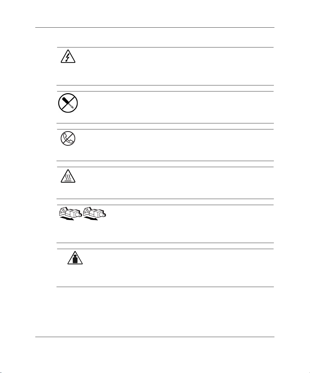
This symbol indicates the presence of hazardous energy circuits or electric
shock hazards. Refer all servicing to qualified personnel.
WARNING: To reduce the risk of injury from electric shock hazards, do not
open this enclosure. Refer all maintenance, upgrades, and servicing to
qualified personnel.
This symbol indicates the presence of electric shock hazards. The area
contains no user or field serviceable parts. Do not open for any reason.
WARNING: To reduce the risk of injury from electric shock hazards, do not
open this enclosure.
This symbol on an RJ-45 receptacle indicates a network interface connection.
WARNING: To reduce the risk of electric shock, fire, or damage to the
equipment, do not plug telephone or telecommunications connectors into this
receptacle.
This symbol indicates the presence of a hot surface or hot component. If this
surface is contacted, the potential for injury exists.
WARNING: To reduce the risk of injury from a hot component, allow the
surface to cool before touching.
These symbols, on power supplies or systems, indicate that the
equipment is supplied by multiple sources of power.
WARNING: To reduce the risk of injury from electric shock,
remove all power cords to completely disconnect power from the
system.
This symbol indicates that the component exceeds the recommended
weight for one individual to handle safely.
WARNING: To reduce the risk of personal injury or damage to the
equipment, observe local occupational health and safety requirements
and guidelines for manual material handling.
viii HP StorageWorks Modular Smart Array 500 System User Guide
Page 9
Rack Stability
WARNING: To reduce the risk of personal injury or damage to the equipment,
be sure that:
• The leveling jacks are extended to the floor.
• The full weight of the rack rests on the leveling jacks.
• The stabilizing feet are attached to the rack if it is a single-rack installation.
• The racks are coupled together in multiple-rack installations.
• Only one component is extended at a time. A rack may become unstable if
more than one component is extended for any reason.
Symbols in Text
These symbols may be found in the text of this guide. They have the following
meanings.
WARNING: Text set off in this manner indicates that failure to follow directions
in the warning could result in bodily harm or loss of life.
About This Guide
CAUTION: Text set off in this manner indicates that failure to follow directions could
result in damage to equipment or loss of information.
IMPORTANT: Text set off in this manner presents essential information to explain a concept
or complete a task.
NOTE: Text set off in this manner presents additional information to emphasize or supplement
important points of the main text.
HP StorageWorks Modular Smart Array 500 System User Guide ix
Page 10

About This Guide
Related Documents
For additional information on the topics covered in this guide, refer to the following
documentation:
• HP StorageWorks Modular Smart Array 500 System Hardware Configuration
and Installation Poster
• HP StorageWorks Modular Smart Array 500 Controller Installation Instructions
• HP DC Power Supply Option Installation Instructions
• HP 4-Port Shared Storage Module Option Installation Instructions
• HP M-Series Rack Rail Option Installation Instructions
• HP Smart Array Multipath Software User Guide
• HP StorageWorks Modular Smart Array 500 System Maintenance and Service
Guide
• Documentation CD
Getting Help
If you have a problem and have exhausted the information in this guide, you can get
further information and other help in the following locations.
Technical Support
In North America, call the HP Technical Support Phone Center at 1-800-652-6672.
This service is available 24 hours a day, 7 days a week. For continuous quality
improvement, calls may be recorded or monitored. Outside North America, call the
nearest HP Technical Support Phone Center. Telephone numbers for worldwide
Technical Support Centers are listed on the HP website,
Be sure to have the following information available before you call HP:
• Technical support registration number (if applicable)
• Product serial number
x HP StorageWorks Modular Smart Array 500 System User Guide
www.hp.com.
Page 11

• Product model name and number
• Applicable error messages
• Add-on boards or hardware
• Third-party hardware or software
• Operating system type and revision level
HP Website
The HP website has information on this product as well as the latest drivers and flash
ROM images. You can access the HP website at
Authorized Reseller
For the name of the nearest authorized reseller:
• In the United States, call 1-800-345-1518.
• In Canada, call 1-800-263-5868.
About This Guide
www.hp.com.
• Elsewhere, see the HP website for locations and telephone numbers.
Reader’s Comments
HP welcomes your comments on this guide. Please send your comments and
suggestions by e-mail to
HP StorageWorks Modular Smart Array 500 System User Guide xi
ServerDocumentation@hp.com.
Page 12

1
Component Identification
The HP StorageWorks Modular Smart Array 500 system is a rack-mountable 4U
SCSI storage system with redundant HP StorageWorks MSA500 controllers and
power supply/blower assemblies. Fault-tolerance support includes RAID 0, 1, 1+0, 5,
and Advanced Data Guarding (ADG), all with battery-backed cache. The Ultra3
SCSI hard drive interface supports Universal Hot-Plug tape drives with AIT and
DDS-4 technology and supports up to 14 (1-inch) universal hot-plug SCSI hard
drives.
HP StorageWorks Modular Smart Array 500 System User Guide 1-1
Page 13
Component Identification
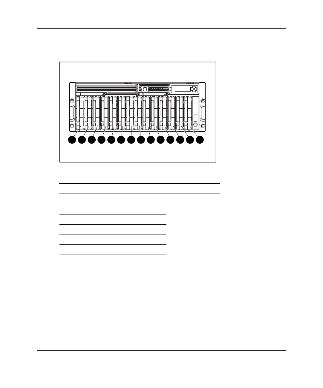
Front Panel Components
1
2
3
4
7
6
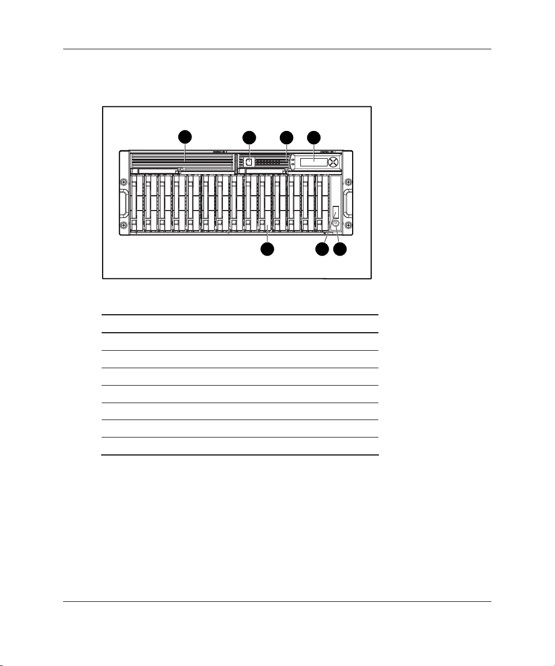
Table 1-1: Front Panel Components
Item Description
1 Bezel blank (bay for optional redundant controller)
2 Service port (for HP service technicians only)
3 Hot-plug MSA500 controller
4 Controller display
5 Power On/Standby button
6 Enclosure LEDs (Refer to Table 1-2)
7 Hot-plug SCSI hard drive bays with blanks
5
1-2 HP StorageWorks Modular Smart Array 500 System User Guide
Page 14
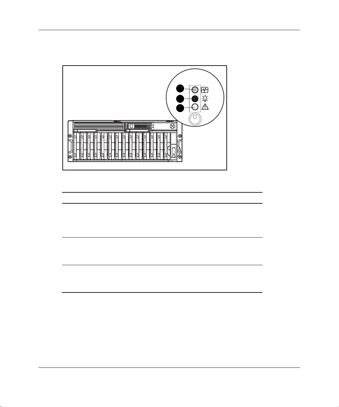
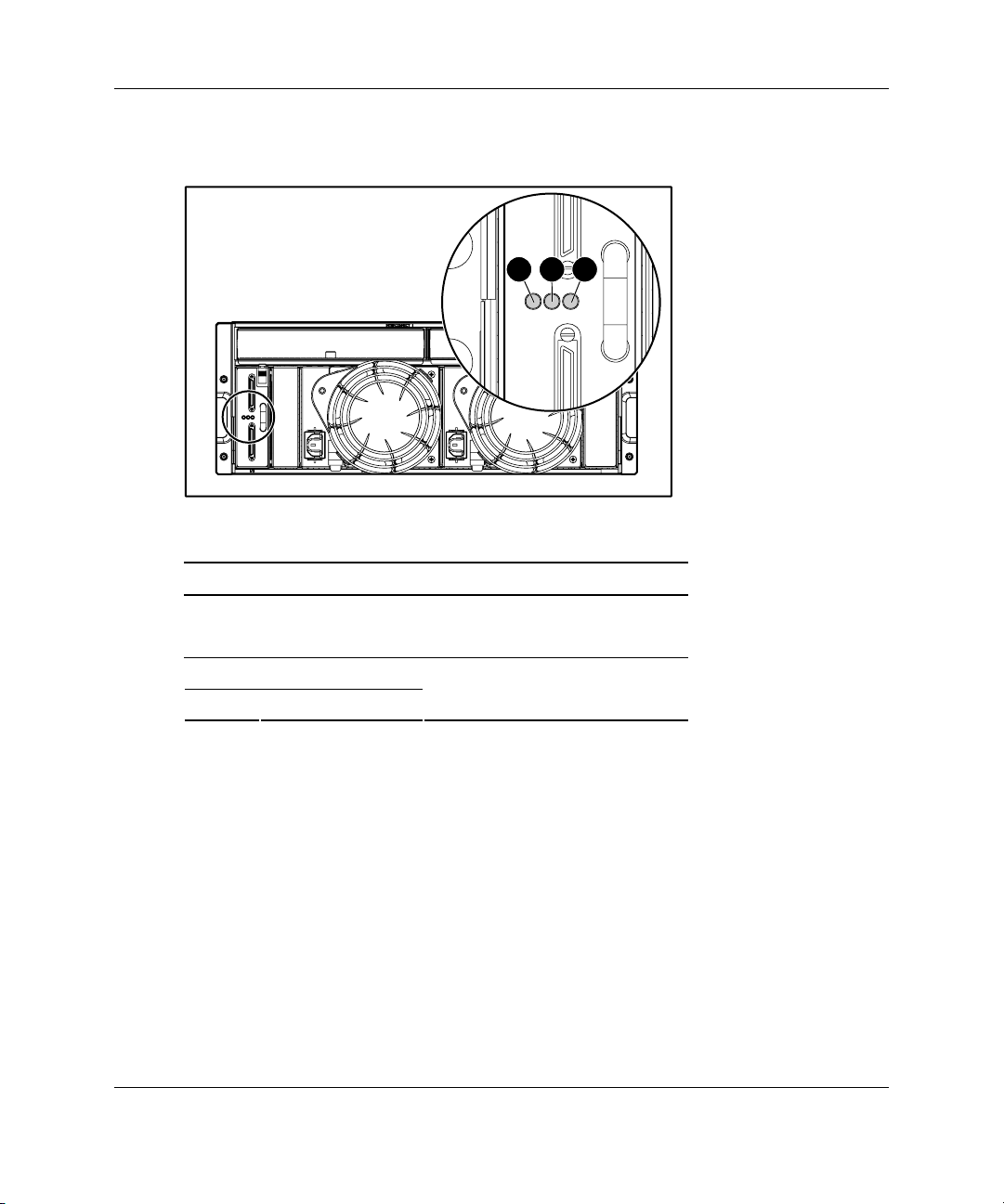
Enclosure LEDs
Component Identification
1
2
3
Table 1-2: Enclosure LEDs
Item LED Description Status
1 Environmental
Monitoring Unit
(EMU) heartbeat
2 System power Green = System power is On.
3 Fault Amber = Fault is detected in a
Green flashing = Shared storage module
is operating normally.
Green/Off = Shared storage module is
not operating normally.
Off = System is in standby mode or
power is removed from the system.
subsystem.
Off = No faults are detected.
IMPORTANT: The Power On/Standby button does not remove all power from the system. The
Standby mode removes power from most of the electronics and the drives, but portions of the
power supply and some internal circuitry remain active. To remove power completely,
disconnect all power cords from the equipment.
HP StorageWorks Modular Smart Array 500 System User Guide 1-3
Page 15
Component Identification
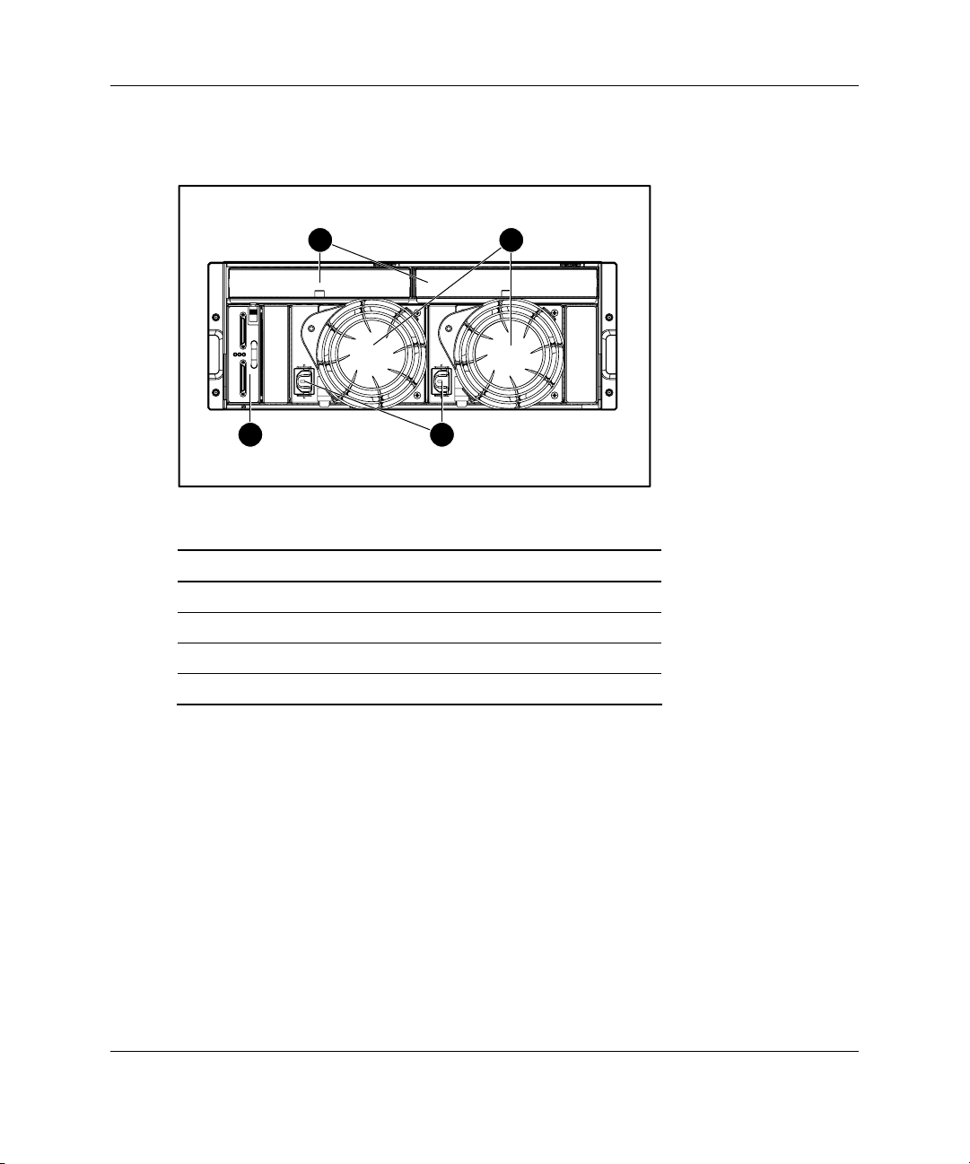
Rear Panel Components
1 2
4 3
Table 1-3: Rear Panel Components
Item Description
1 Interconnect blanks (required for proper airflow)
2 Power supply/blower assemblies
3 AC power connectors
4 2-Port Shared Storage Module
1-4 HP StorageWorks Modular Smart Array 500 System User Guide
Page 16
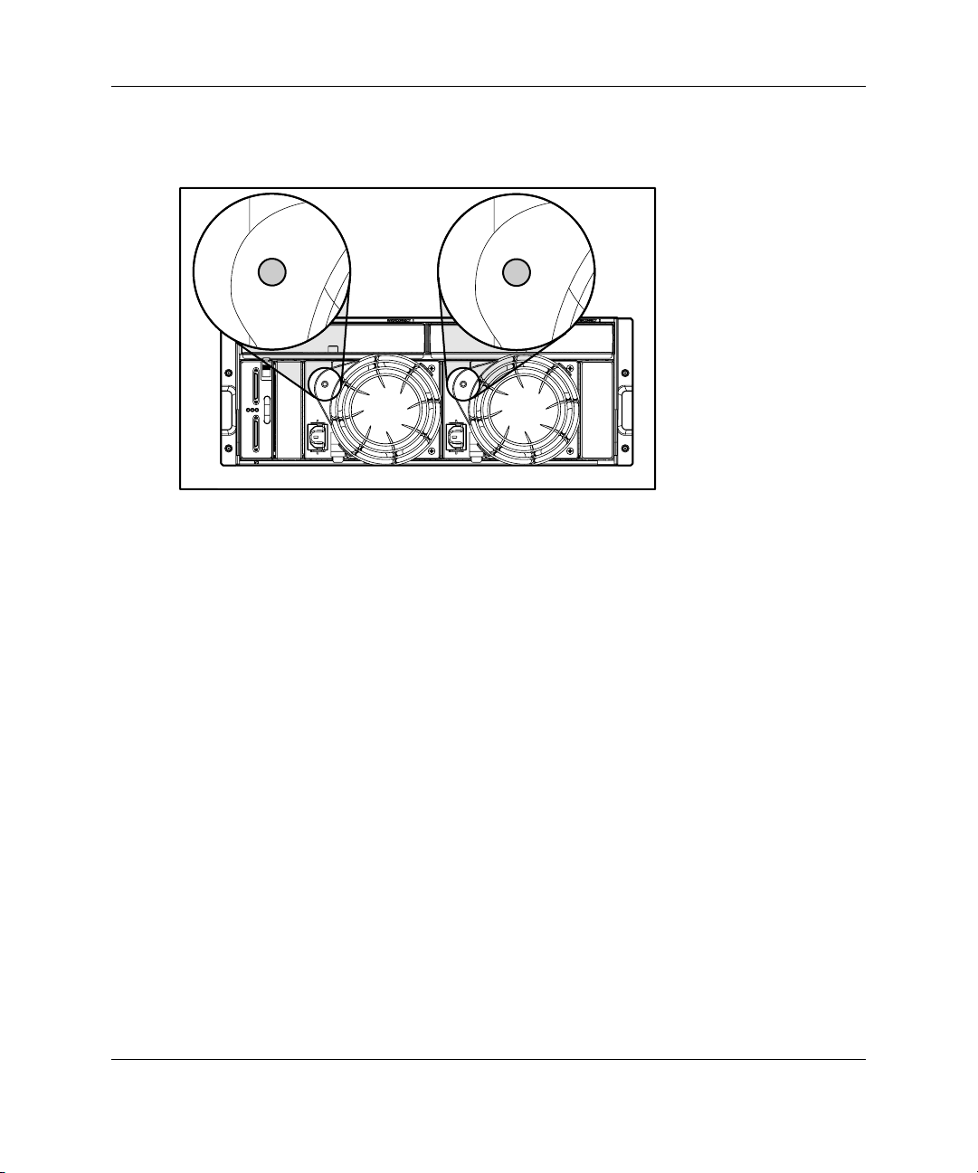
Power Supply/Blower Assembly LEDs
The power supply/blower assembly LEDs have the following functions:
• Green—The power supply is receiving power, and the blower is operating
normally.
Component Identification
• Off—No power is present; the power supply or the blower has failed.
HP StorageWorks Modular Smart Array 500 System User Guide 1-5
Page 17

Component Identification
Shared Storage Module with Integrated Environmental Monitoring Unit
The MSA500 system supports two-node clustering and up to four-node direct
attached storage (DAS) with Ultra3 SCSI I/O hardware. The system ships standard
with the 2-Port Shared Storage Module. A 4-Port Shared Storage Module is available
as an option.
Shared Storage Module Overview
Shared Storage Module functions include:
• Provides the interconnect function to server nodes
• Monitors the enclosure operation for:
— Temperature
— Power supplies
— Blowers
— Drive presence
• Detects and reports component changes in the enclosure (identifies hot-plug
addition and removal)
• Controls drive and enclosure LEDs
1-6 HP StorageWorks Modular Smart Array 500 System User Guide
Page 18
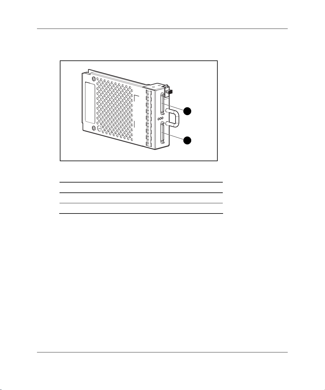
2-Port Shared Storage Module Components
1
2
Component Identification
Table 1-4: 2-Port Shared Storage Module Components
Item Description Bus
1 SCSI port connector A
2 SCSI port connector B
HP StorageWorks Modular Smart Array 500 System User Guide 1-7
Page 19
Component Identification
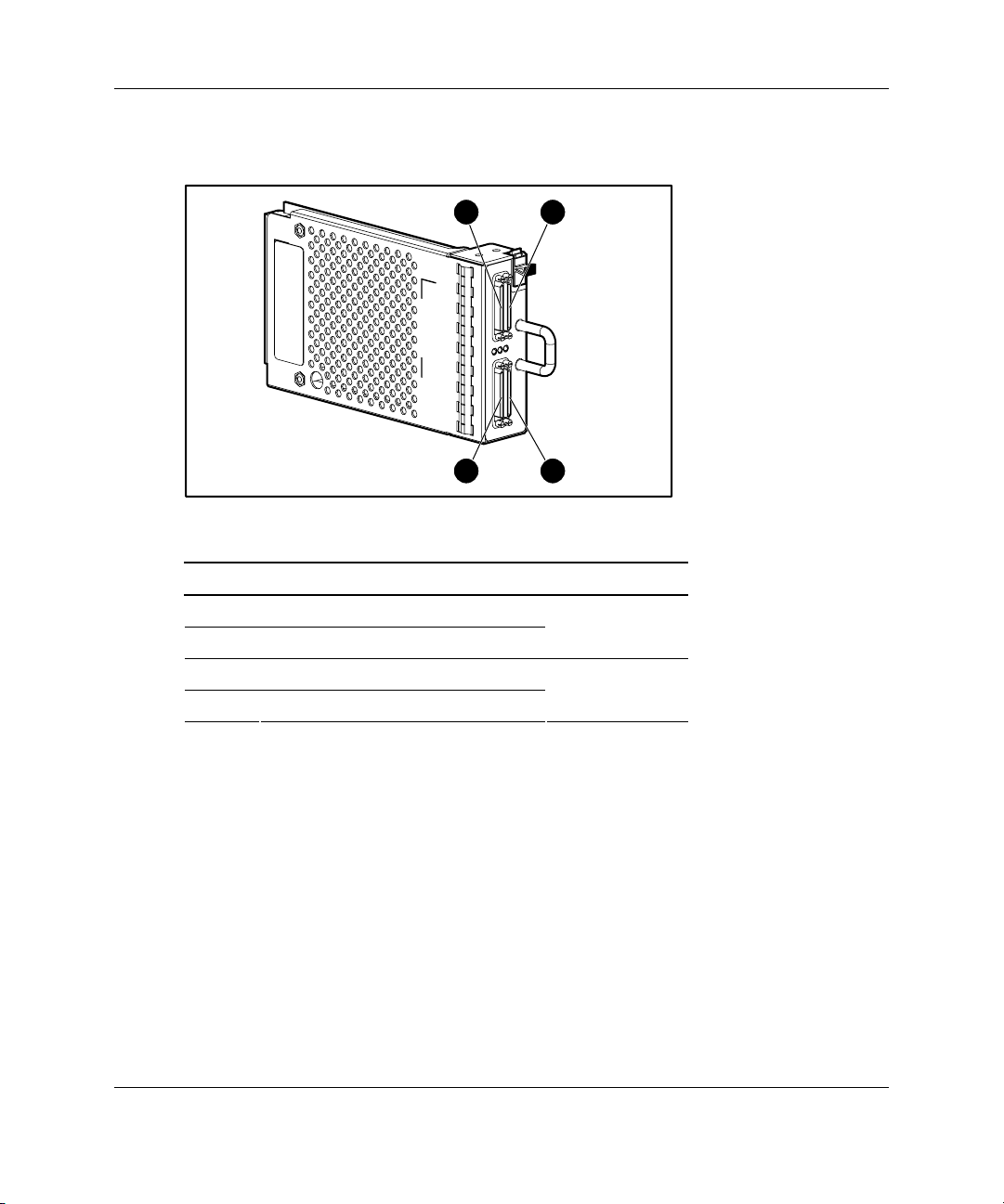
2-Port Shared Storage Module LEDs
1
2
3
Table 1-5: 2-Port Shared Storage Module LEDs
Item LED Description Status
1 Power Green = Power on
Off = Power off
2 SCSI host port A
3 SCSI host port B
Flashing green = On/Activity
Off = Off
1-8 HP StorageWorks Modular Smart Array 500 System User Guide
Page 20
4-Port Shared Storage Module Components
Component Identification
1
3
2
4
Table 1-6: 4-Port Shared Storage Module Components
Item Description Bus
1 SCSI port connector A1
2 SCSI port connector A2
3 SCSI port connector B1
4 SCSI port connector B2
A
B
HP StorageWorks Modular Smart Array 500 System User Guide 1-9
Page 21
Component Identification
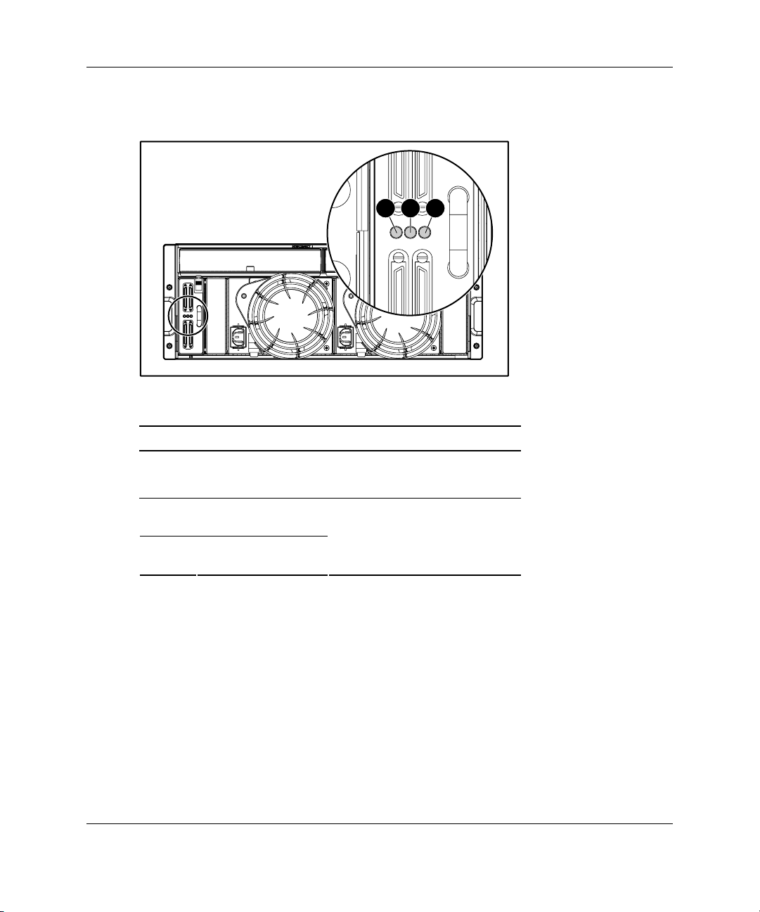
4-Port Shared Storage Module LEDs
1
2
3
Table 1-7: 4-Port Shared Storage Module LEDs
Item LED Description Status
1 Power Green = Power on
Off = Power off
2 SCSI host port A
connectors 1 and 2
3 SCSI host port B
connectors 1 and 2
Flashing green = On/Activity
Off = Off
1-10 HP StorageWorks Modular Smart Array 500 System User Guide
Page 22

Controller Components
Controller Display
Each MSA500 controller has an LCD display for informational and error messages.
Component Identification
1
Table 1-8: Controller Display
Item Description
1 Display
2 Left button
3 Up button
4 Right button
5 Down button
2
3
4
5
HP StorageWorks Modular Smart Array 500 System User Guide 1-11
Page 23
Component Identification
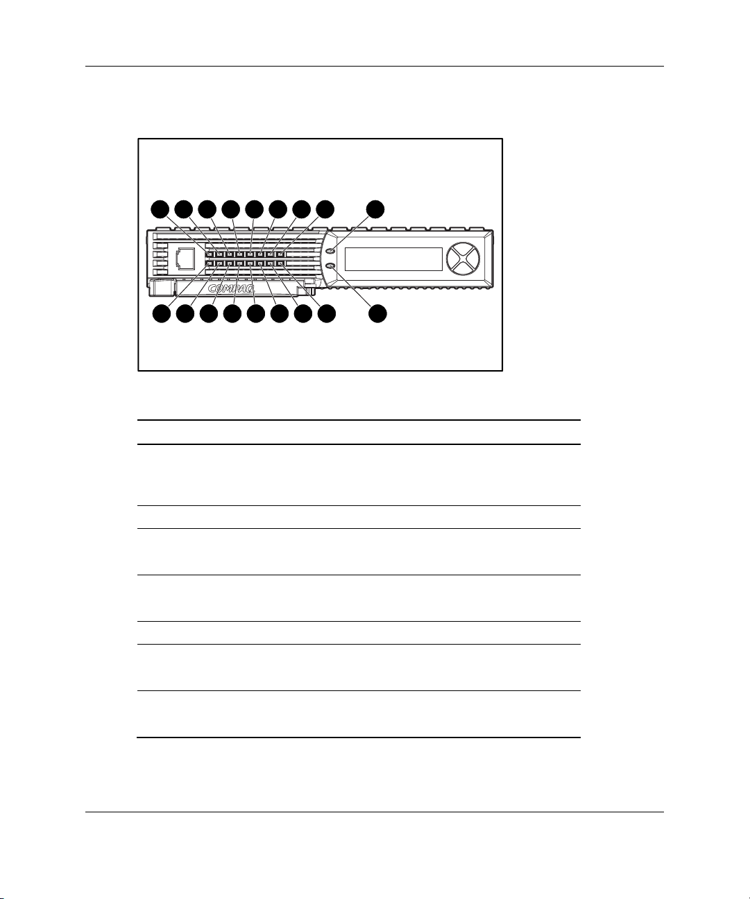
Controller LEDs
157146135124113102918 17
0 16
Table 1-9: Controller LEDs
Item LED Descriptions Status
0-2 Busy status Green = Controller is idle.
Off = Controller is operating at full
capacity.
3-5 No function —
6 Host port A
notification
7 Host port B
notification
8 Idle heartbeat Controller is idle and functioning.
9 Active/Standby Green = Controller is active.
10 DMA activity Green = DMA transfers are active.
Green = Notify On Event command active
Off = No Notify On Event command active
Green = Notify On Event command active
Off = No Notify On Event command active
Off = Controller is in standby.
Off = No DMA transfers.
continued
1-12 HP StorageWorks Modular Smart Array 500 System User Guide
Page 24

Table 1-9: Controller LEDs continued
Item LED Descriptions Status
11 Logical I/O activity Green = Currently processing logical
requests from the host adapter.
Off = No processing of logical requests
12 SCSI bus 0 activity
13 SCSI bus 1 activity
14 Cache activity Green = Cache activity
15 Drive failure Green = An array-configured drive has
16 Active redundancy Green = Controllers are operating with
17 Fault Amber = Error message received by
Green = Outstanding requests on the
SCSI bus
Off = No outstanding requests
Off = No cache activity
Flashing green = Cache transfer pending
failed.
Off = No drive failures
redundancy.
Off = No redundancy
controller display.
Off = No error message received or no
error message currently displayed.
Component Identification
HP StorageWorks Modular Smart Array 500 System User Guide 1-13
Page 25

Component Identification
Battery-Backed Cache Module Overview
The battery-backed cache module is a high-performance, 100-MHz SDRAM DIMM
read/write cache that increases performance in database and fault-tolerant
configurations.
Caching Functions
To enable faster data access from disk storage, the cache module performs two types
of caching:
• Posted-write caching—the controller writes user data in the cache memory on the
module rather than directly to the drives. Later, when the system is idle, the
controller writes the data to the drive array.
• Read-ahead caching—the controller detects sequential array access, reads ahead
into the next sequence of data, and stores the data in the read-ahead cache. Then,
if the next read access is for the cached data, the controller immediately loads the
data into system memory, avoiding the latency of a disk access.
Batteries
The cache module has two rechargeable and replaceable NiMH battery packs that
protect cached data during equipment failure or power outage:
• Up to 3 days protection for 256-MB cache DIMMs
• Up to for 4 days protection for 128-MB cache DIMMs
Under normal operating conditions, the battery packs should operate for 3 years
before replacement is necessary. The batteries recharge continuously when the
system is powered on.
NOTE: Temperature, age, and cache size may affect battery life.
The batteries also preserve data when you remove the cache module from the
controller. After you reinstall the cache module, and power is restored, the
initialization process writes the preserved data to the array. This feature is important
for data stored in the posted-write cache, but not yet written to an array.
1-14 HP StorageWorks Modular Smart Array 500 System User Guide
Page 26
SCSI IDs
Component Identification
1
8
9
10
11
12
7
6
5
4
3
2
Table 1-10: SCSI IDs
Bay SCSI ID Bus Port
1 0
2 1
3 2
4 3
5 4
6 5
7 8
0
13
14
continued
HP StorageWorks Modular Smart Array 500 System User Guide 1-15
Page 27

Component Identification
Table 1-10: SCSI IDs continued
Bay SCSI ID Bus Port
8 0
9 1
10 2
11 3
12 4
13 5
14 8
1
Hot-Plug SCSI Hard Drive LEDs
3
2
1
Table 1-11: Hot-Plug SCSI Hard Drive LEDs
Item LED Description
1 Activity
2 Online
3 Fault
1-16 HP StorageWorks Modular Smart Array 500 System User Guide
Page 28

Component Identification
Hot-Plug SCSI Hard Drive LED Combinations
Table 1-12: Hot-Plug SCSI Hard Drive LED Combinations
Activity
LED
On Flashing Off
Off Off On OK to replace the drive online.
Off, on, or
flashing
Off, on, or
flashing
Online
LED
On Off
On or Off Flashing A predictive failure alert has been received for this drive.
Fault
LED
Status
Do not remove the drive. Removing a drive during this
process can cause data loss in non-fault-tolerant
configurations.
• The drive is a replacement drive and is being rebuilt or
• If all online LEDs in a drive array are flashing, an
expansion is occurring.
The drive has failed and has been placed offline.
Do not remove the drive. Removing a drive during this
process can cause data loss in non-fault-tolerant
configurations.
The drive is online and configured as part of an array.
Replace the drive as soon as possible.
HP StorageWorks Modular Smart Array 500 System User Guide 1-17
Page 29

To install an MSA500 system:
1. Unpack the system. Refer to “Shipping Container Contents” in this chapter.
2. Install the system in a rack. Refer to “Installing the System into the Rack” in
this chapter.
3. Install hardware options, if applicable. Refer to procedures in Chapter 3,
“Hardware Options Installation.”
4. Connect SCSI cables and power cords. Refer to “System Cabling” in this chapter.
5. Power up the system. Refer to “System Power Up” in this chapter.
6. Configure arrays. Refer to Chapter 4, “Configuration and Utilities.”
Optimum Environment
2
Installation and Operation
When installing the MSA500 system in a rack, select a location that meets the
environmental standards described in Appendix E, “Specifications.”
For adequate airflow, use appropriate high-airflow inserts in rack cabinet doors and
observe industry standard practices for adequate spacing between racks or rows
of racks.
HP StorageWorks Modular Smart Array 500 System User Guide 2-1
Page 30

Installation and Operation
Warnings
WARNING: To reduce the risk of personal injury or damage to the equipment,
be sure that:
• The leveling jacks are extended to the floor.
• The full weight of the rack rests on the leveling jacks.
• The stabilizing feet are attached to the rack if it is a single-rack installation.
• The racks are coupled together in multiple-rack installations.
• Only one component is extended at a time. A rack may become unstable if
more than one component is extended for any reason.
WARNING: To reduce the risk of personal injury or equipment damage when
unloading a rack:
• At least two people are needed to safely unload the rack from the pallet. An
empty 42U rack can weigh as much as 115 kg (253 lb), can stand more than
2.1 m (7 ft) tall, and may become unstable when being moved on its casters.
• Never stand in front of the rack when it is rolling down the ramp from the
pallet. Always handle the rack from both sides.
Shipping Contents
Unpack the system shipping carton and locate the materials and documentation
necessary for installing the system. All the rack mounting hardware necessary for
installing the system into the rack is included with the rack or the system.
2-2 HP StorageWorks Modular Smart Array 500 System User Guide
Page 31

Shipping Container Contents
1
Installation and Operation
2
3
4
5
Table 2-1: Shipping Container Contents
Item Description Quantity
1 MSA500 system 1
2 Power cords 2
3 Ethernet crossover cable 1
4 SCSI VHDCI cables 2
5 4U rack template 1
6 Rack mounting hardware kit* 1
7 Documentation set* 1
*Not shown
In addition to these supplied items, you may need:
• Application software diskettes
• Options to be installed
HP StorageWorks Modular Smart Array 500 System User Guide 2-3
Page 32

Installation and Operation
Rack Mounting Hardware Kit Contents
The rack mounting hardware kit provides the required components for quick
deployment in Compaq branded, HP branded, and most square- and round-hole
third-party racks. The adjustable feature of the rack rails enables installation in racks
with depths of 69.90 to 73.81 cm (27.52 to 29.06 in).
If you are installing the MSA500 system in an M-Series rack, contact an authorized
reseller to obtain an M-Series Rack Rail option kit.
Table 2-2: Rack Mounting Hardware Kit Contents
Item Description Quantity
1 Rack rail (left) 1
2 Rack rail (right) 1
3 Pins for round-hole rack conversion 8
In addition to these supplied items, you may need a No. 2 Phillips screwdriver.
2-4 HP StorageWorks Modular Smart Array 500 System User Guide
Page 33

Installation and Operation
Converting the Rack Rails for Round-Hole Racks
The rack rails ship configured for square-hole racks. To convert the rack rails for use
in a round-hole rack:
1. Locate the bag of miscellaneous hardware that ships with the rack rails.
2. Locate the eight round-hole pins.
3. Use a No. 2 Phillips screwdriver to remove the standard pins from the front and
back ends of the rail.
HP StorageWorks Modular Smart Array 500 System User Guide 2-5
Page 34

Installation and Operation
4. Install four round-hole pins into the rail.
5. Repeat steps 3 and 4 for the second rail.
2-6 HP StorageWorks Modular Smart Array 500 System User Guide
Page 35

Installing the System into the Rack
To install the system in the rack:
1. Use the instructions provided on the rack template to mark the rack for rail
locations.
WARNING: The storage system weight, as assembled for shipping,
22.7 kg
50 lb
exceeds 22.7 kg (50 lb). Install the storage system in the lowest
available position in the rack.
Installation and Operation
HP StorageWorks Modular Smart Array 500 System User Guide 2-7
Page 36

Installation and Operation
IMPORTANT: Unless you are converting the rails for use in round-hole racks, do not
remove the pins from the ends of the rack rails. These load-bearing pins are designed to
fit through the holes without being removed.
NOTE: Identify the left (L) and right (R) rack rails by markings stamped into the sheet
metal.
2. Insert the front end of the left rack rail into the inside front of the rack. Be sure
that the pins extend through the holes marked during the rack template
procedure.
IMPORTANT: Be sure that the scissor-type locking latch engages when the end of the
rail seats into the rack uprights.
2-8 HP StorageWorks Modular Smart Array 500 System User Guide
Page 37

Installation and Operation
3. Slide the back end of the left rack rail into the inside rear of the rack. Be sure that
the pins extend through the holes marked during the rack template procedure.
IMPORTANT: Be sure that the scissor-type locking latch engages when the end of the
rail seats into the rack uprights.
4. Repeat steps 2 and 3 for the right rack rail.
HP StorageWorks Modular Smart Array 500 System User Guide 2-9
Page 38

Installation and Operation
5. Align the system with the rails and slide it into the rack.
22.7 kg
50 lb
WARNING: Always use at least two people to lift a storage system into the
rack. If the system is being loaded into the rack above chest level, a third
person MUST assist with aligning the system with the rails while the other
two people support the weight of the system.
CAUTION: To prevent storage system damage and ease insertion, support the
weight of the storage system and keep it level when sliding the storage system
into the rack.
WARNING: The storage system weight, as assembled for shipping,
exceeds 22.7 kg (50 lb). To reduce the risk of personal injury or
damage to the equipment, at least two people are required to lift the
storage system during removal or installation. Install the storage
system in the lowest available position in the rack.
2-10 HP StorageWorks Modular Smart Array 500 System User Guide
Page 39

6. Secure the system to the rack.
Installation and Operation
2
1
HP StorageWorks Modular Smart Array 500 System User Guide 2-11
Page 40

Installation and Operation
IMPORTANT: Use of the shipping bracket is required only when the rack is shipped with
the MSA500 system installed.
7. Use the shipping bracket to secure the system in the rack for shipping:
a. Loosen the thumbscrew on the shipping bracket.
b. Slide the shipping bracket forward until it engages the storage system
chassis.
1
2
c. Tighten the thumbscrew.
Installing Hardware Options
Install any hardware options before initializing the system. For options installation
information, refer to the option documentation or refer to Chapter 3, “Hardware
Options Installation.”
System Cabling
After installing the system in a rack, connect the SCSI cables and power cords to the
rear panel.
2-12 HP StorageWorks Modular Smart Array 500 System User Guide
Page 41

SCSI Cabling Guidelines
Always be sure that the servers attached to the storage system are powered down and
power cords are disconnected before connecting SCSI cables.
IMPORTANT: Before installing the Smart Array Multipath software on a server with a
Microsoft operating system, connect only one of the SCSI cables from each server to the
MSA500 system. Leave the second SCSI cable for the redundant path disconnected until
after the multipath software is installed.
For SSP cabling configurations, refer to “Selective Storage Presentation” in
Chapter 4.
Power Cords
The power cords should be approved for use in your country. The power cord must
be rated for the product and for the voltage and current marked on the electrical
ratings label for the product. The voltage and current rating of the cord should be
greater than the voltage and current rating marked on the product. In addition, the
diameter of the wire must be a minimum of 1.00 mm² or 18 AWG. If you are using
18 AWG, your maximum length may be up to 12 ft.
WARNING: To reduce the risk of electric shock or damage to the equipment:
• Do not disable the power cord grounding plug. The grounding plug is an
important safety feature.
• Plug the power cord into a grounded (earthed) electrical outlet that is easily
accessible at all times.
Installation and Operation
• Unplug the power cord from the power supply to disconnect power to the
equipment.
• Do not route the power cord where it can be walked on or pinched by items
placed against it. Pay particular attention to the plug, electrical outlet, and
the point where the cord extends from the system.
To connect AC power cords:
1. Connect the power cords to the power supplies.
2. Connect the power cords to the AC outlet.
HP StorageWorks Modular Smart Array 500 System User Guide 2-13
Page 42

Installation and Operation
For information about connecting DC power cords, refer to “DC Power Supply
Option” in Chapter 3.
System Power Up
Observe the following guidelines before powering up the system:
• Be sure that all components are powered down.
• Always install all components of the storage system and connect components to
the supported interconnect options.
• Install hard drives in the MSA500 system so the controller can identify and
configure them at power up.
CAUTION: You must power up the MSA500 system before powering up the servers.
It may take up to 2 minutes for the system to completely power up. Wait until the
display provides the “Startup Complete” message.
To power up the system:
1. Complete server hardware installation and cabling. Refer to the server
documentation.
2. Connect the SCSI cables and power cords to the MSA500 system. Refer to
“System Cabling” in this chapter.
IMPORTANT: When the power cord is connected to the AC or DC source, the system
automatically enters standby mode and provides power to certain system components.
3. Press the Power On/Standby button on the MSA500 system and observe the
system power LED and controller display. When the system goes from standby
to full power, the system power LED illuminates solid green, and the display
provides a “Startup Complete” message.
4. Power up the servers. Refer to the server documentation.
2-14 HP StorageWorks Modular Smart Array 500 System User Guide
Page 43

Controller Display
Each MSA500 array controller in the MSA500 system contains an integrated LCD
display. This module displays informational and error messages, shows the current
status of the module, and provides an interface for user input. The system combines
traditional POST messages issued by PCI-based array controllers with runtime event
notification messages for this new set of controller display messages. The display
module consists of the following components:
• A two-line, 20-column display text window
• Four buttons
• Two LEDs
Types of Messages
The display module is capable of storing up to 100 messages. When the message log
is full, the system deletes the oldest message to make room for the most recent one.
The types of messages include:
Installation and Operation
• Error Messages—Error messages indicate a problem that may require user
action.
The Fault LED illuminates when you view an error message. It also illuminates
to indicate that an unviewed error message is in the queue and was followed by
other types of messages. When scrolling backwards to view all error messages,
the LED illuminates only when an error message is in the text display window.
• Informational Messages—Informational messages provide feedback on
non-critical changes.
• User Input Messages—User input messages indicate an issue that requires a
choice. The user can choose a selection before the end of a time-out period or
allow the controller to default to a standard choice. User input messages only
occur during system power up.
The Fault LED flashes when a user input message is in the text display window
and requires input. If the user does not provide input within the time-out period,
the message remains, but the LED stops flashing.
HP StorageWorks Modular Smart Array 500 System User Guide 2-15
Page 44

Installation and Operation
For a complete list of messages and their meanings, refer to Appendix C, “Display
Messages.”
Using the Interface
• Scrolling—To view older messages, scroll backwards with the Up button
(indicated by the up arrow). To view newer messages, scroll forwards with the
Down button (indicated by the down arrow).
The arrival of new messages supersedes the display of any previous messages.
When a new message arrives, the display ignores its previous scrolling position
and presents the new message.
• Selecting User Input Options—User input messages present the user with a
choice and define the options in the text display window. Select one of the
options by pushing the left button (indicated by the left arrow) or the right button
(indicated by the right arrow).
• Deleting Messages—To delete a message, scroll to the message, then press the
left and right buttons simultaneously.
For information about controller LEDs, refer to Chapter 1, “Component
Identification.”
2-16 HP StorageWorks Modular Smart Array 500 System User Guide
Page 45

Before installing hardware options, be sure to update the system with the latest
firmware, as needed. For ROM flash software, refer to Chapter 4, “Configuration and
Utilities.” For firmware and software updates, refer to the HP website
www.hp.com/products/serverstorage
System Power Down
For some option installation procedures, you must power down the system.
To power down the system:
1. Power down any attached servers. Refer to the server documentation.
2. Press the Power On/Standby button on the storage system. Wait for the system
power LED to go from green to off.
3
Hardware Options Installation
3. Disconnect the power cords.
HP StorageWorks Modular Smart Array 500 System User Guide 3-1
Page 46

Hardware Options Installation
Hot-Plug SCSI Hard Drive Options
Observe the following guidelines when adding SCSI hard drives:
• If only one SCSI hard drive is used, install it in the bay with the lowest number.
• Hot-plug hard drives must be 1-inch universal SCSI types.
• Drives must be the same capacity to provide the greatest storage space efficiency
when drives are grouped together into the same drive array.
Removing Hard Drive Blanks
CAUTION: Always populate bays with either a component or blank. Proper airflow
can be maintained only when the bays are populated. Operating the system with
unpopulated bays can lead to improper cooling and thermal damage.
To remove a hard drive blank:
1
2
To install a blank, align the blank with the empty bay and push the blank inward until
it locks into place.
3-2 HP StorageWorks Modular Smart Array 500 System User Guide
Page 47

Replacing Hot-Plug SCSI Hard Drives
CAUTION: If you must replace a hot-plug drive, follow the guidelines in this section.
Failure to do so can result in data loss and can void the warranty.
RAID 0 is not a fault-tolerant configuration. Never remove a drive from a RAID 0
array unless it has failed. Drive failure is indicated by an amber drive failure LED. In
a RAID 0 configuration, removal of an operating drive results in data loss. To
remove a drive without losing data, always back up the entire array, replace the drive,
and restore the entire array. Backing up a single drive and replacing it does not
restore the array.
Some instances exist in which you may replace a drive in RAID 1, 5, and ADG
configurations. To determine when drive replacement is possible without data loss,
use the hot-plug SCSI hard drive LEDs combination table in Chapter 1, “Component
Identification.”
Follow these additional guidelines when replacing drives:
• Never remove more than one drive at a time (or two drives if you are using
ADG). When you replace a drive, the controller uses data from the other drives
in the array to reconstruct data on the replacement drive. If you remove more
than one drive, a complete data set is not available to reconstruct data on the
replacement drive(s) and permanent data loss could occur.
Hardware Options Installation
• Never remove a drive while the controller is rebuilding another drive. Each
drive has an online LED that flashes green while the drive is being rebuilt. The
controller requires the data from all other drives to rebuild the replacement drive.
• If the system has an online spare drive, wait for it to complete rebuilding
before replacing the failed drive. When a drive fails, the online spare becomes
active and begins rebuilding as a replacement drive. After the online spare has
completed Automatic Data Recovery (the online LED is continuously lit),
replace the failed drive with a new replacement drive. Do not replace the failed
drive with the online spare. The system automatically rebuilds the replacement
drive and resets the spare drive to an available state.
• If you replace a drive while the system is off, it may be necessary to rebuild
the replaced drive.
HP StorageWorks Modular Smart Array 500 System User Guide 3-3
Page 48

Hardware Options Installation
To replace a drive:
1. Be sure that the online and activity LEDs on the failed drive are both off.
2. Remove the failed drive.
2
1
3. Install the new replacement drive.
3
1
2
CAUTION: Data loss can occur if the drive is not firmly seated.
3-4 HP StorageWorks Modular Smart Array 500 System User Guide
Page 49

4. Be sure that the drive LEDs illuminate one at a time and then turn off together to
indicate that the system has recognized the new drive.
In fault-tolerant configurations, allow the replacement drive to be reconstructed
automatically with data from the other drives. While reconstruction is in
progress, the online LED flashes.
Universal Hot-Plug Tape Drive Option
The MSA500 system supports the Universal Hot-Plug Tape drive (AIT and DDS-4
types) for data storage and backup. The option supports Microsoft and Novell
operating systems in various configurations.
For specific Universal Hot-Plug Tape drive configurations, refer to the HP website
www.hp.com/products/sharedstorage
When installed, the hot-plug tape drive fills two storage system hard drive bays. For
complete information, refer to the documentation that ships with the Universal
Hot-Plug Tape drive.
Hardware Options Installation
To install a tape drive:
1. Remove two adjacent hard drive blanks. Refer to “Removing Hard Drive Blanks”
in this chapter.
CAUTION: Installation of the tape drive height converter is permanent.
Attempting to remove the converter after installation voids the tape drive
warranty.
HP StorageWorks Modular Smart Array 500 System User Guide 3-5
Page 50

Hardware Options Installation
2. Install the tape drive height converter on the tape drive.
NOTE: Hot-plug tape drives have a 1.6-inch form factor. Most hot-plug drive cages have
a 1-inch spacing between drive slots. When placing a 1.6-inch tape drive into a cage that
has 1-inch spacing, you must completely fill two slots in the drive cage to maintain proper
airflow. The drive height converter fills the remaining 0.4-inch.
3-6 HP StorageWorks Modular Smart Array 500 System User Guide
Page 51

3. Install the tape drive.
Hardware Options Installation
CAUTION: Data loss can occur if the drive is not firmly seated.
4-Port Shared Storage Module Option
The MSA500 system ships standard with a 2-Port Shared Storage Module. To
upgrade the unit and enable data transfer through four SCSI ports, install the optional
4-Port Shared Storage Module.
IMPORTANT: Before installing the 4-Port Shared Storage Module option, always upgrade to
the most recent firmware for the server host bus adapters (HBAs) and the MSA500
Controllers. The firmware upgrades ensure that HBAs can negotiate I/O paths with the storage
system controllers. For the most recent firmware, refer to the software CD that ships with the
Smart Array Multipath Software CD or refer to www.hp.com.
To install the module:
1. Power down the system. Refer to “System Power Down” in this chapter.
2. Disconnect the SCSI cabling connected to the 2-Port Shared Storage Module.
HP StorageWorks Modular Smart Array 500 System User Guide 3-7
Page 52

Hardware Options Installation
3. Remove the 2-Port Shared Storage Module.
4. Install the 4-Port Shared Storage Module.
1
2
3-8 HP StorageWorks Modular Smart Array 500 System User Guide
Page 53

Hardware Options Installation
HP StorageWorks Modular Smart Array 500 Controller Option
The system ships with one MSA500 controller. To provide redundancy and
maximize storage system uptime, install a second Smart Array controller.
Observe the following guidelines:
• If a controller has more than one cache DIMM, be sure that both DIMMs have
the same memory capacity.
• Always upgrade the cache in both controllers in a system with redundant
controllers.
• In a system with a redundant controller, be sure that both controllers have the
same number of DIMMs and that all DIMMs have the same memory capacity.
• To configure a MSA500 system for controller redundancy, both controllers must
execute the same version of firmware. If the controllers have different firmware
versions, the system responds as follows:
— In a hot-plug addition of the second controller, the system clones the
firmware version of the active controller onto the second controller. After the
second controller is reset, the controllers become redundant.
— In a non-hot-plug addition of the second controller, the system examines the
firmware versions of both controllers at power up and clones the most recent
version from one controller to the other controller.
For more information about upgrading firmware, refer to Chapter 4, “Configuration
and Utilities.”
HP StorageWorks Modular Smart Array 500 System User Guide 3-9
Page 54

Hardware Options Installation
To install an array controller:
1. Remove the bezel blank.
1
2
2. Open the locking latch on the redundant controller.
3. Install the controller.
3
2
1
4. Verify that the controller is seated properly by observing the controller LEDs.
When seated properly, the LEDs illuminate when the system is powered.
3-10 HP StorageWorks Modular Smart Array 500 System User Guide
Page 55

Cache Upgrade Option
The controller ships with a 128-MB battery-backed cache module. A 256-MB
battery-backed cache module is available as an option. Before installing a cache
upgrade, observe the following guidelines:
• Always power down the system before performing a cache upgrade.
• If a controller has more than one cache DIMM, be sure that both DIMMs have
the same memory capacity.
• Always upgrade the cache in both controllers in a system with redundant
controllers.
• In a system with a redundant controller, be sure that both controllers have the
same number of DIMMs and that all DIMMs have the same memory capacity.
To upgrade the cache:
1. Power down the system. Refer to “System Power Down” in this chapter.
2. Remove the controller.
Hardware Options Installation
3
1
2
HP StorageWorks Modular Smart Array 500 System User Guide 3-11
Page 56

Hardware Options Installation
3. Remove the existing cache module.
2
1
4. Install the new cache module.
3
4
3
2
1
3-12 HP StorageWorks Modular Smart Array 500 System User Guide
Page 57

Hardware Options Installation
5. Install the controller.
1
2
6. Power up the system. Refer to “System Power Up” in Chapter 2, “Installation
and Operation”.
7. Verify that the controller is seated properly by observing the controller LEDs.
When seated properly, the LEDs illuminate when the system is powered.
DC Power Supply Option
The DC power supply procedure provides instructions for converting an existing AC
power supply configuration to a DC power supply configuration.
Observe the required safety guidelines for DC power supply installation.
WARNING: A risk of personal injury from electric shock and hazardous energy
levels exists. The installation of options and routine maintenance and service
of this product must be performed by individuals who are knowledgeable
about the procedures, precautions, and hazards associated with DC
power products.
HP StorageWorks Modular Smart Array 500 System User Guide 3-13
Page 58

Hardware Options Installation
WARNING: To reduce the risk of electric shock, fire, and damage to the
equipment, this product must be installed in accordance with the following
guidelines:
• This power supply is intended only for installation in HP equipment located
in a restricted access location.
• This power supply is not intended for direct connection to the DC supply
branch circuit. It should be connected to a power distribution unit (PDU)
that provides an independent overcurrent-protected output for each DC
power supply. Each output overcurrent-protected device in the PDU must
be suitable for interrupting fault current available from the DC power source
and must be rated no more than 20A.
• This power supply is designed to be connected only to a DC power source
that can be classified as SELV or TNV, in accordance with applicable
national requirements for Information Technology Equipment and
Telecommunications Equipment. Generally, these requirements are based
on the International Standard for Information Technology Equipment, IEC
60950, and/or the European Telecommunication Standard ETC 300 132-2.
The DC source is to have one pole (Neutral/Return) reliably connected to
earth ground in accordance with local/regional electric codes and/or
regulations.
• The green/yellow lead of the power cord assembly must be connected to a
suitable ground/earth terminal located within the rack or cabinet. This
terminal must be connected to a suitable building ground/earth terminal in
accordance with local/regional electric codes/regulations. Do not rely on
the rack or cabinet chassis to provide adequate ground/earth continuity.
WARNING: The blower blades rotate at a high speed and do not stop
immediately when power is removed. Avoid touching the rotating blades when
removing the blower.
CAUTION: Do not operate the storage system with one AC power supply and one
DC power supply installed.
CAUTION: To prevent improper cooling and thermal damage, do not operate the
storage system unless both bays are populated with a power supply.
3-14 HP StorageWorks Modular Smart Array 500 System User Guide
Page 59

Hardware Options Installation
To install a DC power supply:
1. Power down the system. Refer to “System Power Down” in this chapter.
2. Determine the required length of the DC power cord:
WARNING: To reduce the risk of electric shock or damage to the
equipment, do not connect the power cord to the power supply until the
power supply is installed.
a. Place the power supply end of the DC power cord near the power supply bay.
Do not plug the DC power cord into a power supply.
b. Route the power cord to a PDU or other suitable DC power source. Do not
plug the DC power cord into the power source.
c. Trim the DC power cord as required.
3. Connect the free end of the DC power cord to the PDU or other suitable DC
power source.
4. Connect the free end of the green/yellow safety cable to a suitable earth ground.
IMPORTANT: If the power supply fails to operate, the red and black cables may be
connected incorrectly. When connected properly, the black cables should be at a higher
potential (more positive) relative to the red cable. The power supply features reverse
polarity protection so that no damage occurs if the power supply is connected incorrectly.
HP StorageWorks Modular Smart Array 500 System User Guide 3-15
Page 60
Hardware Options Installation
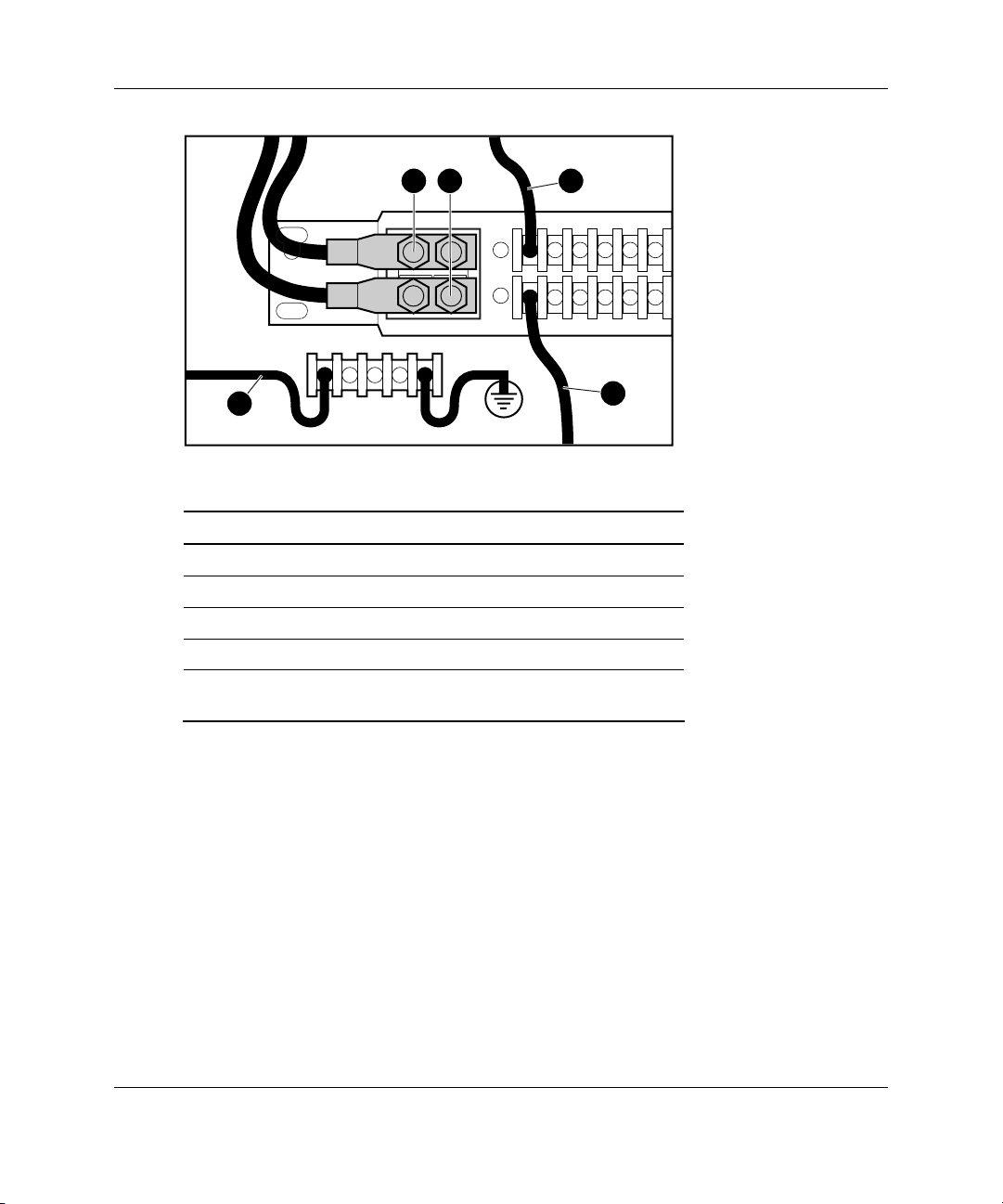
1 2 3
5
4
Table 3-1: DC Cabling Configuration
Item Description
1 -48 VDC cable from facility power source
2 -48 V return cable from facility power source
3 Red cable from power supply
4 Black cable from power supply
5 Green/yellow cable from power supply connecting to
rack chassis terminal block
3-16 HP StorageWorks Modular Smart Array 500 System User Guide
Page 61

5. Remove the existing AC power supply, if installed.
1
6. Remove the blower from the AC power supply.
Hardware Options Installation
2
1
2
1
HP StorageWorks Modular Smart Array 500 System User Guide 3-17
Page 62

Hardware Options Installation
CAUTION: Do not press on the center section of the blower because this action
can damage the blades. Press only on the outer edge of the blower.
7. Install the blower on the DC power supply.
8. Remove the protective cover from the connector pins on the DC power supply.
9. Slide the DC power supply into the bay.
1
2
3-18 HP StorageWorks Modular Smart Array 500 System User Guide
Page 63

Hardware Options Installation
10. Connect the DC power cord to the power supply.
2
1
11. Repeat steps 2 through 10 to install the second DC power supply.
12. Power up the system. Be sure that the power supply/blower assembly LED and
system power LED are green.
HP StorageWorks Modular Smart Array 500 System User Guide 3-19
Page 64

Server Utilities
HP utilities provide reporting functions that enable event-focused management and
diagnostics. To install and run these utilities, refer to the server documentation.
• Diagnostics Utility—This utility tests and verifies proper operation of the system
hardware. If problems are found, the utility isolates failure(s) down to the
replaceable part, whenever possible. When an operating system is installed with
SmartStart Version 5.30 or later, the Diagnostics and utilities are installed on a
partition of the hard drive that contains the operating system. (This hard drive
may or may not be located in the storage system.) Always access these utilities
when a system configuration error is detected during POST.
• INSPECT Utility—This utility provides a report detailing system information.
• Insight Manager 7—This Web-based application enables system administrators
to accomplish normal administrative tasks from any remote location, using a
Web browser. Insight Manager 7 provides device management capabilities that
consolidate and integrate management data from HP and third-party devices.
4
Configuration and Utilities
• Insight Management Agents—These agents enable easy manageability of the
server through Insight Manager 7 software and third-party SNMP management
platforms. Management agents monitor key subsystems that are instrumental in
making health, configuration, and performance data available to the agent
software. The agents act upon that data by initiating alarms in the event of faults.
The agents also provide updated management information, such as network
interface or subsystem performance statistics, to the management systems.
HP StorageWorks Modular Smart Array 500 System User Guide 4-1
Page 65

Configuration and Utilities
• Survey Utility—This utility gathers critical hardware and software information
on servers running Microsoft Windows and Novell NetWare operating systems.
If a significant change occurs between data-gathering intervals, the Survey
Utility marks the previous information and overwrites the Survey text files to
reflect the latest changes in the configuration.
Recovery Server Option
The HP ProLiant Essentials Recovery Server Option (RSO) software kit supports a
standby recovery server configuration. This configuration comprises two identical
(and identically configured) ProLiant servers connected to a common MSA500
system and a common network. One of the servers (the primary) supports network
clients by default. The other server remains in a preboot stage during normal use and
acts as a backup (recovery) server. All hard drive storage is located in the shared
storage system. The storage system also contains a single copy of the operating
system and all the applications, drivers, and data.
When a system fault occurs in either the server or operating system, RSO
automatically takes the primary server offline and initializes the recovery server to
take over operations. While the recovery server is supporting network clients, the
primary server can be repaired at leisure.
For more information about configuring RSO, refer to the HP ProLiant Essentials
Recovery Server Option User Guide that ships with the software.
For installation procedures, refer to the HP ProLiant Essentials Recovery Server
Option Pack Installation Instructions that ships with the software.
4-2 HP StorageWorks Modular Smart Array 500 System User Guide
Page 66

ROM Functions and Utilities
Each MSA500 controller has a ROM that contains the controller firmware.
Recovery ROM
The Recovery ROM feature stores two complete firmware images in the ROM: one
active image and one backup image. When the controller is powering up, it checks
both firmware images to be sure they are valid. If either image is invalid, the system
overwrites the invalid image with the valid image. This process, commonly called
auto-flashing, is performed automatically by the controller and does not require any
user intervention. The controller display provides messages for the status of this
process.
Firmware Upgrades
The ROM flash tool enables system administrators to efficiently upgrade array
controller ROM images. This tool has the following features:
• Supports Microsoft® Windows NT® 4.0, Windows® 2000, Novell NetWare
(offline only), and Linux operating systems
Configuration and Utilities
• Integrates with other software maintenance, deployment, and operating system
tools
• Automatically checks for hardware, firmware, and operating system
dependencies, and installs only the correct ROM upgrades required by each
target controller
For firmware procedures, refer to the SmartStart CD.
HP StorageWorks Modular Smart Array 500 System User Guide 4-3
Page 67

Configuration and Utilities
Controller Firmware Auto Cloning
In a redundant controller configuration, both controllers must execute the same
version of firmware. During power up (or when a redundant controller is installed as
a hot-plug procedure), the system compares the controller firmware versions. If the
versions differ, the controller displays a user input message seeking to initiate
Controller Firmware Auto Cloning. If 60 seconds elapse with no user input, cloning
begins automatically, and the system overwrites one firmware version with the other
version.
When the cloning is complete, the system resets the modified controller. After the
modified controller powers up, the controllers begin operating in redundant mode.
The system clones firmware based on the following criteria:
• Non-Hot-Plug Cloning—If the system powers up with both controllers installed,
the system clones the most recent firmware version from either controller.
• Hot-Plug Cloning—If the system is operating and an optional redundant
controller is installed, the system clones the firmware version from the primary
controller, regardless of which firmware version is more recent. This cloning
method ensures that all host-initiated I/O remains uninterrupted during system
operation.
• Incompatible Version Cloning—If a specific version of firmware is
incompatible with certain hardware revisions of a controller, the system displays
the user input message seeking to initiate Controller Firmware Auto Cloning and
clones the most recent firmware version that is compatible with both controllers.
IMPORTANT: During incompatible version cloning, the system does not reset the
updated controller if the controller is operating and processing I/O. In this case, the system
does not enter redundant mode and provides an informational message on the controller
display. To configure redundancy, cycle the system power. Refer to “System Power
Down” in Chapter 3.
4-4 HP StorageWorks Modular Smart Array 500 System User Guide
Page 68

Selective Storage Presentation
SSP is a controller firmware feature that enables the administrator to control access
from multiple hosts to logical drives on the MSA500 system. The administrator
selects which server host or hosts can access the stored data, restricting access as
needed to assure data integrity and security.
Each logical drive on the controller has an access control list that contains the IDs of
the server host adapters that have access to the drive. If a server attempts to send
commands to a logical drive without access authority, the controller rejects the
command.
The configuration utility maps the IDs of server host adapters to connection names
and sets up access control lists for logical drives based on the adapter IDs.
SSP Hardware Configurations
To configure the hardware for SSP, use SCSI cables to connect each server to the
2-Port or 4-Port Shared Storage Module installed in the storage system. Boot
volumes for individual servers can reside on server drives or storage system drives.
Configuration and Utilities
Firmware Requirements
For Selective Storage Presentation (SSP) support on the MSA500 system, be sure the
following firmware versions are present:
• MSA500 Controller firmware Version 1.66 or later
• Smart Array 532, 5i, or 5i+ Controller firmware Version 2.36 or later
For the most recent firmware, refer to the software CD that ships with the MSA500
system or refer to
www.hp.com
HP StorageWorks Modular Smart Array 500 System User Guide 4-5
Page 69

Configuration and Utilities
Enabling SSP
After choosing the configuration that best suits your needs, enable SSP with
ACU Version 6.0 or later. Locate ACU on the SmartStart CD. For instructions, refer
to the HP Array Configuration Utility User Guide on the Documentation CD.
Array Configuration Utility
ACU Version 6.0 (or later) is a browser-based utility with the following features:
• Supports online array capacity expansion, logical drive capacity extension,
assignment of online spares, and RAID or stripe size migration
• Suggests the optimum configuration for an unconfigured system
• Provides different operating modes, enabling faster configuration or greater
control over the configuration options
• Remains available any time that the server is on
• Displays on-screen tips for individual steps of a configuration procedure
The minimum display settings for optimum performance are 800 × 600 resolution
and 256 colors. The server must have Microsoft Internet Explorer 5.5 (with Service
Pack 1) installed and be running Microsoft Windows 2000, Windows NT 4.0, or
Linux. Refer to the README.TXT file for further information about browser and
Linux support.
For more information about ACU Version 6.0 (or later), refer to the HP Array
Configuration Utility User Guide on the Documentation CD.
Moving Array Controller Drives and Arrays
CAUTION: Back up all data before removing drives or changing configurations.
Failure to do so could result in permanent loss of data. Before moving drives and
arrays, run ACU.
4-6 HP StorageWorks Modular Smart Array 500 System User Guide
Page 70

Configuration and Utilities
Drives can be moved to other ID positions on the same array controller. You can also
move a complete array from one controller to another, even if the controllers are on
different servers or storage devices. Arrays on different controllers can also be moved
to another controller.
Before moving drives, observe the following requirements:
• No drives are failed, missing, or degraded.
• The move does not result in more than 14 physical drives.
• No more than 32 logical volumes are configured for a controller.
• The array must be in its original configuration with no active spare drives.
• Capacity expansion is not running.
• Controller firmware is the latest version (recommended).
• Controller is a Smart Array controller.
Before moving an array from one controller to another, observe these additional
requirements:
• All drives in the array must be moved at the same time.
• Drive positions of the destination controller must match original drive positions.
When all requirements are met:
1. Power down the system. Refer to “System Power Down” in Chapter 3.
2. Move the drives. Refer to “Hot-Plug SCSI Hard Drive Options” in Chapter 3.
3. Power up the system. Refer to “System Power Up” in this chapter.
A #86 controller display message should appear, indicating that drive positions
were changed and the configuration was updated. If a #121 controller display (no
volumes) message is displayed, power down the system immediately to avoid
data loss, and return the drives to their original locations.
For more information about display messages, refer to Appendix C, “Display
Messages.”
4. Check the new drive configuration by running ACU. Refer to the HP Array
Configuration Utility User Guide on the Documentation CD.
HP StorageWorks Modular Smart Array 500 System User Guide 4-7
Page 71

Configuration and Utilities
Expanding and Extending Capacity
CAUTION: Back up all data before removing drives or changing configurations.
Failure to do so could result in permanent loss of data. Before moving drives and
arrays, run ACU.
Array Capacity Expansion is the addition of physical drives to an array that has
already been configured. The capacity of these added physical drives may then
be added to an existing logical drive on the array (capacity extension; refer to the
next paragraph), or it may be configured into a new logical drive.
Logical Drive Capacity Extension is the enlargement of an existing logical
drive after the corresponding array has undergone capacity expansion.
Use ACU to perform capacity expansion and extension. A data backup and
restoration cycle is not required, even in non-fault-tolerant configurations.
With hot-plug drives, you can perform expansion online. Online extension is only
possible with operating system support.
IMPORTANT: When extending a logical drive under Microsoft Windows 2000, upgrade the
disk to DYNAMIC before creating a partition on that disk. If the disk already has a partition
when it is upgraded to DYNAMIC, Windows 2000 may not allow logical drive extension. Refer
to the Windows 2000 documentation for details about DYNAMIC and BASIC disks.
IMPORTANT: Microsoft Windows NT 4.0 only allows four partitions on each logical drive.
Additional drive space created may not be accessible if the four partitions per logical drive limit
are exceeded.
IMPORTANT: If you are running Microsoft Windows 2000 with Microsoft Cluster Services
(MSCS), logical drive extensions are not recommended. MSCS requires that disks be
configured as BASIC in logical disk manager. In order to take advantage of logical drive
extension, the drives would have to be configured as DYNAMIC when the volume is initially
created. Because of the differences in requirements for MSCS and the logical drive extension
feature, we recommend you do not perform a logical drive extension on a storage enclosure
that is part of a Microsoft Cluster.
4-8 HP StorageWorks Modular Smart Array 500 System User Guide
Page 72

Configuration and Utilities
Array Diagnostics Utility
ADU collects all possible information about the array controllers in the system and
generates a list of detected problems. You can save this data to a file for analysis. In
most cases, ADU provides sufficient information for troubleshooting procedures.
To obtain ADU, download the utility from the HP website
www.hp.com
NetWare Online Array Configuration Utility (CPQONLIN)
The NetWare Online Array Configuration Utility, also called CPQONLIN, is a
NetWare Loadable Module (NLM) for configuring drive arrays without shutting
down the server. CPQONLIN also provides information about the status of drives
attached to the MSA500 controller. It indicates drive failure, expansion, or waiting
for expansion or rebuild (queued). Before loading CPQONLIN.NLM, you must load
the appropriate device drivers⎯CPQFC.HAM and CPQSHD.CDM.
CPQONLIN.NLM is located in the ONLINE directory of Novell SSD Disk 4.
IMPORTANT: CPQONLIN does not support SSP configurations. Use ACU 6.0 offline to
enable SSP configurations in a NetWare environment.
HP StorageWorks Modular Smart Array 500 System User Guide 4-9
Page 73
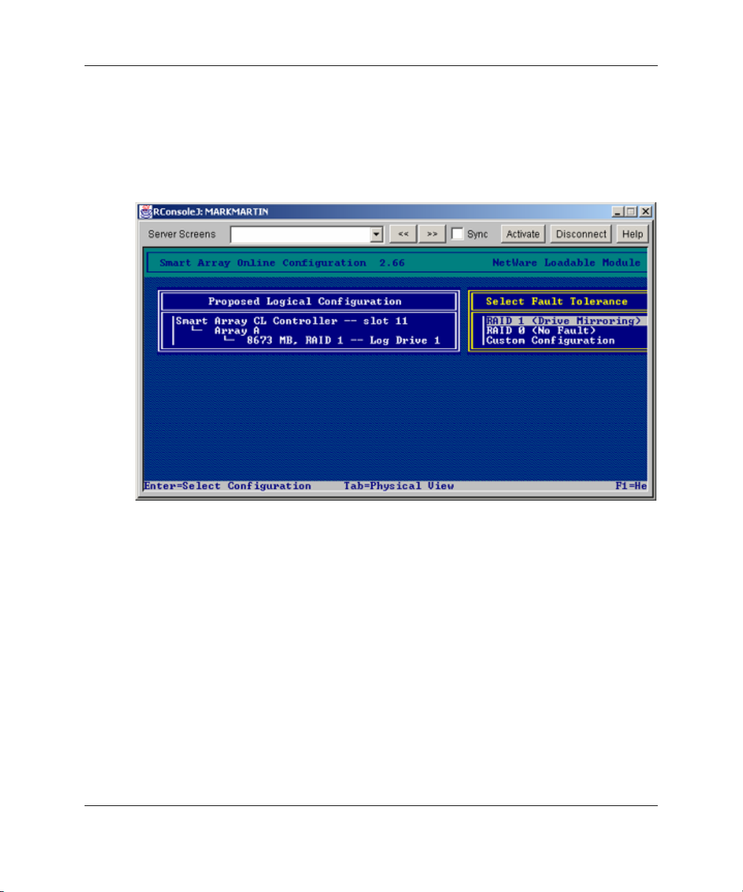
Configuration and Utilities
Auto-configuration
If no logical drives are configured, a CPQONLIN auto-configuration wizard appears
and prompts you to select fault-tolerance information. CPQONLIN then configures
arrays optimally for the selected fault tolerance.
4-10 HP StorageWorks Modular Smart Array 500 System User Guide
Page 74

Custom Configuration
Custom configuration allows you to create arrays and assign fault tolerance one array
at a time. To custom configure an array:
1. Go to the Main Configuration View screen.
2. Highlight the controller, array, or logical drive to be configured.
3. Make a selection from the Options menu located on the right side of the screen.
The following figure shows the controller highlighted on the left side of the
screen and Controller Options menu on the right side of the screen.
Configuration and Utilities
4. Use online help for on completing configurations. The following sections discuss
CPQONLIN functions.
HP StorageWorks Modular Smart Array 500 System User Guide 4-11
Page 75

Configuration and Utilities
Drive Rebuild, Expand Priority, and Accelerator Ratio
To set the drive rebuild priority, expand priority, or accelerator ratio for a controller:
1. Go to the Main Configuration View screen.
2. Highlight the controller.
3. Select the Controller Settings option listed below Controller Options. The
Controller Settings screen appears.
Drive Rebuild
Drive rebuild occurs after a physical drive fails and is replaced. Only logical drives
configured for fault tolerance (RAID 1, RAID 5, ADG) on the array with the failed
physical drive will rebuild.
4-12 HP StorageWorks Modular Smart Array 500 System User Guide
Page 76

Configuration and Utilities
Priority Settings
To set the drive rebuild priority:
1. Highlight the MSA500 controller.
2. Select the controller settings.
— If you choose low priority for drive rebuild, drive rebuilding takes place
when I/O to the drive is inactive.
— If you choose high priority, drive rebuilding occurs faster, at the expense of
normal I/O operations.
Accelerator Ratio
The MSA500 controller has an onboard cache called an Array Accelerator, which
performs both write-posting and read-ahead caching. The setting in CPQONLIN
determines the amount of memory allocated to the read and write caches. For
example, if the Accelerator Ratio is set to Read 75%:Write 25%, 75% of Array
Accelerator cache is dedicated to read-ahead cache and 25% is dedicated to the writeposting cache. This option can be modified from the controller Settings menu.
Expanding an Array
During an expand, performance may be slightly degraded. In most cases, however,
any potential degradation is offset by the addition of physical drives. Some tips for
expanding include:
• Perform the expand process during periods of low server use. If you must expand
during peak periods, ACU for NetWare enables you to set the priority of the
expand. Setting the priority to LOW affects performance the least, but it takes
longer for the new space to become available.
• When expanding, always add drives with a capacity equal to or greater than the
capacity of the smallest drive in the array. Adding larger drives wastes space
because only the space that is equal to the smallest drive size can be used.
HP StorageWorks Modular Smart Array 500 System User Guide 4-13
Page 77

Configuration and Utilities
Adding or Configuring Spare Drives
When adding a spare drive to an array, there must be an unassigned drive or a drive
already assigned as a spare on another array. You can assign a single spare to any
number of arrays or assign separate spares. When you select Assign Spare Drive,
only drives that qualify will appear (for example, only those spares that are large
enough will appear). If drives that you expect to see do not appear, switch to the
physical drive view (Tab key), and check the size of the drives. The capacity of the
spare must be equal to or greater than the capacity of the smallest drive in the array.
Online RAID and Stripe Migration
Using CPQONLIN, you can modify both the RAID level and stripe size of an
existing logical drive while online. To migrate a drive:
1. Select the drive setting option under the logical drive menu for the drive you
intend to modify.
2. Select the new RAID level and/or stripe size from the choices presented to you.
If the new settings are valid, the migration will begin when you save the changes.
Failed Drives or Interim Recovery Mode
If a drive fails and hardware fault tolerance is enabled, operation continues. Replace
the drive as soon as possible. Select a logical drive and press the F3 key to monitor
the status of drive recovery.
4-14 HP StorageWorks Modular Smart Array 500 System User Guide
Page 78

Configuration and Utilities
Drive status messages include:
• Interim Recovery: The logical drive is operating, but a failed drive has not been
replaced. Replace drive as soon as possible.
• Ready for Recovery: The logical drives are queued for recovery. This status is
displayed when another logical drive is already rebuilding or expanding.
• Rebuilding: The array is operating and rebuilding a replacement drive or an
online spare, if one was assigned.
• Logical Drive Failed: If you have one or more logical drives that are not
protected by fault tolerance in an array, the data on these logical drives will be
lost. ACU shows the logical drives as FAILED. After drive replacement, any
fault-tolerant logical drives rebuild. The logical drives that were not protected
(FAILED) become available for data (the devices are reactivated automatically).
If you have a backup of the data, restore the data now.
If you do not replace the failed drive, the only option using ACU is to delete
logical drives. Do not delete logical drives that contain valid data. Doing so
results in data loss.
HP StorageWorks Modular Smart Array 500 System User Guide 4-15
Page 79

Configuration and Utilities
NOTE: A failed status can occur on drives protected by fault tolerance if two or more
physical drives fail concurrently.
Some status messages are available without pressing the F3 key. For example, on the
Main menu, the FAILED status appears next to the logical drive that has failed.
EXPANDING and REBUILDING appear next to the array in which the activity is
occurring.
Handling Disk Drive Failures
If the MSA500 controller was configured with hardware fault tolerance, complete the
following steps after a disk drive failure.
1. Determine which physical drive failed. On hot-plug drives in a ProLiant server or
storage system, failure is indicated by an amber drive failure LED on each drive
tray.
2. If the unit containing the failed drive does not support hot-plug drives, perform a
normal system shutdown.
3. Remove the failed drive and replace it with a drive that is of the same capacity.
For hot-plug drives, after you secure the drive in the bay, the LEDs on the drive
each flash once in an alternating pattern to indicate that the connection was
successful. The online LED flashes, indicating that the controller recognized the
drive replacement and began the recovery process.
4. Power up the server, if applicable.
5. The MSA500 controller firmware reconstructs the information on the new drive,
based on information from the remaining physical drives in the logical drive.
While reconstructing the data on hot-plug drives, the online LED flashes. When
the drive rebuild is complete, the online LED is illuminated.
6. NetWare cannot detect a single physical drive failure when using hardware-based
fault tolerance; NetWare determines that the data is still valid and accessible
during the rebuilding process. However, the driver knows that a physical drive
has failed. A message is printed on the console notifying the user that a physical
drive is in a degraded state. CPQONLIN will also show the drive has failed.
4-16 HP StorageWorks Modular Smart Array 500 System User Guide
Page 80

Optimizing Array Controller Performance
To improve system performance, keep these tips in mind before creating NetWare
volumes or partitions:
• If you selected a fault-tolerance option, such as mirroring or distributed data
guarding, when using the System Configuration Utility, do not select mirroring
while using INSTALL.NLM. The fault-tolerance capabilities of the MSA500
controller provide performance improvements and automatic data recovery
features.
• Novell recommends creating volumes with a 64-KB block size and using the
Block Sub-Allocation feature of NetWare. Using a large block size decreases the
amount of RAM required to mount the volume, while Block Sub-Allocation
allows NetWare to allocate disk space more efficiently.
Configuration and Utilities
HP StorageWorks Modular Smart Array 500 System User Guide 4-17
Page 81

Cluster Installation and Configuration
Cluster Hardware Installation
To install the cluster:
1. Select an installation site that meets the optimum environment requirements.
Refer to the server documentation.
2. Install the storage system into the rack. Refer to Chapter 2, “Installation and
Operation.”
3. Install the servers into the rack, directly above the storage system. Refer to the
server documentation.
IMPORTANT: Do not power up the storage system or servers at this time.
4. Install options:
5
— To install storage system options, refer to Chapter 3, “Hardware Options
Installation.”
— To install server options, refer to the server documentation or the
documentation that ships with the option.
5. Cable the system:
a. Install the server cable management arms. Refer to the server documentation.
HP StorageWorks Modular Smart Array 500 System User Guide 5-1
Page 82

Cluster Installation and Configuration
b. Connect the VHDCI SCSI cables to the storage system and servers.
For Microsoft or Linux operating systems, connect the Ethernet crossover
cable between the servers. Use the RJ-45 connectors identified as NIC 1 on
each server.
c. Connect peripheral devices, such as a keyboard, mouse, or monitor.
IMPORTANT: HP recommends the use of a KVM switchbox. Refer to the documentation
that ships with the switchbox.
6. Connect the power cords.
IMPORTANT: HP recommends the use of an uninterruptible power supply (UPS).
Contact the nearest authorized reseller.
7. Depending on the operating system, use the appropriate installation instructions
provided on the HP website:
http://www.hp.com/servers/proliant/highavailability
5-2 HP StorageWorks Modular Smart Array 500 System User Guide
Page 83

Regulatory Compliance Notices
Regulatory Compliance Identification Numbers
For the purpose of regulatory compliance certifications and identification, this
product has been assigned a unique series number. The series number can be found
on the product nameplate label, along with all required approval markings and
information. When requesting compliance information for this product, always refer
to this series number. The series number should not be confused with the marketing
name or model number of the product.
Federal Communications Commission Notice
Part 15 of the Federal Communications Commission (FCC) Rules and Regulations
has established Radio Frequency (RF) emission limits to provide an interference-free
radio frequency spectrum. Many electronic devices, including computers, generate
RF energy incidental to their intended function and are, therefore, covered by these
rules. These rules place computers and related peripheral devices into two classes, A
and B, depending upon their intended installation. Class A devices are those that may
reasonably be expected to be installed in a business or commercial environment.
Class B devices are those that may reasonably be expected to be installed in a
residential environment (for example, personal computers). The FCC requires
devices in both classes to bear a label indicating the interference potential of the
device as well as additional operating instructions for the user.
A
HP StorageWorks Modular Smart Array 500 System User Guide A-1
Page 84

Regulatory Compliance Notices
Class A Equipment
This equipment has been tested and found to comply with the limits for a Class A
digital device, pursuant to Part 15 of the FCC Rules. These limits are designed to
provide reasonable protection against harmful interference when the equipment is
operated in a commercial environment. This equipment generates, uses, and can
radiate radio frequency energy and, if not installed and used in accordance with the
instructions, may cause harmful interference to radio communications. Operation of
this equipment in a residential area is likely to cause harmful interference, in which
case the user will be required to correct the interference at personal expense.
Class B Equipment
This equipment has been tested and found to comply with the limits for a Class B
digital device, pursuant to Part 15 of the FCC Rules. These limits are designed to
provide reasonable protection against harmful interference in a residential
installation. This equipment generates, uses, and can radiate radio frequency energy
and, if not installed and used in accordance with the instructions, may cause harmful
interference to radio communications. However, there is no guarantee that
interference will not occur in a particular installation. If this equipment does cause
harmful interference to radio or television reception, which can be determined by
turning the equipment off and on, the user is encouraged to try to correct the
interference by one or more of the following measures:
• Reorient or relocate the receiving antenna.
• Increase the separation between the equipment and receiver.
• Connect the equipment into an outlet on a circuit that is different from that to
which the receiver is connected.
• Consult the dealer or an experienced radio or television technician for help.
A-2 HP StorageWorks Modular Smart Array 500 System User Guide
Page 85

Regulatory Compliance Notices
Declaration of Conformity for Products Marked with the FCC Logo, United States Only
This device complies with Part 15 of the FCC Rules. Operation is subject to the
following two conditions: (1) this device may not cause harmful interference, and (2)
this device must accept any interference received, including interference that may
cause undesired operation.
For questions regarding this product, contact us by mail or telephone:
• Hewlett-Packard Company
P. O. Box 692000, Mail Stop 530113
Houston, Texas 77269-2000
• 1-800-652-6672 (For continuous quality improvement, calls may be recorded or
monitored.)
For questions regarding this FCC declaration, contact us by mail or telephone:
• Hewlett-Packard Company
P. O. Box 692000, Mail Stop 510101
Houston, Texas 77269-2000
• 1-281-514-3333
To identify this product, refer to the part, series, or model number found on the
product.
Cables
Connections to this device must be made with shielded cables with metallic RFI/EMI
connector hoods in order to maintain compliance with FCC Rules and Regulations.
HP StorageWorks Modular Smart Array 500 System User Guide A-3
Page 86

Regulatory Compliance Notices
Modifications
The rating label on the device shows the classification (A or B) of the equipment.
Class B devices have an FCC logo or ID on the label. Class A devices do not have an
FCC logo or ID on the label. After you determine the class of the device, refer to the
corresponding statement.
Canadian Notice (Avis Canadien)
This Class A digital apparatus meets all requirements of the Canadian
Interference-Causing Equipment Regulations.
Cet appareil numérique de la classe A respecte toutes les exigences du Règlement sur
le matériel brouilleur du Canada.
European Union Notice
This product complies with the following EU Directives:
• Low Voltage Directive 73/23/EEC
• EMC Directive 89/336/EEC
Compliance with these directives implies conformity to applicable harmonized European
standards (European Norms) which are listed on the EU Declaration of Conformity issued by
Hewlett-Packard for this product or product family.
A-4 HP StorageWorks Modular Smart Array 500 System User Guide
Page 87

Regulatory Compliance Notices
This compliance is indicated by the following conformity marking placed on the product:
This marking is valid for non-Telecom products and EU harmonized Telecom
products (e.g. Bluetooth).
This marking is valid for EU non-harmonized Telecom products.
*Notified body number (used only if applicable—refer to the product label)
Japanese Notice
HP StorageWorks Modular Smart Array 500 System User Guide A-5
Page 88

Regulatory Compliance Notices
BSMI Notice
Laser Compliance
The GBIC Module contains a laser diode of either gallium aluminum arsenide
(GaALAs) emitting in the wavelength range of 770 to 860 nm, or indium gallium
arsenide phosphide (InGaAsP) emitting in the wavelength range of 1270 to 1355 nm.
All HP systems equipped with a laser device comply with safety standards, including
International Electrotechnical Commission (IEC) 825. With specific regard to the
laser, the equipment complies with laser product performance standards set by
government agencies as a Class 1 laser product. The product does not emit hazardous
laser radiation.
WARNING:
other than those specified herein or in the laser product’s installation guide
may result in hazardous radiation exposure. To reduce the risk of exposure
to hazardous radiation:
Use of controls or adjustments or performance of procedures
• Do not try to open the unit enclosure. No user-serviceable components are
inside.
• Do not operate controls, make adjustments, or perform procedures to the laser
device other than those specified herein.
• Allow only HP Authorized Service technicians to repair.
The Center for Devices and Radiological Health (CDRH) of the U.S. Food and Drug
Administration implemented regulations for laser products on August 2, 1976. These
regulations apply to laser products manufactured from August 1, 1976. Compliance is
mandatory for products marketed in the United States. This device is classified as a
Class 1 laser product as defined by IEC 825.
A-6 HP StorageWorks Modular Smart Array 500 System User Guide
Page 89

This indicates that the product is classified as a
CLASS 1 LASER PRODUCT.
Battery Replacement Notice
The MSA500 system is provided with Lithium Manganese Dioxide or Vanadium
Pentoxide batteries. A danger of explosion and risk of personal injury exists if the
array is incorrectly replaced or mistreated. Replace only with the HP spare designated
for this product. For more information about battery replacement or proper disposal,
contact an authorized reseller or an Authorized Service Provider.
WARNING: The battery-backed cache module contains Lithium Manganese
Dioxide or Vanadium Pentoxide batteries. A risk of fire and burns exists if the
battery pack is not handled properly. To reduce the risk of personal injury:
• Do not attempt to recharge the battery.
Regulatory Compliance Notices
• Do not expose to temperatures higher than 60°C (140°F).
• Do not disassemble, crush, puncture, short external contacts, or dispose of
in fire or water.
• Replace only with the HP spare designated for this product.
Batteries, battery packs, and accumulators should not be disposed of
together with the general household waste. In order to forward them to
recycling or proper disposal, please use the public collection system or
return them to HP, authorized HP Partners, or their agents.
HP StorageWorks Modular Smart Array 500 System User Guide A-7
Page 90

Regulatory Compliance Notices
Taiwan battery recycling notice
The Taiwan EPA requires dry battery manufacturing or importing firms in accordance with
Article 15 of the Waste Disposal Act to indicate the recovery marks on the batteries used in
sales, giveaway or promotion. Contact a qualified Taiwanese recycler for proper battery
disposal.
Power Cord Statement for Japan
A-8 HP StorageWorks Modular Smart Array 500 System User Guide
Page 91

B
Electrostatic Discharge
To prevent damage to the system, be aware of the precautions you need to follow
when setting up the system or handling parts. A discharge of static electricity from a
finger or other conductor may damage system boards or other static-sensitive
devices. This type of damage may reduce the life expectancy of the device.
To prevent electrostatic damage, observe the following precautions:
• Avoid hand contact by transporting and storing products in static-safe containers.
• Keep electrostatic-sensitive parts in their containers until they arrive at static-free
workstations.
• Place parts on a grounded surface before removing them from their containers.
• Avoid touching pins, leads, or circuitry.
• Always be sure you are properly grounded when touching a
static-sensitive component or assembly.
HP StorageWorks Modular Smart Array 500 System User Guide B-1
Page 92

Electrostatic Discharge
Grounding Methods
Several methods for grounding exist. Use one or more of the following methods
when handling or installing electrostatic-sensitive parts:
• Use a wrist strap connected by a ground cord to a grounded workstation or
computer chassis. Wrist straps are flexible straps with a minimum of 1 megohm
±10 percent resistance in the ground cords. To provide proper ground, wear the
strap snug against the skin.
• Use heel straps, toe straps, or boot straps at standing workstations. Wear the
straps on both feet when standing on conductive floors or dissipating floor mats.
• Use conductive field service tools.
• Use a portable field service kit with a folding static-dissipating work mat.
If you do not have any of the suggested equipment for proper grounding, have an
authorized reseller install the part.
For more information on static electricity or assistance with product installation,
contact your authorized reseller.
B-2 HP StorageWorks Modular Smart Array 500 System User Guide
Page 93

Display Messages
The display message may specify a box number. Box 1 is the MSA500 system
chassis.
Table C-1 defines display messages and provides the appropriate response, if action
is required.
Table C-1: Display Messages
Message Type Description Action
C
00 ARRAY
CONTROLLER
FIRMWARE VER
<version>
01 HP SMART
ARRAY CL
STARTUP
COMPLETE
02 ENABLE VOLUME
<n>? ‘<’=NO, ‘>’=YES
HP StorageWorks Modular Smart Array 500 System User Guide C-1
Informational Displays the current
version of the firmware
running on the array
controller.
Informational The array controller
completed its power up
sequence and is now
operational.
User Input An issue exists with a
configured volume that
may result in data loss.
Refer to display
messages for more
information.
—
—
Selecting no or not
selecting any option within
the timeout period causes
the controller to disable the
volume, so the user can
attempt to fix the issue.
Selecting yes causes the
controller to enable the
volume regardless of the
issue.
continued
Page 94

Display Messages
Table C-1: Display Messages continued
Message Type Description Action
03 CRITICAL LOCKUP DETECTED.
CODE=<n>h
04 ENABLE
VOLUMES ? ‘<’=NO,
‘>’=YES
05 SYSTEM NAME:
<name>
06 RESTARTING
SYSTEM
07 CLONE
FIRMWARE?
‘<=NO,’ ‘>=YES
Error Array controller firmware
detected a critical error.
To prevent any possible
data loss, the firmware
has entered a lock-up
state. The code contains
engineering-specific
information about the
lock-up condition.
Contact HP support.
User Input An issue exists with all
configured volumes that
may result in data loss.
Informational Displays the user
assigned name for the
MSA500 system. This
name can be assigned
using ACU.
Informational Indicates that the system
has been reset and is
being restarted.
User Input The controller is
attempting to enter
redundant mode but
needs to clone the
firmware. The controller
is requesting
confirmation from the
user to overwrite the
current firmware with the
version from the
redundant controller.
1. Remove the failing
array controller.
2. Wait 10 seconds.
3. Reinstall the array
controller, and be sure
that it seats fully in the
chassis.
If this action does not solve
the problem, contact HP
support.
Refer to display messages
for more information.
—
—
If the user selects YES, the
firmware is cloned.
If the user selects NO, the
firmware disables the
controller.
If the user does not respond
within 60 seconds, the
controller clones the
firmware.
continued
C-2 HP StorageWorks Modular Smart Array 500 System User Guide
Page 95

Display Messages
Table C-1: Display Messages continued
Message Type Description Action
08 FIRMWARE
FLASH FAILED
20 INITIALIZING
SCSI SUBSYSTEM
21 SCANNING FOR
SCSI DEVICES
22 INITIALIZING
SCSI DEVICES
24 BAD SCSI BUS
MODE NON-LVD
DEVICE FOUND
30 I2C READ
FAILURE <I2C device
name>
Error The active controller was
unable to clone the
firmware onto a
redundant controller after
two consecutive
attempts.
Informational The SCSI subsystem is
being initialized as part
of the power on
sequence.
Informational The controller is
scanning for hard drives.
Informational The controller is
initializing the hard
drives.
Error The MSA500 system
does not support SCSI
Single Ended (SE)
devices; it only supports
SCSI Low Voltage
Differential (LVD)
devices.
Error Read access has failed
to an internal device on
an I2C hardware bus.
Certain I2C devices are
considered critical and
will result in a failure of
the array controller while
others may result in
some loss of functionality
(such as lost display
messages).
Remove the failed
controller.
—
—
—
1. Power down the
MSA500 system.
2. Examine all attached
SCSI devices.
3. Remove any SE
devices found and
replace them with LVD
devices.
Replace the device.
If this action does not solve
the problem, contact HP
support.
continued
HP StorageWorks Modular Smart Array 500 System User Guide C-3
Page 96

Display Messages
Table C-1: Display Messages continued
Message Type Description Action
31 I2C WRITE
FAILURE <I2C device
name>
32 CHASSIS NVRAM
CONTENTS
CORRUPTED
40 BEGIN
REDUNDANCY
SUPPORT
41 REDUNDANCY
ACTIVE ACTIVE
CONTROLLER
42 REDUNDANCY
ACTIVE STANDBY
CONTROLLER
Error Read access has failed
to an internal device on
an I2C hardware bus.
Certain I2C devices are
considered critical and
will result in a failure of
the array controller while
others may result in
some loss of functionality
(such as lost display
messages).
Error NVRAM is corrupt. The
system cannot continue
to operate.
Informational The array controllers are
attempting to enter
redundant mode.
Informational The array controllers are
now in redundant mode
and this array controller
is active with enabled
access to the configured
volumes on the MSA500
system.
Informational The array controllers are
now in redundant mode
and this array controller
is in standby, available
to be made active if the
current active array
controller fails, assuming
proper cabling and
installation.
Replace the device.
If this action does not solve
the problem, contact HP
support.
Contact HP support.
—
—
—
continued
C-4 HP StorageWorks Modular Smart Array 500 System User Guide
Page 97

Display Messages
Table C-1: Display Messages continued
Message Type Description Action
43 REDUNDANCY
FAILED HARDWARE
FAILURE
Error While either attempting
to enter redundant mode
or already operating in
redundant mode, one of
the array controllers
encountered a hardware
failure on the
communication channel
between the two array
controllers. Redundancy
is disabled at this time.
If the MSA500 system is
currently involved in host
I/O:
1. Remove the standby
array controller.
2. Wait 10 seconds.
3. Reinstall the controller,
and be sure that it
seats fully in the
chassis.
If this action does not
resolve the problem, wait
until downtime is available
and do the following:
1. Power down the
MSA500 system.
2. Remove both array
controllers.
3. Reinstall both array
controllers, and be sure
that they seat fully in
the chassis.
If this action does not
resolve the problem, contact
HP support.
continued
HP StorageWorks Modular Smart Array 500 System User Guide C-5
Page 98

Display Messages
Table C-1: Display Messages continued
Message Type Description Action
44 REDUNDANCY
FAILED MISMATCH
HARDWARE
Error Both array controllers
must contain the same
hardware for them to
successfully enter
redundant mode. The
current array controllers
do not contain the same
hardware, possibly
because one has an
attached fibre daughter
card and the other does
not.
If the MSA500 system is
currently involved in host
I/O:
1. Remove the standby
array controller.
2. Add or replace the fibre
daughter card as
needed.
3. Wait 10 seconds.
4. Reinstall the controller,
and be sure that it
seats fully in the
chassis.
If this action does not solve
the problem, wait until
downtime is available and
do the following:
1. Power down the
MSA500 system.
2. Remove both array
controllers.
3. Add or remove fibre
daughter cards as need
on both controllers.
4. Reinstall both array
controllers, and be sure
that they seat fully in
the chassis.
If this action does not solve
the problem, contact HP
support.
continued
C-6 HP StorageWorks Modular Smart Array 500 System User Guide
Page 99

Display Messages
Table C-1: Display Messages continued
Message Type Description Action
45 REDUNDANCY
FAILED MISMATCH
FIRMWARE
46 REDUNDANCY
HALTED EXPAND
ACTIVE
Error Controller Firmware Auto
Cloning has failed.
Both array controllers
must be running the
same version of firmware
for redundant mode.
Informational If volume expansion is in
progress, redundancy is
not supported. ACU
initiates and tracks
volume expansion. After
volume expansion is
complete, the system
automatically
re-establishes
redundancy.
Manually update the
firmware on the older array
controller.
—
continued
HP StorageWorks Modular Smart Array 500 System User Guide C-7
Page 100

Display Messages
Table C-1: Display Messages continued
Message Type Description Action
47 REDUNDANCY
FAILED CACHE SIZE
MISMATCH
Error Both array controllers
must have the same size
of cache memory for
redundant mode.
If the MSA500 system is
currently involved in host
I/O:
1. Remove the standby
array controller.
2. Add or remove cache
memory as needed.
3. Wait 10 seconds.
4. Reinstall the controller,
and be sure that it
seats fully in the
chassis.
If this action does not solve
the problem, wait until
downtime is available and
do the following:
1. Power down the
MSA500 system.
2. Remove both array
controllers.
3. Add or remove cache
memory as need on
both controllers.
4. Reinstall both array
controllers, and be sure
that they seat fully in
the chassis.
If this action does not solve
the problem, contact HP
support.
continued
C-8 HP StorageWorks Modular Smart Array 500 System User Guide
 Loading...