

HP StorageWorks 9100, StorageWorks 3Gb SAS BL Switch Instructions Manual
HP StorageWorks
About this document
3Gb SAS BL Switch replacement
instructions
This document details the procedures for replacing a
failed 3Gb SAS BL Switch in a c-Class enclosure.
For the latest documentation, go to http://www.hp.com/support/
manuals, and select your product.
The information contained herein is subject to change without notice.
The only warranties for HP products and services are set forth in the
express warranty statements accompanying such products and services.
Nothing herein should be construed as constituting an additional
warranty. HP shall not be liable for technical or editorial errors or
omissions contained herein.
WARRANTY STATEMENT: To obtain a copy of the warranty for this
product, see the warranty information website: h
ttp://www.hp.com/
go/storagewarranty
Before you begin
Observe the following:
CAUTION:
• Removing a module significantly changes air flow within the
enclosure. All enclosure bays must be populated with a module
or blanking panel for the enclosure to cool properly. If a
module fails, leave it in place in the enclosure until a new
module is available to install.
• Parts can be damaged by electrostatic discharge. Use proper
anti-static protection. Refer to the documentation that shipped
with your system for additional information.
© Copyright 2008, 2009 Hewlett-Packard Development Company,
L.P.
Second edition: March 2009
The information in this document is subject to change without notice.
Printed in US
www.hp.com
IMPORTANT:
In a single-switch deployment, obtain records of the switch
configuration, zone groups, and assignments. After replacing
the switch, all settings must be re-entered.
NOTE:
Illustrations in this document may show a c-Class enclosure or
blade devices that differ from your deployment. However,
replacement procedures are the same for all enclosures that
use this switch.
nl
nl
nl
nl
nl
nl
nl
nl
nl
nl
nl
nl
*496787-002*
Page 1
Verifying component failure
Before replacing a 3Gb SAS Switch, check the following and confirm
with HP support that it has failed:
• Onboard Administrator—View system and device status displays for
Critical, Major, Minor, and Warning icons. For more information,
see the Onboard Administrator user guide.
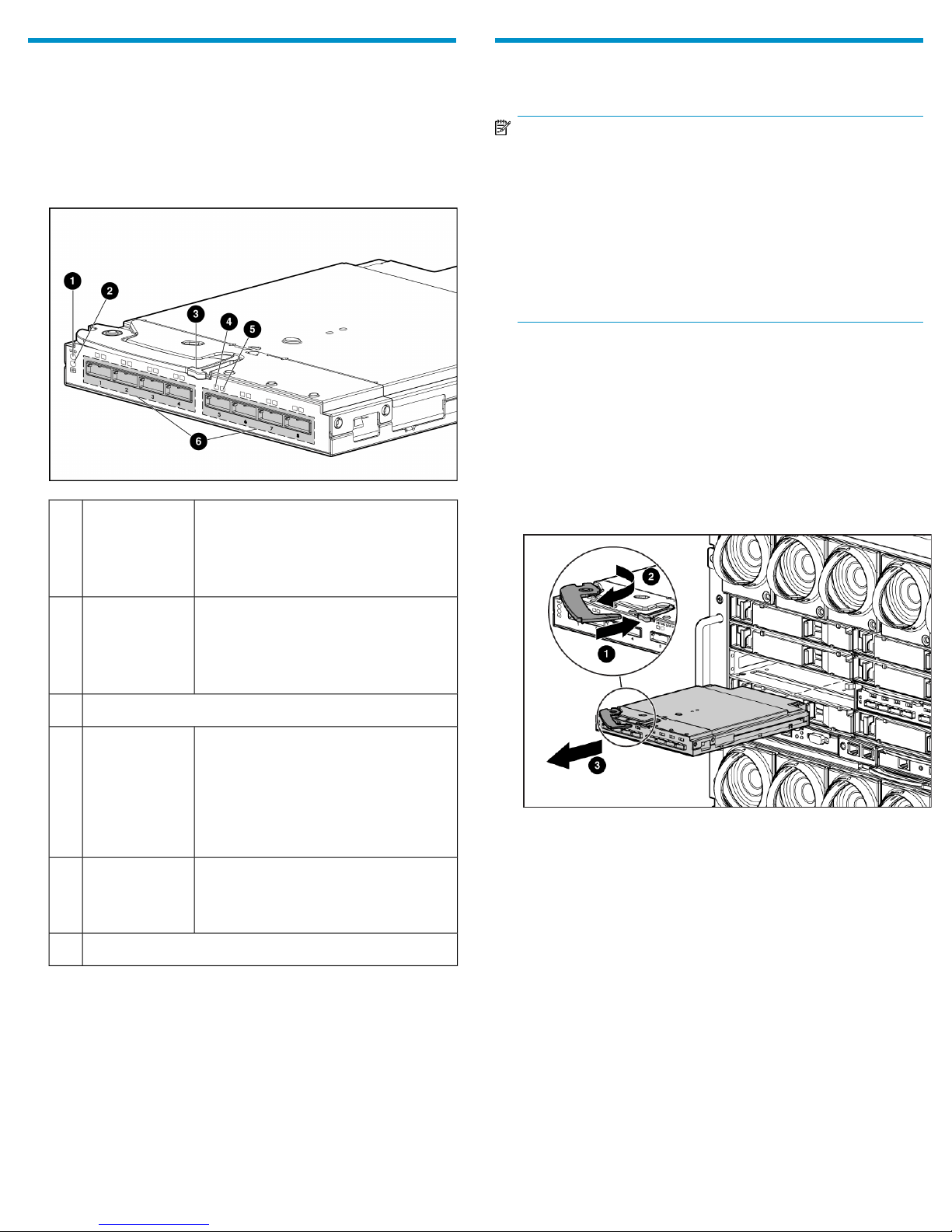
• Switch LEDs—View the Health, Link, and Fault LEDs for error patterns.
• Off—Normal
Unit ID LED1
• Solid blue—Being identified
• Blinking blue—Firmware is being up-
dated
Removing the failed switch
NOTE:
• In redundant-switch environments, the 3Gb SAS Switch may
be hot-replaced in an operational enclosure.
• In single-switch environments, all activity through the switch
must be halted prior to the replacement.
• The 3Gb SAS Switch does not have a power on/off button.
Power is automatically applied or removed when the switch
is installed or removed from the enclosure. Alternatively, power
can be applied or removed through the Onboard Administrator
application.
For illustration purposes, the following images demonstrate removing a
3Gb SAS BL Switch in interconnect bay 5 of a BladeSystem c7000
enclosure.
1. Stop all traffic through the failed or failing switch.
2. Use Onboard Administrator to shut down the switch. (Optional, but
a best practice.)
3. Disconnect all cables from the failed switch, making sure to label
each cable with its port number to facilitate re-connection.
4. Remove the failed switch.
• Off—Not powered up
Health LED2
• Solid green—Healthy
• Blinking amber—Error, there is a
problem with the switch
Release button for the locking latch handle.3
• Off—No link between the server and
storage
Link LED4
Fault LED5
SAS ports (to external storage)6
• Solid green—Link between server and
storage is established
• Blinking green—Activity on the estab-
lished link
• Off—Normal
• Amber—Link error, there is a problem
with the port
nl
nl
nl
nl
nl
nl
nl
nl
nl
nl
nl
nl
nl
Page 2
 Loading...