

Page 1

HP StorageWorks
300 Virtual Lib
rary System user guide
AH138-96002
Part number: AH1 38–96002
irst edition edition: November 2006
F
Page 2

Legal and notice information
© Copyright 2006 Hewlett-Packard Development Company, L.P.
The information contained herein is subject to change without notice. The only warranties for HP products and services are set forth
in the express warranty statements accompanying such products and services. Nothing herein should be construed as constituting
an additional warranty. HP shall not be liable for technical or editorial errors or omissions contained herein.
Page 3

Contents
Aboutthisguide .......................... 11
Relateddocumentation.................................... 11
Documentconventionsandsymbols ............................. 12
Rackstability ....................................... 13
HPtechnicalsupport.................................... 13
Subscriptionservice .................................... 14
OtherHPwebsites .................................... 14
HP-authorizedreseller ................................... 14
1Introduction............................ 15
Features ......................................... 15
Benefits ....................................... 15
Systemstatusmonitoring ................................ 16
Redundancy ..................................... 16
Components ....................................... 16
2 Hardware installation ...................... 19
Preparingfortheinstallation................................. 19
PreparetheEVAfortheVLS300............................. 19
Toolsforinstallation .................................. 19
TakingESDprecautions................................. 19
Groundingmethodstopreventelectrostaticdischarge.................... 20
Unpacking ........................................ 20
Removingthepackingmaterials ............................. 20
Rackplanningresources .................................. 20
Rackrequirements..................................... 21
Rackwarnings ...................................... 21
Optimumenvironment ................................... 21
Space and airflowrequirements ............................. 21
Temperaturerequirements................................ 22
Powerrequirements .................................. 22
Electricalgroundingrequirements ............................ 23
Identifyingtheshippingcartoncontents............................ 23
VLS300systemshippingcarton ............................. 23
InstallingtheVLS300nodesintoarack............................ 25
Installrailsintherack ................................. 25
AttachrailstotheVLS300(appliance) .......................... 26
Installapplianceinrack ................................ 27
Installthe100MbEthernetswitch2524intoarack....................... 27
Installthe1GbEthernetswitch2824intoarack........................ 28
Installrailsforswitch2824intherack .......................... 28
Attachrailstothe2824switch.............................. 29
Installswitch2824inrack................................ 30
InstallingVLS300cables .................................. 30
3Multi-nodesetup ........................ 35
Configureprimarynode—node0 .............................. 35
Configurethesecondarynode(s)—nodes1through7...................... 35
HP StorageWorks
3
Page 4

4Storageconfiguration ...................... 37
EstablishingcommunicationbetweentheVLS300andtheEVA.................. 37
Verifyingarrayzoning ................................. 37
PresentingtheLUNs .................................. 37
ManagingVLS300capacity................................. 40
DiscoveringarrayLUNs................................. 40
DeletingarrayLUNs.................................. 41
Configuringstoragepools................................ 42
Destroyingstoragepools ................................ 44
Installingcapacitylicenses ................................. 45
5Operation ........................... 47
PoweringontheVLS300system ............................... 47
Rebootingthesystem.................................... 47
Poweringoffthesystem................................... 48
6Userinterfaces . . ........................ 51
Userinterfacerequirements ................................. 51
CommandViewVLS.................................... 51
Windowregions.................................... 52
OpeningaCommandViewVLSsessionfromawebbrowser................. 53
OpeningaCommandViewVLSsessionfromCommandViewTL ............... 54
Installing the SSL certificateintoyourwebbrowser ..................... 54
RestartingCommandViewVLS ............................. 57
ClosingaCommandViewVLSsession .......................... 58
Secureshellandserialuserinterfaces............................. 58
Openingasecureshellsession ............................. 58
Closingasecureshellsession .............................. 59
Openingaserialsession ................................ 59
Closingaserialsession................................. 59
7Configuration........................... 61
Settingthenetworksettings ................................. 61
SettingthenetworksettingsusingtheVLSdiscoveryutility .................. 61
SettingthenetworksettingsusingtheCLIcommandset ................... 63
SettingthenetworksettingsusingCommandViewVLS ................... 64
Settingtheuserpreferences................................. 65
EditingthedefaultFChostportsettings............................ 66
Enablinganddisablingoversubscription ........................... 67
ManagingvirtualdeviceLUNs................................ 68
DefaultLUNnumbering................................. 69
OperatingsystemLUNrequirementsandrestrictions..................... 69
LUNmasking..................................... 69
LUNmapping..................................... 70
Dualportvirtualdevices ................................ 71
Creatingavirtuallibrary .................................. 72
Creatingtapedrives.................................... 75
Creatingcartridges .................................... 77
Destroyingavirtuallibrary ................................. 80
Destroyingatapedrive................................... 81
Destroyingcartridges.................................... 82
Addingandremovingbarcodetemplates ........................... 84
8Management.......................... 87
Changingtheaccountpasswords .............................. 87
Managinghighavailability................................. 88
Arraydualpathing................................... 88
4
Page 5

Loadbalancing .................................. 88
LUNpathfailover ................................. 89
PrivateLANdualpathing................................ 91
Managingcartridges.................................... 91
Unloadingacartridgefromadrive.............................. 94
Freeingupstoragespace.................................. 94
RestartingVLSdeviceemulations............................... 94
Updating the software . . . . . . . . . . . . . . . . . . . . . . . . . . . . . . . . . . . 95
Saving con figurationsettings ................................ 96
9Monitoring........................... 99
Statusinformationinthestatuspane ............................. 99
Statusicons........................................ 99
Devicestatusicon ................................... 99
Navigationtreeicon.................................. 100
Notificationalerts ..................................... 100
CommandViewVLS.................................. 101
E-mail notification ................................... 102
EditingtheE-mailserversettings........................... 102
EdittheE-mailsettings ............................... 103
SNMP notification................................... 104
EditingtheSNMPsettings.............................. 104
Trace log files....................................... 105
Viewing trace log files ................................. 105
Saving a trace log file ................................. 105
Creatingasupportticket ................................ 106
10CLIcommandset........................ 107
Commands........................................ 107
Conventions ..................................... 107
CLI-onlycommands .................................... 107
Connectioncommands................................. 107
Outputcommands................................... 108
VLScommands ...................................... 108
Network settings configurationcommands......................... 108
Configurationcommands................................ 109
Managementcommands................................ 114
Monitoringcommands ................................. 115
11 C o m p o n e n t i d e n t i fication .................... 119
VLS300nodecomponents,LEDs,andbuttons ......................... 119
Frontpanelcomponents ................................ 119
FrontpanelLEDsandbuttons .............................. 119
Rearpanelcomponents................................. 121
Systemboardcomponents ............................... 121
SystemboardLEDs................................... 122
NodeLEDsandinternalhealthLEDcombinations...................... 123
Fanmodulelocations.................................. 125
ProcessorzonefanmoduleLED ............................. 125
Switch2524components.................................. 126
Switch2824components.................................. 126
USBLANadaptercomponents................................ 127
12Componentreplacement..................... 129
Safetyconsiderations.................................... 129
Preventingelectrostaticdischarge............................. 129
Groundingmethodstopreventelectrostaticdamage .................... 129
HP StorageWorks
5
Page 6

Warningsandcautions................................. 129
Preparationprocedures................................... 130
ExtendingaVLS300nodefromtherack ......................... 130
RemovingtheVLS300nodeaccesspanel......................... 131
InstallingtheVLS300nodeaccesspanel ......................... 131
VLS300nodecomponentreplacement ............................ 132
SATAharddrive.................................... 132
CD-ROMdrive .................................... 132
Powersupply ..................................... 133
Powersupplyzonefanmodule.............................. 134
Processorzonefanmodule ............................... 135
DIMM........................................ 136
Processor....................................... 137
Replacingaprimarynode ............................... 139
Replacingasecondarynode .............................. 140
Switch2524replacement.................................. 141
Switch2824replacement.................................. 141
USBLANadapter..................................... 141
13 Disaster recover y . ....................... 143
RecoveringfromanodeRAIDvolumefailure.......................... 143
Restoring the configurationsettings............................ 143
Restoring the virtual library configuration from a configuration file............. 143
Rebuilding the virtual library configuration....................... 144
RecreatingtheVLS300storagepools......................... 145
Re-installingtheVLScapacitylicenses........................... 145
Recoveringfromoperatingsystemfailure ........................... 145
ATroubleshooting......................... 147
Commonissues ...................................... 147
BRegulatorycompliancenotices .................. 151
Regulatory compliance identificationnumbers ......................... 151
Batterystatement ..................................... 151
FederalCommunicationsCommissionnotice.......................... 152
FCCratinglabel.................................... 152
ClassAequipment................................. 152
ClassBequipment................................. 152
Declaration of Conformity for products marked with the FCC logo, United States only . . . . . . 152
Modification ..................................... 153
Cables........................................ 153
Canadiannotice(AvisCanadien) .............................. 153
ClassAequipment................................... 153
ClassBequipment................................... 153
EuropeanUnionnotice................................... 153
Japanesenotices ..................................... 154
Koreannotices ...................................... 154
ClassAequipment................................... 154
ClassBequipment................................... 154
Taiwanesenotices..................................... 155
BSMIClassAnotice.................................. 155
Taiwanbatteryrecyclestatement............................. 155
Lasercompliance ..................................... 155
Dutchlasernotice ................................... 156
Frenchlasernotice................................... 156
Germanlasernotice.................................. 156
Italianlasernotice................................... 157
Japaneselasernotice ................................. 157
6
Page 7

Spanishlasernotice .................................. 157
Recyclingnotices ..................................... 158
Disposal of waste equipment by users in private household in the European Union . . . . . . . . 158
Dutchnotice ..................................... 158
Czecholslovakiannotice ................................ 158
Estoniannotice .................................... 159
Finnishnotice..................................... 159
Frenchnotice ..................................... 159
Germannotice .................................... 159
Greeknotice ..................................... 160
Hungariannotice ................................... 160
Italiannotice ..................................... 160
Latviannotice..................................... 161
Lithuaniannotice ................................... 161
Polishnotice ..................................... 161
Portuguesenotice ................................... 162
Slovakiannotice.................................... 162
Sloveniannotice.................................... 162
Spanishnotice .................................... 163
Swedishnotice .................................... 163
Batteryreplacementnotices................................. 164
Dutchbatterynotice .................................. 164
Frenchbatterynotice.................................. 164
Germanbatterynotice ................................. 165
Italianbatterynotice.................................. 165
Japanesebatterynotice................................. 166
Spanishbatterynotice ................................. 166
CSpecifications ......................... 167
VLSnode......................................... 167
Switch2824 ....................................... 168
Switch2524 ....................................... 169
Environmental specifications................................. 169
Glossary............................. 171
Index .............................. 177
HP StorageWorks
7
Page 8

Figures
1
2
3
4
5
6
7
8
9
10
11
12
13
14
15
16
17
18
19
20
21
22
23
24
25
26
27
28
29
30
31
32
33
34
35
36
37
38
39
40
41
42
43
44
..Installrails................................... 26
..Removeslidesfromrails............................. 26
..AttachingrailstotheVLS300node ........................ 27
..Switch2524mountingbrackets.......................... 28
..Switch2824railinstallation,front......................... 29
..Switch2824railinstallation,back ........................ 29
..Attach rai
..Primarynodeports............................... 31
..Secondarynodeports.............................. 32
..Switch2824ports ............................... 33
..Switch2524ports ............................... 34
..Notificationswindow.............................. 35
..AddNodeWizardwindow ........................... 36
..FibreChanneldetailswindow .......................... 37
..Add a Hos
..AddaHostPortwindow............................. 39
..VdiskActiveMemberPropertieswindow...................... 40
..StorageLUNsdetailswindow .......................... 41
..UnpresentHost(s)window............................ 42
..ConfirmDestroyStoragePoolwindow....................... 44
..Identitytabwindow............................... 46
..RestartHeadWizardwindow .......................... 48
..ShutdownHeadWizardwindow......................... 49
..CommandViewVLSloginwindow ........................ 53
..SecurityAlertwindow.............................. 55
..Certificatewindow............................... 56
..Cert
..RestartCommandViewVLSwindow ....................... 58
..VLSdiscoveryutility–mainwindow........................ 62
..VLS discovery utility – Device Con
..Set Network ConfigurationWizardwindow .................... 65
..UserPreferenceswindow ............................ 66
..FCHostPortswindow.............................. 67
..Chassisdetailswindow ............................. 68
..HostLUNMappingModewindow ........................ 70
.. LibraryParameters–MapLUNswindow ..................... 71
..CreateVirtualLibraryWizardwindow(1of12)................... 72
..CreateVirtualLibraryWizardwindow(2of12)................... 73
reateVirtualLibraryWizardwindow(3of12)................... 74
..C
..CreateVirtualLibraryWizardwindow(4of12)................... 74
..CreateVirtualLibraryWizardwindow(5of12)................... 75
..CreateVirtualLibraryWizardwindow(6of12)................... 76
..CreateVirtualLibraryWizardwindow(7of12)................... 77
..CreateVirtualLibraryWizardwindow(8of12)................... 78
lstoswitch2824............................ 30
twindow .............................. 38
ificateImportWizardwindow ........................ 57
figurationwindow................. 63
8
Page 9

45
..CreateVirtualLibraryWizardwindow(9of12)................... 79
46
..CreateVirtualLibraryWizardwindow(10of12) .................. 79
47
..CreateVirtualLibraryWizardwindow(11of12) .................. 80
48
..CreateVirtualLibraryWizardwindow(12of12) .................. 80
49
..Virtuallibrarydetailswindow .......................... 81
50
..Tapedrivedetailswindow............................ 82
51
..Cartridges
52
..Cartridgesparameterswindow.......................... 84
53
..Add/RemoveBarcodeTemplateswindow ..................... 85
54
..EditAccountswindow.............................. 87
55
..StorageLUNswindow ............................. 89
56
..FixPrimaryPathsWizardwindow......................... 90
57
..Notificationswindow.............................. 90
58
..CartridgeDetailswindow ............................ 92
59
..CartridgesParameterswindow.......................... 93
60
..RestartEmulationswindow............................ 95
61
..Software Update window . . . . . . . . . . . . . . . . . . . . . . . . . . . . 96
62
..Save Configurationwindow ........................... 97
63
..Devicestatusiconinthestatusbanner....................... 100
detailswindow............................ 83
64 ..Navigationtreeicon .............................. 100
65
..Notificationalertexamples ........................... 100
66
..Notificationswindow.............................. 101
67
..Edit Ma
68
..EditEmailSettingswindow ........................... 103
69
..EditSNMPSettingswindow ........................... 104
70
..LogViewerwindow............................... 105
71
..SupportTicketwindow ............................. 106
72
..Slidingthenodeoutoftherack.......................... 131
73
..Removinganodeharddrive........................... 132
74
..EjectingtheCD-ROMdrive............................ 133
75
..Removinganodepowersupply ......................... 133
76
..InstallinganACpowersupply .......................... 134
77
..Placingthepowercordinthestrainreliefclip.................... 134
78
..Removingthenodepowersupplyzonefanmodule ................. 135
79
..Rem
80
..RemovingthenodeDIMM............................ 136
81
..Liftingtheprocessorretainingcard ........................ 137
82
..Releasingtheprocessorretainingclipsandliftlockinglever.............. 138
83
..Removingtheprotectivecoverfromtheprocessor .................. 138
84
..Aligningtheprocessorpinswiththesocketholes .................. 139
85
..Closingtheprocessorlockingleverandretainingclips................ 139
86
..Railreleasebracket............................... 140
87
..Re
ilServerSettingswindow......................... 102
ovingtheprocessorzonefanmodule ..................... 136
store Configwindow ............................. 144
HP StorageWorks
9
Page 10

Tables
1
2 ..VLS300capacity................................ 17
3
4
5
6
7
8
9
..Documentconventions.............................. 12
..VLS user inte
..CLIconnectioncommands............................ 107
..CLIoutputcommands.............................. 108
..CLI network settings configurationcommands.................... 109
..CLI configurationcommands........................... 110
..CLImanagementcommands........................... 115
..CLImonitoringcommands............................ 116
rfaces ............................... 51
10
Page 11

About this guide
This user guide provides information to help you:
• Become familiar with HP StorageWorks 300 virtual library system (VLS) features, models, and
components
• Install and operate your VLS
• Configure your VLS to meet the data backup needs of your environment
• Manag e your VLS so that it continues to meet the data backup needs of your environment
• Monitor your VLS hardware status
• Replace failed customer-replaceable components
• Perform disaster recovery
• Troubleshoot configuration problems
“About this Guide” topics include:
• Related documentation
• Document conventions and symbols
•Rackstability
• HP technical support
•Subscriptionservice
• Helpful web sites
• the section called “HP-authorized reseller”
Related documentation
HP provid
• HP StorageWorks 300 virtual library system release notes
• HP StorageWorks 300 virtual library system user guide
• HP Stora
See the D
documentation.
es the following documentation to support this product:
geWorks 300 virtual library system solutions guide
ocumentation CD provided with the VLS and our web site (h
ttp://www.hp.com)forrelated
HP StorageWorks
11
Page 12

Document conventions and symbols
Table 1 Document conventions
Convention
Blue text: Table 1
Blue, underlined text: http://
www.hp.com
Bold text
Italic text Text emphasis
Monospace text
Monospace, italic text
Monospace, bold text
WARNI
Indic
NG!
ates that failure to follow directions could result in bodily harm or death.
Element
Cross-referen
Web site addresses
• Keys that are pressed
• Text typed into a GUI element, such as
abox
• GUI elements that are clicked or
selected, such as menu and list items,
buttons, tabs, and check boxes
• File and directory names
• System output
• Code
• Commands, their arguments, and
argument values
• Code variables
• Command variables
Empha
ce links and E-mail addresses
sized monospace text
CAUTION:
Indicates that failure to follow directions could result in damage to equipment or data.
NOTE:
Provides additional information.
The following equipment symbols may be found on hardware to which this guide pertains. They have
the following meanings:
WARNING!
These symbols, which mark an enclosed surface or area of the equipment, indicate the
presence of electrical shock hazards. The enclosed area contains no operator serviceable parts.
WARNING: To reduce the risk of injury from electrical shock hazards, do not open this enclosure.
12
About this guide
Page 13
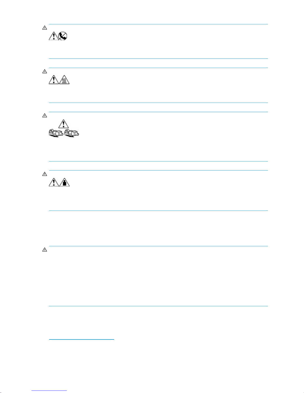
WARN ING!
These symbols, which mark an RJ-45 receptacle, indicate a network interface connection.
WARNING: To reduce the risk of electrical shock, fire, or damage to the equipment, do not plug
telephone or telecommunications connectors into this receptacle.
WARN ING!
These symbols, which mark a surface or area of the equipment, indicate the presence of a hot
surface or hot component. Contact with this surface could result in injury.
WARNING: To reduce the risk of injury from a hot component, allow the surface to cool before touching.
WARN ING!
Power supplies or systems marked with these symbols indicate the presence of multiple
sources of power.
WARNING: To reduce the risk of personal i njury from electrical shock, remove all power cords to
completely disconnect power from the power supplies and systems.
WARN ING!
Any product or assembly marked with these symbols indicates that the component exceeds the
recommended weight for one individual to handle safely.
WARNING: To reduce the risk of personal injury or damage to the equipment, observe local
occupational health and safety requirements and guidelines for manually handling material.
Rack stability
Rack stability protects personnel and equipment.
WARN ING!
To reduce the
• The leveling jacks are extended to the floor.
• The full weight of the rack rests on the leveling jacks.
• In single ra
• In multiple rack installations, the racks are coupled.
• Only one rack component is extended at any time. A rack may become unstable if more than one
rack compo
riskofpersonalinjuryordamagetotheequipment,besurethat:
ck installations, the stabilizing feet are attached to the rack.
nent is extended for any reason.
HP technical support
Telephone numbers for worldwide technical support are listed on the following HP web site:
h
ttp://www.hp.com/support/. From this web site, select the country of origin.
HP StorageWorks
13
Page 14

NOTE:
For continuous quality improvement, calls may b e recorded or monitored.
Be sure to have the following information available before calling:
• Technical support registration number (if applicable)
• Product serial numbers
• Product model names and numbers
• Applicable error messages
• Operating system type and revision level
• Detailed, specificquestions
Subscription service
HP strongly recommends that customers register online using the Subscriber’s choice web site:
1. Access h
2. Click the Subscribe link near the bottom of the screen.
3. Click the Business & IT Professionals link.
4. Click the Driver and Support aler ts link.
5. Click [edit] on the Product ownership task bar to add and delete products.
Subscribing to this service provides you with E-mail updates on the latest product enhancements, newest
driver versions, and firmware documentation updates as well as instant access to numerous other product
resources.
ttp://www.hp.com.
Other HP web sites
For additional information, see the following HP web sites:
•h
ttp://www.hp.com
•http://www.hp.com/go/storage
•http://www.hp.com/service_locator
•http://www.docs.hp.com
HP-authorized reseller
For the name of your nearest HP authorized reseller:
• In the United States, call 1-800-345-1518
• In Canada, call 1-800-263-5868
• Elsewhere, see the HP web site for locations and telephone numbers: h
ttp://www.hp.com.
14
About this guide
Page 15

1Introduction
This section describes the HP StorageWorks 300 virtual library system features and models.
Features
The HP StorageWorks 300 virtual library system (VLS) is a RAID disk-based SAN backup device that
emulates physical tape libraries, allowing you to perform disk-to-virtual tape (disk-to-disk) backups using
your existing backup application(s). The many benefits of performing data backups to a VLS instead of
physical tape are described in Benefits.
The VLS emula
libraries. Y
of tape drives and cartridges included in each tape library to meet the needs of your environment. You
configure the size of the virtual cartridges in your VLS, which provides even more flexibility.
The VLS accommodates mixed IT platform and backup application environments, allowing all your servers
and backup applications to access the virtual media simultaneously. You can specify which servers
are allowed to access each virtual library and tape drive you configure. You can change the default
LUNs assigned to the virtual library and tape drives for each host as needed to accommodate different
operating
tes a variety of physical tape libraries, including the tape drives and cartridges inside the
ou determine the number and t ypes of tape libraries a VLS emulates, and the number and type
system requirements and restrictions.
Benefits
Data stor
using a backup application.
Integrating a VLS into your existing storage and backup infrastructure delivers the following benefits:
• Faster backups
• Faster single file restores
• Lower operating costs
• More efficient use of storage space
• Reduced risk of data loss and aborted backups
ed on a VLS is easily cloned to physical tape for off-site disaster protection or long-term archival
BackupspeedsarelimitedbythenumberoftapedrivesavailabletotheSANhosts. TheVLS
emulates many more tape drives than are available in physical tape libraries, allowing more hosts
to run backups concurrently.
The VLS is optimized for backups and delivers faster performance than a simple disk-to-disk solution.
Asinglefile can be restored much faster from disk than tape.
Fewer physical tape drives and cartridges are required as full backups to tape are eliminated. Also,
fewer cartridges are required as small backups stored on multiple virtual cartridges can be copied to
one physical cartridge.
Physical tape libraries cannot share storage space with other physical tape libraries, and physical
cartridges cannot share storage space with other physical cartridges. This unused storage space
is wasted.
Storage space is not wasted in a VLS, because VLS storage space is dynamically assigned as it is
used. Storage space is shared by all the libraries and cartridges configured on a VLS.
RAID-basedstorageismorereliablethantapestorage.
Aborted backups caused by tape drive mechanical failures are eliminated.
HP StorageWorks
15
Page 16

Sy stem status monitoring
VLS hardware, e
monitored by th
Anotification alert is generated by the VLS software when a ha rdware or environmental failure is detected
or predicted. VLS notification alerts are displayed on Command View VLS, and can also be sent as mail
to the mail addresses you specify and/or SNMP traps to the m anagement consoles you specify.
For more information about viewing VLS hardware status, and/or receiving VLS notification alerts by
mail or as SNMP
Redundancy
The VLS includes some important redundancy features:
• Redundant fans
Each node includes redundant fans. If a fan fails in a node (head unit), the remaining fans run at
a faster speed, temporarily providing enough cooling.
• Redundant power supply
Each node includes a redundant power supply. With redundant power supplies, if one power
supply fails in a node, the remaining functional power supply provides enough power for the
node to function. HP recommends that the primary power supplies be connected to a separate
powersourceatthesitefromtheredundantpowersupplies.
CAUTION:
Replace a failed fan or power supply as soon as possible to maximize the life expectancy of the
remaining fan(s) or power supply and to maintain redundancy.
nvironmental, and virtual d evice (library, tape drive, cartridge) status is constantly
e VLS software and displayed on the VLS web user interface, Command View VLS.
traps, see Monitoring.
• Redundant system disks
Each VLS node (head unit) contains two system hard drives configured into a RAID 1 (mirrored)
volume. This provides dual boot capability and quick recovery if one of the system hard drives fail.
For more information about VLS features, visit the H P web site: h
Components
A VLS300 consists of at least two nodes (one primary node and between one and seven secondary
nodes) and dual LAN switches for internal inter-node connections. See the drawing of racked nodes
below. Each node contains dual processors, two dual port FC HBAs, four 512 MB memory modules,
and two 80 Gb hard drives.
No external storage is included with the VLS300; instead, the gateway uses external storage in existing
arrays.
ttp://www.hp.com
16
Introduction
Page 17
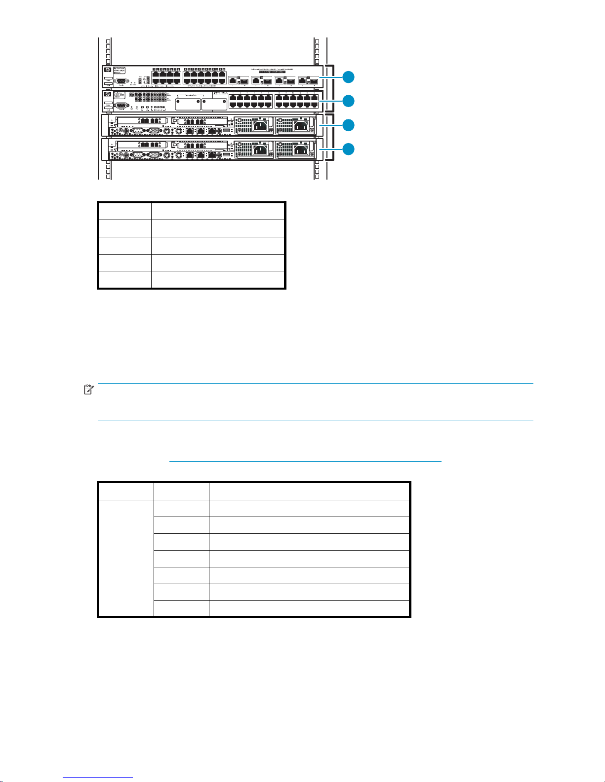
1
Item
1
2
3
4
26
Description
Ethernet switch 2824 (1 Gb)
Ethernet switch 2524 (100 Mb)
Node 0, primary node
Node 1, secondary node
2
3
4
11149
The two nodes include a base license to configure up to 25 LUNs—ten LUNs per gateway node plus five
2 TB upgrade licenses—which gives the gateway up to 50 TB capacity.
Up to six nodes can be added to a VLS300 for a total of eight nodes in a single gateway. Each
additional node adds licenses for up to ten more LUNs and increases maximum external capacity by up
to 20 TB. Capacity can also be increased by purchasing capacity bundles, each of which adds licensing
for one additional external array LUN and increases maximum external capacity by up to 2 TB.
NOTE:
Maximum capacity for each LUN on the VLS300 is 2 TB.
Adding nodes and licenses increases the VLS300 storage capacity as shown in Table 2. Adding nodes
also increases the performance. See the HP StorageWorks VLS300 Virtual Library System Quickspec on
the HP web site (h
ttp://h18006.www1.hp.com/products/storageworks/6000vls) for performance data.
Table 2 VLS300 capacity
Model Nodes Maximum capacity without expansion LTUs
VLS300
250TB
370TB
4
5
6130TB
7
8170TB
90 TB
11 0 T B
150 T B
HP StorageWorks
17
Page 18

18
Introduction
Page 19

2 Hardware installation
This section details the steps to install the VLS hardware:
• Preparing for the installation
• Unpacking
• Id entifying the VLS shipping carton contents
• Installing the VLS node(s) into a rack
• Install the 100 Mb Ethernet switch 25 24 into a rack
• Install the 1 Gb Ethernet switch 2824 into a rack
• Installing VLS300 cables
Preparing for the installation
PreparetheEVAfortheVLS300
Arrays that will be connected to the VLS300 must already be setup with the appropriate configuration
as described in the solutions guide, including:
• Command View EVA is installed, at firmware revision 5100 or later, and functioning properly.
• There are either two external FC switches/fabrics or two zones on an external FC switch/fabric so that
there are two (high availability) data pathways from the VLS300 to the EVA.
• All of the required VRaid LUNs required for the VLS have been created on the EVA according to the
design g uidelines (for example, each LUN is roughly the same size—2 TB is preferred. The LUNs can
not be read-only. RAID 5 is recommended. Path failover is balanced across both EVA controllers).
If this has not been done, refer to the solutions guide for instructions.
Tools for installation
• Two p eople
• Phillips screwdriver
• Box cutt
ing knife
Taking ESD precautions
To prevent damaging the system, be aware of the precautions you need to follow when setting up the
system or handling parts. A discharge of static electricity from a finger or other conductor may damage
system boards or other static-sensitive devices. This type of damage may reduce the life expectancy of
the device.
To prevent electrostatic damage:
• Avoid hand contact by transporting and storing products in static-safe containers.
• Keep electrostatic-sensitive parts in their containers until they arrive at static-free workstations.
• Place parts on a grounded surface before removing them from their containers.
• Avoid touching pins, leads, or circuitry.
• Always be properly grounded when touching a static-sensitive component or assembly.
HP StorageWorks
19
Page 20

Grounding metho
ds to prevent electrostatic discharge
Several method
installing electrostatic-sensitive parts:
• Use a wrist strap connected by a ground cord to a grounded workstation or computer chassis.
Wrist straps are flexible straps with a minimum of 1 megaohm ±10 percent resistance in the
ground cords.
• Use heel straps, toe straps, or boot straps at standing workstations.
Wearthestrapsonbothfeetwhenstandingonconductivefloors or dissipating floor mats.
• Use conductive field service tools.
• Use a portabl
If you do not h
install the part.
For more information on static electricity or assistance with product installation, contact your authorized
reseller.
s are used for grounding. Use one or more of the following methods when handling or
To provide proper ground, wear the strap snug against the skin.
e field service kit with a folding static-dissipating work mat.
ave any of the suggested equipment for proper grounding, have an authorized reseller
Unpacking
Place the shipping carton as close to the installation site as possible. Before unpacking the VLS, inspect
the shipping carton for damage that may have occurred during shipment. If you detect any damage,
notify the carrier and HP before unpacking the unit.
Removing the packing materials
To unpack the VLS:
1. Open the t
2. Carefull
3. Place th
NOTE:
Inspect
detected, contact your authorized service representative.
4. Remove the accessory kits and documentation from the shipping cartons. Set them aside for later use.
5. Place shipping materials back into the shipping cartons.
6. Set the shipping cartons aside for later use.
op of the shipping cartons.
y lift the units out of the boxes and remove the packing materials.
eunitsonastableworksurface.
the units for any damage that may have occurred during shipment. If damage is
Rack planning resources
The rack resource kit ships with all HP or Compaq branded 9000, 10000, and H9 series racks. A
summary of the content of each resource follows:
• Custom Builder is a web-based service for configuring one or many racks. Rack configurations
can be created using:
•Asimple,guidedinterface
• Build-it-yourself model
• The Installing Rack Products video provides a visual overview of operations required for
configuring a rack with rack-mountable components. It also provides the following impor tant
configuration steps:
• Planning the site
20
Hardware installation
Page 21

• Installing rack servers and rack options
•Cablingserversinarack
• Coupling multiple racks
• The Rack Products Documentation CD enables you to view, search, and print documentation for
HP and Compaq branded racks and rack options. It also helps you set up and o ptimize a rack
in a manner that best fits your environment.
Rack requirements
HP supports the HP System E racks and the HP 10000 Series racks for use with VLS systems. Other racks
might also be
suitable, but have not been tested with the VLS.
Rack warnings
WARN ING!
To reduce the risk of personal injury or damage to the equipment, be sure that:
• The leveling jacks are extended to the floor.
• The full weight of the rack rests on the leveling jacks.
• The stabilizing feet are attached to the rack if it is a single-rack installation.
• The racks are coupled together in multiple-rack installations.
• Only one component is extended at a time. A rack may become unstable if more than one
component is extended for any reason.
WARN ING!
To reduce the risk of personal injury or equipment damage when unloading a rack:
• At least two people are needed to safely unload a rack from a pallet. An empty 42U rack can weigh
as much as 115 kg (253 lb), can stand more than 2.1 m (7 ft) tall, and may become unstable when
being moved on its casters.
• Never stand in front of a rack when it is rolling down the ramp from the pallet. Always handle a
rack from both sides.
Optimum environment
When installing a VLS in a rack, select a location that meets the environmental standards described
in this section and Environmental specifications.
Space and airflow requirements
To allow for servicing and adequate airflow, observe the following space and airflow requirements
when deciding where to install a rack:
• Leave a
• Leave a minimum clearance of 76.2 cm (30 in) behind the rack.
• Leave a minimum clearance of 122 cm (48 in) from the back of the rack to the back of another
rack w
A VLS draws in cool a ir through the front door and expels warm air through the rear door. Therefore, the
front and rear rack doors must be adequately ventilated to allow ambient room a ir to enter the cabinet,
and the rear door must be adequately ventilated to allow the warm air to escape from the cabinet.
minimum clearance of 122 cm (48 in) in front of the rack.
hen racks are back-to-back.
HP StorageWorks
21
Page 22

CAUTION:
To prevent improper cooling and damage to the equipment, do not block the ventilation openings.
When vertical space in the rack is not filled by a VLS or rack component, the gaps between the
components cause changes in airflow through the rack and across the servers. Cover all gaps with
blanking panels to maintain proper airflow. Using a rack without blanking panels results in improper
cooling that can lead to thermal damage.
The Compaq 10000 Series racks provide proper VLS cooling from flow-through perforations in the front
and rear doors that provide 64 percent open area for ventilation.
CAUTION:
If a third-party rack is used, observe the following additional requirements to ensure adequate airflow
and to prevent damage to the equipment:
• Front and rea
5,350 sq cm (
(equivalent to the required 64 percent open area for ventilation).
• Side—The clearance between the installed rack component and the side panels of the rack must
be a minimum
r doors—If the 42U rack includes closing front and rear doors, you must allow
830 sq in) of holes evenly distributed from top to bottom to permit adequate airflow
of 7 cm (2.75 in).
Temperature requirements
To ensure continued safe and reliable equipment operation, install or position the system in a
well-ventilated, climate-controlled environment.
The maximum recommended ambient operating temperature (TMRA) for the VLS system is 35° C (95° F).
The temperature in the room where the rack is loca ted must not exceed 35° C (95° F).
CAUTION:
To reduce the risk of damage to the equipment when installing third-party options:
• Do not permit optional equipment to impede airflow around the VLS or to increase the internal rack
temperature beyond the maximum allowable limits.
• Do not exceed the TM RA.
Power requirements
Installation of a V LS must comply with local and regional electrical regulations governing the installation
of information technology equipment by licensed electricians. This equipment is designed to operate in
installations covered by NFPA 70, 1999 Edition (National Electric Code) and NFPA-75, 1992 (code for
Protection of Electronic Computer/Data Processing Equipment). For electrical power ratings on options,
see the product rating label or the user documentation supplied with that option.
WARNING!
To reduce the risk of personal injury, fire, or damage to the equipment, do not overload the AC supply
branch circuit that provides power to the rack. Consult the electrical authority having jurisdiction over
wiring and installation requirements of your facility.
22
Hardware installation
Page 23

CAUTION:
Protect the VLS from power fluctuations and temporary interruptions with a regulating uninterruptible
power supply (UPS). This device protects the hardware from damage caused by power surges and
voltage spikes and keeps the system in operation during a power failure.
When installing a VLS connected to more than one disk array, you may need to use additional power
distribution devices to safely provide power to all devices. Observe the following guidelines:
• Balance the device power load between available AC supply branch circuits.
• Do not allow the overall system AC current load to exceed 80 percent of the branch circuit
AC current rating.
• Do not use common power outlet strips for this equipment.
• Provide a separate electrical circuit for each device.
Electrical grounding requirements
The V LS must be grounded properly for proper operation and safety. In the United States, you must install
the equipment in accordance with NFPA 70, 1999 Edition (National Electric Code), Article 250, as well
as any local and regional building codes. In Canada, you must install the equipment in accordance
with Canadian Standards Association, CSA C22.1, Canadian Electrical Code. In all other countries,
you must install the equipment in accordance with any regional or national electrical wiring codes, such
as the International Electrotechnical Commission (IEC) Code 364, parts 1 through 7. Furthermore, you
must be sure that all power distribution devices used in the installation, such as branch wiring and
receptacles, are listed or certified grounding-type devices.
Because of the high ground-leakage currents associated with multiple VLS and servers connected to the
same power source, HP recommends the use of a power distribution unit (PDU) that is either permanently
wired to the building’s branch circuit or includes a non-detachable cord that is wired to an industrial-style
plug. NEMA locking-style plugs or those complying with IEC 60309 are considered suitable for this
purpose. Using c ommon power outlet strips for a VLS is not recommended.
Identifying the shipping carton contents
Unpack the VLS shipping cartons and locate the materials and d ocumentation necessary for installing the
VLS. All the rack mounting ha rdware and documentation necessary for installing a VLS node into a rack
is included in the node shipping carton. All the rack mounting hardware and documentation necessary
for installing a VLS disk array into a rack is included in the disk array shipping carton.
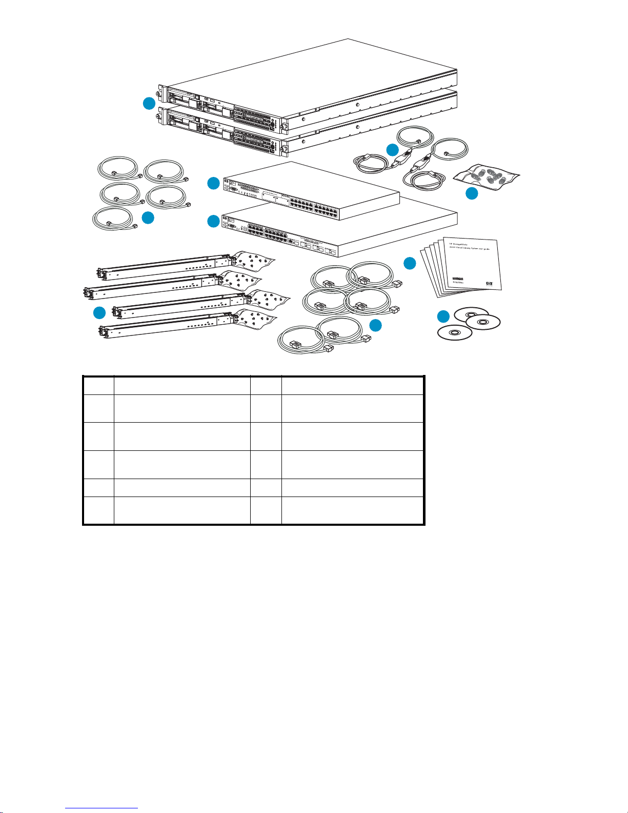
VLS300 system shipping carton
NOTE:
In addition to the contents of the shipping carton(s) and an existing EVA, you will also need a #1 Phillips
screwdriver , a #2 Phillips screwdriver , 1 Ethernet cable to connect to the existing external network, and 4–8 FC
cables to connect from the nodes to the external FC fabri cs/switches. These are not included with the VLS300.
HP StorageWorks
23
Page 24
1
10
5
Item
1
2
3
4
5
2
4
3
Description
VLS300 Gateway primary and
secondary nodes
100 Mb Ethernet switch 2524
(1)
1GbEthernetswitch2824(1)
3ftEthernetcables(5)
1U rack mounting hardware kits
and documentation (3)
Item
6
7
8
9
10
2
6
6
Description
Power co rds (6)
Documentation CD (1) and VLS
Quick Restore CDs (2)
Printed VLS node installation
poster (1)
Loopback plugs
USB LAN adapters (2)
9
8
7
11145
24
Hardware installation
Page 25
Installing the
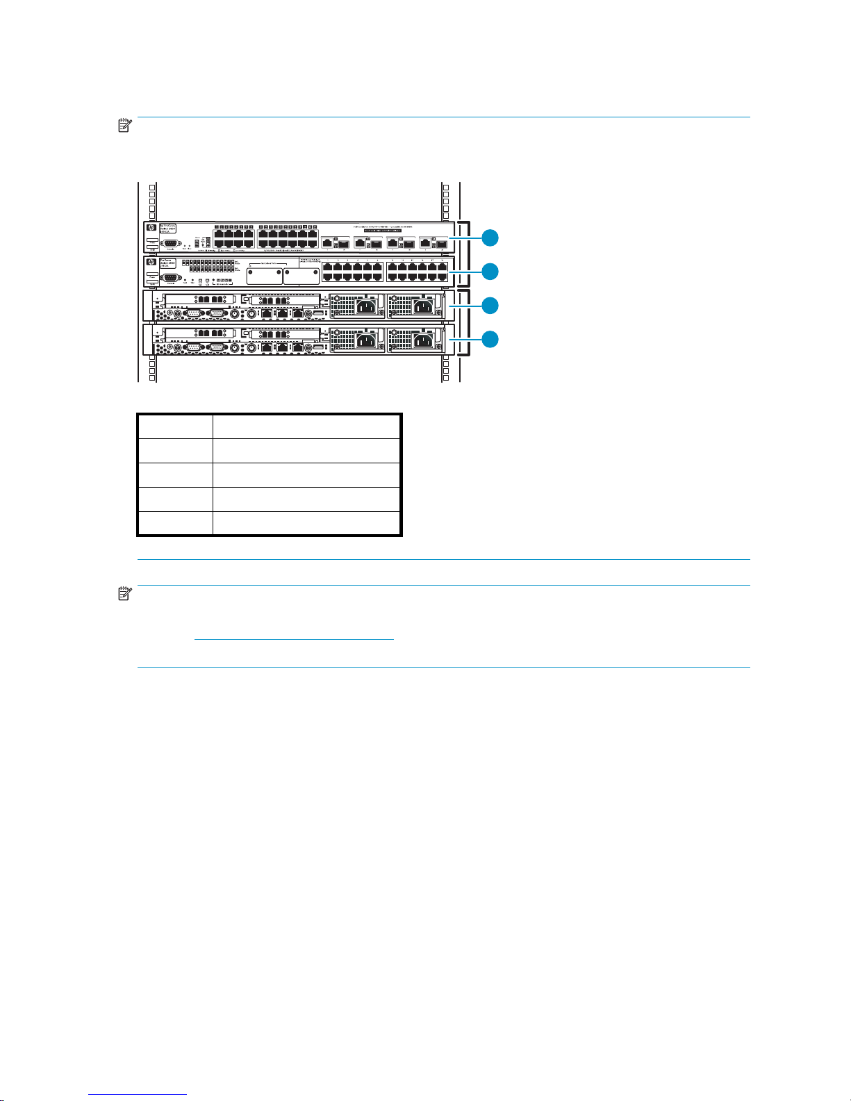
NOTE:
The components of the VLS300 are connected with 3 ft. cables. Install the components close enough in
the rack to accommodate the cable lengths. HP recommends the racking configuration:
VLS300 nodes into a rack
1
Item
1
2
3
4
26
Descripti
Ethernet switch 2824 (1 Gb)
Ethernet switch 2524 (100 Mb)
Node 0, primary node
Node 1, secondary node
on
2
3
4
11149
NOTE:
If you are installing the node into a telco rack, order the appropriate option kit at the RackSolutions.com
web site: h
ttp://www.racksolutions.com/hp. Follow the instructions on the web site to install the rack
brackets.
To install a node into the rack involves three main tasks:
• Install rails in the rack
• Attach rails to the VLS (appliance)
• Install appliance in rack
Instal
lrailsintherack
1. Locate the appropriate rail kit—part number 361190-B21.
2. Instal
l the two slide rails to the sides of the rack.
a. Adjust the side rail assemblies to the approximate rack depth.
b. At one side of the rack, align the rail holes with the holes in the rack and secure with the
ded mounting hardware using a #2 Phillips screwdriver.
provi
HP StorageWorks
25
Page 26
5201b
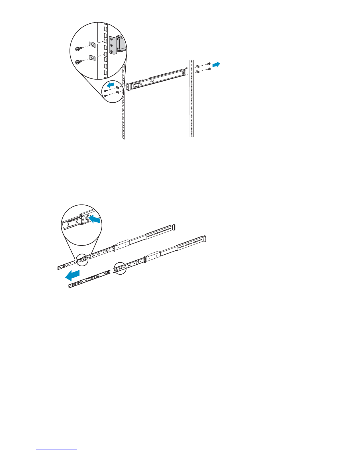
Figure 1 Install rails
c. Repeat these tasks for the rail on the other side of the rack.
3. Remove the inner slide rails from the outer slide rails. To do so, extend the inner slide rails from the
front of the rack until they lock in place. Then press the inner rail release latch (see Figure 2)and
pull the inner slide rails straight out.
10685A
Figure 2 Remove slides from rails
Attach rails to the VLS300 (appliance)
To attach the rails to the appliance:
1. Align the rail with the node so that the word “FRONT” on the rail is seen right-side-up and at the
front of the node.
26
Hardware installation
Page 27
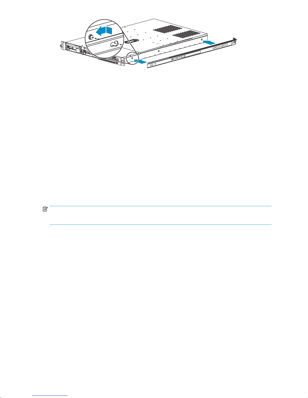
Figure 3 Attaching rails to the VLS300n ode
2. Align the holes in the rail with the round tabs on the side of the node.
3. Put the rail onto the node with the tabs extending into the holes on the side of the rail, then slide the
railtowardthefrontofthenodeuntilthetabsarelockedintotherail.
4. Perform these steps again to Install the other rail on the other side of the node.
Install appliance in rack
1. Align the rails on the appliance with the rails in the rack.
2. Slidetheappliancefullyintotherack.
The rails
3. With the appliance fully seated in the rack, tighten the thumbscrews just until the node bezel is
secured to the rack.
on the appliance will lock into the rails on the rack.
Install the 100 Mb Ethernet switch 2524 into a rack
To install the 100 Mb Ethernet switch 2524 into the rack:
NOTE:
There are no rails associated with this switch.
11184
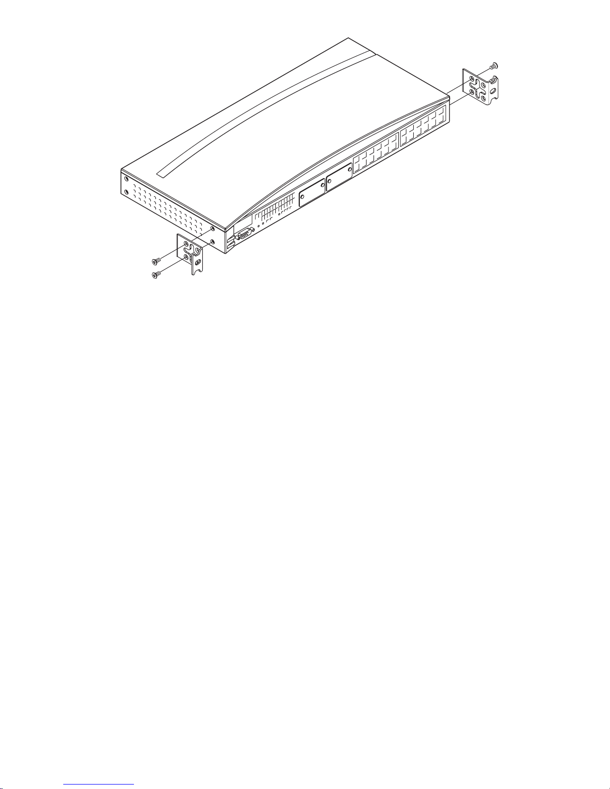
1. If the metal mounting brackets are not attached to the switch, at tach them now.
a. Align the brackets so that the four screw holes are ag ainst the side of the switch and the side
of the bracket with the single screw hole extends from the switch and a ligns with the front of
the bezel. See Figure 4.
HP StorageWorks
27
Page 28
11192
Figure 4 Switch 2524 mounting brackets
b. Adjust alignment so that the holes in the side of the mounting bracket line up with the holes in
the switch.
c. Use a #1 Phillips (cross-head) screwdriver and the four M4 screws (included) to attach the
mounting brackets to the switch.
2. Placetheswitchontopofnode0intherack.
3. Align the holes of the mounting brackets on both sides of the switch’s bezel with the holes in the rack.
4. On each side of the switch, insert a Phillips screw through the holes in the mounting bracket and into
the holes in the rack.
5. Tighten the Phillips screws to secure the switch to the rack.
6. Connect the power cable to the front of the switch, run the cable through the holes in the rack to the
back of the rack but do not connect the cable to a PDU at this time.
Insta
ll the 1 Gb Ethernet switch 2824 into a rack
To install a node into the rack involves three main tasks:
• Install rails for switch 2824 in the rack
•Atta
• Install switch 2824 in rack
ch rails to the 2824 switch
Installrailsforswitch2824intherack
1. Locate the correct rail kit—part number 356578–B21.
2. Install the two slide rails to the sides of the rack.
a. Locate four of the MS screws and insert each one into a square, semi-pierced washer (included).
b. At one side of the rack, align the front rail holes with the holes in the back of the rack Secure by
inserting two of the provided MS screws and semi-pierced washers through the two outermost
holes in th e rail and into the rack (see Figure 5).
28
Hardware installation
Page 29
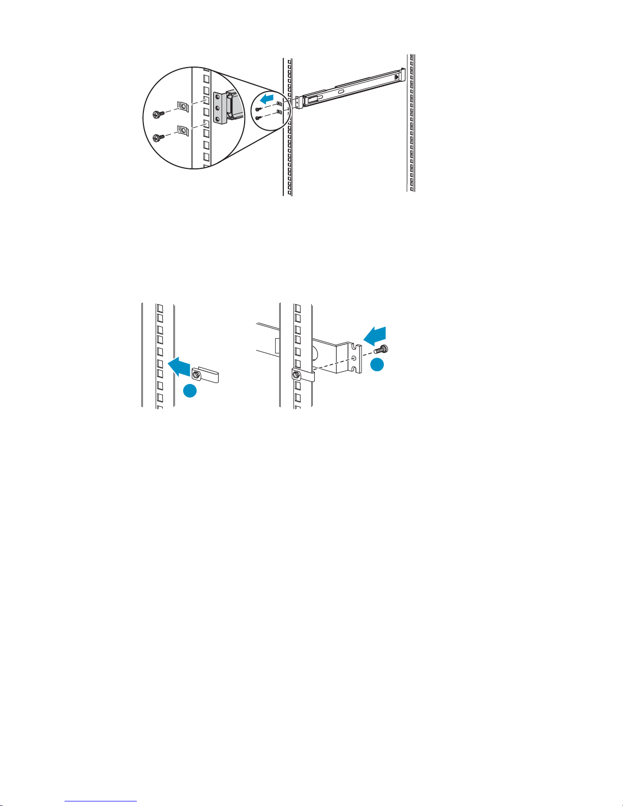
11194
Figure 5 Switch 2824 rail installation, fron t
c. At the front of the rack, slide the clip onto the rack so that the hexagonal hole i s facing out
and align the holes in the clip with the proper hole in the rack. Then align the rail hole with
these holes.
2
1
11195
Figure 6 Switch 2824 rail installation, back
d. Push the screw through the rail, clip, and rack, then into the nut. Tighten the screw to secure
the rail to the rack (see Figure 6).
e. Repeat these tasks for the rail on the other side of the rack.
Attach rails to the 2824 switch
To attach the rails to the 2824 switch:
1. Align th
but is p
two hol
e inner rail with the switch so tha t the p erpendicular screw hole faces away from the switch
arallel to the switch bezel (face-plate). The two holes at the front of the rail must align with the
es at the front of the switch (see Figure 7).
HP StorageWorks
29
Page 30

11193
Figure 7 Attach rails to switch 2824
2. Insert two of the pan-head screws through the slide rail and into the switch at the front of the
switch. Tighten the screws.
3. Insert two of the pan-head screws through the appropriate holes in the slide rail and into the switch
at the back of the switch. Tighten the screws.
4. Perform these steps again to Install the other rail on the other side of the node.
Install sw
itch 2824 in rack
1. Align the rails on the appliance with the rails in the rack.
2. Slidetheappliancefullyintotherack.
The rails
3. On each side of the switch, insert an MS screw through the holes in the rail and into the holes
in the rack.
4. Tighten
on the appliance will lock into the rails on the rack.
theMSscrewstosecuretheswitchtotherack.
Installing VLS300 cables
To install VLS300 cables, follow the instructions below.
1. On the primary node of the VLS300:
30
Hardware installation
Page 31

1 2 3 4
10 11
5
1
Dual port FC ca
2
Dual port FC card, host port, port 1
3
Dual port FC card, storage port, port 3
4
Dual port FC card, storage port, port 2
5
Serial port to access CLI
6
Monitor and keyboard
7
NIC1, on pri
8
NIC2, on primary node connects to port 1 of switch 2824
9
USB port, connects to USB/Ethernet adapter, then to port 1 of switch 2524
10
Power supply 2
11
Power supply 1
6789
11148
rd, host port, port 0
mary node only connects to the customer-provided external network (array)
Figure 8 Primary node ports
a. Connect one end of an Ethernet cable (not included) to NIC1. Connect the other end of the
cable to t
b. Connect
he existing external network.
one end of an FC cable (not provided) to host port 0. Connect the other end to an
external FC switch/fabric that connects to your tape backup hosts.
c. If desired, connect one end of an FC cable (not provided) to host port 1. Connect the other end
to an ext
ernal FC switch/fabric that connects to your tape backup hosts. Otherwise, connect a
loopback plug to host port 1.
d. Connect one end of an FC cable (not provided) to device port 3. Connect the other end to an
external FC switch/fabric that connects to your external array.
e. Connec
t one end of an FC cable (not provided) to device port 2. Connect the other end to a
second external FC switch/fabric that connects to your external array.
f. Connecttotheserialport(cableisprovided)toaccessthecommand-lineuserinterfaceatinitial
uration. Also connect to this during debug activities. Disconnect from this port during
config
normal operations.
NOTE:
You must connect to the keyboard and monitor ports when performing Quick Restore
(keyboard and monitor not included).
g. Connect one end of an Ethernet cable to NIC2. Connect the other end of the cable to port
1 of Switch 2824 (see Figure 1 0).
h. Connect one end of a USB cable to the USB port. Connect the other end of the cable to the
USB/Ethernet adapter. Connect an Ethernet cable to the Ethernet end of the adapter, then
connect the Ethernet cable to port 1 of Switch 2524 (see Figure 11).
i. Connect a power cable to each power supply and to a PDU. If possible, connect each power
supply to a separate PDU to provide redundancy.
HP StorageWorks
31
Page 32

j. Begin routing the cables through the cable ties that shipped with the racks.
2. On the secondary node(s) of the VLS300:
NOTE:
Use this procedure to install any secondary node—node 1 which is shipped with the
gateway or upgrade nodes 2–7 which can be ordered separately.
1 2 3 4
5 6
1
2
3
4
5
6
7
8
Dual port FC card, host port, port 0
Dual port FC card, host port, port 1
Dual port FC card, storage port, port 3
Dual port FC card, storage port, port 2
NIC2, on secondary nodes connects to the next available port of switch 2824
USB port, connects to USB/Ethernet adapter
Power supply 2
Power supply 1
78
11153
Figure 9 Secondary node ports
a. Connect one end of an FC cable (not provided) to host port 0. Connect the other end to an
external FC switch/fabric that connects to your tape backup hosts.
b. If desired, connect one end of an FC cable (not provided) to host port 1. Connect the other end
to an external FC switch/fabric that connects to your tape backup hosts. Otherwise, connect a
loopback plug to host port 1.
c. Connect one end of an FC cable (not provided) to device p ort 3. Connect the other end to an
external FC switch/fabric that connects to your external array.
d. Connect one end of an FC cable (not provided) to device port 2. Connect the other end to a
second external FC switch/fabric that connects to your external array.
e. Connect one end of an Ethernet cable to NIC2. Connect the other end of the cable to port
2 of Switch 2824 (see Figure 1 0).
f. Connect one end of a USB cable to the USB por t. Connect the other end of the cable to the
USB/Ethernet adapter. Connect an Ethernet cable to the Ethernet end of the adapter, then
connect the Ethernet cable to port 2 of Switch 2524 (see Figure 11).
g. Connect a power cable to each power supply on the node a nd to a PDU. If possible, connect to
separate PDUs to provide redundancy.
h. Continue routing the cables through the cable ties that shipped with the racks.
32
Hardware installation
Page 33

NOTE:
For each additional node, connect cables from NIC2 and the USB port to the next available
ports on both switches. For example, connect the 3rd node to switch ports 3, connect the
4th node to switch ports 4, etc.
3. On Switch 2824:
1 3 5 7
2 4 6 8 9
1
Ethernet cable from NIC2 of primary node
2
Ethernet cable from NIC2 of 2nd node
3
Ethernet cable from NIC2 of 3rd node (if present)
4
Ethernet cable from NIC2 of 4th node (if present)
5
Ethernet cable from NIC2 of 5th node (if present)
6
Ethernet cable from NIC2 of 6th node (if present)
7
Ethernet cable from NIC2 of 7th node (if present)
8
Ethernet cable from NIC2 of 8th node (if present)
9
Ethernet cable from port 24 of switch 2524
11147
Figure 10 Switch 2824 ports
a. Ensure that the Ethernet cables from the NIC2 ports of each node are firmly set in the
appropriate ports.
b. Connect one end of an Ethernet cable to por t 24 of Switch 2824. Connect the other end of
the Ethernet cable to port 24 of Switch 2524.
c. Connect a power cable to the front of the switch, run the cable through the holes in the rack to
the back of the rack, then connect the cable to a PDU.
d. Continue routing the cables through the cable ties that shipped with the racks.
4. On Switch 2524:
HP StorageWorks
33
Page 34

1 2 3 4 5 6
26
7 8 8
11146
1
2
3
4
5
6
7
8
9
Ethernet cable from USB adapter on primary node
Ethernet cable from USB adapter on 2nd node
Ethernet cable from USB adapter on 3rd node (if present)
Ethernet cable from USB adapter on 4th node (if present)
Ethernet cable from USB adapter on 5th node (if present)
Ethernet cable from USB adapter on 6th node (if present)
Ethernet cable from USB adapter on 7th node (if present)
Ethernet cable from USB adapter on 8th node (if present)
Ethernetcablefromport24ofswitch2824
Figure 11 Switch 2524 ports
a. Ensure that the power cable is connected to the switch, as described in the racking instructions
(see Installing the VLS node(s) into a rack).
b. Ensure that the Ethernet cables from the NIC2 ports of each node are firmly set in the
appropriate ports on the switch.
c. Ensure that the Ethernet cable from port 24 of Switch 2524 is firmly connected to port 24
of Switch 2824.
d. Route the power cable through the holes in the rack to the back of the rack, then connect
the cable to a PDU.
e. Finish routing the cables through the cable ties that shipped with the racks.
The VLS300 system hardware installation is complete. Continue installation by configuring the identities
of each node.
34
Hardware installation
Page 35

3 Multi-node setup
After the VLS300 is physically installed, configure the identities of each node:
•Configure primary node--node 0
•Configure the secondary node(s)—nodes1 through 7
Configure primary node—node 0
To configure the primary node:
1. On the primary node, connect to the serial port or use the keyboard and mouse ports to connect to
aconsole.
2. Power on the primary node of the VLS300.
After several minutes, a menu will appear on your monitor asking whether the node is a primary
(master, m) o
3. Enter “m”. The VLS300 will then run cable checks and configuration checks.
4. Afterthechecksarecompletethenodewillrebootautomatically. Waitfortheprimarynodeto
fully boot.
Rebooting
completed
the login prompt on the terminal (Figure 1 2).
r secondary (slave, s) node.
is complete when you receive the “Initializing node#”, then “Initializing for node#
.” messages in the systems notifications (if you have DHCP enabled) or when you see
Figure 12 Notifications window
5. Set the IP a ddress and other public network configurations on the VLS300. Refer to Setting the
network settings for instructions.
Config
ure the secondary node(s)—nodes 1 through 7
figure the secondary nodes (nodes 1 through 7):
To con
1. On the secondary node, connect to the serial port or use the keyboard and mouse ports to connect
to a console.
HP StorageWorks
35
Page 36

2. Power on the primary node and all previously installed secondary nodes of the VLS300.
3. Power on the secondary node being added to the VLS300.
After several minutes, a menu will appear on your monitor asking whether the node is a primary
(master, m) or secondary (slave, s) node.
4. Enter “s”.
5. At the prompt, enter the node number (next sequential node number).
The VLS300 will then run cable checks and configuration checks, then reboot automatically.
6. Once the new secondary node has finished rebooting, log on to Command View VLS.
7. Select the System tab.
8. Select Nodes from the navigation tree.
9. Select Add Node from the task bar in the main window. This will bring up the Add Node Wizard.
10. VerifythatthenodenameintheNode Name field is the next available number that you configured
previously (Figure 1 3). For example, the primary node, previously configuredasNode0,isidentified
as Node 0 in the list of nodes on the navigation tree. The first secondary node added should be
Node 1. The next secondary node added should be Node 2.
Figure13AddNodeWizardwindow
11 . Select Finish to add the node.
12. Repea
t these steps to add nodes until all of the nodes are listed in the navigation tree.
NOTE:
Node numbering must be sequential with no gaps. Gaps in ID numbering will prevent the VLS300 from
recognizing any nodes with an ID after the gap. For example, if node numbering is 0, 1, 2, 4, 5,
the VLS300 will not recognize nodes 4 and 5.
36
Multi-node setup
Page 37

4Storageconfiguration
After all of the nodes have been c on figured, configure the storage:
• Establishing communication between the VLS300 and the EVA
• Managing VLS300 capacity
• Installing capacity licenses
Establishing
communication between the VLS300 and the EVA
Verifying array zoning
Verify that you have configured the zoning between the EVA por ts and all storage ports on all the nodes
of your VLS300. For example, storage ports 2 and 3 on each node should connect to different SAN
zones/fabrics; EVA controllers should also be connected to both zones/fabrics. If you have not done
so, refer to the VLS solutions guide to do so now.
Presenting the LUNs
1. Gather the device WWPNs.
a. From Command View VLS, select the System tab.
b. From the N
The statu
(WWPNs) (Figure 1 4).
s pane displays information about the FC ports including the world wide port names
avigation Tree, select Nodes,thenaspecific node, then Fibre Channel.
Figure 14 Fibre Channel details window
c. Write down the WWPN for each storage port on the node. There is no need to write down the
WWPNs for the host ports.
d. Repeat these steps for each node on the VLS300.
2. Create a host entry for the VLS device using the W WPNs gathered in the previous step:
HP StorageWorks
37
Page 38

a. Access Command View EVA.
b. From the Storage tab navigation tree, select the EVA storage system that will be used for the
VLS300, then Hosts.
c. In the status pane, click on Add Host to display the AddaHostscreen.
d. Enter the Host name (preferably the VLS hostname), enter or select one of the WWPNs (noted
in the previous step) in the Port WW Name box on the VLS300, and select Linux for the Host
OS (Figure 15).
NOTE:
If a WWPN is not in the Port WW Name box, there may be a zoning error. After
creating the host entries, verify that your zoning is correctly configured.
Figure 15 Add a Host window
e. Click on Add H ost.
f. From the Storage tab navigation tree, select the host you just added.
g. Click on the Ports tab in the status pane.
h. Click on Add port ,selectoneoftheVLS300WWPNs(notedinthepreviousstep)fromthe
pull-down list or type one of the appropriate W W PNs, then click Add port (Figure 16).
38
Storage configuration
Page 39

Figure 16 Add a Host Port window
i. Continue to add ports until all of the ports on the VLS300 are added and are listed on the Host
Properties screen in the status pane.
3. Present the LUNs:
CAUTION:
Present only the disks that you wish to use with the VLS300 because existing data will be
destroyed during storage pool configuration.
a. In Command View EVA, in the Storage tab navigation tree, select the EV A for the VLS300 storage
system, Virtual Disks, the disk name that you want to present, then ACTIVE under that disk.
b. Select the Presentation tab.
c. Ensure that Write Protect is set to No.
d. Ensure that the Preferred path/mode is set to either Path A-Failover only or Path B-Failover
only (Figure 17).
NOTE:
Set the Preferred path/mode forhalfofthediskstoPath A-Failover only,andtoPath
B-Failover only for the other half of the disks. This balances the data trafficacross
both A and B controllers. For more information on data traffic balancing, see Array
dual pathing.
HP StorageWorks
39
Page 40

Figure 17 Vdisk Ac tive M ember Properties window
e. Click on Present, then select the VLS300 host (just created) on the Present Vdisk screen on
the status pane.
f. Click on Present Vdisk.
g. The Operation Succeeded message displays on the status pane. Click OK.
h. Repeat these steps for each disk to present to the VLS.
NOTE:
If needed, these disks can be unpresented. See To unpresent a LUN.Ifyouunpresenta
LUN, you must then reconfigure the LUN numbering for all LUNs on the VLS300 that
follow the unpresented LUN in sequential numbering.
Managing VLS300 capacity
There are several ways to manage the capacity of your system:
• Add external LUNs to the VLS300 configuration. See Discovering array LUNs.
• Delete external LUNs from the VLS300 configuration. See Deleting array LUNs.
• Create storage pools. See Configuring storage pools.
• Destroy storage pools. See Deleting array LUNs
• Enable device-side data compression when creating new tape drives. See Creating tape drives
Discovering array LUNs
1. Discover the LUNs, either by rebooting the entire VLS300 or:
a. Open a Command View VLS session and log in as the administrator. See Opening a Command
View VLS session from Command View TL.
b. In the Storage tab n avigation tree, select Storage LUNs.
c. Select Discover Unconfigured Storage from the task bar. This causes the VLS to recognize all
presented LUNs and return the following message: # storage lun(s) discovered. #
storage lun(s) deleted. At this point, the LUNs are still unconfigured.
2. Verify that the LUNs are properly assigned and that there are two data paths for each LUN.
40
Storage configuration
Page 41

a. Open a Command View VLS session and log in as the administrator. See Opening a Command
View VLS session from Command View TL.
b. In the Storage tab navigation tree, select Storage LUNs.
c. Under All, select All Nodes in the Nodes dialog box, then click View to display Storage LUN
Details and Storage LUN Details Per Node (Figure 18).
Figure 18 Storage LUNs details window
d. Ensure that all LUNs are listed under each node, and that each has a preferred and secondary
path.
NOTE:
IfaLUNisnotrecognizedbyeachnode,theLUNisunusable.PresenttheLUNtoany
node that does not yet recognize the LUN.
3. Resolve any errors, if necessary.
If there is a license violation, you can still view all the LUNs. Either install more licenses or remove the
LUNs that do not belong. This will eliminate the violation. See Deleting array LUNs.
Deleting array LUNs
To remove a LUN from the device:
1. Unpresent the LUN to the VLS (see instructions below) or delete the LUN from the external a rray.
2. Restart emulations or reboot the device (see Restarting the VLS device emulations or Rebooting
the system).
3. Discover unconfigured storage (see Discovering array LUNs). This deletes the removed LUNs
from the configuration.
To unpresent a LUN:
1. In Command View EVA, Storage tab navigation tree, select the EVA for the VLS300 storage
system, Virtual Disks, the disk name that you want to present, then ACTIVE under that disk.
2. Select the Presentation tab for the ACTIVE Vdisk.
3. Click on the Unpresent button.
HP StorageWorks
41
Page 42

4. Selectthedisktoremovefromthehost(Figure 19).
Figure 19 Unpresent Host(s) window
5. Click on Unpresent host(s).
6. Click OK from the confirmation dialog box.
7. Click OK under Operation Succeeded in the status pane.
8. If there is a break in numbering of the remaining LUNs, LUN numbers after the break must be
reconfigured. See Multi-node setup for detailed instructions.
CAUTION:
LUN numbering must be sequential with no gaps. Gaps in LUN numbering will prevent the VLS300
from recognizing any nodes with a ny LUNs after the gap. For example, if LUN numbering is 0, 1, 2,
4,5,theVLS300willnotrecognizeLUNs4and5.
Configuring storage pools
VLS auto creates the first storage pool, but you must create any additional pools. To do so:
NOTE:
The VLS300 can have either one storage pool for all LUNs, or one storage pool for each array. Refer to
thesolutionsguidefordetails.
42
Storage configuration
Page 43

1. Create a storage pool(s):
a. Open a Command View VLS session and log in as the administrator. See Opening a Command
View VLS session from Command View TL.
b. In the Storage tab navigation tree, select Storage Pools.
c. From the task bar, select Create Storage Pool.TheCreate Storage Pool Wizard is displayed.
d. Click Finish. CREATE STORAGE POOL COMPLETED is displayed.
e. Click Return.
f. If you a
re creating a separate storage pool for each array, repeat this process for each storage
pool.
2. Add the array LUNs to the storage pool(s).
a. Open a
View V
Command View VLS session and log in as the administrator. See Opening a Command
LS session from Command View TL.
b. In the Storage tab navigation tree, under Storage Pools, select a storage pool.
c. From the task bar, select Add External LUN.TheAdd External LUN Wizard is displayed.
NOTE:
This task does not appear if there are no licenses available.
d. From the list of available unconfigured LUNs, select the LUNs to add to the pool. (By default, all
LUNs are selected.)
NOTE:
View the WorldWideUniqueLunIDon the storage LUN list (on the System screen)
to identify which LUNs are associated with each array.
e. Use the Format check box to indicate whether the selected LUNs are initialized (formatted)
when added to the pool.
HP StorageWorks
43
Page 44

NOTE:
Do not format the LUNs when manually creating previously existing pools af ter
performing a disaster recovery of the primary node. If you do not format the LUN, all
cartridge data in that pool is retained.
f. Click Finish to add the LUNs to the pool.
The pool is now ready to have cartridges created.
NOTE:
If you created storage pools on a LUN that already contained cartridges, update the Allocated Capacity
numbers. To do this, select Cartridges from the system navigation pane, then select View for the All listing.
Destroying storage pools
Command View VLS allows you to destroy a specific storage pool or all storage pools.
NOTE:
Iftherearecartridgesinthepoolorpoolswhentheyaredestroyed,emulationswillrestart. Toavoidthis
restart, delete all cartridges from the pool prior to deleting the pool. (see Destroying cartridges).
To delete a single storage pool:
1. Open a Command View VLS session and log in as the administrator. See Opening a Command
View VLS session from Command View TL.
2. In the Storage tab navigation tree, select the pool to delete (listed under Storage Pools).
3. From the task bar, select Destroy Storage Pool.TheConfirm Destroy <storagepool name>
window is displayed (Figure 20).
Figure 20 Confirm Destroy Storag e Pool wind ow
4. Select Next to destroy the pool.
44
Storage configuration
Page 45

A second page of the Confirm Destroy <storagepool name> screen is displayed, containing the
following text: WARNING: Existing data in StoragePool # will be destroyed and cannot be recovered.
This step cannot be reversed.
5. Select Finish to display the screen c on firming that the storage pool has been destroyed.
6. Select Finish again to return to the system screen.
You can now either use the LUNs previously assigned to the destroyed pool in other pools, or
they can be deleted.
To delete all storage pools:
1. Open a Command View VLS session and log in as the administrator. See Opening a Command
View VLS session from Command View TL.
2. In the Storage tab navigation tree, select Storage Pools.
3. If you wish to destroy all storage pools, from the task bar, select Destroy All Storage Pools.The
Confirm Destroy All Storage Pools screen is displayed.
4. Select Next to destroy the pools.
Either recreate storage pools using the LUNs previously assigned to the destroyed pool(s), or delete
them.
Installing capacity licenses
A VLS capacity license must be installed on the VLS when storage exceeds the base license. If you are
in a license violation state, all VLS read/write operations are disabled until either sufficient licenses
are insta
LUNs are c
cleared a license violation by installing an upgrade capacity license, the VLS read/write operations are
automatically enabled without requiring a reboot.
lled to support the storage, or until excess storage is removed. Unconfigured VLS300 array
ounted by the system; therefore, they can contribute to license violation. When you have
NOTE:
See the
steps.
TheVLSnetworksettingsmustbesetbeforeacapacitylicensecanbeinstalled.SeeSetting the network
settings.
To install a capacity license on the VLS:
1. Install Command View TL.
2. Start Command View TL.
3. Complete the Command View TL initial configuration steps.
4. Add the VLS to Command View TL.
5. Open a Command View VLS session from Command View TL for the VLS. See Opening a Command
6. Click the Identity tab.
OpenView Command View for TL User Guide
HP
View VLS session from Command View TL.
The Identity tab window opens (Figure 2 1).
for instructions on performing the following
HP StorageWorks
45
Page 46

Figure 2 1
Identity tab window
7. Record the VLS serial number listed on the Identity tab window.
8. Obtain a license key from the HP web site (h
number a
nd license registration number.
ttp://www.webware.hp.com)usingtheVLSserial
NOTE:
Make sur
e to enter the VLS serial number correctly when obtaining the license key. If it
is entered incorrectly, the license key generated will not work and the license registration
number will become locked to the wrong serial number. If this occurs, contact HP Support
to obtain a new license registration number.
9. Add the license key to Command View TL.
Command View TL installs the license key on the VLS.
46
Storage configuration
Page 47

5Operation
This section describes how to power on and power off the VLS nodes. It is comprised of the following
topics:
• Powering on the VLS300 system
• Rebooting the system
• Powering off the system
Powering on t
To power on the VLS300 system:
1. Power on all arrays connected to the VLS300.
2. Power on the
3. Plug the VLS300 nodes’ AC power cords into a power source if not already connected.
4. Press the VLS300 secondary nodes’ Power On/Standby button. After the secondary nodes are
powering up, press the primary node’s Power On/Standby button. See Front panel LEDs and buttons.
5. Confirm that the VLS components are all functioning normally and the VLS is cabled correctly by
observing the condition of their status LEDs.
6. Rebooting the system is complete when you receive the “Initializing node#”, then “Initializing for
node# completed.” messages for all nodes in the systems notifications.
he VLS300 system
two private LA N switches connected to the VLS300.
Rebooting the system
To reboot the system:
To reboot from VLS CLI:
1. Verify that any backup or restore operation has completed and that the VLS is idle.
2. Open a secure shell session and log in as the administrator. See Opening a secure shell session.
3. Initiate a reboot of the VLS by entering:
restartSystem
To reboot from Command View VLS:
1. Verify that any backup or restore operation has completed and that the VLS is idle.
2. Open a Command View VLS session and log in as the administrator. See Opening a Command
View VLS session from a web browser.
3. Under the System tab, select Chassis in the navigation tree.
4. Under Maintenance Tasks,selectSystem Maintenance.
5. Select Restart All Nodes from the task bar.
Restart Head Wizard displays (Figure 22).
HP StorageWorks
47
Page 48

Figure 22 Restart Head Wizard window
6. Select Yes to reboot all nodes.
CAUTION:
Rebooting the VLS device places the VLS cartridges back into the same library slots and tape drives they
were in at the time of reboot. To move the cartridges from tape drives back into the appropriate slots, use
Force Unload fromthetaskbarvisiblewhenyouselectthetapedrivefromthenavigationtree.
Powering off the system
WARNING!
To reduce the risk of personal injury, electric shock, or damage to the equipment, remove
the power cord to remove power from the node before removing the access panel. The front panel Power
On/Standby button does not completely shut off system power. Portions of the power supply and some
internal circuitry remain active until AC power is removed.
To power off the system from the VLS CLI:
1. Verify that any backup or restore operation has completed and that the VLS is idle.
2. Open a s
erial session and log in as the administrator. See Opening a serial session.
3. Initia
4. If you will be removing the access panel from a node, wait until the VLS has completed its shutdown
5. Press the Power On/Standby button on all nodes to place the nodes in standby mode.
6. If you
48
te a shutdown of the VLS by entering:
shutdownSystem
ion, then press the UID LED but ton. See Front panel LEDs and buttons.
operat
Blue LEDs illuminate on the front and rear panels of the node.
When a
a. Go to the ba ck of the rack and locate the node by identifying the illuminated rear UID LED
b. Unpl
node activates standby power mode, the system power LED changes to amber.
will be removing the access panel from a node:
button.
ug the node AC power cords from the power source.
Operation
Page 49

The node is now without power.
To power off the system from Command View VLS:
1. Verify that any backup or restore operation has completed and that the VLS is idle.
2. Open a Command View VLS session and log in as the administrator. See Opening a Command
View VLS session from a web browser.
3. Under the System tab, select Chassis in the navigation tree.
4. Under Maintenance Tasks,selectSystem Maintenance.
5. Select Shutdown All Nodes from the task bar.
Shutdown H ead Wizard displays (Figure 23).
Figure 23 Shutdown Head Wizard window
6. Select Yes to shut down all nodes.
7. If you will be removing the access panel from a node, wait until the VLS has completed its shutdown
operation, then press the UID LED button. See Front panel LEDs and buttons.
Blue LEDs illuminate on the front and rear panels of the node.
8. Press the Power On/Standby button on all nodes to place the nodes in standby mode.
When a node activates standby power mode, the system power LED changes to amber.
9. If you will be removing the access panel from a node:
a. Go to the back of the rack and locate the node by identifying the illuminated rear UID LED
button.
b. Unplug the node AC power cords from the power source.
The node is now without power.
HP StorageWorks
49
Page 50

50 Operation
Page 51

6 Use r interfaces
This section describes the three user interfaces (UIs) that can be used to configure, manage, and monitor
the VLS over the web, remotely over the LAN, or through a serial connection. It also provides instructions
on how to open and close a connection to the VLS for each type of user interface. It is comprised
of the following topics:
• User interface requirements
• Command View VLS
• Secure shell and serial user interfaces
User interfa
Table 3 list
VLS should be used in most circumstances. It is the most intuitive and easiest to learn and use.
Multiple user interface sessions may be open at once.
Table 3 VLS us
User interface
Command View VLS PC or workstation
Secure shell (ssh) Secure shell client (such
ce requirements
s the VLS user interfaces and their requirements. Of the three user interfaces, Command View
er interfaces
Requirements
network attached to the
VLS node 0 running
Microsoft Internet
Explorer 6.0 or higher,
or Netscape Navigator
4.7 or higher
as PuTTY) network
attached to the VLS
node 0
Configuration
10/100/1000 BaseT
Ethernet port configured
with an appropriate IP
address, host name,
domain name, subnet
mask, and gateway
• Can login as
Administrator or
User.
10/100/1000 BaseT
Ethernet port configured
with an appropriate IP
address, subnet mask,
and gateway
• Can login as
Administrator only.
For more
information
See Command View
VLS.
See Secure sh ell and
serial user interfaces.
Serial Null-modem cable
attached to the VLS
node 0 and terminal
emulation program
(such as Windows
Hyperterminal)
configured to 115200
baud
Command View VLS
Command View VLS is a web browser-based GUI that you can use to configure, manage, and monitor
your VLS through a LAN. Command View VLS provides the following:
• Configuration and manag ement of VLS virtual devices (libraries and tape drives) and cartridges,
including LUN masking and LUN mapping
Only one serial
connection at a time is
permissible.
• Can login as
Administrator or
Emergency user.
See Secure sh ell and
serial user interfaces.
HP StorageWorks
51
Page 52

• Changing of the default FC host port settings
• Viewing and deleting VLS notification alerts
• Configuring VLS mail and SNMP notification alert settings
• Editing VLS account passwords
• Enabling and disabling storage capacity oversubscription
• Managing storage pools
• Viewing VLS hardware and virtual device status
• Installing VLS software updates
• Saving and restoring VLS network settings and virtual library configurations
• Restarting VLS device emulations and Command View VLS
• Viewing and saving VLS trace log files
Command View VLS is installed on the VLS and communicates through the LAN. Users can open a
Command View VLS session from a web browser on the LAN, HP StorageWorks Command View TL, or
HP Systems Insight Manager.
Window regions
Command View VLS windows consist of five regions. Not all regions are displayed on all windows.
1
2
3
4
5
Item
1
2
3
4
5
ption
Descri
status banner
task bar
spane
statu
notifications pane
navigation tree
NOTE:
You can
curso
enlargeorreduceanyregiononthewindow. Tochangethesizeofaregion,positionyour
r on the border of a pane, and press the left mouse button while simultaneously dragging the border.
52
User interfaces
Page 53

Opening a Comma
NOTE:
Before you can open a Command View VLS session, you must set the VLS network settings. See
Setting the network settings.
To open a Command View VLS session from a web browser:
1. Launch a web browser.
2. In the web browser URL box, enter:
https://<fully qualified name of the VLS>
NOTE:
Entering “http://<fully qualified name>” instead of the above URL
automatically redirects you to the secure “https://<fully qualified name>”
connection. All communications are over a secure connection.
3. If a Security Alert window opens and prompts you to accept the Secure Sockets Layer (SSL) certificate,
install the SSL certificate as described in Installing the SSL certificate into your web browser.
The first time you open a Command View VLS session (and the first time you open a Command View
VLS session after changing the fully qualified name of the VLS), a Security Alert window opens and
prompts you to accept the Secure Sockets Layer (SSL) certificate.
nd View VLS session from a web browser
Figure 24 Command View VLS login window
4. Enter ad
NOTE:
Logging
throughCommandViewVLS.Logginginasausergivesyouonlyviewingandcartridge
management privileges.
5. Enter the appropriate password in the Password box for the username entered.
ministrator or user in the Username box. The username is case sensitive.
in as administrator gives you full privileges to all VLS functions available
HP StorageWorks
53
Page 54

The default administrator password is admin.Thedefaultuserpasswordisguest.Thepassword
is case sensitive.
6. Click Login.
Opening a Command View VLS session from Command View TL
NOTE:
Before you can open a Command View VLS session from Command View TL, you must first install
Command View T
OpenView Command View for TL User Guide
Command View TL gives you the ability to manage and license multiple virtual and physical tape libraries
from a single m anagement application.
To open a Command View VLS session from Command View TL:
1. Start Command View TL.
2. From the Library Selection tab of the Launcher window, double-click the VLS from the list of libraries.
3. If a Security Alert window op ens and prompts you to a cce pt the Secure Sockets Layer (SSL) certificate,
install the SSL certificate as described in Installing the SSL certificate into your web browser.
The first time you open a Command View VLS session (and the first time you open a Command View
VLS session after changing the fully qualifi e d na m e of the VLS), a Security Alert window opens and
prompts you to accept the Secure Sockets Layer (SSL) certificate.
4. Enter administrator or user in the Username box. The username is case sensitive.
L on a PC or workstation and then add the VLS to Command View TL. See the
for instructions.
HP
NOTE:
LogginginasadministratorgivesyoufullprivilegestoallVLSfunctionsavailable
through Command View VLS. Logging in as a user gives you only viewing and cartridge
management privileges.
5. Enter the appropriate password in the Password box for the username entered.
The default administrator password is admin.Thedefaultuserpasswordisguest.Thepassword
is case sensitive.
6. Click Login.
Installing the SSL certificate into your web browser
The first time you open a Command View VLS session (and the first time you open a Command View VLS
session
you to a
Install the SSL certificate into your web browser:
1. Click Yes.
after changing the fully qualified name of the VLS), a Security Alert window opens and prompts
ccept the Secure Sockets Layer (SSL) cer ti ficate.
54
User interfaces
Page 55

Figure 25 Security Alert window
2. Click Install Certificate, and then click OK.
HP StorageWorks
55
Page 56

Figure 26 Certificate window
3. Select Automatically sel ect the certificatestorebasedonthetypeofcertificate, and then click Next.
56
User interfaces
Page 57

Figure 27
Certificate Imp o rt Wizard window
4. On the Ce
5. Continue to click OK or Finish on each window that displays until the Command View VLS login
window displays.
rtificate Store window, click Yes to add the certificate.
Restarting Command View VLS
To restart Command View VLS:
1. Under the System tab, select Chassis in the navigation tree.
2. Under Maintenance Tasks,selectSystem Maintenance.
3. Click Restart Command View VLS in the task bar.
The Restart Command View VLS window opens (Figure 28).
HP StorageWorks
57
Page 58

Figure 28 Restart Command View VLS window
4. Click Restart to confirm.
Closing a Command View VLS session
To close a C
ommand View VLS session, click Logout in the status banner or simply close the web browser.
Secure shell and seri al user interfaces
The secure shell user interface provides remote configuration and management of your V LS over a
LAN using the VLS comm a nd-line interface (CLI) comma nd set. The serial user interface provides local
configuration and manag em ent of your VLS through the serial connector on the rear of the VLS node 0
using the same VLS CLI command set.
A secure shell or serial session provides the following:
• Setting the VLS network settings
• Configuration and management of VLS virtual devices (libraries and tape drives) and cartridges
• Changing of the default FC host port settings
• Viewing and deleting VLS notification alerts
• Configuring VLS mail and SNMP notification alert settings
• Editing VLS account passwords
• Enabling and disabling storage capacity oversubscription
• Viewing VLS hardware status
• Saving and restoring VLS network settings and virtual library configurations
• Restarting VLS device emulations and Command View VLS
• Rebooting and powering off the VLS
The serial user interface also provides:
• Emergency login access that allows you to change the administrator password if it is forgotten.
Open
ing a secure shell session
NOTE:
Before you can open a secure shell session, you must set the VLS network settings. See Setting the
network settings.
58
User interfaces
Page 59

To open a secure shell session:
1. Open a secure shell session to the VLS using a secure shell program (such as PuTTY) or by entering:
ssh <fully qualified name of the VLS> and then press Enter.
2. At the Login as: prompt, enter administrator and then press Enter.
3. At the Password: prompt, enter the administrator password and then press Enter.
The default administrator password is admin.
Closing a secure shell session
To close a secure shell session:
Enter logout,
done, quit, bye,orexit and then press Enter.
Opening a serial session
To open a serial session:
1. Connect a PC or workstation to the serial connector on the rear of node 0 of the VLS using the
null-modem (serial) cable provided. See Rear panel components.
2. Establish a CLI session using a terminal emulation program, such as Windows Hyperterminal.
3. Enter administrator or emergency for username.
4. Enter the password for the username entered.
The default administrator password is admin. The emergency login password is repair.
NOTE:
Logging in as administrator or using the emergency login gives you full privileges to all VLS
functions available through the CLI command set.
Closing a serial session
To close a serial session, click Logout at the top of the Console Manager window. This logs you out of the
Console Manager and displays the Logon window.
HP StorageWorks
59
Page 60

60
User interfaces
Page 61

7Configuration
This section describes how to configure the VLS network settings, user preferences, FC host ports
(optional), virtual libraries, tape drives, and cartridges. It is comprised of the following topics:
• Setting the network settings
• Setting the user preferences
• Editing the default FC host port settings
• Enabling and disabling oversubscription
• Managing virtual device LUNs
• Creating a virtual library
•Creatingtapedrives
• Creating cartridges
• Destroying a virtual library
• D estroying a tape drive
• Destroying cartridges
• Adding and removing ba rcode templates
Setting th
enetworksettings
Before you
settings can be set using either the VLS discovery utility (see Setting the network settings using the VLS
discovery utility) or the CLI command set using the serial user interface (see Setting the network settings
using the CLI command set).
can open a Command View VLS or secure shell session, set the network settings. The network
Setting the network settings using the VLS discovery utility
The V LS discovery utility looks for all the devices on the same subnet as the Windows computer on which
it is running. It then lists the devices and indicates whether they are configured (have an IP address)
or unconfigured.
You can use the VLS discovery utility to set the network settings on an unconfigured VLS, and to view
the network settings of configured devices. The utility can also be used to remove LUNs from the user
interfaceafteroneormoreLUNsarenolongerconfigured or have been removed from the VLS.
NOTE:
The V LS discovery utility can only be used to change the network settings on a VLS with no IP address.
Once a VLS has an IP address, either through the DHCP or the VLS discovery utility, its network settings
cannot be changed using the VLS discovery utility. Use the CLI command set or Command View VLS to
change the network settings on a VLS that has an IP address. See Setting the network settings using
the CLI command set.
To set the network settings using the VLS discovery utility:
1. Insert the VLS Documentation CD into the CD drive on a Windows system that is on the same
subnet as the VLS.
The CD auto-launches.
2. Click VLS discovery utility.
The VLS discovery utility o p ens and lists all the devices it sees on the subnet ( Figure 29).
HP StorageWorks
61
Page 62

The Configu red box for a device is checked if the device has an IP address.
The device type, host name, IP address (if available), and serial number are displayed for each
device listed.
Figure 29 VLS discovery utility – ma in window
3. (Optional) To visually identify a device listed, select the device from the list and click Beacon.This
will illuminate an LED on the device for the specified length of time.
In the case of the VLS, the UID LED button on the VLS node illuminates. See Front panel LEDs
and butto
ns.
4. Select the VLS from the list of devices and click Configure.
The Device Configuration window opens (Figure 30).
62
Configuration
Page 63

Figure 30 VLS discovery uti lity – Device Configuration window
5. LeavethedefaulthostnameorenteranewhostnameintheHost Name box.
ThedefaultVLShostnameisVLS<VLS serial number>.
Thehostnamecannotcontainspaces.
6. Enter an IP address in the IP Address box.
7. Enter the subnet mask in the Subnet Mask box.
NOTE:
To display the correct subnet mask, gateway, DNS server, and domain name settings for
the VLS, open a DOS window on the computer running the VLS discovery utility and
type ipconfig /all
8. Enter the gateway in the Gateway box.
9. EntertheDNSserverIPaddressintheDNS IP Address box.
10. Enter the domain name in the Domain Name box.
11 . Click Configure to save the network settings to the VLS.
12. Click Exit to close the VLS discovery utility.
Setting the network settings using the CLI command set
To set the net work settings using the C LI command set, set either the:
• D H CP usage and host name, or
• Fully qualified host name (or host name and DNS domain name separately), DNS server a ddress,
IP address, gateway, and netmask
HP StorageWorks
63
Page 64

To set the network settings using the CLI command set:
1. Open a serial session and log in to the administrator account. See Opening a serial session.
2. Toseethecurrentconfiguration settings, at the prompt enter:
showConfig
3. Set each desired configuration value by e ntering:
setConfigValue <-tag> [value]
where <-tag> canbeanyofthefollowing:
Tag
-host
-domain
-fullhost
-dnsaddr
-dnsaddr1
-dnsaddr2
-dhcp
-ipaddr
-gate
-mask
NOTE:
More than o
To reset a v
Description
Host name (such as vlsexamp) (unqualified)
DNS domain n ame (such as xyz.com)
Fully qualifie
DNS server address (replaces all addresses with one
line)
First DNS server address (cannot use with dnsaddr)
Second DNS s
Has no value, indicates you want to configure the
public Ethernet connection using DHCP (reset is
-dhcp=false)
IP address of public Ethernet connection
Gateway to
Netmask. Default is 255.255.255.0
d name (such as vlsexamp.xyz.com)
erver address (cannot use with dnsaddr)
network (xx.xx.xx.x)
ne net work value can be set at a time or you can set them individually.
alue, enter “ “ (quoted space) as the value.
4. Verify the network setting(s) has been changed by entering:
showConfig
5. When all the network parameters are set to your desired values, save the settings by entering:
commitConfig
Setting the network settings using Command View VLS
To set the network settings using Command View VLS, set either the:
• DHCP usage and host name, or
• Fully qualified host name (or host name and DNS domain name separately), DNS server address,
IP address, gateway, and netmask
To set the network settings using Command View VLS:
1. Open a Command View VLS session and log in as the administrator. See Opening a Command
View VLS session from Command View TL.
2. On the System tab, select Chassis in the navigation tree.
3. Select Set Network Configuration under M a intenance Tasks.
64
Configuration
Page 65

4. Current network configuration, NTP settings, and time zone settings are displayed. Modify these as
needed (Figure 3 1).
Figure 31 Set Network Configuration Wizard window
5. Click Finish to apply the settings.
NOTE:
The system automatically reboots after any change.
Setting the user preferences
Setting the user preferences allows you to:
• Set the frequency at which the system state is checked and the browser is refreshed
• Add the VLS administrator’s name, company, mail, and phone number, and the VLS location
to the Identity tab window
• Set the maximum number of notifica tion alerts to store
To set the user preferences:
1. Open a Command View VLS session and log in as the administrator. See Opening a Command
View VLS session from Command View TL.
2. From the System tab, select Chassis in the navigation tree.
3. Click User Preferences under Maintenance Tasks.
The User Preferences window opens (Figure 32).
HP StorageWorks
65
Page 66

Figure 32 User Preferences window
4. Enter a value (in seconds) in the State Polling Frequency box.
The default state polling frequency is 15 seconds.
5. Enter the appropriate numeric value in the Number of Notifications box.
6. Enter the company name in the Company box.
7. Enter the city and state where the VLS is located in the Location box.
8. Enter the VLS administrator’s name in the Contact box.
9. Enter the VLS administrator’s phone number, including area code, in the Contact Phone box.
10. Enter the VLS administrator’s E-mail address in the E-mail box.
The E-mail address entered is assigned to the Email Administrator link on the Login window. Users
can click this link to send an E-m ail to the ad m inistrator when they need help or are unable to log
in to Command View VLS.
11 . Click Apply Settings.
Editing the default FC host port settings
OnlyedittheFChostportsettingsifyoudonotwanttousethedefaultsettings,ifsomesystemproblemis
occurring, or if the “AUTO” setting is not working properly.
NOTE:
The values displayed under Actual are the actual values found by the VLS for the FC host port.
NOTE:
If you enter a value that is not supported by the FC port (for example, you enter Fabric in the Topology
column but the port uses the Loop topology), your entry remains in the Preferred box, but the Actual
column will display the correct value when Command View VLS performs its occasional status checks.
To change the default FC host port settings:
1. Open a Command View VLS session and log in as the administrator. See Opening a Command
View VLS session from Command View TL.
2. Click the System tab.
3. Expand Chassis in the navigation tree.
66
Configuration
Page 67

4. Expand the Node to modify in the navigation tree.
5. Select Fibre Channel in the navigation tree.
TheFCHostPortswindowopens(Figure 33).
Figure 33 FC Host Ports window
6. (Optional) Enter a value for the Loop ID in the Loop ID Preferred box for each FC host p ort to use for
prioritizing communication requests with the VLS.
If the FC host port’s topology is Fabric, the Loop ID value i s ignored.
7. (Optional) Select the FC host port’s topology in the Topology Preferred box for each FC host port.
Auto—Allows the VLS to determine the FC port’s topology
Loop—Sets the topology type to an arbitrated loop
Fabric—Sets the topolo gy type to fabric
8. (Optional) Select a link speed in the Link Speed Preferred box for each FC host port.
Auto—Allows the VLS to determine the FC port’s link speed
1—1 GB per second
2—2 GB per second
9. When you are finished configuring the FC ports, click Apply Settings.
10. RestarttheVLSdeviceemulationstomakethechangestakeeffect. SeeRestarting the VLS device
emulations.
Enabling and disabling oversubscription
Because the VLS dynamically allocates storage space as data is written to virtual media, the VLS allows
you to allocate more cartridge capacity than is physically installed. This oversubscription feature permits
configuring your system for anticipated storage growth.
By default, oversubscription is disabled.
To enable oversubscription:
1. Open a Command View VLS session and log in as the administrator. See Opening a Command
View VLS session from Command View TL.
2. Click the System tab.
HP StorageWorks
67
Page 68

3. Select Chassis in the navigation tree.
The chassis details window opens (Figure 34).
Figure 34 Chassis details window
4. Click the Enabled box to select it.
5. Enter a percentage value in the Storage Capacity Alert box.
This percentage value is the threshold of available storage space remaining that when reached will
trigger a storage capacity notification alert. If this threshold is set to zero (0), an alert will be sent
only when existing capacity has been reached.
6. Click Apply Settings.
To disable oversubscription, click the Enabled box to deselect it.
NOTE:
Oversubscription cannot be disabled while cartridge capacity is oversubscribed.
Managing virtual device LUNs
The V LS has a LUN masking, a LUN mapping, and a port mapping feature that a llows you to restrict host
access to the LUNs (virtual libraries and tape drives) configured on the VLS, manually assign LUN numbers
to the virtual devices by host, and assign e ach virtual device to a specificFChostport.Thesefeatures
allow you to allocate the virtual devices to individual hosts and distribute the virtual tape drives across the
FC host ports to achieve maximum bandwidth. See Managing high availability for more information.
By default, the VLS allows all hosts connected to the VLS through the SAN to access all virtual devices
configured on the VLS. Also, the VLS software manages the LUN mapping so that the virtual device LUN
assignments always meet operating system requirements and restrictions. See Default LUN numbering and
Operating system LUN requirements and restrictions. Optionally, you can restrict host access to individual
virtual devices using the LUN masking feature then, for each LUN masked host, to use the LUN mapping
feature to manually assign LUN numbers to any virtual devices you want the host to be able to access.
See LUN masking and LUN mapping for reasons you may want to use these features.
Port mapping is required and allows you to assign each virtual device to one of the FC host ports or a
pair of FC host ports (if your backup solution supports this).
68
Configuration
Page 69

Default LUN numbering
The VLS automat
on the VLS in the order in which they are created by you, starting with LUN0 and increasing incrementally
by one as each new virtual library or tape drive is created on an FC host por t (LUN1, LUN2 and so on).
The first virtua
second virtual device port m apped to an FC host port is assigned the LUN number LUN1, and so on.
The d efault LUN numbers are changed by the VLS software when the VLS device emulations are restarted
if:
• A virtual device has been deleted since the last restart, creating a gap in the LUN numbering, or
• A virtual tap
it was assigned is not consecutive with the other virtual tape drives in the same library.
Restarting VLS device emulations changes the default LUN numbers as necessary to remove the gap or
to make the virtual tape drive LUN numbers consecutive in each library. This is done so that the virtual
device LUN nu
NOTE:
When a LUN has been unconfigured or otherwise deleted, it may still show up in the VLS user interface.
Use the VLS discovery utility to refresh the list of LUNs that are present.
ically assigns a logical unit number (LUN) to each virtual library and tape drive created
l device port mapped to any of the FC host ports is assigned the LUN number LUN0. The
e drive has been ad ded to a library since the last restart and the default LUN number
mbering meets the operating system LUN requirements.
Operating system LUN requirements and restrictions
Most operating systems require that each VLS FC host port connected to the SAN has a virtual device
with the LUN number LUN0 and no gaps in the LUN numbering (LUN0, LUN1, LUN2, and so on) . If the
operating system does not see a LUN0 on a VLS FC host port when it is scanning for new hardware
on the SAN, it will stop looking for LUNs on that port and erroneously report that there are no LUNs
(virtual devices) on that port. If the operating system sees a LUN0, LUN1, and LUN2 but not a LUN3 on
the port, it will stop looking for LUNs on that port when the gap in the LUN numbering is encountered.
Even though there may be more LUNs (such as LUN4), the operating system will erroneously report that
there are only three LUNs on the port.
In addition, operating systems are configured to only look for a maximum number of LUNs per device and
no more. Once the maximum number of LUNs is detected, the operating system stops looking. In the case
of the VLS, the operating system considers each FC host port to be one device with its own set of LUNs.
So, if the maximum number of LUNs an operating system is configured to see is eight, the operating system
will only see LUN0, LUN1, ..., LUN7 and will not see LUN8, LUN9 , ..., and up on each FC host port.
To get around the maximum LUNs p er device restriction, you can either:
• Increase the maximum LUNs per device setting for the operating system. See Troubleshooting
for more information.
• Use the VLS’s LUN masking feature to restrict the number of virtual devices the host’s operating
system sees on the VLS FC host port(s). Then, use the VLS’s LUN mapping feature to assign LUNs
to the virtual devices the host can see, such that the LUN numbers on each FC host port include a
LUN0 and no gaps in the LUN numbering. See LUN masking and LUN mapping for instructions.
LUN masking
By default all hosts on the SAN can access all the virtual libraries on the VLS. You can restrict a host’s
access to the virtual libraries and/or tape drives (virtual devices) on the VLS by performing LUN masking.
LUN masking should also be used when there are more virtual devices (LUNs) port mapped to a FC
host port than the operating system LUN restrictions support. This prevents the host’s operating system
from seeing the virtual devices it needs to see on the port. For example, if a host’s operating system is
configured to only see up to eight LUNs per FC host port, t he host will not be able to see the virtual
HP StorageWorks
69
Page 70

devices numbered LUN8, LUN9, ..., and up. LUN masking limits the virtual devices (LUNs) the host’s
operating system can see on the port, so that only the virtual devices the host needs to see are visible.
To perform LUN masking:
1. Open a Command View VLS session and log in as the administrator. See Opening a Command
View VLS session from Command View TL.
2. Click the System tab.
3. Select Chassis in the navigation tree.
4. Click Host LUN Mapping Mode in the task bar.
The Host LUN Mapping Mode window opens and displays a list of the host world wide port numbers
(WWPNs) seen by the VLS FC host ports on the SAN (Figure 35).
LUN ma
Figure 35 Host LUN Mapping Mode window
5. Select Mapping Enabled in the Mapping Status box for each host for which you want to perform
LUN masking.
The hosts with mapping enabled are not able to access any of the virtual devices on the VLS until you
give them access by performing LUN mapping.
6. ToassignahostnamealiastoahostWWPNlisted,enterthehostnameintheHostname box.
7. To add a host WWPN to the list that is not plugged into the SAN yet, enter the host WWPN
number and then click Add.
8. When you are finished making changes, click Apply Settings.
pping
ault all hosts on the SAN see the LUN numbers that have been assigned to the virtual devices by
By def
S software. You have the option of assigning a different LUN number to a virtual device by host
the VL
g the LUN mapping feature. For example, you can assign Library 2 the LUN number LUN0 for host1,
usin
he other hosts will still see Library 2 as the LUN number assigned by the VLS software.
and t
LUN mapping is by host and is used to allow host access to hosts that are LUN masked, and to present
only a subset of the VLS virtual devices to a host.
LUN mapping should only be used if the host requires LUN masking. For example, if host1 is LUN masked
so it cannot see all the virtual libraries and/or virtual tape drive on a FC host port, the LUN numbers it
see may not include LUN0 and have no gaps in the LUN numbering as required by the operating
can
system. See Operating system LUN requirements and restrictions.
To perform LUN mapping:
70
Configuration
Page 71

1. Perform LUN masking and select Mapping Enabled for the hosts for which you want to perform
LUN mapping.
2. Click the System tab.
3. Select a virtual library or tape drive in the navigation tree that you want to make visible (accessible)
to the host.
4. Click Map LUNs in the task bar.
The Map LUNs window opens and displays the hosts with mapping enabled selected on the Host
LUN Mapping Mode window (Figure 36).
Figure 36 L
5. To allow a listed host to access the virtual library, enter a LUN value in the LUN box (such as 0, 1,
2, and so on).
The LUN value entered is assigned to the virtual library for that specific host. The default value 255
means the host does not have access.
6. When you are finished making changes, click Apply Settings.
7. Repeat these steps for the rest of the virtual libraries and tape drives configured on the VLS that
you want to make visible to the host.
CAUTION:
Each virtual device must be assigned a unique LUN number on the FC host port to which it is mapped. If
two virtual devices have the same LUN number on the same FC host port, the virtual device with the
lowest virtual device ID number assigned by the VLS is recognized as that LUN number by the host’s
operating system. The other virtual device is ignored by the operating system.
ibrary Parameters – Map LUNs window
Dual port virtual devices
When creating a library robot LUN or tape drive LUNs, you can present the virtual devices to a pair of
host ports rather than just one port. Both ports must be on the same node. The Port Mapping drop-down
box displays selections for each individual port plus possible port pairs (for example: 0, 1, 0&1). The
benefit of dual port virtual devices is that they are still accessible when one path fails.
CAUTION:
Many operating systems and backup applications do not support more than one path to a tape library
device. Only use this feature if you are cer tain that it is supported.
HP StorageWorks
71
Page 72

When creating dual port virtual devices, the LUN numbering on both por ts follows the conventions for
default LUN numbering (see Default LUN numbering); however, if you use LUN mapping for a dual port
device (see LUN mapping), the defined LUN number for that device for a specified host applies to both
device paths. Follow the operating system LUN requirements (see Operating system LUN requirements
and restrictions)whenconfiguring the paths.
Creating a virtual library
Before creating a virtual library, you must first:
• Determine the best way to manage VLS virtual library and tape drive LUNs for your environment
(see Managin
• Determine the best way to configure virtual libraries and tape drives on your VLS for your
environment. See the HP StorageWorks 300 Virtual Library System solutions guide.
You ca n configure any combination of virtual tape libraries and virtual tape drives up to the maximum
number supported on the VLS. You can configureonenodewithupto16librarieswithatotalofupto
128 t a p e d r
To create a new virtual library:
1. Open a Command View VLS session and log in as the administrator. See Opening a Command
View VLS session from Command View TL.
2. Click the S
3. Select Chassis in the navigation tree.
4. Click Create Virtual Library in the task bar.
The Creat
g virtual device LUNs)
ives. With multiple nodes, a single library can span across nodes.
ystem tab.
e Virtual Library Wizard opens (Figure 37).
Figure 37 Create Virtual Library Wizard window (1 of 12)
5. SelecttheFChostportandnodeonwhichtopresentthevirtuallibrary.
Only one port or port pair may be selected.
6. Select the type of tape library to emulate.
72
Configuration
Page 73

NOTE:
The only library emulation Veritas supports for use with Netbackup is the HP VLS emulation.
The HP VLS emulation was created specifically for use with Netbackup. It is not intended for
use with other backup applications.
7. Click Next Step.
The next wizard window opens and displays the default values in the Maximum Slots, Maximum
Ports, and Maximum Drives boxes based on the physical tape library emulation selected (Figure 38).
Figure 38 Create Virtual Library Wizard window (2 of 12)
8. Enter the maximum number of cartridge slots that may be added to the library in the Maximum
Slots box.
The default values in Maximum Slots box is based on the physical tape library you selected.
CAUTION:
Changing the defaults can have unpredictable results if your backup application expects a
certain number of slots in a specificlibrarytype.
9. Enter the maximum number of input/export ports on which the library may be configured to be
visible in the Maximum Ports box.
10. Enter the maximum number of tape drives the library may contain in the Maximum Drives box.
NOTE:
The maximum values entered cannot be changed later. So, consider your potential future
requirements when entering values.
Not all of the tape drives and cartridges must be created at this time. You may add tape
drives later.
11 . Click Next Step.
A window opens indicating that by default all libraries connected to the VLS have access to all
hosts (Figure 39).
HP StorageWorks
73
Page 74

Figure 39 Create Virtual Library Wizard window (3 of 1 2)
12. Click Create Library.
A summary window opens and displays details about the library emulation created (Figure 40).
Figure
13. Choose
40 Create Virtual Library Wizard window (4 of 12)
one of the following options:
• To perform LUN mapping for the virtual library, click Map LUNs and proceed to LUN
mapping for further instructions.
• To continue creating the virtual library, click Create Tape Drive(s) and p roceed to Creating
rives.
tape d
•Toexitthewizard,clickCancel.
The library is created but does not contain any tape drives or cartridges. You can add tape
es and cartridges later.
driv
74
Configuration
Page 75

Creating tape dr
NOTE:
If you add a virtual tape drive to a library after another library has been created, the default LUN
numberassignedtothetapedrivewillnotbeconsecutivewiththeothervirtualtapedrivesinthesame
library. To cor
The VLS softwar
drive LUNs in a library are consecutive.
NOTE:
A virtual library may only contain one type of tape drive.
To add a tape drive(s) to a virtual library:
1. If you are already in the Create Library Wizard window, click Create Tape Drive(s).
The Tape Drive Parameters window opens.
2. If not:
a. Click the System tab.
b. Select the library in the navigation tree to which you want to add tape drives.
c. Click Create Tape Drive in the task bar.
rect this, restart the VLS device emulations. See Restarting the VLS device emulations.
ewillchangethevirtualdeviceLUNnumbersontheVLSsothatallthedefaulttape
The Tape Drive Parameters window opens (Figure 41).
ives
Figure 41 Create Virtual Library Wizard window (5 of 12)
3. Selectthetypeofphysicaltapedrivetoemulate.
4. Enter the FC host port and node on which to present the tape drive(s) in the Port Mapping box.
Only one
5. Click Next Step.
The next Tape Drive Parameters window opens (Figure 42).
port or port pair may be selected.
HP StorageWorks
75
Page 76

Figure 42 Create Virtual Library Wizard window (6 of 12)
6. Enter the number of tape drives you want to create in the library at this time in the Tape Drives
box, if different from the default value.
You can a d d more tape drives to the library later. The Tape Drives box defaults to the standard
number of drives for the library type.
NOTE:
All the tape drives created at one time are mapped to the same FC host ports. Make sure to
load-balance the tape drives across the FC host ports to obtain maximum performance.
Tape drives in a library do not have to be mapped to the same port as the library.
7. To enable data c ompression for the tape drive(s), select Enable Compression.
Data compression (2:1) is performed only on data handled by tape drives with data compression
enabled. Data compression allows the VLS to store more data.
NOTE:
A tape drive created with data compression enabled cannot be changed later so that data
compression is disabled.
8. Click Create Tape Drive.
A summar
y window opens and displays details about the tape drive(s) created (Figure 43).
76
Configuration
Page 77

Figure 43 Create Virtual Library Wizard window (7 of 12)
9. Choose one of the following options:
• To perform LUN mapping for the virtual tape drive, click Map LUNs and proceed to LUN
mapping for further instructions.
• Tocreatemoretapedrives,clickCreate More Tape Drives.
• To add cartridges to the virtual library, click Create Cartridges and proceed to Creating
cartridges.
•Toexitthewizard,clickCancel.
At this point the library and tape drives have been created, but the library does not contain
any cartridges. You can add cartridges later.
Creating cartridges
To add ca
1. If you a
2. If not:
rtridges to a virtual library:
re already in the Create Library Wizard window (Figure 43), click Create Cartridges.
The Ca rtridge Parameters window opens (Figure 44).
a. Click the System tab.
b. Selec
c. Click Create Cartridge in the task bar.
t the virtual library in the navigation tree to which you are adding cartridges.
The Cartridge Parameters window opens (Figure 44).
HP StorageWorks
77
Page 78

Figure 44 Create Virtual Library Wizard window (8 of 12)
3. To add a barc
ode template:
a. Enter the barcode prefix(onetofive alpha characters) in the Barcode Prefix box.
b. Enter the number of digits for the barcode number in the Digit Length box.
c. Enter the b
arcode suffix (one to t wo alpha characters) in the Barcode Suffix box.
d. Enter the starting barcode number in the Starting # box.
e. Click Add to add the new barcode template.
f. To add ano
ther barcode template, repeat these steps.
4. Click the radio button next to the barcode template you want to use to create the cartridges.
NOTE:
Select a six character (or less) barcode number if your backup application is Veritas
Netbackup. Veritas Netbackup has a six character barcode number limit.
5. Click Next Step.
6. Select the type of physical cartridge to emulate (Figure 45).
7. Click Next Step.
78
Configuration
Page 79

Figure 45 Create Virtual Library Wizard window (9 of 12)
8. Enter the number of cartridges and the cartridge size in the appropriate boxes (Figure 46).
The d efault number of cartridges is based on the maximum number of slots configured for the virtual
library.Thedefaultcartridgesizeisbasedontheactualsizeofthetypeofcartridgeemulated.
If there are multiple storage po ols on your system, you must select the pool in which to create
cartridges from the —> Available capacity drop-down box.
The system calculates and displays the am ou nt of required storage. If the required storage exceeds
what is available, the overage appears in red. You can allow the oversubscription of storage
capacity (see Enabling and disabling oversubscription), or you can change either the number of
gesorthecartridgesize(orboth)tocorrecttheoveragecondition.
cartrid
Figure 46 Create Virtual Library Wizard window (10 of 12)
9. Click Next Step.
mary window opens and displays details about the c artridges you created (Figure 47).
Asum
HP StorageWorks
79
Page 80

Figure 47 Create Virtual Libra ry Wizard window (11 of 12)
10. Click Next.
Figure 48 Create Virtual Library Wizard window (12 of 12 )
11 . Click Return.
The System tab window opens. You can now select the new library, tape drive(s), and cartridges in
the navigation tree to view their configuration information, such as their default LUN numbers.
Destroying a virtual library
NOTE:
ying a virtual library may create a gap in the default LUN numbering on the FC host port to
Destro
it was mapped. If a gap is created, restart the VLS device emulations to remove the gap. See
which
Restarting the VLS device emulations.
perating systems will ignore (cannot access) any virtual devices with LUN numbers that follow a
Most o
gap in the LUN numbering on an FC host port.
80
Configuration
Page 81

NOTE:
You cannot destroy a library that is currently being accessed by a backup application.
When a virtual library is destroyed, all the tape d rives associated with the library are also destroyed. The
cartridges in the virtual library, however, a re not destroyed. They are moved to the Firesafe where they
are stored until you either destroy them or associate them with a virtual library. See Managing cartridges.
To destroy (delete) a virtual librar y:
1. Open a Command View VLS session and log in as the administrator. See Opening a Command
View VLS session from Command View TL.
2. Click the System tab.
3. Select the virtual library in the navigation tree.
The virtual library details window opens (Figure 49).
Figure 49 Virtual library details window
4. Click Destroy Virtual Library in the task bar.
5. Click Yes to confirm.
6. Click Finish.
Destroying a tape drive
NOTE:
Destroying a tape drive may create a gap in the default LUN numbering on the FC host port to which it
was mapped. If a gap is created, restart the VLS device emulations to remove the gap. See Restarting the
VLS device emulations.
Most operating systems will ignore (cannot access) any virtual devices with LUN numbers that follow a
gap in the LUN numbering on an FC host port.
NOTE:
You cann
ot destroy a tape drive that is currently being used by a backup application.
HP StorageWorks
81
Page 82

To destroy a tape drive:
1. Open a Command View VLS session and log in as the administrator. See Opening a Command
View VLS session from Command View TL.
2. Click the System tab.
3. Selectthetapedriveinthenavigationtree.
The tape drive details window o pens (Figure 50).
4. Click Destroy Tape Drive in the task bar.
5. Click Yes to confirm.
6. Click Finish.
Destroyi
CAUTION:
If you want to keep data that is currently on a cartridge that you are going to delete, copy the data to
another cartridge using a backup application before performing this task.
NOTE:
You cannot destroy a cartridge that is currently being accessed by a backup application.
To destroy cartridges:
1. Open a Command View VLS session and log in as the administrator. See Opening a Command
2. Click the System tab.
3. Select Cartridges in the navigation tree.
Figure 50 Tape drive details window
ng cartridges
View VLS session from Command View TL.
The cartridges details window opens (Figure 51).
82
Configuration
Page 83

Figure 51 Cartridges details window
4. Select the number of cartridges to display from the drop-down box beside the group of cartridges
you wish to destroy. Options are 10, 50, 100 (default), 500, or 1024 cartridges.
5. Click the View button beside the category that contains the cartridge(s) you want to delete.
The cartridges parameters window opens (Figure 52).
HP StorageWorks
83
Page 84

Figure 52
Cartridges parameters window
6. Select t
destroy all the cartridges listed.
7. Click Destroy Selected.
8. Click Ye
9. Click Finish.
NOTE:
Barcode numbers assigned to cartridges that have been destroyed can be reused. To reuse a barcode
number, do one of the following:
• Create
• Delete the barcode template used to create the original cartridge(s), and then recreate the barcode
template with the appropriate values to use the barcode number(s).
he Select box next to each cartridge that you want to delete. Select Select All if you want to
s to confirm.
a new barcode template with the appropriate values to use the barcode number(s).
Adding and removing barcode templates
You can add and remove (delete), but not edit, cartridge barcode templates at any time.
NOTE:
Deleting a barcode template does not affect the cartridges that were created using it.
To add
1. Open a Command View VLS session and log in as the administrator. See Opening a Command
84
or delete a barcode template:
View VLS session from Command View TL.
Configuration
Page 85

2. Click the System tab.
3. Select Cartridges in the navigation tree.
4. Click Add/Remove B arcode Templates in the task bar.
The Add/Remove Barcode Templates window opens (Figure 53).
Figure 53 Add/Remove Barcode Templates window
5. To delete a barcode template, click the Remove button for the barcode template.
The window refreshes when the deletion operation is finished.
6. To add a barcode template:
a. Enter the barcode prefix(onetofive alpha characters) in the Barcode Prefix box.
b. Enter the number of digits for the barcode number in the Digit Length box.
c. Enter the barcode suffix (one to two alpha characters) in the Barcode Suffix box.
d. Enter the starting barcode number in the Starting # box.
e. Click Add to add the new barcode template.
f. To add another barcode template, repeat these steps.
HP StorageWorks
85
Page 86

86
Configuration
Page 87

8 Management
This section details the VLS management procedures. It is comprised of the following topics:
• Changing the account passwords
• Managing high availability
• Managing cartridges
• Unloading a cartridge from a drive
• Freeing up storage space
• Restarting the VLS device emulations
• Updating the software
•Savingconfiguration settings
Changing the account passwords
To change the administrator and/or user account password:
1. Open a Comma
View VLS se
2. On the System tab, select Chassis from the navigation tree.
3. Click Edit Accounts under Maintenance Tasks.
The Edit Ac
nd View VLS session and log in as the administrator. See Opening a Command
ssion from Command View TL.
counts window opens (Figure 54).
Figure 54 Edit Accounts window
4. Enter the current password in the Old Password box. The password is case sensitive.
5. Enter a new password in the New Password box.
6. Enter the new password again in the Retype New Password box.
7. Click Apply Settings.
Command View VLS restarts automatically.
HP StorageWorks
87
Page 88

NOTE:
You can change the user or administrator account password separately, or change both at
thesametime.
NOTE:
The password can also be changed from the VLS CLI. See CLI M anagement commands.
Managing high availability
Array dual pathing
The VLS300 supports dual pathing to the disk arrays, which provides path balancing and transparent path
failover on the VLS300. Having followed the setup recommendations in the HP StorageWorks 300 virtual
tape librarie
connected to
This assures that the gateway can establish t wo paths per LUN, each path on a separate fabric/zone.
Load balancing
For load balancing, half of the data transfer (from a specific node through a fabric to the external array)
is conducted over one path; half over a second fabric, hence another path. The paths are selected as
follows: Once configured, the device recognizes all paths to each node on the device. From all potential
preferred paths and all potential secondary paths (see Step 3), the a rray assigns one preferred path and
one secondar y path.
s solutions guide and the installation instructions in this guide, each node on the VLS300 is
two fabrics/zones which are each connected to the external arrays by two or more paths.
NOTE:
During each reboot the device is re-analyzed and the preferred and secondary paths are reassigned.
To view the preferred path for each LUN in the Storage LUN Details:
1. In Command View VLS, select the System tab.
2. Select Storage LUNs in the navigation tree.
3. Select the View button for either All LUNs or the LUNs in the desired <Storage Pool #> (Figure 55).
Summary information displays at the top of the list. Preferred and secondary paths are listed after
the summary information in the Storage LUN Details Per Node sections.
NOTE:
It may take several minutes to display this information if there are many LUNs.
88
Management
Page 89

Figure 55 Storage LUNs window
LUN path failover
LUN path failover allows the VLS300 to automatically reroute data traffic usually assigned to one
(preferred) path to another (secondary) path when the preferred path fails. Path status is shown in
Command View VLS under Storage LUN Details.
A failover is indicated in the Storage LUN Details screen by the yellow warning icon and the notification
message: Fibre Channel Path Failed Over to {#:#:#:#}. The #s stand for the nod e port; bus number
(always 0) ; the target id (an EVA port) ; and the LUN number on the EVA.
When one path fails, automatic failover reroutes data traffic to the secondary path so the data transfer
still happens, but potentially at a slower rate. It is advised that you restore the path as soon as possible to
avoid a double path failure.
To restore the failed path:
1. Determine the cause of the failure and repair it if needed.
2. In Command View VLS, access the System tab.
3. Select Storage LUNs from the navigation tree.
4. Select View to display the storage LUN details.
5. Select Fix Primary Paths from the task bar to display the Fix Primary Paths Wizard (Figure 56).
HP StorageWorks
89
Page 90

Figure 56 Fix Primary Paths Wizard window
6. Select App ly to set all paths back to their primary paths.
Failure of both paths (double path failure) is indicated by the red critical icon and a specificnotification
message. The notification message differs based on whether the failure occurs while running or upon
booting the system (Figure 57).
Figure 57 Notifications window
• A double path failure that occurs while running results in the critical alert Fibre Channel Paths
Failed for Lun, ulid <numerical LUN id number> wwnn <numerical wwnn>.
• A double path failure that occurs upon booting the system results in the critical alert Missing
Storage LUN paths on node #.
This means the node can not communicate with the LUN at all. If the failed paths are on the primary
node, the whole storage pool containing tha t LUN is off-line; if the failed paths are on a secondary node,
the storage pool is on-line until reboot, but the storage pool is inaccessible from that node. In this case,
you can still get to the LUNs, b ut only from a different node.
To repair double path failure (assuming there has been no reboot during the failure):
1. Determine the cause of the failures and repair them if needed.
2. In Command View VLS, access the System tab.
90
Management
Page 91

3. Select Storage LUNs from the navigation tree.
4. Select Fix Primary Paths from the task bar to display the Fix Primary Paths Wizard.
5. Select Apply to set all paths back to their original settings.
CAUTION:
If you attempt to reboot during a path failure without first repairing the failure, the array might reassign
paths or fail-over preferences. This will limit device performance because all data trafficwillberouted
through a single controller. To restore performance, from Command View EVA:
Reset path fail-over preferences for each LUN to no preference.
1.
Save the presentation.
2.
Reset the path fail-over preferences back to their original values.
3.
Save the presentation.
4.
Reboot the VLS system.
5.
Private LAN dual pathing
The private LA N on the VLS300 has dual pathing which consists of a cable from each switch to each
node. If a LAN switch or a path to a LAN switch fails, the data transfer will automatically fail-over
to the other available switch.
• The primary path is through NIC 2 of the switch and is referred to in the error notification as eth1.
If the LAN switch associated with NIC2 fails, the Notifications tab will display all eth1 failures.
• The secondary path is through the USB LAN cable and is identified as eth2 in the error
notification. If the LAN switch associated with the USB LAN cable fails, the Notifications tab will
display all eth2 failures.
• If both paths fail, the critical alert will identify bond 0 as the combined failed path. If both
paths from the private LAN to a secondary node fails, the node is off-line; but if both paths to a
primary node fails, the whole device is off-line.
When a failure occurs, repair the failure. In most cases, the system will automatically recognize that the
repair is complete and restore the path or paths without having to reboot the system; however, you may
need to reboot the system if the repair includes installing a new USB LA N adapter.
Managing cartridges
You can change the following parameters for existing cartridges:
• Library with which they are associated
• Capacity
• Write access
To view and/or modify cartridges settings:
1. Open a Command View VLS session and log in as the administrator. See Opening a Command
View VLS session from Command View TL.
2. Click the System tab.
3. Select Cartridges in the navigation tree.
The Cartridge Details window opens (Figure 58).
HP StorageWorks
91
Page 92

Figure 58 Cartridge Details window
4. Select the number of cartridges to display from the drop-down box beside the group of cartridges
youwishtoedit. Optionsare10,50,100(default),500,or1024cartridges.
5. Click the View button beside the group of cartridges you want to edit.
If viewing by barcode, enter a cartridge range to view a specific cartridge(s) or leave the default
values to view all the cartridges with the barcode.
The Cartridges Parameters window opens (Figure 59).
92
Management
Page 93

Figure 59
Cartridges Parameters window
CAUTION:
Be carefu
of cartr
l when moving cartridges to a library other than the Firesafe. If the total number
idges for a library exceeds the number of slots available for that library, the backup
application cannot access the additional cartridges.
6. To move one or more cartridges to a different location or to the Firesafe:
a. Select the Select box next to each cartridge that you want to edit.
b. Set the desired location in the Move selected to box.
c. Click the Go but ton next to the Move selected to box.
7. To change a cartridge’s total capacity:
a. Select the Select box next to each cartridge that you want to edit.
b. Enter a new value, in GB, in the Total box.
c. Click Update.
8. To change a cartridges’ read and write access:
a. Select the Select box next to each cartridge that you want to edit.
b. Select the desired access from the Access box.
c. Click Update.
9. To change the read/write access for a ll cartridges displayed:
a. Select the Select All box.
b. Select the read/write setting for the cartridges from the Change selected box.
c. Click the Go button next to the Change selected box.
HP StorageWorks
93
Page 94

Unloading a cart
ridge from a drive
If a tape become
using Command View VLS:
1. Selectthetapedrivefromthenavigationtree
2. From the task bar, select Force Unload.
This will retur
NOTE:
Upon reboot of the VLS or restart emulations, all cartridges that were in drives will N OT be returned
to their original slots. They will be loaded back into the drives. Use Force Unload to return them to
their original slots if needed.
s stuck in a drive and can not be removed using the backup application, unload the tape
n the tape to its original slot.
Freeing up storage space
Storage space can be freed up by erasing the data on or destroying virtual media that is no longer
used, such as:
• Car tridges that are no longer used by a backup application
• Car tridges that have been moved to the Firesafe that are no longer needed
Use the backup application to erase data on virtual media that is no longer used.
Destroy virtual media that is no longer needed using Command View VLS. See Destroying cartridges.
NOTE:
Reducing the size of the cartridges in a virtual library will not free up disk space. Storage space is
dynamically assigned by the VLS as it is used. It is not reserved.
Restarting VLS device emulations
Restart VLS device emulations:
• If the VLS locks up
• After destroying a virtual device (library or tape drive) on the VLS and doing so leaves a gap in
the virtual device LUN numbering on an FC host port
• After adding a virtual tape d rive and the default LUN number assigned to it is not consecutive
with the other virtual tape drives in the same library
• After deleting external array LUNs.
CAUTION:
RestartingVLSdeviceemulationschangesthedefaultvirtualdeviceLUNnumbersifthereisagapinthe
LUNnumbering,orifthereisatapedrivewhoseLUNnumberisnotconsecutivewiththeothertape
drives in the same library. The software changes the LUN numbers as necessary to remove the gap or
to make the virtual tape drive LUN numbers consecutive in each library, so that the virtual device LUN
numbering meets the operating system LUN requirements. When this occurs, on each host:
• Rescan the SAN with the operating system for hardware changes.
• Rescan for new devices with the backup application and update the backup application device files.
94 Ma nagement
Page 95

CAUTION:
Restarting VLS device emulations places the VLS cartridges back into the same library s lots and tape
drivestheywereinatthetimeofreboot/restart. Tomovethecartridgesfromtapedrivesbackintothe
appropriate slots, use Force Unload from the task bar visible when you select the tape drive from the
navigation tree.
To restart the VLS device emulations:
1. Open a Command View VLS session and log in as the administrator. See Opening a Command
View VLS session from Command View TL.
2. Click Chassis in the navigation tree.
3. Click on System Maintenance under Maintenance Tasks.
4. Click Restart Emulations in the task bar.
The Restart Emulations window opens (Figure 60).
Figure 60 Restart Emulations window
5. Click Restart Emulations to confirm.
Updating the software
CAUTION:
The VLS restarts automatically when a software update is installed.
To update the VLS software:
1. Obtain the VLS software update zip file from HP.
2. Open a Command View VLS session and log in as the administrator. See Opening a Command
View VLS session from Command View TL.
3. Select Chassis in the navigation tree.
4. Click Software Update under Maintenance Tasks.
The Software Update window opens (Figure 6 1).
HP StorageWorks
95
Page 96

Figure 61 So
5. Click Browse.
6. Select the firmware.zip file.
7. Click Next Step.
The window displays:
Uploading the file
8. Click Next Step to confirm that you want to load the new software.
The Software Update Finished window opens and displays a message indicating that the upgrade
was successful.
9. Click Finish to return to the System tab window.
ftware Update window
Saving configuration settings
NOTE:
The VLS software ensures a persistent VLS serial number and FC port WWPNs, so that in the event of
any hardware failure and replacement (such as the system board or FC host bus adapter card), the VLS
still appears exactly the same to the external SAN. It does this by generating a VLS serial number and
FC port WWPNs at first boot, which are based on the system board’s MAC address. The VLS serial
number and FC port WWPNs are saved on the VLS hard drives and with the virtual library configuration
settings in the configu ration file.
HP highly recommends that you save your virtual library configu ration and the VLS network settings to an
external configuration file, so they can be restored in the event of a disaster.
To save your virtual library configuration and the VLS network settings to an external configuration file:
1. Open a Command View VLS session and log in as the administrator. See Opening a Command
View VLS session from Command View TL.
2. Select Chassis in the navigation tree.
3. Click Save Config under Maintenance Tasks.
The Save Configuration window opens (Figure 62).
96
Management
Page 97

Figure 62 Save Configuration window
4. Right-click Download Configuration Files.
5. Select Save Target As.
Azipfile is displayed in the File name box.
6. Click Save,waitforthefile to finish downloading, and then click Close.
The Save Configuration window re-opens.
7. Click Finish.
NOTE:
Optionally, you can set the device to automatically save and E-mail the configuration file at midnight
after the configuration is modified. See Edit the E-mail settings.
HP StorageWorks
97
Page 98

98
Management
Page 99

9 Monitoring
This section describes the various tools you can use to monitor the status of the VLS hardware and virtual
devices (libraries and tape drives), and how to use them. These monitoring tools include:
• Status information in the Status pane
•Statusicons
•Notification alerts
•Tracelogfiles
Status information in the status pane
Status information for the VLS hardware components and virtual devices is displayed in Command
View VLS on th
in the navigation tree.
The five device status possibilities are:
• Good —Theco
• Degraded—The component, or one or more parts of the component, has failed or is operating
outside of its normal range but is still operational.
• Critical — The component, or one or more parts of the component, has failed or exceeded its limits.
Although i
• Failed—The component, or one or more parts of the component, has failed and the VLS is inoperable.
Immediate service is needed.
• Missing —
e status pane when an individual hardware component or virtual device is selected
mponent, part of the component, or the virtual device is operating normally.
t is still operational, VLS failure is imminent.
The VLS cannot detect the component or a par t of the component.
In additi
when that
range (yellow).
To view the status information for a VLS hardware component or virtual device:
1. Open a Command View VLS session. See Opening a Command View VLS session from Command
2. Click the System tab.
3. Click the object in the navigation tree that represents the hardware component or virtual device
on to the device status, a red or yellow alert bar will highlight specific parts of a component
View TL.
that yo
The status information for the object selected, and its subobjects in the navigation tree, is displayed
in the status pane.
Status icons
The current overall status of the VLS is displayed on Command View VLS as a n icon in the status banner.
In addition, components or parts of a component whose condition is not Good are marked with the
corresponding icon in the navigation tree.
Devic
estatusicon
The device status icon in the Command View VLS status banner indicates the overall VLS device health.
The device status icon is displayed in the status banner regardless of the tab selected.
particular element within the component has failed (red) or is operating outside its normal
uwanttoview.
HP StorageWorks
99
Page 100

If multiple system health conditions exist simultaneously (for example, two components are experiencing
problems and have a status of warning and error, respectively), the icon representing the most serious
status is displayed in the status banner.
Figure 63 Device status icon in the status banner
A device status icon can be one of four states:
Unknown—A component’s operating condition is unknown. Contact HP Technical Support.
Normal—All components within the VLS are operating normally.
Warning—A component’s operating condition has deg raded.
Error—A component h as failed.
Navigation tree icon
An icon appears just to the left of objects in the navigation tree when an unknown, warning, or
error condition is present with a component. It also appears just to the left of the parent objects of that
component. For example, if the icon is displayed by Fibre Channel in the navigation tree, it will also be
displayed by its parent objects (for example: Node 0, Nodes, and Chassis).
Figure 64 Navigation tree icon
Notification alerts
If a VLS hardware component or an environmental condition degrades or fails, the VLS generates a
notification alert. Notification alerts are displayed on Command View VLS in the Notification pane and
on the Notification tab window. Click the View Details link to view the details of a notification alert.
Notification alerts are also E-mailed to the addresses you specify and sent as SNMP traps to the
management consoles you specify.
Figure 65 Notification alert examples
100
Monitoring
 Loading...