

Page 1

user’s guide
hp StorageWorks
disk system 2405
Edition E0902
.
Page 2

Notice
Trademark Information
© Hewlett-Packard Company, 2002. All rights
reserved.
A6250-96020
Hewlett-Packard Company makes no warranty of
any kind with regard to this material, including, but
not limited to, the implied warranties of
merchantability and fitness for a particular purpose.
Hewlett-Packard shall not be liable for errors
contained herein or for incidental or consequential
damages in connection with the furnishing,
performance, or use of this material.
This document contains proprietary information,
which is protected by copyright. No part of this
document may be photocopied, reproduced, or
translated into another language without the prior
written consent of Hewlett-Packard. The
information contained in this document is subject to
change without notice.
Format Conventions
WARNING Identifies a hazard that can cause
personal injury
Red Hat is a registered trademark of Red Hat Co.
C.A. UniCenter TNG is a registered trademark of
Computer Associates International, Inc.
Microsoft, Windows NT, and Windows 2000 are
registered trademarks of Microsoft Corporation
HP, HP-UX are registered trademarks of Hewlett-
Packard Company. Command View, Secure
Manager, Business Copy, Auto Path, Smart PlugIns are trademarks of Hewlett-Packard Company
Adobe and Acrobat are trademarks of Adobe
Systems Inc.
Java and Java Virtual Machine are trademarks of
Sun Microsystems Inc.
NetWare is a trademark of Novell, Inc.
AIX is a registered trademark of International
Business Machines, Inc.
Tru64 and OpenVMS are registered trademarks of
Compaq Corporation.
Caution Identifies a hazard that can cause
hardware or software damage
Note Identifies significant concepts or
operating instructions
this font - used for all text to be typed
verbatim: all commands, path names, file names,
and directory names also, text displayed on the
screen
<this font> - used for variables used in commands
this font - used for GUI menu options and screen
controls
Page 3

Revision History
First Edition March 2002
Second Edition June 2002
Third Edition Sept 2002
Page 4

Page 5

1 Product Description 13
General Description 13
Features 14
Status Indicators 15
Power/Standby Switch 15
High Availability 15
Upgradability 16
Environmental Services 16
Components 17
Disks and Disk Fillers 17
LCCs 18
Power Supply/Fan Modu le 21
Hardware/Software Requirements 23
Topologies 23
Single Host Basic Configuration 24
Single Host PV Links Configuration 25
Two Host High Availability Configuration 26
Four Host Hub C onfiguration 2 7
Definitions 28
contents
2 Installation 31
Preparation 31
Electrical Requirements 31
Choosing PDUs 32
Installing PDU/PDRUs 34
Software Requirements 37
Step 1: Gather Tools 38
Step 2: Unpack the Product 38
5
Page 6

Step 3: Install the device 41
Installing the Storage Device into a Rack System/E 41
Installing the storage device into an HP Computer Cabinet 49
Installing the Storage Device into a Rittal-Style Rack 56
Install the Disk System 63
Step 4: Confi gure LCCs 64
Step 5: Set LCC Switches 66
Step 6: Connect FC and Power Cables 72
Step 7: Install Disk Modules 75
Step 8: Turn on the Disk System 76
Step 9: Verify Devices on the Host 78
Sample IOSCAN 78
Where do you go from here? 79
3 Configuration 81
Viewing a Disk System in IOSCAN 81
Sample IOSCAN 81
Interpreting the Hardware Path 83
Loop IDs and Hardware Paths by Enclosure ID 84
Setting Up the Hardware Event Monitor 88
Aliasing Devices (HP-Qualified Only) 88
Using SAM 88
Using STM (HP-Qualified Only) 88
Updating Firmware (HP-Qualified Only) 9 0
4 Troubleshooting 93
Overview 93
Event Notification 93
Status LEDs 96
Online Status Information 98
Viewing Component Status in SAM 98
Viewing the STM Information Log 99
Interpreting Status Values 100
Checking the Fibre Channel Link 102
Isolating Causes 104
6
Page 7

5 Removal and Replacement 109
Disk Module 111
Preparation 111
To Determine If a Volume Group or Physical Volume Group Is
Active 111
To Determine If the Physical Volume Is Attached 112
To Replace Attached Physical Volumes 112
To Replace Unattached Physical Volumes 114
Tools 115
Procedure 115
LCC 117
Tools 117
Procedure 117
Power Supply 120
Tools 120
Procedure 120
Disk System 122
Tools 122
Procedure 122
Top Cover (HP-Qualified Only) 124
Tools 124
Procedure 124
Midplane (HP-Qualified Only) 126
Tools 126
Procedure 126
6 Reference 129
Product Models and Options 129
Upgrade Products 130
PDU/PDRU Products 131
Replaceable Parts 132
Specifications 132
Dimensions 132
Weight 133
AC Power Input 133
DC Power Output 133
7
Page 8

Heat Output 133
Environment 134
Acoustics 134
Safety Certifications 134
EMC Compliance 135
Regulatory Statements 136
A. FCC Statement (For U.S.A. Only) 136
B. IEC Statement (Worldwide) 136
C. Spécification ATI Classe A (France) 137
D. Product Noise Declaration (Germany) 137
E. VCCI Statement (Japan) 138
Harmonics Conformance (Japan) 138
F. BSMI EMC Statement (Taiwan) 138
G. Declaration of Conformity 139
Product Web Site 140
Related Documents 140
8
Page 9

figures
Figure 1 Disk System Front View 14
Figure 2 Disk System Back View 14
Figure 3 Disk Module 18
Figure 4 LCC 19
Figure 5 Power Supply/Fan Module 21
Figure 6 Single Initiator Basic Configuration 24
Figure 7 Single Host PV Links Configuration 25
Figure 8 Two Host High Availability Con figuration 26
Figure 9 Four Host Hub Configuration 27
Figure 10 PDRU Placement in 1.6-Meter Rack 35
Figure 11 PDRU Placement in a 2.0-Meter Rack 36
Figure 12 Disk System Accessories 39
Figure 13 Disk System Contents 40
Figure 14 HP Rack System/E Rail Kit Contents 41
Figure 15 HP Rack System/E Installation Overview 42
Figure 16 Locating the site for the device installation in a System/E
rack 44
Figure 17 Installing clipnuts for an HP Rack System/E 44
Figure 18 Installing rails in an HP Rack System/E 45
Figure 19 Installing the enclosure clipnut in an HP Rack System/E 46
Figure 20 Installing the storage device in the Rack System/E 47
Figure 21 Installing enclosure rail clamps in an HP Rack
System/E 48
Figure 22 HP Computer Cabinet Rail Kit Contents 49
Figure 23 HP Computer Cabinet Installation Overview 50
Figure 24 Locating the site for the device installation in an HP
Computer Cabinet 51
Figure 25 Installing rail clip nuts in the HP Computer Cabinet 51
Figure 26 Installing rails in the HP Computer Cabinet 52
Figure 27 Installing enclosure retention clipnuts in an HP Computer
Cabinet 53
Figure 28 Installing the storage device in an HP Computer
Cabinet 54
9
Page 10

Figure 29 Installing a filler panel in an HP Computer Cabinet 55
Figure 30 Rittal-Style Rail Kit Contents 56
Figure 31 Rail Alignment 57
Figure 32 Front Screw Installation 57
Figure 33 Rear Slide Extension 58
Figure 34 Center Nut Tightening 59
Figure 35 Installing a Disk System into the Rittal-Style Rack 60
Figure 36 Moving a Disk System Retention Bracket 61
Figure 37 Bolting the Disk System to the Front C olum n o f the
Rack 62
Figure 38 LCC Internal Configuration Switch 64
Figure 39 LCC Installation 65
Figure 40 Fiber Optic Cabling and Address Switch Settings with 1
Disk System 66
Figure 41 Fiber Optic Cabling and Address Switch Settings with 2
Disk Systems 67
Figure 42 Fiber Optic Cabling and Address Switch Settings with 3
Disk Systems 68
Figure 43 Fiber Optic Cabling and Address Switch Settings with 4
Disk Systems 69
Figure 44 Fiber Optic Cabling and Address Switch Settings with 5
Disk Systems 70
Figure 45 Fiber Optic Cabling and Address Switch Settings with 6
Disk Systems 71
Figure 46 Wiring Scheme for 1.6-Meter Rack 73
Figure 47 Wiring Scheme for 2.0-Meter Rack 74
Figure 48 Disk Module Installation 75
Figure 49 Power/Standby Switch and System LEDs 77
Figure 50 Annotate Device Using STM 89
Figure 51 Firmware File Selection Window 90
Figure 52 Firmware Download Confirmation Window 91
Figure 53 Firmware Tool Window 92
Figure 54 Sample Hardware Event Notification 95
Figure 55 LED Status Indicators 96
Figure 56 Disk System Field Replaceable Units (FRUs) 109
Figure 57 Disk Module Removal 116
Figure 58 LCC Removal and Replacement 118
Figure 59 LCC Address Switches and LEDs 119
Figure 60 Power Supply Removal and Replacement 121
Figure 61 Disk System Removal and Replacement 123
Figure 62 Top Cover Assembly 125
Figure 63 Midplane Assembly 128
10
Page 11

tables
Table 1 Inrush (Surge) Current and Duration 31
Table 2 Maximum Operating Current 32
Table 3 Recommended PDU/PDRUs for Multiple Disk Systems in
HP Legacy Racks 33
Table 4 Recommended PDU/PDRUs for Multiple Disk Systems in
HP System/E Racks 33
Table 5 Disk System Accessories 38
Table 6 Dis k System Conte nts 39
Table 7 Rail Positions for Sequential Disk Systems 43
Table 8 Loop IDs and Hardware Paths by Slot Number and
Enclosure ID 0 - 2 84
Table 9 Loop IDs and Hardware Paths by Slot Number and
Enclosure ID 3 - 4 85
Table 10 Loop IDs and Hardware Paths by Slot Number and
Enclosure ID 5- 6 86
Table 11 LED Functions 96
Table 12 Status Indications 100
Table 13 Troubleshooting Table 104
Table 14 Disk System Field Replaceable Units 110
Table 15 Upgrade Products 130
Table 16 PDU/PDRU Pr oducts 131
Table 17 Replacement and Exchange Part Numbers 132
Table 18 Product Weights 133
11
Page 12

12
Page 13

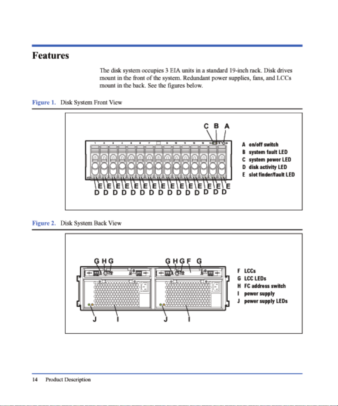
Product Description
General Description
Hewlett-Packard’s StorageWorks Disk System 2405 (referred to in this guide as
the disk system) is a high-availability Fibre Channel (FC) storage product. Dual
optical fiber ports on dual link controllers provide Fibre Channel connections to
the host. Fifteen slots accept high-speed, high-capacity FC disks connected to a
FC midplane. Data throughput is 200 Mbytes/sec. Thirteen disk systems fill a
2-meter System/E rack. Filled with 18-Gbyte disks, the 2-meter Rack System/E
yields 3.51 Terabytes of storage; with 36 -Gbyt e dis ks , 7.0 2 Teraby tes of s t orag e;
and with 73-Gbyte disk, 14.23 Terabytes.
Modular and redundant components are easy to upgrade and maintain. Disks,
power supplies, and link control cards ( LCCs) are replaceable parts that plug into
individual slots in the front and back of the disk system. Redundant power
supply/fan modules and LCCs can be remo ved and replaced without interrupting
storage operations. Disks can be replaced with the system on, and only the
affected file systems taken off -line. Hewlett-Packard technical support is optional
for these procedures.
1
Special electronics and HP-UX software enable remote monitoring and
diagnostics. Sensors on the LCCs monitor the disk system environment,
including temperature, voltage, fan speed, and component status. HewlettPackard’s Command View SDM reports any changes in environmental status to
user-defined locations. Standard HP-UX diagnostic utilities also report
environmental data for enhanced troublesho oti ng.
Product Description 13
Page 14
Page 15

Status Indicators
LEDs on the disk system enable you to detect and replace failed components and
thereby prevent or minimize users’ downtime. For additional information about
LEDs, see chapter 4, Troubleshooting.
On the front of the disk system, a pair of LEDs indicates the status of the disk
system, and an LED for each slot shows disk I/O activity:
■ The system power LED (B in Figure 1) indicates that power is on or off.
■ The system fault LED (C in Figure 1) indi cates whether or not a fault has
■ At the bottom of each disk module, the left LED ( D in Figu re 1) indicates the
■ The right LED, at the bottom of each disk module (E in Figure 1), can be
LEDs (G and J in Figure 2) on the back of the disk system indicate the status of
replaceable components. See chapter 4, Troubleshooting, for specific LED
information.
Power/Standby Switch
Located in the upper right corner of the front of th e disk system, the po wer switch
(A in Figure 1) interrupts power from the power supplies to the LCCs and other
internal components. Power to the power supplies is controlled by the power
cords and the AC source.
Product Description
occurred anywhere in the disk system.
presence of I/O activity on the disk.
flashed to help a customer engineer (CE) locate the disk for physical
inspection or removal.
High Availability
High availability is a general term describing computer systems that are designed
to minimize unplanned downtime. The disk system supports high availability
requirements through the following features:
■ Hot-pluggable, high-capacity, high-speed disks
■ Redundant, hot-pluggable, user-replaceable power supplies and LCCs
■ Support for mirrored disks in the HP-UX environment
■ Online firmware upgrades
■ Hardware event monitoring and real-time error reporting
Product Description 15
Page 16

Upgradability
You can increase disk system storage capacity by:
■ Replacing disk drives with higher-capacity disk drives
■ Adding disks in unused slots
■ Adding another disk system to a FC loop
None of these actions require shutting down the product, but some may require
the use of system utilities to manage file systems.
Disk and LCC firmware is downloadable using the supported tools.
Environmental Services
Environmental services circuitry monitors the following elements:
■ Fan rotation
■ Power supply output
■ Power supply and fan status
■ Disk drive status, including fault conditions
■ LCC status
■ Temperature
■ Self-test results
Each LCC reports the status of all elements in the disk system, even if the LCC
does not have direct access to the element.
16 Product Description
Additionally, the EEPROM on each LCC stores 2 Kbytes of configuration
information and user-defined data, including the manufacturer serial number and
product number.
Page 17

Components
User-replaceable components enable high availability and easy maintenance.
This section describes the following components:
■ Disks and disk fillers
■ LCCs
■ Power supply/fan modules
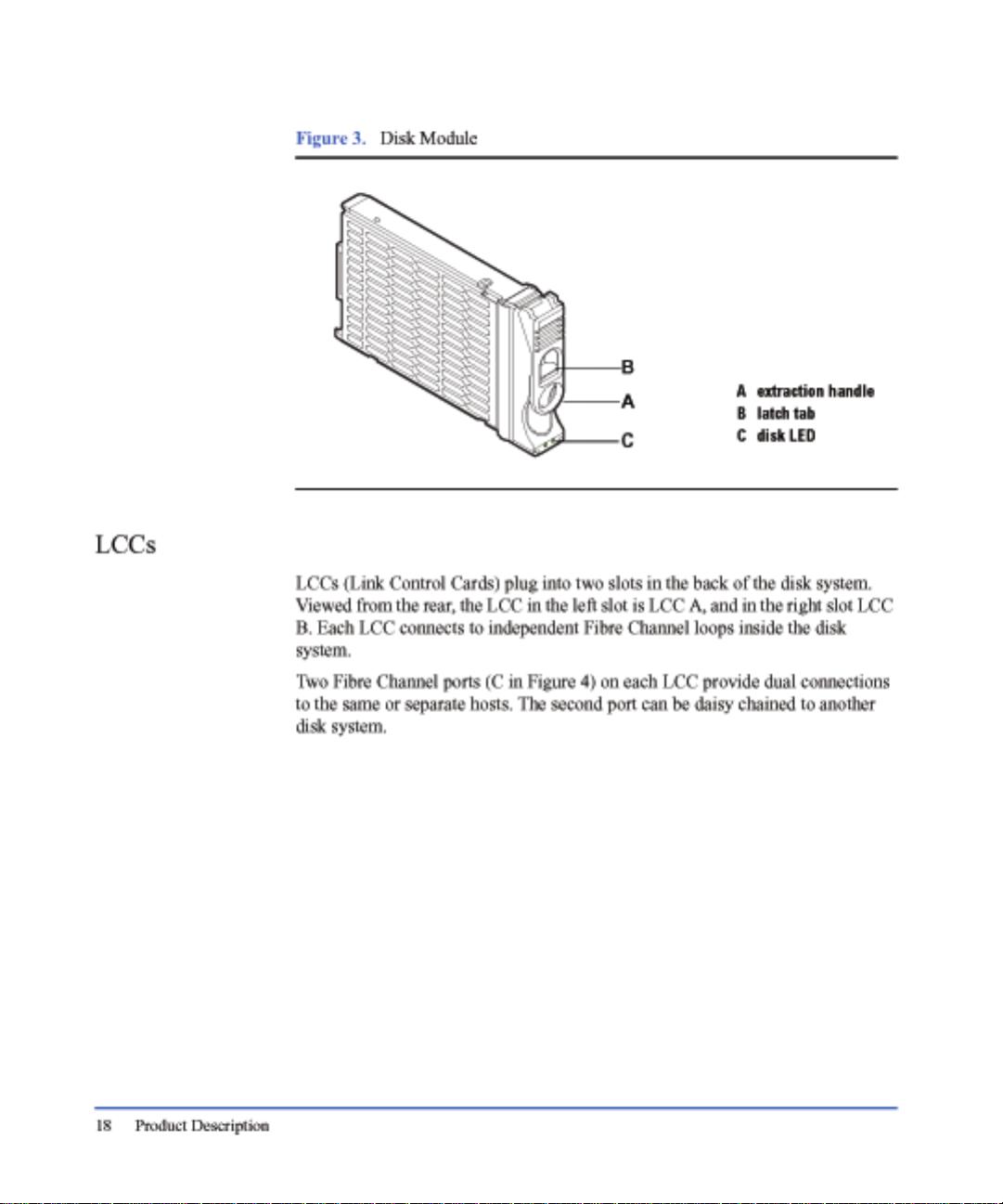
Disks and Disk Fill ers
Disks, shown in Figure 3, are 3.5-inch Low Profile disks in open metal carriers.
Disks are Fibre Channel.
The open carrier design requires careful handling to avoid disk damage by
breakage and static electricity. Avoid personal contact with hot surfaces.
WARNING Touching exposed circuits can cause electrical discharge and
The plastic parts of the disk are safe to touch:
■ Extraction handle (A in Figure 3)
■ Latch tab (B in Figure 3)
The initial disk options for this product are 73-Gbyte, 36-GByte and 18-GByte
drives. A label on the disk carrier s hows the stor age capacity and r otational s peed
of the installed disk. Obtain information about the latest disk option s from HP
sales representatives.
Product Description
disable the disk. Disks require careful handling and ESD
precautions.
Disk fillers occupy unused slots to balance the air flow.
Caution Fillers must be installed in unused slots in order to maintain even
cooling around the remaining slots.
Product Description 17
Page 18
Page 19
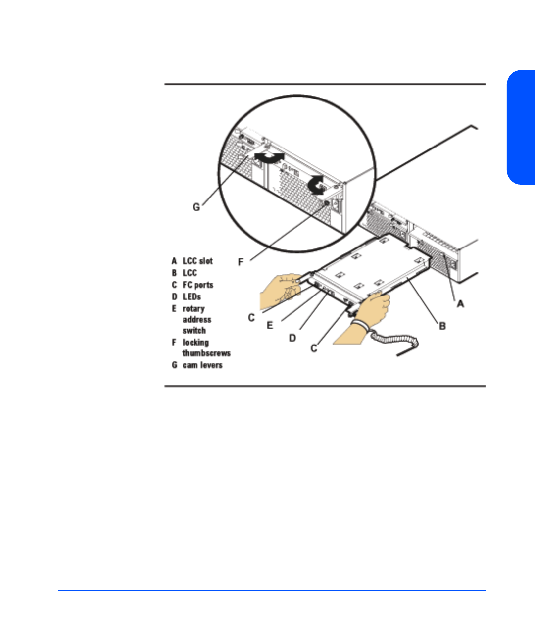
Figure 4. LCC
Product Description
Other features of the LCC are:
■ LEDs (D) indicating LCC status and bus configuration
■ Rotary switch (E)
■ Configuration switch with four settings:
1 Link Speed (1.0625 Gb/s or 2.125 Gb/s)
2 Reserved
3 Reserved
4 Power fail warning (enable/disable)
■ Locking s crews (F)
■ Cam levers (G)
Product Description 19
Page 20

LCC circuitry provides the following functions:
■ System fault detection
■ Disk address generation
Caution If an LCC fails, do not remove it from the disk system until you
are ready to replace it with a new one. The failed LCC should
remain installed to assure proper coo ling for the disk system.
20 Product Description
Page 21
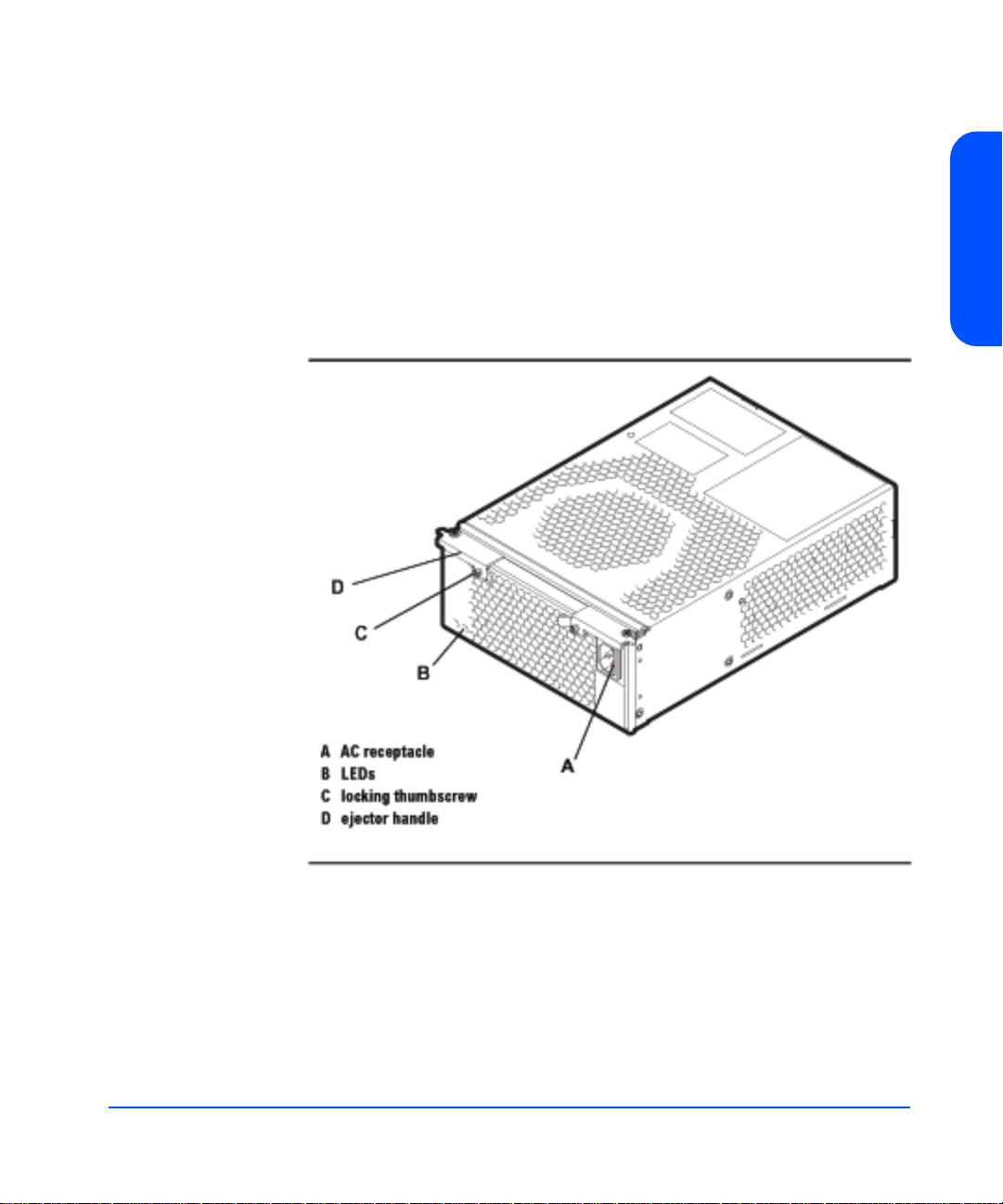
Power Supply/Fan Module
Redundant, hot-pluggable 340-watt power supplies convert wide-ranging AC
voltage from an external main to stable DC output and deliver it to the midplane.
Each power supply has an internal fan, an AC receptacle (A in Figure 5), two
ejector handles (D) with thumbscrews (C), and 2 LEDs (B). Internal control
prevents the rear DC output connector from becoming ener gi zed when the power
supply is removed from the disk system.
Figure 5. Power Su ppl y/F a n Modu le
Product Description
Product Description 21
Page 22

Power supplies share the load reciprocally; that is, each supply automatically
increases its output to compensate for reduced output from the other, and vice
versa. If one power supply fails, the other delivers the entire load.
Internal circuitry triggers a fault when the internal fan or other part fails. At the
same time, the power fault LED (amber) illuminates, and, if enabled, the
hardware event monitor sends an event message. The power supply fan remains
on if other parts fail in order to maintain cooling air flow through the system. If
the fan fails, the power supply shuts down. The fan in the other working power
supply will increase to full speed to compensate for the failed fan. The failed
power supply/fan module must be removed and the replacement power supply/
fan module installed within two minutes. In the event of a failure, if a
replacement fan module/power supply is not available, leave the failed power
supply/fan module installed until you are ready to replace it. This should be done
to maintain proper cooling for the disk system.
Internal circuitry senses fan motion and triggers a fault when the speed of the
power supply’s internal fan falls below a critical level. At the same time, the LED
turns amber, an d, if en abled, the hardware event monitor sends an event message.
22 Product Description
Page 23

Hardware/Software Requirements
The disk system is supported on the following operating systems:
■ HP-UX 11.00 with HWE 0302 or greater
■ HP-UX 11.11 with HWE 0302 or greater
For supported servers, see the latest HP 9000 Configuration and Ordering Guide.
One of the following Fibre Channel HBAs must be installed in the host:
■ A5158A, 1 Gb PCI Fibre Channel HBA
■ A6684A, 1 Gb HSC Fibre Channel HBA
■ A6685A, 1 Gb HSC Fibre Channel HBA
■ A6795A, 2 Gb PCI FIbre Channel HBA
Topologies
The disk system supports high availability through redundan t comp onent s an d
redundant connections to redundant hosts. Each port on a LCC can be connected
to a different host bus adapter in the same or different hosts. Mirroring inside a
disk system is not a high availability solution to the extent that a midplane failure
would necessitate downtime.
Product Description
Basic high availability topologies are described on the following pages. For
information about specific supported topologies, consult an HP sales
representative.
Product Description 23
Page 24
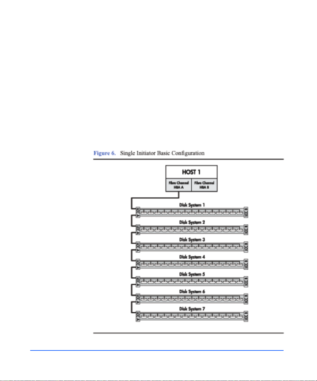
Single Host Basic Configuration
The maximum number of disk systems supported on a Fibre Channel Arbitrated
Loop (FC-AL) is seven. The maximum storage capacity with this configuration
is approximately 7.5 Terabytes (105 disk modules at the 73 Gbyte capacity
point). This configuration does not provide any redundancy to the data path,
however there is some hardware redundancy provided by the enclosures
themselves (power supplies). With the utilization of Mirror/UX software, one or
more mirrors can be created on th e har dware path to p rov ide a basic level of data
protection.
The performance of this co nfigu ration depends on the n umber of d isk sy stems on
the loop. Using the maximum supported number of disk systems reduces the
performance of the loop. To get the maximum performance (200 MB/s or
maximum number of I/Os), the number of disk systems should be limited to four.
24 Product Description
Page 25
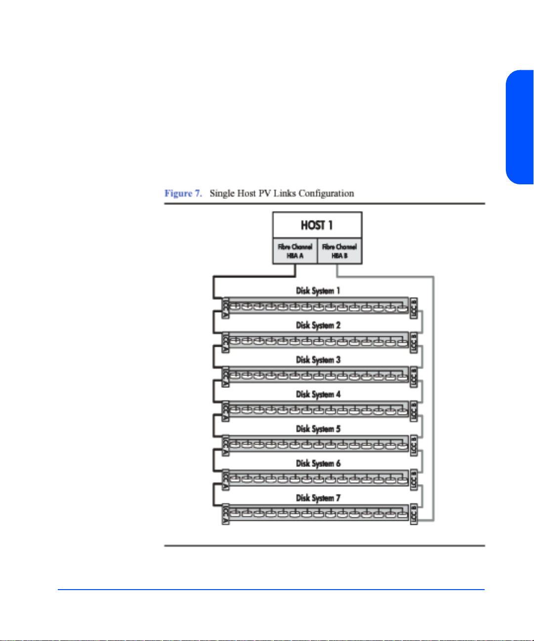
Single Host PV Links Configuration
Data path redundancy can be achieved with the configuration shown in Figure .
Using an additional host bus adapter and the LVM software, pvlinks can be
created to provide a redundant path to data. A separate mirror path can be created
for data protection, also. This configuration protects against any single
component failure (cables, HBAs, disks). Like the single host basic
configuration, each loop is capable of 200 MB/s which translates to 40 0 MB/s for
this configuration.
Product Description
Product Description 25
Page 26

Two Host High Availability Configuration
Figure 8 shows a basic high availability configuration. Each disk system can still
be configured using pvlinks and mirroring. High availability software protects
against a disk system failure. A failure in a cable or LCC will result in a loop
failure. Adding FC-AL loops or switches makes this configuration more robust.
26 Product Description
Page 27

Four Host Hub Configuration
The disk system can run at 2 Gb/s speed. For legacy systems a four host
configuration could be used for an advanced high availability environment at 1
Gb/s speed. See Figure 9, below.
The performance of this configur ation i s limit ed to a ma ximum of 20 0MB/s (10 0
MB/s per loop). The performance issues discussed with the single initiator basic
configuration also apply with this configuration .
Product Description
Product Description 27
Page 28

Definitions
The following terms have specific meanings in the context of this guide:
High availability (HA)
HA describes hardware and software systems that are designed to minimize
planned and unplanned downtime. High availability is measured at the system
level and stated as the percentage of time the system is in a state to do useful
work; for example, 99.95% availability translates to four hours of downtime per
year.
Hot-pluggable
Hot-pluggable signifies the ability of a component to be installed or replaced
without interrupting storage operations and within the restrictions of the
operating environment. All customer -replaceable disk s ystem components can be
replaced under power. Adding or replacing disks o r LCCs may requ ir e the u se of
HP-UX commands to manage file systems.
JBOD
Pronounced jay-bod, a JBOD (Just a Bunch Of Disks) is an enclosed group of
disks that are addressed individually by the host.
PDU and PDRU
PDUs (power distribution units) distribute power from a sing le inlet to multiple
outlets. PRUs (power relay units) connect one or more PDU inlets to a single on/
off switch, such as a cabinet power switch. Units that both distribute and switch
power are referred to as PDRUs.
28 Product Description
Short Wave
Lasers or LEDs that emi t light with wavelen gths around 780 nm or 850 nm . Short
wave lasers are used for Fibre Channel links up to approximately 700 m. They
are typically used with multimode fiber. The preferred fiber core size is 50
microns since this fiber has large bandwidth so the distance is limited by fiber
attenuation. A 62.5 micron core size is also supported for compatibility with
existing FDDI installations. Fiber of this type has smaller bandwidth and, in this
case, the distance is limited by fiber bandwidth.
Page 29

Multimode
A type of fiber optic cable that allows more than one mode (rays of light) to be
guided.
Arbitrated Loop (FC-AL)
A Fibre Channel topology that provides a low-cost solution to attach multiple
communicating ports in a loop without hubs and switches.
Arbitrated Loop Physical Address (AL_PA)
A unique one-byte valid value assigned during Loop Initialization to each
NL_Port or FL_Port on a Loop.
Product Description
Product Description 29
Page 30

30 Product Description
Page 31

Installation
Preparation
Before installing the disk system, make sure (1) electrical wiring, breakers, and
PDUs meet power needs, (2) the required support software is installed on the
host, and (3) if you are connecting the disk system to a V-class server, autotermination is enabled on the host bus adapter. This section covers all three of
these topics.
Electrical Requirements
All electrical wiring to the service point (plug) must be sized to carry the
appropriate inrush (20 amps per power supply) and steady state currents. See the
following table for examples.
Table 1. Inrush (Surge) Current and Duration
No. of Disk Systems on Circuit
(2 power supplies per disk
2
Inrush Current and Duration
system)
1 40 amps declining over 100 ms (5 cycles)
2 80 amps declining over 100 ms (5 cycles)
3 120 amps declining over 100 ms (5 cycles)
4 160 amps declining over 100 ms (5 cycles)
Installation 31
Page 32

Table 2. Maximum Operating Current
Incoming Voltage
AC RMS
Maximum RMS Current Drawn
by One Disk System
100 – 120 volts 4.8 amps
200 – 240 volts 2.0 amps
Caution Adding disk systems to 120V circuits rapidly increases amp
requirements. Always make sure that the total current drawn does
not exceed circuit capacity.
Circuit breakers must be adequately rated for inrush and operating currents.
Hewlett-Packard recommends magnetic-type circuit breakers, which are capable
of handling large inrush currents for short durations (10 to 12 cycles) and are
rated adequately for steady state currents.
Choosing PDUs
Peak power requirements and PDU capacity affect the number of disk systems
that can be installed in a rack. For example, to install more than four disk systems
in Hewlett-Packard legacy racks (HP C27 85A, C2786 A, and C2787A), you must
upgrade to 19-inch PDUs.
Besides rack density, the following factors can help you choose PDUs:
■ Redundant power source. To connect redundant power supplies t o separate
PDUs, install redundant PDUs.
32 Installation
■ Number of cords to the AC source. Using 30-amp PDRUs instead of 16-amp
PDUs reduces the number of cords to the wall.
■ Future needs. Installing surplus PDU capacity allows you to add disk system
units later.
■ Inrush margins. For installations that require four or more 16-amp PDUs,
Hewlett-Packard recommends HP 30-amp PDRUs (E7681A, E7682A) for
their inherent inrush protection.
■ On/Off switch capability. Some PDU/PDRU options support the use of a
single-point on/off switch.
The following tables show how many and what kind of PDU/ PDR U s are needed
to install one or more disk systems in an HP rack. Data assumes 220V AC
Page 33

nominal power and redundant PDU/PDRUs. For nonredundant configurations,
divide the number of recommended PDU/PDRUs by 2.
Table 3. Recommended PDU/PDRUs for Multiple Disk Systems in HP Legacy
Racks
No. of Disk
Systems
1 – 5 2 3-foot/16-amp PDUs
or
2 19-inch/16-amp PDUs
6 – 8 NA
2
1.1 meter
(21 U)
1.6 meter
(32 U)
2 5-foot/16-amp PDUs
2.0 meter
(41 U)
1
or
2 19-inch/16-amp PDUs
4 19-inch/16-amp PDRUs
or
4 19-inch/30-amp PDRUs
9 – 10 NA
2
NA
2
4 19-inch/
30-amp PDRUs
1.Supports cabinet on/off switch.
2.Rack height does not allo w additional disk systems.
Table 4. Recommended PDU/PDRUs for Multiple Disk Systems in HP System/
E Racks
No. of Disk
Systems
1.25 meter
(25 U)
1.6 meter
(33 U)
2.0 meter
(41 U)
1 – 4 2 19-inch/16-amp PDUs
or
2 19-inch/30-amp PDRUs
5 – 8 NA
2
1
2 19-inch/30-amp PDRUs
1
4 19-inch/30-amp PDRUs
9 – 11 NA
2
NA
2
4 19-inch/
30-amp PDRUs
12-13 NA
2
NA
2
4 19-inch/
30-amp PDRUs
Installation
1.Supports cabinet on/off switch.
2.Rack height does not allow additional disk systems.
Installation 33
Page 34

Installing PDU/PDRUs
The 19-inch PDUs and PDRUs can be installed vertically or horizontally in the
rack. Choose PDU/PDRU locations with the following guidelines in mind:
■ Place PDU/PDRUs within the reach of disk system cords.
■ Place PDU/PDRUs vertically whenever possible. See sample installations in
Figure 10 and Figure 11. Installing PDU/PDRUs horizontally interferes with
the ability to service disk systems that are behind the PDU/PDRU.
■ Place vertical PDU/PDRUs on each side of the disk system so that the cord
from either power supply does not cross over replaceable components in the
middle of the product.
■ To achieve maximum density in 2-meter racks, install 30-amp PDRUs on
hinged brackets directly behind disk systems. Hinges allow the PDRU (HP
E7681A and E7682A) to swing aside for servicing obscured components.
(See Figure 11.)
34 Installation
Page 35

Page 36

Page 37

Software Requirements
Ensure that the minimum revisions of HP-UX extension software and online
diagnostics are installed. These release packages enable STM and EMS for the
disk system.
1 At the host console, enter swlist | grep XSW and look for the following
extension software according to the installed HP-UX revision:
— HP-UX 11.00 with HWE 0302 (March 2002 Patch bundles)
— HP-UX 11.11 with HWE 0302 (March 2002 Patch bundles)
2 Enter swlist | grep Online and look for the following online
diagnostics according to the installed HP-UX revision:
— OnlineDiags B.11.00.20.09, or greater, on HP-UX 11.00
— OnlineDiags B.11.11.06.09, or greater, on HP-UX 11.11
If swlist does not report the specified releases, install them from the latest
CD-ROM in any of the following products:
— For HP-UX 11.00:
— For HP-UX 11.11:
Installation
o B3920EA HP-UX OE Media for Servers
o B6261AA HP-UX 11.00 Extension Upgrade Media Kit
o B3920EA HP-UX OE Media for Servers
o B6191AA HP 9000 Support Plus Media
o B6821AA HP-UX TCOE Media
o B6845AA HP-UX 11.11 Minimal Technical OE Media
o B7993AA HP-UX Enterprise OE Server Media
o B7994AA HP-UX Mission Critical OE Comm. Media
The external IT Resource Center web site is:
http://us-support3.external.hp.com/
Installation 37
Page 38

Step 1: Gather Tools
Once the electrical, software, and special V-class preparations are complete,
collect the tools you need to install the disk system hardware:
■ Torx T25 screwdriver
■ Torx T15 screwdriver
■ Small flat-blade screwdriver
Step 2: Unpack the Product
1 Lift off the overcarton and verify the contents of the accessories (top) box.
See Table 5 and Figure 12.
Table 5. Disk System Accessories
Figure
Label
A User guide (A6250-96010)
B Quick installation guide (A6490-96003)
C LCCs (A6255-60001)
D Disk Modules and/or Filler Panels
E Fibre Channel cable(s)
– Rail Kits (not shown)
Part (part number)
38 Installation
Page 39

2 Lift off the accessories box and the top of the under box, and verify the
contents shown in Table 6 and Figure 13.
Table 6. Disk System Contents
Installation
Figure
Label
Part (part number)
A T w o power cords (8120-6514)
B FC Cables (Ordered separately)
C Disk system chassis with previously installed disk modules, link
control cards, and power supply/fan modules
Installation 39
Page 40

40 Installation
3 If a part is missing, contact an HP sales representative.
Page 41

Step 3: Install the device
Follow the procedures in this section to install your storage device in one of the
following rack systems:
■ HP Rack System/E
■ HP Computer Cabinet
■ Rittal-Style Rack
Installing the Storage Device into a Rack System/E
Your storage device can be installed into any of these HP Rack System/E
Products:
■ A4900A HP Rack System/E25 (1.25 M; 25U)
■ A4901A HP Rack System/E33 (1.60 M; 33U)
■ A4902A HP Rack System/E41 (2.00 M; 41U)
1 Check the rail kit contents (see Figure 14). If any parts are missing, call your
nearest HP sales office.
Installation
Installation 41
Page 42

2 Study the installation overview (see Figure 15).
42 Installation
The following tools are required for the installation of the storage device:
■ Flat-blade screwdriver
■ T25 nut driver
WARNING To ensure cabinet or rack stability, and avoid possible injury,
always install the storage devices in the rack or cabinet from the
bottom up.
3 Locate a place on the rack columns with the available space required for the
installation of the storage device. The storag e dev i ce and the rail k it requ ire 3
EIA units of space.
Page 43

Use the following table as a guide for placement of the rails in a Rack System/E
where multiple disk systems will be installed. You can rack multiple disk systems
without gaps by installing rails every three EIA units. For example, s tarting at the
bottom of a 2-meter rack, set rails at the following unit/hole locations:
Table 7. Rail Positions for Sequential Disk Systems
Disk Systems Hole from Rack Bottom
One 1
Two 4
Three 7
Four 10
Five 13
Six 16
Seven 19
Eight 22
Nine 25
Ten 28
Installation
Eleven 31
Installation 43
Page 44

Page 45
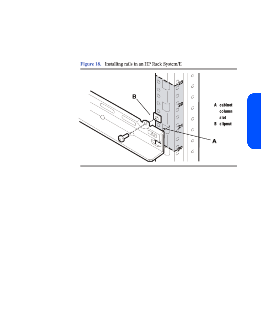
Note Be sure to use the same tab—upper or lower—on opposing rails.
Also, hole patterns vary at opposite ends of the rails.
5 Insert the rail tabs into the appropriate column holes (see A in Figure 18).
Installation
6 Secure the rail ends with one M5 screw each.
7 Install clipnuts on the front columns of the cabinet (see Figure 19). The se are
used for the retention bracket screws.
Installation 45
Page 46

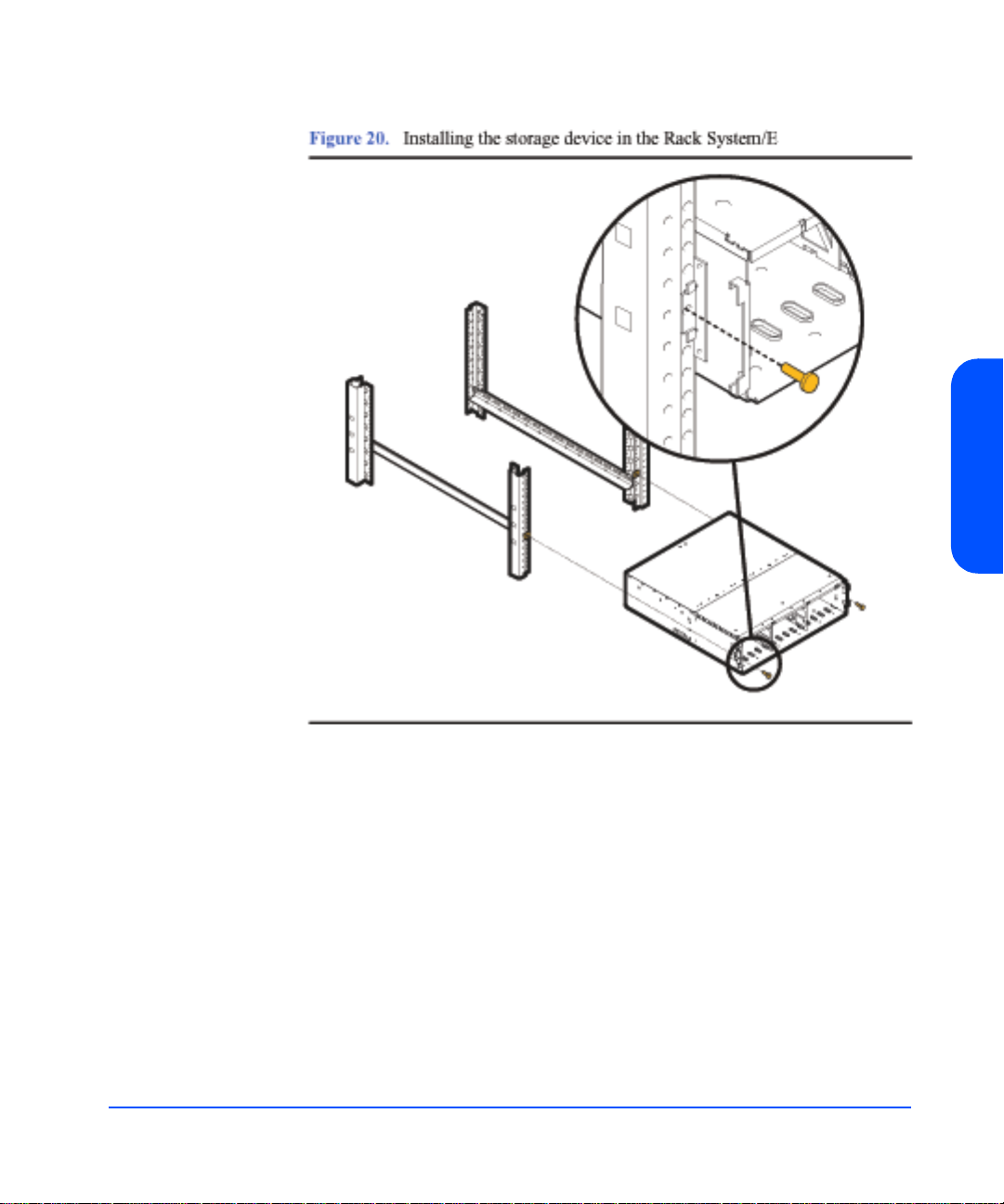
8 Place the storage device on the rails and slide into the cabinet until the
retention bracket comes into contact with the rack column (see Figure 20).
WARNING An empty disk system weighs appro ximately 54 po unds (2 4.5 kg).
T o avoid personal injury, it is recommended that two people install
the storage device in the rack.
9 Insert and tighten the storage device retention (M5) screws through the
retention bracket (see Figure 20).
46 Installation
Page 47
Installation
Installation 47
Page 48

10 Place a rail clamp on each rail and slide them to each bottom rear corner of
the storage device (see Figure 21).
11 Secure the clamps to the rails. Use one 10-32 screw for each rail clamp.
48 Installation
Page 49

Installing the storage device into an HP Computer Cabinet
Your storage device can be installed into the following Computer Cabinets:
■ C2785A Computer Cabinet (1.10M; 21U)
■ C2786A Computer Cabinet (1.60M; 32U)
■ C2787A Computer Cabinet (1.96M; 41U)
Caution To ensure proper installation, only use the instructions in this
manual for installing the storage device in the HP Computer
Cabinet. Do not use the instructions enclosed in the rail kit box.
1 Check the rail kit contents (see Figure 22). If any parts are missing, call your
nearest HP sales office. The tie-down clamp is not used and may be
discarded.
Installation
Installation 49
Page 50
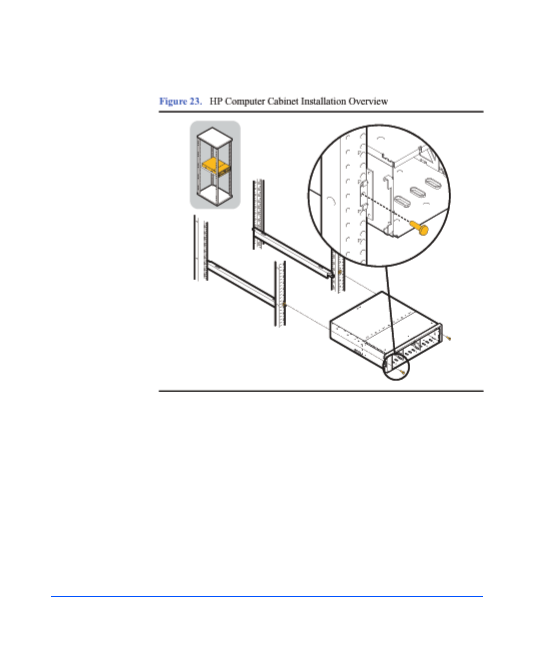
2 Study the installation overview (see Figure 23).
50 Installation
The following tools are required for the installation of the storage device:
■ Flat-blade screwdriver
■ T25 nut driver
WARNING To ensure cabinet or rack stability and avoid possible injury,
always install the storage devices in the rack or cabinet from the
bottom up.
3 Locate a place on the rack columns with the available space required for the
installation of the storage device. The storag e dev i ce and the rail k it requ ire 4
EIA units of space, three units for the storage device and one unit for the rails
(see Figure 24).
Page 51

Page 52

5 Insert the rail tabs into the appropriate holes on the HP Computer Cabin et
columns (see A in Figure 26).
6 Secure the rail ends with one M5 screw each.
52 Installation
Page 53

7 Install clipnuts on the front columns of the cabinet (see Figure 27). The se are
used for the device retention screws.
8 Place the storage device on the rails and slide it into the cabinet until the
retention bracket comes in contact with the rack column (see Figure 28).
Installation
WARNING An empty disk system weighs appro ximately 54 po unds (2 4.5 kg).
T o avoid personal injury, it is recommended that two people install
the storage device in the rack.
Installation 53
Page 54

9 Tighten the storage device retention (M5) screws through the retention
bracket (see Figure 28).
54 Installation
Page 55

10 Install a filler panel in the space below the storage device.
Installation
Installation 55
Page 56

Installing the Storage Device into a Rittal-Style Rack
Your storage device can be installed into the Rittal-Style Rack by doing the
following steps:
1 Inspect the contents of the rail kit. If any parts are missing, call your nearest
HP sales office (see Figure 30).
56 Installation
2 Align the front of rails to the inside of the front cabinet column.
Carefully observe the alignment of the groups of holes on the columns so the
holes in the rails align properly (see Figure 31).
Page 57

Page 58

4 Extend the adjustable slide to the back column of the cabinet.
5 Insert the mounting screws and finger tighten them through the rear column
of the cabinet (see Figure 33).
58 Installation
Page 59

6 Tighten the center nuts to finger tightness (see Figure 34).
7 Tighten all screws to their final tightness using a driver.
Tighten the screws that hold the rail to the columns first, before tightening the
center slide nuts to their final tightness.
Installation
8 Repeat the procedure above for the other rail.
Installation 59
Page 60
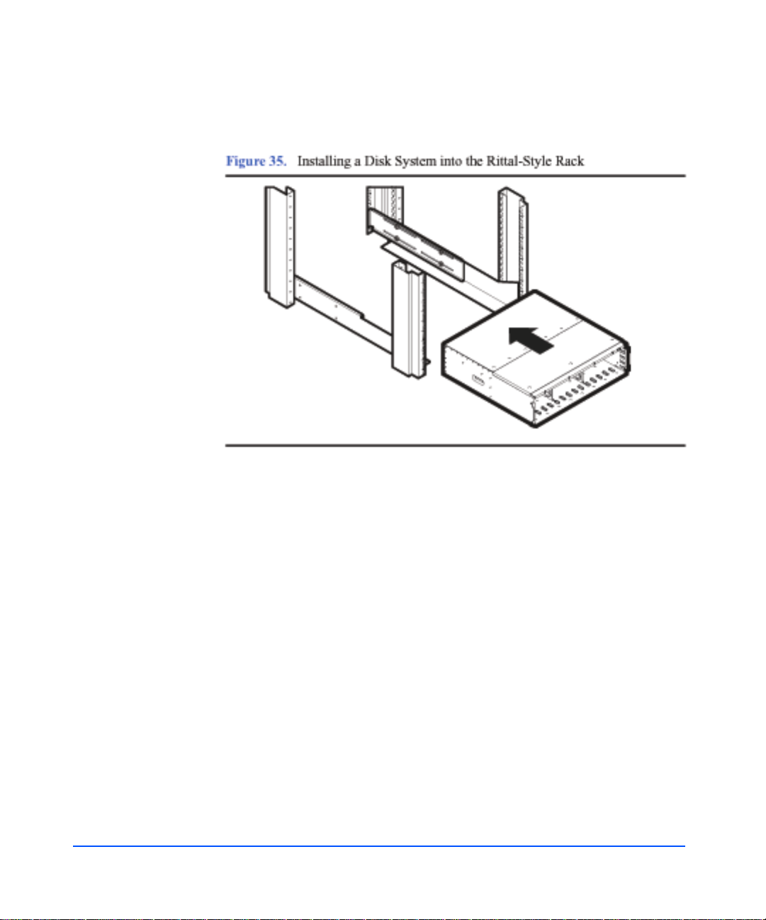
9 Insert the disk system (with disk modules and power supplies removed) onto
the rails (see Figure 35).
60 Installation
Page 61
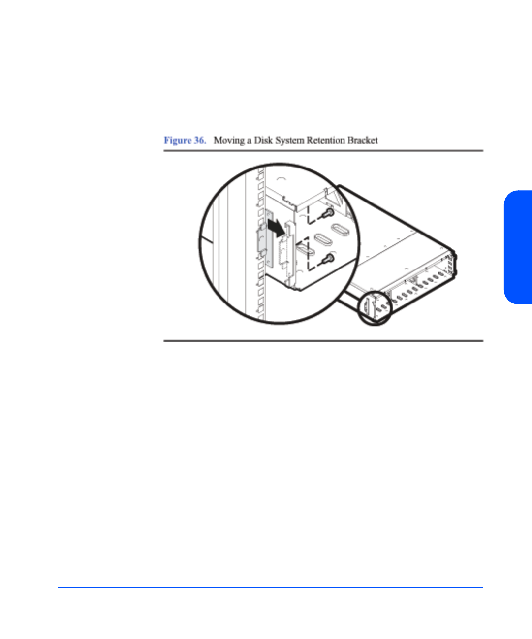
10 Move the disk system retention brackets to the fron tm ost set o f mo untin g
holes.
This allows the disk system to install further back into the cabinet; and allows
the cabinet doors (if present) to close properly (see Figure 36).
Installation
Installation 61
Page 62

11 Push the disk system back into the rack until the disk system retaining bracket
is flush against the front column of the rack.
12 Bolt the disk system to the front column. Use the fifth hole from the top of the
front of the rail (see Figure 37).
62 Installation
Page 63

Install the Disk System
1 Remove the power supply/fan modules to prepare the disk system for lifting:
a Loosen the screws in the extractor handles of each power supply/fan
module with the chassis still in the box.
b Pull the extractor handles out from the center of the power supply to
disengage it from the midplane. Pull each power supply/fan modu le out of
the chassis. Support the far end of the power supply /fan modul e with your
free hand as it clears the chassis.
c Set the power supply/fan modules aside, on an antistatic pad, to be
reinstalled later.
WARNING An empty disk system weighs appro ximately 54 po unds (2 4.5 kg).
T o avoid personal injury, it is recommended that two people install
the storage device in the rack.
2 Remove the disk modules from the disk system. Place them aside on the pink
antistatic foam pad supplied with your disk syst em.
3 Carry the disk system to the front of the rack and slide the back end onto the
rails (Figure 35) with the help of another person or using a lifting device.
Push the disk system into the rack as far as it will go.
Installation
Installation 63
Page 64

Step 4: Configure LCCs
The disk system comes with two LCCs installed.
If you are connecting this disk system to an HP St orageWorks Virtual Array 7400
or to a 1 Gb/s hub, the link speed switch must be set to 1 Gb/s.
1 Attach your ESD strap to ground.
2 Remove the LCC from the disk system chassis.
Caution Do not touch the pins on the back of the LCC.
3 Set internal configuration dip switch to appropriate link speed.
Be sure to set the internal LCC data t ransmission speed swit ch to 1
Gb/s or 2 Gb/s as appropriate for your configuration. See Figure 2.29
for more detailed information.
64 Installation
Page 65
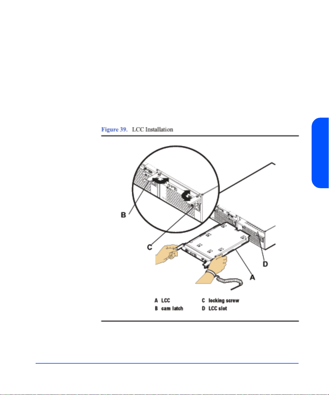
4 Open the LCC cam latches (B in Figure 39) by pulling them away from the
center.
5 Align the LCC with the slot (D in Figure 39), and insert the LCC into the slot
at the back of the disk system. Stop pushing when the LCC meets the
midplane.
6 Press the cam latches inward and flat against the center. The cam action
draws the LCC completely into the slot and seats the connector pins on the
midplane.
7 Tighten the locking thumbscrews (C).
Installation
8 Repeat steps 2 through 7, installing the second LCC in the remaining empty
slot.
Installation 65
Page 66
Page 67
Page 68

Page 69

Page 70

Page 71

Page 72

Step 6: Connect FC and Power Cables
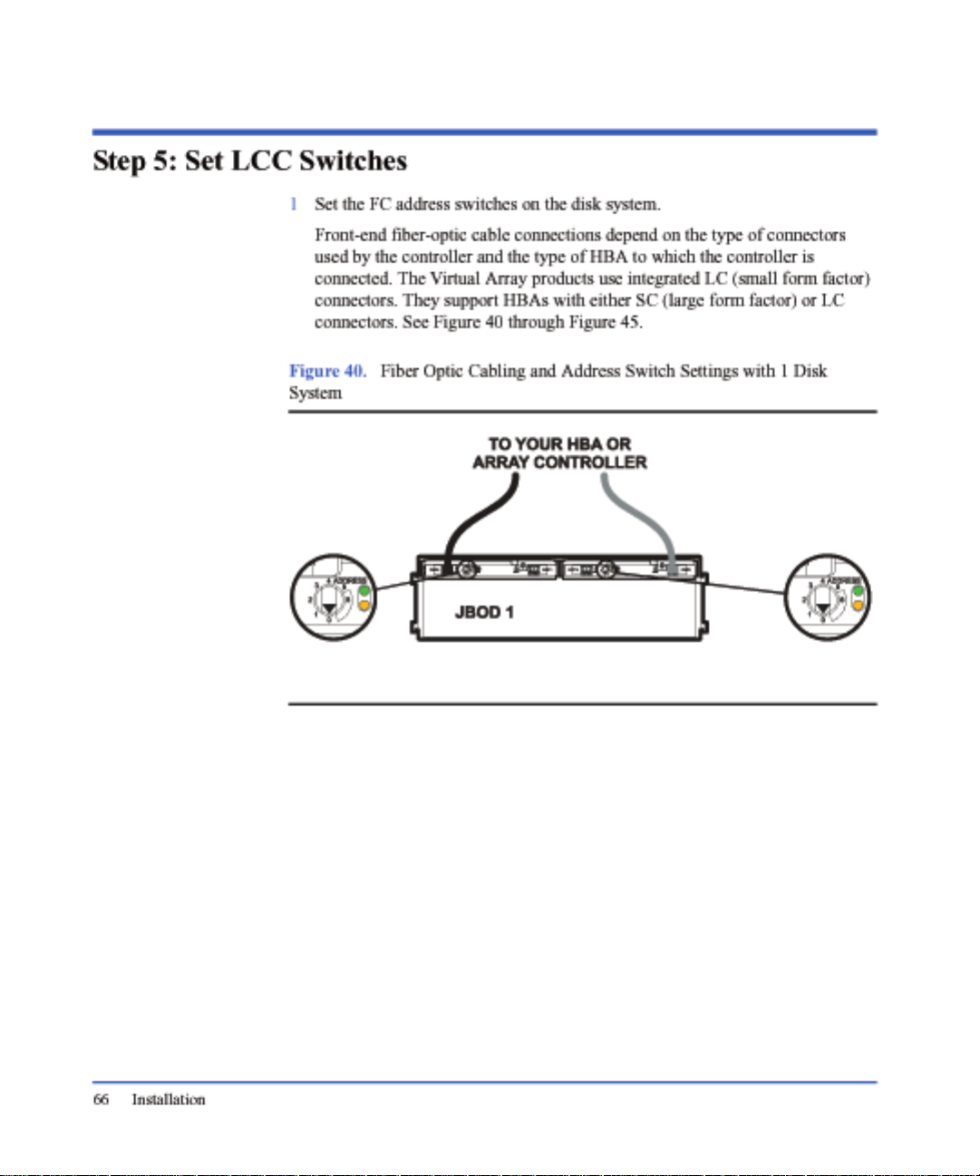
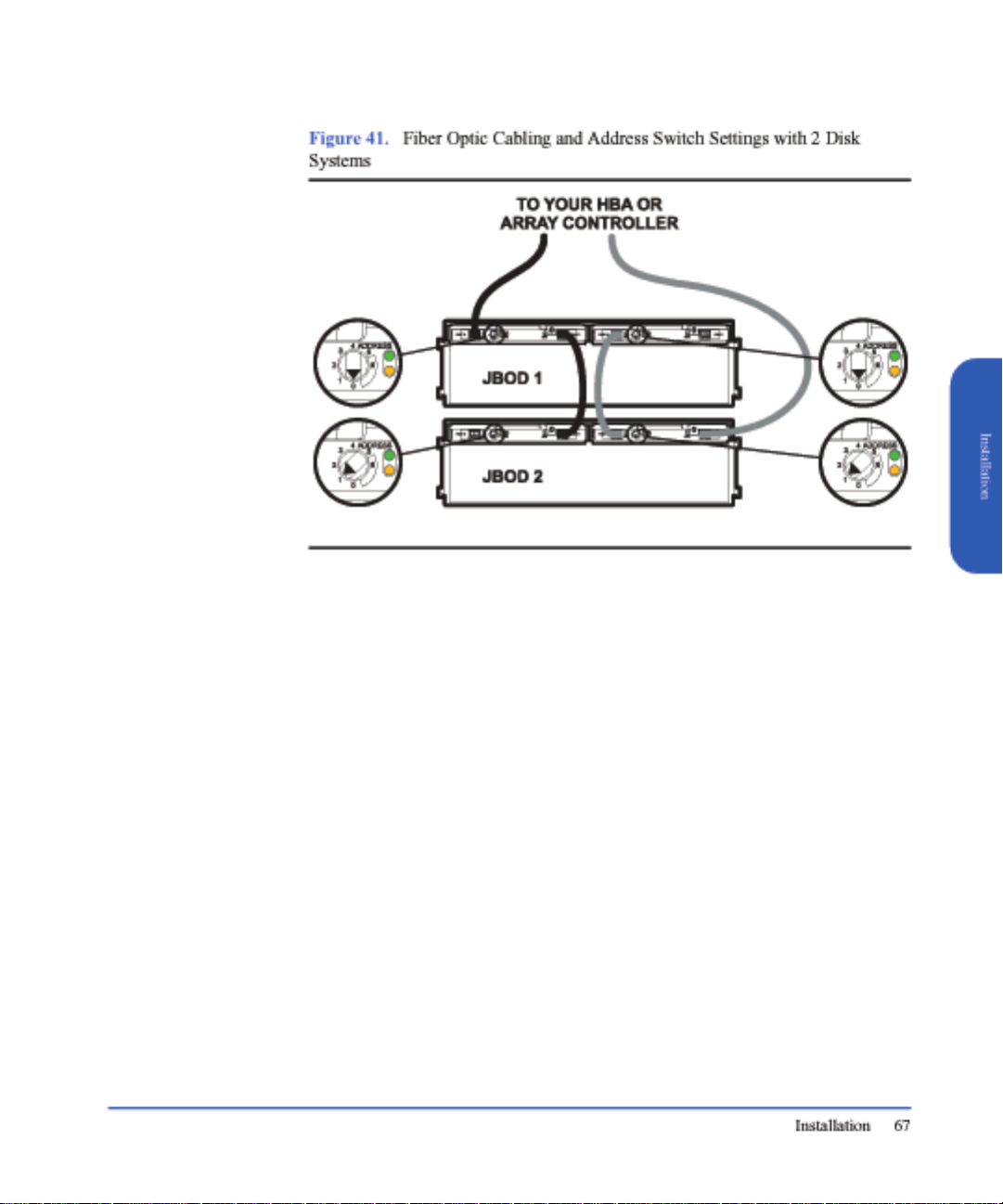
1 Connect the front-end fiber-optic cables.
Front-end fiber-optic cable connections depend on the type of connectors
used by the controller and the type of HBA to which the controller is
connected. The Virtual Array Products use integrated LC (small form factor)
connectors. They support HBAs with either SC (large form factor) or LC
connectors. See Figure 40 through Figure 45.
2 Connect power cords to the power receptacle on the power supply/fan
module(s).
3 Attach the other end of each power cord to a preinstalled PDU/PDRU.
Choose outlets according to the following guidelines:
— Redundancy . To extend the redundancy of the product, attach each cord to
a different PDU. This is represented in Figure 46 and Figure 47.
— Reliability. To avoid cascading faults for a group of disk systems that are
plugged int o the same PDU, distribute redundant power cords to as many
different combinat ions of PDUs as possi ble. See Figu re 46 and Figure 47.
Cascading faults occur when a backup PDU is overloaded with power
surges after the primary PDU fails.
— Serviceability. Choose PDU locations that prevent power cords from
interfering with the removal and replacement of serviceable components.
Also leave a 6-inch service loop to allow for the rotation of PDRUs.
72 Installation
The letters in Fig ures 46 and 47 represent ind e pend ent P DU s or P DU ban ks . Th e
absence of duplicate letters in individual disk systems indicates the products are
using redundant PDUs. The minimal number of duplicate letter pairs indicates
the disk systems are protected against cascading faults.
Page 73

Page 74

Page 75

Step 7: Install Disk Modules
Caution Touching exposed areas on the disk can cause electrical discharge
and disable the disk. Be sure you are grounded and be careful not
to touch exposed circuits.
Disk modules are fragile and ESD sensitive. Dropping one end of the disk just
two inches is enough to cause permanent damage. In addition, static electricity
can destroy the magnetic properties of recording surfaces. Grip disks only by
their handles (A in Figure48) and carriers (C), and follow strict ESD procedures.
Installation
Installation 75
Page 76

1 Determine which slots, 1 through 15, will contain disk modules and which
will contain fillers.
At least two slots must con tain disk modules.
2 Put on the ESD strap and attach the other end of the strap appropriately.
Caution Disk modules are fragile. Handle carefully. Be careful to grasp the
disk module by its handle and avoid touching exposed circuitry.
3 Remove a disk module from the disk pack and its ESD bag.
4 Open the disk module cam latch (C) by pulling the tab toward you.
5 Push the disk module as far as it will go into the selected slot.
6 Close the cam latch by pushing the latch toward the disk until it clicks. The
cam action draws the disk module completely into the slot and seats the
connecting pins on the midplane.
7 Repeat steps 4 through 6 to install add itional disk modules.
8 Install disk fillers in the remaining slots.
Caution Every slot must contain either a disk module or filler.
Step 8: Turn on the Disk System
Caution When starting up the disk system, do not override autom a tic spin-
up of the drives. Doing so could cause an overcurrent fault,
requiring a power cycle to recover.
Press in the power/standby switch with the retracted tip of a pen or pencil to
power-on the disk system (see Figure 49). Allow 2 minutes for the disk drives
and controllers to complete their self-tests.
76 Installation
1 Press the power/stan dby switch (C in Figure 49) to turn on the disk system.
2 Watch the system LEDs for confirmation that the disk system is operational.
The system power LED (A ) sh ould be green, and the faul t LED (B) s hould b e
off.
If the LEDs indicate a problem, refer to chapter 4, Troubleshooting.
Note An amber light that is on briefly when a component turns on is
normal. If this light remains on more than a couple seconds, a fault
has been detected.
Page 77

Page 78

Step 9: Verify Devices on the Host
On the host system ru n IOSCAN (ioscan -f) and veri f y t ha t the d i sks an d LCC (s)
are listed in IOSCAN output. If the displayed “S/W State” is not “claimed,”
begin troubleshooting (see chapte r 4).
Sample IOSCAN
Each LCC (ctl) or disk appears as a separate target in IOSCAN output.
Class I H/W Path Driver S/W State H/W Type Description
==============================================================================================
fc 0 0/4/0/0 fcT1 CLAIMED INTERFACE HP Fibre Channel Mass Storage
Adapter
lan 1 0/4/0/0.5 fcT1_cntl CLAIMED INTERFACE HP Fibre Channel Mass Storage
Cntl
fcp 0 0/4/0/0.8 fcp CLAIMED INTERFACE FCP Protocol Adapter
ba 4 0/5 lba CLAIMED BUS_NEXUS Local PCI Bus Adapter (782)
lan 2 0/5/0/0 btlan5 CLAIMED INTERFACE PCI Ethernet (10110019)
ba 5 0/8 lba CLAIMED BUS_NEXUS Local PCI Bus Adapter (782)
fc 4 0/8/0/0 td CLAIMED INTERFACE HP Tachyon TL/TS Fibre Channel
Mass Storage Adapter
fcp 4 0/8/0/0.8 fcp CLAIMED INTERFACE FCP Protocol Adapter
ext_bus 10 0/8/0/0.8.0.255.0 fcpdev CLAIMED INTERFACE FCP Device Interface
target 5 0/8/0/0.8.0.255.0.0 tgt CLAIMED DEVICE
disk 140 0/8/0/0.8.0.255.0.0.0 sdisk CLAIMED DEVICE HP 18.2GST318451FC
target 6 0/8/0/0.8.0.255.0.1 tgt CLAIMED DEVICE
disk 141 0/8/0/0.8.0.255.0.1.0 sdisk CLAIMED DEVICE HP 18.2GST318451FC
target 7 0/8/0/0.8.0.255.0.2 tgt CLAIMED DEVICE
disk 64 0/8/0/0.8.0.255.0.2.0 sdisk CLAIMED DEVICE HP 18.2GST318451FC
target 8 0/8/0/0.8.0.255.0.3 tgt CLAIMED DEVICE
disk 65 0/8/0/0.8.0.255.0.3.0 sdisk CLAIMED DEVICE HP 18.2GST318451FC
target 9 0/8/0/0.8.0.255.0.4 tgt CLAIMED DEVICE
disk 142 0/8/0/0.8.0.255.0.4.0 sdisk CLAIMED DEVICE HP 36.4GST336704FC
target 10 0/8/0/0.8.0.255.0.5 tgt CLAIMED DEVICE
disk 143 0/8/0/0.8.0.255.0.5.0 sdisk CLAIMED DEVICE HP 36.4GST336704FC
target 11 0/8/0/0.8.0.255.0.6 tgt CLAIMED DEVICE
disk 144 0/8/0/0.8.0.255.0.6.0 sdisk CLAIMED DEVICE HP 36.4GST336704FC
target 12 0/8/0/0.8.0.255.0.7 tgt CLAIMED DEVICE
78 Installation
Page 79

disk 145 0/8/0/0.8.0.255.0.7.0 sdisk CLAIMED DEVICE HP 36.4GST336704FC
target 13 0/8/0/0.8.0.255.0.8 tgt CLAIMED DEVICE
disk 146 0/8/0/0.8.0.255.0.8.0 sdisk CLAIMED DEVICE HP 36.4GST336704FC
The “descriptions” in this example represent some of the valid disk modules.
Valid disk descriptions include:
■ ST336704FC36-Gbyte 10K rpm FC disk module
ST336605FC
■ ST373405FC73-Gbyte 10K rpm FC disk module
■ ST318451FC18-Gbyte 15K rpm FC disk module
ST318452FC
■ ST336752FC36-Gbyte 15K rpm FC disk module
Where do you go from here?
For operating system and application configuration information, refer to the
documentation for your particular server’s operating system.
Installation
Installation 79
Page 80

80 Installation
Page 81

Configuration
3
Viewing a Disk System in IOSCAN
An IOSCAN (example below) shows each LCC (0/8/0/0.8) and disk in the
system.
Sample IOSCAN
Type the command: ioscan -fn
Class I H/W Path Driver S/W State H/W Type Description
===========================================================================================
fcp 4 0/8/0/0.8 fcp CLAIMED INTERFACE FCP Protocol Adapter
ext_bus 10 0/8/0/0.8.0.255.0 fcpdev CLAIMED INTERFACE FCP Device Interface
target 5 0/8/0/0.8.0.255.0.0 tgt CLAIMED DEVICE
disk 140 0/8/0/0.8.0.255.0.0.0 sdisk CLAIMED DEVICE HP 18.2GST318451FC
/dev/dsk/c10t0d0 /dev/rdsk/c10t0d0
target 6 0/8/0/0.8.0.255.0.1 tgt CLAIMED DEVICE
disk 141 0/8/0/0.8.0.255.0.1.0 sdisk CLAIMED DEVICE HP 18.2GST318451FC
/dev/dsk/c10t1d0 /dev/rdsk/c10t1d0
target 7 0/8/0/0.8.0.255.0.2 tgt CLAIMED DEVICE
disk 64 0/8/0/0.8.0.255.0.2.0 sdisk CLAIMED DEVICE HP 18.2GST318451FC
/dev/dsk/c10t2d0 /dev/rdsk/c10t2d0
target 8 0/8/0/0.8.0.255.0.3 tgt CLAIMED DEVICE
disk 65 0/8/0/0.8.0.255.0.3.0 sdisk CLAIMED DEVICE HP 18.2GST318451FC
/dev/dsk/c10t3d0 /dev/rdsk/c10t3d0
target 9 0/8/0/0.8.0.255.0.4 tgt CLAIMED DEVICE
disk 142 0/8/0/0.8.0.255.0.4.0 sdisk CLAIMED DEVICE HP 36.4GST336704FC
/dev/dsk/c10t4d0 /dev/rdsk/c10t4d0
target 10 0/8/0/0.8.0.255.0.5 tgt CLAIMED DEVICE
disk 143 0/8/0/0.8.0.255.0.5.0 sdisk CLAIMED DEVICE HP 36.4GST336704FC
Configuration 81
Page 82

/dev/dsk/c10t5d0 /dev/rdsk/c10t5d0
target 11 0/8/0/0.8.0.255.0.6 tgt CLAIMED DEVICE
disk 144 0/8/0/0.8.0.255.0.6.0 sdisk CLAIMED DEVICE HP 36.4GST336704FC
/dev/dsk/c10t6d0 /dev/rdsk/c10t6d0
target 12 0/8/0/0.8.0.255.0.7 tgt CLAIMED DEVICE
disk 145 0/8/0/0.8.0.255.0.7.0 sdisk CLAIMED DEVICE HP 36.4GST336704FC
/dev/dsk/c10t7d0 /dev/rdsk/c10t7d0
target 13 0/8/0/0.8.0.255.0.8 tgt CLAIMED DEVICE
disk 146 0/8/0/0.8.0.255.0.8.0 sdisk CLAIMED DEVICE HP 36.4GST336704FC
/dev/dsk/c10t8d0 /dev/rdsk/c10t8d0
target 14 0/8/0/0.8.0.255.0.9 tgt CLAIMED DEVICE
disk 147 0/8/0/0.8.0.255.0.9.0 sdisk CLAIMED DEVICE HP 36.4GST336704FC
/dev/dsk/c10t9d0 /dev/rdsk/c10t9d0
target 15 0/8/0/0.8.0.255.0.10 tgt CLAIMED DEVICE
disk 148 0/8/0/0.8.0.255.0.10.0 sdisk CLAIMED DEVICE HP 36.4GST336704FC
/dev/dsk/c10t10d0 /dev/rdsk/c10t10d0
target 16 0/8/0/0.8.0.255.0.11 tgt CLAIMED DEVICE
disk 149 0/8/0/0.8.0.255.0.11.0 sdisk CLAIMED DEVICE HP 36.4GST336704FC
/dev/dsk/c10t11d0 /dev/rdsk/c10t11d0
target 17 0/8/0/0.8.0.255.0.12 tgt CLAIMED DEVICE
disk 150 0/8/0/0.8.0.255.0.12.0 sdisk CLAIMED DEVICE HP 36.4GST336704FC
/dev/dsk/c10t12d0 /dev/rdsk/c10t12d0
target 18 0/8/0/0.8.0.255.0.13 tgt CLAIMED DEVICE
disk 151 0/8/0/0.8.0.255.0.13.0 sdisk CLAIMED DEVICE HP 36.4GST336704FC
/dev/dsk/c10t13d0 /dev/rdsk/c10t13d0
target 19 0/8/0/0.8.0.255.0.14 tgt CLAIMED DEVICE
disk 185 0/8/0/0.8.0.255.0.14.0 sdisk CLAIMED DEVICE HP 36.4GST336704FC
/dev/dsk/c10t14d0 /dev/rdsk/c10t14d0
target 20 0/8/0/0.8.0.255.0.15 tgt CLAIMED DEVICE
ctl 7 0/8/0/0.8.0.255.0.15.0 sctl CLAIMED DEVICE HP A6255A
/dev/rscsi/c10t15d0
82 Configuration
Page 83

The disks shown in the previous sample ioscan -fn are the ST318451FC (used in
the A6191A disk module) and the ST336704FC (used in the A6192A disk
module). The full descriptions of the supported disk modules are:
■ ST336605FC 36 Gbyte 10K rpm disk FC disk module (A6192A)
ST336704FC
■ ST373405FC 73 Gbyte 10K rpm disk FC disk module (A6194A)
■ ST318451FC 18 Gbyte 15K rpm disk FC disk module (A6191A)
ST318452FC
■ ST336752FC 36 Gbyte 15K rpm disk FC disk module (A6193A)
Interpreting the Hardware Path
The elements of the Fibre Channel hardware path are interpreted as follows:
8/12.8.0.255.2.14.0
Port (255 = the target connected directly to the FC)
Area (0 = point-to-point or private loop)
Protocol Type (8 = mass storage)
Adapter
Bus Converter
The loop ID, broken out in upper and lower bits in the example above, is 46. To
derive the loop ID from the Bus and Target values of the hardware path:
1 Convert the Bus and Target fields (the upper and lower bits of th e loop ID) to
binary:
Configuration
LUN (Logical Unit Number of disk)
Target (Lower 4 bits of the loop ID)
Bus (Upper 4 bits of the loop ID)
8/12.8.0.255.2.14.0
1 1 1 0 (Lower 4 bits of the loop ID)
0 0 1 0 (Upper 4 bits of the loop ID)
Configuration 83
Page 84

2 Combine the two binary fields into 8 bits and convert back to decimal:
Upper bit Lower bit
0 0 1 0 1 1 1 0
32 + 8+4+2 = 46
Loop IDs and Hardware Paths by Enclosure ID
The rotary switch on the LCC set the Fibre-Channel Address range for the
enclosure. Both LCCs should be set identically for proper redundancy. Multiple
enclosures need to have unique settings to avoid address conflicts. If devices are
physically present and are not reported as found, suspect address conflicts with
other devices. The following tables helps understand what addressing is being
used:
Table 8. Loop IDs and Hardware Paths by Slot Number and Enclosure ID 0 - 2
Encl.
ID
Disk
Slot #
(dec)
Loop
ID
(dec)
0 1 2
Bus
(dec)
Tgt
(dec)
ALPA
(hex)
Loop
ID
(dec)
Bus
(dec)
Tgt
(dec)
ALPA
(hex)
Loop
(dec)
ID
Bus
(dec)
Tgt
(dec)
ALPA
(hex)
1 000EF1610CD3220B2
2 101 E81711CC3321B1
3 200 E41812CB3422AE
4 303 E21913CA3523AD
5 404 E12014C93624AC
6 505 E02115C73725AB
7 606DC2216 C63826AA
8 707DA2317C53927A9
9 808D92418 C34028A7
10 9 0 9 D6251 9 BC412 9 A6
84 Configuration
Page 85

Table 8. Loop IDs and Hardware Paths by Slot Number and Enclosure ID 0 - 2
Encl.
ID
Disk
Slot #
(dec)
Loop
ID
(dec)
0 1 2
Bus
(dec)
Tgt
(dec)
ALPA
(hex)
Loop
ID
(dec)
Bus
(dec)
Tgt
(dec)
ALPA
(hex)
Loop
(dec)
ID
Bus
(dec)
Tgt
(dec)
ALPA
(hex)
1110010D526110BA42210A5
12 11 0 11 D4 27 1 11 B9 43 2 11 A3
1312012D328112B644 129F
1413013d2 29113B5452139E
1514014D130114B446214B4
SES15015CE31115B363315 73
Table 9. Loop IDs and Hardware Paths by Slot Number and Enclosure ID 3 - 4
Encl.
ID
Disk
Slot #
(dec)
Loop
ID
(dec)
Bus
(dec)
3 4
Tgt
(dec)
ALPA
(hex)
Loop
ID
(dec)
Bus
(dec)
Tgt
(dec)
ALPA
(hex)
Configuration
1 483 0 98 644 0 72
2 493 1 97 654 1 71
3 503 2 90 664 2 6E
4 513 3 8F 674 3 6D
5 523 4 88 684 4 6C
6 533 5 84 694 5 6B
7 543 6 82 704 6 6A
8 553 7 81 714 7 69
Configuration 85
Page 86

Table 9. Loop IDs and Hardware Paths by Slot Number and Enclosure ID 3 - 4
Encl.
ID
Disk
Slot #
(dec)
Loop
ID
(dec)
Bus
(dec)
3 4
Tgt
(dec)
ALPA
(hex)
Loop
ID
(dec)
Bus
(dec)
Tgt
(dec)
ALPA
(hex)
9 563 8 80 804 8 67
10 57 3 9 7C 73 4 9 66
1158310 7A 74410 65
12 59 3 11 79 75 4 11 63
1360312 76 76412 5C
1461313 75 77413 5A
1562314 74 78414 59
SES79415 56 79415 56
Table 10. Loop IDs and Hardware Paths by Slot Number and Enclosure ID 5- 6
Encl.
ID
5 6
Disk
Slot #
(dec)
Loop
ID
(dec)
Bus
(dec)
Tgt
(dec)
ALPA
(hex)
Loop
ID
(dec)
Bus
(dec)
Tgt
(dec)
1 80 5 0 55 96 6 0 3A
2 81 5 1 54 97 6 1 39
3 82 5 2 53 98 6 2 36
4 835 3 52 996 3 35
5 84 5 4 51 100 6 4 34
6 85 5 5 4E 101 6 5 33
86 Configuration
ALPA
(hex)
Page 87

Table 10. Loop IDs and Hardware Paths by Slot Number and Enclosure ID 5- 6
Encl.
ID
Disk
Slot #
(dec)
Loop
ID
(dec)
Bus
(dec)
5 6
Tgt
(dec)
ALPA
(hex)
Loop
ID
(dec)
Bus
(dec)
Tgt
(dec)
ALPA
(hex)
7 86 5 6 4D 102 6 6 32
8 87 5 7 4C 103 6 7 31
9 88 5 8 4B 104 6 8 2E
10 89 5 9 4A 105 6 9 2D
1190510 49 106610 2C
12 91 5 11 47 107 6 11 2B
13 92 5 12 46 108 6 12 2A
14 93 5 13 45 109 6 13 29
15 94 5 14 43 110 6 14 27
SES95515 3C 111615 26
Configuration
In the above tables, columns 0-6 correspond to possible switch settings. Rows 115 indicate the disk slot positions. SES refers the address reserved for the
enclosure controller . The inters ection of a row and a column con tains the loop ID
the device will take. The loop ID is translated to a Fibre Channel address (ALPA) by firmware according to the table in the FC-AL2 standard.
Enclosure IDs (0 through 6) are set with a dial on the LCC. This setting
determines the FC-AL IDs of the disks and LCCs in the disk system. See Table 8
and Table 10 for the FC-AL IDs and corresponding hardware paths for each slot
and LCC bas ed on the Enclosure ID.
Caution The Enclosure IDs on both LCCs in t he sa me dis k sy st em mu st be
identical.
For redundancy , each LCC is connected to a differ ent Fibre Channel loop (that is,
a different host bus adapter).
Configuration 87
Page 88

Setting Up the Hardware Event Monitor
Separate monitors watch over the disks and the disk system. You need to install
and configure the Disk Monitor (disk_em) and the High Availability Storage
System Monitor (dm_ses_enclosure) for complete event notification.
To install and configure the required monitors, refer to the EMS Hardware
Monitors User’s Guide, which is included in Adobe Acrobat format on the IPR
Support Media. You can download a copy of Acrobat Reader without charge
from http://www.adobe.com/prodindex/acrobat/readstep.html.
Aliasing Devices (HP-Qualified Only)
Using host-based software, you can “label” each disk system with any
information that would be useful for the site . You might use this feature to assign
an inventory number or to indicate the location of the product. The maximum
length of the annotation is 256 characters.
Using SAM
To define a text string using SAM, select the desired LCC or disk from the Disk
Devices list; then select Annotate Device from the Actions menu. Type the
comment that you want in the Annotation field and select OK.
You can view the annotation through the Annotate Device option in the Actions
menu or by displaying the Annotation column in the Disk Devices list. To
include the Annotation column in the Disk Devices window, select Columns
from the View menu and choose Annotation.
Using STM (HP-Qualified Only)
Annotating devices is a password-protected function of STM (Support Tools
Manager). Use the System menu License option to install the HP-Only license
before you select the annotate function.
1 Run STM and install the HP-Only license.
2 Select the desired LCC.
3 Select Expert Tool > Run from the Tools menu. An Expert Tool window
opens.
88 Configuration
Page 89

4 Select Write Label from the Info menu. The User Defined Annotation
window, similar to the screen shown below, displays the existing label in an
edit field.
Figure 50. Annotate Device Using STM
5 Type the desired text in the New User Defined Annotation field. Click OK.
The new label will replace the existing label.
To view the annotation of a selected disk system, select Read Label from the
Expert Tool Info menu. The label is displayed in the Expert Tool window.
Configuration
Configuration 89
Page 90

Updating Firmware (HP-Qualified Only)
Obtain the latest disk system firmware release from the support web site before
traveling to the customer site. When you arrive at the site:
1 Save the firmware file on the customer’s system, preferably in the default
firmware directory: /var/tmp
2 If you wan t to run STM in gra phic mode, make sure DISPLAY is exported.
3 Start STM by typing xstm& on the HP-UX command line. This command
starts the graphic version of STM and keeps the X window open when you
quit STM.
4 Select License from the System menu and install the password-protected
HP-Only license.
5 Select Firmware Update > Run from the Tools menu. A tool window opens,
displaying the current firmware version and instructions for upd ating. A
second window lists the available firmware files in the var/tmp directory.
That second window is similar to the one shown below.
Figure 51. Firmware File Selection Window
90 Configuration
If there are no firmware files in the default directory, a pop-up window instructs
you to select an optional path and STM displays a list of directories. Enter the
directory path you used to save the firmware file (in step 1) and click OK.
Page 91

6 Select the firmware file from the list of files displayed in the default or
specified directory. Click OK.
7 Select Start Update... f rom the Updat e menu. STM p rompt s yo u to co nfirm or
cancel the firmware update. A window is similar to the one shown below.
Figure 52. Firmware Download Confirmation Window
Configuration
Configuration 91
Page 92
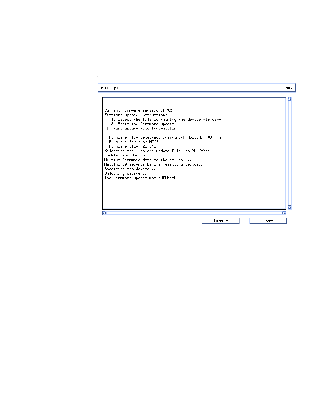
The results of your action appear in the Tool window. The screen that appears is
similar to the illustration shown below.
Figure 53. Firmware Tool Window
92 Configuration
Page 93

Troubleshooting
Overview
The following steps will help you identify and resolve disk sy stem failures:
8 Gather information from all sources:
— Event notifications (page 93)
— Disk system LED stat us (page 96)
— Online information tools (page 98)
9 Isolate the cause of the problem (page 104).
10 Correct the problem (chapter 5, Removal and Replacement).
11 Verify operational status with IOSCAN or other host utilities.
Event Notification
4
The EMS hardware event monitor polls environmental services on the LCC and
reports any changes in the status of monitored components. Depending on how
the monitor is set up, you can receive messages at the console, in e-mail, in a log
file, or through third-party applications. These messages are likely to be the first
indication of a problem with a disk system.
Events are reported for changes in temperature, voltage, and the status of
replaceable components.
Troubleshooting 93
Page 94

Messages identify five levels of severity:
Critical An event that causes data loss, host system downtime,
or other loss of service. Host system operation will be
affected if the disk system continues to be used w ithou t
correction. Immediate action is required.
Serious An event that may cause data loss, host system
downtime, or other loss of service if left uncorrected.
Host system and hardware operation may be adversely
affected. The problem needs repair as soon as possible.
Major Warning An event that could escalate to a serious condition if
not corrected. Host system operation should not be
affected and normal use of the disk system can
continue. Repair is needed but at a convenient time.
Minor Warning An event that will n ot likely escalate to a severe
condition if left uncorrected. Host system operation
will not be interrupted and normal use of the disk
system can continue. The problem can be repaired
when convenient.
Information An event that is expected as part of the normal
operation of the hardware. No action is required.
Event messages (see Figure 54) contain the following:
94 Troubleshooting
■ Message Data – Date and time the message was sent, the source and
destination of the message, and the severity level
■ Event Data – Date and time of the event, the host, event ID, name of the
monitor, event number, event class, severity level, hardware path, associated
OS error log entry ID
■ Error Description – Narrative information indicating the component that
experienced the event and the nature of the event
■ Probable Cause/Recommended Action – The cause of the event and
suggested steps toward a solution. This information should be the first step in
troubleshooting.
■ Annotation – The user-defined annotation associated with the specific disk
system
Page 95

Figure 54. Sample Hardware Event Notification
Notification Time: Wed Feb 3 11:27:15 1999
yourserver sent Event Monitor notification information:
/storage/events/enclosures/ses_enclosure/8_0_1_0.15.0 is >=1.
Its current value is MAJORWARNING(3)
Event data from monitor:
Event Time: Wed Feb 3 11:27:15 1999
Hostname: yourserver.rose.hp.com IP Address : 15.43.213.13
Event ID: 0x0036b8a313000000002 Monitor : dm_ses_enclosure
Event # : 402 Event Class: I/O
Severity : MAJOR WARNING
Enclosure at hardware path 8/0/1/0.15.0: Hardware failure
Associated OS error log entry id(s): None
Description of Error:
The enclosure services controllers have different versions of
firmware.
Probable Cause / Recommended Action:
The enclosure services controller cards have different versions of
firmware. Update the controllers to the same version of firmware.
User Defined Annotation: Enclosure 37 LCC A.
Troubleshooting 95
Troubleshooting
Page 96

Status LEDs
LEDs indicate the status of the disk system itself and each of its comp onents (see
Table 11). Green and amber system LEDs are visible on the front of the disk
system. They show that power is on (green) and a fault has occurred (amber).
Disk activity (green) LEDs are on the front of the disk drives at the bottom. Other
LEDs are on individual components in the back of the disk system.
Table 11. LED Functions
LED State Indication
System Powe r Green Power is on.
96 Troubleshooting
LED states are described in Table 11:
OFF Power is off.
Page 97

Table 11. LED Functions
LED State Indication
System Fault Ambe r Self-test1 / Problem.
2
OFF Normal operation.
Flashing LCC A & B DIP switch settings do not match.
1
LCC Fault Amber Self-test
/ Fault.
OFF Normal operation.
Flashing Peer LCC DIP switch settings do not match.
Link Active Green Port is in use.
OFF Port is disabl ed (bypassed).
2G ON Disk system is configured for 2.125 Gb/ s operation.
OFF Disk system is configured for 1.0625 Gb/s operation.
1
Power Supply Amber Start-up
/ Fault.
Green Operating.
OFF Power is off.
Disk Activity
3
ON Installed and spinning up. If the LED is still on 3 minutes
after power is engaged, the disk may be faulty.
Flashing There is input/output activity to the disk.
OFF Not installed or not operating.
1.Start-up and self-tests occur briefly when the unit is powered on.
2.A component has fa iled ; te mper atur e or vol tage i s out of n orm al rang e. S ee Iso lat ing Caus es
on page 104.
3.When a disk is installed with power on, its activity LED stays on until the disk has spun up.
When the disk is ready, the LED turns off. Thereafter, it flashes when there is I/O to the disk.
Note An amber light that is on briefly when a component first comes on
is normal. If this light remains on more than a couple of seconds, a
fault has been detected.
Troubleshooting 97
Troubleshooting
Page 98

Online Status Information
Software applications that run on HP-UX hosts display status and descriptive
information about the disk system and its components. SAM is the system
administrator’s interface to specific HP-UX functions. STM is the service
engineer’s tool for information, diagnostics, firmware updates, and more.
Viewing Component Status in SAM
SAM displays the status of disk system components on the host console. Follow
the instructions below to use SAM:
1 Select Disks and File Systems from the main window.
2 Select Disk Devices . SAM displays the hardware paths of all disks, disk
systems, and arrays on the host.
3 Select the path that represents the LCC of the desired disk system. You can
recognize the LCC by the description “HP Disk System 2405 Controller.”
4 Select View More Info from the Actions menu. A window displays header
information and a graphical representation of the front of the disk system.
The header provides the following information:
— LCC Hardware path - the path chosen from the Disk Devices list
— Peer LCC Hardware path - the path to the other LCC in the same unit
— Controller’s ID Switch Setting - Enclosure ID, set by the dial on the LCC
bulkhead
98 Troubleshooting
— Enclosure’s logical ID - the enclosure’s World Wide Name, a unique
identifier in the Fibre Channel network
5 For a view of the back of the selected disk system, click the “Back” tab.
6 To view component information, click the button representing the
component. SAM displays the following information about specific
components:
Button Displays
Disk Disk Slot, hardware path, status
LCC Hardware path, status, firmware revision
Power Supply Name, status
Page 99

Status values are OK, critical error, noncritical, not installed, unknown, and
status not available. See Interpreting Status Values on page 100 for the meanings
of these terms.
Viewing the STM Information Log
STM generates Information and Activity logs for a selected disk system. Execu te
STM in an X window and run the Information tool as follows.
1 At the system prompt, ty pe xstm&.
2 Select the desired disk system (HP A6250A).
3 Select Information from the Tools menu.
4 To generate a current log, select Run.
5 To view log output, select Information from the Tools menu.
6 Select Information Log.
7 Select Done when you have finished viewing the information.
The contents of the STM Information Log are as follows:
Log creation time The date and time the I nfo rmatio n Tool was last
Hardware path The physical path from the host to the reporting
run for the selected disk system.
LCC; for example, 8/12.8.0.255.2.14.0.
Product ID A6250A, the HP product number of the disk
system.
FC Loop ID The FC-AL ID of the reporting LCC, a decimal
value between 0 and 125.
LCC A Status The reported status of LCC A in the selected disk
system. Possible values are OK, critical,
noncritical, not installed, or not available.
LCC B Status The reported status of LCC B in the selected disk
system. Possible values are OK, critical,
noncritical, not installed, or not available.
Reporting LCC LCC A or LCC B, whichever LCC corresponds to
the selected hardware path.
Troubleshooting 99
Troubleshooting
Page 100

Enclosure ID The unique manufacturer number that
distinguishes the reporting LCC from all other
LCCs.
WW Name (node) The World Wide Name assigned to this disk
system. In normal operation, this value is the same
as the Wo rld Wide Name (port) for LCC A.
WW Name (port) The World Wide Name of the reporting LCC.
Firmware Rev. The current firmware version on the reporting
LCC.
Power Supply Status The status of the left (Supply A) and right (Supply
B) power supplies in the selected disk system.
Possible values are OK, critical, not installed, or
not available.
Voltage Sensors
Voltage and Status
Temp Sensors
Temperature and Status
Interpreting Status Values
SAM and STM report status in common terms, which are defined as follows:
Table 12. Status Indications
Reported
Status
OK All replaceable
Applicable
Component
components and
sensors
The voltage detected and status of three voltage
sensors—3.3V, 5.0V, and 12V—on each LCC.
Possible status values are OK, critical, noncritical,
not installed, unknown, and not availabl e.
The temperature detected and status of four
sensors. Possible status values are OK, critical,
noncritical, not installed, unknown, or not
available.
Indication
Component is installed and no error
conditions are known.
100 Troubleshooting
 Loading...