

HP StorageWorks 2000sa G2, StorageWorks 2312sa G2, StorageWorks 2324sa G2 User Manual

HP StorageWorks
2000sa G2 Modular Smart Array
User Guide
Part number: 488320-003
First edition: May 2009

Legal and notice information
© Copyright 2009 Hewlett-Packard Development Company, L.P.
The information combined herein is subject to change without notice. The only warranties for HP products and services are set forth in the express
warranty statements accompanying such products and services. Nothing herein should be construed as constituting an additional warranty. HP shall
not be liable for technical or editorial errors or omissions contained herein.
Microsoft, Windows, Windows NT, and Windows XP are U.S. registered trademarks of Microsoft Corporation.
UNIX® is a registered trademark of The Open Group.
WARRANTY STATEMENT: To obtain a copy of the warranty for this product, see the warranty information website:
http://www.hp.com/go/storagewarranty.

Contents
About this guide. . . . . . . . . . . . . . . . . . . . . . . . . . . . . . . . . . . . . . . . . . . . . . . . . . . . . . 11
Intended audience . . . . . . . . . . . . . . . . . . . . . . . . . . . . . . . . . . . . . . . . . . . . . . . . . . . . . . . . . . . . . . 11
Prerequisites. . . . . . . . . . . . . . . . . . . . . . . . . . . . . . . . . . . . . . . . . . . . . . . . . . . . . . . . . . . . . . . . . . . 11
Related documentation . . . . . . . . . . . . . . . . . . . . . . . . . . . . . . . . . . . . . . . . . . . . . . . . . . . . . . . . . . . 11
Document conventions and symbols . . . . . . . . . . . . . . . . . . . . . . . . . . . . . . . . . . . . . . . . . . . . . . . . . . 12
Rack stability . . . . . . . . . . . . . . . . . . . . . . . . . . . . . . . . . . . . . . . . . . . . . . . . . . . . . . . . . . . . . . . . . . 13
HP technical support . . . . . . . . . . . . . . . . . . . . . . . . . . . . . . . . . . . . . . . . . . . . . . . . . . . . . . . . . . . . . 13
Customer self repair . . . . . . . . . . . . . . . . . . . . . . . . . . . . . . . . . . . . . . . . . . . . . . . . . . . . . . . . . . . . . 13
Product warranties . . . . . . . . . . . . . . . . . . . . . . . . . . . . . . . . . . . . . . . . . . . . . . . . . . . . . . . . . . . . . . 13
Subscription service . . . . . . . . . . . . . . . . . . . . . . . . . . . . . . . . . . . . . . . . . . . . . . . . . . . . . . . . . . . . . 13
HP web sites . . . . . . . . . . . . . . . . . . . . . . . . . . . . . . . . . . . . . . . . . . . . . . . . . . . . . . . . . . . . . . . . . . 13
Documentation feedback . . . . . . . . . . . . . . . . . . . . . . . . . . . . . . . . . . . . . . . . . . . . . . . . . . . . . . . . . . 14
1 Overview . . . . . . . . . . . . . . . . . . . . . . . . . . . . . . . . . . . . . . . . . . . . . . . . . . . . . . . . 15
Features and benefits . . . . . . . . . . . . . . . . . . . . . . . . . . . . . . . . . . . . . . . . . . . . . . . . . . . . . . . . . . . . 15
2 Components . . . . . . . . . . . . . . . . . . . . . . . . . . . . . . . . . . . . . . . . . . . . . . . . . . . . . . 17
Front panel components . . . . . . . . . . . . . . . . . . . . . . . . . . . . . . . . . . . . . . . . . . . . . . . . . . . . . . . . . . 17
2312sa G2 . . . . . . . . . . . . . . . . . . . . . . . . . . . . . . . . . . . . . . . . . . . . . . . . . . . . . . . . . . . . . . . . 17
2324sa G2 . . . . . . . . . . . . . . . . . . . . . . . . . . . . . . . . . . . . . . . . . . . . . . . . . . . . . . . . . . . . . . . . 17
Disk drive bay numbers . . . . . . . . . . . . . . . . . . . . . . . . . . . . . . . . . . . . . . . . . . . . . . . . . . . . . . . . . . . 18
Rear panel components . . . . . . . . . . . . . . . . . . . . . . . . . . . . . . . . . . . . . . . . . . . . . . . . . . . . . . . . . . 18
2312sa G2 and 2324sa G2 . . . . . . . . . . . . . . . . . . . . . . . . . . . . . . . . . . . . . . . . . . . . . . . . . . . . 18
MSA2000 3.5" 12-drive enclosure. . . . . . . . . . . . . . . . . . . . . . . . . . . . . . . . . . . . . . . . . . . . . . . . . . . 19
MSA70 2.5” 25-drive enclosure. . . . . . . . . . . . . . . . . . . . . . . . . . . . . . . . . . . . . . . . . . . . . . . . . . . . . 19
Cache . . . . . . . . . . . . . . . . . . . . . . . . . . . . . . . . . . . . . . . . . . . . . . . . . . . . . . . . . . . . . . . . . . . . . . . 19
Transportable CompactFlash . . . . . . . . . . . . . . . . . . . . . . . . . . . . . . . . . . . . . . . . . . . . . . . . . . . . . . . 19
Super-capacitor pack . . . . . . . . . . . . . . . . . . . . . . . . . . . . . . . . . . . . . . . . . . . . . . . . . . . . . . . . . . . . 20
3 Installing the enclosures. . . . . . . . . . . . . . . . . . . . . . . . . . . . . . . . . . . . . . . . . . . . . . . 21
Installation checklist . . . . . . . . . . . . . . . . . . . . . . . . . . . . . . . . . . . . . . . . . . . . . . . . . . . . . . . . . . . . . 21
Connecting controller and drive enclosures . . . . . . . . . . . . . . . . . . . . . . . . . . . . . . . . . . . . . . . . . . . . . 22
Connecting controller and MSA2000 3.5" 12-drive enclosures . . . . . . . . . . . . . . . . . . . . . . . . . . . . . 22
Connecting controller and MSA70 2.5” 25-drive enclosures . . . . . . . . . . . . . . . . . . . . . . . . . . . . . . . 22
Connecting controller and mixed-connect 3.5” and 2.5” drive enclosures. . . . . . . . . . . . . . . . . . . . . . 22
Additional cable requirements for drive enclosures. . . . . . . . . . . . . . . . . . . . . . . . . . . . . . . . . . . . . . 22
2312sa G2 and 2324sa G2 cable requirements . . . . . . . . . . . . . . . . . . . . . . . . . . . . . . . . . . . . . . 22
Testing enclosure connections. . . . . . . . . . . . . . . . . . . . . . . . . . . . . . . . . . . . . . . . . . . . . . . . . . . . . . . 26
Obtaining IP values. . . . . . . . . . . . . . . . . . . . . . . . . . . . . . . . . . . . . . . . . . . . . . . . . . . . . . . . . . . . . . 27
Setting management port IP addresses using DHCP . . . . . . . . . . . . . . . . . . . . . . . . . . . . . . . . . . . . . 27
Setting management port IP addresses using the CLI. . . . . . . . . . . . . . . . . . . . . . . . . . . . . . . . . . . . . 27
4 Connecting hosts . . . . . . . . . . . . . . . . . . . . . . . . . . . . . . . . . . . . . . . . . . . . . . . . . . . 31
Host system requirements. . . . . . . . . . . . . . . . . . . . . . . . . . . . . . . . . . . . . . . . . . . . . . . . . . . . . . . . . . 31
Connecting the enclosure to data hosts . . . . . . . . . . . . . . . . . . . . . . . . . . . . . . . . . . . . . . . . . . . . . . . . 31
SAS host ports. . . . . . . . . . . . . . . . . . . . . . . . . . . . . . . . . . . . . . . . . . . . . . . . . . . . . . . . . . . . . . . 31
Connecting direct attach configurations . . . . . . . . . . . . . . . . . . . . . . . . . . . . . . . . . . . . . . . . . . . . . 32
Single controller configuration . . . . . . . . . . . . . . . . . . . . . . . . . . . . . . . . . . . . . . . . . . . . . . . . . 32
One server/one HBA/single path . . . . . . . . . . . . . . . . . . . . . . . . . . . . . . . . . . . . . . . . . . . . 32
Dual controller configurations . . . . . . . . . . . . . . . . . . . . . . . . . . . . . . . . . . . . . . . . . . . . . . . . . . 32
One server/one HBA/dual path . . . . . . . . . . . . . . . . . . . . . . . . . . . . . . . . . . . . . . . . . . . . . 32
Two servers/one HBA per server/dual path . . . . . . . . . . . . . . . . . . . . . . . . . . . . . . . . . . . . . 32
Four servers/one HBA per server/dual path . . . . . . . . . . . . . . . . . . . . . . . . . . . . . . . . . . . . . 32
Connecting switch attach configurations . . . . . . . . . . . . . . . . . . . . . . . . . . . . . . . . . . . . . . . . . . . . . 33
HP StorageWorks 2000sa G2 Modular Smart Array User Guide 3

Blade enclosure configuration . . . . . . . . . . . . . . . . . . . . . . . . . . . . . . . . . . . . . . . . . . . . . . . . . 34
Blade servers/two 3Gb SAS BL switches. . . . . . . . . . . . . . . . . . . . . . . . . . . . . . . . . . . . . . . . 34
Connecting remote management hosts . . . . . . . . . . . . . . . . . . . . . . . . . . . . . . . . . . . . . . . . . . . . . . . . 34
5 Basic operation. . . . . . . . . . . . . . . . . . . . . . . . . . . . . . . . . . . . . . . . . . . . . . . . . . . . 35
Powering on/powering off . . . . . . . . . . . . . . . . . . . . . . . . . . . . . . . . . . . . . . . . . . . . . . . . . . . . . . . . 35
Updating firmware . . . . . . . . . . . . . . . . . . . . . . . . . . . . . . . . . . . . . . . . . . . . . . . . . . . . . . . . . . . . . . 35
Selecting an appropriate time to perform the online upgrade . . . . . . . . . . . . . . . . . . . . . . . . . . . . . . 35
6 LED descriptions . . . . . . . . . . . . . . . . . . . . . . . . . . . . . . . . . . . . . . . . . . . . . . . . . . . 37
Front panel LEDs. . . . . . . . . . . . . . . . . . . . . . . . . . . . . . . . . . . . . . . . . . . . . . . . . . . . . . . . . . . . . . . . 37
Disk drive LEDs. . . . . . . . . . . . . . . . . . . . . . . . . . . . . . . . . . . . . . . . . . . . . . . . . . . . . . . . . . . . . . . . . 38
Rear panel LEDs . . . . . . . . . . . . . . . . . . . . . . . . . . . . . . . . . . . . . . . . . . . . . . . . . . . . . . . . . . . . . . . . 40
2312sa G2 and 2324sa G2 . . . . . . . . . . . . . . . . . . . . . . . . . . . . . . . . . . . . . . . . . . . . . . . . . . . . 40
MSA2000 3.5" 12-drive enclosure . . . . . . . . . . . . . . . . . . . . . . . . . . . . . . . . . . . . . . . . . . . . . . . . 42
MSA70 2.5” 25-drive enclosure . . . . . . . . . . . . . . . . . . . . . . . . . . . . . . . . . . . . . . . . . . . . . . . . . . 42
Power supply LEDs. . . . . . . . . . . . . . . . . . . . . . . . . . . . . . . . . . . . . . . . . . . . . . . . . . . . . . . . . . . . 43
7 Configuring a system for the first time . . . . . . . . . . . . . . . . . . . . . . . . . . . . . . . . . . . . 45
Configuring your web browser for SMU . . . . . . . . . . . . . . . . . . . . . . . . . . . . . . . . . . . . . . . . . . . . . . . 45
Signing in to SMU . . . . . . . . . . . . . . . . . . . . . . . . . . . . . . . . . . . . . . . . . . . . . . . . . . . . . . . . . . . . . . 45
Tips for using the main window . . . . . . . . . . . . . . . . . . . . . . . . . . . . . . . . . . . . . . . . . . . . . . . . . . . 45
Tips for using the help window . . . . . . . . . . . . . . . . . . . . . . . . . . . . . . . . . . . . . . . . . . . . . . . . . . . 46
Changing the system date and time . . . . . . . . . . . . . . . . . . . . . . . . . . . . . . . . . . . . . . . . . . . . . . . . . . 46
To use manual date and time settings . . . . . . . . . . . . . . . . . . . . . . . . . . . . . . . . . . . . . . . . . . . . 46
To obtain the date and time from an NTP server . . . . . . . . . . . . . . . . . . . . . . . . . . . . . . . . . . . . . 47
Using the Configuration Wizard. . . . . . . . . . . . . . . . . . . . . . . . . . . . . . . . . . . . . . . . . . . . . . . . . . . . . 48
Using the Provisioning Wizard. . . . . . . . . . . . . . . . . . . . . . . . . . . . . . . . . . . . . . . . . . . . . . . . . . . . . . 49
Testing the configuration . . . . . . . . . . . . . . . . . . . . . . . . . . . . . . . . . . . . . . . . . . . . . . . . . . . . . . . . . . 49
Signing out of SMU . . . . . . . . . . . . . . . . . . . . . . . . . . . . . . . . . . . . . . . . . . . . . . . . . . . . . . . . . . . . . 49
8 Troubleshooting . . . . . . . . . . . . . . . . . . . . . . . . . . . . . . . . . . . . . . . . . . . . . . . . . . . 51
Fault isolation methodology . . . . . . . . . . . . . . . . . . . . . . . . . . . . . . . . . . . . . . . . . . . . . . . . . . . . . . . . 51
Gather fault information . . . . . . . . . . . . . . . . . . . . . . . . . . . . . . . . . . . . . . . . . . . . . . . . . . . . . . . . 51
Determine where the fault is occurring . . . . . . . . . . . . . . . . . . . . . . . . . . . . . . . . . . . . . . . . . . . . . . 51
Review the event logs . . . . . . . . . . . . . . . . . . . . . . . . . . . . . . . . . . . . . . . . . . . . . . . . . . . . . . . . . . 51
Isolate the fault . . . . . . . . . . . . . . . . . . . . . . . . . . . . . . . . . . . . . . . . . . . . . . . . . . . . . . . . . . . . . . 51
If the enclosure does not initialize . . . . . . . . . . . . . . . . . . . . . . . . . . . . . . . . . . . . . . . . . . . . . . . . . 51
Correcting enclosure IDs. . . . . . . . . . . . . . . . . . . . . . . . . . . . . . . . . . . . . . . . . . . . . . . . . . . . . . . . 52
Diagnostic steps . . . . . . . . . . . . . . . . . . . . . . . . . . . . . . . . . . . . . . . . . . . . . . . . . . . . . . . . . . . . . . . . 52
Is the front panel Fault LED amber? . . . . . . . . . . . . . . . . . . . . . . . . . . . . . . . . . . . . . . . . . . . . . . . . 52
Is the controller back panel OK LED off? . . . . . . . . . . . . . . . . . . . . . . . . . . . . . . . . . . . . . . . . . . . . . 52
Is the controller back panel Fault/Service Required LED amber? . . . . . . . . . . . . . . . . . . . . . . . . . . . . 52
Are both drive module LEDs off (Online/Activity and Fault/UID)? . . . . . . . . . . . . . . . . . . . . . . . . . . . 53
Is the drive module Fault/UID LED blinking amber? . . . . . . . . . . . . . . . . . . . . . . . . . . . . . . . . . . . . . 53
Is a connected host port’s Host Link Status LED off? . . . . . . . . . . . . . . . . . . . . . . . . . . . . . . . . . . . . . 53
Is a connected port’s Expansion Port Status LED off?. . . . . . . . . . . . . . . . . . . . . . . . . . . . . . . . . . . . . 54
Is a connected port’s Network port link status LED off? . . . . . . . . . . . . . . . . . . . . . . . . . . . . . . . . . . . 54
Is the power supply’s AC Power Good LED off? . . . . . . . . . . . . . . . . . . . . . . . . . . . . . . . . . . . . . . . . 54
Is the drive enclosure back panel OK LED off?. . . . . . . . . . . . . . . . . . . . . . . . . . . . . . . . . . . . . . . . . 54
Is the drive enclosure Fault/Service Required LED amber?. . . . . . . . . . . . . . . . . . . . . . . . . . . . . . . . . 55
Controller failure in a single-controller configuration . . . . . . . . . . . . . . . . . . . . . . . . . . . . . . . . . . . . . . . 56
If the controller has failed or does not start, is the Cache Status LED on/blinking? . . . . . . . . . . . . . . . . 56
Transporting Cache . . . . . . . . . . . . . . . . . . . . . . . . . . . . . . . . . . . . . . . . . . . . . . . . . . . . . . . . . . . 56
Isolating a host-side connection fault . . . . . . . . . . . . . . . . . . . . . . . . . . . . . . . . . . . . . . . . . . . . . . . . . . 57
Isolating a controller module expansion port connection fault. . . . . . . . . . . . . . . . . . . . . . . . . . . . . . . . . 58
Resolving voltage and temperature warnings . . . . . . . . . . . . . . . . . . . . . . . . . . . . . . . . . . . . . . . . . . . . 58
Sensor locations . . . . . . . . . . . . . . . . . . . . . . . . . . . . . . . . . . . . . . . . . . . . . . . . . . . . . . . . . . . . . 59
Power supply sensors . . . . . . . . . . . . . . . . . . . . . . . . . . . . . . . . . . . . . . . . . . . . . . . . . . . . . . . . . . 59
Cooling fan sensors . . . . . . . . . . . . . . . . . . . . . . . . . . . . . . . . . . . . . . . . . . . . . . . . . . . . . . . . . . . 59
4

Temperature sensors. . . . . . . . . . . . . . . . . . . . . . . . . . . . . . . . . . . . . . . . . . . . . . . . . . . . . . . . . . . 59
Power supply module voltage sensors. . . . . . . . . . . . . . . . . . . . . . . . . . . . . . . . . . . . . . . . . . . . . . . 60
A Environmental requirements and specifications . . . . . . . . . . . . . . . . . . . . . . . . . . . . . . . 61
Safety requirements. . . . . . . . . . . . . . . . . . . . . . . . . . . . . . . . . . . . . . . . . . . . . . . . . . . . . . . . . . . . . . 61
Site requirements and guidelines . . . . . . . . . . . . . . . . . . . . . . . . . . . . . . . . . . . . . . . . . . . . . . . . . . . . 61
Site wiring and AC power requirements . . . . . . . . . . . . . . . . . . . . . . . . . . . . . . . . . . . . . . . . . . . . . 61
Site wiring and DC power requirements . . . . . . . . . . . . . . . . . . . . . . . . . . . . . . . . . . . . . . . . . . . . . 61
Weight and placement guidelines . . . . . . . . . . . . . . . . . . . . . . . . . . . . . . . . . . . . . . . . . . . . . . . . . 62
Electrical guidelines . . . . . . . . . . . . . . . . . . . . . . . . . . . . . . . . . . . . . . . . . . . . . . . . . . . . . . . . . . . 62
Ventilation requirements . . . . . . . . . . . . . . . . . . . . . . . . . . . . . . . . . . . . . . . . . . . . . . . . . . . . . . . . 62
Cabling requirements . . . . . . . . . . . . . . . . . . . . . . . . . . . . . . . . . . . . . . . . . . . . . . . . . . . . . . . . . . 62
Management host requirements . . . . . . . . . . . . . . . . . . . . . . . . . . . . . . . . . . . . . . . . . . . . . . . . . . . . . 62
Physical requirements . . . . . . . . . . . . . . . . . . . . . . . . . . . . . . . . . . . . . . . . . . . . . . . . . . . . . . . . . . . . 63
Environmental requirements . . . . . . . . . . . . . . . . . . . . . . . . . . . . . . . . . . . . . . . . . . . . . . . . . . . . . . . . 63
Electrical requirements. . . . . . . . . . . . . . . . . . . . . . . . . . . . . . . . . . . . . . . . . . . . . . . . . . . . . . . . . . . . 64
Site wiring and power requirements . . . . . . . . . . . . . . . . . . . . . . . . . . . . . . . . . . . . . . . . . . . . . . . . 64
Power cord requirements . . . . . . . . . . . . . . . . . . . . . . . . . . . . . . . . . . . . . . . . . . . . . . . . . . . . . . . 64
B Electrostatic discharge . . . . . . . . . . . . . . . . . . . . . . . . . . . . . . . . . . . . . . . . . . . . . . . 65
Preventing electrostatic discharge . . . . . . . . . . . . . . . . . . . . . . . . . . . . . . . . . . . . . . . . . . . . . . . . . . . . 65
Grounding methods to prevent electrostatic discharge . . . . . . . . . . . . . . . . . . . . . . . . . . . . . . . . . . . . . . 65
C Regulatory compliance and safety . . . . . . . . . . . . . . . . . . . . . . . . . . . . . . . . . . . . . . . 67
Regulatory compliance . . . . . . . . . . . . . . . . . . . . . . . . . . . . . . . . . . . . . . . . . . . . . . . . . . . . . . . . . . . 67
Federal Communications Commission notice . . . . . . . . . . . . . . . . . . . . . . . . . . . . . . . . . . . . . . . . . . 67
Class A equipment. . . . . . . . . . . . . . . . . . . . . . . . . . . . . . . . . . . . . . . . . . . . . . . . . . . . . . . . . . . . 67
Class B equipment . . . . . . . . . . . . . . . . . . . . . . . . . . . . . . . . . . . . . . . . . . . . . . . . . . . . . . . . . . . . 67
Declaration of conformity for products marked with the FCC logo, United States only. . . . . . . . . . . . . . 67
Modifications . . . . . . . . . . . . . . . . . . . . . . . . . . . . . . . . . . . . . . . . . . . . . . . . . . . . . . . . . . . . . . . 68
Cables . . . . . . . . . . . . . . . . . . . . . . . . . . . . . . . . . . . . . . . . . . . . . . . . . . . . . . . . . . . . . . . . . . . . 68
Regulatory compliance identification numbers . . . . . . . . . . . . . . . . . . . . . . . . . . . . . . . . . . . . . . . . . 68
Regulatory compliance label location . . . . . . . . . . . . . . . . . . . . . . . . . . . . . . . . . . . . . . . . . . . . . . . 68
Laser device . . . . . . . . . . . . . . . . . . . . . . . . . . . . . . . . . . . . . . . . . . . . . . . . . . . . . . . . . . . . . . . . 68
Laser safety warning . . . . . . . . . . . . . . . . . . . . . . . . . . . . . . . . . . . . . . . . . . . . . . . . . . . . . . . . . . 68
Certification and classification information . . . . . . . . . . . . . . . . . . . . . . . . . . . . . . . . . . . . . . . . . . . 68
Laser product label. . . . . . . . . . . . . . . . . . . . . . . . . . . . . . . . . . . . . . . . . . . . . . . . . . . . . . . . . . . . 69
International notices and statements . . . . . . . . . . . . . . . . . . . . . . . . . . . . . . . . . . . . . . . . . . . . . . . . . . 69
Canadian notice (avis Canadien) . . . . . . . . . . . . . . . . . . . . . . . . . . . . . . . . . . . . . . . . . . . . . . . . . 69
Class A equipment . . . . . . . . . . . . . . . . . . . . . . . . . . . . . . . . . . . . . . . . . . . . . . . . . . . . . . . . . 69
Class B equipment . . . . . . . . . . . . . . . . . . . . . . . . . . . . . . . . . . . . . . . . . . . . . . . . . . . . . . . . . 69
European Union notice . . . . . . . . . . . . . . . . . . . . . . . . . . . . . . . . . . . . . . . . . . . . . . . . . . . . . . . . . 69
BSMI notice . . . . . . . . . . . . . . . . . . . . . . . . . . . . . . . . . . . . . . . . . . . . . . . . . . . . . . . . . . . . . . . . 70
Japanese notice. . . . . . . . . . . . . . . . . . . . . . . . . . . . . . . . . . . . . . . . . . . . . . . . . . . . . . . . . . . . . . 70
Korean notices . . . . . . . . . . . . . . . . . . . . . . . . . . . . . . . . . . . . . . . . . . . . . . . . . . . . . . . . . . . . . . 70
Safety . . . . . . . . . . . . . . . . . . . . . . . . . . . . . . . . . . . . . . . . . . . . . . . . . . . . . . . . . . . . . . . . . . . . . . . 70
Battery replacement notice . . . . . . . . . . . . . . . . . . . . . . . . . . . . . . . . . . . . . . . . . . . . . . . . . . . . . . 70
Taiwan battery recycling notice . . . . . . . . . . . . . . . . . . . . . . . . . . . . . . . . . . . . . . . . . . . . . . . . . . . 71
Power cords . . . . . . . . . . . . . . . . . . . . . . . . . . . . . . . . . . . . . . . . . . . . . . . . . . . . . . . . . . . . . . . . 71
Japanese power cord notice . . . . . . . . . . . . . . . . . . . . . . . . . . . . . . . . . . . . . . . . . . . . . . . . . . . . . 71
Electrostatic discharge . . . . . . . . . . . . . . . . . . . . . . . . . . . . . . . . . . . . . . . . . . . . . . . . . . . . . . . . . 71
Preventing electrostatic damage. . . . . . . . . . . . . . . . . . . . . . . . . . . . . . . . . . . . . . . . . . . . . . . . . . . 71
Grounding methods . . . . . . . . . . . . . . . . . . . . . . . . . . . . . . . . . . . . . . . . . . . . . . . . . . . . . . . . 72
Index . . . . . . . . . . . . . . . . . . . . . . . . . . . . . . . . . . . . . . . . . . . . . . . . . . . . . . . . . . . . . 73
HP StorageWorks 2000sa G2 Modular Smart Array User Guide 5

6

Figures
1 Cabling connections between a single-controller enclosure and one MSA2000 3.5" 12-drive enclosure 23
2 Cabling connections between a dual-controller enclosure and one MSA2000 3.5" 12-drive enclosure. 23
3
Cabling connections between a dual-controller enclosure and three MSA2000 3.5" 12-drive enclosures . 24
4 Cabling connections between a dual-controller enclosure and one MSA70 drive enclosure. . . . . . . . . 24
5 Cabling connections between a dual-controller enclosure and three MSA70 drive enclosures . . . . . . . 25
6 Cabling connections between a dual-controller enclosure and mixed drive enclosures. . . . . . . . . . . . . 26
HP StorageWorks 2000sa G2 Modular Smart Array User Guide 7

8

Tables
1 Document conventions . . . . . . . . . . . . . . . . . . . . . . . . . . . . . . . . . . . . . . . . . . . . . . . . . . . . . . . . . 12
2 Installation checklist . . . . . . . . . . . . . . . . . . . . . . . . . . . . . . . . . . . . . . . . . . . . . . . . . . . . . . . . . . . 21
3 SAS cable requirements . . . . . . . . . . . . . . . . . . . . . . . . . . . . . . . . . . . . . . . . . . . . . . . . . . . . . . . . 23
4 Terminal emulator display settings . . . . . . . . . . . . . . . . . . . . . . . . . . . . . . . . . . . . . . . . . . . . . . . . . 28
5 Terminal emulator connection settings. . . . . . . . . . . . . . . . . . . . . . . . . . . . . . . . . . . . . . . . . . . . . . . 28
6 Disk drive LED combinations . . . . . . . . . . . . . . . . . . . . . . . . . . . . . . . . . . . . . . . . . . . . . . . . . . . . . 38
7 Power supply sensors . . . . . . . . . . . . . . . . . . . . . . . . . . . . . . . . . . . . . . . . . . . . . . . . . . . . . . . . . . 59
8 Cooling fan sensor descriptions. . . . . . . . . . . . . . . . . . . . . . . . . . . . . . . . . . . . . . . . . . . . . . . . . . . 59
9 Controller module temperature sensors . . . . . . . . . . . . . . . . . . . . . . . . . . . . . . . . . . . . . . . . . . . . . . 59
10 Power supply temperature sensors . . . . . . . . . . . . . . . . . . . . . . . . . . . . . . . . . . . . . . . . . . . . . . . . . 60
11 Voltage sensor descriptions. . . . . . . . . . . . . . . . . . . . . . . . . . . . . . . . . . . . . . . . . . . . . . . . . . . . . . 60
12 Rackmount enclosure dimensions . . . . . . . . . . . . . . . . . . . . . . . . . . . . . . . . . . . . . . . . . . . . . . . . . . 63
13 Rackmount enclosure weights . . . . . . . . . . . . . . . . . . . . . . . . . . . . . . . . . . . . . . . . . . . . . . . . . . . . 63
14 Operating environmental specifications . . . . . . . . . . . . . . . . . . . . . . . . . . . . . . . . . . . . . . . . . . . . . 63
HP StorageWorks 2000sa G2 Modular Smart Array User Guide 9

10

About this guide
This guide provides information about the HP StorageWorks 2312sa G2 Modular Smart Array and 2324sa
G2 Modular Smart Array.
Intended audience
This guide is intended for use by system administrators and technicians who are experienced with the
following:
• Storage area network (SAN) management and direct attach storage (DAS)
• Network administration
• Network installation
• Storage system installation and configuration
Prerequisites
Prerequisites for installing and configuring this product include familiarity with:
• Servers and computer networks
• Serial-attached SCSI (SAS), and Ethernet protocols
Related documentation
In addition to this guide, please refer to other documents for this product:
• HP StorageWorks MSA2000 G2 Installation Instructions
• HP StorageWorks 2000 G2 Modular Smart Array Cable Configuration Guide
• HP StorageWorks 2000 G2 Modular Smart Array Reference Guide
• HP StorageWorks 2000 G2 Modular Smart Array CLI Reference Guide
• Online help for HP StorageWorks Storage Management Utility (SMU) and Command Line Interface
(CLI)
These and other HP documents can be found on the HP documents web site:
http://www.hp.com/support/
HP StorageWorks 2000sa G2 Modular Smart Array User Guide 11
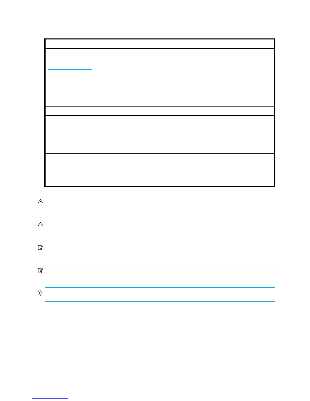
Document conventions and symbols
Table 1 Document conventions
Convention Element
Medium blue text: Figure 1 Cross-reference links and e-mail addresses
Medium blue, underlined text
(http://www.hp.com)
Bold font • Key names
Italics font Text emphasis
Monospace font • File and directory names
Monospace, italic font
Monospace, bold font Emphasis of file and directory names, system output, code, and text
Web site addresses
• Text typed into a GUI element, such as into a box
• GUI elements that are clicked or selected, such as menu and list
items, buttons, and check boxes
• System output
• Code
• Text typed at the command-line
• Code variables
• Command-line variables
typed at the command line
WARNING! Indicates that failure to follow directions could result in bodily harm or death.
CAUTION: Indicates that failure to follow directions could result in damage to equipment or data.
IMPORTANT: Provides clarifying information or specific instructions.
NOTE: Provides additional information.
TIP: Provides helpful hints and shortcuts.
12

Rack stability
WARNING! To reduce the risk of personal injury or damage to equipment:
• Extend leveling jacks to the floor.
• Ensure that the full weight of the rack rests on the leveling jacks.
• Install stabilizing feet on the rack.
• In multiple-rack installations, secure racks together.
• Extend only one rack component at a time. Racks may become unstable if more than one component is
extended.
HP technical support
Telephone numbers for worldwide technical support are listed on the HP support web site:
http://www.hp.com/support/
Collect the following information before calling:
• Technical support registration number (if applicable)
• Product serial numbers
• Product model names and numbers
• Applicable error messages
• Operating system type and revision level
• Detailed, specific questions
.
For continuous quality improvement, calls may be recorded or monitored.
Customer self repair
HP customer self repair (CSR) programs allow you to repair your StorageWorks product. If a CSR part
needs replacing, HP ships the part directly to you so that you can install it at your convenience. Some parts
do not qualify for CSR. Your HP-authorized service provider will determine whether a repair can be
accomplished by CSR.
For more information about CSR, contact your local service provider. For North America, see the CSR
website:
http://www.hp.com/go/selfrepair
Product warranties
For information about HP StorageWorks product warranties, see the warranty information website:
http://www.hp.com/go/storagewarranty
Subscription service
HP strongly recommends that customers sign up online using the Subscriber's choice web site:
http://www.hp.com/go/e-updates
• Subscribing to this service provides you with e-mail updates on the latest product enhancements, newest
versions of drivers, and firmware documentation updates as well as instant access to numerous other
product resources.
• After signing up, you can quickly locate your products by selecting Business support and then Storage
under Product Category.
.
HP web sites
For other product information, see the following HP web sites:
• http://www.hp.com
HP StorageWorks 2000sa G2 Modular Smart Array User Guide 13

• http://www.hp.com/go/msa
• http://www.hp.com/service_locator
• http://www.hp.com/go/storage
• http://www.hp.com/support/
• http://www.docs.hp.com
Documentation feedback
HP welcomes your feedback.
To make comments and suggestions about product documentation, please send a message to
storagedocs.feedback@hp.com. All submissions become the property of HP.
14
1Overview
The 2312sa G2 Modular Smart Array and 2324sa G2 Modular Smart Array are high-performance storage
solutions that combine outstanding performance with high reliability, availability, flexibility, and
manageability.
Features and benefits
Product features and supported options are subject to change. Therefore, web site postings document
product and product family characteristics, including currently supported features, options, technical
specifications, configuration data, related optional software, and product warranty information.
NOTE: Check the QuickSpecs for a complete list of supported servers, operating systems, disk drives, and
options. QuickSpecs can be found from your HP MSA products page at http://www.hp.com/go/msa
Select MSA SAN Arrays, and then select your product. The link for QuickSpecs will be on the right.
.
HP StorageWorks 2000sa G2 Modular Smart Array User Guide 15

16 Overview
2Components
MSA2000
132
4
5
6
MSA2000
132
4
5
6
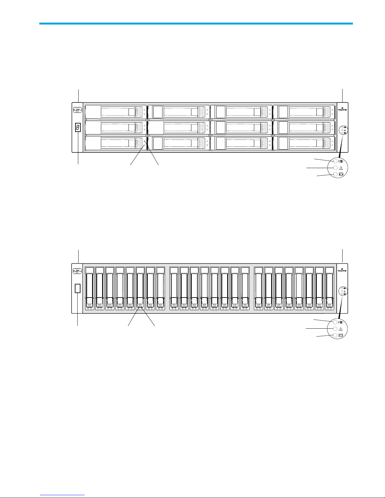
Front panel components
2312sa G2
Left ear
1 Enclosure ID LED
2 Disk drive Online/Activity LED
3 Disk drive Fault/UID LED
2324sa G2
Left ear
Right ear
4 Unit Identification (UID) LED
5 Fault ID LED
6 Heartbeat LED
Right ear
1 Enclosure ID LED
2 Disk drive Online/Activity LED
3 Disk drive Fault/UID LED
4 Unit Identification (UID) LED
5 Fault ID LED
6 Heartbeat LED
HP StorageWorks 2000sa G2 Modular Smart Array User Guide 17
Disk drive bay numbers
MSA2000
1
2
3
4
5
6
7
8
9
10
11
12
MSA2000
1 2 3 4 5 6 7 8 9 10111213141516 1718192021222324
SAS 3 SAS 4
SAS 1 SAS 2
LINK
ACT
LINK
ACT
LINK
ACT
LINK
ACT
SAS 3 SAS 4
SAS 1 SAS 2
LINK
ACT
LINK
ACT
LINK
ACT
LINK
ACT
12 34567 1
9
2
8
-
2312sa G2
2324sa G2
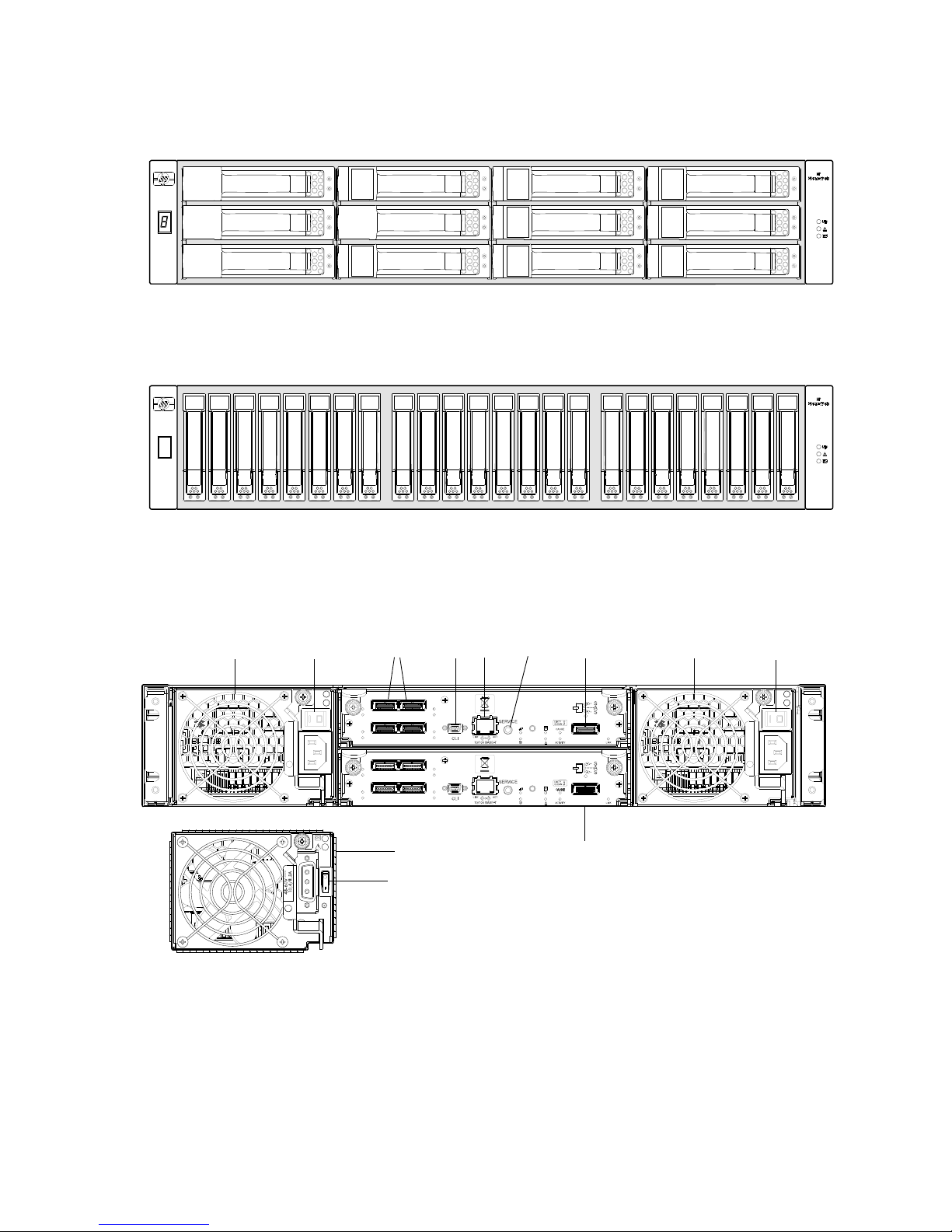
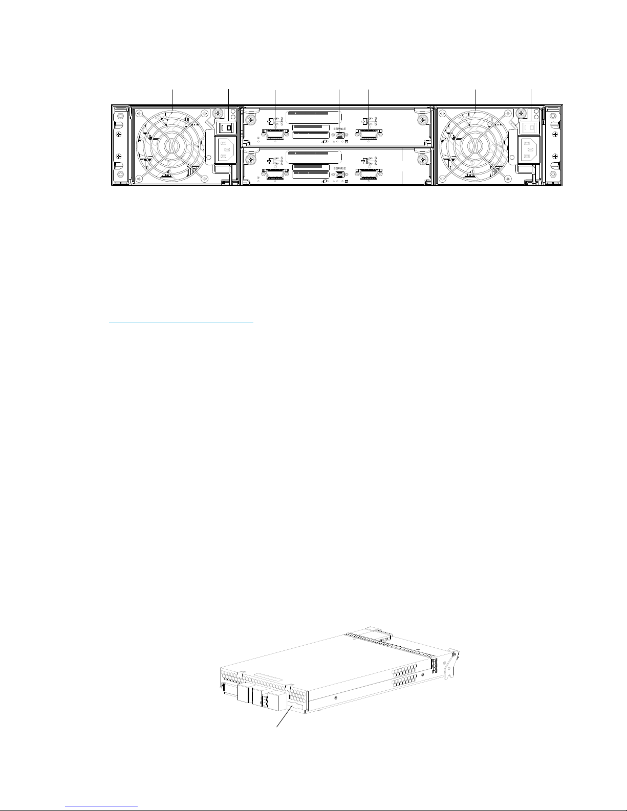
Rear panel components
2312sa G2 and 2324sa G2
1 AC Power supplies
2 AC Power switches
3 Host ports
4 CLI port
5 Network port
18 Components
6 Service port (used by service personnel only)
7 Expansion port
8 Optional SAS controller
9 DC Power supply (2) — (DC model only)
10 DC Power switch
MSA2000 3.5" 12-drive enclosure
00
13452
6
12
CompactFlash
Controller Module
1 Power supplies
2 Power switches
3 SAS In port (connects to a controller enclosure)
MSA70 2.5” 25-drive enclosure
The 2324sa G2 can also be attached to an MSA70 that is running firmware version 2.18 or later. For
information about the MSA70, see the HP StorageWorks 70 Modular Smart Array Enclosure user guide
located on the MSA2000 Software Support/Documentation CD shipped with your product or at
http://hp.com/support/manuals
.
Cache
To enable faster data access from disk storage, the following two types of caching are performed:
• Posted-write caching. The controller writes user data in the cache memory on the module rather than
directly to the drives. Later, when the storage system is either idle or aging — and continuing to receive
new I/O data — the controller writes the data to the drive array.
• Read-ahead caching. The controller detects sequential array access, reads ahead into the next
sequence of data, and stores the data in the read-ahead cache. Then, if the next read access is for
cached data, the controller immediately loads the data into the system memory, avoiding the latency of
a disk access.
Transportable CompactFlash
During a power loss or array controller failure, data stored in cache are saved off to non-volatile memory
(CompactFlash). These data are then written to disk after the issue is corrected. To protect against writing
incomplete data to disk, the image stored on the CompactFlash is verified before committing to disk.
4 Service port (used by service personnel only)
5 SAS Out port (connects to another drive enclosure)
6 Optional I/O module
In single-controller configurations, if the controller has failed or does not start, and the Cache Status LED is
on or blinking, the CompactFlash will need to be transported to a replacement controller to recover data
not flushed to disk. (See Controller failure in a single-controller configuration on page 56 for more
information.)
HP StorageWorks 2000sa G2 Modular Smart Array User Guide 19

CAUTION: To preserve the existing data stored in the CompactFlash, you must transport the
CompactfFlash from the failed controller to the replacement controller using a procedure outlined in the HP
StorageWorks 2312sa/2324sa G2 controller replacement instructions, shipped with the replacement
controller. Failure to use this procedure will result in the loss of data stored in the cache module. The
CompactFlash must stay with the same enclosure. If the CompactFlash is used/installed in a different
enclosure, data loss/data corruption will occur.
IMPORTANT: In dual controller configurations, there is no need to transport a failed controller’s cache to
a replacement controller because the cache is duplicated between the controllers.
Super-capacitor pack
To protect RAID controller cache in case of power failure, the 2312sa G2 and 2324sa G2 are equipped
with super-capacitor technology, in conjunction with CompactFlash memory, built into each controller
module to provide unlimited cache memory backup time. The super-capacitor pack and CompactFlash
memory in each controller module provide unlimited cache memory backup time. The super-capacitor pack
provides energy for backing up unwritten data in the write cache to the CompactFlash in the event of a
power failure. Unwritten data in CompactFlash memory is automatically committed to disk media when
power is restored. While the cache is being maintained by the super-capacitor, the Cache Status LED
flashes at a rate of 1/10 second on and 9/10 second off.
20 Components
3Installing the enclosures
Installation checklist
The following table outlines the steps required to install the enclosures and initially configure the system. To
ensure a successful installation, perform the tasks in the order they are presented.
Table 2 Installation checklist
Step
1.
2. Connect controller enclosure and LFF/SFF
3. Connect power cords. See the installation poster.
4. Test enclosure connections. See Testing enclosure
5. Obtain IP values and set management
6. Install required host software. See Host system requirements on
7. Connect data hosts. See Connecting the enclosure to
8. Connect remote management hosts. See Connecting remote
9. Perform initial configuration tasks:
Task Where to find procedure
Install the controller enclosure and optional
drive enclosures in the rack, and attach ear
caps.
drive enclosures.
port IP properties on the controller
enclosure.
See the racking instructions
poster.
See Connecting controller and
drive enclosures on page 22.
connections on page 26.
See Obtaining IP values on
page 27.
page 31.
data hosts on page 31.
management hosts on page 34.
• Verify that controllers and enclosures
have the latest firmware.
• Set the date and time on the controller
enclosure.
• Initially configure and provision the
system.
• Test the configuration. See Testing the configuration on
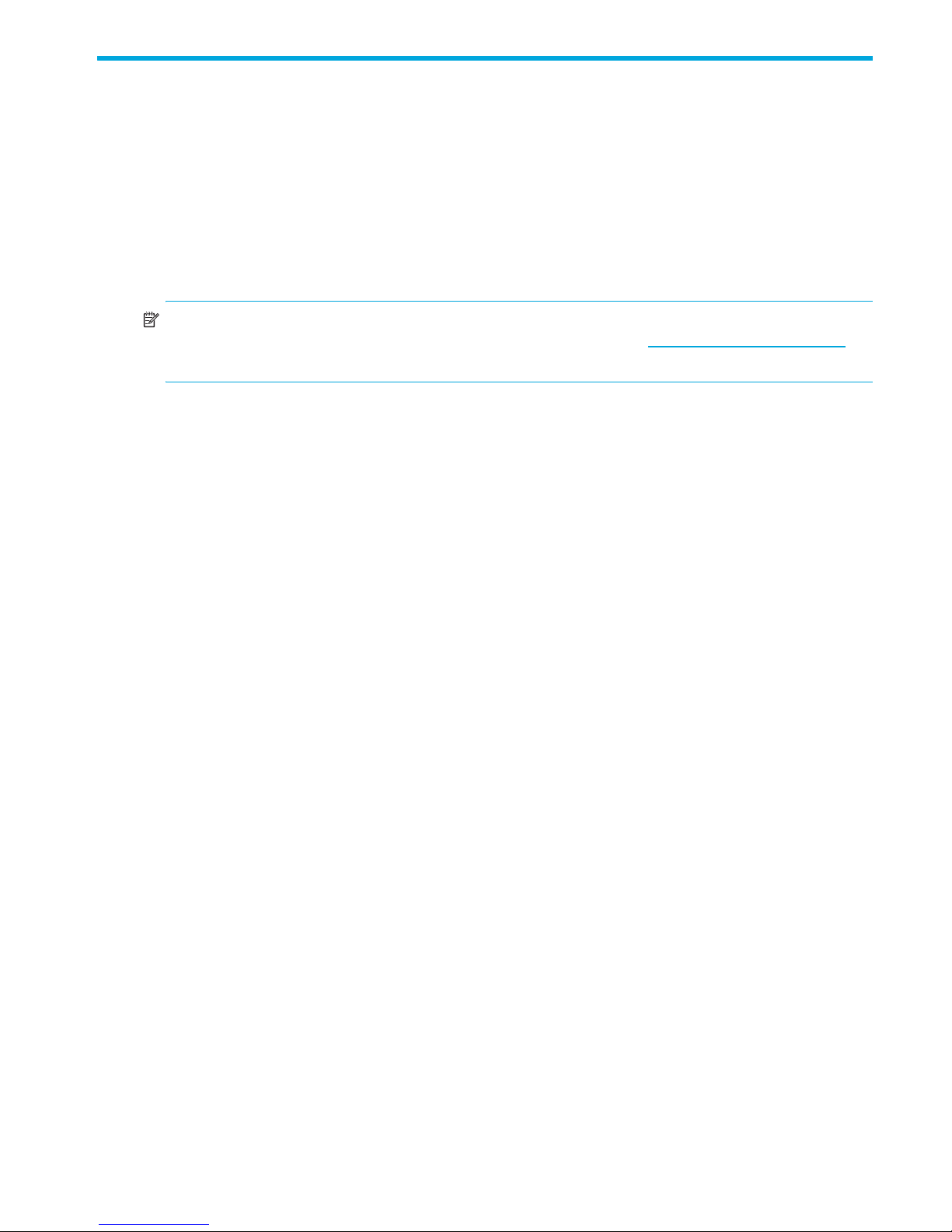
NOTE: For help with installing your MSA2000 G2 product, see the HP StorageWorks 2000 Modular
Smart Array Software Support/Documentation CD shipped with your product.
NOTE: For information on NEBS Level-3 compliant carrier-grade enclosures, see
http://www.hp.com/products1/servers/carrier_grade/products/cgblades/enclosure
See Updating firmware on
page 35.
See Changing the system date
and time on page 46.
See Using the Configuration
Wizard on page 48 and Using
the Provisioning Wizard on
page 49.
page 49.
.
HP StorageWorks 2000sa G2 Modular Smart Array User Guide 21

Connecting controller and drive enclosures
Connecting controller and MSA2000 3.5" 12-drive enclosures
You can connect up to four MSA2000 3.5" 12-drive enclosures to a 2312sa G2 and up to three MSA2000
3.5" 12-drive enclosures to a 2324sa G2. The cabling diagrams shown in this section show the
recommended fault-tolerant cabling patterns. Connecting an MSA2000 3.5" 12-drive enclosure to a
2312sa G2 or 2324sa G2 requires mini-SAS to SAS cables.
IMPORTANT: Adding a fourth drive enclosure to a 2312sa G2 may require a separate, longer cable. For
a current list of supported cables, check the MSA2000 G2 QuickSpecs located on the HP MSA products
page at http://www.hp.com/go/msa
QuickSpecs link is located on the right.
When connecting multiple drive enclosures, use reverse cabling to ensure the highest level of fault
tolerance. Controllers and I/O (expansion) modules are identified by
<enclosure-ID><controller-ID>. For example, Figure 3 on page 24 shows controller 1A
connected to I/O module 2A, and the chain of connections continuing down. Controller 1B is connected
to the lower module (B) of the last drive enclosure in the chain, with connections moving in the opposite
direction.
Connecting controller and MSA70 2.5” 25-drive enclosures
The 2324sa G2 can also be attached to an MSA70 running firmware version 2.18 or later. For information
about the MSA70, including detailed steps to upgrade the firmware, see the HP StorageWorks 70 Modular
Smart Array Enclosure User Guide located on the MSA2000 Software Support/Documentation CD
shipped with your product, or at http://hp.com/support/manuals
. Select MSA SAN Arrays, and then select your product. The
.
Connecting controller and mixed-connect 3.5” and 2.5” drive enclosures
You can connect LFF MSA2000 3.5" 12-drive enclosures and SFF MSA70 2.5” 25-drive enclosures to a
2324sa G2 controller enclosure in mixed-connect fashion, as shown in Figure 6 on page 26, and as
further described in the following documents:
• HP StorageWorks MSA2000 G2 Installation Instructions
• HP StorageWorks 2000 G2 Modular Smart Array Cable Configuration Guide
These documents also address connection of the controller enclosure to either LFF or SFF drive enclosures.
A few sample connection diagrams are provided in Figures 1-5 on the following pages.
Additional cable requirements for drive enclosures
IMPORTANT:
• When installing SAS cables, only use supported SAS 4x cables with 3Gb connectors.
• SAS to SAS 0.6m cables are provided for the MSA2000 3.5" 12-drive enclosure (one per controller).
• Mini-SAS to mini-SAS 0.5m cables are provided with the MSA70 drive enclosure (one per controller).
• The maximum cable length allowed in any configuration is 2m.
• If additional or longer cables are required, they must be ordered separately (see MSA2000 G2 Quick
Specs).
• When expanding storage capacity, a maximum of five enclosures
ninety-nine (99) disk drives are allowed in the array.
—including the array enclosure— or
2312sa G2 and 2324sa G2 cable requirements
The table below provides SAS cable requirements for connection combinations between MSA controllers
and drive enclosures.
22 Installing the enclosures
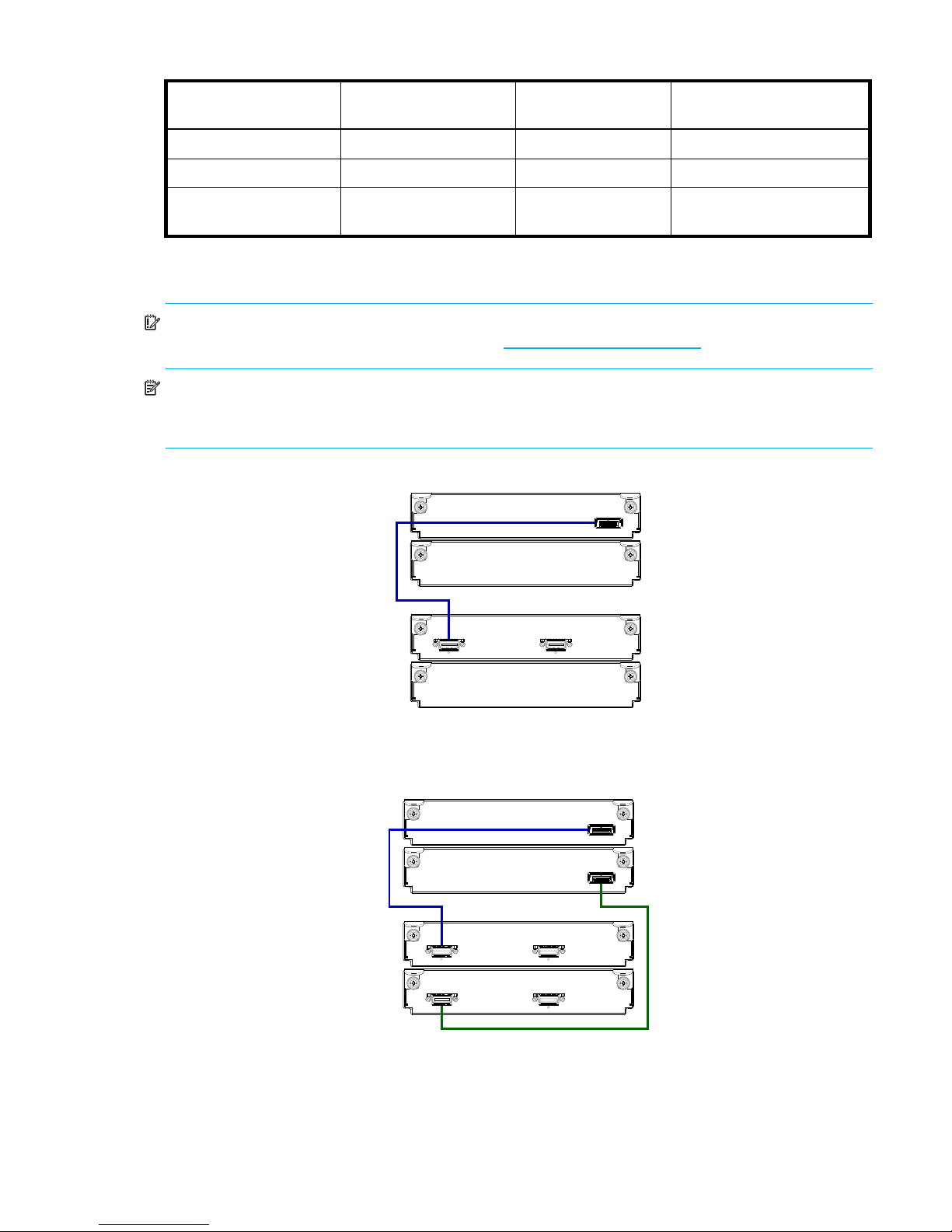
Table 3 SAS cable requirements
In Out
1B
1A
2A
2B
Controller A
In Out
1B
1A
2A
2B
Controller A
Controller B
In Out
Item MSA2000 G2 controller MSA70 I/O module MSA2000 3.5” 12-drive
I/O module
MSA2000 G2 controller
MSA70 I/O module
MSA2000 3.5” 12-drive
N/A mini-SAS to mini-SAS mini-SAS to SAS
mini-SAS to mini-SAS mini-SAS to mini-SAS mini-SAS to SAS
mini-SAS to SAS mini-SAS to SAS SAS to SAS
I/O module
Mini-SAS to SAS cables must be purchased separately.
0.5m cables are recommended for mini-SAS to SAS connections and mini-SAS to mini-SAS connections, respectively.
IMPORTANT: For a complete list of supported cables, cable part numbers, available options, and cabling
illustrations, see the MSA2000 G2 QuickSpecs at http://www.hp.com/go/msa
.
NOTE: For clarity, the schematic illustrations of the controllers shown in this section provide only relevant
details such as generic expansion ports. For detailed illustrations showing all components, see Rear panel
components on page 18.
Figure 1 Cabling connections between a single-controller enclosure and one MSA2000 3.5" 12-drive
enclosure
Figure 2 Cabling connections between a dual-controller enclosure and one MSA2000 3.5" 12-drive
enclosure
HP StorageWorks 2000sa G2 Modular Smart Array User Guide 23
 Loading...