

Page 1

HP StorageWorks 1000i Virtual Library System
user guide
406685-002
Part number: 406685-002
Second edition: October 2006
Page 2

Legal and notice information
© Copyright 2006 Hewlett-Packard Development Company, L.P.
Hewlett-Packard Company makes no warranty of any kind with regard to this material, including, but not limited to, the implied
warranties of merchantability and fitness for a particular purpose. Hewlett-Packard shall not be liable for errors c ontained herein or
for incidental or consequential damages in connection with the furnishing, performance, or use of this material.
This document contains proprietary information, which is protected by copyright. No part of this document may be photocopied,
reproduced, or translated into another language without the prior written consent of Hewlett-Packard. The information is provided
“as is” without warranty of any kind and is subject to change without notice. The only warranties for HP products and services are
set forth in the express warranty statements accompanying such products and services. Nothing herein should be construed as
constituting an additional warranty. HP shall not be liable for technical or editorial errors or omissions contained herein.
Adobe® and Acrobat® are trademarks of Adobe Systems Incorporated.
Intel and Itanium are trademarks or registered trademarks of Intel Corporation or its subsidiaries in the United States and other
countries.
Microsoft®, Windows®, Windows NT®, and Windows® XP are U.S. registered trademarks of Microsoft Corporation.
UNIX® is a registered trademark of The Open Group.
Printed in the US.
Page 3

Contents
Aboutthisguide .......................... 11
Intendedaudience...................................... 11
Prerequisites ........................................ 11
Relateddocumentation.................................... 11
Documentconventionsandsymbols ............................. 12
Rackstability ....................................... 12
HPtechnicalsupport.................................... 13
Subscriptionservice .................................... 13
HP-authorizedresellers ................................... 13
HPwebsites ....................................... 13
Documentationfeedback .................................. 13
1Introduction............................ 15
Features ......................................... 15
Benefits ......................................... 15
Importantconcepts..................................... 16
InternetSCSI(iSCSI)protocol .............................. 16
Disk-to-Disk-to-Tape(D2D2T)backupcapabilities...................... 16
RedundantArrayofIndependentDisks(RAID) ....................... 16
Emulation....................................... 17
Retentionplanning..................................... 17
2SettinguptheVLS1000ihardware................. 19
Preparingfortheinstallation................................. 19
Toolsforinstallation .................................. 19
TakingESDprecautions................................. 19
Selectingalocation .................................... 19
Unpacking ........................................ 20
Racking(optional)..................................... 21
Optimumenvironmentforarackedsystem(optional) .................... 22
Space and airflowrequirements........................... 22
Temperaturerequirements.............................. 23
Powerrequirements ................................ 23
Electricalgroundingrequirements .......................... 23
InstallingtheVLS1000inodeintoarack(optional) ..................... 24
Installrailsintherack ............................... 24
Attach rails to the VLS1000i (appliance) . . . . . . . . . . . . . . . . . . . . . . . . 26
Installapplianceinrack .............................. 26
InstallingVLS1000icables ................................. 28
3 ConfiguringtheVLS1000i ..................... 31
Reviewingpre-installationrequirements ............................ 31
iSCSIinitiators .................................... 31
Browser ....................................... 31
VerifyingthesettingsinInternetExplorer ....................... 31
VerifyingthesettingsinFirefox............................ 33
PoweringontheVLS.................................... 35
ConfiguringtheVLS .................................... 35
Recording the network configuration ........................... 36
HP StorageWorks 1000i Virtual Library System
3
Page 4

ConfiguringtheVLSappliancewiththeVLSDiscoverytool.................. 36
ConfiguringtheVLSapplianceviathedefaultIPAddress .................. 38
Verifying the network configuration............................ 38
Entering the system configuration............................. 40
Configuringsysteminformation ........................... 41
Configuringlogoninformation............................ 41
ConfiguringE-mailalerts .............................. 42
Settingthetimeanddateinformation......................... 43
DeployingiSCSIinitiators................................ 43
ObtainingiSCSIaddressfromhost............................ 45
Creatingvirtualdevices................................... 47
Creatingastandalonetapedevice............................ 47
Creatingatapelibrary................................. 48
Connectingdevices(targets)tobackuphosts(initiators) ..................... 50
4WorkingwiththeVLS1000i.................... 53
Loggingonfromanysystemwithnetworkaccess........................ 53
Understanding the Configurationpage ............................ 54
ReviewingtheBackupHostSummarypage ........................ 54
UnderstandingtheView/EditVirtualLibrarypage ..................... 55
LoggingoffoftheVLSGUI ............................... 57
Understandinghowdynamictapedeviceswork ........................ 57
Checkingcommunicationwithotherappliancesorsystems.................... 57
RefreshingtheVLSGUIdisplay ............................... 58
Relocatinganappliance .................................. 59
RebootingtheVLS..................................... 61
PoweringofftheVLS.................................... 62
5 VLS1000i GUI . . . . . .................... 63
Windowregions...................................... 63
OpeningaVLSGUIsessionfromawebbrowser........................ 64
ClosingaVLSGUIsession ................................. 65
VLSGUItabs ....................................... 65
VLSIdentitytab .................................... 65
Configurationtab ................................... 66
CreateVirtualDevice................................ 66
View/EditVirtualLibrary .............................. 66
View/EditVirtualStandaloneTape.......................... 68
BackupHostSummary ............................... 69
HardwareStatus.................................. 69
Network Configuration............................... 70
System Configuration................................ 70
Supporttab...................................... 71
SoftwareUpdate ................................. 71
Save/Restore Configuration............................. 71
SupportTicket................................... 71
PingHost..................................... 72
ShutDown/Restart................................. 72
VLS1000iHelp .................................. 72
SupportLinks ................................... 72
6Maintenance.......................... 73
Operationalmaintenance.................................. 73
ListofE-mailalerts................................... 73
Log files ....................................... 74
Configuration files................................... 75
Singledrivefailure................................... 76
Non-operationaldiagnosticsandrecovery........................... 77
4
Page 5

Multipledrivefailure.................................. 77
Firmwarecorruption .................................. 77
Fatalhardwarefailure ................................. 78
Appliancereplacement................................. 78
UsingtheDiagnostic/QuickRestoreCD............................ 78
7Componentreplacement..................... 83
Safetyconsiderations.................................... 83
Groundingmethodstopreventelectrostaticdamage .................... 83
Warningsandcautions................................. 83
Chassiscovers ...................................... 84
Reartopcover .................................... 84
Fronttopcover .................................... 85
Backplanebattery................................... 88
Systemmemory .................................... 89
Systemfans...................................... 91
Harddiskdrives.................................... 92
RAIDcontrollercard .................................. 94
DVD-ROMdrive.................................... 95
A Specifications.......................... 97
VLS1000i node specifications................................ 97
System specifications.................................... 97
Electrical specifications................................... 97
Physical specifications ................................... 98
Environmental specifications................................. 98
B Troubleshooting . . . . ..................... 99
TheVLSisoperational,butinaccessible............................ 99
Internet Explorer does not redirect from IP address on Windows Server 2003 . . . . . . . . . . . . 99
Clickingsubmitinvokesarefresherrormessageorreceivesnoresponse.............. 101
ReceiveerrormessagePageNotFound(HTTP500InternalServerError).............. 103
UnabletologontotheGUI................................. 103
The system has reached, or will not exceed, a limit or capacity . . . . . . . . . . . . . . . . . . 104
ReceiveSystemLogoutmessage ............................... 104
Receiveperpetualloopofaudioalerts ............................ 104
CRegulatorycomplianceandsafety................. 105
Regulatory compliance identificationnumbers ......................... 105
FederalCommunicationsCommissionnotice.......................... 105
ClassAequipment................................... 105
ClassBequipment................................... 106
Declaration of conformity for products marked with the FCC logo, United States only . . . . . . . 106
Modifications..................................... 106
Cables........................................ 106
Lasercompliance ..................................... 107
Internationalnoticesandstatements ............................. 107
Canadiannotice(AvisCanadien) ............................ 107
ClassAequipment................................. 107
ClassBequipment................................. 107
EuropeanUnionnotice................................. 107
BSMInotice...................................... 108
Japanesenotice.................................... 108
Koreannotice(A&B).................................. 108
Safety .......................................... 109
Batteryreplacementnotice ............................... 109
Taiwanbatteryrecyclingnotice ........................... 109
HP StorageWorks 1000i Virtual Library System
5
Page 6

Powercords...................................... 109
Japanesepowercordnotice............................... 109
Electrostaticdischarge ................................. 109
Preventingelectrostaticdischarge........................... 110
Groundingmethods ................................ 110
WasteElectricalandElectronicEquipmentdirective....................... 110
Czechoslovakiannotice................................. 110
Danishnotice..................................... 111
Dutchnotice ..................................... 111
Englishnotice..................................... 111
Estoniannotice .................................... 111
Finnishnotice..................................... 112
Frenchnotice ..................................... 112
Germannotice .................................... 112
Greeknotice ..................................... 112
Hungariannotice ................................... 113
Italiannotice ..................................... 113
Latviannotice..................................... 113
Lithuaniannotice ................................... 113
Polishnotice ..................................... 114
Portuguesenotice ................................... 114
Slovakiannotice.................................... 114
Sloveniannotice.................................... 114
Spanishnotice .................................... 115
Swedishnotice .................................... 115
Glossary............................. 117
Index .............................. 121
6
Page 7

Figures
1
..
2
..
3
..
4 ..
5
..
6
..
7
..
8
..
9
..
10
..
11
..
12
..
13
..
..
14
15
..
16
..
17
..
18
..
19
..
20
..
21
..
22
..
23
..
24
..
25 ..
26
..
27
..
28
..
29
..
30
..
31
..
32
..
33
..
34 ..
35
..
36
..
37
..
38
..
39
..
40
..
..
41
42
..
43
..
Disk-to-Disk-to-Tapebackup............................ 16
VLS1000inodeshippingcartoncontents...................... 21
Install sem
InsertM5screw ................................ 25
Installrails................................... 25
Removeslidesfromrails............................. 26
Attachslidestoappliance............................ 26
Insertapplianceintorack ............................ 27
Secureappliancetotherack........................... 27
Appliancerearview .............................. 28
Push pow
Attachbezel.................................. 29
CustomlevelonSecuritytab........................... 32
SecuritySettings ................................ 32
Privacysetting................................. 33
Allowcookies ................................. 34
Webfeaturessettings.............................. 35
Presspowerbutton............................... 35
Scanningfordevices .............................. 36
VLSdiscoveryutility–mainwindow........................ 37
VLS discovery utility – Device Configurationwindow................. 37
Updating configuration ............................. 38
Releasingdevices ............................... 38
LogontotheVLS................................ 39
VLSGUI ................................... 39
Select Network Configurationonmenu ...................... 40
Select System Configuration ........................... 41
SystemInformationsettings............................ 41
Settinglogininformation............................. 42
E-mail Notifi
Set t
iSCSIinitiatorproperties............................. 45
iSCSIInitiatorProperties............................. 46
HostSettings.................................. 46
iSCSIName.................................. 47
Selecttypeofdevicetocreate .......................... 47
Creatingatapedevice ............................. 48
Creatingatapelibrary ............................. 49
Ready to findtargets .............................. 50
Targetsfound ................................. 51
Logontotarget ................................ 51
VLSGUIloginwindow ............................. 53
VLSGUIIdentitypage.............................. 54
i-piercedwashersintorack ....................... 24
erbutton ............................... 29
cationsettings............................ 43
imeanddate ............................... 43
HP StorageWorks 1000i Virtual Library System
7
Page 8

44
..
BackupHostSummarypage........................... 55
45
..
View/EditVirtualLibrarypage.......................... 56
..
Pingpage................................... 58
46
47
..
Pingresultsmessages.............................. 58
48
..
Connectedtargets ............................... 59
49
..
Logoffsessions ................................ 60
50
..
ShutDown/Restartpage............................. 60
51
..
Shut down confirmation............................. 61
52
..
ShutdownandrestarttheVLS .......................... 62
53
..
GUIwindowregions .............................. 64
54
..
VLS GUI logi
55
..
Select log files................................. 75
56
..
Save configuration file ............................. 75
57
..
Created filemessagewindow .......................... 76
58
..
Download c
59
..
Save the configuration file............................ 76
60
..
FrontpanelLEDsandbuttons........................... 79
61
..
Removingreartopcover............................. 84
62
..
Sliding o
63
..
Tightenreartopcoverscrew........................... 85
64
..
Loosenfronttopcoverscrews........................... 86
65
..
Slidingofffronttopcover ............................ 87
66
..
Slidingonfronttopcover ............................ 87
67
..
Tightenfronttopcoverscrews .......................... 88
68
..
Backplanebatterylocation............................ 88
69
..
Removingbackplanebattery........................... 88
70
71
72
73
74
75
76
77
78
79
80
81
82
83
84
85
86
87
88
89
90
91
lingbackplanebattery ........................... 89
..
Instal
..
LocationofDIMMsockets ............................ 89
..
DIMMmap .................................. 90
..
RemovingaDIMM ............................... 90
..
..
..
..
..
..
..
..
..
..
..
..
..
..
..
..
..
..
kretainingclips.............................. 91
Unloc
InsertingDIMMintosocket............................ 91
Locationofsystemfans ............................. 91
Systemfancables ............................... 92
ingoutfan ................................. 92
Lift
LocationofHDDs................................ 93
ReleasingHDDlever .............................. 93
SlidingHDDfrombay.............................. 93
RemovingHDDfromtray ............................ 94
Removingrisercardassembly .......................... 94
Removingcontrollercardfromrisercardassembly.................. 95
RemovedDVD-ROMscrews ........................... 95
LiftingtheDVD-ROMoutoftheVLS ........................ 95
RemovingtheDVD-ROMconnectorplate...................... 95
I.E.Securitytabwindow............................. 100
AddTrustedsiteswindow ............................ 100
I.E.SecurityTabWindow—CustomLevel ..................... 101
Securitysettings—enable............................ 102
nwindow ............................. 65
onfiguration file ........................... 76
nreartopcover ............................ 85
8
Page 9

92
..
EnablingJavaandJavaScript .......................... 103
HP StorageWorks 1000i Virtual Library System
9
Page 10

Tables
1
2
3
4
5
6
7
8
9
10
11
..
Documentconventions.............................. 12
..
Network con figuration ............................. 36
..
Hardwarestatusindicators............................ 69
..
E-mailmessages ................................ 74
..
Diagnosticsmessages.............................. 80
..
PopulatingtheDIMMsockets........................... 90
..
VLS1000i no
..
System specifications .............................. 97
..
Electrical specifications ............................. 97
..
Physical specifications.............................. 98
..
Environmental specifications ........................... 98
de specifications .......................... 97
10
Page 11

About this guid e
This guide provides information that helps you:
• Become familiar with HP StorageWorks 1000i virtual library system (VLS) features, models,
and
components
• Install and operate your VLS
• Configure your VLS to meet the data backup needs of your environment
• Manage your VLS so that it continues to meet the data backup needs of your environment
• MonitoryourVLS’s hardware status
• Replace failed customer-replaceable c omponents
• Troubleshoot problems
• Perform diagnostics and disaster recovery
Intended au
This book is intended for use by system administrators who are experienced with setting up and managing
system backups over a Local Area Network (LAN).
dience
Prerequisites
Before beginning, make sure you are familiar with the items below.
• Tape backup technologies, tape libraries, and backup software
• LAN environments
Before installing the appliance, make sure you have:
• APhillipsscrewdriver.
• If racking is desired, an HP 1 0000 Series rack with one unit of space available to mount a VLS.
Other racks might also be suitable, but have not been tested with the VLS.
Related documentation
In addition to this guide, please refer to other documents for this product:
• HP Storag
• HP StorageWorks 1000i Virtual Library System parts replacement poster
These and other HP documents can be found on the HP documents web site: h
support/.
eWorks 1000i Virtual Library System installation instructions poster
ttp://www.hp.com/
HP StorageWorks 1000i Virtual Library System
11
Page 12
Document conventions and symbols
conventions
Table 1 Documen
t
Convention
Blue text: Table 1
Blue, underlined text: http://
www.hp.com
Bold text
Italic text Text emphasis
Monospace text
Monospace, italic text
Monospace, bold text
Element
Cross-reference links and E-mail
addresses
Web site addresses
• Keys that are pressed
Text typed into a GUI element, such
•
as a
box
• GUI
• File and directory names
•
•
•
• Code variables
•
Emphasized monospace text
elements that a re clicked or
selected, such as menu and list
items, buttons, tabs, and check
boxes
System output
Code
Commands, their arguments, and
argument values
Command variables
WARNING!
Indicates that failure to follow directions could result in bodily harm or death.
CAUTION:
Indicates that failure to follow directions could result in damage to equipment or data.
NOTE:
Provides additional information.
Rack stability
WARNING!
If your appliance is in a rack, reduce the risk of personal injury or damage to equipment:
• Extend leveling jacks to the floor and ensure that the full weight of the rack rests on the leveling jacks.
• Install stabilizing feet on the rack.
• In multiple-rack installations, secure racks together.
• Extend only one rack component at a time. Racks may become unstable if more than one component
is
extended.
12
About this guide
Page 13

HP technical su
pport
Telephone numb
ttp://www.hp.com/support/.
h
Collect the following information before calling:
• Technical sup
• Product serial numbers
• Product model names and numbers
• Error messag
• Operating system type and revision level
• Detailed questions
• Support tick
For continuous quality improvement, calls may be recorded or monitored.
ers for worldwide technical support are listed on the HP support web site:
port registration number (if applicable)
es
et
Subscription service
HP recommends that you register your product at the Subscriber’s Choice for Business web site:
h
ttp://www.hp.com/go/e-updates.
After registering, you will receive E-mail notification of product enhancements, new driver versions,
firmware updates, and other product resources.
HP-author
ized resellers
For the name of your nearest HP-authorized reseller:
• In the United States, call 1-800-282-6672.
visit the HP web site: h
• Elsewher
telephone numbers.
e,
ttp://www.hp.com.Then click Contact HP to find locations and
HP web sites
For additional information, see the following HP web sites:
ttp://www.hp.com
• h
• http://www.hp.com/go/storage/tapestorage
• http://www.hp.com/support/
• http://www.docs.hp.com
Documentation feedback
your feedback.
HP welco
To make comments and suggestions about product documentation, please send a message to
storagedocs.feedback@hp.com. All submissions become the property of HP.
mes
HP StorageWorks 1000i Virtual Library System
13
Page 14

14
About this guide
Page 15

1Introduction
This section describes the HP StorageWorks 1000i virtual library system features, m odels, and c oncepts.
Features
The HP StorageWorks 1000i virtual library system ( VLS) is a RAID 5, serial ATA disk-based LAN backup
device that emulates standalone HP LT02 drives and HP Autoloader 1/8 with LT02 physical tape drives,
perform disk-to-virtual tape (disk-to-disk) backups using your existing backup applications.
allowing you t
The VLS emulat
and
number of tap
You configur
emulates up to 6 tape libraries, 12 tape drives, and 180 cartridges.
The VLS accommodates mixed IT platform a nd backup application environments, allowing all your servers
and
allowed to access each virtual library and tape drive you configure.
Benefits
Integrating a VLS into your existing storage and backup infrastructure delivers the following benefits:
• Faster backups
• Faster single file restores
• Lower operating costs
• More efficient use of storage space
cartridg
backup applications to access the virtual media simultaneously. You specify which servers are
The VLS is optimized for backups and delivers faster performance than a simple disk-to-disk
solution. The VLSemulatesmanymoretapedrivesthanare availableinphysicaltapelibraries,
allowing more hosts to run backups concurrently.
Asingle file can be restored much faster from disk than tape.
Fewer physical tape drives and cartridges are required as full backups to tape are
eliminated. Also, fewer cartridges are required as small backups stored on multiple virtual
cartridges can be copied to one physical cartridge.
Physical tape libraries cannot share storage space with other
physical tape libraries, and physical cartridges cannot share storage space with other physical
cartridges. This unused storage space is wasted.
Storage space is not wasted in a VLS, because VLS storage space is dynamically assigned as it is
used. Storage space is shared by all the libraries and cartridges confi gured on a VLS.
o
HP Autoloader 1/8 with LT02 physical tape libraries, including the tape drives
es the
inside the libraries. You determine the number of tape libraries a VLS emulates, and the
es
drives and cartridges included in each tape library to meet the needs of your environment.
e
the size of the virtual cartridges in your VLS, which provides even more flexibility. The VLS
e
• Reduced risk of data loss and aborted backups
RAID 5-based storage is more reliable than tape storage.
Aborted backups caused by tape drive mechanical failures are eliminated.
HP StorageWorks 1000i Virtual Library System
15
Page 16
Important concepts
To understand the configu ration of the backup network and how it fits into the local-area network (LAN),
review the following sections.
Internet SCSI (iSCSI) protocol
Internet SCSI (iSCSI) is a standard protocol for universal access to shared storage devices over standard,
Ethernet-based transmission control protocol/Internet protocol (TCP/IP) networks. The connection-oriented
protocol transports SCSI commands, data, and status across an IP network.
The iSCSI architecture is based on a client-server model. The client is a host system that issues requests
to
read or write data. iSCSI refers to a client as an initiator. The server is a resource that receives and
executes client requests. iSCSI refers to a server as a target.
File servers, which store the programs and data files sha red by users, normally play the role of server.
With the VLS, the application and backup servers within your network act as clients or initiators and
the
VLS acts as a server or target. The initiators can either be iSCSI software simulation or host bus
adapters (HBAs) on the ser ver that is b eing backed up.
Disk-to-Disk-to-Tape (D2D2T) backup capabilities
TheVLS is astorage resource used by asinglebackupserver orsharedby multiplebackupservers using
an Ethernet network. By using standard backup software, you can copy backup data that resides on the
VLS to physical tape for long-term data retention.
The following illustration shows application servers sending backup data over a Gigabit Ethernet (GbE)
LAN to b ackup servers sharing VLS D2D storage over GbE.
NOTE:
The con
Figure 1 Disk-to-Disk-to-Tape backup
In addition to being part of the LAN, the backup servers, and the VLS are part of the GbE backup LAN.
nection fr om the Client — Tape can be either FC or direct attached SCSI.
Clients
Ethernet
VLS 1000i Client Client - Tape
Redundant Array of Independent Disks (RAID)
RAID provides convenient, low-cost, reliable storage by saving data on more than one disk drive
simultaneously. If one disk drive in a RAID 5 configuration becomes unavailable, the others continue to
work in a degraded state, thus avoiding downtime for users.
16
Introduction
Page 17

Emulation
The VLS1000i can emulate:
• a standalone tape drive, with a 1:1 relationship between cartridges and drives
• a library, with
Both emulations are based on LTO-2 drive technology. When you use emulation, the disk drives on the
VLS appear to your backup software as LTO-2 tape cartridges, which simplifi es the setup process while
simultaneously providing data compression and the attributes of backing up data to disk.
NOTE:
Data compression can be used, but it reduces the data transfer speed significantly.
multiple
Retention planning
Retention planning and sizing go hand in hand. How long do you need to keep data on disk? How
many full backups do you want to keep on disk? How many incremental backups? How do you want to
optimize retention times of the VLS? Retention policies help you recycle virtual media. Bear the following
considerations in mind as you plan retention policies:
• If the data’s useful life is too short to warrant backup to tape, you might choose to keep it on disk.
• Once the retention period expires, the virtual media is automatically recycled (remember that you
never remove tapes from a virtual library so you want the backup application to keep re-using the
same virtual tapes based on their retention recycling periods).
• In your backup application you should set the tape expiration dates (that is, when the tape is
marked as worn out) high because virtual media does not wear out.
• Backup-job retention time is for virtual media.
• Copy-job retention time is for physical media.
• When copying through the backup application, the virtual and physical pieces of media are
tracked separately and the retention times should be considered and set individually.
cartridges and 1 or more drives
HP StorageWorks 1000i Virtual Library System
17
Page 18

18
Introduction
Page 19

2 Setting up the VLS1000i hardware
The hardware installation consists of these steps:
• Preparing for the installation
• Unpacking
• Racking (optional)
• Installing cables
Preparing for the installation
The following sections describe preparing for the installation.
Tools for installation
The following tools are required for the installation.
• Phillips screwdriver
• Box cutting knife
Taking ESD precautions
To prevent damaging the system, be aware of the precautions you need to follow when setting up the
system or handling parts. A discharge of static electricity from a finger or other conductor may damage
system boards or other static-sensitive devices. This type of damage may reduce the life expectancy of
the
device.
electrostatic damage:
To preven
• Avoid hand contact by transporting and storing products in static-safe containers.
• Keep electrostatic-sensitive parts in their containers until they arrive at static-free workstations.
• Place par
• Avoid touching pins, leads, or circuitry.
• Always be properly grounded when touching a static-sensitive component or assembly.
t
ts on a
grounded surface before removing them from their containers.
Selecting a location
When selecting a location, follow these guidelines:
• Select a location that is flat, sturdy, and level.
• Select a location close to a network Ethernet port and an AC outlet. The AC power cord is the
appliancet’s main AC disconnect device and must be easily accessible at all times.
• Ensure minimum clearance of 15.4 cm (6 inches) at the back of the appliance, 30.8 cm (12
inches) at the front of the appliance, and 5.08 cm (2 inches) on either side of the appliance.
• Avoid placing the autoloader on the floor or other carpeted surfaces.
• The appliance makes some noise when operating, so choose a location where the noise will
not
be cause a disturbance.
• Avoid areas near frequently used doors and walkways, stacks of supplies that collect dust,
printers, and smoke-filled rooms.
HP StorageWorks 1000i Virtual Library System
19
Page 20

CAUTION:
Excessive dust and debris can damage tapes and tape drives.
Do notplace theautoloaderonSee Environmental specifications for more information.
If
you will rack the appliance, see Optimum environment for a racked system (optional).
Unpacking
Place the shipping carton as close to the installation site as possible. Before unpacking the VLS, inspect
the
shipping carton for damage that may have occurred during shipment. If you detect any damage,
notify the carrier and HP before unpacking the unit.
To unpack the VLS:
1. Open the top of the shipping cartons.
2. Carefully lift the units out of the boxes and remove the packing materials.
3. Place the units on a stable work sur face.
NOTE:
Inspect the units for any damage that may have occurred during shipment. If damage is detected,
contact your authorized service representative.
4. Locate the m aterials and documentation necessary for installing the VLS (see Figure 2). All the
rack mounting hardware and documentation necessary for installing a VLS node into a rack is
included in thenodeshippingcarton.
20
Setting up the VLS1000i hardware
Page 21
1
2
3
Item
1
2
3
4
5
Description
VLS1000i
Bezel
Power cor
Slide rail assembly and
hardware
d
7
Item
5
6
7
Description
Bezel brackets and screws
Documentation CD,
Diagnostic/Quick Restore
CD, Firmware CD, Safety
guide
Data Protector Express
bundle
Figure 2 VLS1000i node shipping carton contents
5. Place shipping materials back into the shipping cartons.
4
6
5200b
Racking (optional)
Therackresourcekit shipswiththe rack. A summary of thecontent of each resource follows:
• Custom Builder is a web-based service for configuring one or many racks. Rack configurations
can
•A simple, guided interface
• Build-it-yourself model
• The In
config
confi
• Planning the site
• Installing rack servers and rack options
•Cabl
• Coupling multiple racks
• The Rack Products Documentation CD enables you to view, search, and print documentation for
HP
in a manner that best fits your environment.
reated using:
be c
stalling Rack Products video provides a visual overview of operations required for
uring a rack with rack-mountable components. It also provides the following important
guration steps:
servers in a rack
ing
Compaq branded racks and rack options. It also helps you set up and optimize a rack
nd
a
HP StorageWorks 1000i Virtual Library System
21
Page 22

WARNING!
To reduce the risk of personal injury or damage to the equipment, be sure that:
• Thelevelingjacks areextendedtothe floor and the full weight of the rack rests on the leveling jacks.
• The stabilizing feet are attached to the rack if it is a single-rack installation.
• The racks are coupled together in multiple-rack installations.
• Only one component is extended at a time. A rack may become unstable if more than one
component is extended for any reason.
WARNING!
To reduce the risk of p ersonal injury or equipment damage when unloading a rack:
• At least two people are needed to safely unload a rack from a pallet. An empty 42U rack can weigh
as much as
being moved on its casters.
• Never stand in front of a rack when it is rolling down the ramp from the pallet. Always handle a
rack from both sides.
115 kg (253 lb), can stand more than 2.1 m (7 ft) tall, and may become unstable when
Optimum environment for a racked system (optional)
When installing a VLS in a rack, select a location that meets the environmental standards described
in
this section and Environmental specifications.
Space and airflow requirements
To allow for servicing and adequate airflow, observe the following space and airflow requirements
where to install a rack:
when decid
• Leave a minimum clearance of 122 cm (48 in) in front of the rack.
• Leave a minimum clearance of 76.2 cm (30 in) behind the rack.
• Leave a mi
rack when racks are back-to-back.
A V LS draws in cool air through the front door and expels warm air through the rear door. Therefore, the
front and rear rack doors must be adequately ventilated to allow ambient room air to enter the cabinet,
and the r
CAUTION:
To prevent improper cooling and damage to the equipment, do not block the ventilation openings.
When vertical space in the rack is not filled by a VLS or rack component, the gaps between the
components cause changes in airflow through the rack and across the servers. Cover all gaps with
blanking panels to maintain proper airflow.
CAUTION:
Always use blanking panels to fill empty vertical spaces in the rack. This arrangement ensures proper
airflow. Using a rack without blanking panels results in improper c ooling that can lead to thermal
damage.
ing
nimum
door must be adequately ventilated to allow the warm air to escape from the cabinet.
ear
clearance of 122 cm (48 in) from the back of the rack to the back of another
22
Setting up the VLS1000i hardware
Page 23

CAUTION:
If a third-party rack is used, observe the following additional requirements to ensure adequate airflow
and
to prevent damage to the equipment:
• Front and rear doors—If the 42U rack includes closing front and rear doors, you must allow 5,350 sq
cm
(830 sq in) of holes evenly distributed from top to bottom to permit adequate airflow (equivalent
to the required 64 percent open area for ventilation).
• Side—The clearancebetween theinstalled rack componentand thesidepanelsofthe rack must be a
minimum of 7 cm (2.75 in).
Temperature requirements
To ensure continued safe and reliable equipment operation, install or position the system in a
well-ventilated, climate-controlled environment.
The maximum recommended ambient operating temperature (TMRA) for the VLS is 35° C (95° F).
CAUTION:
To reduce the risk of damage to the equipment when installing third-party options:
• Do not permit optional equipment to impede airflow around the VLS or to increase the internal rack
temperature beyond the maximum allowable limits.
• Do not exceed the TMRA.
Power requirements
Installation of a VLS must comply with local and regional electrical regulations governing the installation
of information technology equipment by licensed electricians. This equipment is designed to operate in
installations covered by NFPA 70, 1999 Edition (National Electric Code) and NFPA-75, 1992 (code for
of Electronic Computer/Data Processing Equipment). For electrical power ratings on options,
Protecti
see the product rating label or the user documentation supplied with that option.
WARNIN G!
To reduce the risk of personal injury, fire, or damage to the equipment, do not overload the AC supply
branch ci
wiring a
CAUTION:
Protect the VLS from power fluctuations and temporary interruptions with a regulating uninterruptible
power supply (UPS). This devi ce protects the hardware from damage caused by power surges and
voltage spikes and keeps the system in operation during a power failure.
on
rcuitthatprovidespower to therack. Consultthe electrical authorityhavingjurisdictionover
installation requirements of your facility.
nd
Electrical grounding requirements
The VLS must be g rounded properly for proper operation and safety. In the United States, you must install
the
as any local and regional building codes. In Canada, you must install the equipment in accordance
with Canadian Standards Association, CSA C22.1, Canadian Electrical Code. In all other countries,
you mus
as the
must be sure that all power distribution devices used in the installation, such as branch wiring and
receptacles, are listed or certified grounding-type devices.
ipment in accordance with NFPA 70, 1999 Edition (National Electric Code), Article 250, as well
equ
install the equipment in accordance with any regional or national electrical wiring c od es, such
t
International Electrotechnical Commission (IEC) Code 364, parts 1 through 7. Furthermore, you
HP StorageWorks 1000i Virtual Library System
23
Page 24

Because of the high ground-leakage currents associated with multiple VLSes and servers connected to the
same power source, HP recommends the use of a power distribution unit (PDU) that is either permanently
wired to the building’s branch circuit or includes a non-detachable cord that is wired to an industrial-style
plug. NEMA locking-style plugs or those complying with IEC 60309 are considered suitable for this
purpose. Using common power outlet strips for a VLS is not recommended.
VLS1000i node into a rack (optional)
Installing t
he
You have the option to rack the VLS1000i. To do so involves three main tasks:
• Install rails in the rack
• Attach rail
• Install appliance in rack
s
Install rails in the rack
1. Install the two slide rails to the sides of the rack.
a. Adjust the side rail assemblies to the approximate rack depth.
b. If the rack is a 5000 or 10000 series rack, align the semi-pierced washers into the front of the
square holes in the rack so that the embossments on each washer protrude into the hole (see
Figure 3). This holdsthe washersinplace andpreventsthe screws from shifting position.
to the VLS1000i (appliance)
11090
Install semi-pierced washers into rack
Figure
c. Insert an M5 screw through each washer, or washerless hole (SystemE) in the rack, and into the
pre-threaded hole in the sheet metal on the rails (see Figure 4).
3
24
Setting up the VLS1000i hardware
Page 25
11091
Figure 4 Insert M5 screw
d. Use a T-25 to
the
rail to the rack.
rque wrench or a #2 Phillips screw driver to tighten the M5 screws and secure
e. Align holes at the other end of the rack with the rail assembly and secure with mounting
hardware.
5201b
Figure 5 Install rails
f. Repeat these tasks for the rail on the other side of the rack.
the inner slide rails from the outer slide rails. To do so, extend the inner slide rails from the
2. Remov
e
front of the rack until they lock in place. Then p ress the inner rail release latch (see Figure 6)and
pull the
inner slide rails straight out.
HP StorageWorks 1000i Virtual Library System
25
Page 26

Figure 6 Remove slides from rails
Attach rails to the VLS1000i (appliance)
2
1
10685A
2
1
5202
Figure 7 A
ttach slides to appliance
1. At tach the two bezel brackets to the appliance using the supplied bracket screws, as shown (1).
2. Attach an inner slide rail (lock facing out) to each side of the appliance. Insert the slide rail screws
through the inner slide rails as shown (2), and then tighten.
Install appliance in rack
1. Extend the outer slide rails fully from the rack until they lock. Insert the inner slide rails into the
outer slide rails as shown (1). Press the inner slide lock (2), and then push the appliance all the
way
into the rack.
26
Setting up the VLS1000i hardware
Page 27

1
2
5203A
Figure 8 Insert appliance into rack
2. With the appliance fully seated in the rack (1), insert a screw into each bezel bracket and tighten
to secure appliance to the rack (2).
1
520 4a
re 9 Secure appliance to the rack
Figu
HP StorageWorks 1000i Virtual Library System
27
Page 28
Installing VLS1000i cables
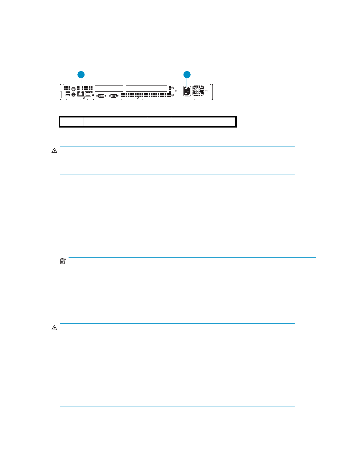
1. Connect a standard Ethernet (CAT-5e or better) cable from your local IP network (LAN) to the
NIC 1 (RJ-45) connector (Figure 10).
10/100/100
0
1 2
10700
1
connector (RJ–45) 1
NIC
2
AC power connector
Figure 10 Appliance rear view
WARNIN G!
To reduce the risk of electric shock, fire, or damage to the equipment, do not plug telephone
or
telecommunications connectors into RJ-45 (NIC) connectors .
For best results, HP strongly recommends that you use a dedicated GbE network to share the storage
resources on the VLS among multiple backup servers.
To ensure optimum performance, always use the appropriate patch cables to connect the VLS to the
backup-server storage network. To select the appropriate cables, use the following guidelines:
• You must use Category 5e (or better) cables for GbE connections.
• If you intend to connect the VLS to a 100 BaseT network, use Category 5 (or better) shielded
(screened) or unshielded 100-ohm twisted-pair RJ-45 network cables.
• The maximum length of cable for any Ethernet-based network connection is 328 feet (100
meters).
NOTE:
For smaller environments, y ou can attach the VLS directly to a single application/backup server
without the user of aswitch. If theserver has aGbit connectionyou candothisusing astandard
Category 5E cable, but if the server has a 10/100Mbit connection then you need a special
LAN cross-over cable (not included).
2. Connect the appliance power supply AC power connector to an AC power source using the power
cable provided (Figure 10).
WARNIN G!
To reduce the risk of electric shock or damage to the equipment:
• Do not disable the power cord grounding plug. The grounding plug is an important
safety feature.
• Plug the power cord into a grounded (earthed) electrical outlet that is easily accessible
at
all times.
• Unplug the power cord from the power supply to disconnect power to the equipment.
• Do not route the power cord where it can be walked on or pinched by items placed
against
the
it. Pay particular attention to the plug, electrical outlet, and the point where
cord extends from the node.
3. Press the power button located on the front of the appliance.
28
Setting up the VLS1000i hardware
Page 29

10986
Figure 11 Push power button
4. If the appliance is racked, attach the bezel to the bezel brackets, installed in "Attach rails to
VLS1000i", then lock the bezel to the server. This will prevent accidental power shut off.
2
1
10987
Figure 12 Attach bezel
Hardware installation is complete. You may now configure theapplianceasdescribed in Configuring the
VLS 1000i.
HP StorageWorks 1000i Virtual Library System
29
Page 30

30
Setting up the VLS1000i hardware
Page 31

3Configuring the VLS1000i
This section describes how to configure the VLS server. It is comprised of the following topics:
• Reviewing pre-Installation requirements
•Powering up the VLS
•Configuring the VLS
• Creating virtual devices
• Connecting devices (targets) to backup hosts (initiators)
Reviewing pre-installation requirements
Before attempting to operate the VLS with your backup servers, verify that the iSCSI initiator and the
minimum requirements.
browser meet
iSCSI initiators
iSCSI initiators are required to communicate with the iSCSI targets (VLS Devices) on the VLS. Each backup
server that will interface with the VLS must be equipped with a software- or hardware-based initiator. The
VLS supports the Windows 2003 platform server with an available iSCSI initiator, either in software or
using an iSCSI HBA (it must be iSCSI draft 20/version 1.0).
the
Browser
The VLS GUI is a Web-enabled program that requires the use of cookies, Java applets, and Java scripts.
Make sure that the Web browser you use is configured to allow these items.
Verifying the settings in Internet Explorer
1. Launch Microsoft Internet Explorer.
2. In the Tools menu, click Internet Options.
3. On the Security tab, click Custom Level.
HP StorageWorks 1000i Virtual Library System
31
Page 32

Figure 13 Custom level on Security tab
4. In the Scripting section, verify that Enable is selected for Scripting of Java applets.
Figure 14 Security Settings
5. On the Privacy tab, verify that the setting is Medium (or lower).
32
Configuring the VLS1000i
Page 33

Figure 15 Privacy setting
6. If you made any changes, click OK to save them.
Verifying the settings in Firefox
Firefox.
1. Launch M
2. In the Tools menu, click Options.
3. Click the Privacy icon, and expand the Cookies option.
4. Select
ozilla
Allow sites to set cookies check box.
the
HP StorageWorks 1000i Virtual Library System
33
Page 34

Figure 16 Allow cookies
NOTE:
If you want to limit what sites can set cookies, use the Exception feature to specify that
ttp://www.hp.com is allowed to create cookies.
h
5. Click the Web Features icon.
6. Verify that the Enable Java and Enable JavaScript check boxes are selected.
34
Configuring the VLS1000i
Page 35

Figure 17 Web features settings
7. If you made any changes, click OK to save them.
Powering on the VLS
To power up the VLS appliance:
1. Plug the node AC power cord into a power source if not already connected.
2. Press the Power button (see Figure 18).
Thefan will initiallybeloud, but willbecomequieter.
3. Wait for the system to beep twice. This indicates the appliance is online.
10986
Figure 18 Press power button
Configuring the VLS
The images shown in the following sections were captured on a Windows system using the Internet
Explorer browser. The screens might appear slightly different if you are using a d ifferent browser or
aUNIX-
based system.
HP StorageWorks 1000i Virtual Library System
35
Page 36

Recording the network configuration
As you complete the configuration process by following the steps, use the following form to note the
information you enter.
IMPORTANT:
will be useful if you have to re-configure the VLS for any reason.
This informati
Table 2 Network configura tion
on
NIC Port 1
IP address: SMTPserverIPaddress:
Subnet mask: From address:
Default gateway: Address for all:
E-mail notification
Address for critical:
Configuring the VLS appliance with the VLS Discovery tool
Use the VLS discovery utility to set the network settings on an unconfigured VLS, and to view the network
settings of configureddevices. The VLSdiscovery utilitylooks forall thedevices on thesamesubnetas
the
Windows computer on which it is running. It then lists the devices and indicates whether they are
configured (have an IP address) or are unconfigured.
To set the network settings using the VLS discovery utility:
1. Insert the VLS Documentation CD into the CD drive on a Windows system that is on the same
subnet as the VLS.
The CD auto-launches.
2. Click VLS discovery utility.
The Scanning for Devices window displays (see Figure 19).
Figure 19 Scanning for devices
The VLS discovery utility opens and lists all the devices it sees on the subnet (Figure 20).
The Configured box for a device is checked if the device has an IP address.
The d evice type, host name, IP address (if available), and serial number are displayed for each
device listed.
36
Configuring the VLS1000i
Page 37

Figure 20 V
LS discovery utility – main window
3. Select the VLS from the list of devices and click Configure.
TheDeviceConfiguration window opens (Figure 21).
Figure 21 VLS discovery utility – Device Configuration window
4. Leavethe default device nameorenter anew oneinthe Device Name box.
5. Enter an IP address in the IP Address box.
6. Enter the subnet mask in the Subn et Mask box.
NOTE:
To display the correct subnet mask, gateway, DNS server, and domain name settings for
the
VLS, open a DOS window on the computer running the VLS discovery utility and
type ipconfig /all.
HP StorageWorks 1000i Virtual Library System
37
Page 38

7. Enter the gateway in the Gateway box.
8. The DNS IP Address and Domain Name are not used. Leave the defaults (if any).
9. Click Configure to save the network settings to the VLS.
10. The Updating Configuration window displays (see Figure 22). Wait for it to close.
Figure 22 Updating configuration
11 . Click Exit to close the VLS discovery utility. The Releasing Devices window displays (see Figure 2 3).
Figure 23 Releasing devices
Configuri
If you can
connect
do this using a standard Category 5E cable, but if the server has a 10/100Mbit connection then you
need a special LAN cross-over cable (not included). From the directly-connected PC you can then launch
the
• You may need to configure the PC networking to enable it to connect to the device’s 10.0.0.1
• Then pe
ng the
VLS v
address (for example set the PC’s IP address to 10.0.0.2, set its netmask to 255.255.0.0, disable
proxy settings in its web browser).
10.0 .
VLS appliance via the default IP Address
not or do not want to use the VLS discovery tool to configure the appliance, you can directly
PC to the VLS LAN port without the use of a switch. If the server has a Gbit connection you can
a
the device’s default IP address (10.0.0.1).
ia
rform the steps in " Verifying the network configuration" to launch the VLS GUI (at address
0.1) and modify the device network settings via the GUI.
Verifying the network configuration
Initially the VLS Discovery tool must be used, as described in Configuring the VLS appliance with the VLS
Discovery tool, to make the VLS available on your network. However, once the VLS is available on your
network, subsequent changes to its IP a ddress, gateway a ddress, and subnet mask can be made using
the
VLS GUI a s shown in the following procedure.
1. In your Web browser on any PC on the network, enter the applicable IP address to access the
VLS GUI.
2. Enter the following in case-sensitive format:
38
Configuring the VLS1000i
Page 39

User Name: administrator
Password: admin
Figure 24 Log onto the VLS
The VLS GUI appears.
NOTE:
To access the online help system from any of the pages in the GUI, click the Help button
that appears on each of the pages. The ? button, when available, will access Help specific
to the current GUI page.
Figure 25 VLS GUI
3. Click the Configuration tab . Then click Network Configuration.
HP StorageWorks 1000i Virtual Library System
39
Page 40

Figure 26 Select Network Configuration on menu
4. In the D efault Gateway section of the right pane, verify that the existing address is the correct one.
5. In the External Data section, verify that the existing IP address and subnet mask are the correct ones.
NOTE:
Itmaytakeupto5minutestosavetheconfiguration information.
Entering the system configuration
On the Configuration tab, under System Management click System Configuration.
40
Configuring the VLS1000i
Page 41

Figure 27 S
elect System Configura ti on
Configuring system information
1. In the System Information section of the right pane, enter the VLS Name.
If you want to change the name of the VLS, enter up to 16 characters to name the VLS. You can use
letters or a mixture of letters and numbers, and you can also use hyphens (-). Ensure that this name
matches the DNS name for the network. HP recommends that you change this name (the default is
VLS-1000), especially if you use multiple VLS appliances in your network.
Figure 28 System Information settings
2. Click A
3. Continue the configuration process by entering the logon information described in the next section.
pply.
Configuring logon information
Using the Logon Information section, you can change your logon name and p assword, which HP Storage
recommends that you do during the initial con figuration process. If you choose to keep administrator
as
your logon name, HP Storage strongly recommends that you change the password to protect your
network from unauthorized users.
1. In the right pane, scroll down below the System Information section to locate the Logon Information
section, and enter the following in case-sensitive format:
• User Nam e (required) Enter a new logon name using up to 30 alphanumeric characters. You
can
use a combination of alphabetic and numeric characters, or you can use only alphabetic
characters. Use of all numeric characters is not supported.
• Password (optional) Enter a new password using up to 30 alphanumeric characters (do not
use spaces or Ctrl-key characters).
HP StorageWorks 1000i Virtual Library System
41
Page 42

• Retype Password Enter the password again.
NOTE:
Changing the password is required.
Figure 29 Setting login information
2. Click Apply.
3. Continue the configuration process by entering the E-mail information described in the next section.
Configuring E-mail alerts
The VLS continuously monitors its performance and routinely checks for disk failures. If you are using an
SMTP server you can enable the messaging option, in which an E-mail is sent whenever the Status of a
volume on the Device Summary page becomes anything other than Normal (for example, changes to
Warning).
NOTE:
Messages regarding capacity levels (Warning and Error) are only sent once.
If your mail server is able to send E-mail messages outside the company, you can also set up messaging
to
notify HP Storage Technical Suppor t automatically whenever a critical error occurs.
To configure messaging
1. In the right pane, scroll down below the Logon Information section to locate the E-mail Notification
section, and enter the following:
• SMTP Server IP Address Using dotted decimal notation, enter the IP address of your incoming
mail
• From Address Enter the E-mail address from which the alert will be sent. This address must
use the same domain as the mail ser ver specified for SMTP Server IP Address.
• Address
exampl
group of backup administrators).
• Address for critical messages only Enter the E-mail address to which critical alerts only
should
ver.
ser
for all messages Enter the E-mail address to which all alerts should be sent (for
e, the E-mail address for the network administrator or the E-mail list address for a
be
sent.
42
Configuring the VLS1000i
Page 43

Figure 30 E-mail Notification settings
2. To verify that the messaging syste
If the test E-mail message is not su
and repeat the test.
NOTE:
If thetestisunsuccessful, makesurethat you are using avalid SMTP Server IP Address
and that the address is working properly.
3. Click Apply.
Setting the time and date information
The VLS is originally set to its time of manufacture. Update the time and date settings to ensure that any
communication (for example, if an E-mail is automatically generated) reflects the correct date and time.
1. In the right pane, scroll down below the E-mail Notification sectionto locatethe SetTimesection.
2. Select the applicable settings, and click Apply.
misconfigured correctly, click Test.
ccessfully sent and received, correct the applicable information,
Figure 31 Set time and date
After you complete these configuration steps for the management system, complete the steps outlined in
the
next section, Deploying iSCSI initiators.
Deploying iSCSI initiators
iSCSI initiators are required to communicate with the iSCSI targets (VLS devices) on the VLS. Each client
that
uses the VLS must be equipped with a software initiator, such as the Microsoft iSCSI Software Initiator,
or an
iSCSI storage HBA (for example, the QLA4050C and QLA4052C).
If you are using Backup Exec software version 10.x or older, you will need an iSCSI card in order to
use the appliance; otherwise, a software iSCSI initiator will work.
If you are using iSCSI HBAs, install them and the associated software using the manufacturer’s instructions.
HP StorageWorks 1000i Virtual Library System
43
Page 44

If youare usingsoftwaredrivers, usefollowing proceduretoinstall Microsoft’siSCSI Software Initiator.
NOTE:
You do not need TOE-equipped (Transmission Control Protocol [TCP] Offload Engine) or special
iSCSI-capable GbE HBAs to work with software initiators. Any standard Network Interface Card (NIC)
can serve as an iSCSI network interface device; however, HP Storage strongly recommends that you
use G bE for enhanced performance.
1. Download the appropriate iSCSI initiator file for your platform from this URL:
ttp://www.microsoft.com/downloads/details.aspx?FamilyID=12cb3c1a-15d6-4585-b385-
h
befd1319f825&DisplayLang=en The file name will likely end in x86fre.exe.
2. Double-click the initiator file to start installing the Microsoft iSCSI Initiator.
3. In the Software Update Installation Wizard, click Next.
4. Under Installation Options, select both Initiator Service and Software Initiator. Click Next.
5. In the License Agreement window please read the agreement, then select IAgree.Click Next.The
installation proceeds.
6. When the installation finishes, click Finish.
7. If necessary, reboot the system.
8. After the system reboots, select Start > All Programs > Microsoft iSCSI Initiator > Microsoft iSCSI
Initiator.
9. In the iSCSI Initiator Properties window, select the Discovery tab.
At this
time, no items are listed under Target Portals.
10. In the T arget Portals section, click Add.
11 . In the Add Target Portal window, enter the I P address of your VLS. Maintain the default port setting.
Click OK.
44
Configuring the VLS1000i
Page 45

Figure 32 iSCSI initiator properties
12. Click OK.
The Microsoft iSCSI Initiator is now installed and configured to work with your VLS on this client. Repeat
this
procedure on each client that will access the VLS.
Obtaining iSCSI address from host
Each device created is associated with one backup host. In order to use the VLS, backup hosts must be set
up
NOTE:
The following process presents associating devices and backup hosts using the Microsoft iSCSI Software
Initiator. The steps and screens may be different depending on the iSCSI solution on your system.
The following steps show how to associate devices with backup hosts.
1. On the host you want to associate with the device being created, select Start > Microsoft iSCSI
2. The iSCSI Initiator Properties window displays. On the General tab is listed the Initiator Node
SI initiators. See Deploying iSCSI initiators for instructions on deploying iSCSI initiators.
as iSC
Initiator > Microsoft iSCSI Initiator.
Name. See Figure 33.
HP StorageWorks 1000i Virtual Library System
45
Page 46

Figure 33 iSCSI Initiator Properties
3. Copy the entire Initiator Node Name. Do not modify the name.
NOTE:
copy the entire Initiator N ode Name. If part of the name is missing, the device will not
Be sure t
be
o
recognized.
Close the iSCSI Initiator Settings window by clicking its OK button.
4. In the Create Virtual Device pane of the GUI, scroll down until you see Host Set tings (Figure 34), then
paste the Initiator Node N ame into the iSCSI Name box in Host Settings as shown in Figure 35.
Figure 34 Host Settings
46
Configuring the VLS1000i
Page 47

Figure 35 iSCSI Name
5. If you want to use an additiona
address of the host system in the iSCSI IP Enforcement field. This is optional.
6. Continue with Creating virtual devices.
Creating virtual devices
TheVLS1000ihas capacityfor thefollowing numbersofdevices:
• 12 virtual tape drives (total of standalone drives and drives in virtual tape libraries)
• 6 virtual tape libraries
• 180 virtual cartridges total (up to 80 cartridges for each virtual tape library)
To select thetypeofdeviceto create, perform the following steps:
1. Open the VLS GUI. See Opening a VLS GUI session from a web browser.
2. In the GUI, select Configuration > Create Virtual Device.See Figure 36.
NOTE:
The Configuration screen defaults to the Backup Host Summary page and begins with no
devices listed. You must use Create Virtual Dev ice.
level of authentication, use dotted decimal notation to enter the IP
l
Figure 36 Select type of device to create
3. Select thetypeof device to create byclicking either Virtual Library or VirtualStandaloneTapeDevice.
4. Continue with the next appropriate section—either Creating a standalone tape device or Creating
a tape library.
Creating a standalone tape device
Perform the following steps to finish creating a tape device:
1. Scroll down, if needed, in the Create Virtual Device pane until you see Device Details (Figure 37).
HP StorageWorks 1000i Virtual Library System
47
Page 48

Figure 37 Creating a tape device
2. If you want to m a ximize backup storage capacity, select the Tape Compression box. For optimal
backup performance, leave this box unchecked.
3. Enter the maximum size of the virtual media in Max Cartridge Size. The default size is the
approximate physical capacity of the device type (for example the physical LTO2 media has physical
capacity of 200 GB).
NOTE:
The Max Cartridge Size is the maximum size the tape is allowed to grow to. Starting with 1
GB
of used space when first created, tapes grow to the maximum permitted as needed. Set
the maximum size to the physical capacity in order to grow to full capacity.
4. Select the appropriate Device Type. (There may be only one type available.)
5. Click Create to create the tape device.
NOTE:
After the tape device is created, the View/Edit Virtual Library or View/Edit Virtual
Standalone Tape screen will display. To create another device at this time, select Create
Virtual Device.
with Creating a tape library.
ue
Contin
Creating a tape library
Perform the following steps to finish creating a tape library:
1. Scroll down, if needed, in the Create Virtual Device pane until you see Device Details (Figure 38).
48
Configuring the VLS1000i
Page 49

Figure 38 Creating a tape library
2. If you want to maximize backup storage capacity, select the Tape Compression box. For optimal
backup performance, leave this box unchecked.
3. Enter the maximum size of the virtual media in Max Cartridge Size. The defaultsizeisthe capacity
of physical LTO2 media, specifically 200 GB.
NOTE:
The Max CartridgeSizeisthe maximum sizethe tape is allowedtogrow to. Starting with 1
GB
of used space when first created, tapes grow to the maximum permitted as needed. Set
the
maximum size to the physical capacity in order to grow to full capacity.
4. Enter the number of tape drives desired in the tape library in Drive Count. The default is 1 drive; the
maximum is 4 drives.
5. Enter the number of virtual tape cartridges desired in the tape library in Cartridge Count.The default
is 8
cartridges; the maximum is 80 cartridges.
NOTE:
To maximize compatibility with the 1/8 Autoloader, leave the default settings of 1 drive
and 8 tapes.
6. Selecting Bar Code Seed tells the VLS to specify the first bar code label and to automatically g enerate
quent labels. Deselecting Bar Code Seed allows you to use your own naming convention. Type
subse
the
name (up to six alphanumeric characters) in the text box that appears.
The sequencing of the bar codes begins with the last character listed before the L2. For example, if
you entered a seed of AAAAAA, the next code is AAAAAB. When the code reaches AAAAAZ,
second to the last characters, and starts over (AAAABA, AAAABB, and so on). If you
ls the
it
rol
e n t e r e d a s e e d o f 111111, t h e n e x t n u m b e r w o u l d a u t o m a t i c a l l y b e 111112 .
NOTE:
If thereismorethan1 VLS1000i on thesamesubnet, HP strongly recommends settingthe barcode seed
manually for each appliance to avoid bar code conflicts.
7. Click on Create to create the drive .
HP StorageWorks 1000i Virtual Library System
49
Page 50

NOTE:
After the drive is created, the View/Edit Virtual Library or View/Edit Virtual Standalone
Tape screen will display. To create another device at this time, select Create Virtual Device.
Continue with Connecting devices (targets) to backup hosts (initiators).
Connecting devices (targets) to backup hosts (initiators)
By this point you have created devices and each device knows which host uses it. Now we need to tell
each host which devices are available to it. Perform the following steps to associate devices to hosts.
NOTE:
The following process presents associating devices and backup hosts using the Microsoft iSCSI Software
Initiator. The steps and screens may be different depending on the iSCSI solution on your system.
1. On the host you want to associate with the device being created, select Start > Microsoft iSCSI
Initiator > Microsoft iSCSI Initiator .
2. On the iSCSI Initiator Properties window, click the Targets tab. As shown in Figure 39 a list of targets
associated with the host you are working on displays.
NOTE:
Initially, there are no targets to display. Targets will display as you create them.
Figure 39 Ready to find targets
3. In order to associate any n ew devices with this host, click Refresh.The LAN will be queried for all
devices set up for use by this host and all targets found will display (Figure 40). In this manner you
can
both add newly created devices and remove from the list any d evices that have either been
deleted or have had their host association changed to another host.
50
Configuring the VLS1000i
Page 51

Figure 40 Targets found
4. The final step is to make the devices known to the host’s operating system. This is done by clicking
in the iSCSI Initiator Properties window (Figure 40), then clicking on Log On.
devic
e
Target window displays (Figure 4 1). If you want a persistent device (one that survives
to
on a
5. The Log On
host reboots), click Automatically restore this connection when the system boots.Click OK.
Figure 41 Log on to target
NOTE:
Enabling multi-path is not recommended unless there is a specificreasonto enableit. For
most configurations, it is neither necessary nor desirable.
6. The device will now be seen by the operating system which will at tempt to load the necessary
device drivers. (If drivers are not necessary, they need not be loaded.) If the drivers do not already
exist on the host, you can download the HP LTO Ultrium-2 tape drivers from the HP web site
ttp://www.hp.com). Complete the logon procedure for each device listed.
(h
The backup devices are now available for use with a backup program.
HP StorageWorks 1000i Virtual Library System
51
Page 52

52
Configuring the VLS1000i
Page 53

4 Working with the VL S1000i
This chapter provides a few tips on working with the VLS including:
• Logging on from any system with net work access
• Understanding the summary pages
• Understanding how dynamic tape devices work
• Checking communication with other appliances or systems
• Rebooting the VLS
• P owering down the VLS
Logging on fr
After you hav
subnet as the VLS.
Be aware of the following:
• If you log on
logs you off
• After an hour of inactivity, the VLS GUI automatically logs you off the system.
To
log on from any system:
1. In your Web browser, type the IP address assigned to the VLS.
2. When the prompt appears, type your user name and password (the defaults are administrator
and
admin
om
econfigured the VLS, you can access the VLS GUI from any system that is on the same
any system with network access
from one system and then log on from another system, the VLS GUI automatically
from the first system.
)incase-sensitive format.
Figure 42 VLS GUI login window
The VLS GUI appears.
HP StorageWorks 1000i Virtual Library System
53
Page 54

Figure 43 VLS GUI Identity page
Understanding the Configuration page
The VLS software includes a configuration page with several options that allow you to configure hosts and
VLS devices, and view summ a ries of the devices that already exist.
NOTE:
Thesizeof a device reflects the space that is available on a disk; one GB equals one billion bytes. (The
calculation of 1000 ° 10 00 ° 100 0 in s tead of 1024 ° 1024 °1024.)
VLS uses
Reviewing the Backup Host Summary page
The Backup Host Summary page provides an immediate view of your VLS and its status. The following
shows an example of what you might see on this page (what you see depends on how you configure
your appliance).
the
54
Working with the VLS1000i
Page 55

Figure 44 B
The follow
• Host Name The iSCSI name of the Initiator associated with the following table of VLS devices.
• Device Name Displays either the default name assigned by the VLS or the new name assigned
by
you.
• Device ID This entry is automatically designated by the VLS.
• Device Status Indicates whether the device is operating normally or not. The status indicators
are expl
• Device Type Indicates whether the device is exported as a standalone drive, a library, or as
a
library tape drive.
• Size (GB
ackup Host Summary page
explains ea ch of the fields:
ing
ained in Table 3.
Indicates the amount of space allocated to the device.
)
Understanding the View/Edit Virtual Library page
The Library Summary page displays high-level information about your virtual libraries (VLs) and p rovides
access to all pages associated with a VL. Before you create a VL, only the upper sections of the page
(Capacity Summary and Resources) are displayed. After you create a VL, the Current VLS Summary
section is added.
HP StorageWorks 1000i Virtual Library System
55
Page 56

Figure 45 View/Edit Virtual Library page
IMPORTANT:
Make sure there are no currently active hosts (initiators) accessing the VL when changing settings.
The following explains each of the items:
• Available Space Indicates the amount of space that remains on the appliance.
• Used Capacity Indicates how much space on the appliance is currently consumed by the data
stored in the appliance’s virtual devices.
• Available VLSs Indicates the number of VLs that you can create (as you create a VL, this number
decreases accordingly).
• Available Vir tual Cartridges Indicates the number of virtual tapes that are currently available
for use by new VLs.
• Available Virtual Drives Indicates the number of virtual tape drives that are currently available for
use by new standalone drives and VLs.
• VLS # Indicates the number automatically assigned by the VLS GUI.
• Name Indicates the D escriptive Name automatically assigned by the GUI.
• Library Configuration Accesses the Modify Target Configuration page where you can change
settings such as compression, drive count, cartridge count, and the names of targets.
• Host Configuration Accesses theEditHost Configuration page where you can change the host
associated with the VL and add IP enforcement.
• Display Accesses the VLS Status page, which displays a device summary and a cartridge map.
• Drives Lists the number of virtual tape drives assigned to the VL.
• Cartridges Lists the number of virtual tapes assigned to the VL.
• Library To remove a VL, click Delete the VL.
• Unload Drives Click Unload Drives to mark a drive as empty. This is used in case of a power
interruption when ba ckup applications were running. Unload Drives unloads all of the drives in
the VLS1000i.
56
Working with the VLS1000i
Page 57

Logging off of the VLS GUI
To logoff theVLS GUI, closethe browserwindow.
NOTE:
The V LS GUI will time-out if unused for one hour.
Understanding how dynamic tape devices work
As explained previously, Dynamic Tape devices contract and expand to accommodate the size of
aspecific backup job.
When your backup software starts a job, it mounts the Dynamic Tape device as if it were a physical
tape, and then begins the backup process by launching a Write operation. During this process, if the
tape position in the backup software corresponds to a logical-block address (LBA) that is less than 3, the
software treats the device as though it were overwriting a tape, and the VLS reduces the capacity of the
device to 1 GB. The appliance then releases the unused storage back into a virtual storage-pool (VSP).
When the backup software reaches an early warning (EW) state (EW is reached when less than
100 MB of space remains on the current device), the VLS reviews the following to determine whether
it
can expand the size of the device:
1. It determines how much space is already consumed.
• If the current consumption exceeds 70 percent of the VSP, the appliance sends a “warning”
message to the E-mail address specified for alerts.
• If the current consumption exceeds 90 percent of the VSP, the appliance sends a “critical”
message to the E-mail address specified for alerts.
2. It determines whether you specified a maximum size for the device.
•If a maximum size is specified (either by using the default value of 200 GB or setting a
different value), the appliance determines whether expanding the size of the tape by 1 GB
would exceed the specified capacity.
• If the expansion would not exceed the limit, the appliance increases the size of the tape by
1
GB. If the expansion is successful, an EW is not reported to the backup software. If the
expansion is unsuccessful, the EW is relayed to the backup software.
• If the expansion would exceed the limit, an EW is relayed to the backup software.
•If you specified the full capacity of the VSP, the appliance attempts to expand the size of the
tape in 1 GB increments until the full capacity is reached. The tape full VSP tape size can
only be reached if the size is set to the full VSP.
Checking communication with other appliances or systems
The Maintenance page includes a section that lets you check network connectivity with any system,
appliance, passthrough device, or other device that has an IP address. The VLS GUI uses a ping
command
1. On the Support tab under Maintenance, click Ping Host. In the Ping Host IP Address pane (see Figure
to perform this check.
46), type the IP address of the system that you want to check, and click Ping.
HP StorageWorks 1000i Virtual Library System
57
Page 58

Figure 46 Ping page
2. The VLS GUI displays a message (see Figure 47) that indicates whether the ping command
succeeded
Figure 47 Ping results messages
or failed.
Refreshing the VLS GUI display
The VLS GUI does not refresh the display automatically.
To view updated information, click the applicable menu command to refresh the page.
IMPORT
Do
58
ANT:
the Refresh button in your browser to update a page. If you do, you will be logged off.
se
not
u
Working with the VLS1000i
Page 59

Relocating an a
IMPORTANT:
To ensure preservation of data on the VLS, do not turn off the appliance using the power button; instead,
usethe Shut Down option in theVLS GUI.
NOTE:
The following process presents associating devices and backup hosts using the Microsoft iSCSI Software
Initiator. The steps and screens may be different depending on the iSCSI solution on your system.
To shut down, move, then restore power to an appliance:
1. Make sure that none of the initiators (hosts) have active connections with the VLS.
For example, in the iSCSI Initiator Properties dialog box for the Microsoft initiator, you can check the
Targets tab to determine if there are any connections that may need to be terminated.
ppliance
Figure 4
2. If any o
an
acti
is
connected and then click Details.
Connected targets
8
the targets in Figure 48 have the status Connected, there is a possibility that there is
f
session. To find out if there are any active sessions, click on one of the targets that
ve
HP StorageWorks 1000i Virtual Library System
59
Page 60

Figure 49 Log off sessions
3. Click the box under Identifier, as shown in Figure 49.Click Log off.The system will attempt to log off
the
current target’s session. If there is currently activity on this session, you will get a message saying
“The session cannot be logged out since a device on that session is currently being used.” If you
receive this message, either wait until the activity finishes or cancel the activity. Repeat steps and
Step 3 to log off all connected targets.
4. On the Support tab under M aintenance, click Shut Down/Restart.On the Shut Down/Restart
page
(see Figure 50), click Shut Down.
Figure 50 Shut Down/Restart page
5. When the confirmation message appears, click OK to continue.
60
Working with the VLS1000i
Page 61

Figure 51 Shut down confirmation
6. Wait until the fans stop (this m ay take several minutes), then disconnect the AC line cord from
the
power mains.
7. Unplug all connections, and label them so that you can reattach them using the same connection
configuration.
8. If the appliance is in a rack, remove it by extending the slide rails and then releasing the slide locks.
CAUTION:
Extending a unit that has empty spaces beneath it might cause the rack to tip forwar d
or
might cause personal injury.
9. Move the appliance to the new location.
10. Connect the appliance to the network.
For more information, see Installing cables.
11 . Attach the p ower cord to the appliance and plug the cord in to an AC power source. Press the
power button to start the VLS.
For more information, see Powering up the VLS.
Rebooting the VLS
To reboot the appliance:
1. Verify that any backup or restore operation has completed and that the VLS is idle.
2. Open the VLS GUI. See Opening a VLS GUI session from a web browser.
3. Initiate a reboot of the VLS by selecting the GUI’s Support tab, selecting Shut Down/Restart,and
clicking Restart.See Figure 52.
HP StorageWorks 1000i Virtual Library System
61
Page 62

Figure 52 Shut down and restart the VLS
Powering off the VLS
WARNING!
risk of personal injury, electric shock, or damage to the equipment, remove the power
To reduce t
cord to rem
does not
remain active until AC power is removed.
To power down the appliance:
1. Verify tha t any backup or restore operation has completed and that the VLS is idle.
2. Op en the VLS GUI and log in. See Opening a VLS GUI session from a web browser.
3. Initiate a shut down of the VLS by selecting the GUI’s Support tab, selecting Shut Down/Restart,and
4. Theappliancewillshutdown.
5. Unplug the node AC power cord from the power source if you will be removing the access panel.
he
power from the node before removing the access panel. The front panel Power button
ove
ompletely shut off system power. Portions of the power supply and some internal circuitry
c
clicking Shut Down.See Figure 52.
The appliance is now without power.
62
Working with the VLS1000i
Page 63

5 VLS1000i G UI
The VLS1000i GUI is a web browser–based GUI that you can use to configure, manage, and monitor
your VLS through a LAN. VLS GUI provides the following:
• Configuring and managing VLS virtual devices (libraries and tape drives) and cartridges
• Viewing a summary of backup hosts configured to use the VLS and the virtual devices associated
with each host
• Entering or verifying the VLS network configuration
• Configuring VLS E-mail notification alert settings
• Editing of VLS logon information
• Viewing VLS hardware and virtual device status
• Installing VLS software updates
• Saving and restoring the VLS device configuration
• Shutting down and restarting the VLS
• Generating support tickets
The VLS GUI is installed on the VLS and communicates through the LAN. Users can open a VLS GUI
session from a web browser on the LAN.
Window regions
VLS GUI windows c onsist of five regions (Figure 53). Not all regions are displayed on all windows.
HP StorageWorks 1000i Virtual Library System
63
Page 64

1
System status indicator
2
GUI tabs
3
Navigation pane
Operation pane
4
5
Context-sensitive help (CSH)
button
6
Help system button
Figure 53 GUI windo w regions
Opening a VLS GUI session from a web browser
NOTE:
Before you can open a VLS GUI session, you must set the VLS network settings. See Configuring the VLS
appliance with the VLS Discovery tool.
To open a VLS GUI session from a web browser:
1. Launch a web browser.
2. In the web browser U RL box, enter the VLS I P address.
64
VLS1000i GUI
Page 65

Figure 54 VLS GUI login window
3. Enter administrator (or the user name you set) in the User Name box (Figure 54). The user
name
is case
4. Enter admin (or the password you set) in the Password box (Figure 54). The password is
case-sensitive.
5. Click Sign
NOTE:
Only one VL
cause the fi
-sensitive.
In.
GUI session at a time is allowed. Starting a second VLS GUI session will
S
rst sessions to log out.
Closing a VLS GUI session
To close a VLS GUI session, simply close the browser window.
NOTE:
The VLS GUI session will logout after one hour of inactivity.
VLS GUI tabs
The following sections describe the VLS GUI tabs.
VLS Identity tab
This page lists information specifictothissystem.
• VLS Name Displays thenamespecified for this system on the System Configuration page.
• VLS Mode
• IP Address Indicates the IP address specified for accessing the appliance on the Network
Configuration page.
• Version Displays the version of the software currently installed on the appliance.
• Avail
• Number of Virtual Libraries Indicates the number of virtual libraries that have been created.
able
Identifies the mo d el number of the appliance.
l
Capacity Indicates the amount of unused space on the appliance.
HP StorageWorks 1000i Virtual Library System
65
Page 66

• Number of Standalone Drives Indicates the number of standalone tape drives that have been
created.
• VLS Serial Number Identifies the serial number of the appliance.
Configuration tab
Create Virtual Device
Use this page to create a virtual library or virtual standalone tape.
Virtual Device Information
Select the applicable option, Virtual Library or Virtual Standalone Tape Device.
NOTE:
The option yo
their defaul
iSCSI Host Settings
• iSCSI Name In the text box, type the iSCSI name of the host system that is allowed to access
this
• iSCSI IP Enforcement (optional) If you want to use an additional level of authentication, use dotted
decimal notation to enter the IP address of the host system in this field.
u
are.
ts
library or device.
select changes which features are displayed on the remainder of this page and what
Device Details
The options that are available in the following list depend on whether you are creating a library or tape.
• Tape Compression If your backup software supports a hardware compression feature for use with
• Max Cartridge Size Enter the maximum size that you want to allow the device to reach. The default
• Device Type Select theapplicabletype. (There maybeonlyone type available.)
• Drive Count Enter the number of virtual tape drives that you want to allocate for the virtual library.
• Cartridge Count Enter the number of virtual cartridges (and corresponding slots) that you want
• Bar Code Seed To let the GUI specify the first bar code lab el and automatically generate
IMPORTANT:
After you submit this page by clicking Create, you can only incr ease the number of cartridges and slots
assigned to the virtual library.
View/
Edit Virtual Library
tape, you can use this option to emulate that feature. For optimal backup performance, leave this
check box cleared; to maximize the backup storage capacity, select this check box.
value is 200 GB. Set the maximum size to the physical capacity in order to grow to full capacity.
to
allocate for the virtual library. The GUI automatically creates a virtual tape-device for each
cartridge.
subsequent labels, leave the Automatic check b ox selected. To enter the first label manually,
clear the check box, and type the name in the text box that app ears (you can enter up to six
alphanumeric characters).
is page
Use th
he
view t
virtual library; or remove a virtual library.
66 VLS1000i GUI
to view the amount of space currently consumed by the data stored in the virtual libraries;
number of existing virtual libraries, cartridges, and drives; modify information for an existing
Page 67

Capacity Summary
• Available Space indicates the amount of space that remains on the appliance.
• Used Capacity indicates how much space on the appliance is currently consumed by the data
stored in the virtual libraries.
Resources
• Available VLSs indicates the number of virtual libraries that you can create (as you create a virtual
library, this number decreases accordingly).
• Available Vi
for use by a vi
• Available Virtual Drives indicates the number of virtual-tape drives tha t are currently available
for use by a virtual library.
Configured VLS Summar y
This section lists high-level information about each existing virtual library, provides access to additional
information, and lets you change the settings for or remove an existing virtual library.
• Library # The system automatically assigns this number, beginning with zero.
• Device ID Indicates the Descriptive Name automatically assigned by the system or manually
entered by you.
• Drives Lists the number of virtual drives assigned to the virtual library.
• Cartridges Lists the number of virtual tapes assigned to the virtual library.
• Library Configuration Accesses the Modify Target Configuration page where you can change
settings s uch as compression, drive counts, and the names of targets.
• Host Confi guration Accesses the EditHostConfiguration page where you can modify the initiator
information for the host, or select a different host.
• DisplayShows the status of the library.
• Library Allows you to delete the library.
• Unload Drives Allows you to unload all the drives on the selected library.
rtual Cartridges indicates the number of virtual tapes that are currently available
rtual library.
Modify Virtual Library Configuration
Usethe pagetoconfirm or change the settings for the virtual library (VL) and its targets.
VLS Settings
• SCSI Vendor ID Displays the ID automatically generated by the appliance. (Your backup software
might require this information.)
• SCSI Product ID Select the ID that you want to associate with the VL. (Your backup software
might require this information.)
• Compression If your backup soft ware supports a hardware compression feature for use with tape,
you can use this option to emulate that feature. For optimal backup performance, leave this
check box cleared; to maximize the backup storage capacity, select this check box. This option
applies to all virtual-tape cartridges on the VL.
• Maximum Capacity p er Tape Enter the maximum size (up to 2000 GB, depending on space
available) that you want to allow each virtual tape to reach.
• Drive Count Enter the number of virtual drives that you want to allocate to the VL. Depending on
the
number of drives remaining, you can enter up to 4.
• Cartridge/Slot Count Enter the number of virtual tapes and corresponding slots that you want to
allocate to the VL. Depending on the number of cartridges remaining, you can enter up to 80.
HP StorageWorks 1000i Virtual Library System
67
Page 68

NOTE:
You can only increase the size or number of drives and slots; you cannot decrease them.
Target Settings
• Device Name Displays the name of the device automatically assigned by the GUI.
• Target Name To change the default target nam e of a device, type the new name in this field. (All
targets must have an iSCSI name.)
• LUN The Logical Unit Number assigned by the appliance to each created device.
• SCSI SN Displays the Small Computer System Interface (SCSI) serial number (SN) automatically
assigned to the device by the GUI.
Edit Host Configuration
Use this page to update information for the selected initiator.
• Connection Type Indicates that the connection type is iSCSI. You cannot modify this setting.
• Host Name If you have existing initiators and want to use one of them, select it from this pick list.
• iSCSI Host Name Enter the new name (you can enter up to 223 alphanumeric characters) for
the
authorized initiator. The fully qualified name is assigned by the manufacturer of either the
software initiator or storage adapter that you are using. The name that you enter here must match
the
name of the initiator on the associated system. To assign an existing host name, highlight the
current host name then select the new initiator name from the pick list.
• iSCSI IP Address If you want to use an additional level of authentication, use dotted decimal
notation to enter the IP address of the initiating system.
Virtual Library Status
Use this page to view a list of the devices, slots, and drives assigned to this virtual library (VL), and
information about each.
Device Summary
• Description Lists the data-transfer elements, such as changers and tape drives, assigned to the VL.
• Device Name Displays thenameofthe target (device).
• Serial Number Displays the SCSI serial number automatically assigned to the target by the GUI.
Cartridge Map
• Element Indicates whether the slot is used as a bin for a virtual tape-cartridge or contains
a
virtual drive.
• Media Type Identifies which type of m edia is emula ted, for example, LTO-2 tape devices.
• Bar Code Label Lists the label assigned to the element based on the labeling scheme used by the
VL or
reports Empty if there is no label assigned.
• Used Capacity Displays how much space (in gigabytes) is currently consumed by the virtual tape.
View/Edit Virtual Standalone Tape
Use this page to view a list of the existing standalone devices, to access the page where you can change
the
attributes of a device (click Modify), or to remove a device (click Delete).
• Device ID Indicates the ID automatically assigned to the d evice by the system or by the user.
• Device Name Indicates the name automatically assigned to the device by the system.
• Device Status Indicates the current state of the device.
• Size (GB) Indicates the amount of space currently being used by the device.
68 VLS1000i GUI
Page 69

NOTE:
The size of a device reflects the space that is currently being used on a device; one GB equals one billion
bytes. (The appliance uses the calculation of 1000 x 1000 x 1000 instead of 1024 x 1024 x 1024.)
• Compression Indicates whether the compression feature was enabled for the device.
Modify Virtual Standalone Tape Configuration
Use this page to modify the compression, maximum s ize, device name, and host name for an existing
virtual Tape Device.
• Device Type Indicates that the device is a Standalone Tape Drive.
• Enable Tape Com pression If your backup software supports a hardware compression feature for
use with tape, you can use this o ption to emulate that feature. For optimal backup performance,
leave this check box cleared; to maximize the backup storage capacity, select this check box.
• Maximum Cartridge Size Enter the maximum size that to allow the device to reach. The default
value is 200 GB. Set the maximum size to the physical capacity in order to grow to full capacity.
NOTE:
If you decide to change the maximum size at a later date, be aware that you can only increase the
size; you cannot reduce it. To use a device with a smaller maximum size, you must either delete this
device and recreate it using the desired size, or create an additional device that uses the desired size.
• iSCSI Device Name To change the default target name of a device, type the new name in this
field. (All targets must have an iSCSI name.)
• Current Cartridge Size Indicates the amount of space currently being used by the device.
• Tape Serial Num ber The serial number assigned by the GUI to this device.
• Status Indicates the current state of the device.
• iSCSI Host Name Use this field to change the name of the host system that accesses this
standalone tape.
• iSCSI Host IP Address If you want to use an additional level of authentication, use dotted decimal
notation to enter the IP address of the host system in this field.
Backup H
ost Summary
Use this
scurrently defined on the appliance. For each host, this page shows information such as which
device
devices (targets) it is associated with.
Hardware Status
Use this page to monitor the status of volumes and each disk. Your can also use this page to verify the
RAID unit (after aRAIDvolumeiscreated,thatis, theStatusisOK, click Verify to make sure that the
unit is
fully functional).
Table 3 Hardware status indicators
Norma
Warning
Error
page to view a summary of the initiators (backup h osts) that are assigned to the libraries and
l
ates that all components within the VLS are
Indic
ting
opera
Indicates that the RAID configuration is operating
in a
operational but not protected.
Indicates that either the RAID configuration or a
specificdiskfailed.
normally.
degraded state or is rebuilding. Devices are
HP StorageWorks 1000i Virtual Library System
69
Page 70

Network Configur
ation
Usethis pageto
Default Gateway
• IP Address Verify that this field contains the correct IP address for the gateway.
External Data
• VLS IP Address Using dotted decimal notation, enter a static IP address that is available for the
port within its respective subnetwork.
• VLS Subnet Mas
segment (for
• VLS MAC Address Indicates the Media Access Control (MAC) number of the port.
System Configuration
Usethis pagetospecify system configuration values for the appliance, change the user name and
password used for access to the GUI, establish automatic E-mail notification of errors, and modify
the appliancedateand time.
System Information
• VLS Name Enter up to 16 characters to name the appliance. You can use letters or a mixture of
letters and numbers, and you can also use hyphens (-). We recommend that you change this
name (the default is VLS-1000), especially if you use multiple appliances in your network.
specify the configuration values for the network port.
Using dotted decimal notation, enter the subnet mask value of the network
k
example, 255.255.255.0).
Logon Information
Use this section to change your user name and password, which we recommend that you do during
the
initial configuration process. (If you choose to keep administrator as your user name, we strongly
recommend that you change the password to protect the appliance from unauthorized access.)
IMPORTANT:
Both the user name and the password are case-sensitive.
• User Name Enter a new user name using up to 30 alphanumeric characters. You can use a
combination of alphabetic and numeric characters, or you can use only alphabetic characters.
NOTE:
Although the GUI allows you to enter and apply a name that uses only numbers, the change is not
saved. When you log on to the GUI using the new name, an error message appears; you must enter
the original name to log on.
• Password Enter a new password using up to 30 alphanumeric characters (do not use spaces or
Ctrl-k
• Retype Password Enter the new password again.
E-mail Notification
The appliance continuously monitors its performance and routinely checks for disk failures. If you use this
feature, an E-mail message is automatically sent to the specified address whenever the Status of a volume
becomes anything other than Up (for example, changes to REBUILDING).
ey characters).
70 VLS1000i GUI
Page 71

• SMTP Server IP Address Using dotted decimal notation, enter the IP address of your incoming
mail server.
• From Address Enter the E-mail address from which the alert will be sent. This address must use the
same domain as the mail server specified forSMTP ServerIPAddress.
• Address for all warnings and c ritical messages Enter the E-mail address to which all aler ts should
be
sent (for example, the E-mail address for the network administrator).
• Address for critical messages only Enter the E-mail address to which only critical alerts should be
sent.
To verify tha t the messaging system is configured correctly, click Test. If the test E-mail message is not
successfully sent and received, correct the applicable information, and repeat the test.
Set Time
The applianc
up
the applia
settings a ccordingly. This ensures that any log files or communications that occur (for example, if an
E-mail is automatically generated) reflect the correct date and time.
Support tab
Software Update
This page displays the following:
• Product Version Displays the version of the software.
• Serial Nu
• Flash Version Displays the version of the embedded operating system.
To access the update page, click Upda te.
is originally set to use the time that corresponds to the Pacific time zone. If you are setting
e
in a different tim e zone, use the options in this section to update the time and date
nce
mber Displays the number assigned to your appliance.
Update System
Using the Browse button, locate the load file with which to update the VLS. Click Submit.
Save/Res
tore Configuration
• Save This feature saves all configuration-related information, such as virtual libraries, devices, and
host-system information, to a location specified by you. (We strongly recommend that you invoke
this feature after you initially set up your system, and whenever you a dd a new library or tape
device o
System
• Restore This feature restores the saved configuration (it recreates the virtual libraries, devices,
and
IMPORTANT:
Invoking the Restore feature deletes all existing backup data from the appliance regardless of the status of
the restore command. (If the command does not complete successfully, all devices will still have been
ed and
delet
Support Ticket
Use the Generate Support Ticket page when you are instructed to do so by Technical Support. The
Technical Support representative will guide you through the applicable log to find the necessary
information. Select the check box for the log file that you want to create, then click Save to store the file
on your system for subsequent viewing and research. (The file extension should be “.tgz”.)
change configuration settings.) After you save the configuration, the system adds a
r
Configuration log to the Generate Support Ticket page.
host-system information).
all data lost.) That is, it only restores the configuration; it does not restore backup data.
HP StorageWorks 1000i Virtual Library System
71
Page 72

NOTE:
Use a text editor to view the file after you have saved it. We recommend that you use WordPad on a
Windows system, because it displays the configuration informationinaneasy-to-use format.
Ping Host
Use the Ping Host IP Address page to check network connectivity between the appliance and a host
system. Enter the IP address, and then click Ping. The GUI displays a message that indicates whether the
ping succeeded. After reviewing the m essage, click Continue to proceed.
Shut Down/Restart
Before using either of these options, make sure that none of the initiators (application and backup
systems) are currently accessing the appliance (that is, make sure that an initiator is not using the
appliance to perform a backup).
• Restart To shut down the appliance briefly and then automatically restart it, click this button. Wait
several minutes before you log back on to the GUI.
• Shut Down To shut down the appliance and leave the power off, click this button. Wait several
minutes before you perform any maintenance on the appliance.
VLS1000i Help
Selecting VLS1000i Help opens the entire help system.
Support Links
Where can I find more information?
The following H P StorageWorks 1000 Virtual Library System (VLS) documents are available online on
the
HP web site (h
with the VLS.
HP StorageWorks 1000i Virtual Library System user guide
This ma nual describes the VLS features, models, components, installation, operation, user interface, and
typical configuration and administration tasks. It also describes how to view hardware status and alerts,
replace customer-replaceable components, per form disaster recovery, and troubleshoot the VLS.
HP Support URL
You can view and download the latest release notes, troubleshooting information, software versions,
documentation, help files, andsoonfromthe HP website (h
ttp://www.hp.com) and some are also available on the documentation CD shipped
ttp://www.hp.com).
72 VLS1000i GUI
Page 73

6 Maintenance
As you perform maintenance on the VLS, keep the following guidelines in mind:
• Do not turn off the VLS using the power button on the appliance. Verify that none of the initiators
have active connections, and use the Shutdown/Restart option in the GUI to shut down the VLS.
• If a peripheral does not work, make sure that all connections are secure.
Operational m
As long as the VLS1000i is operational, there are many tools to help you diagnose issues and correct
them:
• To appraise
List of e-ma
• Log files are automatically created to help you diagnose issues (see Log and configuration files).
• The VLS configuration can b e saved to a file to make future configuration recovery possible (see
Log and configuration files).
• Single dri
List of E-mail alerts
As explained earlier in Configuring e-mail alerts, the VLS continuously monitors its performance and
routinely checks for disk failures. If the messaging option is enabled, an E-mail is sent whenever the status
of a volume on the Hardware Status page changes.
Each message includes the serial number for the appliance.
NOTE:
Messages regarding capacity levels (Warning and Critical) are only sent once.
Table 4 lists sample messages.
ve failures can be found and repaired (see Single drive failure).
aintenance
you of appliance status, the VLS1000i can be confi gured to send E-mail alerts (see
alerts).
il
HP StorageWorks 1000i Virtual Library System
73
Page 74

Table 4 E -mail messages
E-mail sub
All Units OK <blank> A previous alert state has been cleared.
Device Event, Unit SN:
<TapeSerialNumber>
Device
<TapeS
Device Event, Unit SN:
<TapeSerialNumber>
E-mail Test, SN:
<VLSserialNumber>
Device Event, SN:
<VLSserialNumber>
ject
Event, Unit SN:
erialNumber>
E-mail bod
Remaining Capacity Level:
Warning <percentage>
Remaining Capacity Level:
Critical <percentage>
Remaining Capacity Level:
Safe
This is a test E-mai l.
VLS Name: <VL-
Sname>HOST: 1 HOT SPARE
OKRAID5:PU:01 INITIALIZING
(0%)RAID5:PU:02 INITIALIZING
OKRAID5:PU:13 INITIALIZING
(0%)RAID5:PU:14 INITIALIZING
(0%)
y
(0%)HOST: 2 HOT SPARE
Indicates
A standalone Dynamic Tape device exceeded 70
percent of its Dynamic Tape Maximum Size setting. If
the total available capacity for the appliance is less than
the maximum-size limit for the device, the 70 percent
threshold is calculated against the available capacity
instead of the maximum-size limit.
A standalone Dynamic Tape device exceeded 90
percent of its Dynamic Tape Maximum Size setting, the
um
maxim
the ap
devi
the available capacity instead of the maximum-size limit.
An overwrite operation reset the standalone Dynamic
Tape device to its default starting capacity of 1 GB.
The test E-mail was successful, and the alert function is
configured correctly.
Ind
gical volumes) configuration and identifies the status
lo
of each physical unit (PU).
is 1.5 TB). If the total available capacity for
pliance is less than the maximum-size limit for the
ce, the 90 percent threshold is calculated against
icates that you selected a RAID 5 (with or without
Log files
Storage Pool Event, Unit
SN: <VLSserialNumber>
Storage Pool Event, Unit
SN: <VLSserialNumber>
Storage Pool Event, Unit
SN: <VLSserialNumber>
Server Name: <VLSname>
Warning-Level Alert: Percent
Used: <percentage> Total
Capacity (GB): <capacity>
Available Capacity (GB):
<capacity>
Server Name: <VLSname>
Critical-Level Alert: Percent
Used: <percentage> Total
Capacity (GB): <capacity>
Available Capacity (GB):
<capacity>
Server Name: <VLSname>
Safe-Level Alert: Percent Used:
<percentage> Total Capacity
(GB): <capacity> Available
Capacity (GB): <capacity>
Indicates that the amount of space allocated for use by
devices of type Disk and Tape exceeds 70 percent of
the total space available on the appliance.
Indicates that the amount of space allocated for use by
devicesoftypeDiskand Tape exceeds90percent of
the total space available on the appliance.
Theamountofspace allocatedfor usebydevices of
type Disk and Tape is now less than 70 percent of the
total space available on the appliance.
The VLS creates and maintains log files that contain diagnostic information intended for use by HP
Storage Technical Support in troubleshooting issues you might encounter. The logs are updated every 60
seconds, with new information appended to the beginning of the applicable file. When the maximum
log-file size is reached, previous information is deleted so that new information can be added.
To retrieve the log files
1. On the Support tab under Maintenance, click Support Ticket. The Generate Support Ticket pane
displays as shown in Figure 55.
74 Mainte n ance
Page 75

Figure 55 Select log files
2. In the Generate Support Ticket pane, select the log files you want to view. Click Save to create an
archive file containing the selected log files.
3. Verify that the extension on the archive file is “.tgz”.
4. Review the contents of the log files contained in the archive file.
Configuration files
On request, the GUI creates a file of the VLS’s configuration.
To
create the VLS configuration file:
1. On the GUI’s Support tab under Maintenance, click Save/Restore Configuration.
2. In the Save/Restore VLS Device Configuration section, click Save.
Figure 56 Save configuration file
3. When the created message appears, click Continue to download the file.
HP StorageWorks 1000i Virtual Library System
75
Page 76

Figure 57 Created file message window
4. When the File Download window displays, click Save. In the Save As window that displays, navigate
to where you want to save the file. Click Save.
Figure 58 Download configuration file
5. If the configuration file already exists, a window displays asking if you want to replace it. You can
either click Yes and replace it, or click No. This returns you to the Save As window where you can
replacing the existing one.
change thenameofthe configuration file andthensaveitwith
out
Figure 59 Save the configuration file
6. When the download finishes, the Download Complete window displays. Click Close.
Single drive failure
If only one drive fails, the VLS1000i continues to function; when more than one d
can
not continue. Therefore, if a drive fails it is important to repair it before another drive fails. The
following notifications are provided when a drive fails:
• An E-mail alert will be sent (if the VLS1000i is configuredtosendthem).
• The Hardware Status page will display an error icon on the failed drive.
To repair the failed drive:
1. Insert the Diagnostic/Quick Restore CD in the CD-ROM drive.
2. Power off the appliance (see Powering down the VLS)but select Restart. Do not unplug the
node AC power cord.
76
Maintenance
rive fails, the VLS1000i
Page 77

3. Push thepower button to boot theappliancefrom the Diagnostic/Quick RestoreCD. The
CD
checks the appliance and visually displays which drive has failed (see Using the
Diagnostic/Quick Restore CD).
4. Remove the Diagnostic/Quick Restore CD from the CD-ROM drive
5. Push the power button to turn off the appliance and unplug the node AC power cord.
6. Replace the failed drive (see Hard disk drives).
7. Plug in the nod e AC power cord and push the power button to start the appliance.
The disk array will automatically rebuild without data loss. A warning icon displays in the Hardware
Status page until the rebuild is complete. Performance will be reduces during the rebuild.
Non-operational diagnostics and recovery
In some cases, a failure will render the VLS1000i non-operational. These failures include:
•Multiple dr
• Firmware corruption
•Fatal hardware failure
• Appliance
Multiple drive failure
If multiple drives failed, it is b ecause the RAID has failed. All data (including firmware, the configuration,
data on the virtual tape) is lost. To repair the device and return it to operational status:
1. Insert the Diagnostic/Quick Restore CD in the CD-ROM drive.
2. Power off the appliance (see Powering down the VLS)but select Restart. Do not unplug the
node AC power cord.
3. The appliance boots from the Diagnostic/Quick Restore CD. The CD checks the appliance and
visually displays which drives have failed (see Using the Diagnostic/Quick Restore CD).
4. Push the power button to turn off the appliance and unplug the node AC power cord.
5. Replace all of the failed drives (see Hard disk drives).
6. Plug in thenodeACpower cord.
7. With the D iagnostic/Quick Restore CD still in the CD-ROM drive, push the power button to
start the appliance.
8. Follow the prompts to allow the disk array to automatically rebuild the RAID and reinstall the
firmware.
9. Remove the Diagnostic/Quick Restore CD from the CD-ROM drive.
10. Push the power button to reboot the appliance.
11. Confi gure the network address (see Configuring the VLS appliance with the VLS Discovery tool
or Configuring the VLS appliance via the default IP Address for instructions).
12. Restore from the most recently-saved configuration file to rebuild virtual devices.
ive failure
replacement
Firmware corruption
firmware gets corrupted:
the
If
sert the Diagnostic/Quick Restore C D in the CD-ROM drive.
1. In
ower off the appliance (see Powering down the VLS)but select Restart. Do not unplug the
2. P
node AC power cord.
3. The appliance boots from the Diagnostic/Quick Restore CD. Follow the prompts to reinstall the
VLS firmware (see Using the Diagnostic/Quick Restore CD).
HP StorageWorks 1000i Virtual Library System
77
Page 78

NOTE:
Reinstalling the firmware does not damage the previous configuration or stored data.
4. Remove the Diagnostic/Quick Restore CD from the CD-ROM drive.
5. Press the power button to restart the computer.
WARNIN G!
Do not restore a previously saved configuration. If you do, it will destroy all data on the drives.
Fatal hardware failure
If the VLS1000i is non-responsive and you can not run the Diagnostic/Quick Restore CD at all, call
HP
technical suppor t.
Appliance replacement
If the entire VLS1000i appliance was replaced (usually due to an on-site disaster) you can restore the
previously saved configuration using the Restore Configuration option in the GUI. This will restore the
virtual device configuration to the new appliance.
WARNING!
Using Restor
use this option only on blank devices.
eConfiguration destroys any existing configuration and all tape data. HP recommends you
Using the Diagnostic/Quick Restore CD
NOTE:
Do not use the operating system to diagnose the VLS1000i or to perform disaster recovery. Use only the HP
StorageWorks VLS Diagnostic/Quick Restor e CD.
To use the Diagnostic/Quick Restore CD and perform disaster recovery requires access to the appliance’s
front panel LEDs and buttons:
1. Remove the bezel from the appliance (see Figure 1 2 for the location of the bezel and how
attac
hed).
it is
2. Identify items on the front panel (see Figure 60).
78
Maintenance
Page 79

1 2
3 4 8
10
6
5 7 9
11
10699
1
Slim DVD-ROM
2
Slot power LED
3 Two USB por
HDD activity LED
4
5
LED (not used)
6
NICs LEDs
ts
7 UID LED
Power LED
8
9
UID button
10
11
Power button
HDD bays (0–3)
Figure 60 Front panel LEDs and buttons
When you have a problem with one of your drives, diagnose the problem as follows:
1. Attach a k
eyboard and monitor to the appliance.
2. Insert the HP StorageWorks VLS Diagnostic/Quick Restore CD into the CD-ROM drive on the
VLS1000i array.
array and wait for the system to prompt you.
3. Reboot t
he
NOTE:
If the di
status
agnostics or disaster recovery process stops and a c:> prompt displays, or to refresh the
disaster recovery process, type diag,thenpress Enter.
of the
4. Follow the instructions that display on the monitor.
NOTE:
The Diagnostic/Quick Restore CD will warn you of data loss only when data loss can or will occur;
otherwise, no mention of data loss displays.
Possible error messages and their meanings or corrective actions are as follows:
HP StorageWorks 1000i Virtual Library System
79
Page 80

Table 5 Diagnostics messages
Error message
Error: There is a drive in the system
that is smaller than the smallest
supported size, which is 232
Drive sizes in GB are listed below
and correspond to drives from left to
right as you face the front of the
(power switch on the right).
### ### ### ###
GB.
unit
NOTE:
A
size of zero (0) indicates a bad drive.
The drive(s) indicated above failed the
diagnostic test and must be
Note which drive(s) failed, press
power button to shut down the
and replace the drive(s).
The diagnostic test detected no working
drives. The drives may need to be
replaced; however, it is likely
the failure is in the array,
supply, or some other device. Do
not replace the drives at this time.
Instead, contact HP technical
for further assistance.
Warning: The drives in the system
are not the same size. Drive sizes in
GB are listed below and correspond to
drives from left to right as you
the front of the unit with the
switch on the right.
### ### ### ###
All drives will have the usable
capacity of the smallest drive.
Do you wish to continue? (Y/N)
Error: One or both RAIDs are
corrupted. Do you want to rebuild
the RAIDs and reinstall the firmware?
(Y/N) Note: This will destroy all
in the RAIDs.
The boot RAID is the wrong size. The
optimal size is 4 GB. Do you want to
rebuild the RAIDs and reinstall the
firmware? (Y/N) Note: This will
destroy all data in the RAIDs.
replaced.
the
system,
that
power
support
face
power
data
Meaning and/or corrective action
A drive in the system is below the minimum size. If
possible, change the drive size. If the drive is physically
too small, upgrade the drive to an ac ceptable size.
One or more drives have failed the diagnostic test.
Replace these drives.
All drives have failed diagnostic testing. Contact HP
technical support. DO NOT replace the drives at this
time.
The drives are not the same size. Select Y to allow the
smallest drivetoset thesizeofall drives on thesystem.
Select N to exit the diagnostic program and change the
limiting
HP recommendsyou select Yunlessyou need to recover
data and think that the data RAID might still be good.
In
The boot raid has been manually changed to a size
other
it
drive or its configured size.
this case, call HP technical support.
than 4 GB. The RAID will cease functioning when
runs out of room.
The data RAID is the wrong size. The optimal size is
1396 GB; the current size is ###. Do you want to
rebuild the RAIDs and reinstall the firmware? (Y/N)
Note: Thiswilldestroy alldata in the RAIDs.
The RAIDs are in good shape, do you
want to reinstall the firmware?
The boot RAID is rebuilding at [print
string specified here]. Please wait.
80
Maintenance
The data raid is the wrong size (2 TB unit) because it has
been
manually changed to a size other than the optimal
size. The can severely limit functionality depending on
how much smaller than optimal the data RAID is.
The RAIDs and drives passed the diagnostic testing. You
have the option of reinstalling firmware now. Reasons
to reinstall firmware include: a firmware update failed,
a
firmware update succeeded but the appliance is not
working properly, the firmware is corrupted, or you
have been instructed by HP technical support to reinstall
firmware.
The boot RAID is rebuilding. Wait for the process to
end.
Page 81

Error message
The data RAID is r
string
Insert the operating system CD and
press any key to continue.
Unable to get diagnostic information
for this appliance. Please contact HP
technical support.
Unable to get diagnostic information
for this appliance (no output
Please contact HP technical support.
Unable to get diagnostic information
for this appliance (bad file
Please contact HP technical support.
specifie
ebuilding at
d here]. Please wait.
[print
file).
format).
Meaning and/or corrective action
The data RAID is rebuilding. Wait for the process to
end.
You have chosen to reinstall the firmware in a previous
step. Eject the current CD from the CD-ROM drive and
install the operating system CD.
Contact technical support.
Contact technical support.
Contact technical support.
HP StorageWorks 1000i Virtual Library System
81
Page 82

82
Maintenance
Page 83

7 Component replacement
This section describes some of the most common hardware m aintenance and servicing procedures
for the VLS1000i.
CAUTION:
The server does not completely power off when the front panel power button is pressed. The power
button toggles server power between On and Standby. In Standby, the server removes power from most
electronics and drives, while portions of the power supply and some internal circuitry remain active. To
completely remove power from the system, see Powering down the VLS.
Safety considerations
To prevent damaging the system, be aware of the precautions you need to follow when setting up the
system or handling parts. A discharge of static electricity from a finger or other conductor may damage
system boards or other static-sensitive devices. This type of damage may reduce the life expectancy of
the
device.
To prevent electrostatic damage:
• Avoid hand contact by transporting and storing products in static-safe containers.
• Keep electrostatic-sensitive parts in their containers until they arrive at static-free workstations.
• Place parts on a grounded surface before removing them from their containers.
• Avoid touching pins, leads, or circuitry.
• Always be properly grounded when touching a static-sensitive component or assembly.
Grounding methods to prevent electrostatic damage
There are several methods for grounding. Use one or more of the following methods when handling or
installing electrostatic-sensitive parts:
• Use a wrist strap connected by a ground cord to a grounded workstation or computer chassis.
Wrist straps are flexible straps with aminimum of 1megaohm ±10percent resistance in the
ground cords. To provide proper ground, wear the strap snug against the skin.
• Use heel straps, toe straps, or boot straps at standing workstations. Wear the straps on both feet
when standing on conductive floors or dissipating floor mats.
• Use conductive field service tools.
• Use a portable field service kit with a folding static-dissipating work mat.
If you do not have any of the suggested equipment for proper grounding, have an authorized reseller
install the part. For more information on static electricity, or assistance with product installation, c ontact
your authorized reseller.
Warnings and cautions
Before removing the node access panel, be sure that you understand the following warnings and cautions.
HP StorageWorks 1000i Virtual Library System
83
Page 84

WARNING!
To reduce the risk of personal injury from hot surfaces, allow the internal system components to cool
before touching them.
CAUTION:
Do not operate the node for long periods without the access panel. Operating the node without the
access panel results in improper airflow and improper cooling that can lead to thermal damage.
Chassis co vers
Two covers can be removed from the top of the VLS1000i:
• Rear top cover
• Front top cover
CAUTION:
Remove power to the server by disconnecting the power cord before removing or installing the chassis
top
covers.
Rear top cover
To remove the rear top cover:
1. Remove the one screw securing the cover to the chassis (1).
Figure 61 Removing rear top cover
2. Press the button on the cover (2) and slide the cover to the rear (3).
To install the rear top cover:
1. Set the cover on the server and slide it towards the front.
84
Component replacement
Page 85

Figure 62 Sliding on rear top cover
2. Secure the cover with one screw.
Figure 63 Tightenreartop coverscrew
Front top cover
NOTE:
The rear to
pcover must be removedbeforethe fronttop covercan be removed. See Rear top cover.
CAUTION:
Remove power to the server by disconnecting the power cord before removing or installing the chassis
top covers.
To remove the front top cover:
1. Loosen the four screws along the top edge and the two screws on both sides of the cover.
HP StorageWorks 1000i Virtual Library System
85
Page 86

Figure 64 Loosen front top cover screws
86
Component replacement
Page 87

2. Slide the cover to the rear.
Figure 65 Sliding off front top cover
To install the front top cover:
1. Set the cover on the server and slide it towards the front.
Figure 66 Sliding on front top cover
2. Secure the cover with four screws on the top and two screws on each side.
HP StorageWorks 1000i Virtual Library System
87
Page 88

Figure 67 Tighten front top cover s c rews
Backplane battery
CAUTION:
Remove powe
battery.
Refer to Figure 68 for the location of the battery on the backplane.
Figure 68 Backplane battery location
r
to the server by disconnecting the power cord before removing or installing the backplane
To remove the backplane battery:
1. Remove the rear top cover (see Rear top cover).
2. Pull the battery retaining clip away from the battery (1).
Figure 69 Removing backplane battery
3. Lift thebattery on thelever side andpullitout of theholder(2).
To install the backplane battery:
88
Component replacement
Page 89

1. Pull the battery retaining clip away (1).
Figure 70 Installing backplane battery
2. Place the battery into the holder (2).
3. Reattach the rear top cover (see Rear top cover).
System memory
CAUTION:
Remove powe
memory.
to the server by disconnecting the power cord before removing or installing system
r
See for the location of the two 240–pin dual inline memory module (DIM M ) sockets. The sockets support
up to 8 GB dual channel DDR 2 533/667 MHz unbuffered low-profile (1.2 inch) synchronous dynamic
random access memory (SDRAM) with error-correcting code (ECC) support.
Figure 71 Loca tion of DIMM sockets
The four DIMM sockets are respectively CH_B DIMM 1, CH_B DIMM0, CH_A DIMM1 and CH_A
DIMM0. All the low-profile DIMMs must be the same speed. See the table below for installing one or
more modules in the sockets.
HP StorageWorks 1000i Virtual Library System
89
Page 90

Figure 72 DIMM map
Table 6 Populating the DIMM sockets
DIMM
quantity
1
2
4
CH_A
DIMM0
None None None
None
None
Yes Yes Yes Yes
CH_A
DIMM1
Yes
Yes
CH_B DIMM0 CH_B DIMM0
None None
None
Yes
Yes
To remove a DIMM from a socket:
1. Remove the rear top cover (see Rear top cover).
2. Press the retaining clips outward to unlock the DIMM socket (1). This action releases the module
and
partially lifts the module out of the socket.
Figure 73 Removing a DIMM
3. Lift out the DIMM (2).
To install a DIMM into a socket:
1. Unlock a DIMM socket by pressing the retaining clips outward.
90
Component replacement
Page 91

Figure 74 Unlock retaining clips
2. Carefully insert the DIMM into the socket until the retaining clips snap back in place.
Figure 75 Inserting DIMM into socket
3. Reattach the rear top cover (see Rear top cover).
System fans
CAUTION:
Remove power to the server by disconnecting the power cord b efore removing or installing a system fan.
Refer to Figure 76 for the location of the system fans.
Figure 76 Location of system fans
To remove a system fan:
1. Remove the rear top cover (see Rear top cover).
2. Locate the cable for the fan to be removed and unplug it from the backplane connector.
HP StorageWorks 1000i Virtual Library System
91
Page 92

Figure 77 System fan cables
3. Pull up on the fan to disengage the fan guide pins from the fan clip.
Figure 78 Lifting out fan
4. Reverse the steps to i nser t a replacement system fan.
Hard disk drives
CAUTION:
Remove power to the server by disconnecting the power cord before removing or installing hard disk
HDDs).
drives (
Refer to Figure 79 for the lo cation of the HDDs.
92
Component replacement
Page 93

Figure 79 Location of HDDs
To remove an HDD:
1. Turn the lock counterclockwise to release the lever from the HDD.
Figure 80 Releasing HDD lever
2. Slide the release button in the direction of the arrow and the lever lifts automatically.
3. Slidethe HDDassembly outofthe HDDbay.
Figure 81 Sliding HDD from bay
4. Remove the four screws securing the HDD to the HDD tray.
HP StorageWorks 1000i Virtual Library System
93
Page 94

Figure 82 Removing HDD from tray
Reverse the steps to install a new HDD.
RAID controller card
CAUTION:
to the server by disconnecting the power cord before removing or installing a RAID
Remove powe
controller card and riser assembly.
To remove the RAID controller card:
1. On the RAID controller card, disconnect the hard drive cables that connect to the SATA
backplane, and the power cable that connects to the system board.
2. Lift the riser card assembly out of the chassis. (The RAID controller card is connected to the
riser card assembly.)
r
Figure 83 Removing riser card assembly
3. Remove the screw securing the RAID controller card to the riser card assembly and pull the
controller card from the riser card assembly PCI-X slot.
94
Component replacement
Page 95

Figure 84 Removing controller card from riser card assembly
4. Reverse the steps to install a new RAID controller card.
DVD-ROM drive
CAUTION:
Remove power to the server by disconnecting the power cord before removing or installing a RAID
controller
To remove the DVD-ROM drive:
1. Remove the top front cover (see Front top cover)
2. Remove the two screws securing the DVD-ROM.
3. Lift the DVD-ROM out of the VLS.
card and riser assembly.
Figure 85 Removed DVD-ROM screws
Figure 86 Lifting the DVD-ROM out of the VLS
4. Remove the two screws and then the connector p late from the DVD-ROM.
Figure 87 Removing th e DVD-ROM connector p l ate
5. Reverse the steps to install a new DVD-ROM drive.
HP StorageWorks 1000i Virtual Library System
95
Page 96

96
Component replacement
Page 97

ASpecifications
This section provides the VLS node specifications.
VLS1000i node specifications
Table 7 VLS1000i node specifications
Attribute
Disk drive capacity
Number of drives
Usable capacity
Aggregate sustainable data transfer 40 MB/sec
Interface
System specifications
Table 8 System specifications
Attribute
Processor
Memory 1024 MB DDR2 SRAM 533 MHz FSB
RAID controller Hardware
Factory configured RAID
LAN
VLS1000i
500GBSATA7200rpm
4
1.5 G B
1x1 GB iSCSI port
Specification
Pentium dual-core Smithfield processor (2.8 GHz,
800 MHz FSB)
RAID 5
Dual 10/100/1000 Ethernet auto-sensing LAN
interface
NOTE:
The second LAN is currently not used.
Electrical specifications
Table 9 Electrical specifica tions
Attribute
Nominal line voltage
Rangelinevoltage
Rated input frequency
Rated input current
Power supply output 350 W (rated steady state power output)
Specification
115 / 2 3 0 V A C
90/264 VA C
47 to 63 Hz
6A(115 VAC),3 A(230VAC)
HP StorageWorks 1000i Virtual Library System
97
Page 98

Physical specifi
Table 10 Physic
cations
specifications
al
Attribute
Height 4.3 cm (1.7 inches)
Width 43.2 cm (17 inches)
Depth 67.3 cm (26.5 inches)
Weight 11 .63 kg (25.6
Form factor
Specification
1U
Environmental specifications
Table 11 Environmental specifications
Attribute
Temperature range
Relative humidity
(non-condensing)
10 degrees to 40 degrees C
(50degrees to 104degrees F)
8 percent to 80 percent 8 percent to 80 percent
Operating Non-operating
4pounds)
Specification
—40 degrees to 60 degrees C
(-40 degrees to 149 degrees F)
98
Specifications
Page 99

B Troubleshooting
Issues external to the VLS1000i may interfere with backup, maintenance, or accessibility. The following
sections describe potential issues and solutions.
The VLS is operational, but inaccessible
If you cannot access the VLS through the GUI, try the following:
1. Check the LED lights on the VLS.
If
lights are not on, check all connections between the VLS and the power source.
all applicable IP addresses are correct.
2. Make sure tha
3. Make sure the network cable is properly installed.
The network cable must be securely attached at all connections. If the cable appears to be p roperly
attached but
Internet Explorer does not redirect from IP address on Windows Server 2003
If you access the VLS GUI using Internet Explorer running on Windows Server 2003, you might see a
blank
screen after you enter a valid IP address for the VLS to which you are trying to connect.
t
problem persists, try different cab les.
the
This happens because Internet Explorer has an enhanced security configuration that is enabled by
default in Windows Server 2003. This setting does not allow the server to redirect the IP address to the
correct location. To prevent this from occurring, you need to add the IP address for the VLS to the list
of trusted sites for this server.
To add the VLS to the list of trusted sites
1. Launch Internet Explorer.
2. In the Tools menu, click Internet Options.
3. On the Security tab, select Trusted Sites,and then click Sites.
HP StorageWorks 1000i Virtual Library System
99
Page 100

Figure 88 I.E. Security tab window
4. In the Add this Web site to the zone box, type the IP address for the VLS, and click Add.
Figure 89 Add Trusted sites window
5. To di
smiss the Trusted sites dialog box, click Close,and then click OK to save your changes and
close the Internet O ptions dialog box.
6. In the browser window, try accessing the GUI for the VLS again.
The log on window should appea r.
100
Troubleshooting
 Loading...