

Page 1
User Guide
hp StorageWorks
Modular Smart Array 1000 (MSA1000)
Controller
First Edition (September 2003)
Part Number: 347281-001
This guide provides the user with information needed to use, replace and maintain the
HP StorageWorks Modular Smart Array 1000 Controller.
Note: Documentation titled HP StorageWorks Modular SAN Array 1000 or HP StorageWorks Modular
Smart Array 1000 both refer to the HP StorageWorks MSA1000.
Page 2

© Copyright 2003 Hewlett-Packard Development Company, L.P.
Hewlett-Packard Company makes no warranty of any kind with regard to this material, including, but not limited to,
the implied warranties of merchantability and fitness for a particular purpose. Hewlett-Packard shall not be liable for
errors contained herein or for incidental or consequential damages in connection with the furnishing, performance,
or use of this material.
This document contains proprietary information, which is protected by copyright. No part of this document may be
photocopied, reproduced, or translated into another language without the prior written consent of Hewlett-Packard.
The information contained in this document is subject to change without notice.
Hewlett-Packard Company shall not be liable for technical or editorial errors or omissions contained herein. The
information is provided “as is” without warranty of any kind and is subject to change without notice. The warranties
for Hewlett-Packard Company products are set forth in the express limited warranty statements for such products.
Nothing herein should be construed as constituting an additional warranty.
Printed in the U.S.A.
MSA1000 Controller User Guide
First Edition (September 2003)
Part Number: 347281-001
Page 3

Contents
About this Guide. . . . . . . . . . . . . . . . . . . . . . . . . . . . . . . . . . . . . . . . . . . . . . . . . . . .5
Overview. . . . . . . . . . . . . . . . . . . . . . . . . . . . . . . . . . . . . . . . . . . . . . . . . . . . . . . . . . . . . . . . . . 6
Intended Audience . . . . . . . . . . . . . . . . . . . . . . . . . . . . . . . . . . . . . . . . . . . . . . . . . . . . . . . 6
Related Documentation . . . . . . . . . . . . . . . . . . . . . . . . . . . . . . . . . . . . . . . . . . . . . . . . . . . 6
Conventions . . . . . . . . . . . . . . . . . . . . . . . . . . . . . . . . . . . . . . . . . . . . . . . . . . . . . . . . . . . . . . . 7
Document Conventions . . . . . . . . . . . . . . . . . . . . . . . . . . . . . . . . . . . . . . . . . . . . . . . . . . . 7
Text Symbols . . . . . . . . . . . . . . . . . . . . . . . . . . . . . . . . . . . . . . . . . . . . . . . . . . . . . . . . . . . 7
Equipment Symbols . . . . . . . . . . . . . . . . . . . . . . . . . . . . . . . . . . . . . . . . . . . . . . . . . . . . . . 8
Getting Help . . . . . . . . . . . . . . . . . . . . . . . . . . . . . . . . . . . . . . . . . . . . . . . . . . . . . . . . . . . . . . . 9
HP Technical Support . . . . . . . . . . . . . . . . . . . . . . . . . . . . . . . . . . . . . . . . . . . . . . . . . . . 10
HP Website. . . . . . . . . . . . . . . . . . . . . . . . . . . . . . . . . . . . . . . . . . . . . . . . . . . . . . . . . . . . 10
HP Authorized Reseller . . . . . . . . . . . . . . . . . . . . . . . . . . . . . . . . . . . . . . . . . . . . . . . . . . 10
1 MSA1000 Controller . . . . . . . . . . . . . . . . . . . . . . . . . . . . . . . . . . . . . . . . . . . . . . . .11
Components . . . . . . . . . . . . . . . . . . . . . . . . . . . . . . . . . . . . . . . . . . . . . . . . . . . . . . . . . . . . . . 11
MSA1000 Controller Display . . . . . . . . . . . . . . . . . . . . . . . . . . . . . . . . . . . . . . . . . . . . . 12
Array Accelerator (Battery-backed Cache) . . . . . . . . . . . . . . . . . . . . . . . . . . . . . . . . . . . 13
Array Accelerator Features . . . . . . . . . . . . . . . . . . . . . . . . . . . . . . . . . . . . . . . . 13
Array Accelerator Batteries . . . . . . . . . . . . . . . . . . . . . . . . . . . . . . . . . . . . . . . . . . . . . . . 14
Replacing the MSA1000 Controller Cache . . . . . . . . . . . . . . . . . . . . . . . . . . . . . . . . . . . 15
Replacing the Controller Cache Battery Pack . . . . . . . . . . . . . . . . . . . . . . . . . . . . . . . . . 18
Recovery ROM and ROM Cloning . . . . . . . . . . . . . . . . . . . . . . . . . . . . . . . . . . . . . . . . . . . . 23
Recovery ROM . . . . . . . . . . . . . . . . . . . . . . . . . . . . . . . . . . . . . . . . . . . . . . . . . . . . . . . . 23
ROM Cloning. . . . . . . . . . . . . . . . . . . . . . . . . . . . . . . . . . . . . . . . . . . . . . . . . . . . . . . . . . 23
MSA1000 Controller Indicators . . . . . . . . . . . . . . . . . . . . . . . . . . . . . . . . . . . . . . . . . . . . . . 24
Replacing the MSA1000 Controller . . . . . . . . . . . . . . . . . . . . . . . . . . . . . . . . . . . . . . . . . . . 26
Updating the Controller Firmware . . . . . . . . . . . . . . . . . . . . . . . . . . . . . . . . . . . . . . . . . . . . . 28
Contents
2 Controller Display Messages . . . . . . . . . . . . . . . . . . . . . . . . . . . . . . . . . . . . . . . . . .29
About the LCD Messages. . . . . . . . . . . . . . . . . . . . . . . . . . . . . . . . . . . . . . . . . . . . . . . . . . . . 30
3MSA1000 Controller User Guide
Page 4

Contents
Error Messages . . . . . . . . . . . . . . . . . . . . . . . . . . . . . . . . . . . . . . . . . . . . . . . . . . . . . 30
Informational Messages. . . . . . . . . . . . . . . . . . . . . . . . . . . . . . . . . . . . . . . . . . . . . . . 30
User Input Messages . . . . . . . . . . . . . . . . . . . . . . . . . . . . . . . . . . . . . . . . . . . . . . . . . 30
Scrolling. . . . . . . . . . . . . . . . . . . . . . . . . . . . . . . . . . . . . . . . . . . . . . . . . . . . . . . . . . . . . . 31
User Input. . . . . . . . . . . . . . . . . . . . . . . . . . . . . . . . . . . . . . . . . . . . . . . . . . . . . . . . . . . . . 31
Deleting Messages . . . . . . . . . . . . . . . . . . . . . . . . . . . . . . . . . . . . . . . . . . . . . . . . . . . . . . 31
Redundancy Link Light . . . . . . . . . . . . . . . . . . . . . . . . . . . . . . . . . . . . . . . . . . . . . . . . . . 31
LCD Message Descriptions . . . . . . . . . . . . . . . . . . . . . . . . . . . . . . . . . . . . . . . . . . . . . . . . . . 32
A Regulatory Compliance Notices . . . . . . . . . . . . . . . . . . . . . . . . . . . . . . . . . . . . . . . .63
Regulatory Compliance Identification Numbers . . . . . . . . . . . . . . . . . . . . . . . . . . . . . . . 63
Federal Communications Commission Notice. . . . . . . . . . . . . . . . . . . . . . . . . . . . . . . . . 63
Modifications. . . . . . . . . . . . . . . . . . . . . . . . . . . . . . . . . . . . . . . . . . . . . . . . . . . . . . . 63
Cables . . . . . . . . . . . . . . . . . . . . . . . . . . . . . . . . . . . . . . . . . . . . . . . . . . . . . . . . . . . . 63
Canadian Notice (Avis Canadien) . . . . . . . . . . . . . . . . . . . . . . . . . . . . . . . . . . . . . . . . . . 64
European Union Notice . . . . . . . . . . . . . . . . . . . . . . . . . . . . . . . . . . . . . . . . . . . . . . . . . . 64
Japanese Notice . . . . . . . . . . . . . . . . . . . . . . . . . . . . . . . . . . . . . . . . . . . . . . . . . . . . . . . . 64
BSMI Notice . . . . . . . . . . . . . . . . . . . . . . . . . . . . . . . . . . . . . . . . . . . . . . . . . . . . . . . . . . 65
Laser Compliance. . . . . . . . . . . . . . . . . . . . . . . . . . . . . . . . . . . . . . . . . . . . . . . . . . . . . . . 65
Battery Replacement Notice . . . . . . . . . . . . . . . . . . . . . . . . . . . . . . . . . . . . . . . . . . . . . . 66
B Electrostatic Discharge. . . . . . . . . . . . . . . . . . . . . . . . . . . . . . . . . . . . . . . . . . . . . . .67
Grounding Methods . . . . . . . . . . . . . . . . . . . . . . . . . . . . . . . . . . . . . . . . . . . . . . . . . . . . . . . . 68
Index . . . . . . . . . . . . . . . . . . . . . . . . . . . . . . . . . . . . . . . . . . . . . . . . . . . . . . . . . . .69
4 MSA1000 Controller User Guide
Page 5

About This
Guide
This user guide provides information to help you:
■ Operate the MSA1000 controller
■ Replace the MSA1000 controller
“About this Guide” topics include:
■ Overview, page 6
■ Conventions, page 7
■ Getting Help, page 9
About this Guide
About this Guide
5MSA1000 Controller User Guide
Page 6

About this Guide
Overview
This section covers the following topics:
■ Intended Audience
■ Related Documentation
Intended Audience
This book is intended for use by administrators with a moderate amount of
SAN-management experience.
Related Documentation
In addition to this guide, refer to the HP StorageWorks MSA1000 Installation
Guide that ships with this system.
6 MSA1000 Controller User Guide
Page 7
Conventions
Conventions consist of the following:
■ Document Conventions
■ Text Symbols
■ Equipment Symbols
Document Conventions
The document conventions included in Table 1 apply in most cases.
Table 1: Document Conventions
Cross-reference links Figure 1
Key and field names, menu items,
buttons, and dialog box titles
File names, application names, and text
emphasis
User input, command and directory
names, and system responses (output
and messages)
Variables <monospace, italic font>
Website addresses Underlined sans serif font text:
About this Guide
Element Convention
Bold
Italics
Monospace font
COMMAND NAMES are uppercase
monospace font unless they are case
sensitive
http://www.hp.com
Text Symbols
The following symbols may be found in the text of this guide. They have the
following meanings:
WARNING: Text set off in this manner indicates that failure to follow
directions in the warning could result in bodily harm or death.
MSA1000 Controller User Guide
7
Page 8
About this Guide
Caution: Text set off in this manner indicates that failure to follow directions
could result in damage to equipment or data.
Note: Text set off in this manner presents commentary, sidelights, or interesting points
of information.
Equipment Symbols
The following equipment symbols may be found on hardware for which this guide
pertains. They have the following meanings:
Any enclosed surface or area of the equipment marked with these
symbols indicates the presence of electrical shock hazards. Enclosed
area contains no operator serviceable parts.
WARNING: To reduce the risk of personal injury from electrical shock
hazards, do not open this enclosure.
Any RJ-45 receptacle marked with these symbols indicates a network
interface connection.
WARNING: To reduce the risk of electrical shock, fire, or damage to the
equipment, do not plug telephone or telecommunications connectors
into this receptacle.
Any surface or area of the equipment marked with these symbols
indicates the presence of a hot surface or hot component. Contact with
this surface could result in injury.
WARNING: To reduce the risk of personal injury from a hot component,
allow the surface to cool before touching.
8 MSA1000 Controller User Guide
Page 9
Getting Help
If you still have a question after reading this guide, contact an HP authorized
service provider or access our website:
About this Guide
Power supplies or systems marked with these symbols indicate the
presence of multiple sources of power.
WARNING: To reduce the risk of personal injury from electrical
shock, remove all power cords to completely disconnect power
from the power supplies and systems.
Any product or assembly marked with these symbols indicates that the
component exceeds the recommended weight for one individual to
handle safely.
WARNING: To reduce the risk of personal injury or damage to the
equipment, observe local occupational health and safety requirements
and guidelines for manually handling material.
http://www.hp.com
.
MSA1000 Controller User Guide
9
Page 10

About this Guide
HP Technical Support
In North America, call technical support at 1-800-652-6672, available 24 hours a
day, 7 days a week.
Note: For continuous quality improvement, calls may be recorded or monitored.
Outside North America, call technical support at the nearest location. Telephone
numbers for worldwide technical support are listed on the HP website under
support:
Be sure to have the following information available before calling:
■ Technical support registration number (if applicable)
■ Product serial numbers
■ Product model names and numbers
■ Applicable error messages
■ Operating system type and revision level
■ Detailed, specific questions
http://www.hp.com.
HP Website
The HP website has the latest information on this product, as well as the latest
drivers. Access storage at:
www.hp.com/go/msa1000
. From this website, select the
appropriate product or solution.
HP Authorized Reseller
For the name of your nearest HP Authorized Reseller:
■ In the United States, call 1-800-345-1518
■ In Canada, call 1-800-263-5868
■ Elsewhere, see the HP website for locations and telephone numbers:
http://www.hp.com
10 MSA1000 Controller User Guide
.
Page 11

MSA1000 Controller
Components
The MSA1000 Controller is a drive array controller specifically designed for
installation in the MSA1000. The MSA1000 comes equipped with one MSA1000
Controller installed. An additional controller for redundancy can be purchased
separately.
To ensure uninterrupted service, two copies of the controller firmware are stored
in Read Only Memory (ROM) on the controller. See the “Recovery ROM” and
“ROM Cloning” sections for more information.
Additional information about the following topics is included in this section:
■ MSA1000 Controller Display
■ Array Accelerator (Battery-backed Cache)
1
11MSA1000 Controller User Guide
Page 12
MSA1000 Controller
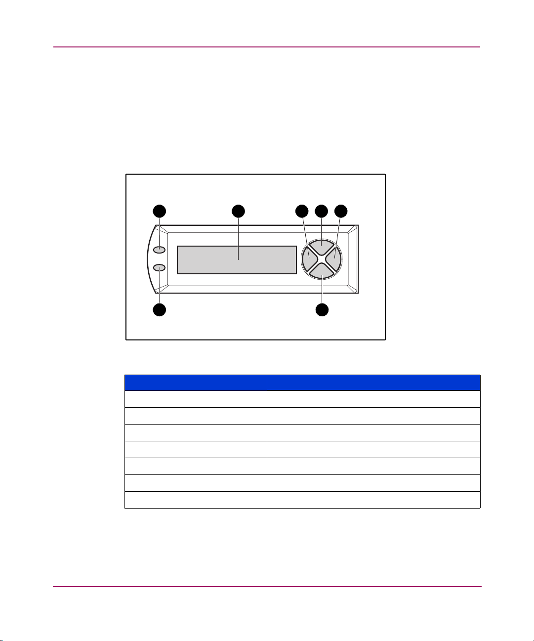
MSA1000 Controller Display
Each array controller in an MSA1000 contains an integrated Liquid Crystal
Display (LCD). This module is used for displaying informational and error
messages, showing the status of the module, and for providing user input when
required. Traditional Power-On Self-Test (POST) messages issued by PCI-based
array controllers have been combined with runtime event notification messages to
create a new set of controller display messages.
1 2 3 4 5
67
Figure 1: Controller display
\
Controller Display Description
1
2
3
4
5
6
7
Fault indicator (amber)
Display
Left push button
Up push button
Right push button
Down push button
Redundancy Link indicator (green)
For more information about the MSA1000 Controller display, see the “Controller
Display Messages” chapter.
12 MSA1000 Controller User Guide
Page 13

Array Accelerator (Battery-backed Cache)
The Array Accelerator is a high-performance, upgradeable 256-MB SDRAM
DIMM read/write battery-backed cache that can increase performance in database
and fault-tolerant configurations. It performs both protected posted-write caching
and read-ahead caching, allowing data to be accessed much faster than from disk
storage.
In protected posted-write caching, data is written to the cache memory on the
Array Accelerator rather than directly to the drives. Later, when the MSA1000
storage system is idle, the controller writes the cached data to the drive array.
The read-ahead cache detects sequential accesses to the array, reads ahead data,
and stores the data in the cache until the next read access arrives. If the data is of a
sequential nature, the data can be loaded immediately into memory, avoiding the
latency of a disk access.
If the MSA1000 Controller fails before cached data is stored on the disk, the
Array Accelerator and its integrated batteries may be removed from one
MSA1000 Controller and installed on a replacement controller. Any data in the
Array Accelerator that has not been written to the hard drive will be transferred to
the replacement MSA1000 Controller.
Array Accelerator Features
MSA1000 Controller
Other features of the Array Accelerator:
■ Mounted on a removable daughterboard (allows stored data to be moved to
another controller if the original controller fails)
■ Backed up with replaceable batteries
■ Upgradable to 512 MB (256 MB per controller)
■ Adjustable read/write ratio - usually set during array configuration but can be
changed at any time
■ 16-bit Error Checking and Correcting (ECC) SDRAM memory
ECC detects and corrects all single-bit memory errors. It also detects all
two-bit memory errors in any position, and most three- and four-bit memory
errors in a single SDRAM. With ECC, an entire memory chip can also fail
without data loss. This provides a high level of data integrity by ensuring the
correction of common memory errors without affecting performance.
13MSA1000 Controller User Guide
Page 14

MSA1000 Controller
Array Accelerator Batteries
The Array Accelerator has two rechargeable and replaceable Nickel Metal
Hydride (NiMH) battery packs. Under normal operating conditions, these should
last for three years before replacement is necessary. They are continuously
recharged via a “trickle” charging process whenever the MSA1000 storage system
is powered on.
The battery packs protect data on the Array Accelerator against equipment failure
or power outage for up to four continuous days.
Note: Temperature, age, and cache size may affect battery life.
This also applies if the Array Accelerator is removed from the MSA1000
Controller. When power is restored to the MSA1000 storage system, an
initialization process writes the preserved data to the disk drives. This is
particularly important for data that has been cached by a posted-write operation,
but has not yet been written to the hard drives.
Note: The batteries on a new MSA1000 Controller may be discharged when the
board is first installed. In this case, a Power-On Self-Test (POST) message will be
displayed on the controller display panel when the controller is powered on, indicating
that the Array Accelerator is temporarily disabled. No action is required on your part,
since the internal circuitry will automatically recharge the batteries. Recharging the
batteries can take up to 4 hours. The MSA1000 Controller will function properly during
this time, although without the performance advantage of the Array Accelerator. When
the batteries are charged to 90 percent of their capacity, the Array Accelerator is
automatically enabled.
Depending on the status of the array accelerator, including a low battery charge,
informational or error messages may be displayed on the controller’s LCD panel.
For a listing of cache module LCD messages, see the definitions for LCD
messages 60 through 79 in the “Controller Display Messages” chapter.
14 MSA1000 Controller User Guide
Page 15
Replacing the MSA1000 Controller Cache
Caution: It is important to follow these instructions when replacing
components in the MSA1000. If the procedure is done improperly, it is
possible to lose data or damage equipment. Refer to Appendix B,
“Electrostatic Discharge,” for important information on using the proper
procedures.
Note: If your system is equipped with a single controller, and you must replace the
controller cache, you must power down the system first. If your system is equipped with
two controllers, and you want to replace a failed cache module with another of the
same size, you can replace the module while the system is running. If your system is
equipped with two controllers, and you are replacing the cache module with a module
of a different size, you must power down the system first, and then change the cache
module on both controllers at the same time.
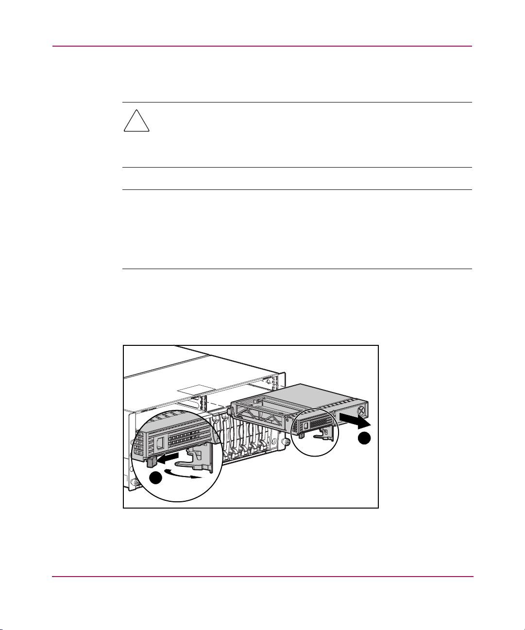
1. Press the controller’s thumb latch and pull the latch handle towards you 1.
See Figure 2.
2. Remove the MSA1000 Controller by pulling it straight out of the chassis 2.
MSA1000 Controller
1
Figure 2: Removing the controller
2
15MSA1000 Controller User Guide
Page 16
MSA1000 Controller
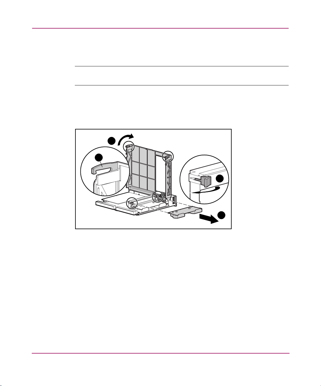
3. As illustrated in Figure 3, unlatch the controller cover clips 1 on the rear of
the controller and then raise the cover 2.
Note: The controller in Figure 3 has been rotated so the side and rear of the controller
are visible.
4. Simultaneously unlatch the clips that are holding the MSA1000 Controller
cache in place 3.
5. Carefully pull the cache away from the controller board 4.
2
1
3
4
Figure 3: Removing the cache module
16 MSA1000 Controller User Guide
Page 17
MSA1000 Controller
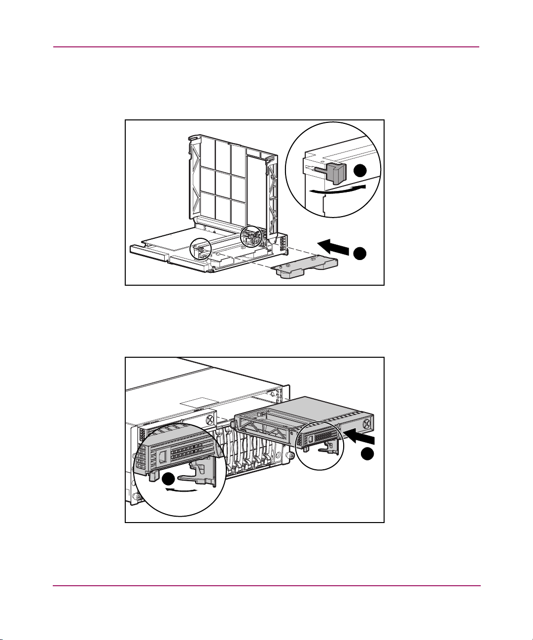
6. Install the new MSA1000 Controller cache by sliding the new MSA1000
Controller cache into the controller 1. Be sure the side latches are fully
engaged 2. See Figure 4.
2
1
Figure 4: Installing the cache module
7. Push the controller in as far as it will go 1; press the latch inward until it is
flush against the front panel 2. See Figure 5.
1
2
Figure 5: Installing the controller
17MSA1000 Controller User Guide
Page 18
MSA1000 Controller
Replacing the Controller Cache Battery Pack
WARNING: There is a risk of explosion, fire, or personal injury if the battery
pack is replaced incorrectly or mistreated. To reduce the risk:
■ Do not attempt to recharge the battery outside of the controller.
■ Do not expose to water, or to temperatures higher than 60°C.
■ Do not abuse, disassemble, crush, puncture, short external contacts, or
dispose of in fire or water.
■ Replace only with the spare designated for this product.
■ Array Accelerator battery disposal should comply with local regulations.
Alternatively, return them by established parts return methods to
Hewlett- Packard Corporation for disposal.
Caution: It is important to follow these instructions when replacing
components in the MSA1000. If the procedure is done improperly, it is
possible to lose data or damage equipment. Refer to the “Electrostatic
Discharge” appendix for important information on using the proper
procedures.
To remove the old NiMH battery pack:
1. Remove the MSA1000 Controller Cache, as instructed in the previous
section, “Replacing the MSA1000 Controller Cache.”
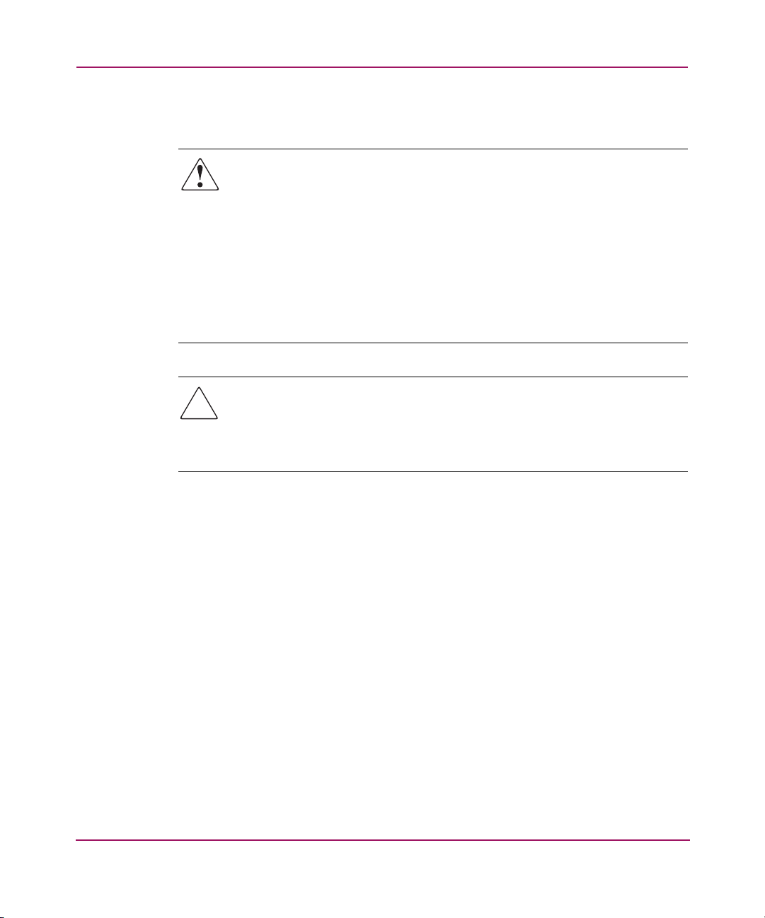
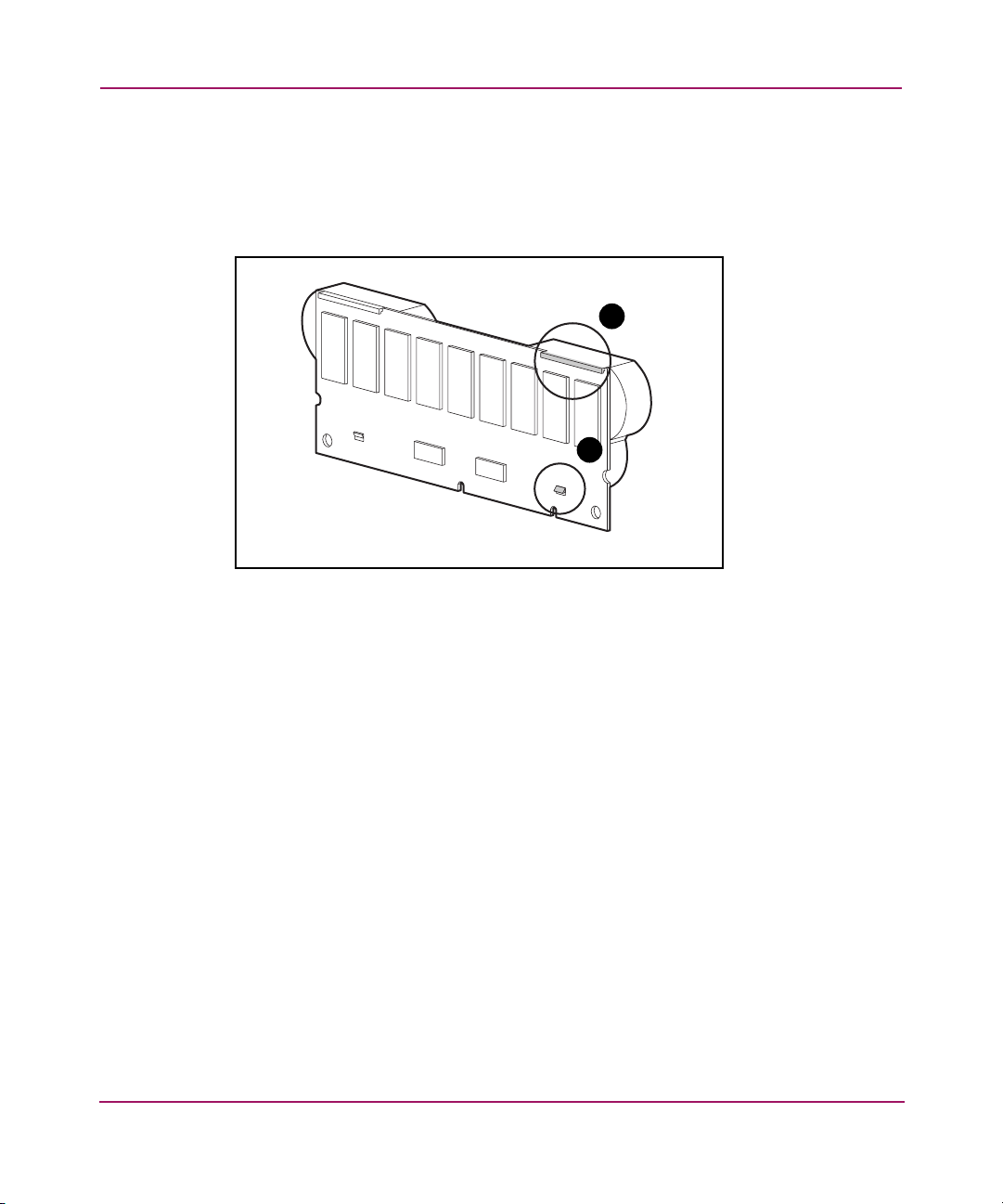
2. Push down on the bottom clip of the battery pack, attached near the lower
corner of the Array Accelerator.
See Figure 6 for an illustration.
18 MSA1000 Controller User Guide
Page 19
MSA1000 Controller
Figure 6: Bottom clip on battery pack
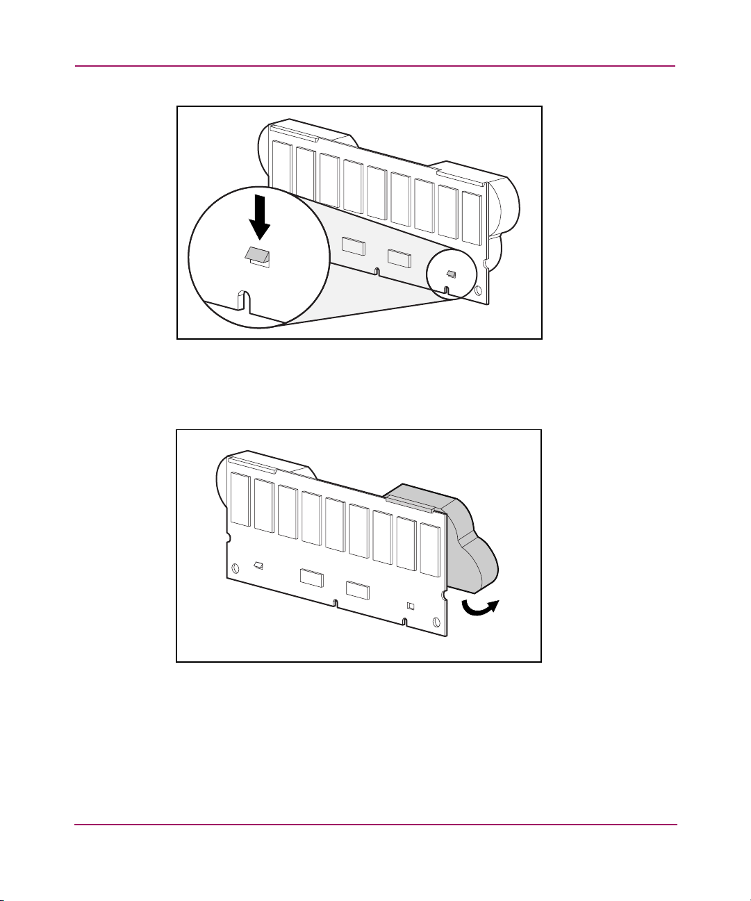
3. Swing the battery pack away from the Array Accelerator to about a 30-degree
angle.
Figure 7: Angling the battery pack
19MSA1000 Controller User Guide
Page 20
MSA1000 Controller
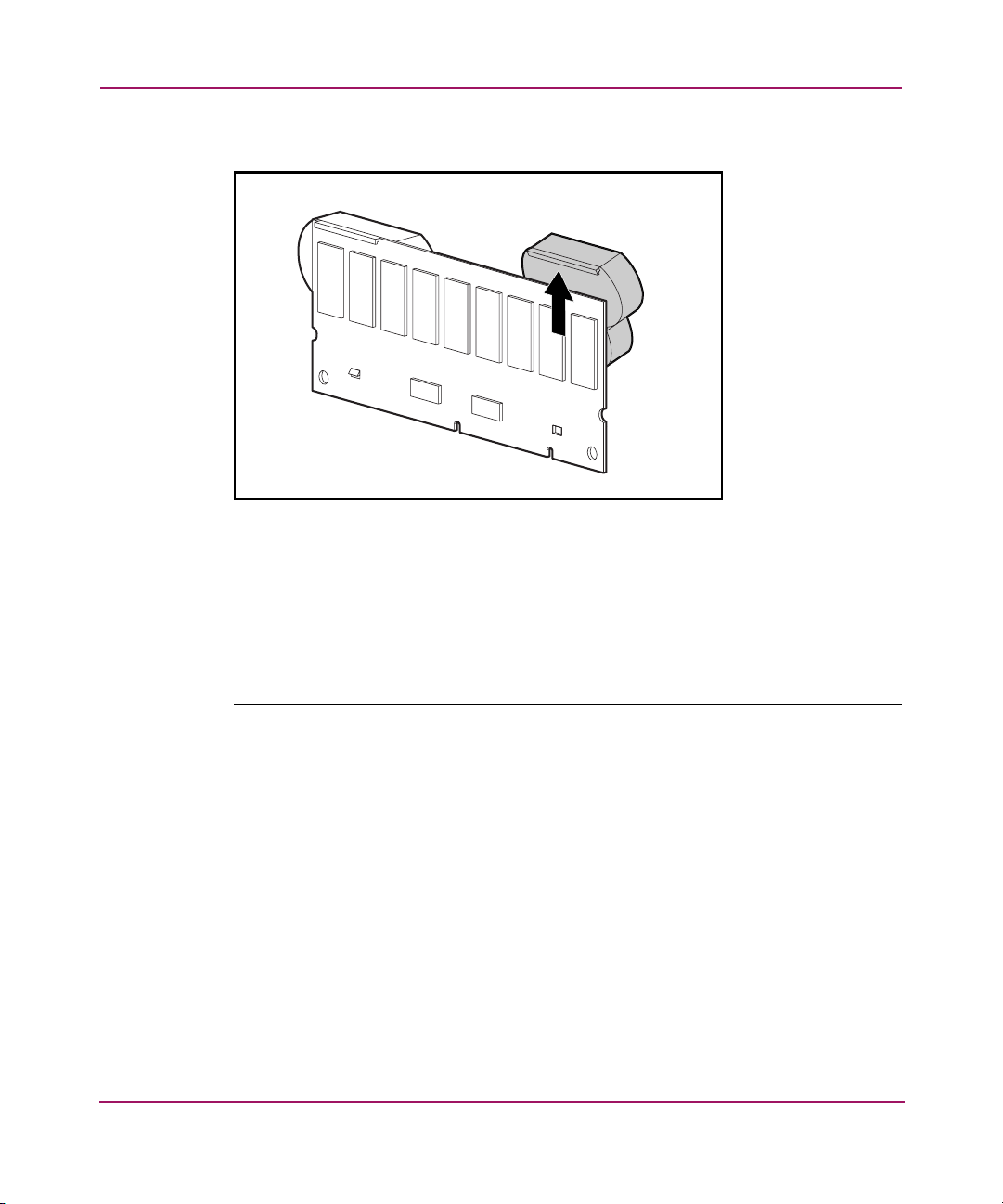
4. Lift the pack upward to unhook the top of the battery pack.
Figure 8: Removing the battery pack
Wait about 15 seconds after removing the old battery packs to allow the
battery charge monitor to reset.
Note: Repeat the replacement procedure for any batteries that were installed at the
same time as the batteries that were removed.
20 MSA1000 Controller User Guide
Page 21
MSA1000 Controller
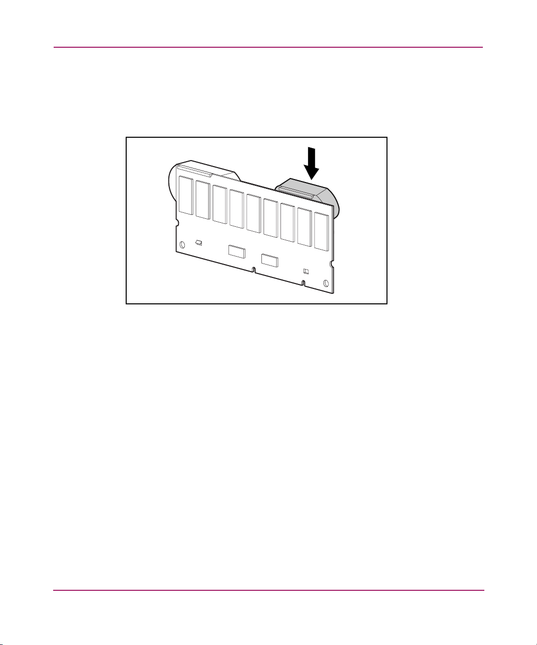
5. Install the new NiMH battery pack by hooking the top of the battery pack to
the top of the Array Accelerator with the pack held at a 30-degree angle to the
plane of the Array Accelerator board.
See Figure 9 for an illustration.
Figure 9: Installing the battery pack
21MSA1000 Controller User Guide
Page 22
MSA1000 Controller
6. After the pack is hooked in position, swing the pack downward making sure
the bottom clip and two pegs line up with the holes in the Array Accelerator.
7. Make sure that the top hook 1 and bottom clip 2 on the battery pack are
securely attached to the Array Accelerator.
1
2
Figure 10: Securing the battery pack
8. Installation of the new battery pack is complete. Repeat for the second battery
on this battery pack.
22 MSA1000 Controller User Guide
Page 23

Recovery ROM and ROM Cloning
Recovery ROM
Each MSA1000 Controller contains ROM (Read-Only Memory), which holds the
firmware that operates the controller. The Recovery ROM feature stores two
complete firmware images in the ROM: one active image and one backup image.
When the controller is powering up, it checks both firmware images to ensure
they are valid. If either one is not, the valid image will be copied on top of the
invalid image to correct it. This is referred to as auto-flashing. All of this
functionality is done automatically by the controller and does not require any user
intervention.
ROM Cloning
Note: For an MSA1000 to operate in a redundant controller configuration, it must
contain two controllers that are executing the same version of firmware. During power
up (or if an optional controller is hot-plugged while the MSA1000 is already
operating) the firmware versions on both controllers are compared. If they are not the
same, then the ROM Cloning feature will attempt to copy one version of firmware onto
the other controller. After the copy has been completed, the controller that was modified
will be automatically reset. Once the reset controller has powered up the two controllers
should then start redundant operation. All of this functionality is done automatically by
the controllers and does not require any user intervention.
MSA1000 Controller
The determination as to which firmware version will be used is based on the
following criteria:
■ If the MSA1000 is being powered up with both controllers inserted, then the
most recent version of firmware will be used regardless of which controller it
resides.
■ If the MSA1000 is already operating and an optional controller is
hot-plugged, then the version of firmware that is on the original
(non-hot-plugged) controller will be used regardless of its version. This
ensures that any host initiated I/O to the controller is not interrupted.
There is the possibility that a specific version of firmware may not be compatible
with certain hardware revisions of a controller. In this scenario, the most recent
firmware version that is compatible with both controllers will be copied to the
controller with the incompatible firmware version. However, if the controller that
23MSA1000 Controller User Guide
Page 24

MSA1000 Controller
is updated is already operating and processing I/O, then it will not be reset. The
MSA1000 will not enter redundant operation and an appropriate message will be
shown on the display. After the MSA1000 has been shutdown and powered back
on, the controllers will then be able to enter redundant operation. On a subsequent
power cycle, both controllers will enter redundant mode.
MSA1000 Controller Indicators
During normal runtime, the MSA1000 Controller has 18 indicators that indicate
activity or malfunction of the controller. They are labeled 0-17, as shown in the
following figure. The table that follows describes the purpose and function of each
indicator.
9 8 17101112131415
1 0 16234567
Figure 11: MSA1000 Controller indicators
24 MSA1000 Controller User Guide
Page 25

Table 2: MSA1000 Controller Indicator Descriptions
Indicator Function Description
0-2
Busy status These three LEDs are used to
progressively represent the processing
load on the controller.
ON = the controller is idle.
OFF = the controller is operating at full
capacity.
3-7
Fibre Channel ID Indicates the 5-bit Arbitrated Loop
Physical Address (ALPA) assigned to this
array controller (not applicable when in
fabric mode).
8 Idle Heartbeat Indicates the controller is idle and
functioning.
9
Active/Standby ON=Controller is active.
OFF=Controller is in standby.
-
Direct Memory Access
ON = DMA transfers are active.
(DMA) active
q
Logical I/O active ON = Currently processing logical
requests from the Host Adapter.
w
e
r
SCSI Port A (SCSI Bus 2)
SCSI Port B (SCSI Bus 3)
Cache Activity ON = Cache active.
ON = Indicates requests are outstanding
on the first SCSI bus.
ON = Indicates requests are outstanding
on the second SCSI bus.
OFF = No cache activity.
Blinking = Cache transfer pending.
t
Drive failure ON = A configured hard drive has
failed in the array.
@
A
Redundancy Active Green indicates two controllers are in a
redundant mode of operation.
Fault Amber indicates an error message has
been sent to the controller display.
MSA1000 Controller
25MSA1000 Controller User Guide
Page 26

MSA1000 Controller
Replacing the MSA1000 Controller
If an MSA1000 Controller is failing, informational or error messages will be
displayed on the LCD panel of that controller, depending on the condition.
The following steps detail how to replace a failed MSA1000 Controller but can
also be used to re-seat the controller.
Note: Redundancy is supported during a hard drive expansion, migration, or
extension process and during regular drive rebuilds.
Note: Replacement MSA1000 Controllers include a new cache module. Remove this
new module from the replacement MSA1000 Controller and replace it with the cache
module from the failed controller. Using the same cache module will complete the disk
writes that may have been trapped in the controller’s cache. See “Replacing the
MSA1000 Controller Cache” for procedural instructions.
1. Press the controller’s thumb latch and pull the latch handle toward you 1.
2. Remove the MSA1000 Controller by pulling it straight out of the chassis 2,
as illustrated in Figure 12.
2
1
Figure 12: Removing the MSA1000 Controller
26 MSA1000 Controller User Guide
Page 27

MSA1000 Controller
3. As illustrated in Figure 13, insert the replacement controller into the
chassis 1.
2
1
Figure 13: Installing the replacement controller
4. Push the controller in as far as it will go; press the latch inward until it is flush
against the front panel 2.
27MSA1000 Controller User Guide
Page 28

MSA1000 Controller
Updating the Controller Firmware
To load the latest version of the firmware for the MSA1000 Controller, go to the
HP website at
page, select the Software, Firmware & Drivers option.
Note: All supported operating systems obtain MSA1000 Controller firmware upgrades
from the HP website.
Installation instructions are available on the website.
You can use several methods to find out the version of the controller firmware you
are currently running:
■ On the MSA1000 Controller LCD panel, use the arrow keys to scroll
backwards through the messages.
Each time the MSA1000 storage system is restarted, the first message that is
displayed includes the firmware version.
■ In the CLI, use the SHOW VERSION command.
■ In the ACU, highlight the controller and view the details.
www.hp.com/go/msa1000
.
From the HP StorageWorks MSA1000
28 MSA1000 Controller User Guide
Page 29

Controller Display Messages
Each array controller in an MSA1000 contains an integrated display. This module
is used for displaying informational and error messages, showing the current
status of the module, and for providing user input when required. Traditional
Power-On-Self-Test (POST) messages issued by PCI-based array controllers have
been combined with runtime event notification messages to create a new set of
controller display messages.
The display module consists of the following components:
■ A two-line, twenty-column display text display window
■ Four push buttons arranged in a circular “pie” shape
■ Two status indicator lights
2
29MSA1000 Controller User Guide
Page 30

Controller Display Messages
About the LCD Messages
The display module is capable of holding up to 100 messages. Once this
maximum size has been reached, older messages will be removed to make room
for newer ones. Messages can be of three types: error, informational, and user
input.
The display message may specify a box number. The following box numbers are
defined.
■ Box 1 is the MSA1000 chassis.
■ Box 2 is the storage enclosure attached to SCSI port A of the MSA1000.
■ Box 3 is the storage enclosure attached to SCSI port B of the MSA1000.
Error Messages
Error messages indicate that a problem has occurred and may require user action
to correct it. A complete list of possible messages and their meanings is contained
in this appendix.
An amber indicator to the left of the display text display window will be turned on
when ever an error message is currently being viewed. This indicator will also be
turned on if an error message was sent to the display module but has not been
viewed because non-error type messages were sent to the display module
afterwards. By scrolling backwards and viewing all error messages, the indicator
will return to only lighting up when currently on an error message.
Informational Messages
Informational messages indicate non-critical changes in the system that are
provided as feedback to the user. A complete list of possible messages and their
meanings is contained in this appendix.
The amber indicator to the left of the display text display window will normally be
turned off whenever an informational message is currently being viewed unless an
unviewed error message was previously sent to the display module. By scrolling
backwards and viewing all error messages, the indicator will return to only
lighting up when currently on an error message.
User Input Messages
User input messages indicate that the system has encountered an issue that can be
handled in two different ways. It allows the user to either choose which way to
handle the issue or it will default to a standard choice after a set period of time.
30 MSA1000 Controller User Guide
Page 31

Scrolling
User Input
Controller Display Messages
These user input messages will only occur during system power on and not during
run time. A complete list of possible messages and their meanings is contained in
this appendix.
The amber indicator to the left of the display text display window will blink on
and off when a user input message is currently being viewed and is available for
input. If the user has not provided input within the time-out period, the message
will remain but the indicator will stop blinking.
Older messages can be viewed by scrolling backwards using the up push button
(with the up arrow on it). Messages that are more recent can be viewed by
scrolling forwards using the down push button (with the down arrow on it). The
last message can be viewed by pressing the left button. When a new message is
sent to the LCD, the display will show that message and ignore any previous
scrolling position. This new message is now the most recent message available.
User input messages will allow the user two options, which are selected by either
pushing the left push button (with the left arrow on it) or the right push button
(with the right arrow on it). The meaning of each button will be defined in the
display text display window.
Deleting Messages
The currently displayed message can be deleted from the display module by
pressing the left push button and the right push button at the same time.
Redundancy Link Light
There is a green indicator to the left of the display text display window that will be
lit when two array controllers have been inserted into the MSA1000 and they have
enabled controller redundancy. The indicator will not be lit if there is only one
array controller inserted or if the array controllers are not redundant due to some
type of failure.
Note: You must have redundant cables connected to enable redundancy.
31MSA1000 Controller User Guide
Page 32

Controller Display Messages
LCD Message Descriptions
The following table contains the defined messages and their components.
Table 3: LCD Message Descriptions
Message Type Description Action
00 ARRAY
CONTROLLER
FIRMWARE VER
<version>
01 MSA1000
STARTUP COMPLETE
02 ENABLE VOLUME
<n>? ‘<’=NO,
‘>’=YES
03 CRITICAL
LOCK-UP
DETECTED.
CODE=<n>h
04 ENABLE
VOLUMES ?
‘<’=NO, ‘>’=YES
Informational Displays the current version
Informational The array controller has
User Input An issue has been found
Error A critical error has been
User Input An issue has been found
of the firmware running on
the array controller.
completed its power on
sequence and is now
operational.
with a configured volume
that may result in data loss.
The exact nature of the
issue will be detailed in a
previous display message.
detected by the array
controller firmware. In
order to prevent any
possible data loss, the
firmware has entered a
lock-up state. The code
contains engineering
specific information about
the lock-up condition. HP
support should be
contacted.
with all of the configured
volumes that may result in
data loss. The exact nature
of the issue will be detailed
in a previous display
message.
Selecting the
result in the volume being
disabled so the user can
attempt to fix the issue.
Selecting the
will result in the volume
being enabled regardless
of the issue.
Remove the failing array
controller, wait 10 seconds,
and then reinsert it insuring
that it is fully seated in the
chassis.
Should the issue persist
please contact HP support.
An issue has been found
with all of the configured
volumes that may result in
data loss. The exact nature
of the issue will be detailed
in a previous display
message.
no
option will
yes
option
32 MSA1000 Controller User Guide
Page 33

Table 3: LCD Message Descriptions
Message Type Description Action
05 SYSTEM NAME:
Informational Displays the user assigned
<name>
06 RESTARTING
Informational Indicates that the system
SYSTEM
20 INITIALIZING
Informational The SCSI subsystem is
SCSI SUBSYSTEM
21 SCANNING FOR
Informational The firmware is searching
SCSI DEVICES
22 INITIALIZING
Informational The firmware is initializing
SCSI DEVICES
23 SCSI
Error The SCSI subsystem on
SUBSYSTEM
HARDWARE FAILURE
24 BAD SCSI BUS
Error The MSA1000 does not
MODE NON-LVD
DEVICE FOUND
name for the MSA1000
system. This name can be
assigned using the Array
Configuration Utility
(ACU).
has been reset and is being
restarted.
being initialized as part of
the power on sequence.
for SCSI devices attached
to the system as part of the
power on sequence.
all SCSI devices attached to
the system as part of the
power on sequence.
MSA1000 has experienced
a hardware failure and is
not operating correctly. The
array controller has halted
itself and cannot continue.
support SCSI Single Ended
(SE) devices, it only
supports SCSI Low Voltage
Differential (LVD) devices.
Controller Display Messages
Please contact HP support.
The MSA1000 should be
powered off and then all
SCSI devices attached to it
should be examined. Any
SE devices found should be
removed and replaced with
LVD devices.
33MSA1000 Controller User Guide
Page 34

Controller Display Messages
Table 3: LCD Message Descriptions
Message Type Description Action
30 I2C READ
Error The MSA1000 has a
FAILURE <I2C
device name>
31 I2C WRITE
Error The MSA1000 has a
FAILURE <I2C
device name>
32 CHASSIS NVRAM
Error The MSA1000 has
CONTENTS
CORRUPTED
40 BEGIN
Informational The array controllers are
REDUNDANCY
SUPPORT
number of internal devices
that are accessed via an
I2C hardware bus. One of
these devices failed when
attempting to read from it.
Certain I2C devices are
considered critical and will
result in a failure of the
array controller while
others may result in some
loss of functionality (such
as lost display messages).
number of internal devices
that are accessed via an
I2C hardware bus. One of
these devices failed when
attempting to write to it.
Certain I2C devices are
considered critical and will
result in a failure of the
array controller while
others may result in some
loss of functionality (such
as lost display messages).
non-volatile memory on it
that contains required
information which is
needed to operate. This
non-volatile memory
appears to be corrupted
and the information is not
valid. The MSA1000
cannot continue to operate
and will halt.
attempting to enter
redundant mode.
Should the issue persist
please contact HP support.
Should the issue persist
please contact HP support.
Please contact HP support.
34 MSA1000 Controller User Guide
Page 35

Table 3: LCD Message Descriptions
Message Type Description Action
41 REDUNDANCY
ACTIVE ACTIVE
CONTROLLER
42 REDUNDANCY
ACTIVE STANDBY
CONTROLLER
43 REDUNDANCY
FAILED HARDWARE
FAILURE
Informational The array controllers are
Informational The array controllers are
Error While either attempting to
now in redundant mode
and this array controller is
active
which means that it
is allowed to access the
configured volumes on the
MSA1000.
now in redundant mode
and this array controller is
standby
it can be made
should the current
array controller fail,
assuming you have all
cables, I/O module or
embedded switch installed.
enter redundant mode or
already operating in
redundant mode, one of
the array controllers
encountered a hardware
failure on the
communication channel
between the two array
controllers. Redundancy is
disabled at this time.
which means that
active
active
Controller Display Messages
If the MSA1000 is currently
involved in host I/O,
remove the
controller, wait 10 seconds,
and then reinsert it insuring
that it is fully seated in the
chassis.
If this does not resolve the
issue then wait until
down-time is available.
Power off the MSA1000,
remove both array
controllers and reinsert
them insuring they are fully
seated in the chassis.
Should the issue persist
please contact HP support.
standby
array
35MSA1000 Controller User Guide
Page 36

Controller Display Messages
Table 3: LCD Message Descriptions
Message Type Description Action
44 REDUNDANCY
Error Both array controllers must
FAILED MISMATCH
HARDWARE
45 REDUNDANCY
Error Both array controllers must
FAILED MISMATCH
FIRMWARE
contain the same hardware
for them to successfully
enter redundant mode. The
current array controllers do
not contain the same
hardware, possibly
because one has an
attached fibre daughter
card and the other does
not.
be running the same
version of firmware for
them to successfully enter
redundant mode. A
process called firmware
cloning that attempts to
make them both the same
firmware level has failed.
If the MSA1000 is currently
involved in host I/O,
remove the
standby
array
controller, add or remove
the fibre daughter card as
needed, wait 10 seconds,
and then reinsert it insuring
that it is fully seated in the
chassis.
If this does not resolve the
issue then wait until
down-time is available.
Power off the MSA1000,
remove both array
controllers, add or remove
fibre daughter cards as
needed on both, and
reinsert them insuring they
are fully seated in the
chassis.
Should the issue persist
please contact HP support.
Manually update the
firmware on the older array
controller.
36 MSA1000 Controller User Guide
Page 37

Table 3: LCD Message Descriptions
Message Type Description Action
47 REDUNDANCY
Error Both array controllers must
FAILED CACHE
SIZE MISMATCH
48 REDUNDANCY
Informational Both array controllers must
HALTED FIRMWARE
CLONED
have the same size of
cache memory for them to
successfully enter
redundant mode.
be running the same
version of firmware for
them to successfully enter
redundant mode. A
process called firmware
cloning has been
successfully completed in
order to make them both
the same firmware level.
The
standby
array
controller will now be
restarted automatically so
they can attempt to achieve
redundancy again.
Controller Display Messages
If the MSA1000 is currently
involved in host I/O,
remove the
standby
array
controller, add or remove
cache memory as needed,
wait 10 seconds, and then
reinsert it insuring that it is
fully seated in the chassis.
If this does not resolve the
issue then wait until
down-time is available.
Power off the MSA1000,
remove both array
controllers, add or remove
cache memory as needed
on both, and reinsert them
insuring they are fully
seated in the chassis.
Should the issue persist
please contact HP support.
37MSA1000 Controller User Guide
Page 38

Controller Display Messages
Table 3: LCD Message Descriptions
Message Type Description Action
49 REDUNDANCY
Error While either attempting to
FAILED FIRMWARE
LOCKUP
50 REDUNDANCY
Error While either attempting to
FAILED OUT OF
MEMORY
enter redundant mode or
already operating in
redundant mode, one of
the array controllers
encountered a critical
condition resulting in a
firmware lockup.
Redundancy is disabled at
this time.
enter redundant mode or
already operating in
redundant mode, one of
the array controllers failed
to allocate required
memory. Redundancy is
disabled at this time.
If the MSA1000 is currently
involved in host I/O,
remove the
standby
array
controller, wait 10 seconds,
and then reinsert it insuring
that it is fully seated in the
chassis.
If this does not resolve the
issue then wait until
down-time is available.
Power off the MSA1000,
remove both array
controllers, and reinsert
them insuring they are fully
seated in the chassis.
Should the issue persist
please contact HP support.
If the MSA1000 is currently
involved in host I/O,
remove the
standby
array
controller, wait 10 seconds,
and then reinsert it insuring
that it is fully seated in the
chassis.
If this does not resolve the
issue then you wait until
down-time is available.
Power off the MSA1000,
remove both array
controllers, and reinsert
them insuring they are fully
seated in the chassis.
Should the issue persist
please contact HP support.
38 MSA1000 Controller User Guide
Page 39

Table 3: LCD Message Descriptions
Message Type Description Action
51 REDUNDANCY
Error While either attempting to
FAILED I/O
REQUEST ERROR
52 REDUNDANCY
Error While either attempting to
FAILED PCI BUS
ERROR
53 REDUNDANCY
Error While operating in
FAILED NO SECOND
CONTROLLER
enter redundant mode or
already operating in
redundant mode, one of
the array controllers
encountered an error while
sending I/O between the
two array controllers over
the communication channel
between them. Redundancy
is disabled at this time.
enter redundant mode or
already operating in
redundant mode, one of
the array controllers
encountered a PCI bus
error on the communication
channel used between the
two array controllers.
Redundancy is disabled at
this time.
redundant mode, one of
the array controllers was
removed. Redundancy is
disabled at this time.
Controller Display Messages
If the MSA1000 is currently
involved in host I/O,
remove the
standby
array
controller, wait 10 seconds,
and then reinsert it insuring
that it is fully seated in the
chassis.
If this does not resolve the
issue then wait until
down-time is available.
Power off the MSA1000,
remove both array
controllers, and reinsert
them insuring they are fully
seated in the chassis.
Should the issue persist
please contact HP support.
If the MSA1000 is currently
involved in host I/O,
remove the
standby
array
controller, wait 10 seconds,
and then reinsert it insuring
that it is fully seated in the
chassis.
If this does not resolve the
issue then wait until
down-time is available.
Power off the MSA1000,
remove both array
controllers, and reinsert
them insuring they are fully
seated in the chassis.
Should the issue persist
please contact HP support.
Reinsert the missing array
controller insuring that it is
fully seated in the chassis.
39MSA1000 Controller User Guide
Page 40

Controller Display Messages
Table 3: LCD Message Descriptions
Message Type Description Action
54 REDUNDANCY
Error The cache memory
FAILED CACHE
DIMMS MISMATCH
60 NO CACHE
Error The array controller
MODULE FOUND
61 DUAL CACHE
Error The array controller has
MODULE SIZE
MISMATCH
62 CACHE MODULE
Informational Displays the size of the
#<n> <n>MB
63 VALID CACHE
Informational Valid host data was found
DATA FOUND AT
POWER-UP
64 CACHE DATA
Error The battery on the cache
LOST BATTERY
DEAD
modules on two different
controllers are not the same
size. All cache memory
modules must be the same
size for redundancy to
operate.
requires at least one cache
module in order to operate.
Either there is not one
present or it has failed.
two cache modules
attached but they are of
different sizes. Both cache
modules must be the same
size.
cache module inserted into
the respective cache
module slot.
in the battery backed cache
memory at power up. This
data has been flushed to
the drives.
memory was no longer
charged. If there was data
in the cache memory then it
has been lost.
Remove the array controller
that has been halted,
replace the cache modules
with the appropriately
sized ones, wait 10
seconds, and then reinsert
the array controller
insuring that it is fully
seated in the chassis.
Remove the failed array
controller, either add a
cache module or replace
the failed one, wait 10
seconds, and then reinsert
it insuring that it is fully
seated in the chassis.
Should the issue persist
please contact HP support.
Remove the failed array
controller, replace one of
the cache modules with a
different one that is of the
correct size, wait 10
seconds, and then reinsert
it, insuring that it is fully
seated in the chassis.
40 MSA1000 Controller User Guide
Page 41

Table 3: LCD Message Descriptions
Message Type Description Action
65 CACHE
Informational The cache hardware had
HARDWARE ENABLED
66 CACHE
Error The cache memory has
HARDWARE FAILED
AND DISABLED
67 CACHE
Informational The cache memory
HARDWARE
TEMPORARILY
DISABLED
been temporarily disabled
but is now enabled again.
This may have been due to
insufficient charge on the
batteries that have now
charged up to capacity.
experienced a hardware
failure.
hardware has temporarily
been disabled typically
because either the battery
is not charged up or a
capacity expansion
operation is occurring. The
cache will automatically be
enabled once the condition
has been corrected.
Controller Display Messages
If the failure has occurred
on the
standby
array
controller, then remove the
standby
array controller,
replace the cache modules,
wait 10 seconds, and then
reinsert the array controller
insuring that it is fully
seated in the chassis.
If the failure has occurred
on the
active
array
controller, then wait until
downtime is available.
Power off the MSA1000,
remove the array controller,
replace the cache modules,
and reinsert the array
controller insuring it is fully
seated in the chassis.
Should the issue persist
please contact HP support
41MSA1000 Controller User Guide
Page 42

Controller Display Messages
Table 3: LCD Message Descriptions
Message Type Description Action
68 OBSOLETE
Informational Old data that no longer
CACHE DATA
DELETED
69 CACHE
Informational The batteries on the cache
BATTERIES LOW,
RECHARGING
70 CACHE
Informational The cache has not been
DISABLED NO
CONFIGURATION
belongs to any current
configured volumes was
found in the cache memory
at power up. This data has
been deleted. This typically
happens if cache modules
are moved between array
controllers.
module are low and are
being recharged.
configured and therefore is
disabled. The cache can be
configured by using the
Array Configuration Utility
(ACU).
42 MSA1000 Controller User Guide
Page 43

Table 3: LCD Message Descriptions
Message Type Description Action
71 SYSTEM HALTED
FOR CACHE ERROR
Error This message is generated
if the user chooses to
ignore a critical cache error
condition. It is always
preceded by message #72
(although message #72 is
removed from the LCD
display once it has
accepted user input).
Controller Display Messages
The
no
option will cause
the array controller to halt
itself, providing the user an
opportunity to resolve the
issue. Selecting the
option will result in the
cache data being erased.
Operation of the array
controller will continue
normally.
Error
1.1
and
only one cache board in
the array controller at
present but it was
previously configured with
a second cache board that
is now missing (dual cache
module configuration).
Error
2.1
second cache board that
contained valid data was
removed from its original
array controller and added
to this array controller
(dual cache module
configuration). Error
cache board that
contained valid data was
removed from its original
array controller and added
to this array controller
(single cache module
configuration). Return all
cache boards to their
original array controllers.
Power up the systems
without allowing any host
I/O and wait for the cache
data to be written to the
drives. This will take a few
minutes after the systems
have finished the power on
sequence. The systems can
be powered off and cache
boards moved to their new
locations.
and
1.2
2.2
yes
: There is
: A
2.3
: A
43MSA1000 Controller User Guide
Page 44

Controller Display Messages
Table 3: LCD Message Descriptions
Message Type Description Action
72 CACHE ERROR
<n> IGNORE? <=NO
>=YES
User Input During power up, data was
found in the cache that
could not be flushed to the
drives. The reason is either
because the data does not
belong to this array
controller (the cache board
was moved from a different
array controller) or the
cache data is partial (the
rest of the data is in
another cache board that
was removed from the
array controller). This error
could occur if cache
boards are moved
improperly.
The
no
option will cause
the array controller to halt
itself, providing the user an
opportunity to resolve the
issue. Selecting the
option will result in the
cache data being erased.
Operation of the array
controller will continue
normally.
Error
1.1
2.1
and
and
only one cache board in
the array controller at
present but it was
previously configured with
a second cache board that
is now missing (dual cache
module configuration).
Error
second cache board that
contained valid data was
removed from its original
array controller and added
to this array controller
(dual cache module
configuration). Error
cache board that
contained valid data was
removed from its original
array controller and added
to this array controller
(single cache module
configuration). Return all
cache boards to their
original array controllers.
Power up the systems
without allowing any host
I/O and wait for the cache
data to be written to the
drives. This will take a few
minutes after the systems
have finished the power on
sequence. The systems can
be powered off and cache
boards moved to their new
locations.
1.2
2.2
yes
: There is
: A
2.3
: A
44 MSA1000 Controller User Guide
Page 45

Table 3: LCD Message Descriptions
Message Type Description Action
73 CACHE
Error The cache memory does
HARDWARE
BATTERIES
MISSING
80 REPLACEMENT
Informational A SCSI drive that was
DRIVE FOUND BOX
#<n> BAY <n>
81 SMART DRIVE
Informational A SCSI drive may be close
ALERT BOX #<n>,
BAY <n>
not have its required
batteries attached to it.
previously missing or failed
has now been replaced
with a working SCSI drive.
to failing. This was
determined either by the
drive firmware itself using
SMART technology or by
the array controller using
monitor and performance
testing.
Controller Display Messages
If the failure has occurred
on the
standby
array
controller, then remove the
standby
array controller,
replace the cache modules,
wait 10 seconds, and then
reinsert the array controller
insuring that it is fully
seated in the chassis.
If the failure has occurred
on the
active
array
controller, then wait until
down-time is available.
Power off the MSA1000,
remove the array controller,
replace the cache modules,
and reinsert the array
controller insuring it is fully
seated in the chassis.
Should the issue persist
please contact HP support.
The drive should be
replaced as soon as
possible following the
guidelines in Appendix E,
“Recovering from Hard
Drive Failure” in this guide.
82 DRIVE HOT
ADDED BOX #<n>,
BAY <n>
Informational A SCSI drive has been
added to the MSA1000 or
one of the storage
enclosures attached to it.
45MSA1000 Controller User Guide
Page 46

Controller Display Messages
Table 3: LCD Message Descriptions
Message Type Description Action
83 DRIVE HOT
Informational A SCSI drive has been
REMOVED BOX
#<n>, BAY <n>
removed from the
MSA1000 or one of the
storage enclosures attached
to it.
84 DRIVE FAILURE
BOX #<n>, BAY
<n> 84
85 BAD DRIVE
FRMWARE BOX
#<n>, BAY <n>
86 DRIVE
POSITION CHANGE
DETECTED
87 DRIVE
POSITION CHANGE
INVALID
Error A SCSI drive in the
MSA1000 or one of the
storage enclosures attached
to it has failed. If the drive
was part of a configured
volume, then the state of
the volume will depend on
the fault tolerance used.
Error A SCSI drive has been
detected that has known,
bad firmware on it.
Continued usage of this
drive could result in drive
failure, decreased
performance or data loss.
Informational The SCSI drives that make
up a configured volume
have been physically
moved within the
MSA1000 or an attached
storage enclosure. The
array controller has
updated its configuration
information accordingly.
Informational The SCSI drives that make
up a configured volume
have been physically
moved in such a way that
the array controller can no
longer access the
configured volume.
The drive should be
replaced as soon as
possible following the
guidelines in the
“Recovering from Hard
Drive Failure” section in
this guide (Appendix E).
Either the drive firmware
should be updated or the
drive should be replaced
as soon as possible
following the guidelines in
the “Recovering from Hard
Drive Failure” (Appendix E)
in this guide.
The MSA1000 should be
powered off and the drives
restored to their original
positions.
46 MSA1000 Controller User Guide
Page 47

Table 3: LCD Message Descriptions
Message Type Description Action
100 VOLUME #<n>
Informational The configured volume has
STATE OK
101 VOLUME #<n>
Error The configured volume has
STATE FAILED
102 VOLUME #<n>
Informational The array controller has
STATE INTERIM
RECOVERY
103 VOLUME #<n>
Informational The configured volume is
STATE REBUILDING
104 VOLUME #<n>
Error The configured volume has
STATE DISABLED
105 VOLUME #<n>
Informational The configured volume is
STATE EXPANSION
ACTIVE
returned to its normal
operating state. This
typically occurs after a
rebuild operation has
completed.
been failed because too
many SCSI drives that it is
composed of have failed
exceeding the fault
tolerance level. The data on
the configured volume is no
longer available.
failed one or more SCSI
drives that the configured
volume is composed of but
no data loss has occurred
because fault tolerance is
allowing the data to be
recovered.
rebuilding data on a SCSI
drive that replaced a
previously failed drive.
been disabled because too
many of the SCSI drives
that it is composed of are
missing.
currently performing a
volume expansion
operation.
Controller Display Messages
The failed drives should be
replaced as soon as
possible following the
guidelines in the
Recovering from Hard
Drive Failure
(Appendix E)
section in this guide.
Power off the MSA1000
and then all attached
storage enclosures. Unplug
and reinsert all SCSI drives
insuring they are fully
seated in their bays. Check
the cables connecting the
MSA1000 to any attached
storage enclosures. Power
on the attached storage
enclosures and then the
MSA1000.
47MSA1000 Controller User Guide
Page 48

Controller Display Messages
Table 3: LCD Message Descriptions
Message Type Description Action
106 VOLUME #<n>
Informational The configured volume is
STATE WAITING TO
REBUILD
107 VOLUME #<n>
Informational The configured volume is
STATE WAITING TO
EXPAND
108 VOLUME #<n>
Error The configured volume is
STATE MISSING
DRIVES
109 VOLUME #<n>
Error The configured volume
STATE WRONG
DRIVE REPLACED
waiting to start rebuilding
data on a SCSI drive that
replaces a previously failed
drive. The rebuild may not
have started yet because
the array controller is
already performing a
rebuild on another
configured volume.
waiting to start a volume
expansion operation. The
expansion may have not
started yet because another
configured volume is
undergoing expansion or a
rebuild is occurring on the
configured volume.
missing too many of the
SCSI drives that it is
composed of making it
unusable. The volume will
be disabled.
appears to have had
known, good SCSI drives
replaced instead of known,
failed drives.
Power off the MSA1000
and then all attached
storage enclosures. Unplug
and reinsert all SCSI drives
insuring they are fully
seated in their bays. Check
the cables connecting the
MSA1000 to any attached
storage enclosures. Power
on the attached storage
enclosures and then the
MSA1000.
The MSA1000 should be
powered off and the good
drives should be restored
while the failed drives
should be replaced.
48 MSA1000 Controller User Guide
Page 49

Table 3: LCD Message Descriptions
Message Type Description Action
110 VOLUME #<n>
Informational The volume expansion
EXPANSION
DISABLED
111 VOLUME #<n>
Informational The array controller is
INITIALIZING
PARITY
112 VOLUME #<n>
Error The rebuild operation on
REBUILD FAILURE
113 VOLUME #<n>
Error The volume expansion
EXPANSION
FAILURE
114 VOLUME #<n>
Informational The configured volume has
STATE DELETED
120 CONFIGURED
Informational The specified number of
VOLUMES <n>
operation on the
configured volume has
been disabled. This may be
because a rebuild
operation is ongoing,
another expansion is
already running, or the
cache memory is disabled
due to a low battery. The
expansion will start once
the condition has been
cleared.
calculating and storing
parity information for the
configured volume and
therefore performance may
be lower until it completes.
the configured volume has
failed.
operation on the
configured volume has
failed.
been deleted and is no
longer available. Volumes
are deleted by using the
Array Configuration Utility
(ACU).
configured volumes were
detected at power up.
Controller Display Messages
If the volume is still
operating in regenerative
mode, remove the new
SCSI drive that was added
as a replacement for the
original failed drive and
replace it with a different
new drive.
Run the Array
Configuration Utility (ACU)
and use it to determine the
state of the volume. If the
volume is still operational
then it is possible to
reattempt the operation.
49MSA1000 Controller User Guide
Page 50

Controller Display Messages
Table 3: LCD Message Descriptions
Message Type Description Action
121 NO VOLUMES
Informational No configured volumes
DETECTED
122 NEW
Informational Configured volumes from
VOLUME(S)
DETECTED
123 TOO MANY
Error The array controller only
VOLUMES DETECTED
were detected at power up.
another array controller
were migrated to this array
controller. The
configuration information
has been updated.
supports a maximum of 32
configured volumes. More
volumes then that were
detected at power up. This
typically occurs when
migrating a set of volumes
from one array controller to
a different array controller
that already has configured
volumes on it. The migrated
volumes have not been
added.
If there are supposed to be
configured volumes, power
off the MSA1000 and then
all attached storage
enclosures. Unplug and
reinsert all SCSI drives
insuring they are fully
seated in their bays. Check
the cables connecting the
MSA1000 to any attached
storage enclosures. Power
on the attached storage
enclosures and then the
MSA1000.
Remove the migrated drives
and run the Array
Configuration Utility
(ACU). Delete any
unneeded volumes until the
number of existing volumes
plus the number of
migrated volumes is 32 or
less. Add the migrated
drives back.
50 MSA1000 Controller User Guide
Page 51

Table 3: LCD Message Descriptions
Message Type Description Action
125 ACCESS
Error A set of volumes have been
CONTROL CONFLICT
DETECTED
126 ACCESS
Error A set of volumes have been
CONTROL
RESOURCES
EXCEEDED
201 ARRAY
Informational The temperature sensor on
CONTROLLER
TEMPERATURE OK
migrated from one array
controller to a different
array controller that
already has configured
volumes on it. The migrated
volumes have access
controls defined for them
that conflicts with the
existing configuration. The
access controls has been
modified so as to allow the
migration to proceed.
migrated from one array
controller to a different
array controllers that
already has configured
volumes on it. The migrated
volumes have access
controls defined for them
that conflicts with the
existing configuration. The
access controls has been
modified so as to allow the
migration to proceed.
the array controller
indicates that the
temperature which was
previously exceeding the
normal operating range is
now back within the range.
Controller Display Messages
Run the Array
Configuration Utility (ACU)
to check the new access
controls and modify them if
needed.
Run the Array
Configuration Utility (ACU)
to check the new access
controls and modify them if
needed.
51MSA1000 Controller User Guide
Page 52

Controller Display Messages
Table 3: LCD Message Descriptions
Message Type Description Action
202 ARRAY
Error The temperature sensor on
CONTROLLER
OVERHEATING
203 ARRAY
Error The temperature sensor on
CONTROLLER
OVERHEATED
204 ARRAY
Error The array controller has
CONTROLLER
DISABLED
205 ARRAY
Informational The array controller has
CONTROLLER
RESTARTING
the array controller
indicates that the array
controller is starting to
exceed the normal
operating range.
the array controller
indicates that the array
controller has exceeded the
safe operating range.
been disabled due to a
redundancy failure.
completed firmware
cloning and will be
restarted automatically.
Check all MSA1000 fans
and insure they are
operating. Any failed fans
should be replaced. Insure
that there are drive blank
cartridges in any empty
drive bays of the
MSA1000 chassis. If only
one array controller is
inserted, insure that there
are cover plates installed in
the empty array controller
bay and the fibre bay of
the MSA1000 chassis.
The MSA1000 should be
powered off as soon as
possible to avoid hardware
failure.
Check all MSA1000 fans
and insure they are
operating. Any failed fans
should be replaced. Insure
that there are drive blank
cartridges in any empty
drive bays of the
MSA1000 chassis. If only
one array controller is
inserted, insure that there
are cover plates installed in
the empty array controller
bay and the fibre bay of
the MSA1000 chassis.
Remove the failed array
controller, wait 10 seconds,
and then reinsert the array
controller insuring that it is
fully seated in the chassis.
Should the issue persist
please contact HP support.
52 MSA1000 Controller User Guide
Page 53

Table 3: LCD Message Descriptions
Message Type Description Action
300 RECOVERY ROM
Informational Indicates that the array
AUTOFLASH
STARTED
301 RECOVERY ROM
Informational Indicates that the array
AUTOFLASH DONE
302 RECOVERY ROM
Error Indicates that the array
AUTOFLASH FAILED
controller has detected that
the firmware’s backup
recovery ROM image is
invalid and is copying the
current active firmware
image into the backup
recovery ROM.
controller has successfully
completed the process of
copying the current active
firmware image into the
backup recovery ROM.
controller failed to copy the
current active firmware
image into the backup
recovery ROM. Recovery
ROM support is disabled.
Controller Display Messages
Remove the failing
array
controller, wait 10 seconds,
and then reinsert the array
controller insuring that it is
fully seated in the chassis.
The ROM autoflash process
will be attempted again.
Should the issue persist
please contact HP support.
53MSA1000 Controller User Guide
Page 54

Controller Display Messages
Table 3: LCD Message Descriptions
Message Type Description Action
303 ROM CLONING
Informational Indicates that the two array
STARTED
304 ROM CLONING
Informational Indicates that the two array
DONE
305 ROM CLONING
Error Indicates that the two array
FAILED
controllers in an MSA1000
do not have the same
version of firmware on
them. Therefore, one array
controller’s version of the
firmware will be copied on
to the other array
controller. Both controllers
must be running the same
version of fi rmware in order
for controller redundancy
to operate.
If both array controllers are
in the power up sequence,
then the most recent version
of firmware will be used.
If one array controller has
already completed the
power up sequence and is
now
active
, then its version
of firmware will be used
even if less recent.
controllers in an MSA1000
have finished copying one
array controller’s version of
firmware to the other array
controller. Both controllers
must be running the same
version of fi rmware in order
for controller redundancy
to operate.
controllers in an MSA1000
failed to copy one array
controller’s version of
firmware to the other array
controller. Both controllers
must be running the same
version of fi rmware in order
for controller redundancy
to operate.
Remove the
standby
array
controller, wait 10 seconds,
and then reinsert the array
controller insuring that it is
fully seated in the chassis.
The ROM cloning process
will be attempted again.
Should the issue persist
please contact HP support.
54 MSA1000 Controller User Guide
Page 55

Table 3: LCD Message Descriptions
Message Type Description Action
306 FIRMWARE
Informational Indicates that the array
FLASH STARTED
307 FIRMWARE
Informational Indicates that the array
FLASH DONE
308 FIRMWARE
Error Indicates that the array
FLASH FAILED
309 EMU FLASH
Informational Indicates that the EMU in
STARTED
310 EMU FLASH
Informational Indicates that the EMU in
DONE
311 EMU FLASH
Error Indicates that the EMU in
FAILED
400 STORAGE BOX
Informational The specified storage
#<n> FAN OK
controller in the MSA1000
has started the firmware
flash process. Do not turn
off power to the system until
it has completed. This could
take several minutes.
controller in the MSA1000
has completed the firmware
flash process. It is now safe
to turn off power to the
system.
controller in the MSA1000
has failed the firmware
flash process.
the MSA1000 has started
the firmware flash process.
Do not turn off the power to
the system until it has
completed. This could take
five minutes.
an MSA1000 has
completed the firmware
flash process. It is now safe
to turn off power to the
system.
an MSA1000 has failed
the firmware flash process.
enclosure indicates that one
of its fans which previously
had been failed or
degraded is now operating
normally.
Controller Display Messages
Attempt the flash process
again.
Should the issue persist,
please contact HP support.
Attempt the flash process
again.
Should the issue persist,
please contact HP support.
55MSA1000 Controller User Guide
Page 56

Controller Display Messages
Table 3: LCD Message Descriptions
Message Type Description Action
401 STORAGE BOX
Error The specified storage
#<n> FAN FAILED
402 STORAGE BOX
Error The specified storage
#<n> FAN
DEGRADED
403 STORAGE BOX
Informational The specified storage
#<n> FAN HOT
INSERTED
404 STORAGE BOX
Informational The specified storage
#<n> FAN HOT
REMOVED
405 STORAGE BOX
Informational The temperature sensor in
#<n> TEMPERATURE
OK
406 STORAGE BOX
Error The temperature sensor in
#<n> OVERHEATING
enclosure indicates that one
of its fans has failed. The
storage enclosure and any
devices in it may now be
susceptible to overheating
if corrective action is not
taken.
enclosure indicates that one
of its fans is not operating
at full efficiency. The fan
may eventually fail.
enclosure indicates that a
fan has been added.
enclosure indicates that a
fan has been removed.
the storage enclosure
indicates that the
temperature is now back in
the normal operating
range.
the storage enclosure
indicates that the enclosure
is starting to exceed the
normal operating range.
Check all fans and insure
they are operating. Any
failed fans should be
replaced.
Check all fans and insure
they are operating. Any
failed fans should be
replaced.
Check all fans and insure
they are operating. Any
failed fans should be
replaced. Insure that there
are drive blank cartridges
in any empty drive bays in
the enclosure. If the
enclosure is an MSA1000
and only one array
controller is inserted, insure
that there are cover plates
installed in the empty array
controller bay and the fibre
bay in the chassis.
56 MSA1000 Controller User Guide
Page 57

Table 3: LCD Message Descriptions
Message Type Description Action
407 STORAGE BOX
Error The temperature sensor in
#<n> OVERHEATED
408 STORAGE BOX
Informational The specified storage
#<n> POWER
SUPPLY OK
409 STORAGE BOX
Error The specified storage
#<n> POWER
SUPPLY FAILED
410 STORAGE BOX
Informational The specified storage
#<n> POWER
SUPPLY ADDED
411 STORAGE BOX
Informational The specified storage
#<n> POWER
SUPPLY REMOVED
the storage enclosure
indicates that the enclosure
has exceeded the safe
operating range.
enclosure indicates that one
of its power supplies which
previously had been failed
is now operating normally.
enclosure indicates that one
of its power supplies has
failed.
enclosure indicates that a
power supply has been
added.
enclosure indicates that a
power supply has been
removed.
Controller Display Messages
The MSA1000 should be
powered off as soon as
possible and immediately
after that, the enclosure
should be powered off, to
avoid hardware failure.
Check all fans and insure
they are operating. Any
failed fans should be
replaced. Insure that there
are drive blank cartridges
in any empty drive bays in
the enclosure. If the
enclosure is an MSA1000
and only one array
controller is inserted, insure
that there are cover plates
installed in the empty array
controller bay and the fibre
bay in the chassis.
Check all power supplies
and insure they are
operating. Any failed
power supplies should be
replaced.
57MSA1000 Controller User Guide
Page 58

Controller Display Messages
Table 3: LCD Message Descriptions
Message Type Description Action
412 STORAGE BOX
Error The specified storage
#<n> EMU NOT
RESPONDING
413 STORAGE BOX
Informational The version of the firmware
#<n> EMU VERSION
<version>
415 STORAGE BOX
Informational A HP StorageWorks SCSI
#2 OR #3 HOT
ADDED
500 INITIALIZING
Informational The array controller’s PCI
PCI SUBSYSTEM
501 PCI
Error The array controller’s PCI
SUBSYSTEM
HARDWARE FAILURE
502 PCI BRIDGE
Error The array controller’s PCI
ASIC SELF TEST
FAILURE
enclosure is not responding
to commands.
running on the EMU. This is
only displayed for the
internal EMU of the
MSA1000. It is not
displayed for externally
connected storage boxes.
expansion storage
enclosure has been
hot-added to the
MSA1000.
subsystem is being
initialized as part of the
power up sequence.
subsystem has encountered
a critical error during the
power up sequence.
bridge ASIC has
encountered a critical error
during the power up
sequence.
Insure the storage box is
powered on. Insure all
cables are connected
securely. Power of the
MSA1000 and the storage
box. Power on the storage
box first and then the
MSA1000.
Should the issue persist,
please contact HP support.
Remove the failed array
controller, wait 10 seconds,
and then reinsert the array
controller insuring that it is
fully seated in the chassis.
Should the issue persist
please contact HP support.
Remove the failed array
controller, wait 10 seconds,
and then reinsert the array
controller insuring that it is
fully seated in the chassis.
Should the issue persist
please contact HP support.
58 MSA1000 Controller User Guide
Page 59

Table 3: LCD Message Descriptions
Message Type Description Action
510 INITIALIZING
Informational The array controller’s fibre
FIBRE SUBSYSTEM
513 UNCORRECTED
Error The array controller has
ECC MEMORY ERROR
SEEN
514 FIBRE SWITCH
Error The MSA SAN Switch 2/8
HARDWARE FAILURE
subsystem is being
initialized as part of the
power up sequence.
detected an uncorrectable
error in the ECC memory
on the memory cache
board.
that is installed in the
MSA1000 failed to
establish a connection with
the array controller over
fibre channel.
Controller Display Messages
Remove the failed array
controller and replace the
memory cache board with
a new one.
Remove the MSA Fabric
Switch 6 switch, wait one
minute and then reinsert it
insuring it is fully seated in
the chassis. Wait one
minute and check the LCD
to see if a new copy of this
error message is created.
The service indicator LED
on the back of the switch
should turn solid green if
the switch is operating
normally. The service
indicator LED will flash
amber if it has failed
again.
Should the issue persist
please contact HP support.
59MSA1000 Controller User Guide
Page 60

Controller Display Messages
Table 3: LCD Message Descriptions
Message Type Description Action
515 FIBRE DEVICE
Error The fibre device that is
HARDWARE FAILURE
516 FIBRE
Error There is no active fibre
SUSBYSTEM LINK
FAILURE
517 FIBRE
Informational There is an active fibre
SUBSYSTEM LINK
OK
installed in the MSA1000
fibre bay was not
recognized by the array
controller.
connection to this
MSA1000 array controller
(Laser OFF).
If the Fibre connection is a
direct-connect from an
HBA to the MSA1000, this
message is expected when
the server is powered off or
restarted.
connection to this
MSA1000 array controller
(Laser On).
This message is only
displayed when preceded
by message 516.
Verify the fibre device is
supported by the
MSA1000 by checking the
documentation that came
with it. If it is supported
then remove the fibre
device, wait one minute
and then reinsert it insuring
it is fully seated in the
chassis. Wait one minute
and check the LCD to see if
a new copy of this error
message is created. The
service indicator LED on
the back of the switch
should turn solid green if
the device is operating
normally. The service
indicator LED will flash
amber if it has failed
again.
Should the issue persist,
please contact HP support.
Power on the server and
load the HBA drivers.
If the status does not
change to OK, check
cables, fibre bay board,
SFP, and HBA.
60 MSA1000 Controller User Guide
Page 61

Table 3: LCD Message Descriptions
Message Type Description Action
518 PERSISTENT
Informational Global variables such as
MEM ENABLED
Controller Display Messages
system prompts and profile
information remain
persistent in cache over
power cycles of the
MSA1000.
This message is displayed
each time the MSA1000 is
powered up.
61MSA1000 Controller User Guide
Page 62

Controller Display Messages
62 MSA1000 Controller User Guide
Page 63

Regulatory Compliance Notices
Regulatory Compliance Identification Numbers
For the purpose of regulatory compliance certifications and identification, your
HP StorageWorks MSA1000 is assigned an HP Series number. The Storage
System Series number can be found on the product label, along with the required
approval markings and information. The product label is located on the right side
of the chassis. When requesting certification information for this product, always
refer to this Series number. This Series number should not be confused with the
marketing name or model number for your Storage System.
Federal Communications Commission Notice
This equipment has been tested and found to comply with the limits for a Class A
digital device, pursuant to Part 15 of the FCC Rules. These limits are designed to
provide reasonable protection against harmful interference when the equipment is
operated in a commercial environment. This equipment generates, uses, and can
radiate radio frequency energy and, if not installed and used in accordance with
the instructions, may cause harmful interference to radio communications.
Operation of this equipment in a residential area is likely to cause harmful
interference, in which case the user will be required to correct the interference at
personal expense.
A
Modifications
Cables
The FCC requires the user to be notified that any changes or modifications made
to this device that are not expressly approved by Hewlett-Packard Company may
void the user's authority to operate the equipment.
Connections to this device must be made with shielded cables with metallic
RFI/EMI connector hoods in order to comply with FCC Rules and Regulations.
63MSA1000 Controller User Guide
Page 64

Regulatory Compliance Notices
Canadian Notice (Avis Canadien)
This Class A digital apparatus meets all requirements of the Canadian
Interference-Causing Equipment Regulations.
Cet appareil numérique de la classe A respecte toutes les exigences du Règlement
sur le matériel brouilleur du Canada.
European Union Notice
Products with the CE Marking comply with both the EMC Directive
(89/336/EEC) and the Low Voltage Directive (73/23/EEC) issued by the
Commission of the European Community.
Compliance with these directives implies conformity to the following European
Norms (in brackets are the equivalent international standards):
■ EN55022 (CISPR 22) - Electromagnetic Interference
■ EN50082-1 (IEC801-2, IEC801-3, IEC801-4) - Electromagnetic Immunity
■ EN60950 (IEC950) - Product Safety
Japanese Notice
64 MSA1000 Controller User Guide
Page 65

BSMI Notice
Laser Compliance
The SFP Module contains a laser diode of either gallium aluminum arsenide
(GaALAs) emitting in the wavelength range of 770-860 nm, or indium gallium
arsenide phosphide (InGaAsP) emitting in the wavelength range of 1270-1355
nm. All HP systems equipped with a laser device comply with safety standards,
including International Electrotechnical Commission (IEC) 825. With specific
regard to the laser, the equipment complies with laser product performance
standards set by government agencies as a Class 1 laser product. The product does
not emit hazardous laser radiation.
Regulatory Compliance Notices
WARNING: Use of controls or adjustments or performance of procedures
other than those specified herein or in the laser product’s installation guide
may result in hazardous radiation exposure. To reduce the risk of exposure to
hazardous radiation:
■ Do not try to open the unit enclosure. There are no user-serviceable
components inside.
■ Do not operate controls, make adjustments, or perform procedures to the
laser device other than those specified herein.
■ Allow only HP Authorized Service technicians to repair the unit.
The Center for Devices and Radiological Health (CDRH) of the U.S. Food and
Drug Administration implemented regulations for laser products on August 2,
1976. These regulations apply to laser products manufactured from August 1,
1976. Compliance is mandatory for products marketed in the United States. This
device is classified as a Class 1 laser product as defined by IEC 825.
65MSA1000 Controller User Guide
Page 66

Regulatory Compliance Notices
Battery Replacement Notice
Your MSA1000 is provided with a Nickel Metal Hydride, Lithium Manganese
Dioxide, or a Vanadium Pentoxide, batteries. There is a danger of explosion and
risk of personal injury if the array is incorrectly replaced or mistreated. Replace
only with the HP spare designated for this product. For more information about
battery replacement or proper disposal, contact your HP Authorized Reseller or
your Authorized Service Provider.
WARNING: Your Accelerator Array contains Lithium manganese Dioxide, or
Vanadium Pentoxide batteries. There is risk of fire and burns if the battery pack
is not handled properly. To reduce the risk of personal injury:
■ Do not attempt to recharge the battery.
■ Do not expose to temperatures higher than 60 C.
■ Do not disassemble, crush, puncture, short external contacts, or dispose of
in fire or water.
■ Replace only with HP spare designated for this product.
This indicates that the product is classified as a
CLASS 1 LASER PRODUCT.
Caution: Batteries, battery packs, and accumulators should not be disposed of
together with the general household waste. In order to forward them to
recycling or proper disposal, please use the public collection system or return
them to HP, your authorized HP Partners, or their agents.
66 MSA1000 Controller User Guide
Page 67

Electrostatic Discharge
To prevent damage to the system, be aware of the precautions you need to follow
when setting up the system or handling parts. A discharge of static electricity from
a finger or other conductor may damage system boards or other static-sensitive
devices. This type of damage may reduce the life expectancy of the device.
To prevent electrostatic damage, observe the following precautions:
■ Avoid hand contact by transporting and storing products in static-safe
containers.
■ Keep electrostatic-sensitive parts in their containers until they arrive at
static-free workstations.
■ Place parts on a grounded surface before removing them from their
containers.
■ Avoid touching pins, leads, or circuitry.
■ Always make sure you are properly grounded when touching a static-sensitive
component or assembly.
B
67MSA1000 Controller User Guide
Page 68

Electrostatic Discharge
Grounding Methods
There are several methods for grounding. Use one or more of the following
methods when handling or installing electrostatic-sensitive parts:
■ Use a wrist strap connected by a ground cord to a grounded workstation or
computer chassis. Wrist straps are flexible straps with a minimum of 1
megohm ± 10 percent resistance in the ground cords. To provide proper
ground, wear the strap snug against the skin.
■ Use heel straps, toe straps, or boot straps at standing workstations. Wear the
straps on both feet when standing on conductive floors or dissipating floor
mats.
■ Use conductive field service tools.
■ Use a portable field service kit with a folding static-dissipating work mat.
If you do not have any of the suggested equipment for proper grounding, have an
Authorized HP Reseller install the part.
Note: For more information on static electricity, or assistance with product installation,
contact your HP Authorized Reseller.
68 MSA1000 Controller User Guide
Page 69

Index
A
array
accelerator batteries, installing 18
array accelerator
described 13
features of 13
audience 6
B
batteries
replacement notice 66
replacing 18
warnings 18
C
chassis 26
Controller
removing 26
Controller display
box numbering 30
components 29
defined 29
deleting messages 31
error messages 30
informational messages 30
message types 30
redundancy link light 31
user input messages 30, 31
Controller display messages
access control conflict detected 51
access control resources exceeded 51
array Controller disabled 52
Index
Index
array Controller overheated 52
array Controller overheating 52
array Controller restarting 52
array Controller temperature ok 51
bad drive firmware box, bay 46
bad SCSI bus mode non-lvd device found 33
begin redundancy support 34
cache batteries low recharging 42
cache data lost battery dead 40
cache disabled no configuration 42
cache error 44
cache hardware batteries missing 45
cache hardware enabled 41
cache hardware temporarily disabled 41
cache module size 40
chassis nvram contents corrupted 34
configured volumes 49
critical lockup detected 32
drive failure box, bay 46
drive hot added box, bay 45
drive hot removed box, bay 46
drive position change detected 46
drive position change invalid 46
dual cache module size mismatch 40
EMU flash done 55
EMU flash failed 55
EMU flash started 55
enable volume 32
enable volumes 32
fibre switch hardware failure 59
firmware flash done 55
firmware flash failed 55
firmware flash started 55
69MSA1000 Controller User Guide
Page 70

Index
firmware version 32
initializing fibre subsystem 59
initializing PCI subsystem 58
initializing SCSI devices 33
initializing SCSI subsystem 33
new volume(s) detected 50
no cache module found 40
no volumes detected 50
obsolete cache data deleted 42
PCI bridge ASIC self-test failure 58
PCI subsystem hardware failure 58
read failure 34
recovery ROM autoflash done 53
recovery ROM autoflash failed 53
recovery ROM autoflash started 53
redundancy active active Controller 35
redundancy active standby Controller 35
redundancy failed cache DIMMS mismatch
40
redundancy failed cache size mismatch 37
redundancy failed firmware lockup 38
redundancy failed hardware failure 35
redundancy failed I/O request error 39
redundancy failed mismatch firmware 36
redundancy failed mismatch hardware 36
redundancy failed no second Controller 39
redundancy failed out of memory 38
redundancy failed PCI bus error 39
redundancy halted firmware cloned 37
replacement drive found box 45
restarting system 33
ROM cloning done 54
ROM cloning failed 54
ROM cloning started 54
scanning for SCSI devices 33
SCSI subsystem hardware failure 33
smart drive alert box 45
startup complete 32
storage box 55
storage box EMU not responding 58
storage box EMU version 58
storage box fan failed 56
storage box fan hot inserted 56
storage box fan hot removed 56
storage box overheated 57
storage box overheating 56
storage box power supply added 57
storage box power supply failed 57
storage box power supply ok 57
storage box power supply removed 57
storage box temperature ok 56
storage fan degraded 56
system halted for cache error 43
system name 33
too many volumes detected 50
uncorrected ECC memory error seen 59
valid cache data found at power-up 40
volume expansion disabled 49
volume expansion failure 49
volume initializing parity 49
volume rebuild failure 49
volume state deleted 49
volume state disabled 47
volume state expansion active 47
volume state failed 47
volume state ok 47
volume state rebuilding 47
volume state waiting to expand 48
volume state waiting to rebuild 48
volume state wrong drive replaced 48
volumestate interim recovery 47
volumestate missing drives 48
write failure 34
conventions
document 7
equipment symbols 8
text symbols 7
D
document
conventions 7
documentation, related 6
70 MSA1000 Controller User Guide
Page 71

Index
E
electrostatic discharge 67
equipment symbols 8
F
FCC notice 63
firmware
updating 28
G
getting help 10
grounding methods 68
H
help, obtaining 9
hp
authorized reseller 10
technical support 10
website 10
I
installing
batteries 18
replacing 26
securing 27
P
panels
rear 27
R
rack stability, warning 9
recovery ROM 23
regulatory compliance identification numbers
63
regulatory compliance notices 64
related documentation 6
replacing
batteries 18
ROM
cloning 11
recovery 11
S
symbols in text 7
symbols on equipment 8
M
MSA1000 Controller
array accelerator 13
array accelerator features 13
ejector levers 15, 26
failure 26
indicators 24
installing 27
latches 15, 26, 27
removing 26
MSA1000 Controller User Guide 71
T
technical support, hp 10
text symbols 7
W
warning
rack stability 9
symbols on equipment 8
websites
hp storage 10
Page 72

Index
72 MSA1000 Controller User Guide
 Loading...