

Page 1

HPE Smart Array P824i-p MR Gen10 User Guide
Abstract
This document includes feature, installation, and configuration information about Hewlett
Packard Enterprise Smart Array P824i-p MR Gen10 controller and is for the person who
installs, administers, and troubleshoots servers and storage systems. Hewlett Packard
Enterprise assumes you are qualified in the servicing of computer equipment and trained in
recognizing hazards in products with hazardous energy levels.
Part Number: P06372-002
Published: March 2019
Edition: 2
Page 2

©
Copyright 2018, 2019 Hewlett Packard Enterprise Development LP
Notices
The information contained herein is subject to change without notice. The only warranties for Hewlett
Packard Enterprise products and services are set forth in the express warranty statements accompanying
such products and services. Nothing herein should be construed as constituting an additional warranty.
Hewlett Packard Enterprise shall not be liable for technical or editorial errors or omissions contained
herein.
Confidential computer software. Valid license from Hewlett Packard Enterprise required for possession,
use, or copying. Consistent with FAR 12.211 and 12.212, Commercial Computer Software, Computer
Software Documentation, and Technical Data for Commercial Items are licensed to the U.S. Government
under vendor's standard commercial license.
Links to third-party websites take you outside the Hewlett Packard Enterprise website. Hewlett Packard
Enterprise has no control over and is not responsible for information outside the Hewlett Packard
Enterprise website.
Acknowledgments
Microsoft® and Windows® are either registered trademarks or trademarks of Microsoft Corporation in the
United States and/or other countries.
MegaRAID™ and CacheCade™ are registered trademarks of Broadcom, Inc.
Linux ® is the registered trademark of Linus Torvalds in the U.S. and other countries.
Page 3

Contents
HPE Smart Array P824i-p MR Gen10.....................................................5
Features................................................................................................... 6
Controller supported features....................................................................................................... 6
Operating environments.....................................................................................................6
RAID technologies..............................................................................................................6
Transformation................................................................................................................... 7
Drive technology.................................................................................................................7
Security.............................................................................................................................. 7
Reliability............................................................................................................................7
Performance.......................................................................................................................7
RAID technologies........................................................................................................................ 8
Selecting the right RAID type for your IT infrastructure......................................................8
Mixed mode (RAID and JBOD simultaneously)............................................................... 12
Make Unconfigured Good and Make JBOD.....................................................................12
Patrol read........................................................................................................................12
Striping............................................................................................................................. 12
Mirroring........................................................................................................................... 13
Parity................................................................................................................................ 15
Spare drives..................................................................................................................... 19
Drive rebuild..................................................................................................................... 20
Foreign configuration import............................................................................................ 20
Transformation............................................................................................................................20
Array transformations.......................................................................................................20
Logical drive transformations........................................................................................... 20
Drive technology......................................................................................................................... 21
HPE SmartDrive LED.......................................................................................................21
Consistency check........................................................................................................... 23
Online drive firmware update........................................................................................... 23
Discarding pinned cache..................................................................................................23
Dynamic sector repair...................................................................................................... 23
Security....................................................................................................................................... 24
Drive erase.......................................................................................................................24
Sanitize erase...................................................................................................................24
Reliability.....................................................................................................................................25
Recovery ROM.................................................................................................................25
Cache Error Checking and Correction (ECC).................................................................. 25
Thermal monitoring.......................................................................................................... 25
Performance................................................................................................................................25
SAS storage link speed....................................................................................................25
HPE Smart Array MR FastPath........................................................................................25
HPE Smart Array MR CacheCade................................................................................... 26
Cache...............................................................................................................................26
Installation............................................................................................. 29
Installation...................................................................................................................................29
Installing an HPE Smart Array P824i-p MR Gen10 controller in a configured server...... 29
3
Page 4

Installing an HPE Smart Array P824i-p MR Gen10 controller in an unconfigured
server............................................................................................................................... 30
Configuring boot controller options.................................................................................. 31
Connecting storage devices.............................................................................................33
Cable part numbers..........................................................................................................33
Configuration.........................................................................................34
Array and controller configuration............................................................................................... 34
HPE MR Storage Administrator........................................................................................34
StorCLI............................................................................................................................. 35
UEFI System Utilities........................................................................................................35
Smart Array MR Gen10 configuration in UEFI System Utilities.................................................. 36
Viewing controller information and performing common actions......................................36
Configuration management..............................................................................................37
Controller management....................................................................................................43
Logical drive management............................................................................................... 50
Drive management...........................................................................................................52
Maintenance.......................................................................................... 58
System maintenance tools..........................................................................................................58
Updating software and firmware...................................................................................... 58
Diagnostic tools................................................................................................................58
Models....................................................................................................59
HPE Smart Array P824i-p MR Gen10 Controller........................................................................ 59
Energy pack options.............................................................................60
HPE Smart Storage Battery........................................................................................................ 60
HPE Smart Storage Hybrid Capacitor.........................................................................................60
Energy pack specifications......................................................................................................... 61
Specifications........................................................................................62
Memory and storage capacity conventions.................................................................................62
RAID conventions....................................................................................................................... 62
Controller specifications..............................................................................................................62
Support and other resources...............................................................63
Accessing Hewlett Packard Enterprise Support......................................................................... 63
Accessing updates......................................................................................................................63
Customer self repair....................................................................................................................64
Remote support.......................................................................................................................... 64
Warranty information...................................................................................................................64
Regulatory information................................................................................................................65
Documentation feedback............................................................................................................ 65
Websites................................................................................................ 66
4
Page 5
HPE Smart Array P824i-p MR Gen10
HPE Smart Array P824i-p MR Gen10 is ideal for maximizing performance while supporting advanced
RAID levels. This controller operates in Mixed Mode which combines RAID and JBOD operations
simultaneously. It offers flash-backed write cache and read-ahead cache and provides enterprise-class
storage performance, reliability, security, and efficiency.
HPE Smart Array P824i-p MR Gen10 provides:
• 24 SAS lanes across 6 x4 internal Mini SAS HD ports
• SAS and SATA drive support
• RAID levels 0, 1, 5, 6, 10, 50, 60
• Mixed mode RAID and JBOD functionality simultaneously
• 12G SAS support
• UEFI and Legacy Boot modes
• 4 GB flash-backed write cache support
• HPE Smart Storage Battery support
• HPE Smart Storage Hybrid Capacitor support
• Smart Array management tools:
◦ HPE MR Storage Administrator
◦ HPE StorCLI
◦ UEFI Storage Configuration Utility
HPE Smart Array P824i-p MR Gen10 is supported in HPE ProLiant Gen10 servers.
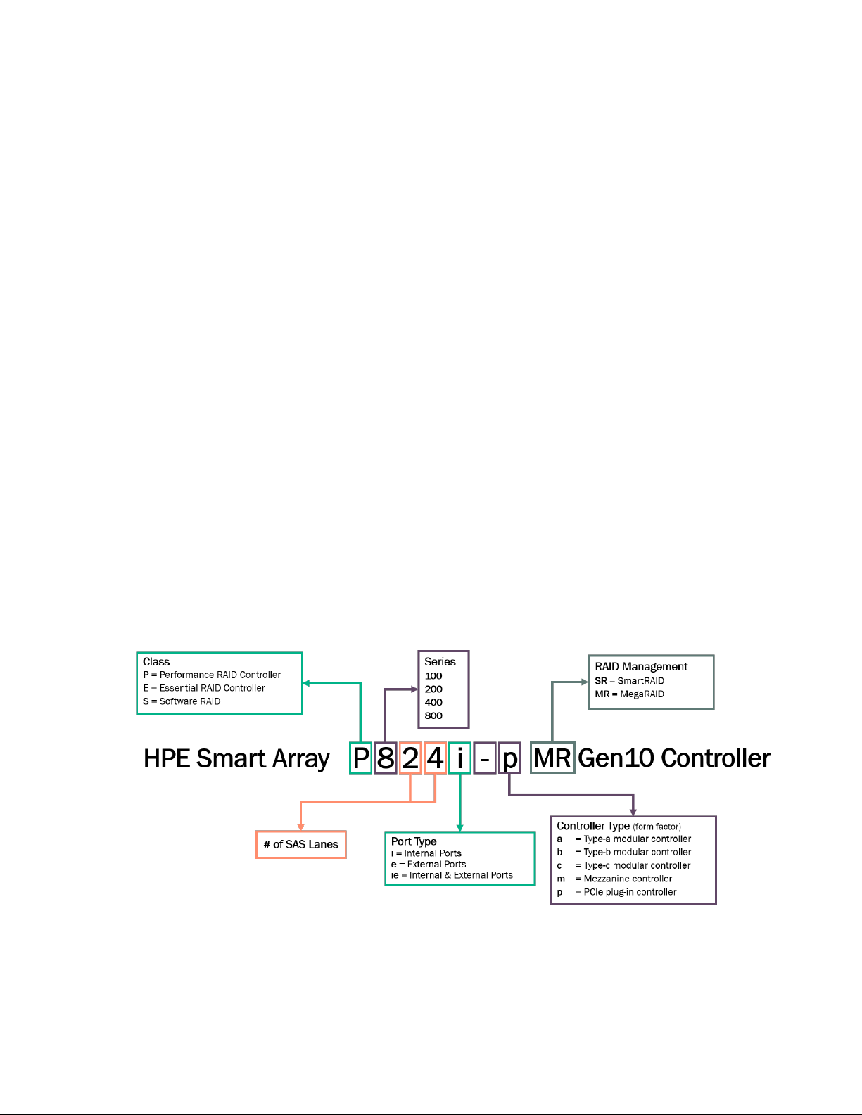
The HPE Smart Array controllers are named according to the features of the controller, as shown below.
HPE Smart Array P824i-p MR Gen10 5
Page 6

Features
Controller supported features
This section lists the features supported by the P824i-p Smart Array MR controller. For additional
information about the features, see MR Storage Administrator User Guide at the Hewlett Packard
Enterprise website
Operating environments
The following operating environments are supported:
• Windows
• Linux
• VMware ESXI
• Legacy Boot mode
• UEFI Boot mode
RAID technologies
The following RAID technologies are supported:
http://www.hpe.com/support/MRSA.
• RAID levels 0, 1, 5, 6, 10, 50, 60
• Max logical drives - 64
• Max physical drives - 240
• Max physical per logical drives - 64
• Mixed mode (RAID and JBOD)
• Making unconfigured good and making JBOD
• Patrol read
• Read load balancing
• Parity groups
• Fast and full initialization
• Regenerative writes
• Backed out writes
• Full-stripe writes
• Dedicated spare
• Global spare
• Drive rebuilds
• Foreign configuration import
6 Features
Page 7

Transformation
The following transformation features are supported:
• Expand Array
• Transportable controller
• Extend logical drive
• Migrate RAID level
• Transformation priority
Drive technology
The following drive technology features are supported:
• HPE SmartDrive LED
• Consistency check
• Discarding pinned cache
• Online drive firmware update
Security
The following security features are supported:
• Drive erase
• Sanitize erase
Reliability
The following reliability features are supported:
• Recovery ROM
• Cache Error Checking and Correction
• Thermal monitoring
Performance
The following performance features are supported:
• SAS storage link speed
• FastPath (SSD accelerator)
• CacheCade
• Read policy (read ahead)
• Write policy
• I/O policy
Features 7
Page 8
• Drive caching
• Stripe size selection
RAID technologies
Selecting the right RAID type for your IT infrastructure
The RAID setting that you select is based upon the following:
• The number of parity groups that you have
• The fault tolerance required
• The write performance required
• The amount of usable capacity that you have
Configuring the RAID fault tolerance
If your IT environment requires a high level of fault tolerance, select a RAID level that is optimized for fault
tolerance.
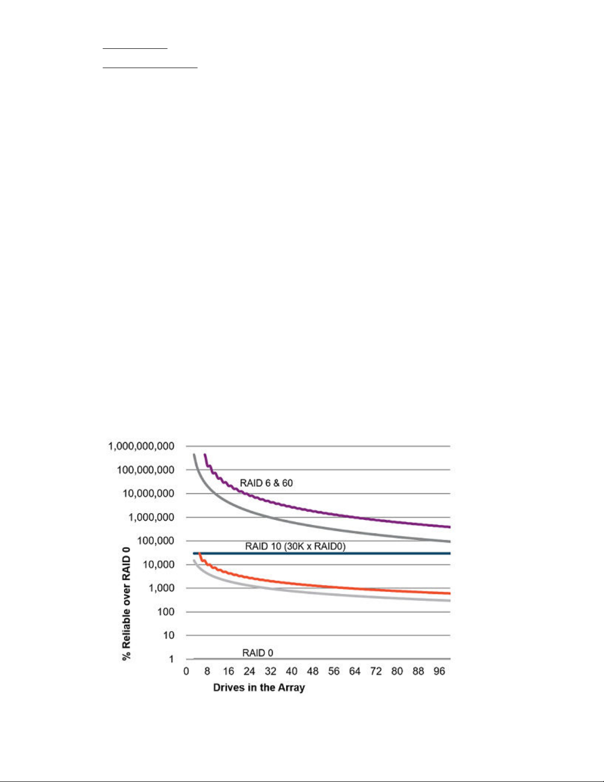
This chart shows the relationship between the RAID level fault tolerance and the size of the storage array.
The chart includes RAID 0, 5, 50, 10, 6, and 60. It also shows the percent reliability in increments
between 1 and one billion and the storage array drive increments between 0 and 96.
This chart assumes that two parity groups are used for RAID 50 and RAID 60.
This chart shows that:
• RAID 10 is 30,000 times more reliable than RAID 0.
• The fault tolerance of RAID 5, 50, 6, and 60 decreases as the array size increases.
8 Features
Page 9
Configuring the RAID write performance
If your environment requires high write performance, select a RAID type that is optimized for write
performance
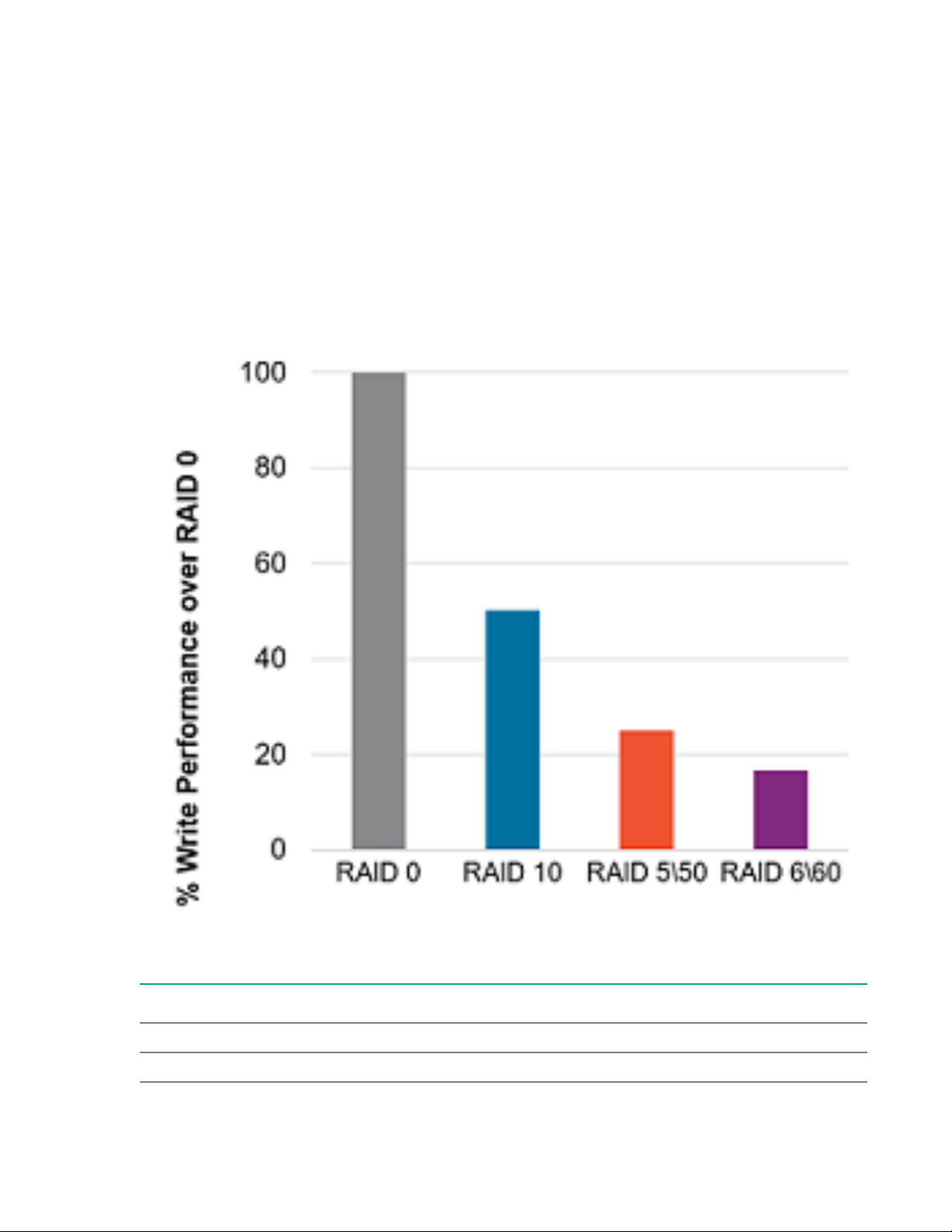
The chart below shows how RAID 10, 5, 50, 6, and 60 compare to the percent write performance of RAID
0.
The data in the chart assumes that drives are limited and that drive write performance is the same as
drive read performance.
Consider the following points:
• Write performance decreases as fault tolerance improves due to extra I/O.
• Read performance is generally the same for all RAID levels except for smaller RAID 5\6 arrays.
The table below shows the Disk I/O for every host write:
RAID type Disk I/O for every host write
RAID 0 1
RAID 10 2
Table Continued
Features 9
Page 10

RAID type Disk I/O for every host write
RAID 5 4
RAID 6 6
Configuring the RAID usable capacity
If your environment requires a high usable capacity, select a RAID type that is optimized for usable
capacity. The chart in this section demonstrates the relationship between the number of drives in the
array and the percent usable capacity over the capacity for RAID 0.
Consider the following points when selecting the RAID type:
• Usable capacity decreases as fault tolerance improves due to an increase in parity data.
• The usable capacity for RAID 10 remains flat with larger arrays.
• The usable capacity for RAID 5, 50, 6, and 60 increases with larger arrays.
• RAID 50 and RAID 60 assumes two parity groups.
Note the minimum drive requirements for the RAID types, as shown in the table below.
RAID type Minimum number of drives
RAID 0 1
RAID 10 2
RAID 5 3
RAID 6 4
RAID 50 6
RAID 60 8
10 Features
Page 11
Configuring the storage solution
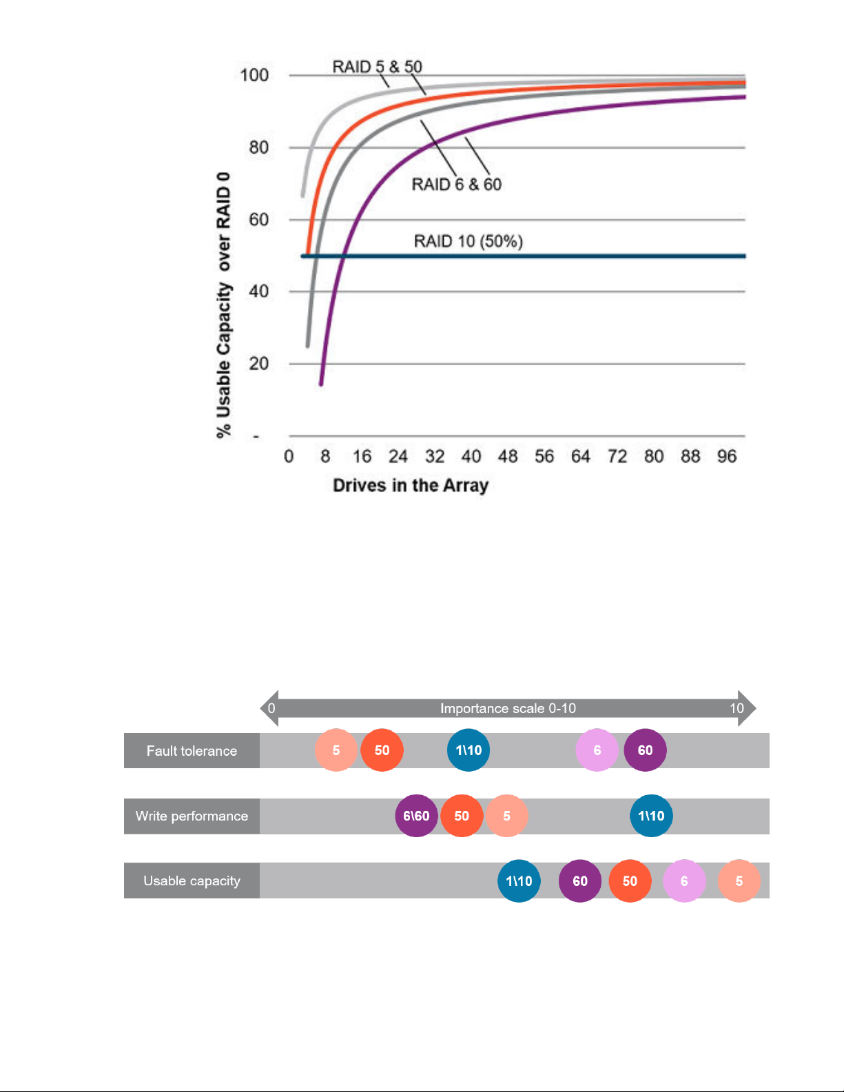
The chart in this section shows the relevance of the RAID type to the requirements of your environment.
Depending on your requirements, you should optimize the RAID types as follows:
• RAID 6/60: Optimize for fault tolerance and usable capacity.
• RAID 1/10: Optimize for write performance.
• RAID 5/50: Optimize for usable capacity.
Features 11
Page 12

Mixed mode (RAID and JBOD simultaneously)
Mixed mode allows for any drive to be a member of a logical drive (logical volume or RAID volume),
unconfigured and hidden from the operating system, or in a JBOD drive state which exposes the drive to
the host operating system as a physical drive.
Make Unconfigured Good and Make JBOD
When you power down a controller and insert a new drive and if the inserted drive does not contain valid
DDF metadata, the drive status is listed as JBOD (Just a Bunch of Drives) when you power on the system
again. When you power down a controller and insert a new drive and if the drive contains valid DDF
metadata, its drive state is Unconfigured Good. A new drive in the JBOD drive state is exposed to the
host operating system as a standalone drive. You cannot use JBOD drives to create a RAID
configuration, because they do not have valid DDF records. Therefore, you must convert JBOD drives to
unconfigured good drives.
If the controller supports JBOD drives, the MR Storage Administrator includes options for converting
JBOD drives to an unconfigured good drive, or an unconfigured good drive to a JBOD drive.
Patrol read
A patrol read periodically verifies all sectors of the drives connected to a controller, including the system
reserved area in the RAID configured drives. You can run a patrol read for all RAID levels and for all
spare drives. A patrol read is initiated only when the controller is idle for a defined period and has no
other background activities. You can set the patrol read properties and start the patrol read operation, or
you can start the patrol read without changing the properties.
Access the patrol rate by selecting Set Adjustable Task Rate under the More Actions menu then locating
it under the Priority Percentage column. Enter a number from 1 to 100. The higher the number, the faster
the patrol read will occur (and the system I/O rate might be slower as a result).
Striping
RAID 0
A RAID 0 configuration provides data striping, but there is no protection against data loss when a drive
fails. However, it is useful for rapid storage of large amounts of noncritical data (for printing or image
editing, for example) or when cost is the most important consideration. The minimum number of drives
required is one.
The maximum number of drives supported for RAID 0 is 32.
12 Features
Page 13
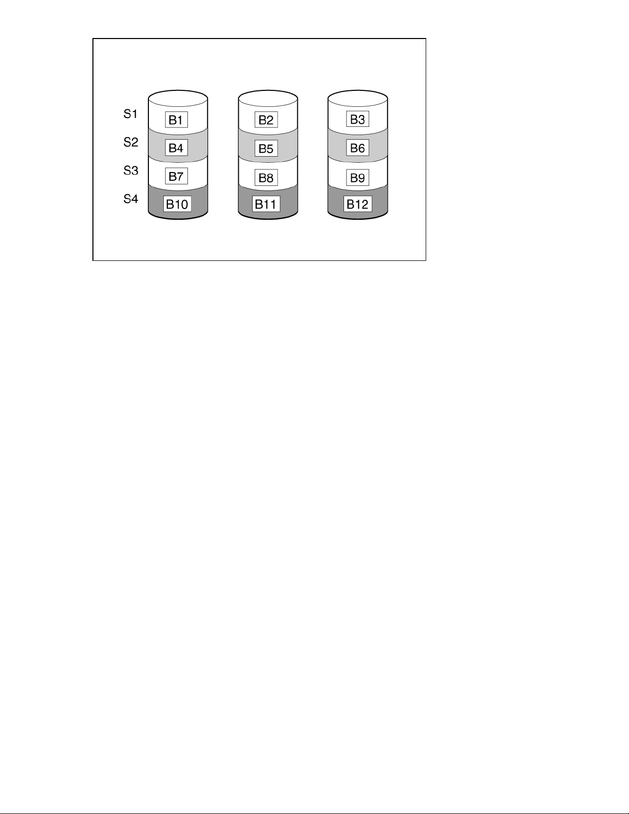
This method has the following benefits:
• Useful when performance and low cost are more important than data protection.
• Has the highest write performance of all RAID methods.
• Has the lowest cost per unit of stored data of all RAID methods.
• All drive capacity is used to store data (none allocated for fault tolerance).
Mirroring
RAID 1 and RAID 1+0 (RAID 10)
In RAID 1 and RAID 1+0 (RAID 10) configurations, data is duplicated to a second drive. The usable
capacity is C x (n / 2) where C is the drive capacity with n drives in the array. A minimum of two drives is
required.
When the array contains only two physical drives, the fault-tolerance method is known as RAID 1.
The maximum number of drives supported for RAID 1 is 32.
Features 13
Page 14
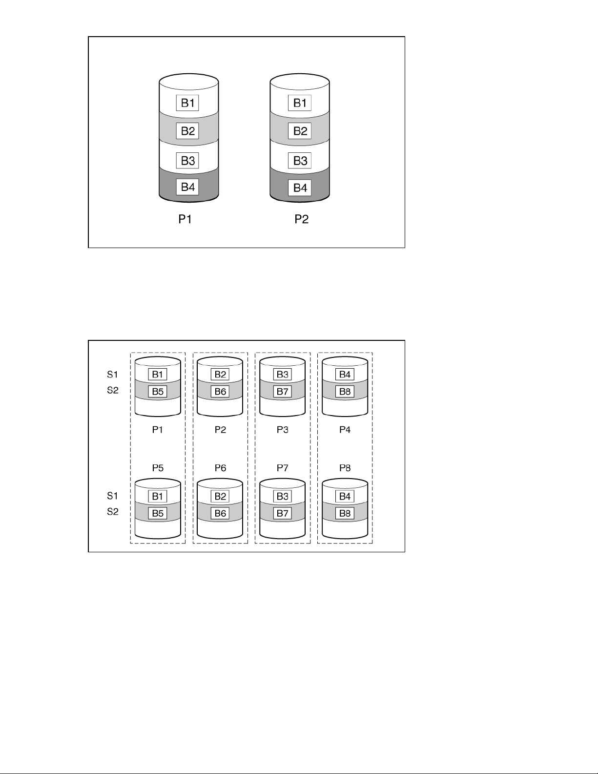
When the array has more than two physical drives, drives are mirrored in pairs, and the fault-tolerance
method is known as RAID 1+0 or RAID 10. If a physical drive fails, the remaining drive in the mirrored pair
can still provide all the necessary data. Several drives in the array can fail without incurring data loss, as
long as no two failed drives belong to the same mirrored pair. The total drive count must increment by 2
drives. A minimum of four drives is required.
The maximum number of drives supported for RAID 10 is 32.
This method has the following benefits:
• It is useful when high performance and data protection are more important than usable capacity.
• This method has the highest write performance of any fault-tolerant configuration.
• No data is lost when a drive fails, as long as no failed drive is mirrored to another failed drive.
• Up to half of the physical drives in the array can fail.
14 Features
Page 15

Read load balancing
In each mirrored pair or trio, Smart Array balances read requests between drives based upon individual
drive load.
This method has the benefit of enabling higher read performance and lower read latency.
Parity
RAID 5
RAID 5 protects data using parity (denoted by Px,y in the figure). Parity data is calculated by summing
(XOR) the data from each drive within the stripe. The strips of parity data are distributed evenly over
every physical drive within the logical drive. When a physical drive fails, data that was on the failed drive
can be recovered from the remaining parity data and user data on the other drives in the array. The
usable capacity is C x (n - 1) where C is the drive capacity with n drives in the array. A minimum of three
drives is required.
The maximum number of drives supported for RAID 5 is 32.
This method has the following benefits:
• It is useful when usable capacity, write performance, and data protection are equally important.
• It has the highest usable capacity of any fault-tolerant configuration.
• Data is not lost if one physical drive fails.
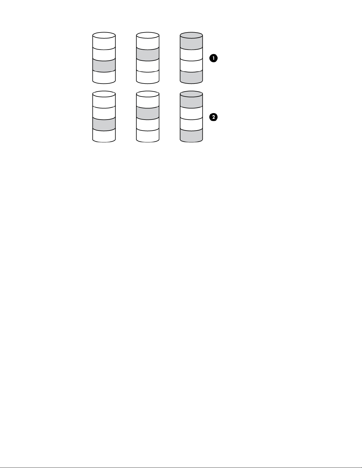
RAID 50
RAID 50 is a nested RAID method in which the constituent drives are organized into several identical
RAID 5 logical drive sets (parity groups). The smallest possible RAID 50 configuration has six drives
organized into two parity groups of three drives each.
Features 15
Page 16
RAID 6
For any given number of drives, data loss is least likely to occur when the drives are arranged into the
configuration that has the largest possible number of parity groups. For example, four parity groups of
three drives are more secure than three parity groups of four drives. However, less data can be stored on
the array with the larger number of parity groups.
All data is lost if a second drive fails in the same parity group before data from the first failed drive has
finished rebuilding. A greater percentage of array capacity is used to store redundant or parity data than
with non-nested RAID methods (RAID 5, for example). A minimum of six drives is required.
The maximum number of drives supported for RAID 50 is 256.
This method has the following benefits:
• Higher performance than for RAID 5, especially during writes.
• Better fault tolerance than either RAID 0 or RAID 5.
• Up to n physical drives can fail (where n is the number of parity groups) without loss of data, as long
as the failed drives are in different parity groups.
RAID 6 protects data using double parity. With RAID 6, two different sets of parity data are used (denoted
by Px,y and Qx,y in the figure), allowing data to still be preserved if two drives fail. Each set of parity data
uses a capacity equivalent to that of one of the constituent drives. The usable capacity is C x (n - 2)
where C is the drive capacity with n drives in the array.
A minimum of 4 drives is required.
The maximum number of drives supported for RAID 6 is 32.
16 Features
Page 17
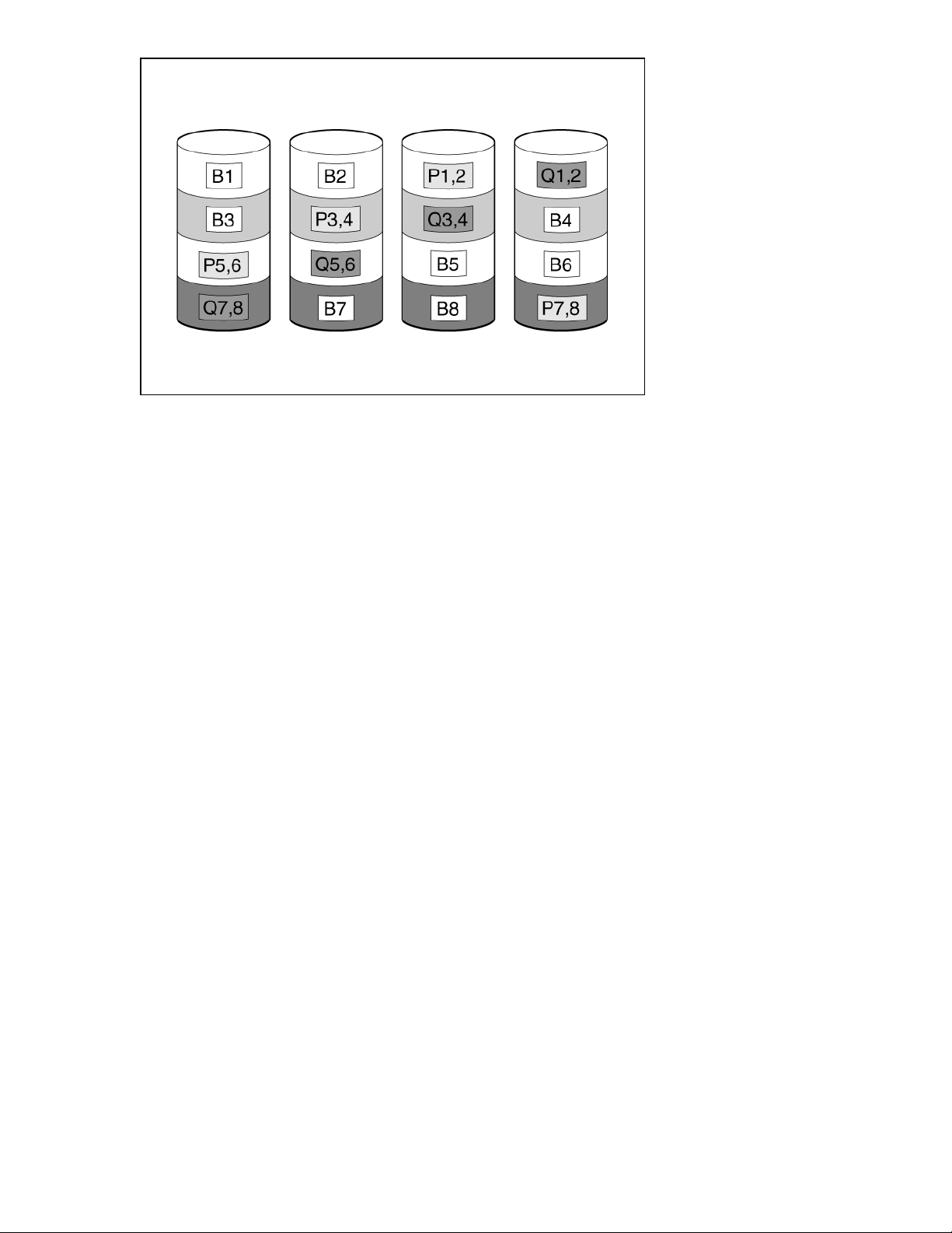
This method is most useful when data loss is unacceptable but cost is also an important factor. The
probability that data loss will occur when an array is configured with RAID 6 (Advanced Data Guarding
(ADG)) is less than it would be if it were configured with RAID 5.
This method has the following benefits:
• It is useful when data protection and usable capacity are more important than write performance.
• It allows any two drives to fail without loss of data.
RAID 60
RAID 60 is a nested RAID method in which the constituent drives are organized into several identical
RAID 6 logical drive sets (parity groups). The smallest possible RAID 60 configuration has eight drives
organized into two parity groups of four drives each.
For any given number of hard drives, data loss is least likely to occur when the drives are arranged into
the configuration that has the largest possible number of parity groups. For example, five parity groups of
four drives are more secure than four parity groups of five drives. However, less data can be stored on
the array with the larger number of parity groups.
The number of physical drives must be exactly divisible by the number of parity groups. Therefore, the
number of parity groups that you can specify is restricted by the number of physical drives. The maximum
number of parity groups possible for a particular number of physical drives is the total number of drives
divided by the minimum number of drives necessary for that RAID level (three for RAID 50, 4 for RAID
60).
A minimum of 8 drives is required.
The maximum number of drives supported for RAID 60 is 256.
All data is lost if a third drive in a parity group fails before one of the other failed drives in the parity group
has finished rebuilding. A greater percentage of array capacity is used to store redundant or parity data
than with non-nested RAID methods.
This method has the following benefits:
Features 17
Page 18

• Higher performance than for RAID 6, especially during writes.
• Better fault tolerance than RAID 0, 5, 50, or 6.
• Up to 2n physical drives can fail (where n is the number of parity groups) without loss of data, as long
as no more than two failed drives are in the same parity group.
Parity groups
When you create a RAID 50 or RAID 60 configuration, you must also set the number of parity groups.
You can use any integer value greater than 1 for this setting, with the restriction that the total number of
physical drives in the array must be exactly divisible by the number of parity groups.
The maximum number of parity groups possible for a particular number of physical drives is the total
number of drives divided by the minimum number of drives necessary for that RAID level (three for RAID
50, four for RAID 60).
This feature has the following benefits:
• It supports RAID 50 and RAID 60.
• A higher number of parity groups increases fault tolerance.
Initialization state
Initialize a logical drive after you configure it. When you initialize the logical drive, you prepare the storage
medium for use.
CAUTION: All data on the logical drive is lost when you initialize it. Before you start this operation,
back up any data that you want to keep.
Fast initialization
During fast initialization, the firmware quickly overwrites the first and last 8 MB regions of the new logical
drive, clearing any boot records or partition information, and then completes the initialization in the
background. Monitor the progress of the initialization process using the progress indicator.
RAID levels that use parity (RAID 5, RAID 6, RAID 50, and RAID 60) require that the parity blocks be
initialized to valid values. Valid parity data is required to enable enhanced data protection through
background controller surface scan analysis and higher write performance (backed out write). After parity
initialization is complete, writes to a RAID 5 or RAID 6 logical drive are typically faster because the
controller does not read the entire stripe (regenerative write) to update the parity data. This feature
initializes parity blocks in the background while the logical drive is available for access by the operating
system. Parity initialization takes several hours to complete. The time it takes depends on the size of the
logical drive and the load on the controller. While the controller initializes the parity data in the
background, the logical drive has full fault tolerance.
This method has the benefit of allowing you to start writing data to the logical drive immediately.
Access the background initialization (BGI) rate by selecting Set Adjustable Task Rate under the More
Actions menu than locating it under the Priority Percentage column. Enter a number from 1 to 100. The
higher the number, the faster the initialization will occur (and the system I/O rate might be slower as a
result).
If you use RAID 5, you must have a minimum of five drives for a background initialization to start. If you
use RAID 6, you must have at least seven drives for a background initialization to start.
18 Features
Page 19

Full initialization
During full initialization, a complete initialization is done on the new configuration. You cannot write data to
the new logical drive until the initialization is complete. This process can take a long time if the drives are
large. This initialization overwrites all blocks and destroys all data on the logical drive.
Monitor the progress of the initialization process using the progress indicator.
No initialization
If you select this option, the new configuration is not initialized, and the existing data on the drives is not
overwritten. You can initialize the logical drive at a later time.
Regenerative writes
Logical drives can be created with background parity initialization so that they are available almost
instantly. During this temporary parity initialization process, writes to the logical drive are performed using
regenerative writes or full stripe writes. Any time a member drive within an array is failed, all writes that
map to the failed drive are regenerative. A regenerative write is much slower because it must read from
nearly all of the drives in the array to calculate new parity data. The write penalty for a regenerative write
is n + 1 drive operations where n is the total number of drives in the array. As you can see, the write
penalty is greater (slower write performance) with larger arrays.
This method has the following benefits:
• It allows the logical drive to be accessible before parity initialization completes
• It allows the logical drive to be accessible when degraded
Backed-out writes
After parity initialization is complete, random writes to a RAID 5, 50, 6, or 60 can use a faster backed-out
write operation. A backed-out write uses the existing parity to calculate the new parity data. As a result,
the write penalty for RAID 5 and RAID 50 is always four drive operations, and the write penalty for a RAID
6 and RAID 60 is always six drive operations. As you can see, the write penalty is not influenced by the
number of drives in the array.
Backed-out writes is also known as "read-modify-write."
This method has the benefit of faster RAID, 5, 50, 6, or 60 random writes.
Full-stripe writes
When writes to the logical drive are sequential or when multiple random writes that accumulate in the
flash-backed write cache are found to be sequential, a full-stripe write operation can be performed. A fullstripe write allows the controller to calculate new parity using new data being written to the drives. There
is almost no write penalty because the controller does not need to read old data from the drives to
calculate the new parity. As the size of the array grows larger, the write penalty is reduced by the ratio of
p / n where p is the number of parity drives and n is the total number of drives in the array.
This method has the benefit of faster RAID 5, 6, or 60 sequential writes.
Spare drives
Dedicated spare
A dedicated spare is a spare drive that is dedicated to one array.
It supports any fault tolerant logical drive such as RAID 1, 10, 5, 6, 50, 60, and CacheCade SSD volumes.
The dedicated spare drive activates any time a drive within the array fails.
Features 19
Page 20

Global spare
A global spare drive replaces a failed drive in any array, as long as:
• The drive type is the same.
• The capacity of the global spare drives is equal to or larger than the capacity of the failed drive.
A global spare drive activates any time a drive fails within a fault tolerant logical drive or CacheCade SSD
volume. For RAID 0 logical drives, the global spare will active when a member drive reports a predictive
failure.
Drive rebuild
If a drive, which is configured as RAID 1, 5, 6, 10, 50, or 60 fails, the firmware automatically rebuilds the
data on a spare or replacement drive to prevent data loss. The rebuild is a fully automatic process.
Monitor the progress of drive rebuilds in the Background Processes in Progress window.
Access the drive rebuild rate by selecting Set Adjustable Task Rate under the More Actions menu then
locating it under the Priority Percentage column. Enter a number from 1 to 100. The higher the number,
the faster the rebuild will occur (and the system I/O rate might be slower as a result).
Foreign configuration import
A foreign configuration import is a RAID configuration that exists on a replacement set of drives that you
install in a computer system. You can use the MR Storage Administrator to import the foreign
configuration to the controller or clear the foreign configuration so that you can create a configuration
using these drives.
Transformation
Array transformations
Expand array
Increase the capacity of an existing array by adding currently existing unassigned drives to it. Any drive
that you want to add must meet the following criteria:
• It must be an unassigned drive.
• It must be of the same type as existing drives in the array (for example, SAS HDD, SAS SSD, SATA
HDD, or SATA HDD).
• It must have a capacity no less than the capacity of the smallest drive in the array.
This operation uses the Modify Array option in the HPE MR Storage Administrator user interface. This
feature is supported when there is a single logical drive configured in the array.
Logical drive transformations
Transportable controller
The controller firmware supports a transportable battery-backed cache memory to recover the data from a
faulty server. This transportable controller recovers from a faulty server by moving the entire controller to
a new replacement server.
In this design, the controller firmware assumes that the new server has the same configuration. That is,
the configuration includes the same server generation and family, and logical drives are migrated to the
new target server to facilitate cache flush when the data is restored.
20 Features
Page 21

Extend logical drive
The logical drive extension feature allows the capacity of a logical drive to be expanded by using unused
space on existing disks, without requiring a reboot.
Increase the capacity of an existing logical drive by specifying a new size. Once the task is performed,
use operating system partitioning software to take advantage of the extended space available.
Enable this feature in the HPE MR Storage Administrator user interface using the Expand option within
the Logical Drive Actions menu.
Migrate RAID level
RAID level transformation is the process of converting one RAID configuration to another. You can
perform RAID level transformation at the array level.
The RAID level transformation feature allows you to change the current level of fault tolerance (RAID
type) for your logical drive. When the fault tolerance changes, you may have more or less unused space,
depending on the fault tolerance with which you started.
The following table describes the valid RAID level transformation matrix.
Initial RAID level Migrated RAID level
RAID 0 RAID 1
RAID 0 RAID 5
RAID 0 RAID 6
RAID 1 RAID 0
RAID 1 RAID 5
RAID 1 RAID 6
RAID 5 RAID 0
RAID 5 RAID 6
RAID 6 RAID 0
RAID 6 RAID 5
Transformation priority
As the transformation priority level increases, the rate at which requests from the operating system are
processed decreases. Transformation refers to array expansions, logical drive extensions, logical drive
migrations, and array shrink and move operations.
Access the transformation priority rate by selecting Set Adjustable Task Rate under the More Actions
menu then locating it under the Priority Percentage column. The default value is 30%. Enter a number
from 0 to 100 to control the rate at which transformation of a logical drive occurs. The higher the number,
the faster the transformation occurs (and the system I/O rate might be slower as a result).
Drive technology
HPE SmartDrive LED
HPE SmartDrives are the latest Hewlett Packard Enterprise drive technology. Identify a SmartDrive by its
carrier, shown in the following illustration.
When a drive is configured as a part of an array and connected to a powered-up controller, the drive
LEDs indicate the condition of the drive.
Features 21
Page 22
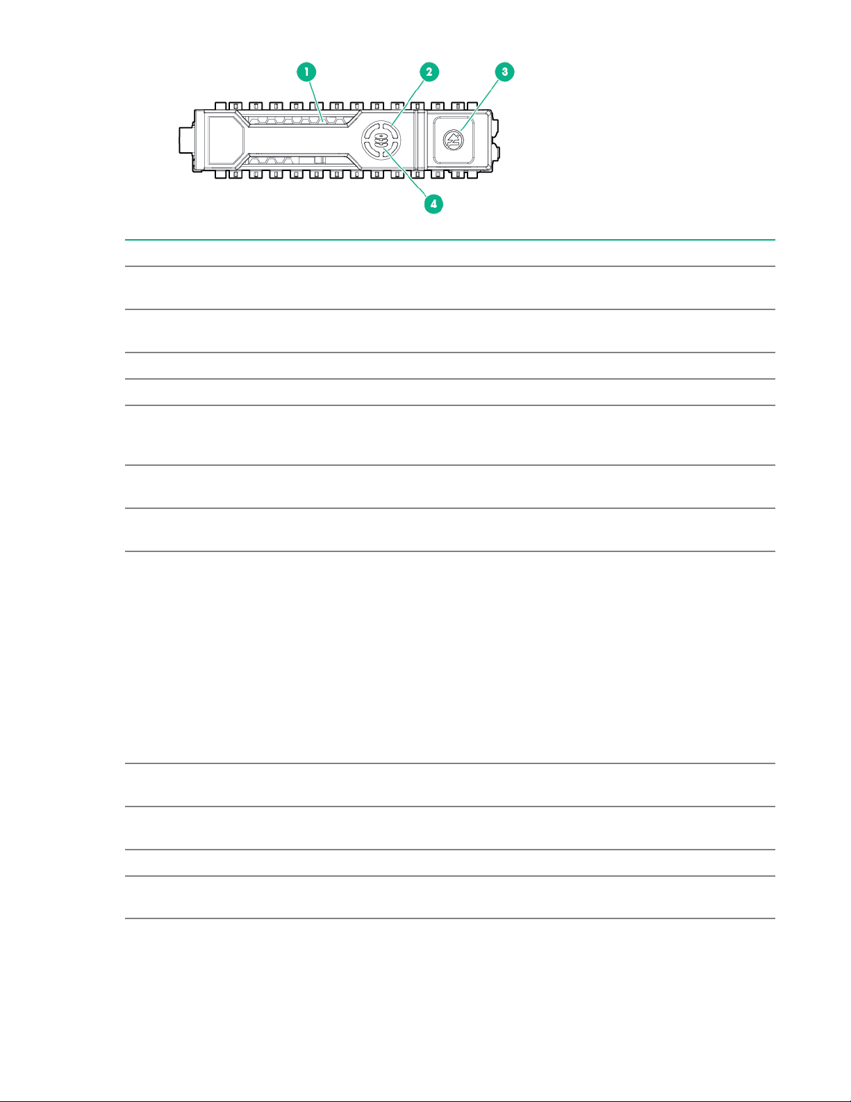
Item LED Status Definition
1 Locate
1
Solid blue The drive is being identified by a host
application.
Flashing blue The drive carrier firmware is being updated
or requires an update.
2 Activity ring Rotating green Drive activity
Off No drive activity
3 Do not remove Solid white Do not remove the drive. Removing the
drive causes one or more of the logical
drives to fail.
Off Removing the drive does not cause a logical
drive to fail.
4 Drive status Solid green The drive is a member of one or more
logical drives.
Flashing green The drive is doing one of the following:
• Rebuilding
• Performing a RAID migration
• Performing a capacity expansion
Flashing amber/green The drive is a member of one or more
Flashing amber The drive is not configured and predicts the
Solid amber The drive has failed.
Off The drive is not configured by a RAID
1
The blue Locate LED is behind the release lever and is visible when illuminated.
22 Features
• Performing a logical drive extension
• Erasing
• Spare drive activation
logical drives and predicts the drive will fail.
drive will fail.
controller or is a spare drive.
Page 23

Consistency check
A consistency check operation verifies the correctness of the data in logical drives that use RAID levels 1,
5, 6, 10, 50, and 60. For example, in a system with parity, checking consistency means calculating the
data on one drive and comparing the results to the contents of the parity drive.
Periodically run a consistency check on fault-tolerant logical drives. Because RAID 0 does not provide
data redundancy, you cannot run a consistency check on RAID 0 logical drives.
To run a consistency check, you must first set the consistency check properties, and then you can either:
• Schedule a consistency check to be run at an interval that you define.
• Start the consistency check operation immediately.
The consistency check priority value ranges from 1 to 100.
You can use the following modes for the consistency check:
• Concurrent - Run consistency check concurrently on all logical drives.
• Sequential - Run consistency check on one logical drive at a time.
• Disable - Disables consistency check.
Access the consistency check rate by selecting Set Adjustable Task Rate under the More Actions menu
then locating it under the Priority Percentage column. Enter a number from 1 to 100. The higher the
number, the faster the consistency check is performed (and the system I/O rate might be slower as a
result).
Online drive firmware update
The latest generation HPE Smart Array controllers support online drive flashing, which saves time when
updating disk drive firmware. Instead of taking the hard disk drive (HDD) offline before loading a new
firmware image, you can download an updated HDD firmware image to the HPE Smart Array controller
and update all of the HDDs the next time you reboot the server.
Discarding pinned cache
If the controller loses access to one or more logical drives, the controller preserves the data from the
logical drive. This preserved cache is called Pinned Cache. This cache is preserved until you import the
logical drive or discard the cache.
As long as there is pinned cache, you cannot perform certain operations on the logical drive.
IMPORTANT: If there are any foreign configurations, import the foreign configuration before you
discard the pinned cache. Otherwise, you might lose data that belongs to the foreign configuration.
Dynamic sector repair
Disk drive media can develop defects caused by variances in the drive mechanisms under normal
operating conditions. To protect data from media defects, HPE built a dynamic sector repair feature into
HPE Smart Array controllers.
Patrol read:
• scans drives and repairs media defects
• detects and repairs media defects when accessing a bad sector during busy periods
Features 23
Page 24

Security
Drive erase
Erase data on drives by using the Drive Erase option. The erase operation consists of a series of write
operations to a drive that overwrite every user-accessible sector of the drive with specified patterns. The
erase operation can be repeated in multiple passes using different data patterns for enhanced security.
The erase operation is performed as a background task.
After the drive erase operation has started, you can stop the erase using the Actions menu.
Simple
A Simple erase writes a pattern to the logical drive in a single pass.
Normal
A normal erase operation is a three-pass operation that first overwrites the drive contents with random
values then overwrites it twice with patterns.
Thorough
A thorough drive erase operation repeats the Normal drive erase operation three times.
Sanitize erase
The sanitize erase feature lets you erase the data residing on a drive using the Sanitize feature. Sanitize
is similar to the Drive Erase feature, except that sanitize is performed by the drive firmware and drive
erase is performed by the controller firmware.
The sanitize option is an industry standard SCSI feature. It uses industry standard Sanitize SCSI Block
command. The sanitize operation is constantly monitored by the controller firmware, and the drive
sanitization progress events are reported to you through Background Operations Support.
To Sanitize a drive, you must make sure that:
• The selected drive is in an Unconfigured Good state.
• The selected drive is not a JBOD drive.
• The selected drive is not part of any array, dedicated spare drive, or global spare drive.
Sanitize operation is enabled only when no other operation is in progress on the selected drive. When the
sanitize operation is in progress, you cannot perform any other operation on the drive that is being
sanitized.
Depending on the drives you have selected for sanitization (SSDs or HDDs), the following options are
available:
• Overwrite - HDD only; This option writes a data pattern on the drive one or more times.
• Block erase - SSD only; This option sets the physical blocks on the drive to a vendor-specific value.
• Allow Unrestricted Sanitize Exit - If the Sanitize operation fails, the system tries to bring the drive out of
the failure mode. If this option is slected, and if the system succeeds in bringing the drive out of the
failure mode, the drive is returned to an Unconfigured Good state. If this option is not selected, and if
the Sanitize operation fails, the system places the drive in an Unconfigured Bad state.
24 Features
Page 25

Reliability
Recovery ROM
HPE Smart Array controllers store a redundant copy of the controller firmware image to protect against
data corruption. If the active firmware image becomes corrupt, HPE Smart Array controllers use the
redundant firmware image and continue operating. The recovery ROM provides protection against power
outages during firmware flashing.
Cache Error Checking and Correction (ECC)
Error checking and correction (ECC) DRAM technology protects the data while it is in cache. The ECC
scheme generates 8 bits of check data for every 64 bits of regular data transferred. The Smart Array
memory controller uses this information to detect and correct data errors originating inside the DRAM chip
or across the memory bus.
Thermal monitoring
Smart Array monitors the temperature of each drive in the server. iLO periodically collects these drive
temperatures from Smart Array to control the fan speed. The fan speed is optimized so that each drive is
maintained below its maximum continuous operating temperature regardless of the workload.
This method has the benefit of saving cost by allowing the fans to run at an optimal setting while ensuring
that drives do not overheat.
Performance
SAS storage link speed
The Manage SAS Storage Link Speed feature allows you to change the link speed between the controller
and an expander or between the controller and a drive that is directly connected to the controller. All phys
(physical links) in a SAS port can have different link speeds or can have the same link speed.
If phys in a SAS port have different link speed settings and if a phy is connected to a drive or an
expander, the firmware overrides the link speed setting you have selected and instead uses the common
maximum link speed among all the phys.
The default setting for all phys is Max, and options include 3 GB/s, 6 GB/s, and 12 GB/s.
HPE Smart Array MR FastPath
The HPE Smart Array MR FastPath feature is an intelligent I/O passthrough mechanism for Solid State
Drive (SSD) arrays. This advanced software is an optimized version of controller technology that can
dramatically boost storage subsystem and overall application performance, especially for applications that
demonstrate high random read/write operation workloads.
FastPath is enabled for a logical drive when the logical drive is created with properties Direct IO, Write
Through, and No Read Ahead.
The logical drive must be in an optimal state for FastPath to be enabled.
FastPath allows the following IO scenarios:
• Read IOs to all RAID levels when IO size is less than or equal to the strip size.
• Write IOs to RAID 0 when IO size is less than or equal to the strip size.
• All IOs targeted to a single drive RAID 0.
Features 25
Page 26

Write IOs to RAID 1, 5, and 6 are not allowed through FastPath.
HPE Smart Array MR CacheCade
The CacheCade read and write feature eliminates the need for manually configured hybrid arrays by
intelligently and dynamically managing frequently accessed data and copying it from HDD volumes to a
higher performance layer of SSD cache. Copying the most accessed data (hot spot) to flash cache
relieves the primary HDD array from time-consuming transactions, which allows for more efficient hard
disk operation, reduced latency, and accelerated read and write speeds. With the addition of write caching
support, read/write-intensive workloads such as Exchange server, high performance computing (HPC)
applications, Web 2.0, and other IO-intensive OLTP database system workloads experience dramatic
performance improvements.
If you enable SSD caching on a logical drive, that logical drive becomes associated with an existing or
with a future CacheCade - SSD Caching logical drive.
NOTE: You can create only one CacheCade-SSD Caching logical drive as the full capacity of the logical
drive is used for the creation of CacheCade-SSD Caching logical drive.
This method has the following benefits:
• Accelerates application performance
• Provides lower latency for transactions in applications
Cache
Read policy
The read policy options for the logical drive are:
• No Read Ahead - In no read ahead mode, read ahead capability is disabled. This setting is the default
option.
• Read ahead - Read ahead capability allows the controller to read sequentially ahead of requested
data and to store the additional data in cache memory, anticipating that the data will be needed soon.
This process speeds up reads for sequential data, but there is little improvement occurs when
accessing random data.
Write policy
The write policy options for the logical drive are:
• Write Through (SSD only) - In this mode, the controller sends a data transfer completion signal to the
host when the drive subsystem has received all the data in a transaction. This mode may result in
slower performance as it does not use the controller cache.
• Write Back - In this mode, the controller sends a data transfer completion signal to the host when the
controller cache has received all the data in a transaction. This option provides a good balance
between data protection and performance as the controller switches between Write back and write
through depending on the controller status.
• Always Write Back - In this mode, the controller sends a data transfer completion signal to the host
when the controller cache receives all the data in a transaction. If you select the Always Write Back
policy and the energy pack is absent, the firmware is forced to use the Write Back policy.
26 Features
Page 27

This controller now supports two power options to enable the controller cache features. Collectively, these
two options are known as the "energy pack" and include the following:
• HPE Smart Storage Battery
• HPE Smart Storage Hybrid Capacitor
For more information about these options, see "Energy pack options."
NOTE: Write back caching is enabled when the energy pack is installed and charged. Write Through is
enabled when the energy pack is not installed, if the charge is low, or if it fails during a relearn cycle. To
monitor the status of the energy pack, use iLO.
Since the interface does not display the cache policy used during the creation of the logical drive, you can
identify the policy by:
• viewing the energy pack charge status in iLO and the write cache status
• view cache policy information in the event log
• temporarily disabling the cache, which displays the original cache setting
I/O policy
The I/O policy applies to reads on a specific logical drive. It does not affect the read ahead cache. The I/O
options for the logical drive are:
• Direct IO - In direct I/O mode, reads are not buffered in cache memory. Data is transferred to the
cache and the host concurrently. If the same data block is read again, it comes from cache memory.
This option is the default setting.
• Cached IO - In cached IO mode, all reads are buffered in cache memory. This option is suited for once
write and multiple read workloads.
Drive caching
The drive caching options for the logical drive are:
• Unchanged - Leave the current drive cache policy as is.
• Enabled - Enable the drive cache
• Disabled -- Disabled the drive cache
Stripe size selection
When a logical drive is created, the unit of data that it manipulates is defined as a “strip” (ranging in size
from 64 KiB to 1 MiB). These strips are distributed across the physical drives in the array. A "stripe" is one
set of strips. Striping helps to distribute the I/O workload across multiple physical drives. HPE Smart Array
controllers configure strips, not stripes.
You can calculate the stripe size from:
• Strip size
• Number of physical drives in the logical drive
• RAID level
Features 27
Page 28

The best performance and drive longevity is obtained by aligning and sizing the strip and thus stripe size
to the application I/O request size and alignment. The smaller (<= 64 KiB) the strip size, the longer the
background parity scans and rebuilds take and the more impact to the host I/O during these operations.
However, multiple stripes can be checked or rebuilt concurrently.
28 Features
Page 29
Installation
Installation
Use the topics in this section to install the controller into a server that is already configured or a server
that is not yet configured.
Installing an HPE Smart Array P824i-p MR Gen10 controller in a configured server
Procedure
1. Back up data on the system.
2. Close all applications.
3. Update the server firmware if it is not the latest revision.
4. Do one of the following:
• If the new Smart Array is the new boot device, install the device drivers.
• If the new Smart Array is not the new boot device, go to the next step.
NOTE: If the logical drive is used in a Smart Array SR controller RAID array, you are not able to boot
from that device if you are attached to a Smart Array MR controller.
5. Ensure that users are logged off and all tasks are completed on the server.
6. Power down the server.
CAUTION: In systems that use external data storage, be sure that the server is the first unit to
be powered down and the last to be powered back up. Taking this precaution ensures that the
system does not erroneously mark the drives as failed when the server is powered up.
7. Power down all peripheral devices that are attached to the server.
8. Disconnect the power cord from the power source.
9. Disconnect the power cord from the server.
10. Remove or open the access panel.
WARNING: To reduce the risk of personal injury from hot surfaces, allow the drives and the
internal system components to cool before touching them.
11. Remove the riser.
12. Select an available x8 or larger PCIe expansion slot.
A x8 physical size slot is required, even though the slot width may be electrically x4 or x1. Hewlett
Packard Enterprise recommends using a slot that is electrically x8.
13. Remove the slot cover.
Save the retaining screw, if one is present.
Installation 29
Page 30

14. Slide the Smart Array along the slot alignment guide, if one is present, and then press the board
firmly into the expansion slot so that the contacts on the board edge are seated properly in the slot.
15. Secure the Smart Array in place with the retaining screw. If the slot alignment guide has a latch (near
the rear of the board), close the latch.
16. Connect the controller backup power cable.
17. Connect storage devices to the controller.
For cabling information, see the server user guide.
18. Install the HPE Smart Storage Battery or HPE Smart Storage Hybrid Capacitor.
19. Reinstall the riser.
20. Connect peripheral devices to the server.
21. Connect the power cord to the server.
22. Connect the power cord to the power source.
23. Power up all peripheral devices.
24. Power up the server.
More information
Powering on and selecting boot options in UEFI Boot Mode on page 32
Updating software and firmware on page 58
Array and controller configuration on page 34
Connecting internal storage on page 33
Installing an HPE Smart Array P824i-p MR Gen10 controller in an unconfigured server
For server-specific procedures, see the server user guide.
Procedure
1. Select an available x8 or larger PCIe expansion slot.
A x8 physical size slot is required, even though the slot width may be electrically x4 or x1. Hewlett
Packard Enterprise recommends using a slot that is electrically x8.
2. Remove the slot cover.
Save the retaining screw, if one is present.
3. Slide the Smart Array along the slot alignment guide, if one is present, and then press the board
firmly into the expansion slot so that the contacts on the board edge are seated properly in the slot.
4. Secure the Smart Array in place with the retaining screw. If the slot alignment guide has a latch (near
the rear of the board), close the latch.
5. Install the HPE Smart Storage Battery or HPE Smart Storage Hybrid Capacitor.
6. Connect the controller backup power cable.
For cabling information, see the server user guide.
7. Install physical drives, as needed.
8. Connect drives to the controller.
30 Installation
Page 31

For cabling information, see the server user guide.
9. Power up the server.
If this is the only controller installed in the server, and it is the boot device, you must configure a
logical drive or select the physical drives for JBOD mode using the Smart Array configuration utility in
UEFI System Utilities.
10. Proceed to installing the operating system with the controller driver.
More information
Updating software and firmware on page 58
Connecting storage devices on page 33
Array and controller configuration on page 34
Installing the operating system with the HPE Smart Array MR Gen10 P824i-p controller driver on page
31
Installing the operating system with the HPE Smart Array MR Gen10 P824i-p controller
driver
Prerequisites
Ensure that you have the HPE Smart Array MR Gen10 P824i-p controller driver available. Obtain it by
extracting it from the SPP (http://www.hpe.com/servers/spp) or by downloading it from the Hewlett
Packard Enterprise Support website https://www.support.hpe.com.
Procedure
1. Power on the server.
2. If you are running the server in UEFI Boot Mode, select F9 (System Utilities).
3. (Optional) If running the server in Legacy Boot Mode, set the controller as the boot controller.
4. (Optional) If running the server in Legacy Boot Mode, change the controller boot order.
5. Configure a logical drive or select physical drives for JBOD mode using the Smart Array configuration
utility in UEFI System Utilities.
6. Launch the operating system installation and point to the controller driver when prompted.
7. If the operating system utility does not see the drive, repeat the step to configure the logical drive or
select physical drives for JBOD and retry the installation.
8. After the installation is complete, use MR Storage Administrator, StorCLI, or the SPP to update the
controller firmware if it is not the latest revision.
More information
Creating a logical drive on page 37
Making a JBOD on page 42
Configuring boot controller options
Configuration procedures vary if the server is running in UEFI Boot Mode or Legacy Boot Mode.
Installation 31
Page 32

Selecting a boot mode
Procedure
1. From the System Utilities screen, select System Configuration > Boot Options > Boot Mode, and
press the Enter key.
2. Select a setting and press the Enter key.
• UEFI Mode (default) - Configures the system to boot to a UEFI-compatible operating system.
NOTE: When booting to the UEFI Mode, configure the system to use native UEFI graphic drivers.
• Legacy BIOS Mode - Configures the system to boot to a traditional operating system in Legacy
BIOS compatibility mode.
3. Press the F10 key to save your selection.
4. Reboot the server.
Powering on and selecting boot options in UEFI Boot Mode
On servers operating in UEFI Boot Mode, the boot controller and boot order are set automatically.
1. Press the Power On/Standby button.
2. During the initial boot:
• To modify the server configuration ROM default settings, press the F9 key in the ProLiant POST
screen to enter the UEFI System Utilities screen. By default, the System Utilities menus are in the
English language.
• If you do not need to modify the server configuration and are ready to install the system software,
press the F10 key to access Intelligent Provisioning.
For more information on automatic configuration, see the UEFI documentation on the Hewlett Packard
Enterprise website.
Changing the Legacy BIOS boot order
Prerequisite
Boot Mode is set to Legacy BIOS Mode.
Procedure
1. From the System Utilities screen, select System Configuration > BIOS/Platform Configuration
(RBSU) > Boot Options > Legacy BIOS Boot Order and press Enter.
2. Use the arrow keys to navigate within the boot order list.
3. Press the + key to move an entry higher in the boot list.
4. Press the - key to move an entry lower in the list.
5. Press F10.
32 Installation
Page 33

Connecting storage devices
For more information about supported drive models on specific Gen10 HPE servers, see the QuickSpecs
for the specific server.
Connecting internal storage
Procedure
1. Power down the server.
2. Install drives, if necessary.
Hewlett Packard Enterprise recommends drives of similar type. All drives grouped in a logical drive
must meet the following criteria:
• They must be either SAS or SATA.
• They must be either all hard drives or all solid state drives.
• For the most efficient use of drive space, the drives must have comparable capacity.
For more information about drive installation, see the following resources:
• Server documentation
• Drive documentation
3. Use the internal SAS cable identified in the server QuickSpecs that is compatible with the controller:
• If the drives are hot-plug capable, connect the internal connector of the controller to the SAS
connector on the hot-plug drive cage.
• If the drives are not hot-plug capable, connect the internal connector of the controller to the non-
hot-plug drives.
4. Close or install the access panel, and secure it with thumbscrews, if any are present.
CAUTION: Do not operate the server for long periods with the access panel open or removed.
Operating the server in this manner results in improper airflow and improper cooling that can
lead to thermal damage.
5. Power up the server.
More information
Array and controller configuration on page 34
Cable part numbers
For more information on cables, see the server QuickSpecs on the Hewlett Packard Enterprise website
http://www.hpe.com/info/qs.
Installation 33
Page 34

Configuration
Array and controller configuration
During the initial provisioning of the server, you must configure the controller using the Smart Array
configuration utility in UEFI System Utilities.
After the initial provisioning of the server, you can use any of the following options to configure the arrays
and controllers:
• UEFI System Utilities
• HPE MR Storage Administrator
• StorCLI
HPE MR Storage Administrator and StorCLI are available in the Service Pack for Proliant (SPP).
For more information about using each configuration utility, see the documentation for the configuration
utility.
NOTE:
• Any RAID configuration created for the HPE Smart Array MR controller is not available to HPE Smart
Array SR controllers.
• The message "Data Protection disabled" in the logical drive properties can be ignored as it refers to a
feature not currently supported by the HPE MR Storage Administrator product.
More information
HPE MR Storage Administrator on page 34
StorCLI on page 35
UEFI System Utilities on page 35
HPE MR Storage Administrator
HPE MR Storage Administrator is a web-based application that enables you to monitor, maintain,
troubleshoot, and configure the HPE Smart Array MR controller. MR Storage Administrator helps you to
view, create, and manage storage configurations.
• Monitoring and Configuring: MR Storage Administrator enables you to monitor the controllers and
configure the drives on the controller. It displays the status of the controller cards, logical drives, and
drives on the controller. The device status icons notify you if there are drive failures and other events
that require your immediate attention. Email notifications about the status of the server are sent based
on your alert settings. The system errors and events are recorded and displayed in an event log file.
You can also import or clear foreign configurations.
• Maintaining: Using MR Storage Administrator, you can perform system maintenance tasks, such as
updating the controller firmware.
• Troubleshooting: MR Storage Administrator displays information related to drive failures, device
failures, and other issues. It also provides recommendations and displays contextual links, helping you
to locate the drives/devices that have issues and troubleshoot them. You can also download a report
of the devices and their configurations, properties, and settings and send it to Hewlett Packard
Enterprise Support for further troubleshooting.
34 Configuration
Page 35

Obtain MR Storage Administrator installation files through the Service Pack for ProLiant, or SPP, which
you can download from http://www.hpe.com/servers/spp/download. Be sure to use the latest SPP
version for the server.
For more information about the MR Storage Administrator, see MR Storage Administrator User Guide on
the Hewlett Packard Enterprise website http://www.hpe.com/info/P824i-pdocs.
StorCLI
The Storage Command Line Interface (StorCLI) tool is the command line management software designed
for the HPE Smart Array MR controller. StorCLI is a command line interface that is designed to be easy to
use, consistent, and easy to script.
Obtain StorCLI through the Service Pack for ProLiant, or SPP, which you can download from http://
www.hpe.com/servers/spp/download. Be sure to use the latest SPP version for the server.
For more information about StorCLI, see StorCLI User Guide on the Hewlett Packard Enterprise website
http://www.hpe.com/info/P824i-pdocs.
UEFI System Utilities
The UEFI System Utilities is embedded in the system ROM. The UEFI System Utilities enable you to
perform a wide range of configuration activities, including:
• Configuring system devices and installed options
• Enabling and disabling system features
• Displaying system information
• Selecting the primary boot controller
• Configuring memory options
• Selecting a language
• Launching other pre-boot environments such as the Embedded UEFI Shell and Intelligent Provisioning
For more information on the UEFI System Utilities, see the UEFI System Utilities User Guide for HPE
ProLiant Gen10 Servers on the Hewlett Packard Enterprise website.
Scan the QR code located at the bottom of the screen to access mobile-ready online help for the UEFI
System Utilities and UEFI Shell. For on-screen help, press F1.
Using UEFI System Utilities
To use the System Utilities, use the following keys.
Action Key
Access System Utilities F9 during server
Navigate menus Up and Down
POST
arrows
Select items Enter
Save selections F10
Access Help for a highlighted configuration
1
option
F1
Configuration 35
Page 36

1
Scan the QR code on the screen to access online help for the UEFI System Utilities and UEFI Shell.
Default configuration settings are applied to the server at one of the following times:
• Upon the first system power-up
• After defaults have been restored
Default configuration settings are sufficient for typical server operations; however, you can modify
configuration settings as needed. The system prompts you for access to the UEFI System Utilities each
time the system is powered up.
Smart Array MR Gen10 configuration in UEFI System Utilities
This section contains information about using the Smart Array Configuration utility within the UEFI System
Utilities to manage the HPE Smart Array P824i-p Gen10.
For more information about the options mentioned in this section, see other sections in this guide and
HPE MR Storage Administrator User Guide found at
Viewing controller information and performing common actions
Use the Dashboard View screen to view the properties of the controller, view the server profile, and
perform common actions.
http://www.hpe.com/info/P824i-p-docs.
Procedure
1. From the System Utilities screen, select System Configuration > HPE Smart Array P824i-p MR
Gen10.
2. In the Dashboard View panel, click Main Menu to access the Main Menu.
3. Click Help to view the help content.
4. View the properties.
Setting Definition
Status Status of the controller.
Backplane Number of backplanes connected to this
controller.
Enclosure Number of enclosures connected to this
controller.
Drives Number of drives connected to this controller.
Arrays Number of arrays on this controller.
Logical Drives Number of logical drives on this controller.
Table Continued
36 Configuration
Page 37
Setting Definition
ROC Temperature (C) The temperature of the ROC.
View Server Profile Shows the UEFI spec version that this system
5. Perform the common actions, as needed:
• Configure
• Set Factory Defaults
6. View any background operations in progress.
7. View the status of the advanced software options.
NOTE: In this version of the controller, all advanced software options are enabled.
8. (Optional) Click Manage MegaRAID Advanced Software Options to view the list of activated
advanced software options.
Configuration management
supports and menu options such as Controller
Management, hardware Components, Drive
Management, and Logical Drive Management.
Creating a logical drive
WARNING: Creating a logical drive will permanently delete any data on an associated drive.
Only Unconfigured Good drives can be used in a logical drive. If you have JBOD drives, you can choose
to convert them to Unconfigured Good drives for use in your logical drive.
Procedure
1. From the System Utilities screen, select System Configuration > HPE Smart Array P824i-p MR
Gen10 > Main Menu > Configuration Management > Create Logical Drive.
2. If you have JBOD drives, they appear in the Create Logical Drive screen. Decide whether you want to
convert them to JBOD before proceeding. To proceed without converting JBOD drives to Unconfigured
Good drives, click Skip.
3. In the Create Logical Drive screen, select from the following options.
Option Description
RAID level Depending on the number of drives you have
Data Integrity not supported
available, select RAID0, RAID1, RAID5, RAID6,
RAID00, or RAID10.
Table Continued
Configuration 37
Page 38

Option Description
Select Drives From Enables the physical drive selection option:
• Free Capacity uses unused (free) drive capacity
that is already part of a logical drive.
• Unconfigured Capacity creates a logical drive on
unconfigured drives.
Select Drive View steps here.
Logical Drive Name Name of logical drive
Logical Drive Size Displays and/or assigns the amount of logical drive
storage space. By default, it assigns the maximum
capacity available for the logical drive.
NOTE: Only three decimal places are accepted.
Logical Drive Size
Unit
Strip size Selects the strip element size for the logical drive.
Read policy Selects the read cache policy for the logical drive.
I/O Policy Displays and/or selects the I/O policy for the logical
Access policy Displays and/or selects the access policy for the
Displays the amount of logical drive storage space in
megabytes, gigabytes, and terabytes.
Drive striping involves partitioning each drive storage
space into strips of different sizes the controller
firmware supports.
The read cache policy of a logical drive determines
how the controller handles reads to that logical drive.
Possible settings are:
• No read ahead - specifies that the controller does
not use read ahead for the current logical drive.
• Read ahead - allows the controller to read
sequentially ahead of requested data and store
the additional data in cache memory, anticipating
that the data is required soon.
drive. The possible settings are Direct and Cached.
logical drive. The possible settings are Read/Write,
Read Only, or Blocked.
Drive cache Drive cache setting--can be set to Unchanged,
38 Configuration
Enable, or Disable.
Table Continued
Page 39

Option Description
Disable background
initialization
Default initialization Possible options are:
Emulation type Possible options are:
Background initialization status:
• No - (default) leaves the background initialization
enabled. This means that a new configuration can
be initialized in the background while you use the
app to do other configuration tasks.
• Yes - disables background initialization for
configurations on this controller.
• No - Do not initialize the logical drive.
• Fast - Initializes the first 100 MB on the logical
drive
• Full - Initializes the entire logical drive.
• Default
• Disable
• Force
4. Click Save Configuration.
5. Review and address any warning messages, as needed.
6. Click Confirm and Yes to proceed.
Selecting drives to include in a logical drive
Use the steps in this topic to select the unconfigured drives that you want to include in the logical drive.
Procedure
1. In the Select Drives screen, specify the type of drive by selecting an option from the Select Media
Type drop-down menu.
Options include SDD, HDD, or both.
2. Select the interface type from the Select Interface Type drop-down menu.
Options include SAS, SATA, or both.
3. Specify the sector size from the Logical Sector Size drop-down menu.
Options include 512 KB, 4 KB, or both.
The unconfigured drives that match the criteria you specified are listed.
4. Select one of more unconfigured drives.
5. Click Apply Changes.
The Success screen appears to confirm that the selection was performed successfully.
6. Click OK.
Configuration 39
Page 40
The Create Logical Drive screen appears.
Creating a profile-based logical drive
WARNING: Creating a logical drive will permanently delete any data on an associated drive.
Procedure
1. From the System Utilities screen, select System Configuration > HPE Smart Array P824i-p MR
Gen10 > Main Menu > Configuration Management > Create Profile Based Logical Drive.
2. In the Create Profile Based Logical Drive screen, select a RAID level.
3. In the Generic R<level> screen, select the drive criteria.
4. View the profile parameters.
Parameter Description
Logical Drive Name Name of the logical drive
RAID Level RAID level based on the profile selected.
Logical Drive Size Amount of logical drive storage space. By default,
the maximum capacity available for the logical
drive is displayed.
Strip Size Stripe element size for the logical drive. Drive
striping involves partitioning each drive storage
space into strips of different sizes the controller
firmware supports.
Read Policy Reach cache policy for the logical drive. For any
profile, if the drive is an SSD, the No Read Ahead
option is displayed. If the drive is not SSD, the
default option is displayed. Possible options are
Read Ahead or No Read Ahead.
Write Policy Write cache policy for the logical drive. For any
profile, if the drive is an SSD, the Write Through
option is displayed. If the drive is not SSD, the
default option is displayed. Possible options are
Write Through or Write Back.
IO Policy I/O policy for the logical drive. For any profile, if
the drive is an SSD, the Direct IO option is
displayed. If the drive is not SSD, the default
option is displayed. Possible options are Direct IO
or Cached IO.
Access Policy Access policy for the logical drive. Possible
settings are Read/Write, Read Only, or Blocked.
Table Continued
40 Configuration
Page 41
Parameter Description
Drive Cache Drive cache setting for the logical drive. Possible
Default Initialization Logical drive initialization setting. Possible
5. Click Save Configuration.
6. Review and address any warning messages, as needed.
7. Click Confirm and Yes to proceed.
Creating a CacheCade logical drive
WARNING: Creating a logical drive will permanently delete any data on an associated drive.
Procedure
1. From the System Utilities screen, select System Configuration > HPE Smart Array P824i-p MR
Gen10 > Main Menu > Configuration Management > Create CacheCade Logical Drive.
2. In the Create CacheCade Logical Drive screen, enter the CacheCade Logical Drive Name.
values are Unchanged, Enable, or Disable.
options are No, Fast, and Full.
3. Select the RAID level.
4. Select the Write Cache Policy:
• Write Through - The controller sends a data transfer completion signal to the host when the drive
subsystem receives all the data in a transaction.
• Write Back - The controller sends a data transfer completion signal to the host when the controller
cache receives all the data in a transaction. If you select this policy when the energy pack is
absent, the firmware disables the Write Back policy and defaults to the Write Through policy.
5. Select the drives that you want to include.
6. Click Create CacheCade Logical Drive.
Viewing array properties
Procedure
1. From the System Utilities screen, select System Configuration > HPE Smart Array P824i-p MR
Gen10 > Main Menu > Configuration Management > View Array Properties.
2. In the View Array Properties screen, for each array, view the following properties:
• Capacity Allocation - associated logical drives and available free capacity
• Protected - not currently supported
Viewing global spare drives
You must have previously created spare drives to view this option.
Configuration 41
Page 42

Procedure
1. From the System Utilities screen, select System Configuration > HPE Smart Array P824i-p MR
Gen10 > Main Menu > Configuration Management > View Global Spare Drives.
2. In the View Global Spare Drives screen, view the list of spare drives.
Making a JBOD
WARNING: Converting a drive to JBOD will permanently delete any data on the drive.
You can perform this task using either the Configuration Management screen or the Drive Management
screen.
Procedure
1. From the System Utilities screen, navigate to the Make JBOD menu option using either of the
following steps:
a. Select System Configuration > HPE Smart Array P824i-p MR Gen10 > Main Menu >
Configuration Management > Make JBOD.
b. In the Make JBOD screen, select the Unconfigured Good drive that you want to convert to JBOD.
c. Click OK.
d. Review and address any warning messages, as needed.
e. Click Confirm and Yes to proceed.
The Success screen appears to confirm that the operation completed successfully. For the drive
status change to reflect on the Drive Management screen, refresh the view.
a. Select System Configuration > HPE Smart Array P824i-p MR Gen10 > Main Menu > Drive
Management .
b. In the Drive Management screen, select the Unconfigured Good drive that you want to convert to
JBOD.
c. In the drive screen, select Make JBOD from the Operation drop-down menu.
d. Click Go.
The Success screen appears to confirm that the operation completed successfully. For the drive
status change to reflect on the Drive Management screen, refresh the view.
Making an Unconfigured Good drive
Procedure
1. From the System Utilities screen, select System Configuration > HPE Smart Array P824i-p MR
Gen10 > Main Menu > Drive Management .
2. In the Drive Management screen, select the JBOD drive that you want to convert to Unconfigured
Good.
3. In the drive screen, select Make Unconfigured Good from the Operation drop-down menu.
4. Click Go.
42 Configuration
Page 43

The Success screen appears to confirm that the operation completed successfully. For the drive status
change to reflect on the Drive Management screen, refresh the view.
Clearing a configuration
WARNING: Clearing a configuration deletes all of the logical drives and spare drives attached to the
controller.
Procedure
1. From the System Utilities screen, select System Configuration > HPE Smart Array P824i-p MR
Gen10 > Main Menu > Configuration Management > Clear Configuration.
2. In the Warning message screen, click Confirm and Yes to proceed.
The Success screen appears to notify that the operation has been performed successfully.
Controller management
Managing the controller
Procedure
1. From the System Utilities screen, select System Configuration > HPE Smart Array P824i-p MR
Gen10 > Main Menu > Controller Management.
2. In the Controller Management screen, view the basic properties of the controller:
Property Description
Product name The name of the controller
Serial number Controller serial number
Controller status Possible options are Optimal, Needs Attention,
Failed, or Safe Mode
Select Boot Device The selected primary bootable device
PCI ID Manufacturer-assigned ID
PCI Slot Number ID of the PCI Slot that contains the controller
Active package version Active version of the controller package
Backup package version Backup version of the controller package
CPLD version CPLD version
Connector count Number of host data ports/connectors on the
controller
Drive count Number of drives currently attached to this
controller
Logical drive count Number of logical drives on the controller
3. Click Advanced Controller Management to perform advanced controller tasks.
Configuration 43
Page 44

For more information, see Advanced Controller Management.
4. Click Advanced Controller Properties to configure advanced controller settings.
Advanced controller management
Clearing controller events
Procedure
1. From the System Utilities screen, select System Configuration > HPE Smart Array P824i-p MR
Gen10 > Main Menu > Controller Management.
2. In the Controller Management screen, select Advanced Controller Management.
3. In the Advanced Controller Management screen, select Clear Controller Events.
The Success screen appears to notify that the operation has completed successfully.
Saving controller events
Procedure
1. From the System Utilities screen, select System Configuration > HPE Smart Array P824i-p MR
Gen10 > Main Menu > Controller Management.
2. In the Controller Management screen, select Advanced Controller Management.
3. In the Advanced Controller Management screen, select Save Controller Events.
4. In the Save Controller Events screen, select the file system for saving the logs.
5. Select the directory to save the logs.
The root directory is selected by default.
6. Specify a filename, with a .txt file extension.
7. Click Save Events.
The Success screen appears to notify that the operation has completed successfully.
Saving a serial log
Procedure
1. From the System Utilities screen, select System Configuration > HPE Smart Array P824i-p MR
Gen10 > Main Menu > Controller Management.
2. In the Controller Management screen, select Advanced Controller Management.
3. In the Advanced Controller Management screen, select Save Serial Log.
4. In the Save Serial Log screen, select the file system for saving the serial log.
5. Select the directory for saving the log.
The current directory is the default directory.
6. Specify the filename for the log, using a .txt file extension.
7. Select the number of entries (in KB) to save in the log.
8. Click Save Log.
44 Configuration
Page 45

The Success screen appears to state that the operation is performed successfully.
Managing link speed
Procedure
1. From the System Utilities screen, select System Configuration > HPE Smart Array P824i-p MR
Gen10 > Main Menu > Controller Management.
2. In the Controller Management screen, select Advanced Controller Management.
3. In the Advanced Controller Management screen, select Manage Link Speed.
4. In the Manage Link Speed screen, view the PHY settings for the controller and modify as needed.
5. Click OK.
The Success screen appears to state that the system must be restarted for the changes to take effect.
Managing advanced SW options
Procedure
1. From the System Utilities screen, select System Configuration > HPE Smart Array P824i-p MR
Gen10 > Main Menu > Controller Management.
2. In the Controller Management screen, select Advanced Controller Management.
3. In the Advanced Controller Management screen, select Manage MegaRAID Advanced Software
Options.
4. In the Manage MegaRAID Advanced Software Options screen, view the list of advanced options that
are currently enabled.
NOTE: In this version of the controller, all of the advanced software options are activated.
Scheduling a consistency check
Procedure
1. From the System Utilities screen, select System Configuration > HPE Smart Array P824i-p MR
Gen10 > Main Menu > Controller Management.
2. In the Controller Management screen, select Advanced Controller Management.
3. In the Advanced Controller Management screen, select Schedule Consistency Check.
4. In the Schedule Consistency Check screen, select the frequency.
5. Assign the start date for the consistency check.
6. Assign the start time for the consistency check.
7. Select the consistency check mode. The options are:
• Sequential - checks the logical drives one at a time.
• Concurrent - checks all of the logical drives simultaneously.
Configuration 45
Page 46

8. Select the Start Immediately option to state the consistency check on all logical drives except any
excluded drives.
9. Click Exclude Logical Drives to specify the logical drives to exclude from the consistency check.
10. Click Apply Changes.
The Success screen appears to confirm that the operation is performed successfully.
Setting factory defaults
Procedure
1. From the System Utilities screen, select System Configuration > HPE Smart Array P824i-p MR
Gen10 > Main Menu > Controller Management.
2. In the Controller Management screen, select Advanced Controller Management.
3. In the Advanced Controller Management screen, select Set Factory Defaults.
The Warning message appears to request confirmation.
4. Click Confirm and Yes.
Configuring advanced controller properties
Procedure
1. From the System Utilities screen, select System Configuration > HPE Smart Array P824i-p MR
Gen10 > Main Menu > Controller Management.
2. In the Controller Management screen, select Advanced Controller Properties .
3. In the Advanced Controller Properties screen, click Cache and Memory to configure the cache and
memory settings.
For more information, see Configuring Cache and Memory settings.
4. Click Patrol Read to configure the Patrol Read settings.
For more information, see Configuring Patrol Read settings.
5. Click Spare to configure the Spare settings.
For more information, see Configuring Patrol Read settings.
6. Click Task Rates to configure the Task Rates settings.
For more information, see Configuring Patrol Read settings.
7. Modify any of the following controller properties:
Property Description
Auto Import Foreign Configuration Enables or disables the automatic import of
foreign configureations without any user
intervention
46 Configuration
Table Continued
Page 47

Coercion Mode Drive coercion forces the drives of varying
capacities to the same size so they can be used
in an array. The coercion mode options are None,
128 MB, and 1 GB.
Boot Mode Specifies options to handle errors (if they occur)
during boot time. Possible options are:
• Stop on error - shows errors and waits for your
input
• Pause on error - non-critical errors show up
briefly, giving you a choice to take action
before the firmware proceeds with the boot.
Critical errors wait for your response and do
not proceed with the boot.
• Ignore errors - errors are ignored and the
firmware proceeds with the boot.
• Safe mode on errors - the application loads
but with a limited set of operations. You cannot
use this adapter as a boot adapter while in
safe mode.
Controller BIOS Enables or disables the controller BIOS. If the
boot device is on the selected RAID controller,
the BIOS should be enabled.
ROC Temperature (C) Temperature of the ROC. (read only)
Shield State Supported Whether shield state is supported in the controller
or not.
Drive Security Status of the drive security (encryption) feature
on the controller.
T10-PI Status of the data protection feature on the
controller.
Extended Logical Drive Support Allows you to enable or disable the controller's
max logical drive limit. Any change takes effect
after the system reboots.
Maintain Drive Fail History Enables you to track the bad drives.
SMART Polling Determines how frequently the controller polls for
drives reporting a Predictive Drive Failure. The
default is 300 seconds.
Stop Consistency Check on Error Enables or disables the option to stop the
consistency check operation on a redundant
logical drive if there is an inconsistency found in
the data.
JBOD Mode Enables or disables the JBOD mode.
Table Continued
Configuration 47
Page 48

Write Verify Enables or disables the write verification during
Large IO Support Enables or disables Large IO support. Any
8. Click Apply Changes.
Configuring cache and memory settings
Procedure
1. From the System Utilities screen, select System Configuration > HPE Smart Array P824i-p MR
Gen10 > Main Menu > Controller Management.
2. In the Controller Management screen, select Advanced Controller Properties .
3. In the Advanced Controller Properties screen, click Cache and Memory to configure the cache and
memory settings.
4. In the Cache and Memory screen, update the cache flush interval as needed.
The cache flush interval is the interval (in seconds) at which the contents of the onboard data cache
are flushed.
The remaining settings on this screen are not configurable in this release.
the cache flush.
changes take effect after a system reboot.
Configuring Patrol Read settings
The Patrol read operation scans and resolves potential problems on configured drives.
Procedure
1. From the System Utilities screen, select System Configuration > HPE Smart Array P824i-p MR
Gen10 > Main Menu > Controller Management.
2. In the Controller Management screen, select Advanced Controller Properties .
3. In the Advanced Controller Properties screen, click Patrol Read to configure the Patrol Read settings.
4. In the Patrol Read screen, start, suspend, resume, or stop the Patrol Read operation.
View state and iteration information in the State and Iterations fields.
5. Configure the Mode using the Mode drop-down menu:
• Auto - Patrol Read runs continuously on the system based on a schedule.
• Manual - Enables Patrol Read to be started or stopped manually.
• Disabled - Patrol Read operation is disabled.
6. Configure the rate.
Rate is the percentage of system resources dedicated to perform a Patrol Read operation on
configured drives.
7. Configure the setting for unconfigured space.
8. Click Apply Changes.
48 Configuration
Page 49

Configuring Spare settings
Procedure
1. From the System Utilities screen, select System Configuration > HPE Smart Array P824i-p MR
Gen10 > Main Menu > Controller Management.
2. In the Controller Management screen, select Advanced Controller Properties .
3. In the Advanced Controller Properties screen, click Spare to configure the Spare settings.
4. In the Spare screen, enable or disable the following settings:
• Persistent Spare - the option to have the system backplane or the storage enclosure drive slots
dedicated as spare slots. If enabled, the replacement of a spare drive in the same slot will
automatically configure the drive as a spare.
• Replace Drive - the option to copy data from a spare drive to a drive.
• Replace Drive on SMART Error - the option to start a Replace operation if a SMART error is
detected on a drive.
5. Click Apply Changes.
Configuring Task Rates
Procedure
1. From the System Utilities screen, select System Configuration > HPE Smart Array P824i-p MR
Gen10 > Main Menu > Controller Management.
2. In the Controller Management screen, select Advanced Controller Properties .
3. In the Advanced Controller Properties screen, click Task Rates to configure the Task Rates.
4. In the Spare screen, configure the following task rates:
• Background initialization (BGI) Rate - the percentage of system resources dedicated to perform a
background initialization on a redundant logical drive.
• Consistency Check Rate - the percentage of system resources dedicated to perform a consistency
check operation on a redundant logical drive.
• Patrol Read Rate - the percentage of system resources dedicated to perform a Patrol Read
operation on configured drives.
• Rebuild rate - the percentage of system resources dedicated to rebuild data on a new drive after a
storage configuration drive has failed.
• Transformation Rate - the percentage of system resources dedicated to perform a RAID level
migration or online capacity expansion on a logical drive.
5. Click Apply Changes.
Configuration 49
Page 50

Logical drive management
Viewing and configuring properties of a logical drive
Procedure
1. From the System Utilities screen, select System Configuration > HPE Smart Array P824i-p MR
Gen10 > Main Menu > Logical Drive Management.
2. In the Logical Drive Management screen, select the logical drive.
3. View the basic properties of the logical drive:
• Name - View or modify the name of the logical drive.
• Raid Level - RAID level of the logical drive.
• Status - Current status of the logical drive.
• Size - Size of the logical drive in MB/GB/TB
4. To view the drives associated with the logical drive, click View Associated Drives.
In the View Associated Drives screen, view the
5. To view the advanced logical drive properties, click Advanced....
Property or policy Description
Logical sector size Logical sector size of the logical drive. Possible
Strip size Strip element size for the logical drive.
Protected Whether or not the logical drive uses protection.
Bad blocks Whether the logical drive has bad blocks.
SSD Caching Whether or not SSD Caching is enabled on this
Access Specifies the access policy for the logical drive.
Write Cache Status Current write cache status for the logical drive.
Current Write Cache Policy Current write cache policy for the logical drive.
drive properties.
options are 4 KB or 512 B.
logical drive
Possible settings are Read/Write, Read Only, or
Blocked.
Possible settings are Enabled, Disabled, and
Temporarily Disabled.
Possible settings are Write Through, Write Back,
and Always Write Back.
Default Write Cache Policy Specifies the default write cache policy for the
50 Configuration
logical drive. Possible settings are Write Through,
Write Back, and Always Write Back.
Table Continued
Page 51

Property or policy Description
Disable Background Intialization (BGI) Disables or enables background initialization.
Selecting No enables background initialization
and allows a new configuration to be initialized in
the background while you use the app to perform
other configuration tasks. This is the default
option. Select Yes if you do not want to allow
background initializations for configurations on
this controller.
Read Cache Policy Specifies the read cache policy for the logical
drive. Possible settings are No Read Ahead and
Read Ahead.
Drive Cache Specifies the drive cache policy for the logical
drive. Possible settings are Unchanged, Enable,
and Disable.
Input/Output Specifies the I/O policy for the logical drive.
Possible settings are Direct and Cached.
Emulation Type Specifies the emulation type policy for the logical
drive. Possible settings are default, Disable, and
Force.
Deleting a logical drive
Procedure
1. From the System Utilities screen, select System Configuration > HPE Smart Array P824i-p MR
Gen10 > Main Menu > Logical Drive Management.
2. In the Logical Drive Management screen, select the logical drive.
3. In the Logical Drive screen, select Delete Logical Drive from the Operation drop-down menu.
4. Click Go.
5. Review warning message, and click Confirm and Yes to proceed.
Initializing a logical drive
Procedure
1. From the System Utilities screen, select System Configuration > HPE Smart Array P824i-p MR
Gen10 > Main Menu > Logical Drive Management.
2. In the Logical Drive Management screen, select the logical drive.
3. In the Logical Drive screen, select Fast Initialization or Slow Initialization from the Operation drop-
down menu.
4. Click Go.
5. Review warning message, and click Confirm and Yes to proceed.
Configuration 51
Page 52

Locating a physical drive associated with a logical drive
Procedure
1. From the System Utilities screen, select System Configuration > HPE Smart Array P824i-p MR
Gen10 > Main Menu > Logical Drive Management.
2. In the Logical Drive Management screen, select the logical drive.
3. In the Logical Drive screen, select Start Locate from the Operation drop-down menu.
4. Click Go.
The LEDs for the drive associated with the logical drive begin blinking.
To stop the LEDs from blinking, select Stop Locate from the Operation drop-down menu.
Erasing a logical drive
Procedure
1. From the System Utilities screen, select System Configuration > HPE Smart Array P824i-p MR
Gen10 > Main Menu > Logical Drive Management.
2. In the Logical Drive Management screen, select the logical drive.
3. In the Logical Drive screen, select Logical Drive Erase from the Operation drop-down menu.
4. Select one of the following options from the Erase Mode drop-down menu:
• Simple - writes a pattern to the logical drive in a single pass.
• Normal - a three-pass operation that first overwrites the drive contents with random values then
overwrites it twice with patterns.
• Thorough - repeats the Normal drive erase operation three times.
5. If you want to delete the logical drive after the erase is completed, click Delete After Erase.
6. Click Go.
7. Review warning messages and click Confirm and Yes to proceed.
Drive management
Viewing drive properties
Procedure
1. From the System Utilities screen, select System Configuration > HPE Smart Array P824i-p MR
Gen10 > Main Menu > Drive Management.
2. In the Drive Management screen, select the drive.
3. In the drive screen, view the basic properties:
52 Configuration
Page 53

Property Description
Drive ID ID of the drive
Status Current drive status
Size Size of the drive in MB/GB/TB
Type Device type
Model Model number of the drive
Hardware Vendor Hardware manufacturer
Associated Logical Drive List of logical drives associated with the drive
4. To view advanced properties, click Advanced....
Property Description
Certified Whether the selected drive is vendor-certified.
Logical Sector Size Logical sector size of this drive. Possible options
are 4 KB or 512 KB.
Physical Sector Size Physical sector size of this drive. Possible options
are 4 KB or 512 KB.
SMART Status Self-Monitoring Analysis and Reporting
Technology (SMART) status of a drive. This
feature monitors the internal performance of all
motors, heads, and drive electronics to detect
predictable drive failures.
Revision Firmware revision of the drive.
Media Errors Physical errors that are detected on the disk
media.
SAS Address World Wide Name (WWN) for a drive.
Drive Power State Indicates the power condition (On or Power Save)
of the drive.
Cache Setting Disk cache setting of the drive.
Available Size Available size of the drive.
Used Space Configured space of the drive.
Disk Protocol Type of hard disk drive used.
Device Speed Speed of the physical disk.
Negotiated Drive Transfer Speed Negotiated link speed for the data transfer to/from
the drive.
Number of Connections Number of connections of the drive.
FDE Capable Whether the drive is encryption capable.
Table Continued
Configuration 53
Page 54

Property Description
Data Integrity Capable Whether the drive is capable of protection.
Temperature (C) Temperature of the drive.
Locating a drive
Procedure
1. From the System Utilities screen, select System Configuration > HPE Smart Array P824i-p MR
Gen10 > Main Menu > Drive Management.
2. In the Drive Management screen, select the drive that you want to locate.
3. In the drive screen, select Start Locate or Stop Locate from the Operation drop-down menu.
4. Click Go.
The Success screen appears to confirm that the operation is successful.
The LEDs on the drive starts blinking.
Initializing a drive
NOTE: Initializing a drive will delete any data on the drive.
Procedure
1. From the System Utilities screen, select System Configuration > HPE Smart Array P824i-p MR
Gen10 > Main Menu > Drive Management.
2. In the Drive Management screen, select the drive that you want to initialize.
3. In the drive screen, select Initialize Drive from the Operation drop-down menu.
4. Click Go.
The Success screen appears to confirm that the operation is successful.
5. Review the warning message and click Confirm and Yes to proceed.
Placing a drive offline
Procedure
1. From the System Utilities screen, select System Configuration > HPE Smart Array P824i-p MR
Gen10 > Main Menu > Drive Management.
2. In the Drive Management screen, select the online drive that you want to place offline.
3. In the drive screen, select Place Drive Offline from the Operation drop-down menu.
4. Click Go.
5. Review the warning message and click Confirm and Yes to proceed.
54 Configuration
Page 55

Erasing a drive
Procedure
1. From the System Utilities screen, select System Configuration > HPE Smart Array P824i-p MR
Gen10 > Main Menu > Drive Management.
2. In the Drive Management screen, select the drive that you want to erase.
3. In the drive screen, select Drive Erase from the Operation drop-down menu.
4. Select one of the following options from the Erase Mode drop-down menu:
• Simple - writes a pattern to the logical drive in a single pass.
• Normal - a three-pass operation that first overwrites the drive contents with random values then
overwrites it twice with patterns.
• Thorough - repeats the Normal drive erase operation three times.
5. Click Go.
6. Review the warning message and click Confirm and Yes to proceed.
Making a JBOD
WARNING: Converting a drive to JBOD will permanently delete any data on the drive.
You can perform this task using either the Configuration Management screen or the Drive Management
screen.
Procedure
1. From the System Utilities screen, navigate to the Make JBOD menu option using either of the
following steps:
a. Select System Configuration > HPE Smart Array P824i-p MR Gen10 > Main Menu >
Configuration Management > Make JBOD.
b. In the Make JBOD screen, select the Unconfigured Good drive that you want to convert to JBOD.
c. Click OK.
d. Review and address any warning messages, as needed.
e. Click Confirm and Yes to proceed.
The Success screen appears to confirm that the operation completed successfully. For the drive
status change to reflect on the Drive Management screen, refresh the view.
a. Select System Configuration > HPE Smart Array P824i-p MR Gen10 > Main Menu > Drive
Management .
b. In the Drive Management screen, select the Unconfigured Good drive that you want to convert to
JBOD.
c. In the drive screen, select Make JBOD from the Operation drop-down menu.
d. Click Go.
Configuration 55
Page 56

The Success screen appears to confirm that the operation completed successfully. For the drive
status change to reflect on the Drive Management screen, refresh the view.
Making an Unconfigured Good drive
Procedure
1. From the System Utilities screen, select System Configuration > HPE Smart Array P824i-p MR
Gen10 > Main Menu > Drive Management .
2. In the Drive Management screen, select the JBOD drive that you want to convert to Unconfigured
Good.
3. In the drive screen, select Make Unconfigured Good from the Operation drop-down menu.
4. Click Go.
The Success screen appears to confirm that the operation completed successfully. For the drive status
change to reflect on the Drive Management screen, refresh the view.
Making a bootable drive
Procedure
1. From the System Utilities screen, select System Configuration > HPE Smart Array P824i-p MR
Gen10 > Main Menu > Drive Management.
2. In the Drive Management screen, select the drive that you want to use as a bootable drive.
3. In the drive screen, select Make Bootable Drive from the Operation drop-down menu.
4. Click Go.
The Success screen appears to confirm that the operation completed successfully. For the status
change to appear in the Drive Management screen, refresh the view.
5. Review the warning message and click Confirm and Yes to proceed.
Assigning a global spare drive
Procedure
1. From the System Utilities screen, select System Configuration > HPE Smart Array P824i-p MR
Gen10 > Main Menu > Drive Management .
2. In the Drive Management screen, select the drive that you want to use as a global spare drive.
3. In the drive screen, select Assign Global Spare Drive from the Operation drop-down menu.
4. Click Go.
The Success screen appears to confirm that the operation completed successfully.
5. Review the warning message and click Confirm and Yes to proceed.
56 Configuration
Page 57

Unassigning a global spare drive
Procedure
1. From the System Utilities screen, select System Configuration > HPE Smart Array P824i-p MR
Gen10 > Main Menu > Drive Management .
2. In the Drive Management screen, select the spare drive that you want to unassign.
3. In the drive screen, select Unassign Global Spare Drive from the Operation drop-down menu.
4. Click Go.
The Success screen appears to confirm that the operation completed successfully.
5. Review the warning message and click Confirm and Yes to proceed.
Sanitizing an Unconfigured Good drive
WARNING: During a sanitize operation, any data on the drive is permanently lost.
Procedure
1. From the System Utilities screen, select System Configuration > HPE Smart Array P824i-p MR
Gen10 > Main Menu > Drive Management .
2. In the Drive Management screen, select the Unconfigured Good drive that you want to sanitize.
3. In the drive screen, select Sanitize from the Operation drop-down menu.
4. Select one of the options from the Sanitize Type drop-down menu.
5. Select one of the following options from the Unrestricted Sanitize Exit drop-down menu:
• Enabled - the sanitize operation is performed in unrestricted completion mode.
• Disabled - the sanitize operation is performed in restricted completion mode.
6. Click Go.
7. Review the warning message and click Confirm and Yes to proceed.
Configuration 57
Page 58

Maintenance
System maintenance tools
Updating software and firmware
Server and controller firmware should be updated before using the controller for the first time. For system
software and firmware updates, download the SPP from the Hewlett Packard Enterprise website http://
www.hpe.com/servers/spp/download. For information about the SPP, see the product documentation at
http://www.hpe.com/info/spp/docs.
Hewlett Packard Enterprise now distributes drivers and other support software for servers and server
blades through Service Pack for ProLiant, or SPP, which you can download from http://www.hpe.com/
servers/spp/download. Be sure to use the latest SPP version for the server or server blade.
If you installed an OS by using the Intelligent Provisioning software, its Configure and Install feature may
have provided the latest driver support.
After you update HPE MR Storage Administrator, clear the browser cache.
Diagnostic tools
To troubleshoot array problems and generate feedback about arrays, use the following diagnostic tools:
• HPE MR Storage Administrator
HPE MR Storage Administrator displays event log messages and system messages. To view the
event log, in the controller dashboard click View Event Log under the Actions menu. In the Actions
menu for the event log, you can download the log file and clear the log file. To view the system
messages, click the bell icon, and the messages appear on the top of the window.
• System Event Log
HPE MR Storage Administrator reports array events to the application area inside of the Microsoft
Windows system event log, which includes detailed diagnostic information of the most recent events
encountered by the controller. On Linux, the system event log is found at /var/log/messages. On
VMware, the system event log is located at /var/log/vmkernel.log.
Troubleshooting resources
Troubleshooting resources are available for HPE Gen10 server products in the following documents:
• Troubleshooting Guide for HPE ProLiant Gen10 servers provides procedures for resolving common
problems and comprehensive courses of action for fault isolation and identification, issue resolution,
and software maintenance.
• Error Message Guide for HPE ProLiant Gen10 servers and HPE Synergy provides a list of error
messages and information to assist with interpreting and resolving error messages.
• Integrated Management Log Messages and Troubleshooting Guide for HPE ProLiant Gen10 and HPE
Synergy provides IML messages and associated troubleshooting information to resolve critical and
cautionary IML events.
To access the troubleshooting resources, see the Hewlett Packard Enterprise Information Library (http://
www.hpe.com/info/gen10-troubleshooting).
58 Maintenance
Page 59
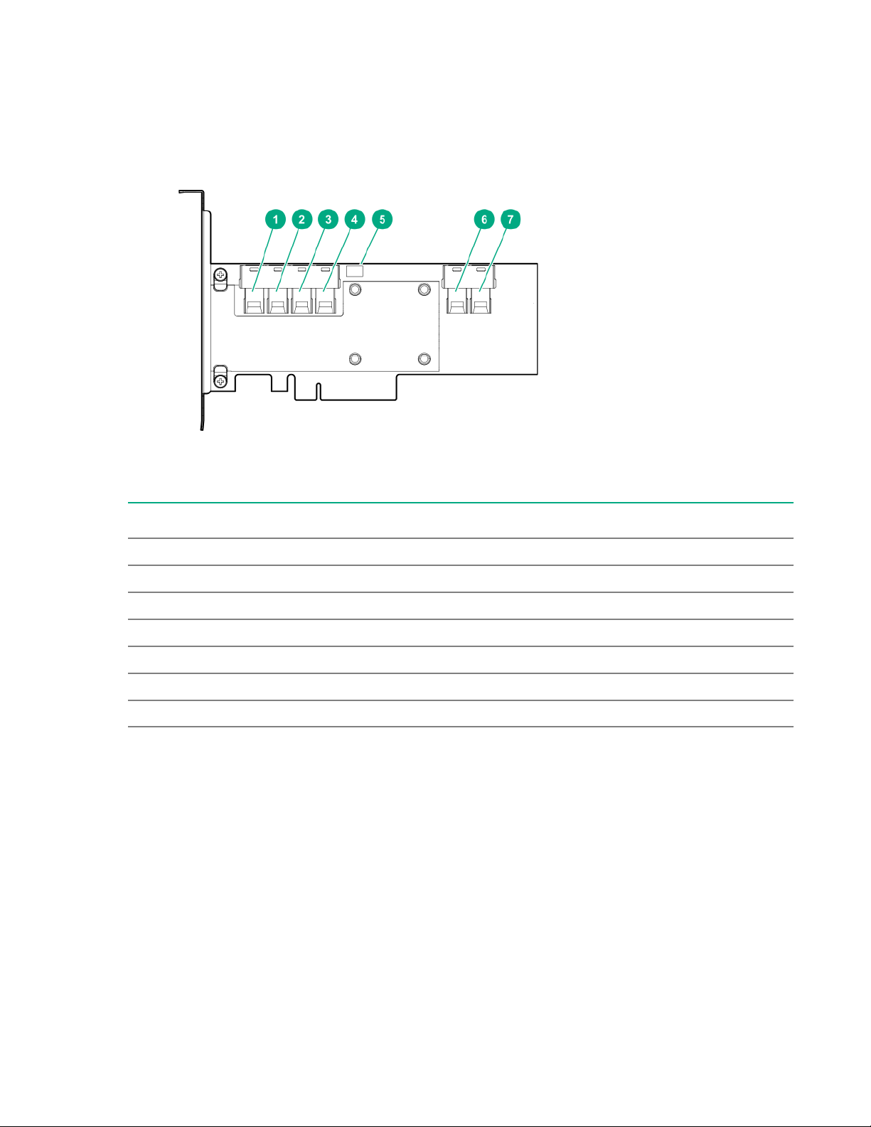
Models
HPE Smart Array P824i-p MR Gen10 Controller
Components
Item Description
1 Internal SAS port 1i
2 Internal SAS port 2i
3 Internal SAS port 3i
4 Internal SAS port 4i
5 Controller backup power cable connector
6 Internal SAS port 5i
7 Internal SAS port 6i
Models 59
Page 60
Energy pack options
Hewlett Packard Enterprise offers two centralized backup power source options to back up write cache
content on P-class Smart Array controllers in case of an unplanned server power outage.
•
HPE Smart Storage Battery
• HPE Smart Storage Hybrid Capacitor
IMPORTANT: The HPE Smart Storage Hybrid Capacitor is only supported on Gen10 and later
servers that support the 96W HPE Smart Storage Battery.
One energy pack option can support multiple devices. An energy pack option is required for P-class
Smart Array controllers. Once installed, the status of the energy pack displays in HPE iLO. For more
information, see the HPE iLO user guide on the Hewlett Packard Enterprise website (http://
www.hpe.com/support/ilo-docs).
HPE Smart Storage Battery
The HPE Smart Storage Battery supports the following devices:
• HPE Smart Storage SR controllers
• HPE Smart Storage MR controllers
A single 96W battery can support up to 24 devices.
After the battery is installed, it might take up to two hours to charge. Controller features requiring backup
power are not re-enabled until the battery is capable of supporting the backup power.
HPE Smart Storage Hybrid Capacitor
The HPE Smart Storage Hybrid Capacitor supports the following devices:
• HPE Smart Storage SR controllers
• HPE Smart Storage MR controllers
The capacitor pack can support up to three devices or 600 joules.
Before installing the HPE Smart Storage Hybrid Capacitor, verify that the system BIOS meets the
minimum firmware requirements to support the capacitor pack.
IMPORTANT: If the system BIOS or controller firmware is older than the minimum recommended
firmware versions, the capacitor pack will only support one device.
The capacitor pack is fully charged after the system boots.
60 Energy pack options
Page 61

Energy pack specifications
Table 1: HPE Smart Storage Battery (96W)
Feature Description
Time required to recharge Smart Storage Battery 96 W: 2 hours (For maximum load of 24 devices)
Duration of Smart Storage Battery backup
For more information, see the QuickSpecs document for the Smart Storage Battery.
150 seconds (maximum support)
The Smart Storage Battery provides a sufficient
duration to transfer the cached data from DDR
memory to flash memory, where the data remains
indefinitely or until a controller retrieves the data.
Table 2: HPE Smart Storage Battery (12W)
Feature Description
Time required to recharge Smart Storage Battery 12 W: 1 hour (For maximum load of 3 devices)
Duration of Smart Storage Battery backup
For more information, see the QuickSpecs document for the Smart Storage Battery.
150 seconds (maximum support)
The Smart Storage Battery provides a sufficient
duration to transfer the cached data from DDR
memory to flash memory, where the data remains
indefinitely or until a controller retrieves the data.
Table 3: HPE Smart Storage Hybrid Capacitor
Feature Description
Time required to recharge capacitor pack Not applicable; charge is immediate
Duration of capacitor pack backup
The capacitor pack can be used in place of the 96 W Smart Storage Battery, but it is not supported on the
Apollo servers.
For more information, see the QuickSpecs document for the capacitor pack.
60 seconds
The capacitor pack provides a sufficient duration to
transfer the cached data from DDR memory to
flash memory, where the data remains indefinitely
or until a controller retrieves the data.
Energy pack options 61
Page 62

Specifications
Memory and storage capacity conventions
Memory capacities are specified using binary prefixes:
• KiB = 210 bytes
• MiB = 220 bytes
• GiB = 230 bytes
• TiB = 240 bytes
Storage capacities are specified using SI prefixes:
• KB = 103 bytes
• MB = 106 bytes
• GB = 109 bytes
• TB = 1012 bytes
Older, and other, documentation may use SI prefixes for binary values.
Actual available memory capacity and actual formatted storage capacity for devices are less than
specified values.
RAID conventions
Hewlett Packard Enterprise uses the following naming convention for RAID levels:
• RAID 0
• RAID 1
• RAID 10
• RAID 5
• RAID 50
• RAID 6
• RAID 60
RAID 50 and RAID 60 are also known in the industry as RAID 5+0 and RAID 6+0, respectively.
Controller specifications
For more information about the specifications for the controller, see the quick specs document.
62 Specifications
Page 63

Support and other resources
Accessing Hewlett Packard Enterprise Support
• For live assistance, go to the Contact Hewlett Packard Enterprise Worldwide website:
http://www.hpe.com/info/assistance
• To access documentation and support services, go to the Hewlett Packard Enterprise Support Center
website:
http://www.hpe.com/support/hpesc
Information to collect
• Technical support registration number (if applicable)
• Product name, model or version, and serial number
• Operating system name and version
• Firmware version
• Error messages
• Product-specific reports and logs
• Add-on products or components
• Third-party products or components
Accessing updates
• Some software products provide a mechanism for accessing software updates through the product
interface. Review your product documentation to identify the recommended software update method.
• To download product updates:
Hewlett Packard Enterprise Support Center
www.hpe.com/support/hpesc
Hewlett Packard Enterprise Support Center: Software downloads
www.hpe.com/support/downloads
Software Depot
www.hpe.com/support/softwaredepot
• To subscribe to eNewsletters and alerts:
www.hpe.com/support/e-updates
• To view and update your entitlements, and to link your contracts and warranties with your profile, go to
the Hewlett Packard Enterprise Support Center More Information on Access to Support Materials
page:
www.hpe.com/support/AccessToSupportMaterials
Support and other resources 63
Page 64

IMPORTANT: Access to some updates might require product entitlement when accessed through
the Hewlett Packard Enterprise Support Center. You must have an HPE Passport set up with
relevant entitlements.
Customer self repair
Hewlett Packard Enterprise customer self repair (CSR) programs allow you to repair your product. If a
CSR part needs to be replaced, it will be shipped directly to you so that you can install it at your
convenience. Some parts do not qualify for CSR. Your Hewlett Packard Enterprise authorized service
provider will determine whether a repair can be accomplished by CSR.
For more information about CSR, contact your local service provider or go to the CSR website:
http://www.hpe.com/support/selfrepair
Remote support
Remote support is available with supported devices as part of your warranty or contractual support
agreement. It provides intelligent event diagnosis, and automatic, secure submission of hardware event
notifications to Hewlett Packard Enterprise, which will initiate a fast and accurate resolution based on your
product's service level. Hewlett Packard Enterprise strongly recommends that you register your device for
remote support.
If your product includes additional remote support details, use search to locate that information.
Remote support and Proactive Care information
HPE Get Connected
www.hpe.com/services/getconnected
HPE Proactive Care services
www.hpe.com/services/proactivecare
HPE Proactive Care service: Supported products list
www.hpe.com/services/proactivecaresupportedproducts
HPE Proactive Care advanced service: Supported products list
www.hpe.com/services/proactivecareadvancedsupportedproducts
Proactive Care customer information
Proactive Care central
www.hpe.com/services/proactivecarecentral
Proactive Care service activation
www.hpe.com/services/proactivecarecentralgetstarted
Warranty information
To view the warranty information for your product, see the links provided below:
HPE ProLiant and IA-32 Servers and Options
www.hpe.com/support/ProLiantServers-Warranties
HPE Enterprise and Cloudline Servers
www.hpe.com/support/EnterpriseServers-Warranties
HPE Storage Products
www.hpe.com/support/Storage-Warranties
HPE Networking Products
www.hpe.com/support/Networking-Warranties
64 Support and other resources
Page 65

Regulatory information
To view the regulatory information for your product, view the Safety and Compliance Information for
Server, Storage, Power, Networking, and Rack Products, available at the Hewlett Packard Enterprise
Support Center:
www.hpe.com/support/Safety-Compliance-EnterpriseProducts
Additional regulatory information
Hewlett Packard Enterprise is committed to providing our customers with information about the chemical
substances in our products as needed to comply with legal requirements such as REACH (Regulation EC
No 1907/2006 of the European Parliament and the Council). A chemical information report for this product
can be found at:
www.hpe.com/info/reach
For Hewlett Packard Enterprise product environmental and safety information and compliance data,
including RoHS and REACH, see:
www.hpe.com/info/ecodata
For Hewlett Packard Enterprise environmental information, including company programs, product
recycling, and energy efficiency, see:
www.hpe.com/info/environment
Documentation feedback
Hewlett Packard Enterprise is committed to providing documentation that meets your needs. To help us
improve the documentation, send any errors, suggestions, or comments to Documentation Feedback
([email protected]). When submitting your feedback, include the document title, part number,
edition, and publication date located on the front cover of the document. For online help content, include
the product name, product version, help edition, and publication date located on the legal notices page.
Support and other resources 65
Page 66

Websites
General websites
Hewlett Packard Enterprise Information Library
www.hpe.com/info/EIL
Subscription Service/Support Alerts
www.hpe.com/support/e-updates
Insight Remote Support
www.hpe.com/info/insightremotesupport/docs
For additional general support websites, see Support and other resources.
Product websites
HPE Smart Array
http://www.hpe.com/info/P824i-pdocs
HPE Integrated Lights-Out
www.hpe.com/info/ilo
66 Websites
 Loading...