

Page 1

HP ProLiant Essentials Rapid Deployment Pack
User Guide
Part number 315378-402
Eleventh edition August 2007
Product version: 3.70
Page 2

Legal notices
© Copyright 2001, 2007 Hewlett-Packard Development Company, L.P.
Confidential computer software. Valid license from HP required for possession, use or copying. Consistent with FAR 12.211
and 12.212, Commercial Computer Software, Computer Software Documentation, and Technical Data for Commercial
Items are licensed to the U.S. Government under vendor's standard commercial license.
The information contained herein is subject to change without notice. The only warranties for HP products and services are
set forth in the express warranty statements accompanying such products and services. Nothing herein should be construed
as constituting an additional warranty. HP shall not be liable for technical or editorial errors or omissions contained herein.
Microsoft and Windows are U.S. registered trademarks of Microsoft Corporation.
Product version: 3.70
Page 3

Contents 3
Contents
1 Configuring the Rapid Deployment Pack.......................................................................................... 5
Configuring BladeSystem enclosures........................................................................................................... 5
Configuring image installs......................................................................................................................... 6
Configuring imaging jobs .................................................................................................................... 6
Configuring Windows Sysprep jobs ...................................................................................................... 6
Configuring scripted installs ...................................................................................................................... 7
Configuring scripted install jobs ............................................................................................................ 7
Configuring SAN-attached scripted install jobs........................................................................................ 7
Configuring Boot from SAN scripted install jobs...................................................................................... 8
2 Using the Rapid Deployment Pack ..................................................................................................9
Connecting server blades.......................................................................................................................... 9
Creating a reference server and image..................................................................................................... 12
Deploying a captured image to other similar servers................................................................................... 14
Reconfiguring the new servers ................................................................................................................. 15
Maintaining server blades with rip-and-replace.......................................................................................... 17
Performing a Boot from SAN installation ................................................................................................... 18
3 Understanding the Deployment Server........................................................................................... 20
Jobs ..................................................................................................................................................... 20
Job default settings................................................................................................................................. 21
Hardware configuration settings.......................................................................................................... 21
Operating system scripted install settings.............................................................................................. 21
How a job is run on a target ................................................................................................................... 24
Deployment Server directory structure ....................................................................................................... 28
4 Customizing the ProLiant and Integrity Integration Modules..............................................................29
Getting started....................................................................................................................................... 29
Customizing jobs .............................................................................................................................. 29
Customizing files............................................................................................................................... 30
Reasons to customize the Integration Modules............................................................................................ 30
All operating systems......................................................................................................................... 30
Windows unattend text files................................................................................................................ 30
VMware ESX Server kickstart files........................................................................................................ 31
Virtual Machine jobs ......................................................................................................................... 31
Red Hat Linux kickstart files ................................................................................................................ 31
SUSE Linux control files...................................................................................................................... 31
Customization examples ......................................................................................................................... 31
Example 1—Using a specific ProLiant Support Pack version.................................................................... 31
Example 2—Modifying the Windows unattend text files......................................................................... 32
Example 3—Modifying the Red Hat Linux kickstart files.......................................................................... 32
Example 4—Modifying the Altiris Deployment Agent for Linux ................................................................32
Example 5—Modifying a Create Virtual Machine job for custom virtual values ......................................... 32
5 HP support and contact information ..............................................................................................33
Related documents ................................................................................................................................. 33
Online resources.................................................................................................................................... 33
HP contact information ........................................................................................................................... 33
HP Software Technical Support and Update Service ................................................................................... 34
Page 4

Contents 4
Index ..................................................................................................................................................35
Page 5

Configuring the Rapid Deployment Pack 5
1 Configuring the Rapid Deployment Pack
The following sections detail the configuration steps necessary to deploy an operating system to a
server.
Configuring BladeSystem enclosures
The Physical Devices view in the Deployment Server Console displays the physical relationship
between the racks, enclosures, and server blades using the rack name and enclosure name for each
HP BladeSystem server. The display name for a new server blade is a combination of the rack name,
enclosure name, and bay number. Before you connect the first server in an enclosure to the
Deployment Server, assign the rack and enclosure with unique names to prevent conflicting database
entries.
If the BladeSystem servers are powered up before the rack name and enclosure name have been
changed, the names are recorded in the Deployment Server database and appear in the Deployment
Server Console. If the names are changed after being recorded in the Deployment Server database,
then the servers must be rebooted for the new rack name and enclosure name to be discovered. In
addition, the original default rack names and the default enclosure names must be manually deleted
from the console.
To change the rack name and enclosure name, follow the procedure specific to each server type:
• ProLiant BL p-Class servers—Place at least one server blade in each enclosure, and before
powering up the server blade, change the rack and enclosure information using the Integrated
Lights-Out (iLO) interface. For details about accessing iLO to change the rack name and
enclosure name, see the documentation shipped with your server blade.
• HP BladeSystem c-Class servers—To access the Onboard Administrator and change the rack
name and the enclosure name, see the server documentation.
Page 6

Configuring the Rapid Deployment Pack 6
Configuring image installs
IMPORTANT: By default, the Create Disk Image and Distribute Disk Image tasks operate on the
“first” disk. The disks are enumerated using a proprietary algorithm. The “first” disk might not be the
system boot disk. The Altiris showdisk utility can be used to generate human-readable disk
enumeration output. This utility is called in the provided Read Hardware Configuration job. For more
information on reading the showdisk output, see the Rapid Deployment Pack Knowledge Base at
http://www.hp.com/servers/rdp/kb
.
Configuring imaging jobs
When capturing or deploying an image to a server with multiple disks, either DAS or SAN, you might
have to specify the system boot disk in the job.
To specify a particular disk:
1. In the Deployment Server Console, copy, rename, and edit the job.
2. Modify the Create Disk Image or Distribute Disk Image task.
3. In the Additional Parameteres box, add the -dx switch, where x is an integer that represents the
appropriate disk number.
When deploying Red Hat Enterprise Linux with LVM, x must be a comma-separated list of
integers representing all of the disk numbers that the LVM volume will span. For example, to
deploy an LVM image that spans the first three disks, use -d1, 2, 3.
Configuring Windows Sysprep jobs
In addition to the steps in the “Configuring imaging jobs” section, the Windows® Sysprep jobs
require a product key and cannot use the product keys entered during the Integration Module
installation.
For each Capture Windows Sysprep Image job:
1. Select the Create Disk Image task.
2. Click Modify.
3. In the Sysprep settings box, select Add new from the Operating System list.
4. On the OS Product Key screen, select the appropriate operating system.
5. Click Add to enter a new product key.
6. Enter the product key in the Product Key box, and click OK>Finish.
For each Deploy Windows Sysprep Image job:
1. Select the Distribute Disk Image task.
2. Click Modify.
3. In the Sysprep settings box, select the appropriate operating system from the Operating System
list.
4. Select the appropriate product key from the Product key list, and click Finish.
Page 7

Configuring the Rapid Deployment Pack 7
Configuring scripted installs
Configuring scripted install jobs
The scripted install jobs use a small image to partition and format the disk. When deploying to a
server with multiple disks, either DAS or SAN, you might have to specify the system boot disk in the
job for the NTFS.img or GRUB.img images. For more information, see the “Configuring image
installs” section.
To specify a particular disk:
1. In the Deployment Server Console, copy, rename, and edit the job.
2. Modify the Distribute Disk Image task.
3. In the Additional Parameteres box, add the -dx switch, where x is an integer that represents the
appropriate disk number.
Additionally, for Red Hat Linux in a multiple disk scenario, the kickstart file must specify the system
boot disk.
1. On the Deployment Server, copy and rename the kickstart file.
2. Modify the new kickstart file by replacing the autopart command with separate part command
lines and adding the ---ondisk=XXX option to each where XXX is the device label.
Example for non-LVM:
part /boot --size 75 --ondisk=cciss/c0d0
part swap –size=1000 --ondisk=cciss/c0d0
part / --size 5120 -–grow --ondisk=cciss/c0d0
Example for LVM:
part /boot --size 100 --fstype=ext3 --ondisk=cciss/c0d0
part pv.01 --size=100 --grow --ondisk=cciss/c0d0
volgroup VolGroup00 -–pesize=32768 pv.01
3. In the Deployment Server Console, copy, rename, and edit the job.
4. Edit the Run Script – Create Boot Environment task in the new job to use the new kickstart file
created in step 2.
Configuring SAN-attached scripted install jobs
In addition to the steps in the “Configuring scripted install jobs” section, some further steps might be
necessary.
For VMware ESX Server 3.0.x:
Disconnect the SAN. After the operating system install is complete, reconnect the SAN and create a
VMFS datastore on it.
Page 8

Configuring the Rapid Deployment Pack 8
For VMware ESX 2.5.3:
1. On the Deployment Server, copy, rename, and edit the job.
2. Modify the Run Script – Create Boot Environment task in the new job by changing the
default.cfg file reference in the # replacetokens statement to sanattach.cfg.
3. Execute the new job.
After the operating system installation is complete, using the MUI:
4. Create the core dump partition.
a. Click Reconfigure when the following warning message appears:
No core dump partition is configured or none is accessible
b. Select the LUN on which to place the core dump partition. The core dump partition cannot be
created on the local ATA drive.
c. Set the size of the core dump partition. VMware recommends 100 MB for each VMware ESX
Server. The partition size defaults to all remaining available LUN space.
5. Create the Virtual Machine File System (VMFS).
a. Select Storage Management. Available storage volumes and available space are displayed.
The VMFS cannot be created on a local ATA drive.
b. Select Create Volume/Name.
c. Select Typical or Custom. A typical volume allocates all remaining space to the VMFS.
Configuring Boot from SAN scripted install jobs
In addition to the steps in the “Configuring scripted install jobs” section, some further steps may be
necessary.
For VMware ESX Server 2.5.3:
1. On the Deployment Server, copy, rename, and edit the job.
2. Modify the Run Script – Create Boot Environment task in the new job by uncommetting the
export bootfromsan=yes line.
Page 9

Using the Rapid Deployment Pack 9
2 Using the Rapid Deployment Pack
This section provides information about the following topics:
• Connecting server blades
• Creating a reference server and image
• Deploying a captured image to other similar servers
• Reconfiguring the new servers
• Maintaining server blades with rip-and-replace
• Performing a Boot from SAN installation
Connecting server blades
1. Connect the enclosure to the network that contains your Deployment Server, and power up the
enclosure.
2. Insert the server blades into the enclosure, but do not power on the server blades.
3. Change the default rack and enclosure names.
4. Power up the server blades.
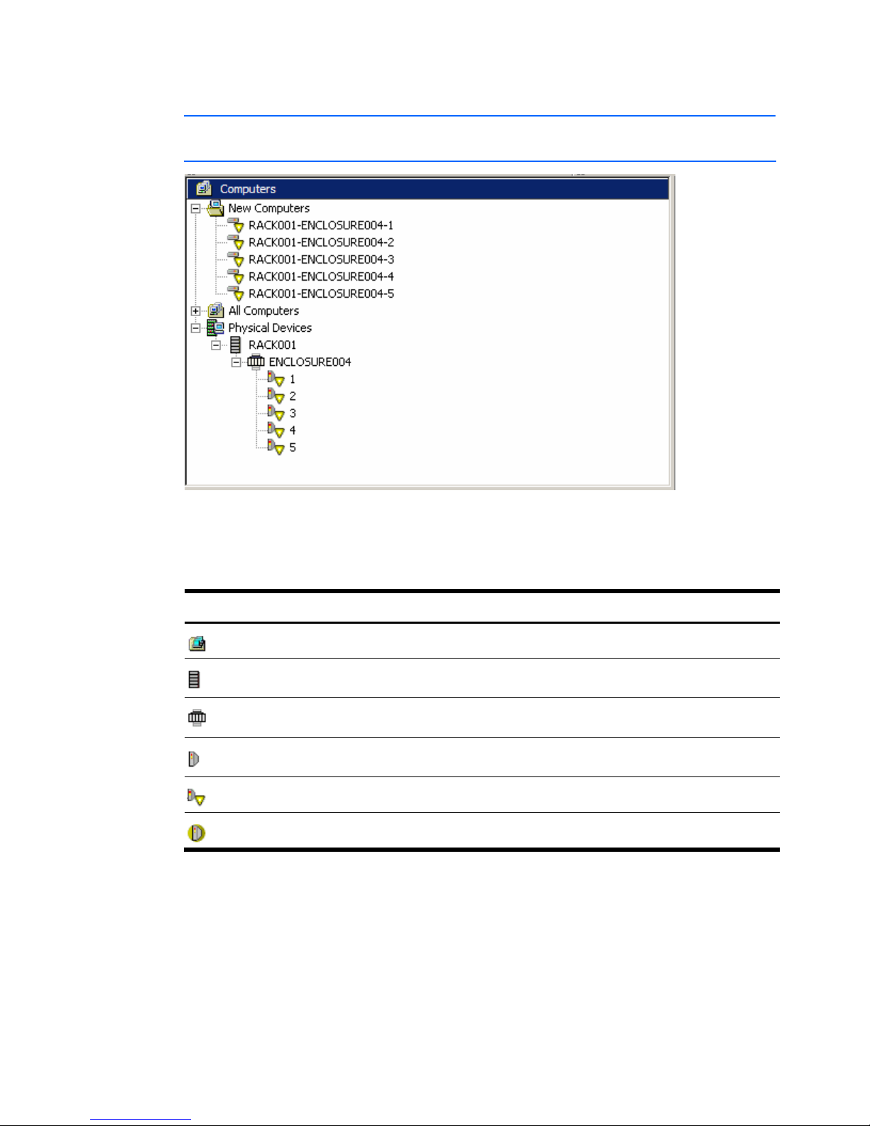
5. Open the Deployment Server Console to view target servers available for deployment and
management. The following panes appear in the console:
• Computers—This pane is located on the upper-left side of the console and displays, by
default, New Computers and All Computers. Virtual Machines and Physical Devices are also
displayed (if enabled).
• Jobs—This pane is located on the lower-left side of the console and lists the jobs provided
with the Rapid Deployment Pack.
• Details—This pane is located on the right side of the console and displays details for the
selections highlighted within the Computers pane or the Jobs pane.
Page 10
Using the Rapid Deployment Pack 10
6.
Select View>Show Physical Devices.
NOTE: The Physical Devices view is an additional view available only for BladeSystem servers
in the Computers pane. A job can be executed on a server listed in this view.
Table 1 lists the server icons displayed in the Physical Devices view of the Deployment Server
Console.
Table 1 Server icons
Icon Description
Indicates a grouping of physical devices
Indicates a rack
Indicates an enclosure
Indicates a single server blade in a bay
Indicates an unconfigured server blade in a waiting state designated by the user
Indicates a virtual bay
Page 11
Using the Rapid Deployment Pack 11
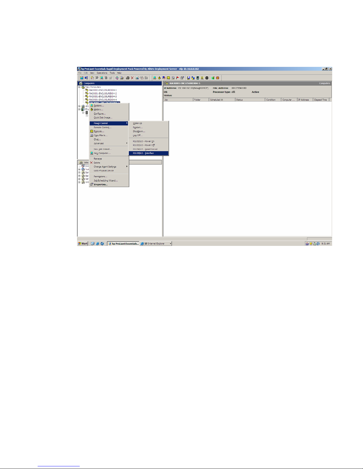
7.
From the Computers pane, right-click on a server blade.
8. Select Power Control>RILOE/iLO – Interface. This action accesses the iLO, iLO 2, or RILOE
interface to enable remote viewing of the deployment.
Page 12
Using the Rapid Deployment Pack 12
Creating a reference server and image
The initial server blade must be deployed using a scripted installation job. Subsequent server blades
can be deployed by capturing and deploying the image of the initial server blade.
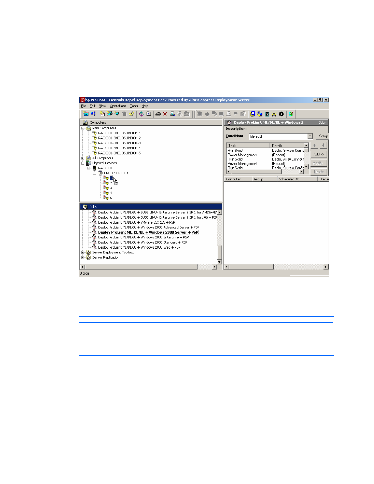
1. In the Jobs pane, select a Windows-scripted installation job in the Server Deployment folder.
Drag the job onto the initial server blade in the Computers pane.
2. Select Run this job immediately, and click OK.
NOTE: The Details pane displays the job currently running. Double-clicking the job in the
Details pane shows the tasks and status.
NOTE: The Windows-scripted installations perform a token-replace of the computer name from
the Deployment Server Console name. This computer name is truncated to the right-most 15
characters to comply with the NETBIOS limitation. The Linux- and VMware-scripted installs use
the Deployment Server Console display name as the server host name.
Page 13

Using the Rapid Deployment Pack 13
3.
In the Jobs pane, find the Read ProLiant ML/DL/BL System and Array Configuration and
Windows Image {WinPE} job in the Server Replication folder. Drag the job onto the initial server
blade in the Computers pane.
NOTE: The Server Replication jobs provided with the Rapid Deployment Pack create and
deploy images using an image name based on the computer model names. If you use the
provided jobs without modification, each time you capture a new image on the same computer
model, the previous image is overwritten.
4. Select Run this job immediately, and click OK.
5. If the scripted installation job is still running on the server, click OK when the warning message
appears.
Page 14

Using the Rapid Deployment Pack 14
Deploying a captured image to other similar
servers
1. In the Computers pane, select the rest of the server blades. Drag them onto the Write ProLiant
ML/DL/BL System and Array Configuration and Windows Image {WinPE} job in the Server
Replication folder in the Jobs pane.
If you are deploying the image to all server blades in an enclosure, you can select the enclosure
from the Physical Devices view.
2. Select Run this job immediately, and click OK.
Page 15

Using the Rapid Deployment Pack 15
Reconfiguring the new servers
1. In the Computers pane, select all the server blades, and then right-click the selection, and select
Configure.
2. Click Microsoft Networking, and then enter a new workgroup or domain name (if applicable),
and click Define Range.
3. Enter the fixed portion of the new server names, and click OK.
Page 16

Using the Rapid Deployment Pack 16
4.
Click TCP/IP, enter the IP information for the first server blade, and click OK. Subsequent server
blades are assigned the same information, except that the IP address increases incrementally for
each server blade.
5. Select Run this job immediately, and click OK.
Page 17

Using the Rapid Deployment Pack 17
Maintaining server blades with rip-and-replace
When a failed server blade is replaced, the Deployment Server can automatically replay the job
history of the failed server blade on the new server blade. This feature is available only for
BladeSystem servers.
NOTE: The new server blade requires a new license. The existing license cannot be transferred to
the new server blade.
To enable rip-and-replace, perform the following steps for each server blade:
1. In the Computers pane, right-click a single server, and select Properties.
2. Scroll down, and click Bay.
3. Select Re-Deploy Computer from the Server change rule list, and click OK.
The following server change rule options are available:
• Re-Deploy Computer—Takes the job history of the previous server blade and replays it on the
new server blade. The replay starts from the last deployment type job. This option is available
only after the server blade is deployed or a virtual bay has been created.
• Run Predefined Job—Processes any job specified by the user, including the Initial Deployment
job.
• Wait for User Interaction—Performs no job. The Deployment Agent on the server blade is
instructed to wait and the icon in the console is changed to reflect a waiting server.
• Ignore the Change—Ignores the new server blade, meaning that no jobs are initiated. If the new
server blade existed in a previous bay, the history and parameters for the server are moved or
associated with the new bay. If the server blade is not listed in the database, its properties are
associated with the bay, and the normal process defined for new servers (if any) is followed.
Page 18

Using the Rapid Deployment Pack 18
Performing a Boot from SAN installation
A Boot from SAN (BFS) installation requires several manual steps before starting the operation system
installation.
Be sure the following prerequisites are met:
• The target server is cabled in a single-path configuration (with only one channel active). You
can cable both paths after the operating system installed and the multipathing software is
installed.
• Only one LUN is presented to the target server.
• Review HP StorageWorks Booting Windows Systems from a Storage Area Network
Application Notes and HP StorageWorks Booting Linux Systems from a Storage Area
Network Application Notes for details about SAN configuration and minimum firmware
requirements.
1. Configure the SAN storage for the target server.
a. Run the appropriate platform Read HBA Configuration job from the Server Deployment
Toolbox\1—Hardware Configuration\HBA job folder on the target server. This job creates
the .\lib\hwconfig\hba\ID.ini file, where ID is the target server computer ID. The
following is an example of a generated file:
[HBA0]
WWID=500508b200713e72
HostAdapterBiosEnable=1
SelectBootEnable=1
BootDeviceWWID=
BootDeviceLUN=
[HBA1]
WWID=500508b200713e73
HostAdapterBiosEnable=0
SelectBootEnable=0
BootDeviceWWID=
BootDeviceLUN=
NOTE: To determine the target server computer ID, in the Computers pane, double-click on
the target server and read the ID field.
b. Create a LUN for the boot volume of the target server. Record the created LUN and the
World Wide Identification (WWID) of the boot controller.
c. Using the target server HBA WWID from the file created in step 1a, configure the SAN
switches for zoning or Selective Storage Presentation as needed in your environment.
2. Configure the target server HBA to boot from the configured SAN storage.
a. Edit the ID.ini file created in step 1a, adding the previously recorded boot controller WWID
and LUN. The boot volume must be set up as the first visible LUN. The following is an
example of an edited file:
[HBA0]
WWID=500508b200713e72
HostAdapterBiosEnable=1
SelectBootEnable=1
BootDeviceWWID=395442c135713a41
BootDeviceLUN=01
[HBA1]
WWID=500508b200713e73
HostAdapterBiosEnable=0
SelectBootEnable=0
Page 19

Using the Rapid Deployment Pack 19
BootDeviceWWID=395442c135713a42
BootDeviceLUN=01
b. Run the appropriate platform Write HBA Configuration job from the Server Deployment
Toolbox\1—Hardware Configuration\HBA job folder on the target server.
c. For ProLiant servers, run the Deploy ProLiant BL System Configuration (Boot From SAN)
{LinuxPE} or {WinPE} job from the Server Deployment Toolbox\1—Hardware
Configuration\System job folder on the target server. This job disables the embedded array
controller and places the HBA controller first in the boot order.
3. Execute the appropriate operating system installation job from the Server Deployment Toolbox.
Page 20

Understanding the Deployment Server 20
3 Understanding the Deployment Server
The Rapid Deployment Pack populates the Deployment Server Console with jobs and the Deployment
Server directory with tools, scripts, configuration files, software drivers, and documentation files. This
section explains these provided jobs and files, and the directory structure.
Jobs
The Rapid Deployment Pack adds four root folders into the Jobs pane.
Table 2
Job folders
Folder Description
Server Deployment The jobs in this folder perform a complete server deployment. They deploy a
default hardware configuration, execute a scripted operating system installation,
and install the appropriate ProLiant or Integrity Support Pack.
Server Deployment Toolbox The jobs in this folder provide more granular control over the server deployment
process. By providing jobs that perform only hardware configuration, operating
system installation, and value-add software installation, you can easily combine
various jobs together to suit your needs.
Server Replication The jobs in this folder perform replication from a reference server to a target
server that is of the same server model with the same hardware configuration.
Virtual Machine Deployment
Toolbox
The jobs in this folder provide the ability to create a VMware ESX virtual machine
and to deploy an operating system to a virtual machine.
Page 21

Understanding the Deployment Server 21
Job default settings
Unless otherwise indicated in the job name, the job uses the following default settings. For details
about how to customize these default settings, see the “Customizing the ProLiant and Integrity
Integration Modules” section in this guide.
Hardware configuration settings
Table 3 Hardware default settings
Component Default setting
System ROM Factory defaults
Smart Array Based on the number of attached drives
iLO Not configured in the standard jobs
SAN HBA Not configured in the standard jobs
Operating system scripted install settings
The provided Windows scripted install jobs use the default configuration parameters listed in Table 4
Windows default settings.
Table 4
Windows default settings
Component Default setting
Windows administrator
password
The administrator password is password. This password is stored as clear text in
the unattend answer file. HP recommends changing the default administrator
password within the unattend answer file located in the .\lib\osconfig\yyyy
directory on the Deployment Server, where yyyy is the operating system shortcut
name.
Drive configuration A single partition is created automatically that expands to the full drive size.
Computer name The Windows computer name uses the 15 right-most characters of the display
name shown in the Deployment Server Console.
Page 22

Understanding the Deployment Server 22
The provided VMware scripted install jobs use the default configuration parameters listed in Table 5
VMware default settings.
Table 5
VMware default settings
Component Default setting
VMware root password The root password is password. This password is stored as clear text in the
kickstart file. HP recommends that you change the root password to your own
password and in encrypted form within the kickstart file located in the
.\lib\osconfig\yyyy directory on the Deployment Server where yyyy is the
operating system shortcut name.
Drive configuration When configuring the disk partition for a scripted operating system installation,
various VMware ESX Server specific partitions are created. These are the
default settings and must not be changed.
Host name The VMware ESX Server host name uses the display name that appears in the
Deployment Server Console.
Packages VMware ESX Server specific packages are installed. Do not change this setting.
Firewall Firewall settings are disabled.
The provided Red Hat Linux and SUSE Linux scripted install jobs use the default configuration
parameters listed in Table 6
Linux default settings.
Table 6
Linux default settings
Component Default setting
Linux root password The root password is password. This password is stored as clear text in the
kickstart/control file. HP recommends that you change the root password to your own
password and in encrypted form within the kickstart/control file located in the
.\lib\osconfig\yyyy directory on the Deployment Server where yyyy is the operating
system shortcut name.
Drive configuration The disk space is partitioned according to Red Hat or SUSE Linux default
specifications. Red Hat Enterprise Linux installs Logical Volume Manager (LVM) by
default.
Host name The Linux host name uses the display name that appears in the Deployment Server
Console.
Packages Basic Linux server packages are installed.
Firewall Firewall settings are disabled.
Page 23

Understanding the Deployment Server 23
Read/Write job filenames
The provided Read (Capture)/Write jobs use the default input/output filenames listed in Table 7
Default Read (Capture)/Write jobs.
Table 7
Default Read (Capture)/Write jobs
Read(Capture)/Write Job Pair Filename
Server Deployment Toolbox > 1 – Hardware Configuration
ProLiant ML/DL/BL System Configuration .\lib\hwconfig\system\pl-capture.xml
ProLiant ML/DL/BL Array Configuration .\lib\hwconfig\array\pl-capture.ini
ProLiant ML/DL/BL HBA Configuration [server specific] .\lib\hwconfig\hba\ID.ini where ID is the server ID
number as given by Deployment Server
Integrity RX/BL System Configuration .\lib\hwconfig\system\i-capture.xml
Integrity RX/BL Array Configuration .\lib\hwconfig\array\i-capture.ini
Server Deployment Toolbox > 2A – OS Installation (Imaged)
Windows Image .\lib\images\capture-windows.img
Linux Image .\lib\images\capture-linux.img
Server Deployment Toolbox > 2C – OS Installation (SysPrep)
Windows xxxx Sysprep Image .\lib\images\xxxx-sysprep.img where xxxx is the
operating system name and shortcut name
Server Replication
ProLiant ML/DL/BL System and Array Configuration and
Windows Image
.\lib\hwconfig\system\yyyy-windows.xml
.\lib\hwconfig\array\yyyy-windows.ini
.\lib\images\yyyy-windows.img
Where yyyy is the computer model name, for
example ProLiant DL360 G4.
ProLiant ML/DL/BL System and Array Configuration and
Linux Image
.\lib\hwconfig\system\yyyy-linux.xml
.\lib\hwconfig\array\yyyy-linux.ini
.\lib\images\yyyy-linux.img
Where yyyy is the computer model name, for
example ProLiant DL360 G4.
Integrity RX/BL System and Array Configuration and
Linux Image
.\lib\hwconfig\system\yyyy-linux.xml
.\lib\hwconfig\array\yyyy-linux.ini
.\lib\images\yyyy-linux.img
Where yyyy is the computer model name, for
example ProLiant DL360 G4.
Page 24

Understanding the Deployment Server 24
How a job is run on a target
This section provides a walkthrough of how a job is executed on a target server. The table within
each step lists the state of the target server and the job action during that execution step.
The term “automation environment” is used throughout this section. It is an operating system in which
scripts can be run on the target independent of the target’s production operating system or the
Deployment Server operating system. The target can boot the automation environment either from a
CD-ROM, USB key, or through PXE. The Rapid Deployment Pack supports the following automation
environments: Linux x86 and ia64 (hereafter LinuxPE) and WinPE 1.6 x86 and x64. Each automation
environment consists of the necessary base files, additional HP drivers, and the appropriate Altiris
Deployment Agent.
NOTE: A CD-ROM or USB key can only hold one automation environment. Many of the jobs use
multiple automation environments. This means that as the job progresses, the boot media must be
swapped accordingly.
The Run Script, Create Disk Image, and Distribute Disk Image tasks enable the user to specify which
automation environment to run in. The Rapid Deployment Pack jobs specify a specific automation
environment to avoid ambiguity and to ensure that the utilities run in the correct and tested
environment.
1. Power up the bare-metal target server. Since the target does not have a bootable hard drive, the
boot order attempts a PXE boot. The PXE Server sends it the Initial Deploy boot option image. By
default, this is Linux Managed (auto-select). The Deployment Agent connects to the Deployment
Server. Since this is the initial connection and no pending job exists, the Deployment Server
directs the Deployment Agent to wait.
Table 8
Step 1
Target Server LinuxPE, waiting
2. Schedule the "Deploy ProLiant ML/DL/BL + Windows 2003 x64 Enterprise + PSP" job on the
target.
Table 9
Step 2
Target Server LinuxPE, waiting
Job Task 1—Deploy System Configuration {WinPE 32-bit}, pending
3. The Deployment Server determines that the target is in the incorrect automation environment. It
directs the Deployment Agent to set the one-time boot EV to PXE and then reboot. When the
target reboots to PXE, the PXE Server sends it the WinPE 32-bit image.
Table 10
Step 3
Target Server Rebooting to WinPE Managed 32-bit
Job Task 1— Deploy System Configuration {WinPE 32-bit}, pending
Page 25

Understanding the Deployment Server 25
4.
When the Deployment Agent connects to the Deployment Server, task 1of the job begins to
execute.
Table 11
Step 4
Target Server WinPE Managed 32-bit, executing task
Job Task 1—Deploy System Configuration {WinPE 32-bit}
set inputfile=pl.xml
call %altiris_share%\lib\bin32\winpe\conrep.cmd –l %inputfile%
5. Task 2 in the job is a Reboot. By looking ahead at task 3, the Deployment Server directs the
Deployment Agent to set the One-Time Boot EV to PXE and then reboot. When the target reboots
to PXE, the PXE Server sends it the WinPE Managed 32-bit image.
This reboot is necessary in case any Smart Array controllers are disabled in the conrep file.
Table 12
Step 5
Target Server Rebooting to WinPE 32-bit
Job Task 2—Reboot
6. When the Deployment Agent connects to the Deployment Server, the task 3 of the job begins to
execute.
Table 13
Step 6
Target Server WinPE 32-bit, executing task
Job Task 3—Deploy Array Configuration {WinPE 32-bit}
set inputfile=pl-acu--d.ini
call %altiris_share%\lib\bin32\winpe\acu.cmd –I %inputfile%
7. Task 4 in the job is a Reboot. By looking ahead at task 5, the Deployment Server directs the
Deployment Agent to set the One-Time Boot EV to PXE and then reboot. When the target reboots
to PXE, the PXE Server sends it the WinPE Managed 32-bit image.
This reboot is mandatory so that the subsequent imaging task is able to see the new hard drive.
Table 14
Step 7
Target Server Rebooting to WinPE 32-bit
Job Task 4—Reboot
8. When the Deployment Agent connects to the Deployment Server, task 5 of the job begins to
execute.
Table 15
Step 8
Target Server WinPE 32-bit, executing task
Job Task 5—Deploy System Configuration {WinPE 32-bit}
set inputfile=pl-win.xml
call %altiris_share%\lib\bin32\winpe\conrep.cmd –l %inputfile%
Page 26

Understanding the Deployment Server 26
9.
The Deployment Agent begins executing task 6 of the job.
Table 16
Step 9
Target Server WinPE 32-bit, executing task
Job Task 6—Distribute Disk Image {WinPE 32-bit}
.\lib\images\NTFS.IMG
10. Task 7 in the job is a Reboot. By looking ahead at task 8, the Deployment Server directs the
Deployment Agent to set the one-time boot EV to PXE and then reboot. When the targets reboot
to PXE, the PXE Server sends it the WinPE 64-bit image.
This reboot is mandatory so that the subsequent file copy tasks are able to use the new hard
drive.
Table 17
Step 10
Target Server Rebooting to WinPE 64-bit
Job Task 7—Reboot
11. When the Deployment Agent connects to the Deployment Server, task 8 of the job begins to
execute. Since tasks 8 through 12 all run in WinPE 64-bit without a Reboot task, they execute
sequentially while in WinPE 64-bit.
Table 18
Step 11
Target Server
WinPE 64-bit, executing tasks
Task 8—Copy ProLiant Files {WinPE 64-bit}
set oem=proliant.zzz\w52.64
call %altiris_share%\lib\bin64\winpe\osoem1.cmd
Task 9—Copy Altiris Files {WinPE 64-bit}
rem replacetokens .\lib\osoem\altiris\aclient.txt .\lib\osoem\altiris\%ID%.inp
set configfile=%ID%.inp
call %altiris_share%\lib\bin64\winpe\osoem2.cmd
Task 10—Copy Unattend.txt {WinPE 64-bit}
rem replacetokens .\lib\osconfig\w52e.64\default.txt .\lib\osconfig\w52e.64\%ID%.txt
set unattendfile=w52e.64\%ID%.txt
call %ALTIRIS_SHARE%\lib\bin64\winpe\osconfig1.cmd
Task 11—Copy Distribution Files {WinPE 64-bit}
set dist=w52e.64
call %altiris_share%\lib\bin64\winpe\osdist1.cmd
Job
Task 12—Start Install {WinPE 64-bit}
set HD=c
for %%i in (c d e f g h i j k l m) do if exist %%i:\rdpimage set HD=%%i
%HD%:\amd64\winnt32.exe /s:%HD%:\amd64 /unattend:%HD%:\unattend.txt
/syspart:%HD%: /tempdrive:%HD%:
Page 27

Understanding the Deployment Server 27
12.
After completing task 12, the Deployment Server looks ahead at task 13. Task 13 runs in
Windows production. Therefore, the Deployment Server directs the Deployment Agent to reboot.
When the target reboots, it boots to the hard drive because it is before PXE in the default boot
order.
Table 19
Step 12
Target Server
Executing Windows-scripted install
Job
Task 13—Install Package {Windows}, pending
13. The Deployment Agent for Windows is installed as part of the Windows-scripted install. The
Deployment Agent loads upon the first real Windows production boot. When it connects to the
Deployment Server, task 13 of the job begins to execute.
Table 20
Step 13
Target Server
Windows, executing task
Job Task 13—Install Package {Windows}
.\lib\software\ProLiant Support Pack Z.ZZ for Windows 2003
x64\setupex.exe
14. The last task in the job is a Reboot. The Deployment Server tells the Deployment Agent to reboot.
This reboot is mandatory so that the new and updated drivers installed by the ProLiant Support
Pack get loaded properly.
Table 21
Step 14
Target Server
Rebooting to Windows
Job Task 14—Reboot
Page 28

Understanding the Deployment Server 28
Deployment Server directory structure
The following table provides an overview of the Deployment Server directory as populated by the
Rapid Deployment Pack.
Table 22
Deployment Server directory structure
Directory Description
.\docs
• Rapid Deployment Pack and SmartStart Scripting Toolkit documentation in Portable
Document Format (.pdf)
.\jobs
• The .bin files for the provided jobs
.\lib\bin32
• Various Windows x86 and Linux x86 tools and scripts
• Windows SmartStart Scripting Toolkit
• Linux SmartStart Scripting Toolkit
.\lib\bin64
• Various Windows x64 tools and scripts
.\lib\binia64
• Various Windows ia64 and Linux ia64 tools and scripts
• Smart Setup Scripting Toolkit for Integrity
.\lib\hwconfig
• Presupplied and captured hardware configuration files.
.\lib\images
• Presupplied and captured image files.
.\lib\osconfig
• Operating system scripted install answer files separated into subdirectories per OS.
.\lib\osdist
• Operating system distribution files separated into subdirectories per OS. Each
subdirectory contains the entire contents of the source DVD or CD-ROM(s).
.\lib\osoem
• ProLiant Drivers for Windows Scripted Installs
• Integrity Drivers for Windows Scripted Installs
• Altiris Deployment Agents
• Integrity Support Packs
• The proliant.xxx or integrity.xxx subdirectories are either a specific version number, such
as 7.70 or Z.ZZ which is a copy of the latest version subfolder. The Z.ZZ subfolder is
used by the provided scripted install jobs.
.\lib\ossysprep
• Operating system sysprep imaging answer files.
.\lib\software
• ProLiant Support Packs
• ProLiant Firmware Updates
• Integrity Support Packs
• The Support Pack x.xx subdirectories are either a specific version number such as 7.70 or
Z.ZZ which is a copy of the latest version subfolder. The Z.ZZ subfolder is used by the
provided scripted install jobs.
Page 29

Customizing the ProLiant and Integrity Integration Modules 29
4 Customizing the ProLiant and Integrity
Integration Modules
Getting started
Before modifying the provided jobs, folders, and files, make a copy of the job, files, or both and use
this copy for your custom work. Keeping the original job and files ensures that a working version
exists. If you encounter a problem or if you select to overwrite the jobs or files during an upgrade or
reinstallation of the Rapid Deployment Pack, your customized job or file is not overwritten.
Customizing jobs
This section explains how to copy, paste, rename, and edit a job in the Deployment Server Console
Jobs pane. For more information about the customization features of the Deployment Server Console,
see the Altiris Deployment Solution 6.8 Deployment and Migration Guide at
http://www.hp.com/servers/rdp
.
NOTE: The jobs in the Rapid Deployment Pack use long names to be descriptive. When attempting
to copy these jobs to the same directory as the original job, the name might be truncated by Altiris
because it places “Copy of” in front of the job causing it to exceed the 128-character limit of the
Deployment Server Console.
To copy, paste, rename, and edit a job:
1. Right-click the job, and select Copy.
2. Right-click another location in the Jobs pane, and select Paste.
3. Right-click the new job, select Rename, or select the new job and press F2.
4. Enter a descriptive name for the job, and press Enter.
5. Select the new job.
6. In the Details pane, double-click a task to edit its contents.
Export or import a job from a file as a method of backing up a job or a job folder. Job files are
usually denoted with the .bin extension.
Page 30

Customizing the ProLiant and Integrity Integration Modules 30
To export a job or folder:
1. Right-click the job or folder.
2. Select Export.
3. On the Export Selected Job(s)/Folder(s) screen, click Browse to designate a directory and job
file, or enter the path and file name in the Export to File Name field. If you want to export the
subfolders of a folder, select Export subfolders.
4. Click OK.
To import a job or folder:
1. Right-click within the Jobs pane.
2. Select Import.
3. On the Import Job screen, click Browse to locate the directory and job file, or enter the path and
file name in the Job file to import field.
4. Select the appropriate checkboxes, and then click OK.
Customizing files
On the Deployment Server, copy, paste, rename, and edit the file using the appropriate operating
system commands. After the new file is created, modify the job as described in the previous section to
use the new file name.
NOTE: If editing VMware ESX or Linux files on the Deployment Server, use a text editor that saves
the file in Linux compatible format without adding extra characters.
Reasons to customize the Integration Modules
The following sections provide information about why you might want to customize the ProLiant
Integration Module or Integrity Integration Module. For more information about customizing your
installations, see the Rapid Deployment Pack Knowledge Base at
http://www.hp.com/servers/rdp/kb
.
All operating systems
• Change the array configuration
• Use a specific version of ProLiant Support Pack or Integrity Support Pack
• Modify the Altiris Deployment Agent settings (aclient or adlagent)
Windows unattend text files
• Specify the SNMP community string and trap destinations
• Change the administrator password
• Specify a domain
Page 31

Customizing the ProLiant and Integrity Integration Modules 31
VMware ESX Server kickstart files
• Change the default root password
HP recommends that you do not modify the VMware ESX Server kickstart file with other modifications.
For supported VMware kickstart options, see http://www.vmware.com
.
Virtual Machine jobs
• Change the virtual disk size
• Change the virtual memory size
For more information, see the VMware Virtual Infrastructure SDK Reference Guide at
https://www.vmware.com/pdf/SDKReferenceGuide.pdf
.
Red Hat Linux kickstart files
• Change the default root password
• Add a grub bootloader password
• Change the partitions, types, and sizes
• Change the Linux packages that are installed
• Change the firewall settings
• Add additional post installation commands
For information about editing the kickstart files, see the Red Hat Linux Customization Guide located at
http://www.redhat.com
.
SUSE Linux control files
• Change the default root password
• Add a grub bootloader password
• Change the partitions, types, and sizes
• Change the Linux packages that are installed
• Change the firewall settings
• Add additional post installation commands
For more information about editing the control files, see the AutoYast2 documentation at
http://www.suse.com/~ug/autoyast_doc/index.html
.
Customization examples
This section provides specific examples of customizing a few of the ProLiant Integration Module
components.
Example 1—Using a specific ProLiant Support Pack version
To use a specific ProLiant Support Pack:
1. If the intended ProLiant Support Pack is newer than what exists on the Deployment Server:
a. Create the appropriate .\lib\software\ProLiant Support Pack yyyy directory, where yyyy is
the operating system name and support pack version.
Page 32

Customizing the ProLiant and Integrity Integration Modules 32
b.
Download and extract the support pack to the new directory.
c. For VMware and Linux, copy rdpinstall.sh and rdpinstall.dat from a similar support pack to
the new directory.
2. In the Deployment Server Console, copy, rename, and edit the job.
a. For Windows, modify the Install Package task to reference the chosen directory.
b. For VMware or Linux, modify the Copy File to task to reference the chosen directory.
Example 2—Modifying the Windows unattend text files
To use a custom Windows unattend text file:
1. On the Deployment Server, copy, rename, and modify the unattend text file.
2. In the Deployment Server Console, copy, rename, and edit the job.
3. Modify the Run Script – Copy Unattend.txt task in this job by changing the rem replacetokens
line to reference the new unattend text file.
Example 3—Modifying the Red Hat Linux kickstart files
To use a custom Red Hat Linux kickstart file:
1. On the Deployment Server, copy, rename, and modify the kickstart file.
2. In the Deployment Server Console, copy, rename, and edit the job.
3. Modify the Run Script - Create Boot Environment task in this job by changing the #replacetokens
line to reference the new kickstart file.
Example 4—Modifying the Altiris Deployment Agent for Linux
The Altiris Deployment Agent for Linux, adlagent, uses an adlagent configuration file adlagent.conf, to
read its settings. This file can be modified and then deployed during the Linux installation for adlagent
to read at startup. All Linux deployments use this custom adlagent configuration file. To change the
adlagent settings:
1. Copy the adlagent.conf file from a working target server to the Deployment Server in the
.\lib\osoem\altiris directory.
2. Rename the file to adlagent.conf.custom.
3. Modify the file for your specific settings.
Example 5—Modifying a Create Virtual Machine job for
custom virtual values
To change the Create Virtual Machine job to use different virtual-disk-size or virtual-memory-size
values:
1. In the Deployment Server Console, copy, rename, and edit a Create Virtual Machine job.
2. Modify the Run Script – Create and power on Virtual Machine task, remove the comment and
change the VMDISKSIZE= or VMMEMSIZE= values to new values. Some possible values are
listed in the comments of this task. For more information, see the VMware Virtual Infrastructure
SDK Reference Guide at https://www.vmware.com/pdf/SDKReferenceGuide.pdf
.
Page 33

HP support and contact information 33
5 HP support and contact information
Related documents
HP recommends reviewing the following documentation before reading this guide:
• HP ProLiant Essentials Rapid Deployment Pack Planning Guide
• HP ProLiant Essentials Rapid Deployment Pack Installation Guide
• HP ProLiant Essentials Rapid Deployment Pack Knowledge Base at
http://www.hp.com/servers/rdp/kb
which includes the latest Deployment Support article.
All PDF documents can be found at http://www.hp.com/servers/rdp
and at \docs on the product
DVD.
Online resources
• Information about the Rapid Deployment Pack and the latest updates are available from the
HP ProLiant Essentials Rapid Deployment Pack website at http://www.hp.com/servers/rdp
.
• Problem-solving information and ideas from other IT professionals are available in the IT
Resource Center (ITRC) User Forum “ProLiant Deployment & Provisioning.” You can access this
forum from the Management Software and System Tools link at http://forums.itrc.hp.com
.
• Information and resources about the Altiris Deployment Solution are available from the Altiris
website at http://www.altiris.com
.
HP contact information
For the name of the nearest HP authorized reseller:
• In the United States, see the HP U.S. service locator webpage at
http://www.hp.com/service_locator
.
• In other locations, see the Contact HP worldwide webpage at
http://welcome.hp.com/country/us/en/wwcontact.html
.
For HP technical support:
• In the United States, for contact options see the Contact HP United States webpage at
http://welcome.hp.com/country/us/en/contact_us.html
. To contact HP by phone:
• Call 1-800-HP-INVENT (1-800-474-6836). This service is available 24 hours a day, 7 days a
week. For continuous quality improvement, calls may be recorded or monitored.
• In other locations, see the Contact HP worldwide webpage at
http://welcome.hp.com/country/us/en/wwcontact.html
.
Page 34

HP support and contact information 34
HP Software Technical Support and Update Service
HP ProLiant Essentials Rapid Deployment Pack now includes one year of 24 x 7 HP Software
Technical Support and Update Service. This service provides access to HP technical resources to help
you resolve software implementation or operations problems. The service also provides access to
software updates and reference manuals either in electronic format or on physical media, as they are
made available from HP.
With this service, HP ProLiant Essentials Rapid Deployment Pack customers benefit from expedited
problem resolution and proactive notification and delivery of HP ProLiant Essentials Rapid Deployment
Pack software updates.
To activate your HP Software Technical Support and Update Service for HP ProLiant Essentials Rapid
Deployment Pack, you must register your software purchase through the HP website at
http://www.hp.com/go/insightcontrolregistration
.
Failure to register your service will jeopardize service fulfillment.
Your Service Agreement Identifier (SAID) will be delivered to you after registration. After you have
received your SAID, you can go to the software update manager (SUM) web page to view your
contract and elect electronic delivery (in addition to standard media-based updates). For more
information about this service, see
http://www.hp.com/services/insight.
In addition to the new Software Technical Support and Update Service, HP also offers a number of
additional software support services, many of which are provided to our customers at no additional
charge.
• Warranty—HP will replace defective delivery media for a period of 90 days from the date of
purchase. This warranty applies to all Insight Control Management, HP Systems Insight
Manager, and ProLiant Essentials products.
• Startup technical software support—Phone support is available to help you with basic installation
and setup and usage questions. This support is provided by the knowledgeable HP Insight
Control Management and Systems Insight Manager specialists’ team and is available for no
additional charge up to 90 days from the date of purchase of your server. For support in the
U.S., call 1-800-HP-INVENT (1-800-474-6836). (When prompted, say "Insight Manager, P2P,
and SMP.") HP Worldwide support numbers for HP SIM, P2P, and SMP are available at
http://www.hp.com/country/us/en/wwcontact.html
• Join the discussion (http://forums.itrc.hp.com)—The HP Support Forum is a community-based,
user-supported tool for HP customers to participate in discussions amongst the customer
community about HP products. For discussions related to Insight Control and ProLiant Essentials
software, click Management software and system tools.
• Software and Drivers download pages (http://www.hp.com/support)—These pages provide
latest software and drivers for your ProLiant products.
• Management Security (http://www.hp.com/servers/manage/security)—HP is proactive in its
approach to the quality and security of all its management software. Be sure to check this
website often for the latest downloadable security updates.
• Obtain the latest SmartStart (http://www.hp.com/servers/smartstart)—The SmartStart,
Management, and Firmware CDs are now available for free download by following a simple
registration from the SmartStart website. To receive physical kits with each release, order single
release kits from the SmartStart website. To receive proactive notification when SmartStart
releases are available, subscribe to Subscriber's Choice at
http://www.hp.com/go/subscriberschoice
.
Page 35

Index 35
Index
A
Altiris Deployment Agent for Linux
modifying, 32
B
bay properties rule configuration, 17
BIOS settings, 21
Boot from SAN installation, 18
Boot from SAN scripted install jobs, 8
C
change rule setting, 17
changing enclosure names, 5
configuring
HP BladeSystem servers, 5, 9
image installs, 6
rip-and-replace, 17
scripted installs, 7
contact information, 33
control files
customizing, 31
copying
files, 30
jobs, 29
creating
image, 12
reference server, 12
customize text files, 30
customizing
control files, 31
examples, 31
kickstart files, 31
ProLiant Integration Module, 29
reasons, 30
scripted install, 20
unattend text files, 30
virtual machine jobs, 31
customizing files, 30
Customizing the ProLiant and Integrity Integration
Modules, 29
D
deploying
imaging, 14, 15
setting change rule, 17
Deployment Server
directory structure, 20
Deployment Server directory structure, 28
disk partition, configuration, 21
E
editing
files, 30
enabling rip-and-replace, 17
enclosure
changing names, 5
F
files
customizing, 30
H
hardware configuration
default settings, 21
deploying, 14, 15
How a job is run on a target
automation environment, 24
HP authorized reseller, 33
HP BladeSystem servers
configuring, 5, 9
deploying, 14, 15
enabling rip-and-replace, 17
Physical Devices view, 5
HP Getting started, 29
HP Hardware configuration settings, 21
HP ProLiant Support Pack, using a specific version, 31
HP Software Technical Support and Update Service, 34
HP Support and Contact information, 33
I
ignore change option, 17
iLO. See Integrated Lights-Out
imaging
creating, 12
deploying, 14, 15
imaging jobs, 6
Page 36

Index 36
initial deployment job, 17
installation settings
Red Hat Linux, 23
Windows, 21
Integrated Administrator, 5
Integrated Lights-Out, 5
J
Job default settings, 21
jobs
customizing, 29
server deployment, 20
server deployment toolbox, 20
server replication, 20
virtual machine, 31
virtual machine deployment toolbox, 20
K
kickstart files
customizing, 31
L
Linux
customizing kickstart files, 31
scripted install, 20
Linux kickstart files, 32
Linux Kickstart files
modifying, 32
M
Modifying a Create Virtual Machine job, 32
Modifying the Windows unattend text file, 32
N
NIC, Integrated Administrator, 5
O
online resources, 33
operating system
deploying, 14, 15
operating systems, 30
P
pasting
files, 30
jobs, 29
Physical Devices view
configuring, 5
Preboot eXecution Environment
booting, 9
ProLiant Integration Module, customizing, 29
R
rack name, 5
RAID settings, 21
Red Hat Linux
customizing kickstart files, 31
installation settings, 23
scripted install, 20
redeployment option, 17
reference server, creating, 12
Related documents, 33
remote management, 5
renaming
files, 30
jobs, 29
rip-and-replace, 17
run job option, 17
S
SAN-attached scripted install jobs, 7
scripted install
customizing, 20
scripted install, 7
scripted installs, 7
SmartStart Scripting Toolkit, configuring hardware, 21
Software
support, 34
SUSE Linux
customizing control files, 31
scripted install, 20
U
unattend text file
modifying, 32
unattend text files
customizing, 30
Understanding the Deployment Server, 20
usage scenario, 9
Using a specific ProLiant Support Pack version, 31
V
virtual machines
customizing jobs, 31
VMware
customizing kickstart files, 31
scripted install, 20
Page 37

Index 37
W
wait option, 17
Windows
customizing unattend text files, 30
installation settings, 21
Windows Sysprep images, 6
Windows Sysprep jobs, 6
 Loading...