

Page 1

User Guide
HP USB Barcode Scanner
for Point of Sale System
Document Part Number:419218-002
August 2006
Print this document before setting up the HP USB Barcode
Scanner. The document provides the programming bar codes
necessary for selecting features for the scanner.
Page 2

© Copyright 2006 Hewlett-Packard Development Company, L.P.
The information contained herein is subject to change without notice.
The only warranties for HP products and services are set forth in the
express warranty statements accompanying such products and services.
Nothing herein should be construed as constituting an additional warranty.
HP shall not be liable for technical or editorial errors or omissions
contained herein.
This document contains proprietary information that is protected by
copyright. No part of this document may be photocopied, reproduced, or
translated to another language without the prior written consent of
Hewlett-Packard Company.
WARNING: Text set off in this manner indicates that failure to
Å
follow directions could result in bodily harm or loss of life.
CAUTION: Text set off in this manner indicates that failure to follow
Ä
directions could result in damage to equipment or loss of information.
User Guide
HP USB Barcode Scanner
First Edition (August 2006)
Document Part Number: 419218-002
Page 3

Contents
1Product Features
Identifying Barcode Scanner Components. . . . . . . . . . . . 1–2
2 Safety and Maintenance Guidelines
Important Safety Information. . . . . . . . . . . . . . . . . . . . . . 2–1
Maintenance Guidelines. . . . . . . . . . . . . . . . . . . . . . . . . . 2–3
3 Setting Up the Scanner
Connecting the USB Interface Cable . . . . . . . . . . . . . . . . 3–1
Removing the USB Interface Cable . . . . . . . . . . . . . 3–2
Assembling the Stand. . . . . . . . . . . . . . . . . . . . . . . . . . . . 3–2
Mounting the Stand . . . . . . . . . . . . . . . . . . . . . . . . . . . . . 3–3
Screw Mount . . . . . . . . . . . . . . . . . . . . . . . . . . . . . . . 3–3
Tape Mount . . . . . . . . . . . . . . . . . . . . . . . . . . . . . . . . 3–4
Setting Up the USB Interface. . . . . . . . . . . . . . . . . . . . . . 3–4
USB Default Parameters . . . . . . . . . . . . . . . . . . . . . . . . . 3–5
Parameters Descriptions. . . . . . . . . . . . . . . . . . . . . . . . . . 3–6
USB Country Keyboard Types (Country Codes) . . . 3–6
USB Caps Lock Override . . . . . . . . . . . . . . . . . . . . 3–11
USB Ignore Unknown Characters . . . . . . . . . . . . . . 3–12
Emulate Keypad . . . . . . . . . . . . . . . . . . . . . . . . . . . 3–13
USB Keyboard FN 1 Substitution . . . . . . . . . . . . . . 3–13
Function Key Mapping . . . . . . . . . . . . . . . . . . . . . . 3–14
Simulated Caps Lock. . . . . . . . . . . . . . . . . . . . . . . . 3–14
Convert Case . . . . . . . . . . . . . . . . . . . . . . . . . . . . . . 3–15
USB ASCII Character Set . . . . . . . . . . . . . . . . . . . . 3–16
User Guide www.hp.com iii
Page 4

Contents
4 Operating the Scanner
Defining Beeper Sequences . . . . . . . . . . . . . . . . . . . . . . . 4–1
Defining LED Indicators . . . . . . . . . . . . . . . . . . . . . . . . . 4–3
Scanning in Hand-Held Mode . . . . . . . . . . . . . . . . . . . . . 4–4
Aiming the Scanner . . . . . . . . . . . . . . . . . . . . . . . . . . . . . 4–5
Scanning in Hands-Free Mode. . . . . . . . . . . . . . . . . . . . . 4–6
5 Programming User Preferences
Scanning Sequence Examples . . . . . . . . . . . . . . . . . . . . . 5–1
Errors While Scanning . . . . . . . . . . . . . . . . . . . . . . . . . . . 5–2
User Preferences Default Parameters. . . . . . . . . . . . . . . . 5–2
User Preferences. . . . . . . . . . . . . . . . . . . . . . . . . . . . . . . . 5–3
Set Default Parameter . . . . . . . . . . . . . . . . . . . . . . . . 5–3
Beeper Tone. . . . . . . . . . . . . . . . . . . . . . . . . . . . . . . . 5–4
Beeper Volume . . . . . . . . . . . . . . . . . . . . . . . . . . . . . 5–5
Power Mode. . . . . . . . . . . . . . . . . . . . . . . . . . . . . . . . 5–6
Laser On Time. . . . . . . . . . . . . . . . . . . . . . . . . . . . . . 5–7
Beep After Good Decode . . . . . . . . . . . . . . . . . . . . . 5–8
ATroubleshooting
Solving Common Problems . . . . . . . . . . . . . . . . . . . . . . . A–1
Using the Worldwide Web. . . . . . . . . . . . . . . . . . . . . . . . A–2
Preparing to Call Technical Support . . . . . . . . . . . . . . . . A–2
B Technical Specifications
Decode Zone . . . . . . . . . . . . . . . . . . . . . . . . . . . . . . . . . . B–3
Disposal of Waste Equipment by Users in Private Household
in the European Union . . . . . . . . . . . . . . . . . . . . . . . . . . . B–4
iv www.hp.com User Guide
Page 5

1
Product Features
The HP USB Barcode Scanner is designed to work with point of
sale system hardware and program applications. The barcode
scanner features:
■ Hand-held or hands-free scanning operation.
■ Stand assembly kit for hands free operation.
■ USB connection that autodetects a USB host and defaults to
the HID keyboard interface type.
■ USB cable assembly provided.
■ Supports international keyboards for Microsoft Windows
environment: North America, German, French, Spanish,
Italian, Swedish, Brazilian Portuguese and Japanese.
User Guide www.hp.com 1–1
Page 6
Product Features
■ Software and regulatory notices for this product are available
on the Point of Sale System Software and Documentation CD.
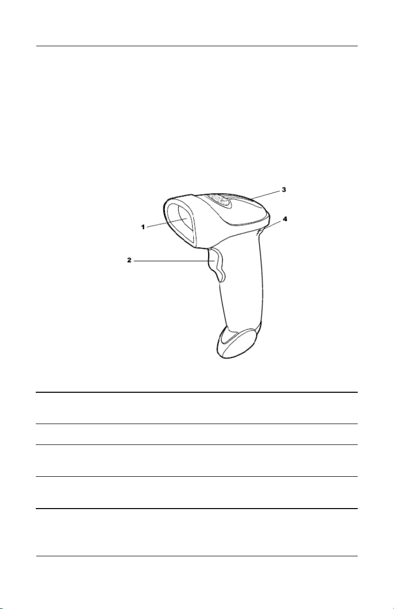
Identifying Barcode Scanner Components
1 Scan Window - scans bar code symbols with laser light and produces a
digitized pattern that corresponds to the bars and spaces of the symbols.
2 Scan Trigger - press to scan bar codes.
3 LED - light indicator that communicates successful decoding, data
transmission error or malfunction.
4 Beeper - emits different beeper sequences and patterns that are defined by
you while programming the scanner and during normal scanning.
1–2 www.hp.com User Guide
Page 7

Safety and Maintenance
Guidelines
Important Safety Information
Follow the recommendations below to avoid potential risk of
ergonomic injury when using the HP USB Barcode Scanner.
WARNING: To reduce the risk of serious injury, read the Safety and
Å
Comfort Guide. It describes proper workstation, setup, posture, and
health habits for users, and provides important electrical and
mechanical safety information. This guide is located on the Web at
http://www.hp.com/ergo and/or on the documentation CD if one is
included with the product.
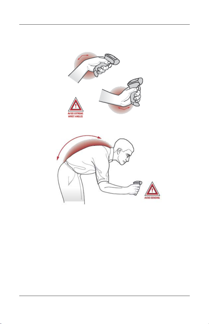
1. Use the optimum arm position.
2
User Guide www.hp.com 2–1
Page 8
Safety and Maintenance Guidelines
2. Avoid extreme wrist angles.
3. Avoid Bending.
2–2 www.hp.com User Guide
Page 9
Safety and Maintenance Guidelines
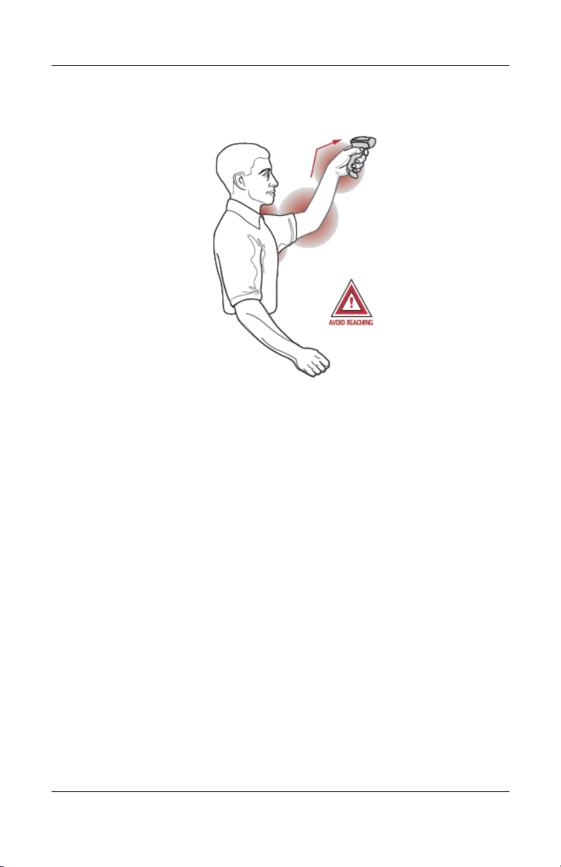
4. Avoid reaching.
Maintenance Guidelines
Cleaning the scan window is the only maintenance required. A
dirty window may affect scanning accuracy.
■ Do not allow any abrasive material to touch the window.
■ Remove any dirt particles with a damp cloth.
■ Wipe the window using a tissue moistened with mild
detergent and water.
■ Do not spray water or other cleaning liquids directly into the
window.
User Guide www.hp.com 2–3
Page 10

Safety and Maintenance Guidelines
2–4 www.hp.com User Guide
Page 11
Setting Up the Scanner
The scanner attaches directly to a USB port on the POS computer
and is powered by the computer. No additional power supply is
required.
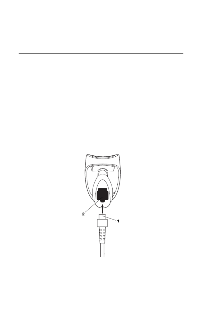
Connecting the USB Interface Cable
1. Plug the USB interface cable 1 into the cable interface port
2 on the bottom of the scanner.
3
User Guide www.hp.com 3–1
Page 12

Setting Up the Scanner
2. Gently tug the cable to ensure the connector is properly
secured.
3. Connect the other end of the interface cable into a USB port
on the POS computer.
Removing the USB Interface Cable
1. Unplug the installed cable’s modular connector by depressing
the connector clip with the tip of a screwdriver.
2. Carefully slide out the cable.
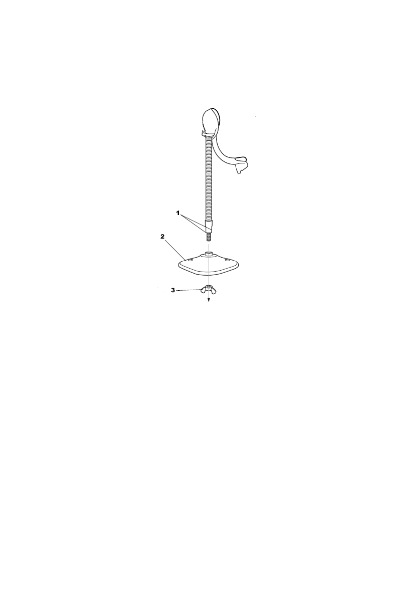
Assembling the Stand
The stand allows hands-free scanning when attached to the
scanner.
1. Unscrew the wingnut from the bottom of the neckpiece
scanner cup.
2. Fit the bottom of the neck piece 1 into the opening on the top
of the stand base 2.
3. Tighten the wingnut 3 underneath the base to secure the cup
and neck piece to the base.
Before tightening the wingnut under the base, ensure that the flat
✎
areas on the flexible neck fit securely in the grooves in the base.
3–2 www.hp.com User Guide
Page 13
Setting Up the Scanner
4. Bend the neck to the desired position for scanning.
Mounting the Stand
You can attach the base of the scanner’s stand to a flat surface
using two screws or double-side tape (not provided).
Screw Mount
1. Position the assembled base on a flat surface.
2. Screw one #10 wood screw (not provided) into each
screw-mount hole 1 until the base of the stand is secure.
User Guide www.hp.com 3–3
Page 14

Setting Up the Scanner
Tape Mount
1. Peel the paper liner off one side of each piece of tape (not
provided) 2 and place the sticky surface over each of the
three rectangular tape holders.
2. Peel the paper liner off the exposed sides of each piece of
tape and press the stand on a flat surface until it is secure.
Setting Up the USB Interface
To set up the scanner for USB:
1. Turn on the POS computer.
2. Using the barcode scanner, scan the HID Keyboard
Emulation barcode below.
*HID Keyboard Emulation
3. On first installation when using Windows, the software
prompts you to select or install the “Human Interface Device”
driver. To install the “Human Interface Device” driver
3–4 www.hp.com User Guide
Page 15

provided by Windows, click “Next” through all the choices
and click “Finished” on the last choice. The scanner powers
up during this installation.
4. If you are not using a North American keyboard, scan the
appropriate country bar code in USB Country Keyboard
Types (Country Codes) in this chapter.
USB Default Parameters
The following table lists the defaults for USB host parameters. If
you want to change any option, scan the appropriate bar codes
provided in the “Parameters Descriptions” section of this chapter.
Setting Up the Scanner
USB Host Default
Default
Parameters
USB Device Type HID Keyboard Emulation
USB Country Keyboard Types
(country codes)
USB Keystroke Delay No Delay
USB CAPS Lock Override Disable
USB Ignore Unknown Characters Enable
Emulate Keypad Disable
USB FN1 Substitution Disable
Function Key Mapping Disable
Simulated Caps Lock Disable
Convert Case None
North American
User Guide www.hp.com 3–5
Page 16

Setting Up the Scanner
Parameters Descriptions
USB Country Keyboard Types (Country Codes)
Scan the bar code corresponding to your country keyboard type.
This setting applies only to the USB HID (Human Interface
Devices) Keyboard Emulation device.
When changing country selection, the scanner automatically
✎
restarts. The scanner issues the standard startup beep sequences.
Throughout the programming bar code menus, default values are
✎
indicated with an asterisks (*).
3–6 www.hp.com User Guide
Page 17

Setting Up the Scanner
*North American Standard USB Keyboard
German Windows
French Windows
User Guide www.hp.com 3–7
Page 18

Setting Up the Scanner
French Canadian Windows 95/98
French Canadian Windows 2000/XP
Spanish Windows
Italian Windows
3–8 www.hp.com User Guide
Page 19

Swedish Windows
UK English Windows
Setting Up the Scanner
Japanese Windows (ASCII)
Portuguese-Brazilian Windows
User Guide www.hp.com 3–9
Page 20

Setting Up the Scanner
USB Keystroke Delay
This parameter sets the delay, in milliseconds, between emulated
keystrokes. Scan a barcode below to increase the delay when
hosts require a slower transmission of data.
*No Delay
Medium Delay (20 msec)
Long Delay (40 msec)
3–10 www.hp.com User Guide
Page 21

USB Caps Lock Override
When enabled, the case of the data is preserved regardless of the
state of the Caps Lock key. This setting is always enabled for the
“Japanese, Windows (ASCII)” keyboard type and can not be
disabled.
Override Caps Lock Key
(Enable)
Setting Up the Scanner
*Do Not Override Cap s Lock Key
(Disable)
User Guide www.hp.com 3–11
Page 22

Setting Up the Scanner
USB Ignore Unknown Characters
Unknown characters are characters the host does not recognize.
When “Send Bar Codes With Unknown Characters” is selected,
all bar code data is sent except for unknown characters, and no
error beeps sound. When “Do Not Send Bar Codes With
Unknown Characters” is selected, bar codes containing at least
one unknown character are not sent to the host, and an error beep
sounds.
*Send Bar Codes with Unknown Characters
Do Not Send Bar Codes with Unknown Characters
(Transmit)
(Disable)
3–12 www.hp.com User Guide
Page 23

Emulate Keypad
When enabled, all characters are sent as ASCII sequences over
the numeric keypad. For example ASCII A would be sent as
“ALT make” 0 6 5 “ALT Break”.
*Disable Keypad Emulation
Enable Keypad Emulation
USB Keyboard FN 1 Substitution
When enabled, this allows replacement of any FN 1 characters in
an EAN 128 bar code with a Key Category and value chosen by
the user (see FN 1 Substitution Values in chapter 3 of the
Programming Reference Guide to set the Key Category and Key
Va l ue ) .
Setting Up the Scanner
Enable
*Disable
User Guide www.hp.com 3–13
Page 24

Setting Up the Scanner
Function Key Mapping
ASCII values under 32 are normally sent as a control-key
sequences (see the USB ASCII Character Set table in this
chapter). When this parameter is enabled, the keys in bold in the
USB ASCII Character Set table are sent in place of the standard
key mapping. Table entries that do not have a bold entry remain
the same whether or not this parameter is enabled.
*Disable Function Key Mapping
Enable Function Key Mapping
Simulated Caps Lock
When enabled, the scanner will invert upper and lower case
characters on the scanner barcode as if the Caps Lock state is
enabled on the keyboard. This inversion is done regardless of the
current state of the keyboard’s Caps Lock state.
Disable Simulated Caps Lock
3–14 www.hp.com User Guide
Page 25

Convert Case
When enabled, the scanner will convert all bar code data to the
selected case.
Setting Up the Scanner
Enable Simulated Caps Lock
*No Case Conversion
Convert All to Upper Case
Convert All to Lower Case
User Guide www.hp.com 3–15
Page 26

Setting Up the Scanner
USB ASCII Character Set
This table provides ASCII character conversions for standard data
transmission code.
Prefix/Suffix
Value
1000 %U CTRL 2
1001 $A CT R L A
1002 $B CT R L B
1003 $C CTR L C
1004 $D CT RL D
1005 $E C T RL E
1006 $F CTRL F
1007 $G CT R L G
1008 $H CT RL
1009 $I CT RL
1010 $J CT RL J
Full ASCII Code
39 Encode Char.
Keystroke
H/BACKSPACE
I/HORIZONTAL
1
TAB
1
1011$K CTRL K
1012 $L CT R L L
1013 $M CT RL M / ENTER
1014 $N CT RL N
1015 $O C TRL 0
3–16 www.hp.com User Guide
1
Page 27

Setting Up the Scanner
Prefix/Suffix
Value
1016 $P C T RL P
1017 $Q C TRL Q
1018 $R CT R L R
1019 $S CTR L S
102 0 $T C TRL T
1021 $U CTR L U
1022 $V CTRL V
1023 $W CT R L W
1024 $X CT R L X
1025 $Y CTRL Y
1026 $Z CTR L Z
1027 %A CTRL [/ESC
1028 %B CTRL \
Full ASCII Code
39 Encode Char.
Keystroke
1
1029 %C CTRL ]
1030 %D CTRL 6
1031 %E CTRL -
1032 Space Space
1033 /A !
1034 /B “
1035 /C #
User Guide www.hp.com 3–17
Page 28

Setting Up the Scanner
Prefix/Suffix
Value
1036 /D $
1036 /D $
1037 /E %
1038 /F &
1039 /G ‘
1040 /H (
1041 /I )
1042 /J *
1043 /K +
1044 /L ‘
1045 - -
1046 . .
1047 /O /
Full ASCII Code
39 Encode Char.
Keystroke
1048 0 0
1049 1 1
1050 2 2
1051 3 3
1052 4 4
1053 5 5
1054 6 6
3–18 www.hp.com User Guide
Page 29

Setting Up the Scanner
Prefix/Suffix
Value
1055 7 7
1058 /Z :
1059 %F ;
1060 %G <
1061 %H =
1062 %I >
1063 %J ?
106 4 % V @
1065 A A
1066 B B
1067 C C
1068 D D
1069 E E
Full ASCII Code
39 Encode Char.
Keystroke
1070 F F
1071 G G
1072 H H
1073 I I
1074 J J
1075 K K
1076 L L
User Guide www.hp.com 3–19
Page 30

Setting Up the Scanner
Prefix/Suffix
Value
107 7 M M
1078 N N
1079 O O
1080 P P
1081 Q Q
1082 R R
1083 S S
1084 T T
1085 U U
1086 V V
1087 W W
1088 X X
1089 Y Y
Full ASCII Code
39 Encode Char.
Keystroke
1090 Z Z
1091 %K [
1092 %L \
1093 %M ]
1094 %N ^
1095 %O _
1096 %W ‘
3–20 www.hp.com User Guide
Page 31

Setting Up the Scanner
Prefix/Suffix
Value
1097 +A a
1098 +B b
1099 +C c
110 0 + D d
1101 + E e
110 2 + F f
110 3 + G g
110 4 + H h
110 5 + I i
110 6 + J j
110 7 + K k
110 8 + l l
110 9 + M m
Full ASCII Code
39 Encode Char.
Keystroke
1110 +N n
1111 + O o
1112 + P p
1113 + Q q
1114 + R r
1115 + S s
1116 + Y t
User Guide www.hp.com 3–21
Page 32

Setting Up the Scanner
Prefix/Suffix
Value
1117 + U u
1118 + V v
1119 + W w
11 2 0 + X x
11 2 1 + Y y
11 2 2 + Z z
11 2 3 % P {
11 2 4 % Q |
11 2 5 % R }
11 2 6 % S ~
1
The keystroke in bold is sent only if the “Function Key Mapping” is
enabled. Otherwise, the unbolden keystroke is sent.
Full ASCII Code
39 Encode Char.
Keystroke
ALT Keys Keystroke
2064 ALT 2
2065 ALT A
2066 ALT B
2067 ALT C
2068 ALT D
2069 ALT E
2070 ALT F
3–22 www.hp.com User Guide
Page 33

2071 ALT G
2072 ALT H
2073 ALT I
2074 ALT J
2075 ALT K
2076 ALT L
2077 ALT M
2078 ALT N
2079 ALT O
2080 ALT P
2081 ALT Q
2082 ALT R
Setting Up the Scanner
2083 ALT S
2084 ALT T
2085 ALT U
2086 ALT V
2087 ALT W
2088 ALT X
2089 ALT Y
2090 ALT Z
User Guide www.hp.com 3–23
Page 34

Setting Up the Scanner
GUI Shift Keys
Windows-based systems have a GUI key to the
left of the left ALT key and to the right of the right
ALT key.
Other Value Keystroke
3000 Right Control Key
3048 GUI 0
3049 GUI 1
3050 GUI 2
3051 GUI 3
3052 GUI 4
3053 GUI 5
3054 GUI 6
3055 GUI 7
3056 GUI 8
3057 GUI 9
3065 GUI A
3066 GUI B
3067 GUI C
3068 GUI D
3069 GUI E
3070 GUI F
3071 GUI G
3–24 www.hp.com User Guide
Page 35

3072 GUI H
3073 GUI I
3074 GUI J
3075 GUI K
3076 GUI L
3077 GUI M
3078 GUI N
3079 GUI O
3080 GUI P
3081 GUI Q
3082 GUI R
3083 GUI S
Setting Up the Scanner
3084 GUI T
3085 GUI U
3086 GUI V
3087 GUI W
3088 GUI X
3089 GUI Y
3090 GUI Z
F1 Keys Keystroke
5001 F1
User Guide www.hp.com 3–25
Page 36

Setting Up the Scanner
5002 F2
5003 F3
5004 F4
5005 F5
5006 F6
5007 F7
5008 F8
5009 F9
5010 F10
5011 F11
5012 F12
5013 F13
5014 F14
5015 F15
5016 F16
5017 F17
5018 F18
5019 F19
5020 F20
5021 F21
5022 F22
3–26 www.hp.com User Guide
Page 37

5023 F23
5024 F24
Keypad Keystroke
6042 *
6043 +
6044 undefined
6045 -
6046 .
6047 /
6048 0
6049 1
6050 2
Setting Up the Scanner
6051 3
6052 4
6053 5
6054 6
6055 7
6056 8
6057 9
6058 Enter
6059 Num Lock
User Guide www.hp.com 3–27
Page 38

Setting Up the Scanner
Extended
Keystroke
Keypad
7001 Break
7002 Delete
7003 PgUp
7004 End
7005 Pg Dn
7006 Pause
7007 Scroll Lock
7008 Backspace
7009 Tab
7010 Print Screen
7011 Insert
7012 Home
7013 Enter
7014 Escape
7015 Up Arrow
7016 Down Arrow
7017 Left Arrow
7018 Right Arrow
3–28 www.hp.com User Guide
Page 39

4
Operating the Scanner
This chapter covers techniques, tips and instructions involved in
scanning bar codes and defining beeper and LED indicators.
Before using the scanner, you will need to install and program
your scanner.
■ For instructions on installing the scanner, refer to Chapter 3,
“Setting Up the Scanner.”
■ To configure or program your scanner, refer to Chapter 5,
“Programming User Preferences.”
■ To program different or additional bar code features, refer to
the Programming Reference Guide, included on the Poi n t of
Sale System Software and Documentation CD. This guide
provides the programming bar codes necessary for selecting
non-default features, customizing data, and other
programming selections for your scanner.
Defining Beeper Sequences
The scanner communicates with the user by emitting different
beeper sequences and patterns. Refer to the “Standard Beeper
Definitions” table in the chapter to define beep sequences that
occur during both normal scanning and while programming the
scanner.
User Guide www.hp.com 4–1
Page 40

Operating the Scanner
Standard Beeper Definitions
Beeper Sequence Indication
Low/medium/high beep Power Up.
Short high beep A bar code symbol was decoded (if
4 long low beeps A transmission error was detected in
5 low beeps Conversion or format error.
Lo/hi/lo beep ADF transmit error.
Parameter Menu Scanning
Short high beep Correct entry scanned or correct
decode beeper is enabled).
a scanned symbol. The data is
ignored. This occurs if a unit is not
properly configured. Check beeper
sequence option setting.
menu sequence performed.
Lo/hi beep Input error, incorrect bar code or
“Cancel” scanned, wrong entry,
incorrect bar code programming
sequence; remain in program mode.
Hi/lo beep Keyboard parameter selected. Enter
value using bar code keypad.
Hi/lo/hi/lo beep Successful program exit with change
in the parameter setting.
Low/hi/low/hi beep Out of host parameter storage
space. Scan Set Default Parameter
in this chapter.
4–2 www.hp.com User Guide
Page 41

Operating the Scanner
Standard Beeper Definitions
Beeper Sequence Indication
Code 39 Buffering
Hi/lo beep New Code 39 data was entered
into the buffer.
3 Beeps - long high beep Code 39 buffer is full.
Lo/hi/lo beep The Code 39 buffer was erased or
there was an attempt to clear or
transmit an empty buffer.
Lo/hi beep A successful transmission of buffered
data.
4 short high beeps Scanner has not completed
initialization. Wait several seconds
and scan again.
Scanner gives a power-up beep
after scanning a USB Device Type
The power-up beep occurs more
than once
Communication with the bus must
be established before the scanner
can operate at the highest power
level.
The USB bus may put the scanner in
a state where power to the scanner
is cycled on and off more than once.
This is normal and usually happens
when the PC cold boots.
Defining LED Indicators
In addition to beeper sequences, the scanner communicates using
a two-color LED display. Refer to the “Standard LED
Definitions” table in this chapter to define the LED colors that
display during scanning.
User Guide www.hp.com 4–3
Page 42

Operating the Scanner
Standard LED Definitions
LED Indication
Off No power is applied to the scanner,
or the scanner is on and ready to
scan.
Green A bar code was successfully
decoded.
Red A data transmission error or scanner
malfunction occurred.
Scanning in Hand-Held Mode
1. Ensure all connections are secure.
2. Aim the scanner at the bar code. Press the trigger.
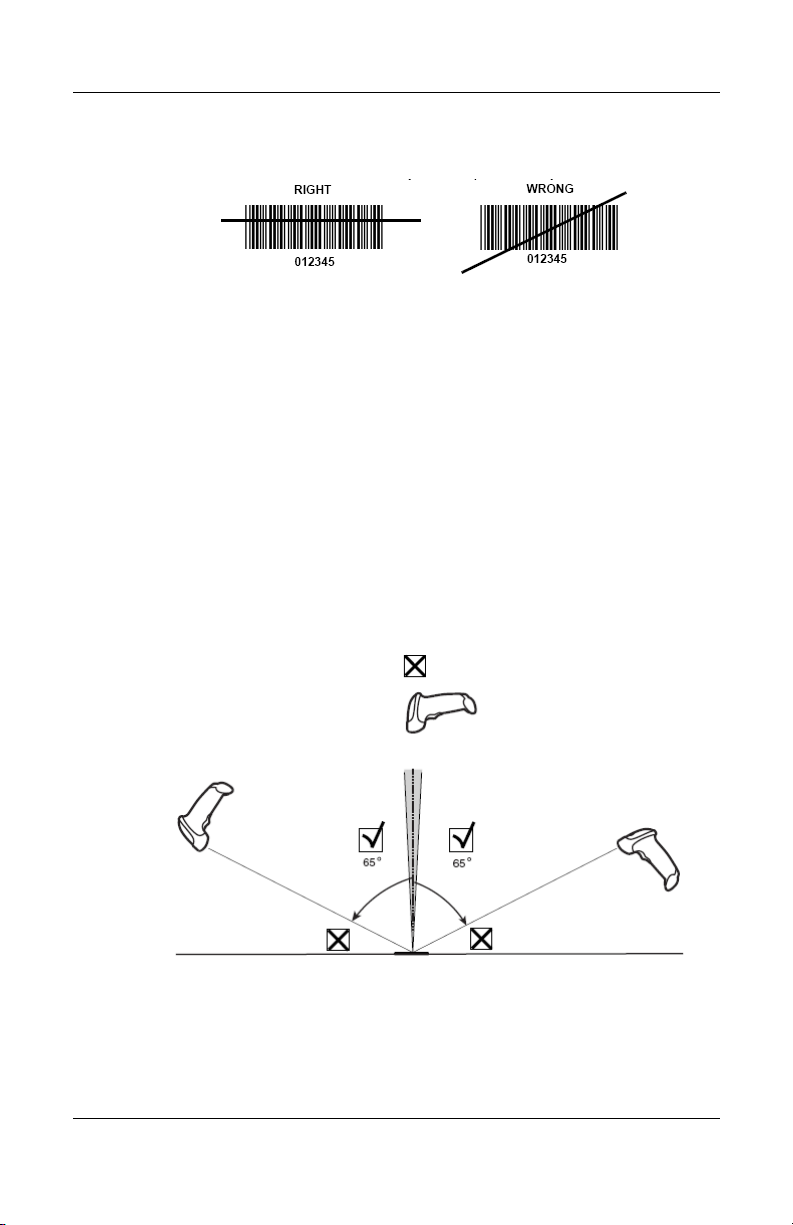
3. Ensure the scan line crosses every bar and space of the
symbol.
4–4 www.hp.com User Guide
Page 43
4. Upon successful decode, the scanner beeps and the LED
turns green.
Aiming the Scanner
Do not hold the scanner directly over the bar code. Laser light
reflecting directly back into the scanner from the bar code is
known as specular reflection. This specular reflection can make
decoding difficult. You can tilt the scanner up to 55° forward or
back and achieve a successful decode. Simple practice quickly
shows what tolerances to work within.
Operating the Scanner
User Guide www.hp.com 4–5
Page 44

Operating the Scanner
Scanning in Hands-Free Mode
When the scanner is seated in the stand’s “cup,” the scanner’s
built-in sensor places the scanner in hands-free mode. When the
scanner is removed from the stand it operates in its normal
hand-held mode.
1. Ensure all cable connections are secure.
2. Insert the scanner in the stand by placing the front of the
scanner into the stand’s “cup.”
3. To scan a bar code, place the bar code up to the scanner and
ensure the scan line crosses every bar and space of the
symbol.
4. Upon successful decode, the scanner beeps and the LED
turns green.
4–6 www.hp.com User Guide
Page 45

5
Programming User Preferences
You have the option to program the scanner to perform various
functions, or activate different features. This chapter describes
each user preference feature and provides the programming bar
codes necessary for selecting these features for your scanner.
The scanner is shipped with the settings listed in the “User
Preferences Default” table in this chapter (also see the section
“USB Default Parameters” in chapter 3 of this guide). If the
default values suit your requirements, programming may not be
necessary.
Features values are set by scanning single bar codes or short bar
code sequences. The settings are stored in non-volatile memory
and are preserved even when the scanner is powered down.
To return all features to their default values, all you need to do is
scan the Set All Defaults bar code.
Throughout the programming bar code menus, default values are
✎
indicated with asterisks (*).
Scanning Sequence Examples
In most cases you need only scan one bar code to set a specific
parameter value. For example, if you want to set the beeper tone
to high, simply scan the High Frequency (beeper tone) bar code
listed under Beeper Tone. The scanner issues a fast warble beep
and the LED turns green, signifying a successful parameter entry.
Other parameters, such as specifying Serial Response Time-Out
User Guide www.hp.com 5–1
Page 46

Programming User Preferences
or setting Data Transmission Formats, require that you scan
several bar codes. Refer to “Laser On Time” in this chapter and
“Scan Data Transmission Format” in the Programming Reference
Guide on the software and documentation CD for descriptions of
this procedure.
Errors While Scanning
Unless otherwise specified, if you make an error during a
scanning sequence, just re-scan the correct parameter.
User Preferences Default Parameters
The following table lists the defaults for user preferences
parameters. If you want to change any option, scan the
appropriate bar code(s) provided in the “User Preferences”
section of this chapter.
User Preferences Default
Parameter Default
Set Default Parameter All Defaults
Beeper Tone Medium
Beeper Volume High
Power Mode Continuous On
Laser On Time 3.0 Sec.
Beep After Good Decode Enable
5–2 www.hp.com User Guide
Page 47

User Preferences
Set Default Parameter
Scanning this bar code returns all parameters to the default values
listed in Chapter 5, “Standard Default Parameters” of the
Programming Reference Guide on the software and
documentation CD.
Set All Defaults
Programming User Preferences
User Guide www.hp.com 5–3
Page 48

Programming User Preferences
Beeper Tone
To select a decode beep frequency (tone), scan the Low
Frequency, Medium Frequency, or High Frequency bar code.
Low Frequency
*Medium Frequency
(Optimum Settings)
High Frequency
5–4 www.hp.com User Guide
Page 49

Beeper Volume
To select a beeper volume, scan the Low Volume, Medium
Volume, or High Volume bar code.
Programming User Preferences
Low Volume
Medium Volume
*High Volume
User Guide www.hp.com 5–5
Page 50

Programming User Preferences
Power Mode
This parameter determines whether or not power remains on after
a decode attempt. When in reduced power mode, the scanner
enters into a low power consumption mode to preserve battery
life after each decode attempt. When in continuous power mode,
power remains on after each decode attempt.
*Continuous On
Reduced Power Mode
5–6 www.hp.com User Guide
Page 51

Laser On Time
This parameter sets the maximum time that decode processing
continues during a scan attempt. It is programmable in 0.1 second
increments from 0.5 to 9.9 seconds. The default Laser On Time
is 3.0 seconds.
To set a Laser On Time, scan the bar code below. Next, scan two
numeric bar codes in Chapter 8, “Numeric Bar Codes,” of the
Programming Reference Guide, that correspond to the desired on
time. Single digit numbers must have a leading zero. For
example, to set an On Time of 0.5 seconds, scan the bar code
below, then scan the “0” and “5” bar codes. If you make an error,
or wish to change your selection, scan Cancel.
Programming User Preferences
Laser On Time
User Guide www.hp.com 5–7
Page 52

Programming User Preferences
Beep After Good Decode
Scan a bar code below to select whether or not the scanner beeps
after a good decode. If Do Not Beep After Good Decode is
selected, the beeper still operates during parameter menu
scanning and indicates error conditions.
*Beep After Good Decode
(Enable)
Do Not Beep After Good Decode
(Disable)
5–8 www.hp.com User Guide
Page 53

Troubleshooting
Solving Common Problems
The following table lists possible problems, the possible cause of
each problem, and the recommended solutions.
Problem Possible Cause Solution
A
Nothing happens
when you follow the
operating
instructions, or the
scanner displays
erratic behavior
(laser does not come
on, scanner emits
frequent beeps).
Laser comes on, but
barcode symbol
does not decode.
No power to the
scanner.
Interface/power
cables are loose.
Scanner is not
programmed for the
correct bar code type.
Bar code symbol is
unreadable.
Distance between
scanner and bar code
is incorrect.
Check the system power.
Check for loose cable connections.
Be sure the scanner is programmed
to read the type of bar code you
are scanning.
Check the symbol to make sure it is
not defaced. Try scanning test
symbols of the same bar code type.
Move the scanner closer to or
further from the bar code.
User Guide www.hp.com A–1
Page 54

Troubleshooting
Problem Possible Cause Solution
Symbol is decoded,
but not transmitted
to the host.
Scanned data is
incorrectly displayed
on the host.
Scanner is not
programmed for the
correct host type.
Scanner is not
programmed to work
with the host. Check
scanner host type
parameters or editing
options.
Scan the appropriate host type bar
code.
Be sure the USB host is selected.
Ensure that the POS system is
programmed for the correct
keyboard type and language, and
the Caps Lock key is in the correct
state.
Be sure editing options found in the
Programming Reference Guide on
the Point of Sale System Software
and Documentation CD (e.g., ADF,
UPCE to UPC-A Conversion) are
properly programmed.
Using the Worldwide Web
For the online access to technical support information, self-solve
tools, online assistance, community forums or IT experts, broad
multivendor knowledge base, monitoring and diagnostic tools, go
to http://www.hp.com/support.
Preparing to Call Technical Support
If you can not solve a problem using the troubleshooting tips in
this section, you may need to call technical support. Refer to the
Support Telephone Numbers guide on the Point of Sale System
Software and Documentation CD. Have the following
information available when you call:
■ Barcode Scanner model number
■ Serial number for the scanner
A–2 www.hp.com User Guide
Page 55

■ Purchase date on invoice
■ Condition under which the problem occurred
■ Error messages received
■ Hardware configuration
■ Hardware and software you are using
Troubleshooting
User Guide www.hp.com A–3
Page 56

Troubleshooting
A–4 www.hp.com User Guide
Page 57

Technical Specifications
HP USB Barcode Scanner
Power Requirements Decoded: 5 VDC +/- 10% @
approximately 200mA (nominal)
Stand-By Current 500mA (max)
Power Source Depending on USB host:
Hosted powered converts a 9 Volt
battery to a 5 Volt battery
Decode Capability Decoded:
UPC/EAN, UPC/EAN with
supplementals, UCC/EAN, JAN 8
& 13, 128, Code 39, Code 39 Full
ASCII, Code 39 Trioptic, Codabar
(NW7), Interleaved 2 of 5, Discrete
2 of 5, Code 128, Code 93, MSI,
Code 11, UCC/EAN RSS, Code 32,
Coupon Code, Bookland EAN,
1ATA, and RSS.
B
Beeper Operation User-selectable: Enable, Disable
Beeper Volume User-selectable: three levels
Beeper Tone User-selectable: three tones
Scan Repetition Rate 100 +/- 5 scans/seconds
Yaw Tolerance +/- 10
User Guide www.hp.com B–1
o
from nominal
Page 58

Technical Specifications
HP USB Barcode Scanner
Pitch Tolerance +/- 65o from nominal
Roll Tolerance +/- 60
Print Contrast Minimum 25% minimum reflectance
Ambient Light Immunity
• Indoor
• Outdoor
Durability 5 ft. (1.5 m) drops to concrete
Operating Temperature 32
Storage Temperature -40
Humidity 5% to 95% (non-condensing)
Weight (without cable) 5.15 oz. (146 g)
o
from nominal
differential, measure at 650 nm.
450 ft. candles (4,842 Lux)
10,000 ft. candles (107, 600 Lux)
o
to 120o F (0o to 50o C)
o
to 140o F (-40o to 60o C)
Dimensions:
Weight
Width
Depth
Laser 650 nm laser diode
Laser Classifications IEC 825-1 Class 2
ESD 15 k V a r ea d i sc h a r ge
Minimum Element Width 5 mil (0.127 mm)
Interfaces Supported Decoded: USB
Electrical Safety Certified Pending to UL1950, CSA
B–2 www.hp.com User Guide
6.0 in (15.2 cm)
2.5 in (6.3 cm)
3.34 in (8.4 cm)
8 kV contact discharge
C22.2 No. 950 EN60950/IC950
Page 59
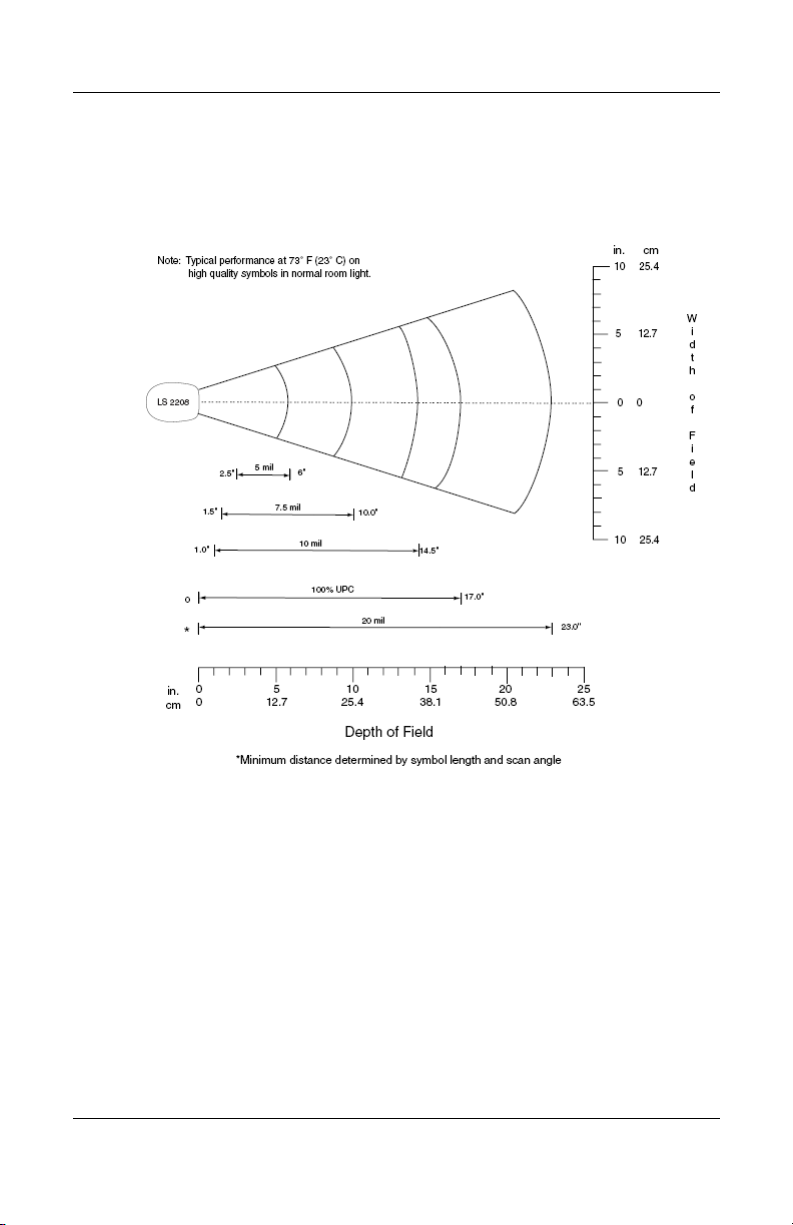
Decode Zone
Technical Specifications
User Guide www.hp.com B–3
Page 60

Technical Specifications
Disposal of Waste Equipment by Users in Private Household in the European Union
This symbol on the product or on its
packaging indicates that this product must not
be disposed of with your other household
waste. Instead, it is your responsibility to
dispose of your waste equipment by handing it
over to a designated collection point for the
recycling of waste electrical and electronic
equipment. The separate collection and
recycling of your waste equipment at the time
of disposal will help to conserve natural resources and ensure that
it is recycled in a manner that protects human health and the
environment. For more information about where you can drop off
your waste equipment for recycling, please contact your local city
office, your household waste disposal service or the shop where
you purchased the product.
B–4 www.hp.com User Guide
 Loading...