

HP ProLiant DX170r G10 User Manual

HPE ProLiant DX170r Gen10 Server User Guide
Abstract
This document is for the person who installs, administers, and troubleshoots servers and
storage systems. Hewlett Packard Enterprise assumes you are qualified in the servicing of
computer equipment and trained in recognizing hazards in products with hazardous energy
levels.
Part Number: P19001-001
Published: July 2019
Edition: 1

©
Copyright 2019 Hewlett Packard Enterprise Development LP
Notices
The information contained herein is subject to change without notice. The only warranties for Hewlett
Packard Enterprise products and services are set forth in the express warranty statements accompanying
such products and services. Nothing herein should be construed as constituting an additional warranty.
Hewlett Packard Enterprise shall not be liable for technical or editorial errors or omissions contained
herein.
Confidential computer software. Valid license from Hewlett Packard Enterprise required for possession,
use, or copying. Consistent with FAR 12.211 and 12.212, Commercial Computer Software, Computer
Software Documentation, and Technical Data for Commercial Items are licensed to the U.S. Government
under vendor's standard commercial license.
Links to third-party websites take you outside the Hewlett Packard Enterprise website. Hewlett Packard
Enterprise has no control over and is not responsible for information outside the Hewlett Packard
Enterprise website.
Acknowledgments
Intel® and Xeon® are trademarks of Intel Corporation in the U.S. and other countries.
Microsoft®, Windows®, and Windows Server® are either registered trademarks or trademarks of Microsoft
Corporation in the United States and/or other countries.
Linux® is the registered trademark of Linus Torvalds in the U.S. and other countries.
Red Hat® Enterprise Linux® are registered trademarks of Red Hat, Inc. in the United States and other
countries.
VMware® ESXi™ and VMware vSphere® are registered trademarks or trademarks of VMware, Inc. in the
United States and/or other jurisdictions.
microSD is a trademark or a registered trademark of SD-3D in the United States, other countries of both.

Contents
HPE Apollo DX2000 Gen10 System.......................................................7
Component identification.......................................................................8
Rear panel components................................................................................................................8
Serial number/iLO information pull tab...............................................................................8
Rear panel LEDs and buttons.......................................................................................................9
Server UID LED................................................................................................................10
UID button functionality.................................................................................................... 10
Front panel LED power fault codes..................................................................................10
System board components..........................................................................................................11
System maintenance switch descriptions........................................................................ 12
DIMM label identification.................................................................................................. 12
Processor, heatsink, and socket components..................................................................14
Bayonet port numbering..............................................................................................................15
PCIe riser board components..................................................................................................... 15
Primary riser board components...................................................................................... 15
Secondary riser board components................................................................................. 16
Operations............................................................................................. 19
Power up the server....................................................................................................................19
Power down the server............................................................................................................... 19
Remove the server from the chassis.......................................................................................... 19
Install the server into the chassis................................................................................................20
Remove the air baffle..................................................................................................................21
Install the air baffle......................................................................................................................22
Remove the bayonet board.........................................................................................................22
Remove the secondary riser blank............................................................................................. 24
Install the bayonet board.............................................................................................................25
Install the secondary riser blank................................................................................................. 26
Remove the secondary riser cage.............................................................................................. 27
Install the secondary riser cage.................................................................................................. 28
Remove the primary riser cage...................................................................................................29
Install the primary riser cage.......................................................................................................30
Remove the primary riser blank.................................................................................................. 30
Install the primary riser blank...................................................................................................... 31
Setup...................................................................................................... 33
General site planning.................................................................................................................. 33
Optional service.......................................................................................................................... 33
Product QuickSpecs................................................................................................................... 33
Compiling the documentation..................................................................................................... 33
Initial system installation............................................................................................................. 34
HPE Installation Service...................................................................................................34
Setting up the server........................................................................................................ 34
Operational requirements........................................................................................................... 37
Site requirements............................................................................................................. 37
3

Space and airflow requirements.......................................................................................37
Temperature requirements...............................................................................................37
Power requirements......................................................................................................... 38
Grounding requirements.................................................................................................. 38
Device bay thermal requirements.................................................................................... 38
Server warnings and cautions.....................................................................................................38
Electrostatic discharge................................................................................................................40
POST screen options..................................................................................................................40
Hardware options installation..............................................................41
Introduction................................................................................................................................. 41
SUV cable option........................................................................................................................ 41
Using an SUV cable for a KVM setup.............................................................................. 41
Using an SUV cable to access USB drives in a KVM setup............................................ 42
Processor heatsink assembly option.......................................................................................... 42
Installing the processor heatsink assembly......................................................................42
Processor cautions...........................................................................................................43
Install the processor heatsink assembly.......................................................................... 43
Selecting an advanced fan cooling method..................................................................... 45
Memory options...........................................................................................................................45
DIMM population information........................................................................................... 46
DIMM-processor compatibility..........................................................................................46
HPE SmartMemory speed information.............................................................................46
Installing a DIMM..............................................................................................................46
Riser cage options...................................................................................................................... 47
Installing the primary riser cage option............................................................................ 47
Installing the secondary riser cage option........................................................................48
Expansion board options............................................................................................................ 49
Installing an expansion board in the primary riser cage...................................................49
Installing an expansion board in the secondary riser cage.............................................. 52
Storage controller options........................................................................................................... 54
Installing a Smart Array type-p controller in the primary riser cage................................. 54
Installing a Smart Array type-p controller in the secondary riser cage.............................58
Configuring an HPE Smart Array Gen10 controller..........................................................61
M.2 SATA SSD option................................................................................................................. 61
Installing an M.2 SSD.......................................................................................................62
FlexibleLOM option..................................................................................................................... 63
Installing the FlexibleLOM adapter...................................................................................64
Installing the Omni-Path Architecture adapter option................................................................. 65
Installing the Media Module adapter........................................................................................... 68
HPE Trusted Platform Module 2.0 Gen10 option........................................................................70
Overview.......................................................................................................................... 70
HPE Trusted Platform Module 2.0 Guidelines..................................................................71
Installing and enabling the HPE TPM 2.0 Gen10 Kit....................................................... 72
Cabling................................................................................................... 76
Cabling guidelines.......................................................................................................................76
Smart Array cabling.....................................................................................................................77
Onboard S100i SR Gen10 controller cabling (SATA only)............................................... 77
Smart Array type-p controller cabling (SAS/SATA).......................................................... 78
Storage controller backup power cabling......................................................................... 79
Secondary riser cabling.............................................................................................................. 80
OPA adapter cabling................................................................................................................... 80
4

Software and configuration utilities.................................................... 81
Server mode................................................................................................................................81
All Nutanix product documentation............................................................................................. 81
Product QuickSpecs................................................................................................................... 81
Active Health System Viewer......................................................................................................81
Active Health System....................................................................................................... 82
HPE iLO 5................................................................................................................................... 83
iLO Federation..................................................................................................................83
iLO Service Port............................................................................................................... 83
iLO RESTful API...............................................................................................................84
RESTful Interface Tool..................................................................................................... 84
iLO Amplifier Pack............................................................................................................84
HPE Apollo Platform Manager overview.....................................................................................85
HPE Insight Cluster Management Utility.....................................................................................85
Integrated Management Log.......................................................................................................86
Intelligent Provisioning................................................................................................................ 86
Intelligent Provisioning operation..................................................................................... 86
Management Security................................................................................................................. 87
Scripting Toolkit for Windows and Linux..................................................................................... 87
UEFI System Utilities.................................................................................................................. 88
Selecting the boot mode ................................................................................................. 88
Secure Boot......................................................................................................................89
Launching the Embedded UEFI Shell ............................................................................. 89
HPE Smart Storage Administrator.............................................................................................. 90
HPE MR Storage Administrator.................................................................................................. 91
HPE InfoSight for servers .......................................................................................................... 91
StorCLI........................................................................................................................................91
USB support................................................................................................................................92
External USB functionality................................................................................................92
Redundant ROM support............................................................................................................ 92
Safety and security benefits............................................................................................. 92
Keeping the system current........................................................................................................ 92
Updating firmware or system ROM.................................................................................. 92
Drivers..............................................................................................................................95
Software and firmware..................................................................................................... 95
Operating system version support................................................................................... 95
HPE Pointnext Portfolio....................................................................................................95
Proactive notifications...................................................................................................... 96
Troubleshooting.................................................................................... 97
NMI functionality..........................................................................................................................97
Troubleshooting resources..........................................................................................................97
System battery replacement................................................................ 98
System battery information......................................................................................................... 98
Removing and replacing the system battery...............................................................................98
Safety, warranty, and regulatory information................................... 100
Regulatory information..............................................................................................................100
Notices for Eurasian Economic Union............................................................................100
Turkey RoHS material content declaration.....................................................................101
5

Ukraine RoHS material content declaration................................................................... 101
Warranty information.................................................................................................................101
Specifications......................................................................................102
Environmental specifications.................................................................................................... 102
Mechanical specifications......................................................................................................... 102
Temperature requirements........................................................................................................102
List of components with temperature requirements.................................................................. 103
Thermal limitations for components in systems with the Enhanced Processor
Performance feature enabled.........................................................................................103
Thermal limitations for components in systems with the Enhanced Processor
Performance feature disabled........................................................................................ 116
Websites.............................................................................................. 130
Support and other resources.............................................................131
Accessing Hewlett Packard Enterprise Support....................................................................... 131
Accessing updates....................................................................................................................131
Customer self repair..................................................................................................................132
Remote support........................................................................................................................ 132
Documentation feedback.......................................................................................................... 132
6

HPE Apollo DX2000 Gen10 System
The HPE Apollo DX2000 Gen10 System is a dense, multiserver platform that packs incredible
performance and workload flexibility into a small data center space. It is designed to provide a bridge to
scale out architecture for traditional data centers.
The following chassis and server models are available:
Chassis
• HPE Apollo DX2200 Gen10 Chassis with 12 LFF drives
• HPE Apollo DX2600 Gen10 Chassis with 24 SFF drives
HPE Apollo DX2600 Gen10 Chassis with 16 SFF + 8 NVMe drives
• HPE Apollo DX2800 Gen10 Chassis with 16 NVMe drives
• HPE Apollo DX2800 Gen10 Chassis with 24 SFF drives
Server nodes
• HPE ProLiant DX170r Gen10 Server – 1U server node
• HPE ProLiant DX190r Gen10 Server – 2U server node
The following server combinations are supported:
• Four 1U servers
• Two 1U servers and one 2U server
• Two 2U servers
For more information about product features, specifications, options, configurations, and compatibility, see
the product QuickSpecs on the Hewlett Packard Enterprise website (
http://www.hpe.com/info/qs).
HPE Apollo DX2000 Gen10 System 7
Component identification
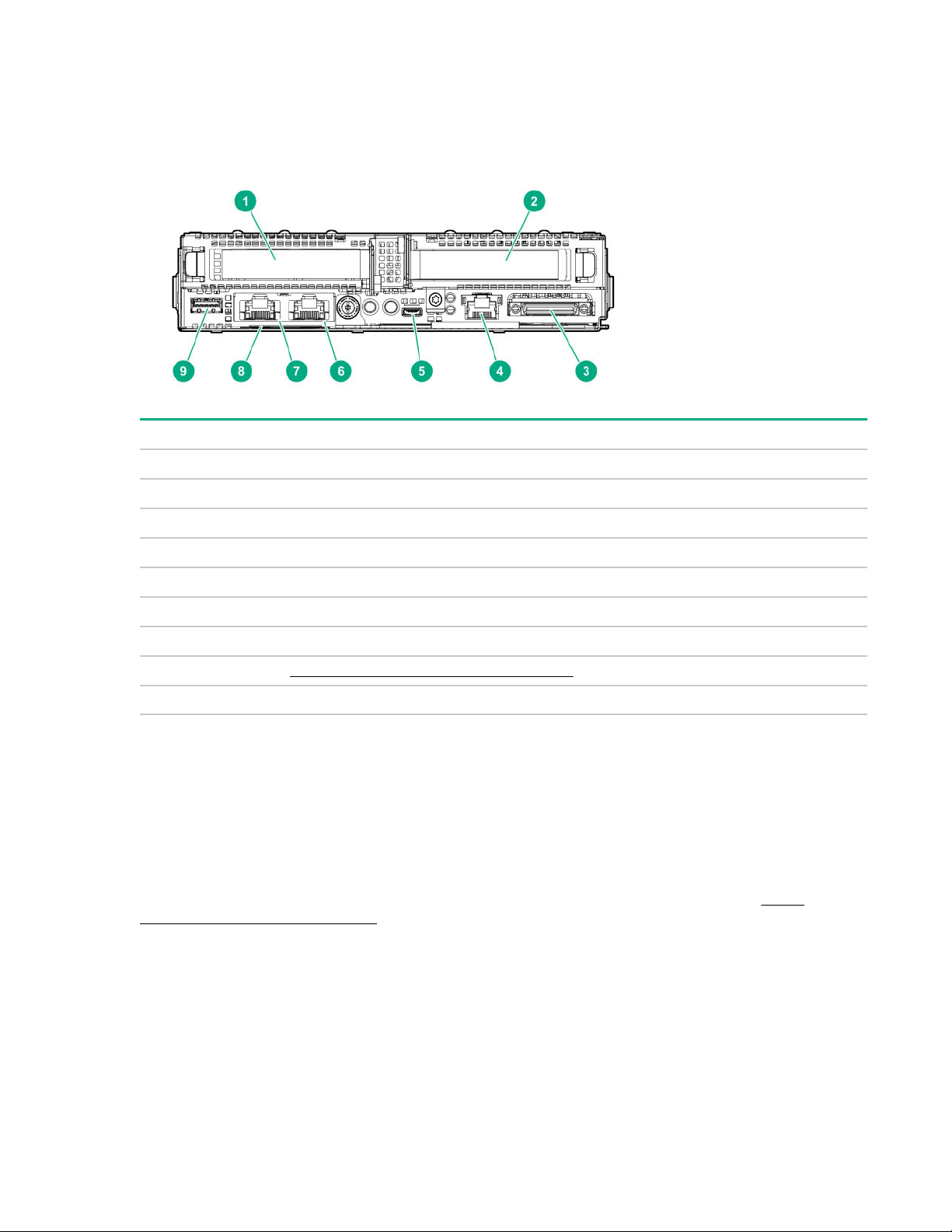
Rear panel components
Item Description
1 Slot 1 PCIe3 x16 (16, 8, 4, 1)
2 Slot 2 PCIe3 x16 (16, 8, 4, 1) or FlexibleLOM
3 SUV port
4 iLO Management Port
1
5 iLO Service Port
6 Media Module NIC port 2
7 Media Module NIC port 1
8 Serial number/iLO information pull tab on page 8
9 USB 3.0 port
1
If the RCM module is installed on the chassis, the iLO Management Port is automatically disabled.
2
The Media Module adapter is a hardware option.
2
2
Serial number/iLO information pull tab
The serial number/iLO information pull tab is double-sided. One side shows the server serial number and
the customer asset tag label. The other side shows the default iLO account information and QR code
label.
Use a mobile device to scan the QR code label to display the server mobile product page (http://
www.hpe.com/qref/dx170rgen10). This page contains links to server setup information, spare part
numbers, QuickSpecs, troubleshooting resources, and other useful product links.
8 Component identification

Rear panel LEDs and buttons
Item Description Status Definition
1 NIC link LED
2
Green Linked to network
Off No network link
2 NIC status LED
1
Flashing green Network active
Off No network activity
3 Health LED
1
Solid green Normal
Flashing green iLO is rebooting.
Flashing amber System degraded
Flashing red System critical
4 Do not remove LED Flashing white Do not remove the server.
Removing the server may
terminate the current operation
and cause data loss.
Off The server can be removed.
5 UID button/LED
1
Solid blue Activated
Table Continued
Component identification 9

Item Description Status Definition
Flashing blue • 1 flash per second = Remote
management or firmware
upgrade in progress
• 4 flashes per second = iLO
manual soft reboot sequence
initiated
• 8 flashes per second = iLO
manual hard reboot sequence
in progress
Off Deactivated
6 Power On/Standby button
and system power LED
1
When the LEDs described in this table flash simultaneously, a power fault has occurred. For more information, see
Front panel LED power fault codes on page 10.
2
If the health LED indicates a degraded or critical state, review the system IML or use iLO to review the system health
status.
3
Facility power is not present, power cord is not attached, no power supplies are installed, power supply failure has
occurred, or the front I/O cable is disconnected.
Server UID LED
The UID LED is used to locate a particular server when it is deployed in a dense chassis with other
equipment. Activating the UID LED helps an onsite technician to quickly identify a server for maintenance
tasks.
UID button functionality
The UID button can be used to display the Server Health Summary when the server will not power on.
For more information, see the latest HPE iLO 5 User Guide on the Hewlett Packard Enterprise website.
Solid green System on and normal operation
1
Flashing green Performing power-on sequence
Solid amber System in standby
Off No power present
3
Front panel LED power fault codes
The following table provides a list of power fault codes, and the subsystems that are affected. Not all
power faults are used by all servers.
Subsystem LED behavior
System board 1 flash
Processor 2 flashes
Memory 3 flashes
Riser board PCIe slots 4 flashes
10 Component identification
Table Continued
Subsystem LED behavior
FlexibleLOM 5 flashes
Removable HPE Smart Array SR Gen10 controller 6 flashes
System board PCIe slots 7 flashes
Power backplane or storage backplane 8 flashes
Power supply 9 flashes
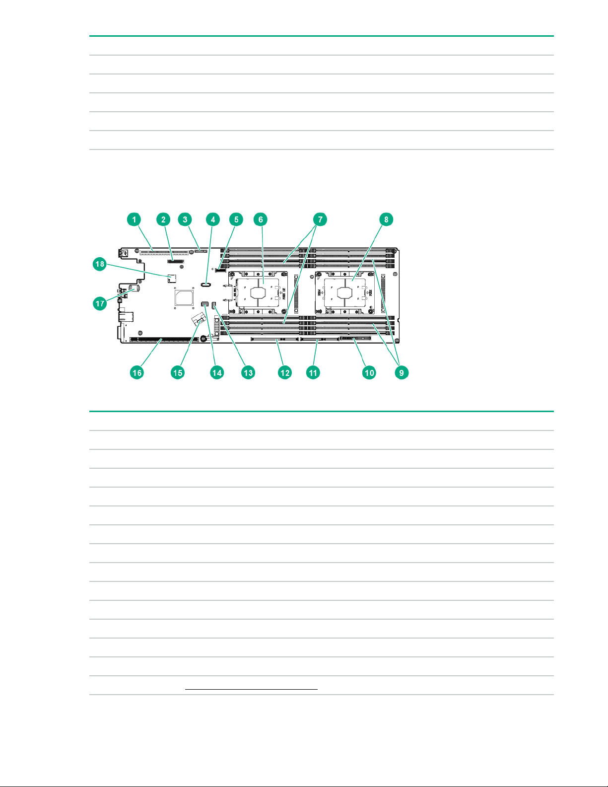
System board components
Item Description
1 Primary PCIe x16 riser connector 1
2 Media Module connector
3 System battery
4 OPA adapter sideband cable connector
5 M.2 SSD riser connector
6 Processor 1
7 DIMM slots for processor 1
8 Processor 2
9 DIMM slots for processor 2
10 Bayonet board connector
11 Secondary PCIe x24 riser connector 4
12 Secondary PCIe x24 riser connector 3
13 x4 SATA port
14 System maintenance switch
Table Continued
Component identification 11

Item Description
15 x8 SATA port
16 Secondary PCIe x24 riser connector 2
17 TPM connector
18 microSD slot
System maintenance switch descriptions
Position Default Function
1
S1
S2 Off Reserved
S3 Off Reserved
S4 Off Reserved
1
S5
Off
Off
Off = iLO 5 security is enabled.
On = iLO 5 security is disabled.
Off = Power-on password is enabled.
On = Power-on password is disabled.
S61, 2,
3
Off
S7 Off Reserved
S8 — Reserved
S9 — Reserved
S10 — Reserved
S11 — Reserved
S12 — Reserved
1
To access the redundant ROM, set S1, S5, and S6 to On.
2
When the system maintenance switch position 6 is set to the On position, the system is prepared to restore all
configuration settings to their manufacturing defaults.
3
When the system maintenance switch position 6 is set to the On position and Secure Boot is enabled, some
configurations cannot be restored. For more information, see Secure Boot on page 89.
DIMM label identification
To determine DIMM characteristics, see the label attached to the DIMM. The information in this section
helps you to use the label to locate specific information about the DIMM.
Off = No function
On = Restore default manufacturing settings
12 Component identification
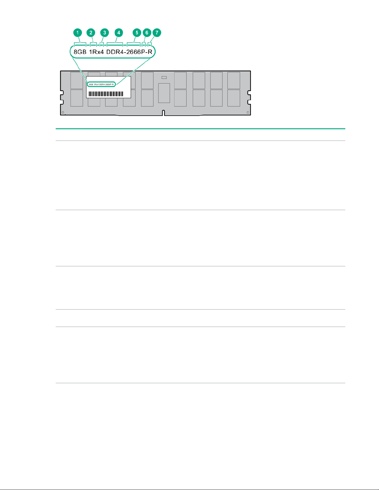
Item Description Example
1 Capacity
2 Rank
3 Data width on DRAM
4 Memory generation
8 GB
16 GB
32 GB
64 GB
128 GB
1R = Single rank
2R = Dual rank
4R = Quad rank
8R = Octal rank
x4 = 4-bit
x8 = 8-bit
x16 = 16-bit
PC4 = DDR4
5 Maximum memory speed
2133 MT/s
2400 MT/s
2666 MT/s
2933 MT/s
Table Continued
Component identification 13
Item Description Example
6 CAS latency
7 DIMM type
For more information about product features, specifications, options, configurations, and compatibility, see
the HPE DDR4 SmartMemory QuickSpecs on the Hewlett Packard Enterprise website (http://
www.hpe.com/support/DDR4SmartMemoryQS).
P = CAS 15-15-15
T = CAS 17-17-17
U = CAS 20-18-18
V = CAS 19-19-19 (for RDIMM, LRDIMM)
V = CAS 22-19-19 (for 3DS TSV LRDIMM)
Y = CAS 21-21-21 (for RDIMM, LRDIMM)
Y = CAS 24-21-21 (for 3DS TSV LRDIMM)
R = RDIMM (registered)
L = LRDIMM (load reduced)
E = Unbuffered ECC (UDIMM)
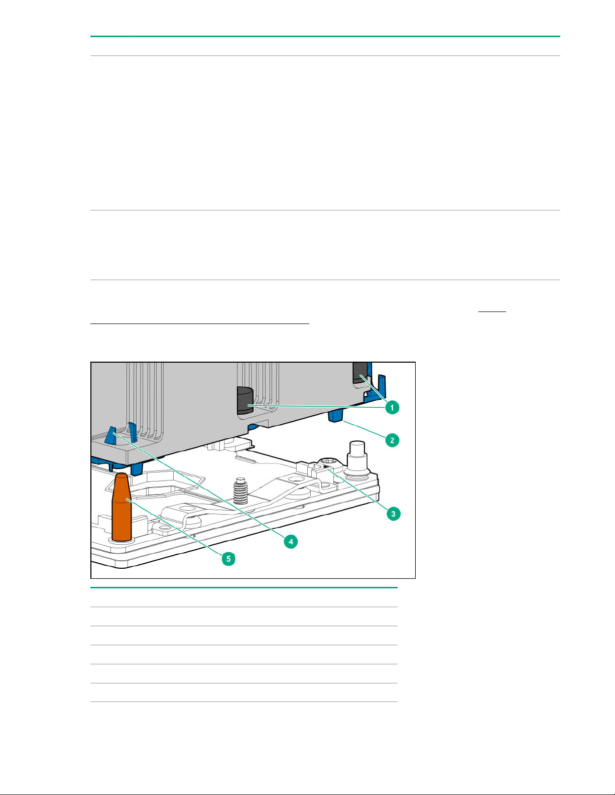
Processor, heatsink, and socket components
Item Description
1 Heatsink nuts
2 Processor carrier
3 Pin 1 indicator
4 Heatsink latch
5 Alignment post
14 Component identification
1
1
Symbol also on the processor and frame.
Bayonet port numbering
PCIe riser board components
This section identifies the riser slots compatible with specific types of expansion options supported by the
server. The following riser options are supported:
Primary riser
•
• Secondary risers
• M.2 SSD riser
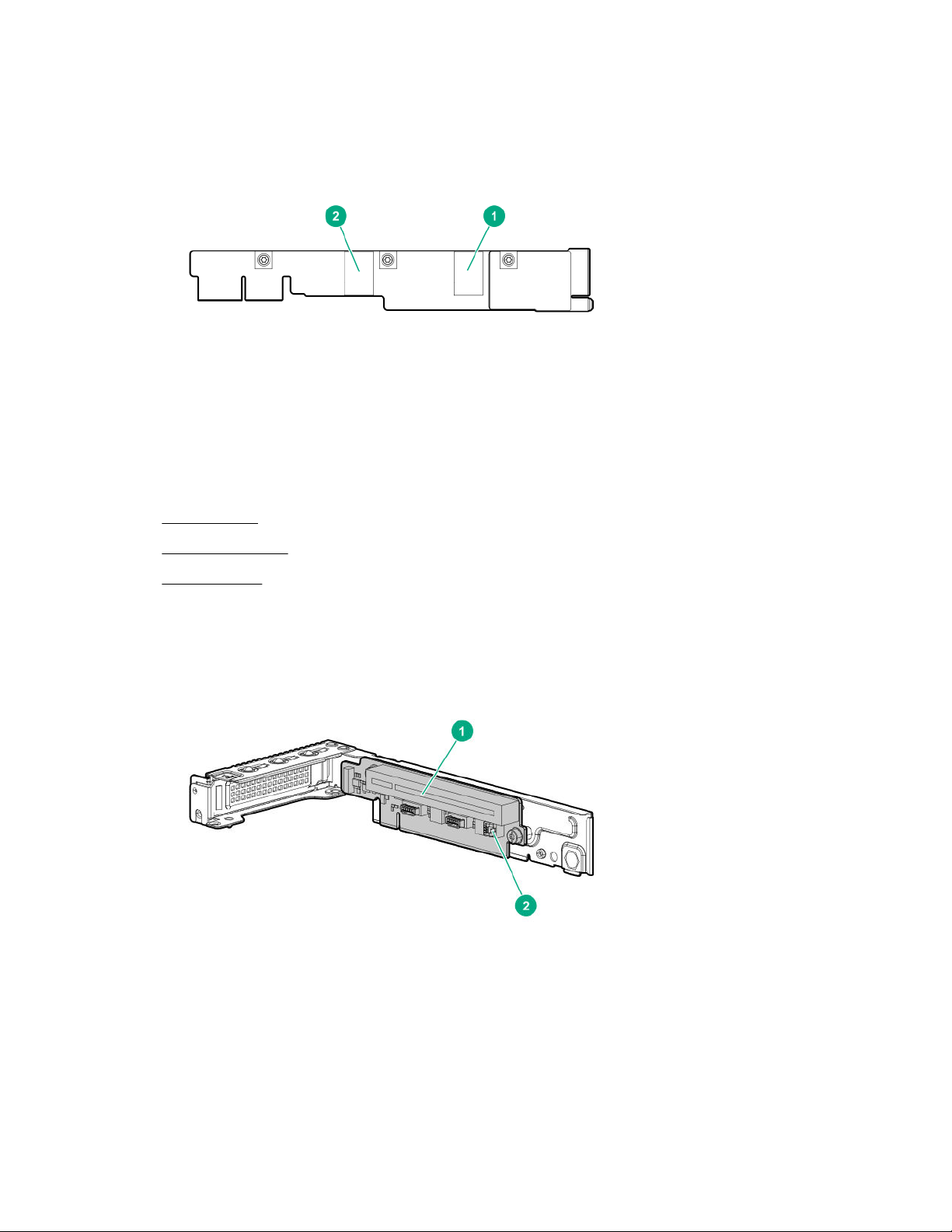
Primary riser board components
The primary riser function is linked to processor 1. This riser only supports low-profile expansion boards.
Component identification 15

Item Slot number Description Supported option
1 1 PCIe3 x16 (16, 8, 4, 1) • Smart Array type-p controller
• Network adapter
• OPA adapter
1
2 — Storage controller backup power
connector
1
Intel Omni-Path Architecture
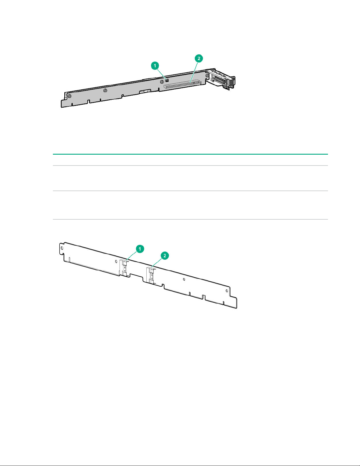
Secondary riser board components
The server supports multiple riser options in the secondary position.
P1 secondary riser board components
—
Item Slot
number
1 — Storage controller backup power
2 2 PCIe3 x16 (16, 8, 4, 1) • Smart Array type-p controller
Description Supported options
connector
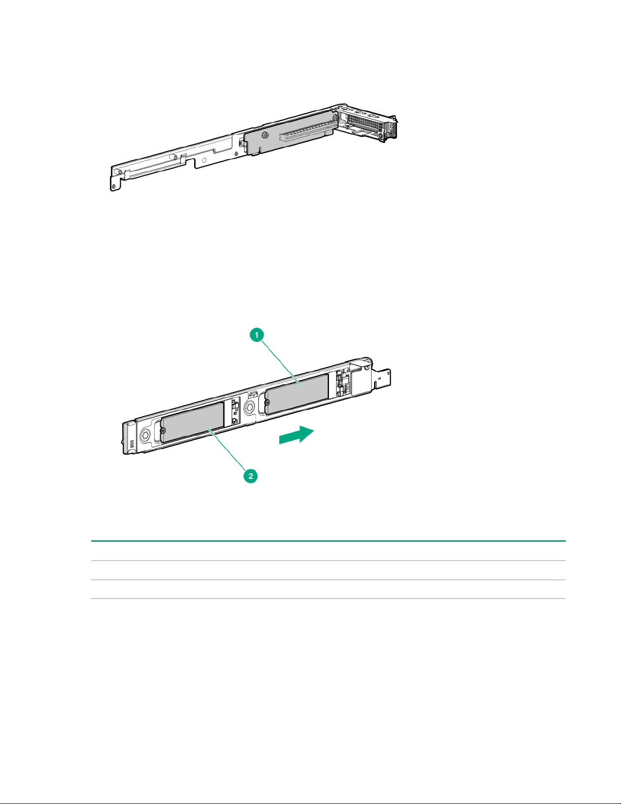
P2 secondary riser board components
Processor 2 is required to support the P2 secondary riser option.
—
• Low-profile expansion boards
16 Component identification
Item Slot number Description Supported options
1 — Storage controller
2 2 PCIe3 x16 (16, 8, 4, 1) • Smart Array type-p controller
P1/P2 secondary riser port numbering
FlexibleLOM riser board slot
The FlexibleLOM riser function is linked to processor 1.
—
backup power
connector
• Low-profile expansion boards
Component identification 17
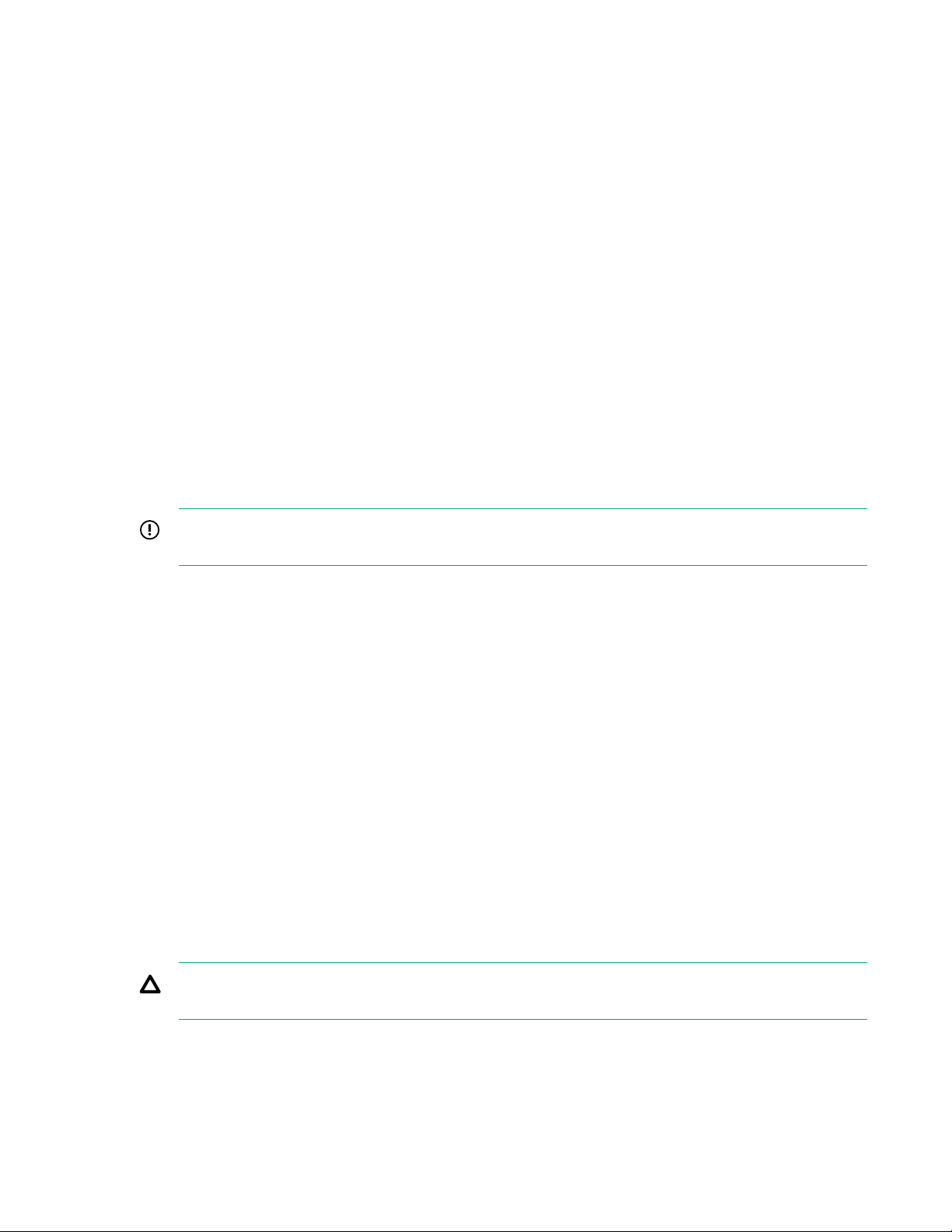
M.2 SSD riser bay numbering
The arrow points toward the server release lever.
Item Description
1 Bay 7
2 Bay 8
18 Component identification
Operations
This chapter describes the hardware operations carried out prior to and after installing or removing a
hardware option, or performing a server maintenance or troubleshooting procedure.
Before performing these hardware operations, review and observe the server warnings and cautions.
Power up the server
The DX chassis firmware initiates an automatic power-up sequence when the servers are installed. If the
default setting is changed, use one of the following methods to power up each server:
• Use a virtual power button selection through iLO 5.
• Press and release the Power On/Standby button.
When the server goes from standby mode to full power mode, the server power LED changes from amber
to green.
Power down the server
Before powering down the server for any upgrade or maintenance procedures, perform a backup of
critical server data and programs.
IMPORTANT: When the server is in standby mode, auxiliary power is still being provided to the
system.
To power down the server, use one of the following methods:
• Press and release the Power On/Standby button.
This method initiates a controlled shutdown of applications and the OS before the server enters
standby mode.
• Press and hold the Power On/Standby button for more than 4 seconds to force the server to enter
standby mode.
This method forces the server to enter standby mode without properly exiting applications and the OS.
If an application stops responding, you can use this method to force a shutdown.
• Use a virtual power button selection through iLO 5.
This method initiates a controlled remote shutdown of applications and the OS before the server
enters standby mode.
Before proceeding, verify that the server is in standby mode by observing that the system power LED is
amber.
Remove the server from the chassis
CAUTION: To prevent improper cooling and thermal damage, do not operate the chassis unless all
bays are populated with a component or a blank.
Operations 19
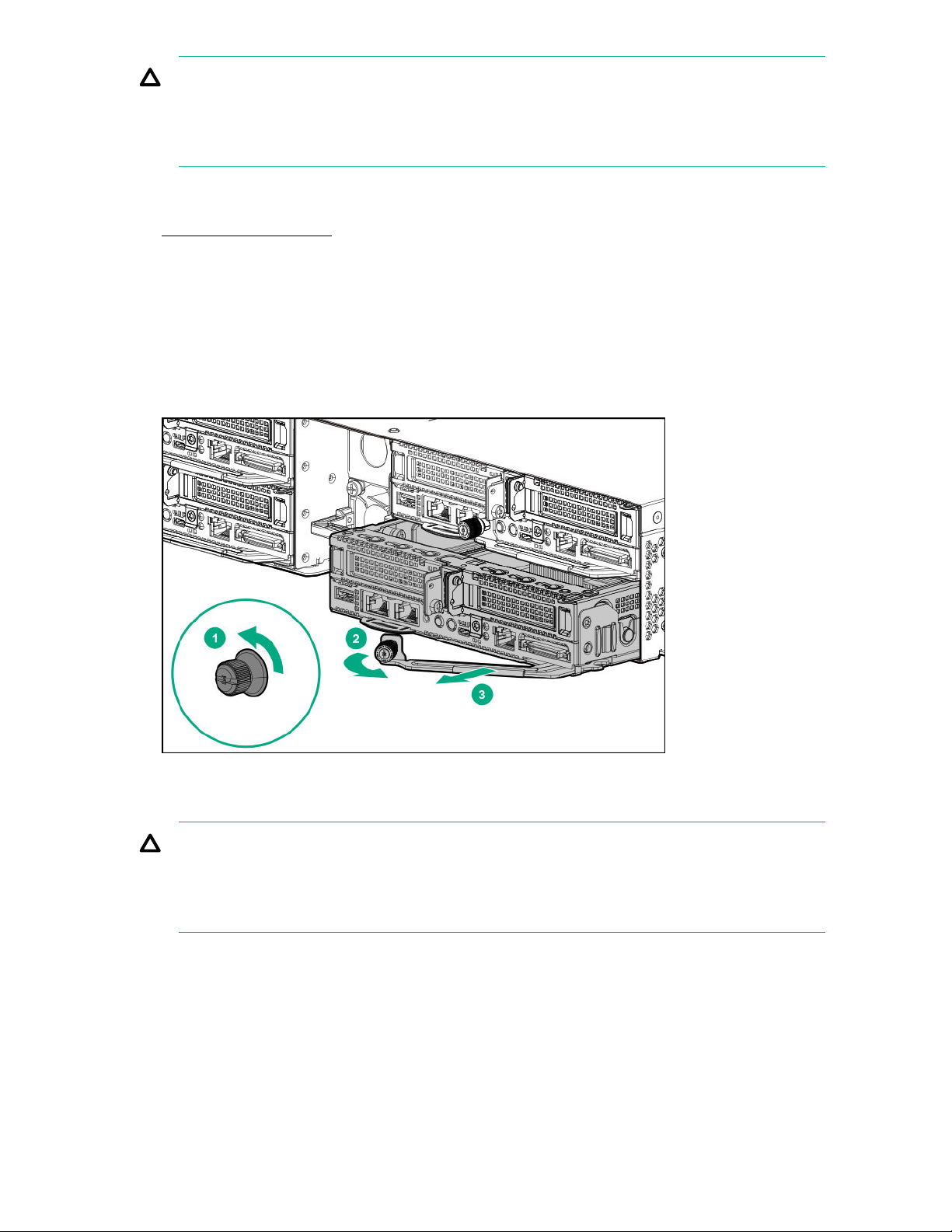
CAUTION: To avoid damage to the server or server blank:
• Always support the bottom of the server or server blank when removing it from the chassis.
• Do not use the release lever to carry the server or server blank.
Procedure
1. Power down the server on page 19.
2. Disconnect all peripheral cables from the server.
3. Remove the server from the chassis:
a. Loosen the release lever thumbscrew.
b. Open the release lever.
c. Use the release lever to pull the server out of the chassis.
Install the server into the chassis
CAUTION: To avoid damage to the server or server blank:
• Always support the bottom of the server or server blank when removing it from the chassis.
• Do not use the release lever to carry the server or server blank.
Procedure
1. Slide the server into the chassis.
2. Close the release lever.
3. Tighten the release lever thumbscrew.
20 Operations
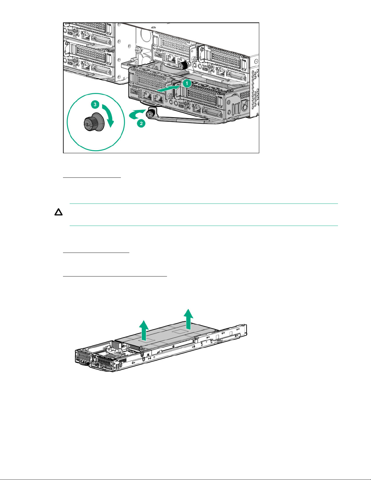
4. Connect all peripheral cables to the server.
5. Power up the server on page 19.
Remove the air baffle
CAUTION: For proper cooling, do not operate the server without the baffles, expansion slot covers,
or blanks installed.
Procedure
1. Power down the server on page 19.
2. Disconnect all peripheral cables from the server.
3. Remove the server from the chassis on page 19.
4. Remove the air baffle.
Operations 21
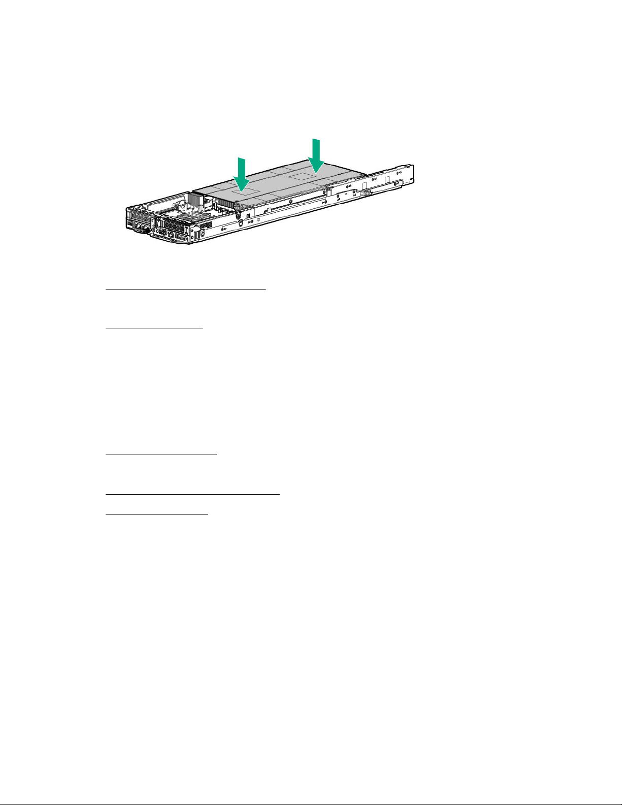
Install the air baffle
Procedure
1. Install the air baffle.
2. Install the server into the chassis on page 20.
3. Connect all peripheral cables to the server.
4. Power up the server on page 19.
Remove the bayonet board
Prerequisites
Before you perform this procedure, make sure that you have a T-10 Torx screwdriver available.
Procedure
1. Power down the server on page 19.
2. Disconnect all peripheral cables from the server.
3. Remove the server from the chassis on page 19.
4. Remove the air baffle on page 21.
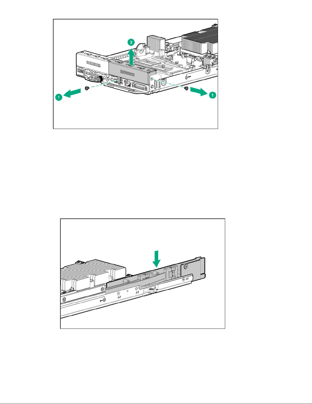
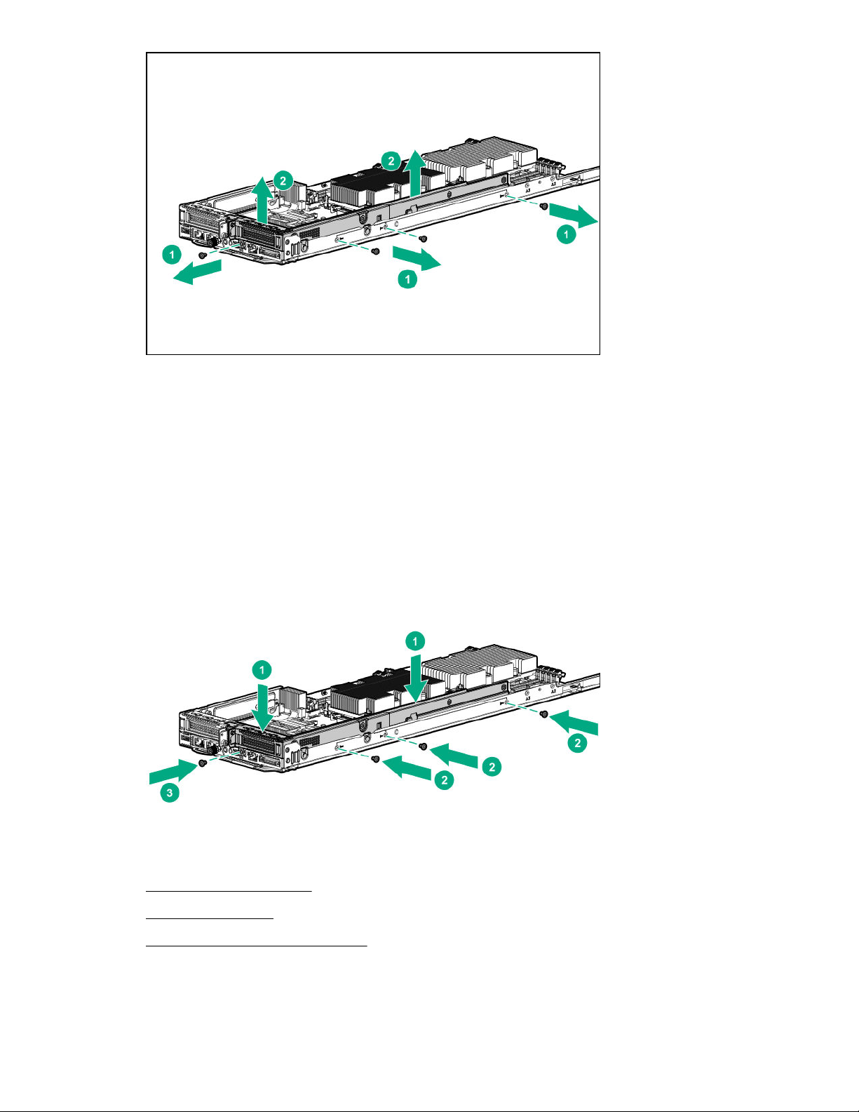
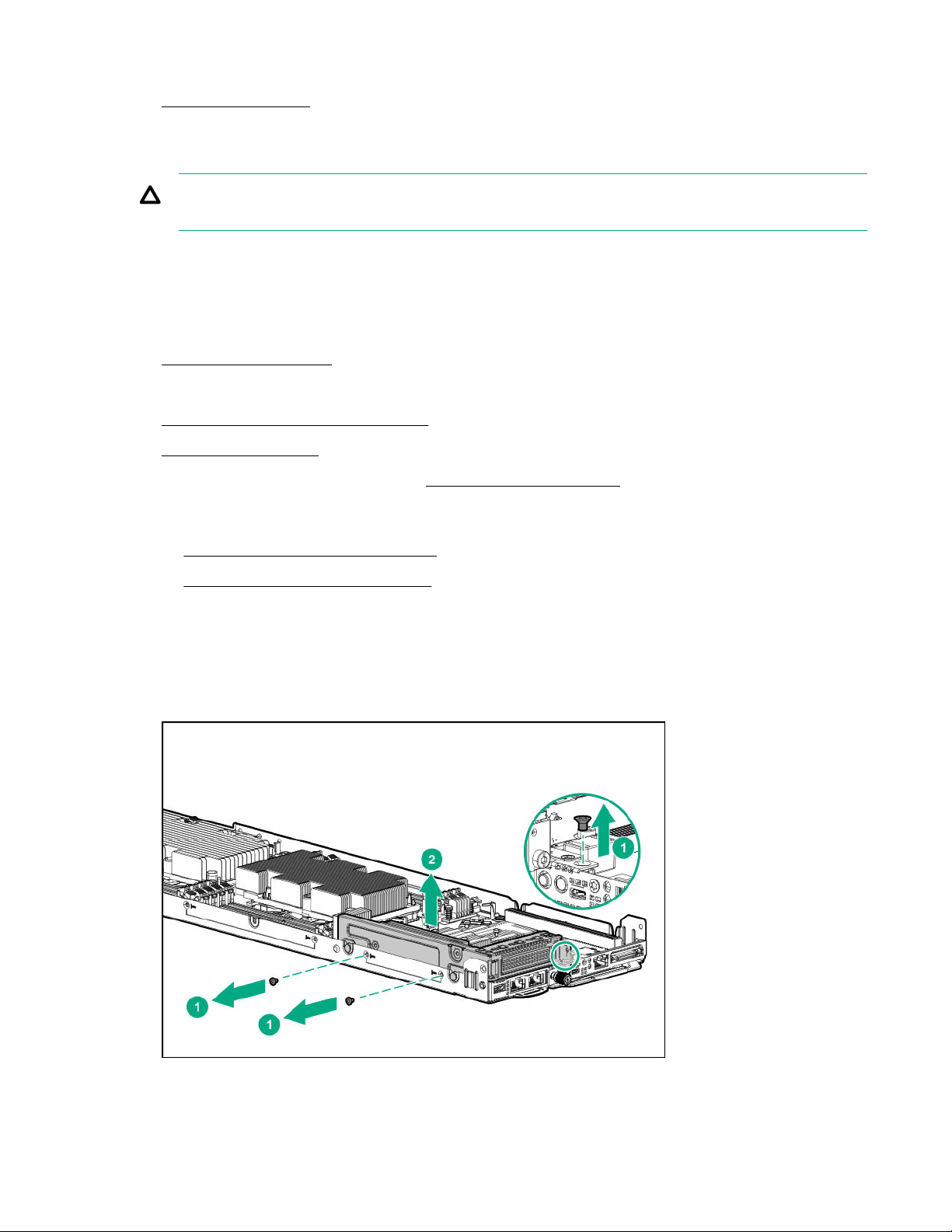
5. Remove the bayonet board:
a. Remove the screws securing the cover to the bayonet board.
22 Operations
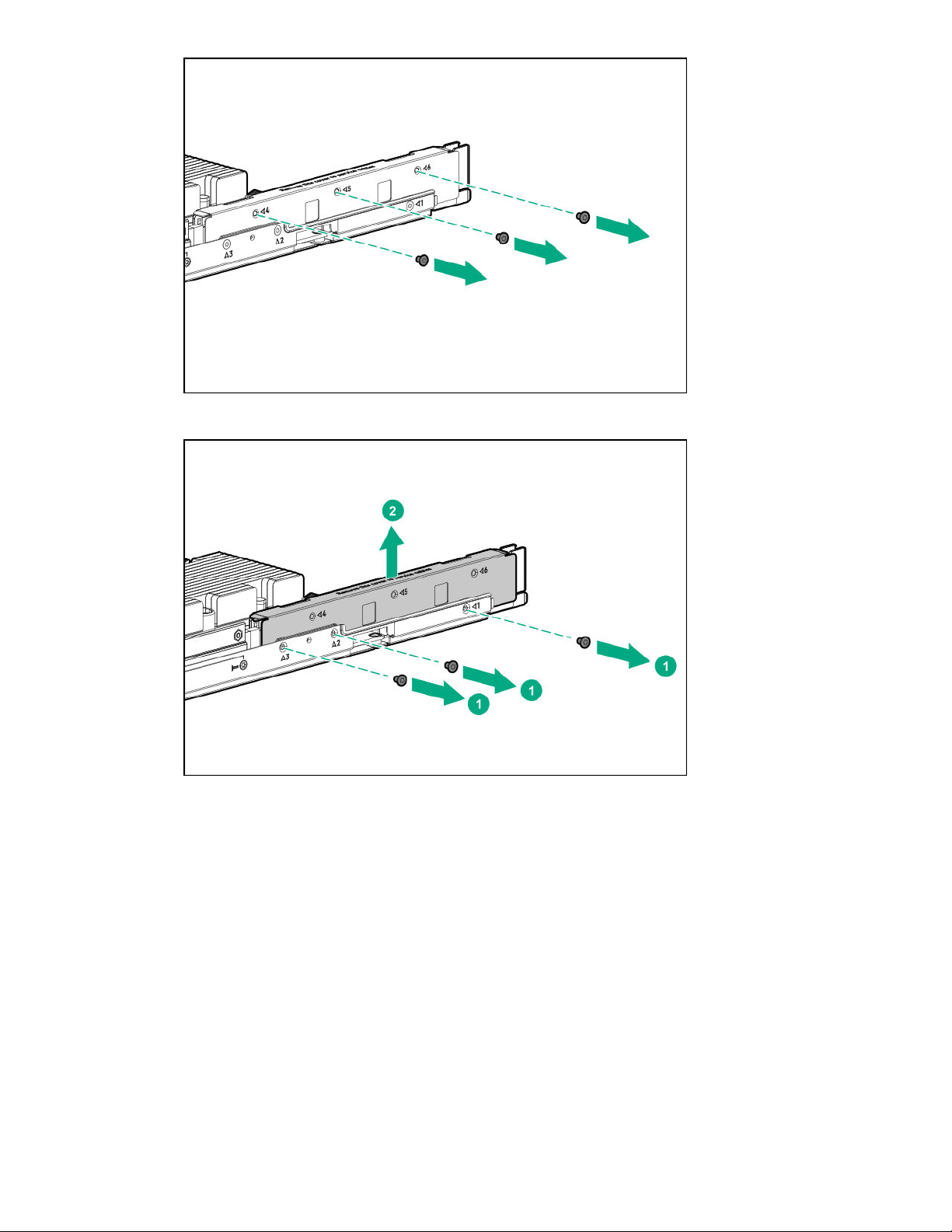
b. Remove the screws securing the cover to the server tray, and then remove the cover.
c. Disconnect the bayonet board cables, and then remove the bayonet board.
Operations 23
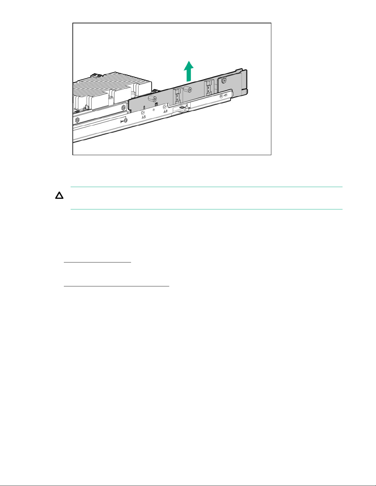
Remove the secondary riser blank
CAUTION: To prevent improper cooling and thermal damage, do not operate the server unless
either riser blank or riser cage is installed.
Prerequisites
Before you perform this procedure, make sure that you have a T-10 Torx screwdriver available.
Procedure
1. Power down the server on page 19.
2. Disconnect all peripheral cables from the server.
3. Remove the server from the chassis on page 19.
4. Remove the secondary riser blank.
24 Operations
Install the bayonet board
Prerequisites
Before you perform this procedure, make sure that you have a T-10 Torx screwdriver available.
Procedure
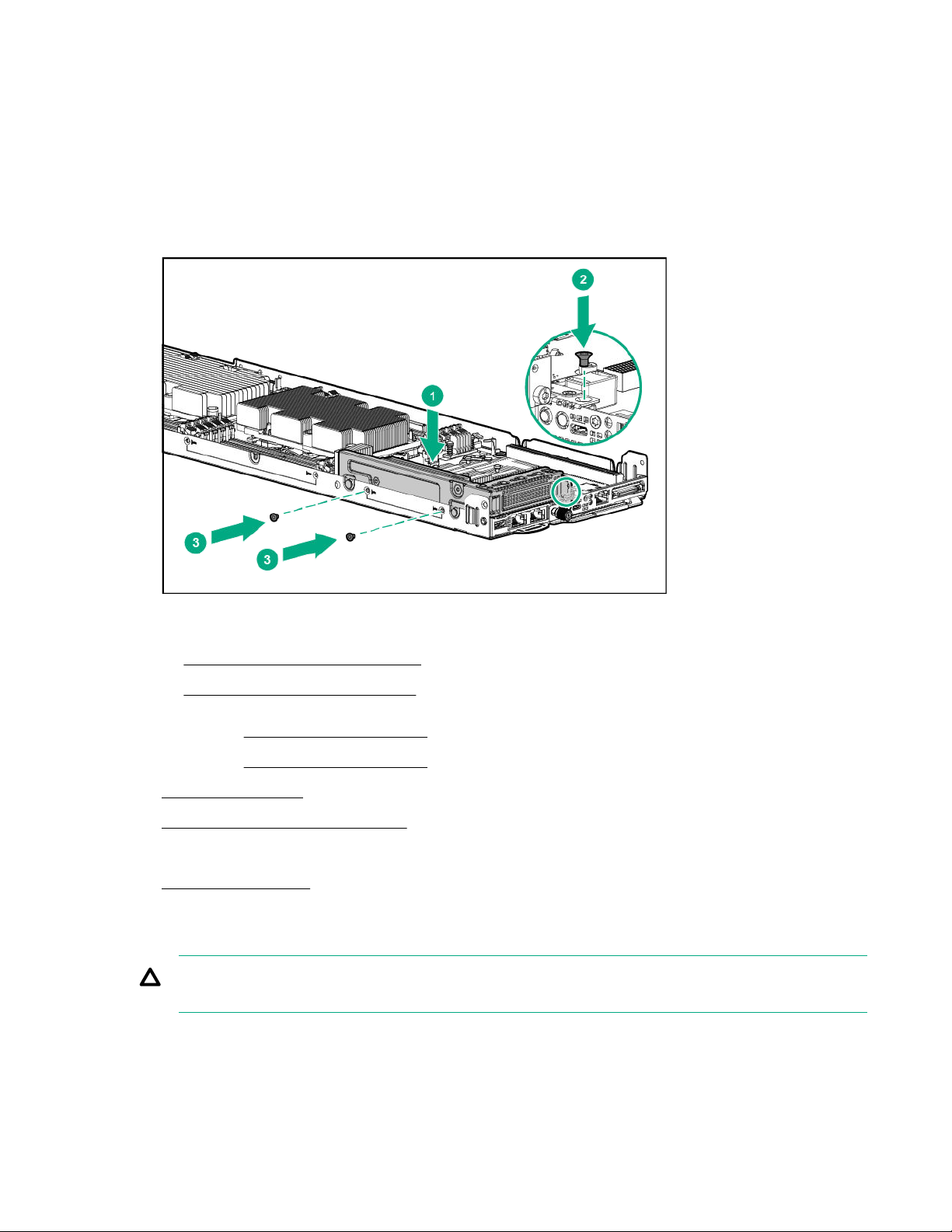
1. Install the bayonet board:
a. Connect all the bayonet board cables.
b. Install the bayonet board. Make sure that the board is firmly seated in the connector.
c. Install the bayonet board cover, and then install the screws to secure it to the server tray.
Operations 25
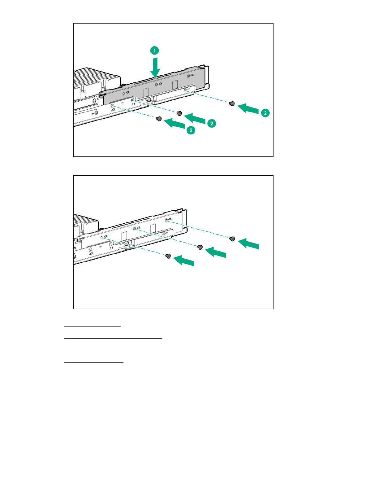
d. Install the screws to secure the cover to the bayonet board.
2. Install the air baffle on page 22.
3. Install the server into the chassis on page 20.
4. Connect all peripheral cables to the server.
5. Power up the server on page 19.
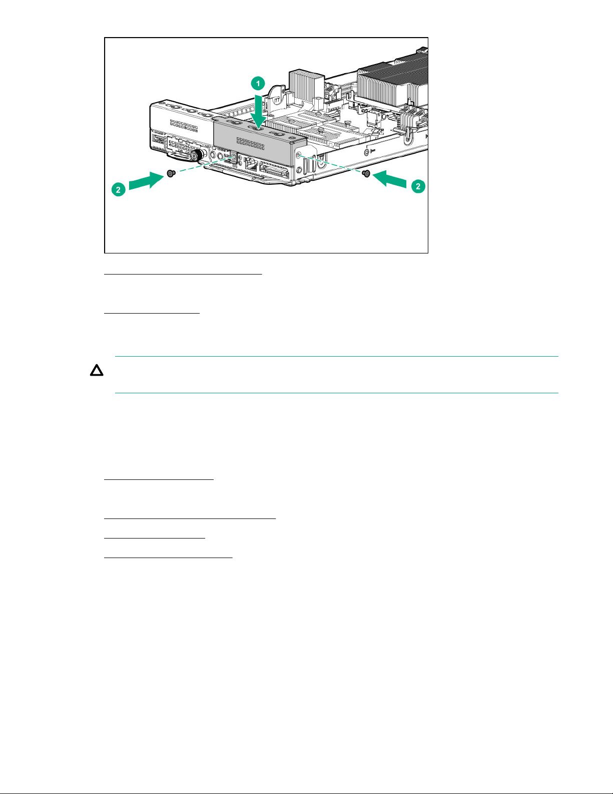
Install the secondary riser blank
Prerequisites
Before you perform this procedure, make sure that you have a T-10 Torx screwdriver available.
Procedure
1. Install the secondary riser blank.
26 Operations
2. Install the server into the chassis on page 20.
3. Connect all peripheral cables to the server.
4. Power up the server on page 19.
Remove the secondary riser cage
CAUTION: To prevent improper cooling and thermal damage, do not operate the server unless
either riser blank or riser cage is installed.
Prerequisites
Before you perform this procedure, make sure that you have a T-10 Torx screwdriver available.
Procedure
1. Power down the server on page 19.
2. Disconnect all peripheral cables from the server.
3. Remove the server from the chassis on page 19.
4. Remove the air baffle on page 21.
5. Remove the bayonet board on page 22.
6. If an expansion board with internal cabling is installed on the riser cage, disconnect these internal
cables from the expansion board.
7. Disconnect all cables from the riser board.
8. Remove the secondary riser cage.
Operations 27
Install the secondary riser cage
Prerequisites
Before you perform this procedure, make sure that you have a T-10 Torx screwdriver available.
Procedure
1. Install the secondary riser cage. Make sure that the riser board is firmly seated in its system board
connectors.
2. Install the bayonet board on page 25.
3. Install the air baffle on page 22.
4. Install the server into the chassis on page 20.
28 Operations
5. Connect all peripheral cables to the server.
6. Power up the server on page 19.
Remove the primary riser cage
CAUTION: To prevent improper cooling and thermal damage, do not operate the server unless
either riser blank or riser cage is installed.
Prerequisites
Before you perform this procedure, make sure that you have a T-10 Torx screwdriver available.
Procedure
1. Power down the server on page 19.
2. Disconnect all peripheral cables from the server.
3. Remove the server from the chassis on page 19.
4. Remove the air baffle on page 21.
5. If a secondary riser option is installed, remove the bayonet board.
6. Do one of the following:
• Remove the secondary riser blank on page 24.
• Remove the secondary riser cage on page 27.
7. If an expansion board with internal cabling is installed on the riser cage, disconnect these internal
cables from the expansion board.
8. Disconnect all cables from the riser board.
9. Remove the primary riser cage.
Operations 29
Install the primary riser cage
Prerequisites
Before you perform this procedure, make sure that you have a T-10 Torx screwdriver available.
Procedure
1. Install the primary riser cage. Make sure that the riser board is firmly seated in its system board the
connector.
2. Do one of the following:
• Install the secondary riser blank on page 26.
• Install the secondary riser cage on page 28.
3. If removed, install the bayonet board.
4. If removed, install the bayonet board.
5. Install the air baffle on page 22.
6. Install the server into the chassis on page 20.
7. Connect all peripheral cables to the server.
8. Power up the server on page 19.
Remove the primary riser blank
CAUTION: To prevent improper cooling and thermal damage, do not operate the server unless
either riser blank or riser cage is installed.
Prerequisites
Before you perform this procedure, make sure that you have a T-10 Torx screwdriver available.
30 Operations
 Loading...