


HP ProLiant DL380 Generation 4 Server
Maintenance and Service Guide
August 2004 (Second Edition)
Part Number 359226-002

© Copyright 2004 Hewlett-Packard Development Company, L.P.
Microsoft, Windows, and Windows NT are U.S. registered trademarks of Microsoft Corporation.
Intel and Xeon are trademarks or registered trademarks of Intel Corporation or its subsidiaries in the United
States and other countries.
Linux is a U.S. registered trademark of Linus Torvalds.
Hewlett-Packard Company shall not be liable for technical or editorial errors or omissions contained
herein. The information in this document is provided “as is” without warranty of any kind and is subject to
change without notice. The warranties for HP products are set forth in the express limited warranty
statements accompanying such products. Nothing herein should be construed as constituting an additional
warranty.
HP ProLiant DL380 Generation 4 Server Maintenance and Service Guide
August 2004 (Second Edition)
Part Number 359226-002
Audience Assumptions
This guide is for an experienced service technician. HP assumes you are qualified in the servicing
of computer equipment and trained in recognizing hazards in products with hazardous energy
levels and are familiar with weight and stability precautions for rack installations.

3
Contents
Illustrated Parts Catalog 7
Mechanical Components...................................................................................................................... 7
System Components.............................................................................................................................8
Removal and Replacement Procedures 13
Required Tools................................................................................................................................... 13
Safety Considerations ........................................................................................................................13
Preventing Electrostatic Discharge.........................................................................................13
Server Warnings and Cautions ...............................................................................................14
Preparation Procedures ......................................................................................................................15
Extending the Server from the Rack....................................................................................... 16
Powering Down the Server..................................................................................................... 17
Removing the Server from the Rack.......................................................................................18
Removing the Access Panel....................................................................................................19
Opening the Cable Management Arm ....................................................................................19
Removing the Cable Management Arm .................................................................................20
Non-Hot-Plug Procedures.................................................................................................................. 21
DVD/CD-ROM Drive ............................................................................................................21
DVD/CD-ROM Drive Ejector Assembly............................................................................... 22
Diskette Drive Option............................................................................................................. 24
Front Bezel .............................................................................................................................24
Front Fan Bracket ...................................................................................................................25
Rear Fan Bracket ....................................................................................................................26
Battery-Backed Write Cache Procedures................................................................................27
PCI Riser Cage Door Latch ....................................................................................................32
PCI Riser Cage .......................................................................................................................33
Expansion Board.....................................................................................................................34
Expansion Slot Cover .............................................................................................................36
Expansion Board Ejector/Divider...........................................................................................37
PCI Slot Release Lever........................................................................................................... 38
PCI Lightpipe and Cover........................................................................................................39
Power Converter Module........................................................................................................40
Power Button/LED Board.......................................................................................................42
DIMMs ...................................................................................................................................42
Processor.................................................................................................................................43
PPM........................................................................................................................................ 46
Battery ....................................................................................................................................47

4 HP ProLiant DL380 Generation 4 Server Maintenance and Service Guide
System Board..........................................................................................................................48
Re-Entering the Server Serial Number and Product ID.......................................................... 50
Hot-Plug Procedures ..........................................................................................................................53
Hot-Plug SCSI Hard Drive..................................................................................................... 53
Hard Drive Blank....................................................................................................................54
Universal Hot-Plug Tape Drive.............................................................................................. 56
Tape Drive Blank....................................................................................................................56
Hot-Plug Power Supply.......................................................................................................... 57
Power Supply Blank ...............................................................................................................59
Hot-Plug Fan...........................................................................................................................60
PCI Hot Plug Expansion Board ..............................................................................................61
PCI Hot Plug Expansion Slot Cover....................................................................................... 63
Server Cabling ...................................................................................................................................67
Cabling ...................................................................................................................................67
Hot-Plug SCSI Hard Drive Cabling........................................................................................67
USB Cabling........................................................................................................................... 75
DVD/CD-ROM Drive Cabling............................................................................................... 76
Diskette Drive Cabling ...........................................................................................................77
Power Button/LED Cabling.................................................................................................... 78
Optional PCI Hot Plug Backplane Cabling ............................................................................78
RILOE II Cabling................................................................................................................... 79
Internal Power Cabling...........................................................................................................79
External Storage Cabling........................................................................................................80
Diagnostic Tools 83
Automatic Server Recovery............................................................................................................... 83
HP Systems Insight Manager.............................................................................................................83
Integrated Management Log ..............................................................................................................84
Integrated Lights-Out Technology.....................................................................................................84
Option ROM Configuration for Arrays..............................................................................................85
HP ProLiant Essentials Rapid Deployment Pack............................................................................... 85
HP ROM-Based Setup Utility............................................................................................................ 86
SmartStart Software........................................................................................................................... 86
ROMPaq Utility...................................................................................................................... 87
System Online ROM Flash Component Utility...................................................................... 87
HP Insight Diagnostics ...........................................................................................................88
Server Component Identification 89
Front Panel Components....................................................................................................................90
Front Panel LEDs and Buttons...........................................................................................................91
Rear Panel Components..................................................................................................................... 92
Rear Panel LEDs and Buttons............................................................................................................ 94
System Board Components................................................................................................................95
System Maintenance Switch................................................................................................... 96

Contents 5
NMI Switch ............................................................................................................................97
Chassis ID Switch................................................................................................................... 97
DIMM Slots............................................................................................................................98
System Board LEDs........................................................................................................................... 99
System LEDs and Internal Health LED Combinations.................................................................... 100
SCSI Backplane Components.......................................................................................................... 102
SCSI Backplane LEDs..................................................................................................................... 103
Hot-Plug SCSI Hard Drive LEDs....................................................................................................104
Hot-Plug SCSI Hard Drive LED Combinations...............................................................................105
Internal PCI Hot Plug LEDs and Button..........................................................................................106
PCI Hot Plug LED Status Combinations .........................................................................................106
PCI Riser Cage LED........................................................................................................................ 107
Remote Management Connector...................................................................................................... 108
Identifying Hot-Plug Fans................................................................................................................109
Hot-Plug Fan LED ...........................................................................................................................110
Power Converter Module LED ........................................................................................................111
Battery-Backed Write Cache LEDs .................................................................................................111
Battery-Backed Write Cache LED Statuses..................................................................................... 112
Specifications 113
Server Specifications........................................................................................................................113
Environmental Specifications .......................................................................................................... 114
Hot-Plug Power Supply Calculations...............................................................................................114
DDR2 SDRAM DIMM Specifications ............................................................................................114
1.44-MB Diskette Drive Specifications ...........................................................................................115
CD-ROM Drive Specifications........................................................................................................ 116
Ultra320 SCSI Hard Drive Specifications .......................................................................................117
Acronyms and Abbreviations 119
Index 123

7
Illustrated Parts Catalog
In This Section
Mechanical Components ................................................................................................................7
System Components .......................................................................................................................8
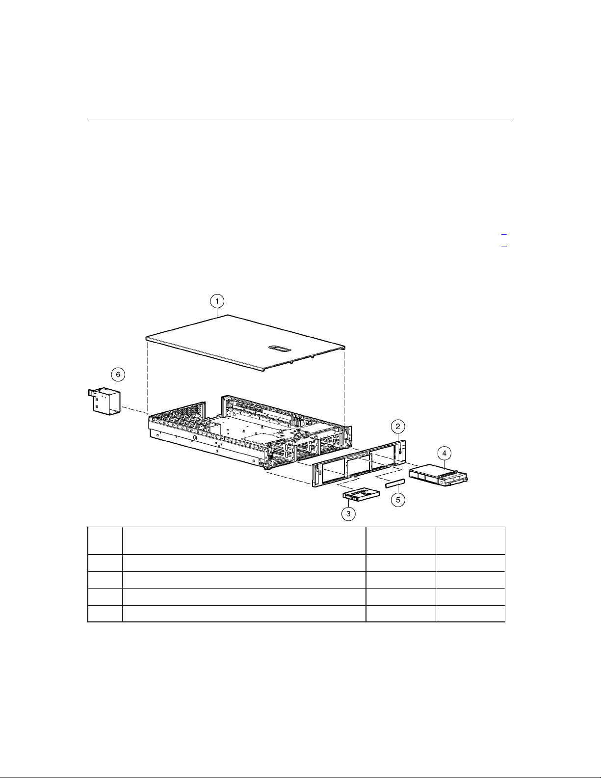
Mechanical Components
Item Description Assembly
Part Number
1 Access panel 344465-001 359244-001
2 Front bezel 344433-001 359245-001
3 Tape drive blank 218512-002 367666-001
4 Hard drive blank 302531-002 122759-001
Spare Part
Number
8 HP ProLiant DL380 Generation 4 Server Maintenance and Service Guide
Item Description Assembly
Part Number
5 Diskette drive slot cover (see "Plastics Kit," Item 28k) — —
6 Power supply blank 344436-001 359246-001
Spare Part
Number
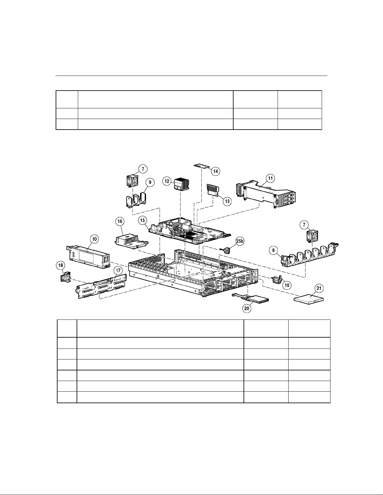
System Components
Item Description Assembly
Part Number
7 Hot-plug fan, 60 mm 279036-001 289544-001
8 Front fan bracket, 6 bay 279037-002 371148-001
9 Rear fan bracket, 2 bay 279060-001 289558-001
10 Hot-plug power supply, 575 W 321632-001 338022-001
11 PCI riser cages
System Components
Spare Part
Number

Illustrated Parts Catalog 9
Item Description Assembly
Part Number
12 Processor assemblies
13 Processor Power Module, 12 V, 105 A 326294-001 347884-001
14 Smart Array 6i cache module 012304-001 351518-001
15 System board, with processor cages and system battery 012317-001 359251-001
16 Power converter module 321633-001 361667-001
17 SCSI backplane, 6 bay 012055-001 359253-001
18 SCSI terminator 011730-001 289563-001
19 Power button/LED board 010963-002 366300-001
a) PCI riser cage, with non-hot-plug PCI-X (standard) 344437-001 359248-001
b) PCI riser cage, with non-hot-plug PCI Express (optional) * 344437-003 359259-001
c) PCI riser cage, with Hot Plug PCI-X (optional) * 344437-002 359260-001
a) Intel® 3.2-GHz Xeon™ 1-MB L2 cache 349931-003 374233-001
b) Intel® 3.4-GHz Xeon™ 1-MB L2 cache 349931-002 364757-001
c) Intel® 3.6-GHz Xeon™ 1-MB L2 cache 349931-001 364758-001
Boards
Spare Part
Number
20 Diskette drive, slimline, 1.44 MB (optional) 279983-001 289550-001
21 CD-ROM drive, removable slimline, IDE, 24X 222837-001 228508-001
22 DVD-ROM drive, removable slimline, 8X * 264007-B21 268795-001
23 SCSI cable kit *
24 Signal cable kit * — 366063-001
Media Devices
Cables
a) SCSI cable, short, 68 pin 199606-019 —
b) SCSI cable, long, 68 pin 166298-038 —
c) System cable, SCSI, 50 pin 279161-001 —
a) Power button/LED board cable, 14 pin 219048-001 —
289567-001

10 HP ProLiant DL380 Generation 4 Server Maintenance and Service Guide
Item Description Assembly
Part Number
25 Miscellaneous cable kit — 289569-001
26 2U Quick Deploy Rail System * — 359254-001
27 Hardware kit * — 228527-001
28 Plastics kit * — 359720-001
b) PCI Hot Plug LED board cable 219049-002 —
c) Universal Media Bay cable, 50 pin 356452-001 —
a) Diskette drive cable * 235183-001 —
b) USB cable and connector 346187-001 —
Rack Mounting Hardware
Miscellaneous
a) Screws, T-15, flat-head 228213-001 —
b) Expansion slot cover 228072-001 —
c) Screws, 6-32 192308-009 —
a) PCI slot release lever 228194-002 —
b) PCI lightpipe, rear 279061-001 —
Spare Part
Number
29 AC power cord * 163719-002 187335-001
30 DVD/CD-ROM drive ejector assembly * 356443-001 371114-001
c) PCI lightpipe, cover 218518-001 —
d) PCI riser cage door latch 279062-001 —
e) Thumbscrew with molded cap, PCI slot 1 179333-003 —
f) Standoff 225249-002 —
g) Plastic standoff 0.134 225250-007 —
h) Battery clip 280247-002 —
i) PCI card guide retainer 233614-004 —
j) Thumbscrew knob 249083-001 —
k) Diskette drive slot cover 352834-001 —

Illustrated Parts Catalog 11
Item Description Assembly
Part Number
31 PCI expansion board ejector * 279035-002 359261-001
32 Battery, 3.3 V, lithium * 334149-001 179322-001
33 Country kit * 359722-001
34 Return kit, pack box, and cushions * — 289545-001
35 Torx tool * 120473-001 199630-001
36 DIMM, 512 MB, registered DDR2 SDRAM * 343055-B21 359241-001
37 DIMM, 1 GB, registered DDR2 SDRAM * 343056-B21 359242-001
38 DIMM, 2 GB, registered DDR2 SDRAM * 343057-B21 359243-001
39 Battery-Backed Write Cache battery pack * 274779-001 307132-001
40 Battery-Backed Write Cache battery bracket * 335771-001 349989-001
41 SCSI Ultra320 universal hot-plug hard drive *
Memory
Options
a) 36.4-GB 10K rpm 286713-B22 289041-001
b) 72.8-GB 10K rpm 268714-B22 289042-001
Spare Part
Number
c) 146.8-GB 10K rpm 286716-B22 289044-001
d) 18.2-GB 15K rpm 286775-B22 289240-001
e) 36.4-GB 15K rpm 286776-B22 289241-001
f) 72.8-GB 15K rpm 289788-B22 289243-001
*Not shown


13
Removal and Replacement Procedures
In This Section
Required Tools .............................................................................................................................13
Safety Considerations...................................................................................................................13
Preparation Procedures.................................................................................................................15
Non-Hot-Plug Procedures.............................................................................................................21
Hot-Plug Procedures.....................................................................................................................53
Server Cabling..............................................................................................................................67
Required Tools
You need the following items for some procedures:
•
Torx T-15 tool (provided inside the server)
•
HP Insight Diagnostics software ("HP Insight Diagnostics" on page 88
Safety Considerations
Before performing service procedures, review all the safety information.
Preventing Electrostatic Discharge
To prevent damaging the system, be aware of the precautions you need to follow
when setting up the system or handling parts. A discharge of static electricity
from a finger or other conductor may damage system boards or other staticsensitive devices. This type of damage may reduce the life expectancy of the
device.
To prevent electrostatic damage:
• Avoid hand contact by transporting and storing products in static-safe
containers.
)
14 HP ProLiant DL380 Generation 4 Server Maintenance and Service Guide
•
Keep electrostatic-sensitive parts in their containers until they arrive at staticfree workstations.
•
Place parts on a grounded surface before removing them from their
containers.
•
Avoid touching pins, leads, or circuitry.
•
Always be properly grounded when touching a static-sensitive component or
assembly.
Server Warnings and Cautions
Before installing a server, be sure that you understand the following warnings
and cautions.
WARNING: To reduce the risk of electric shock or damage
to the equipment:
Do not disable the power cord grounding plug. The grounding
•
plug is an important safety feature.
•
Plug the power cord into a grounded (earthed) electrical outlet
that is easily accessible at all times.
•
Unplug the power cord from the power supply to disconnect
power to the equipment.
•
Do not route the power cord where it can be walked on or
pinched by items placed against it. Pay particular attention to
the plug, electrical outlet, and the point where the cord extends
from the server.
WARNING: To reduce the risk of personal injury from hot
surfaces, allow the drives and the internal system components to
cool before touching them.

Removal and Replacement Procedures 15
CAUTION: Do not operate the server for long periods without
the access panel. Operating the server without the access panel results
in improper airflow and improper cooling that can lead to thermal
damage.
Preparation Procedures
To access some components and perform certain service procedures, you must
perform one or more of the following procedures:
• Extend the server from the rack ("Extending the Server from the Rack" on
page 16
If you are performing service procedures in an HP, Compaq branded, telco,
or third-party rack cabinet, you can use the locking feature of the rack rails to
support the server and gain access to internal components.
For more information about telco rack solutions, refer to the
RackSolutions.com website (http://www.racksolutions.com/hp
).
).
• Power down the server ("Powering Down the Server" on page 17
).
If you must remove a server from a rack or a non-hot-plug component from a
server, power down the server.
• Remove the server from the rack ("Removing the Server from the Rack" on
page 18
).
If the rack environment, cabling configuration, or the server location in the
rack creates awkward conditions, remove the server from the rack.
16 HP ProLiant DL380 Generation 4 Server Maintenance and Service Guide
Extending the Server from the Rack
1. Pull down the quick release levers on each side of the server to release the
server from the rack.
2. Extend the server on the rack rails until the server rail-release latches engage.
WARNING: To reduce the risk of personal injury or
equipment damage, be sure that the rack is adequately stabilized
before extending a component from the rack.
WARNING: To reduce the risk of personal injury, be
careful when pressing the server rail-release latches and sliding
the server into the rack. The sliding rails could pinch your fingers.
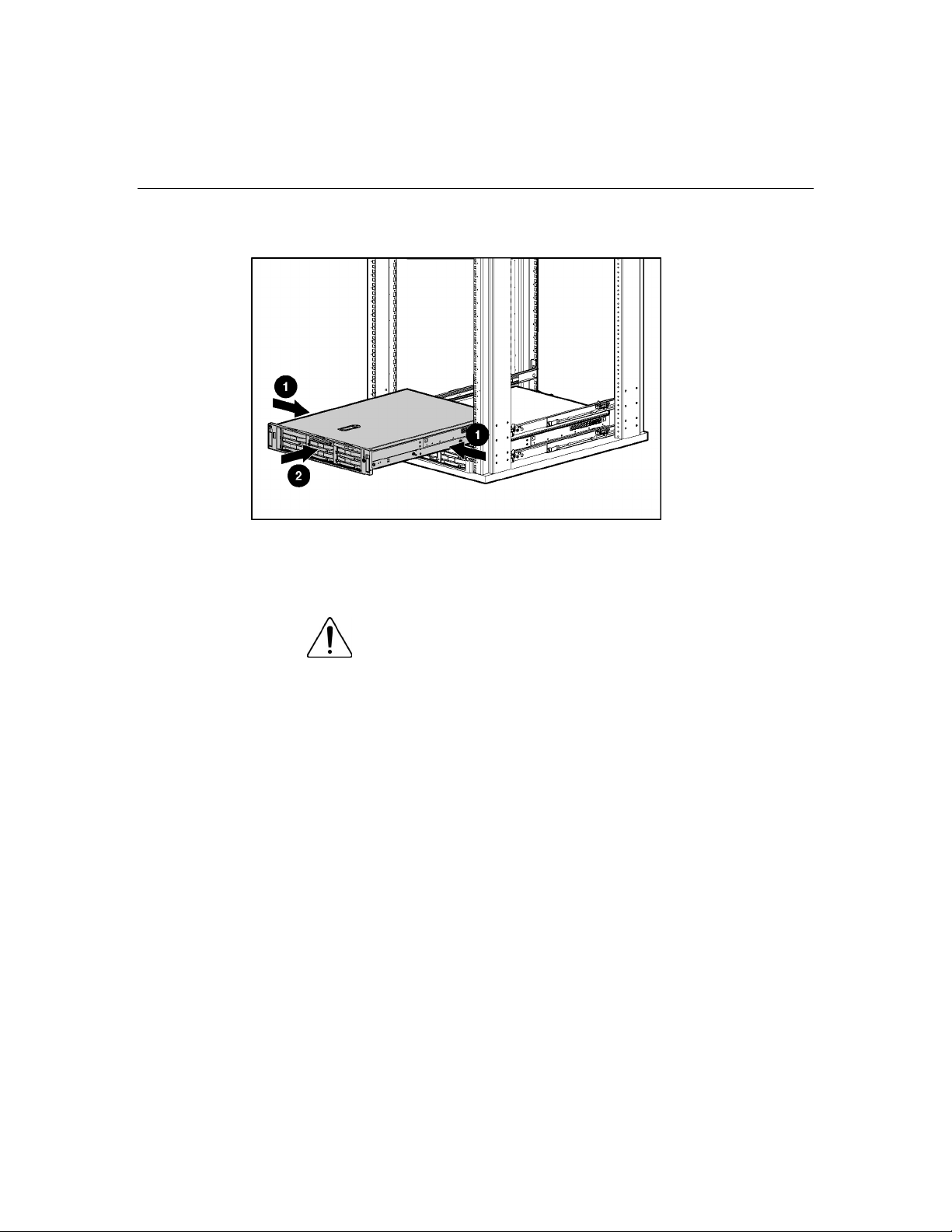
3. After performing the installation or maintenance procedure, slide the server
back into the rack:
Removal and Replacement Procedures 17
a. Press the server rail-release latches and slide the server fully into rack.
b. Press the server firmly into the rack to secure it in place.
Powering Down the Server
WARNING: To reduce the risk of personal injury, electric
shock, or damage to the equipment, remove the power cord to
remove power from the server. The front panel Power On/Standby
button does not completely shut off system power. Portions of the
power supply and some internal circuitry remain active until AC
power is removed.
IMPORTANT: If installing a hot-plug device, it is not necessary to
power down the server.
1. Back up the server data.
2. Shut down the operating system as directed by the operating system
documentation.
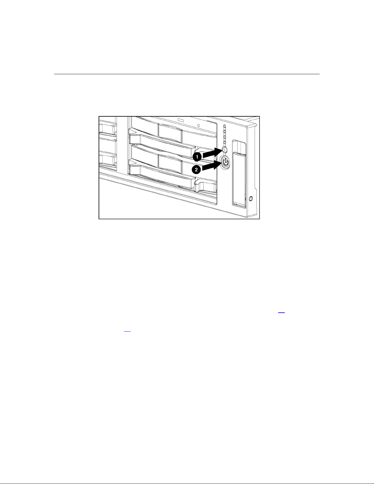
3. If the server is installed in a rack, press the UID LED button on the front
panel (1). Blue LEDs illuminate on the front and rear panels of the server.
18 HP ProLiant DL380 Generation 4 Server Maintenance and Service Guide
4. Press the Power On/Standby button to place the server in standby mode (2).
When the server activates standby power mode, the system power LED
changes to amber.
5. If the server is installed in a rack, locate the server by identifying the
illuminated rear UID LED button.
6. Disconnect the power cords.
The system is now without power.
Removing the Server from the Rack
To remove the server from an HP, Compaq branded, telco, or third-party rack:
1. Power down the server ("Powering Down the Server" on page 17
2. Extend the server from the rack ("Extending the Server from the Rack" on
page 16
3. Disconnect the cabling and remove the server from the rack. For more
information, refer to the documentation that ships with the rack mounting
option.
4. Place the server on a sturdy, level surface.
).
).
Removal and Replacement Procedures 19
Removing the Access Panel
WARNING: To reduce the risk of personal injury from hot
surfaces, allow the drives and the internal system components to
cool before touching them.
CAUTION: Do not operate the server for long periods without
the access panel. Operating the server without the access panel results
in improper airflow and improper cooling that can lead to thermal
damage.
1. Power down the server if performing a non-hot-plug installation or
maintenance procedure ("Powering Down the Server" on page 17
).
2. Extend the server from the rack, if applicable ("Extending the Server from
the Rack" on page 16
3. Lift up on the hood latch handle and remove the access panel.
).
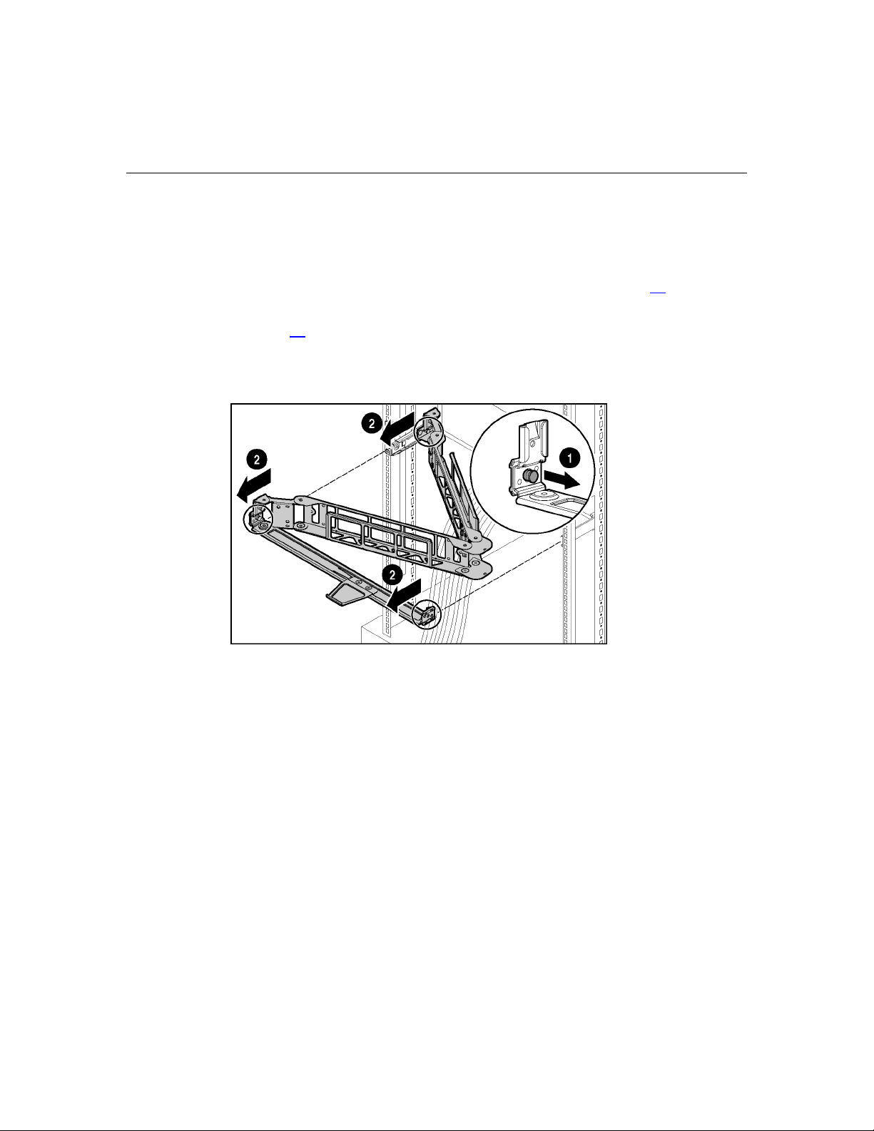
Opening the Cable Management Arm
To access the server rear panel, open the cable management arm:
20 HP ProLiant DL380 Generation 4 Server Maintenance and Service Guide
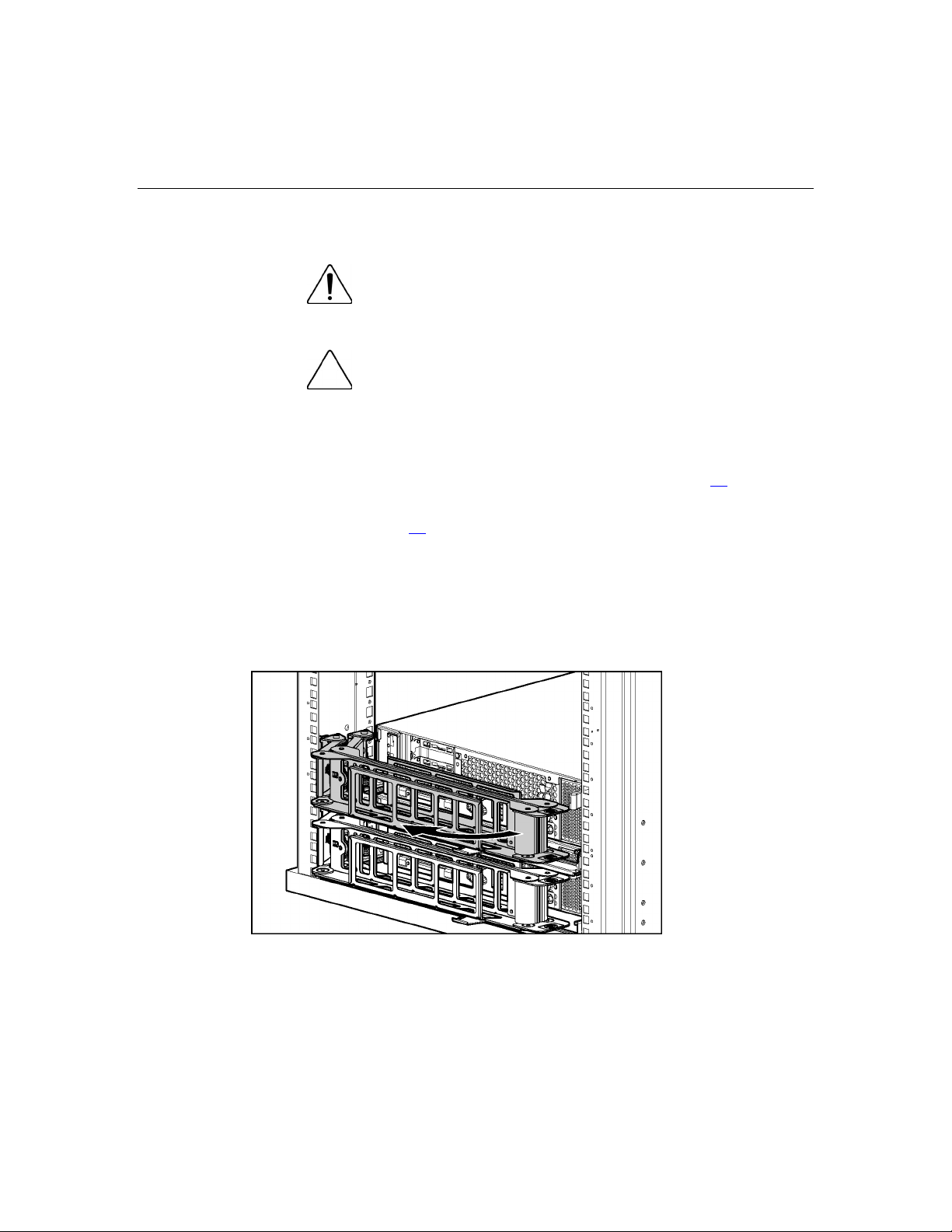
Removing the Cable Management Arm
To remove the component:
1. Power down the server ("Powering Down the Server" on page 17
).
2. Open the cable management arm ("Opening the Cable Management Arm" on
page 19
).
3. Remove the cables from the cable trough.
4. Remove the cable management arm.
To replace the component, reverse the removal procedure.

21
Non-Hot-Plug Procedures
In This Section
DVD/CD-ROM Drive ..................................................................................................................21
DVD/CD-ROM Drive Ejector Assembly.....................................................................................22
Diskette Drive Option...................................................................................................................24
Front Bezel ...................................................................................................................................24
Front Fan Bracket.........................................................................................................................25
Rear Fan Bracket ..........................................................................................................................26
Battery-Backed Write Cache Procedures .....................................................................................27
PCI Riser Cage Door Latch..........................................................................................................32
PCI Riser Cage .............................................................................................................................33
Expansion Board ..........................................................................................................................34
Expansion Slot Cover...................................................................................................................36
Expansion Board Ejector/Divider.................................................................................................37
PCI Slot Release Lever.................................................................................................................38
PCI Lightpipe and Cover..............................................................................................................39
Power Converter Module..............................................................................................................40
Power Button/LED Board ............................................................................................................42
DIMMs .........................................................................................................................................42
Processor.......................................................................................................................................43
PPM ..............................................................................................................................................46
Battery ..........................................................................................................................................47
System Board................................................................................................................................48
Re-Entering the Server Serial Number and Product ID................................................................50
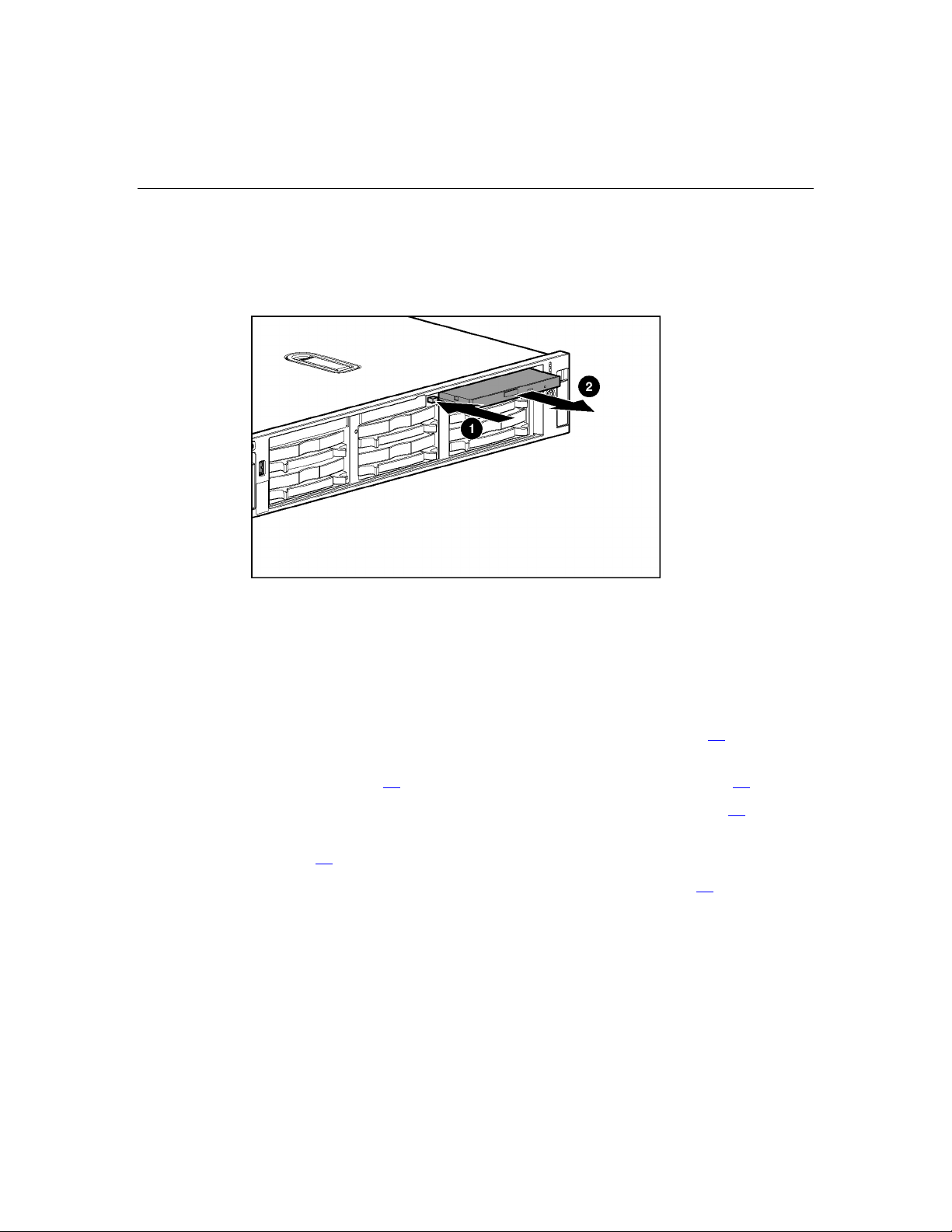
DVD/CD-ROM Drive
To remove the component:
do not operate the server unless all bays are populated with either a
component or a blank.
1. Power down the server ("Powering Down the Server" on page 17).
CAUTION: To prevent improper cooling and thermal damage,
22 HP ProLiant DL380 Generation 4 Server Maintenance and Service Guide
IMPORTANT: The ejector button is recessed to prevent accidental
ejection; it may be helpful to use a pen or similar shaped object to
access the button.
2. Remove the drive.
To replace the drive, slide the drive into the bay until the drive is fully seated.
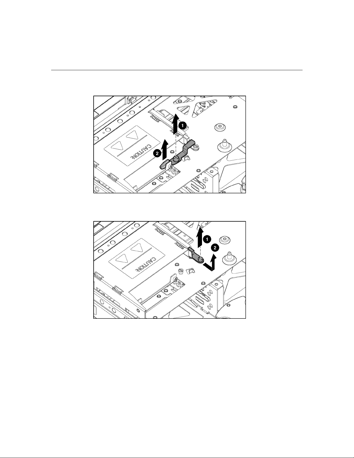
DVD/CD-ROM Drive Ejector Assembly
To remove the component:
1. Power down the server ("Powering Down the Server" on page 17).
2. Extend or remove the server from the rack ("Extending the Server from the
Rack" on page 16
3. Remove the access panel ("Removing the Access Panel" on page 19
4. Remove the DVD/CD-ROM drive, if installed ("DVD/CD-ROM Drive" on
page 21
).
5. Remove the diskette drive ("Diskette Drive Option" on page 24
, "Removing the Server from the Rack" on page 18).
).
).
Removal and Replacement Procedures 23
6. Remove the ejector lever.
7. Press and hold the ejector button.
8. Remove the ejector assembly.
To replace the component, reverse the removal procedure.
24 HP ProLiant DL380 Generation 4 Server Maintenance and Service Guide
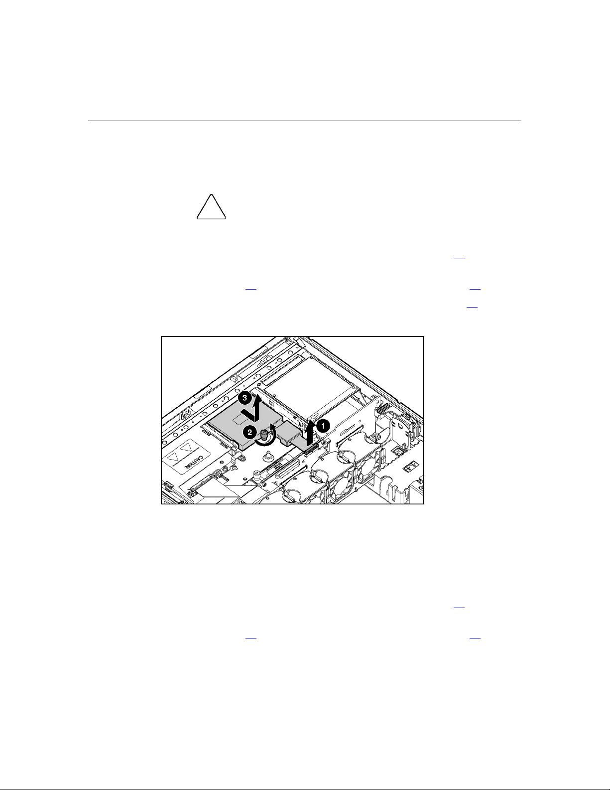
Diskette Drive Option
To remove the component:
CAUTION: To prevent improper cooling and thermal damage,
do not operate the server unless all bays are populated with either a
component or a blank.
1. Power down the server ("Powering Down the Server" on page 17).
2. Extend or remove the server from the rack ("Extending the Server from the
Rack" on page 16
, "Removing the Server from the Rack" on page 18).
3. Remove the access panel ("Removing the Access Panel" on page 19
4. Remove the diskette drive.
To replace the component, reverse the removal procedure.
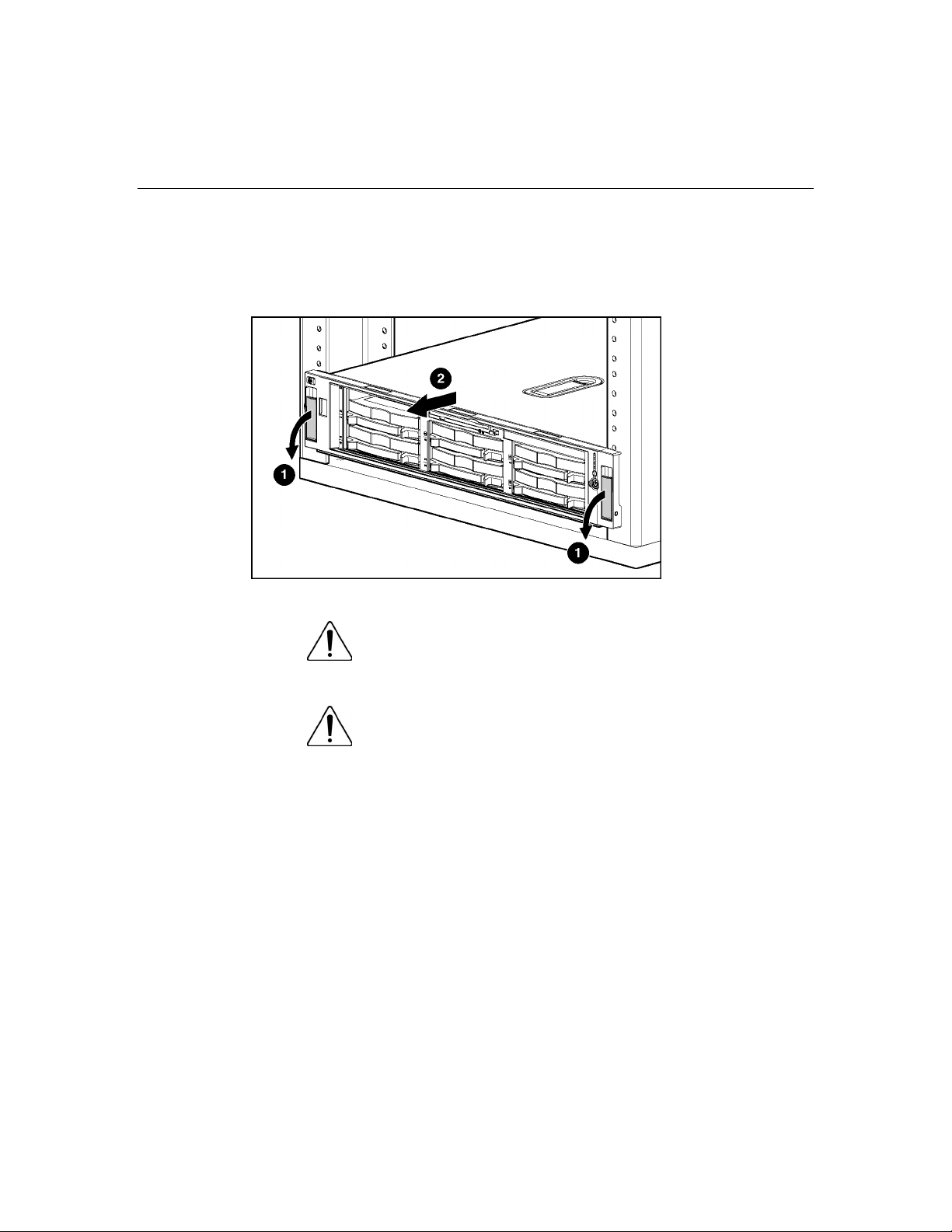
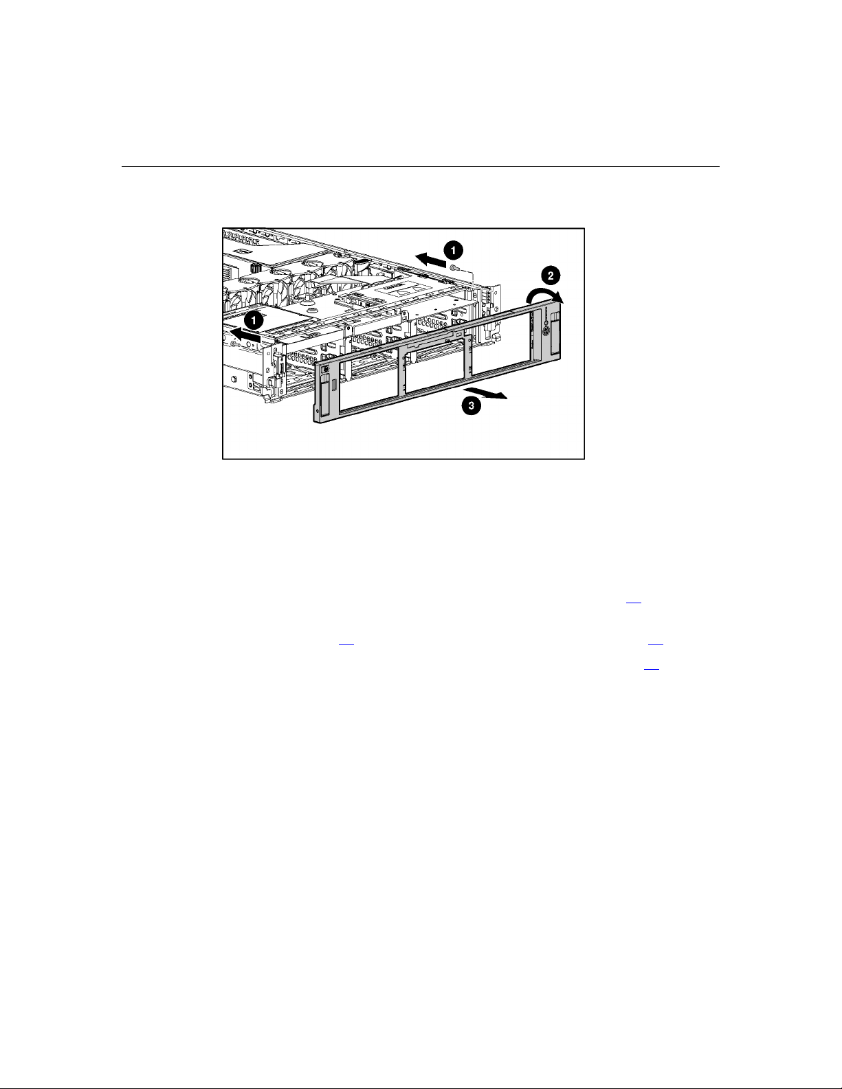
Front Bezel
To remove the component:
).
1. Power down the server ("Powering Down the Server" on page 17).
2. Extend or remove the server from the rack ("Extending the Server from the
Rack" on page 16
, "Removing the Server from the Rack" on page 18).
Removal and Replacement Procedures 25
3. Remove the two screws and detach the front bezel.
To replace the component, reverse the removal procedure.
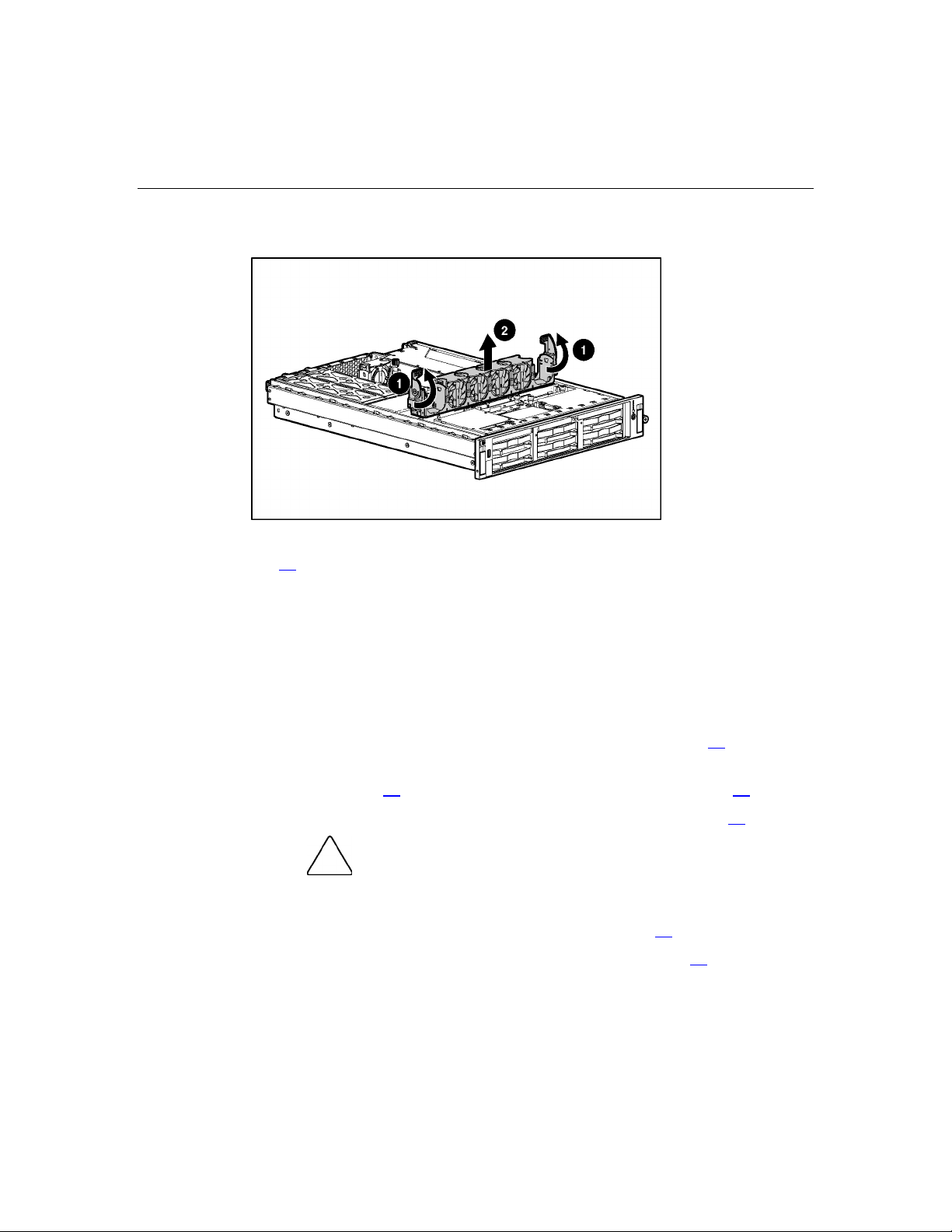
Front Fan Bracket
To remove the component:
1. Power down the server ("Powering Down the Server" on page 17
).
2. Extend or remove the server from the rack ("Extending the Server from the
Rack" on page 16
3. Remove the access panel ("Removing the Access Panel" on page 19
, "Removing the Server from the Rack" on page 18).
).
26 HP ProLiant DL380 Generation 4 Server Maintenance and Service Guide
4. Remove the front fan bracket.
5. Remove all hot-plug fans from the front fan bracket ("Hot-Plug Fan" on page
60
).
To replace the front fan bracket, reverse the removal steps and press down on the
top of each fan to be sure it is seated properly.
Rear Fan Bracket
To remove the component:
1. Power down the server ("Powering Down the Server" on page 17
2. Extend or remove the server from the rack ("Extending the Server from the
Rack" on page 16
3. Remove the access panel ("Removing the Access Panel" on page 19
boards, power down the server and remove all AC power cords before
removing or installing the PCI riser cage.
4. Remove the PCI riser cage ("PCI Riser Cage" on page 33).
5. Remove the front fan bracket ("Front Fan Bracket" on page 25
).
, "Removing the Server from the Rack" on page 18).
).
CAUTION: To prevent damage to the server or expansion
).
Removal and Replacement Procedures 27
IMPORTANT: For this procedure, you do not need to remove the hot-
plug fans from the front fan bracket. When reinstalling the front fan
bracket, press the top of each fan to be sure it seats securely.
6. Remove the hot-plug fans from the rear fan bracket ("Hot-Plug Fan" on page
60
).
7. Remove the system board.
NOTE: When removing the system board, you may leave the DIMMs,
the processors, the PPMs, the Smart Array 6i memory module, and the
system battery on the system board, unless you are replacing them as
failed items.
8. Remove the rear fan bracket.
To replace the component, reverse the removal procedure.
Battery-Backed Write Cache Procedures
Two types of procedures are provided for the BBWC option.
1. Removal and replacement of failed components:
− Removing the Smart Array 6i Cache Module ("Smart Array 6i Cache
Module" on page 28
− Removing the BBWC Battery Pack ("Battery-Backed Write Cache
Battery Pack" on page 30
)
)

28 HP ProLiant DL380 Generation 4 Server Maintenance and Service Guide
2. Recovery of cached data from a failed server ("Recovering Data from the
Battery-Backed Write Cache" on page 31
CAUTION: Do not detach the cable that connects the battery
pack to the cache module. Detaching the cable causes any unsaved
data in the cache module to be lost.
)
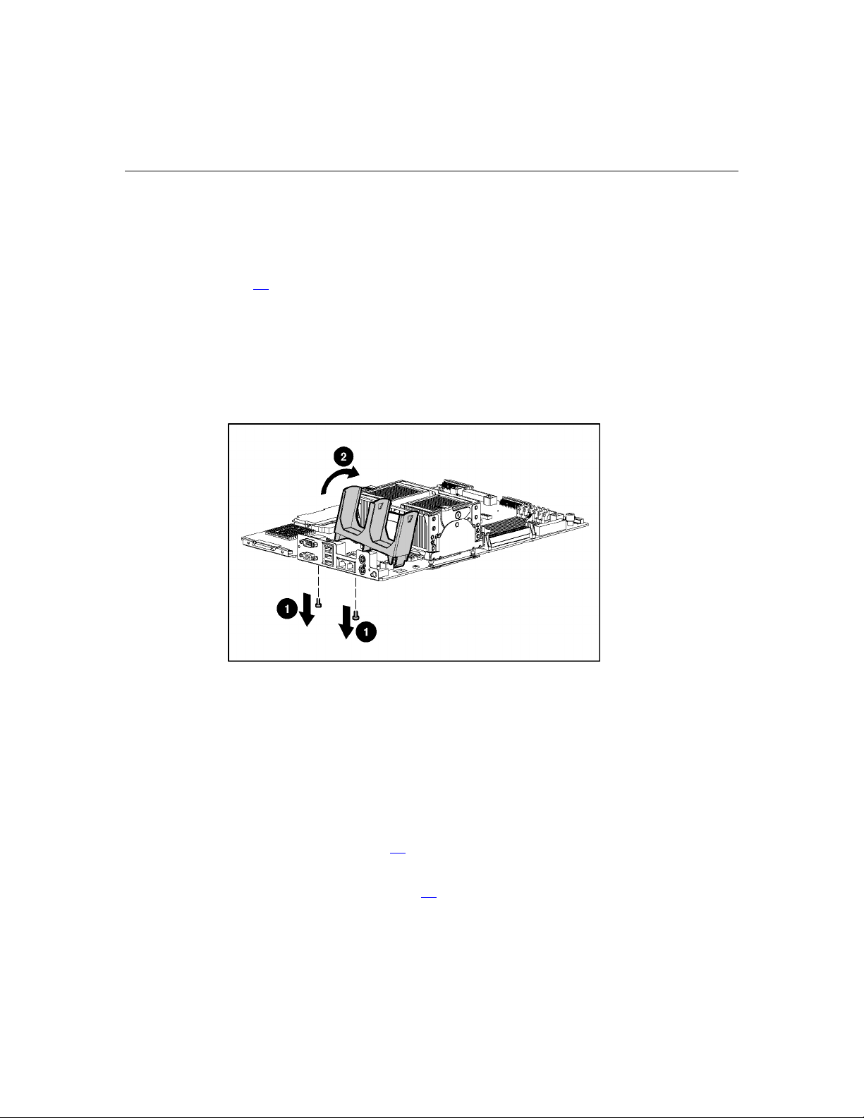
Smart Array 6i Cache Module
To remove the component:
1. Power down the server ("Powering Down the Server" on page 17
).
2. Extend or remove the server from the rack ("Extending the Server from the
Rack" on page 16
3. Remove the access panel ("Removing the Access Panel" on page 19
CAUTION: To prevent damage to the server or expansion
boards, power down the server and remove all AC power cords before
removing or installing the PCI riser cage.
, "Removing the Server from the Rack" on page 18).
).
4. Remove the PCI riser cage ("PCI Riser Cage" on page 33).
CAUTION: To prevent a server malfunction or damage to the
equipment, do not add or remove the battery pack while an array
capacity expansion, RAID level migration, or stripe size migration is in
progress.
CAUTION: After the server is powered down, wait 15 seconds
and then check the amber LED before unplugging the cable from the
cache module. If the amber LED blinks after 15 seconds, do not remove
the cable from the cache module. The cache module is backing up data,
and data will be lost if the cable is detached.
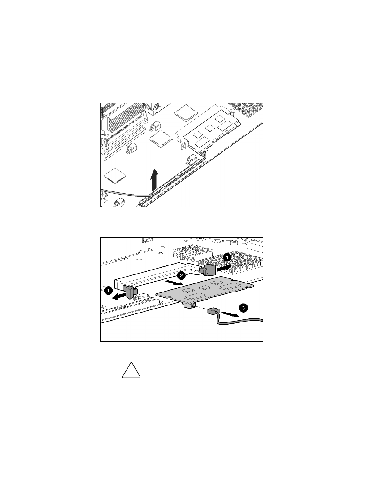
Removal and Replacement Procedures 29
5. Remove the cable from the plastic retainer.
6. Remove the Smart Array 6i cache module.
7. Disconnect the cable.
To replace the component, reverse the removal procedure.
CAUTION: To prevent damage to the cache module during
installation, be sure the cache module is fully inserted before pressing
down.
30 HP ProLiant DL380 Generation 4 Server Maintenance and Service Guide
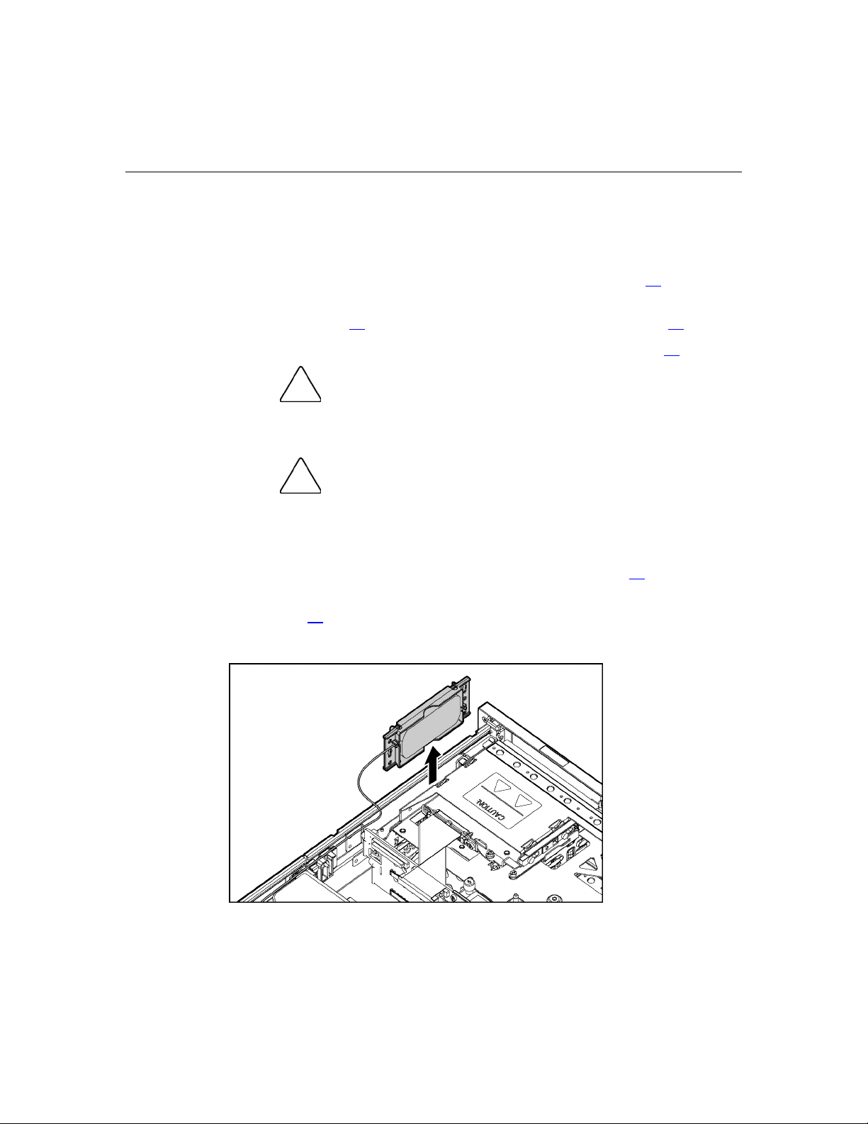
Battery-Backed Write Cache Battery Pack
To remove the component:
1. Power down the server ("Powering Down the Server" on page 17
).
2. Extend or remove the server from the rack ("Extending the Server from the
Rack" on page 16
3. Remove the access panel ("Removing the Access Panel" on page 19
CAUTION: To prevent a server malfunction or damage to the
equipment, do not add or remove the battery pack while an array
capacity expansion, RAID level migration, or stripe size migration is in
progress.
CAUTION: After the server is powered down, wait 15 seconds
and then check the amber LED before unplugging the cable from the
cache module. If the amber LED blinks after 15 seconds, do not remove
the cable from the cache module. The cache module is backing up data,
and data will be lost if the cable is detached.
, "Removing the Server from the Rack" on page 18).
).
4. Remove the front fan bracket ("Front Fan Bracket" on page 25).
5. Remove the Smart Array 6i cache module ("Smart Array 6i Cache Module"
on page 28
).
6. Remove the BBWC Enabler, also known as the battery pack.

Removal and Replacement Procedures 31
To replace the component, reverse the removal procedure.
IMPORTANT: The battery pack may have a low charge when installed.
In this case, a POST error message is displayed when the server is
powered up, indicating that the battery pack is temporarily disabled. No
action is necessary on your part. The internal circuitry automatically
recharges the batteries and enables the battery pack. This process may
take up to 4 hours. During this time, the cache module will function
properly, but without the performance advantage of the battery pack.
NOTE: The data protection and the time limit also apply if a power
outage occurs. When power is restored to the system, an initialization
process writes the preserved data to the hard drives.
Recovering Data from the Battery-Backed Write Cache
If the server fails, you can recover any data temporarily trapped in the BBWC by
using the following procedure.
CAUTION: Before starting this procedure, read the
information about protecting against electrostatic discharge ("Preventing
Electrostatic Discharge" on page 13
).
1. Perform one of the following:
− Set up a recovery server station using an identical server model. Do not
install any internal drives or BBWC in this server. (This is the preferred
option.)
− Find a server that has enough empty drive bays to accommodate all the
drives from the failed server and that meets all the other requirements for
drive and array migration.
2. Power down the failed server ("Powering Down the Server" on page 17
). If
any data is trapped in the cache module, an amber LED on the module blinks
every 15 seconds.
CAUTION: Do not detach the cable that connects the battery
pack to the cache module. Detaching the cable causes any unsaved
data in the cache module to be lost.
3. Transfer the hard drives from the failed server to the recovery server station.

32 HP ProLiant DL380 Generation 4 Server Maintenance and Service Guide
4. Remove the BBWC [cache module ("Smart Array 6i Cache Module" on page
28
) and battery pack ("Battery-Backed Write Cache Battery Pack" on page
)] from the failed server.
30
5. Perform one of the following:
− Install the BBWC into an empty BBWC DIMM socket on the system
board of the recovery server.
− Install the BBWC into an empty BBWC DIMM socket on any Smart
Array 641 or 642 controller in the recovery server.
6. Power up the recovery server. A 1759 POST message is displayed, stating
that valid data was flushed from the cache. This data is now stored on the
drives in the recovery server. You can now transfer the drives (and
controller, if one was used) to another server.
PCI Riser Cage Door Latch
To remove the component:
1. Extend or remove the server from the rack ("Extending the Server from the
Rack" on page 16
, "Removing the Server from the Rack" on page 18).
2. Remove the access panel ("Removing the Access Panel" on page 19
).
3. Open the PCI riser cage door.

Removal and Replacement Procedures 33
4. Remove the PCI riser cage door latch.
PCI Riser Cage
To remove the component:
1. Power down the server ("Powering Down the Server" on page 17).
2. Extend the server from the rack, if applicable ("Extending the Server from
the Rack" on page 16
3. Remove the access panel ("Removing the Access Panel" on page 19
4. Disconnect any internal or external cables connected to any existing
expansion boards.
5. Lift the PCI riser cage thumbscrews and turn them counter-clockwise.
).
).
CAUTION: To prevent damage to the server or expansion
boards, power down the server and remove all AC power cords before
removing or installing the PCI riser cage.

34 HP ProLiant DL380 Generation 4 Server Maintenance and Service Guide
6. Remove the PCI riser cage.
To replace the component, reverse the removal procedure.
Expansion Board
To remove the component:
1. Power down the server ("Powering Down the Server" on page 17
).
2. Extend or remove the server from the rack ("Extending the Server from the
Rack" on page 16
3. Remove the access panel ("Removing the Access Panel" on page 19
CAUTION: To prevent damage to the server or expansion
boards, power down the server and remove all AC power cords before
removing or installing the PCI riser cage.
, "Removing the Server from the Rack" on page 18).
).
4. Disconnect any cables connecting the expansion board to the PCI riser cage.
5. Remove the PCI riser cage ("PCI Riser Cage" on page 33).

Removal and Replacement Procedures 35
6. Unlock the PCI retaining clip.
7. Remove the expansion board.
CAUTION: To prevent improper cooling and thermal damage,
do not operate the server unless all PCI slots have either an expansion
slot cover or an expansion board installed.
To replace the component, reverse the removal procedure.

36 HP ProLiant DL380 Generation 4 Server Maintenance and Service Guide
Expansion Slot Cover
To remove the component:
1. Power down the server ("Powering Down the Server" on page 17
).
2. Extend or remove the server from the rack ("Extending the Server from the
Rack" on page 16
3. Remove the access panel ("Removing the Access Panel" on page 19
CAUTION: To prevent damage to the server or expansion
boards, power down the server and remove all AC power cords before
removing or installing the PCI riser cage.
, "Removing the Server from the Rack" on page 18).
).
4. Remove the PCI riser cage ("PCI Riser Cage" on page 33).
CAUTION: To prevent improper cooling and thermal damage,
do not operate the server unless all PCI slots have either an expansion
slot cover or an expansion board installed.
5. Remove the expansion slot cover.
To replace the component, reverse the removal procedure.

Removal and Replacement Procedures 37
Expansion Board Ejector/Divider
NOTE: This component is available only with the optional, hot-plug PCI
riser cage.
To remove the component:
1. Power down the server ("Powering Down the Server" on page 17
).
2. Extend or remove the server from the rack ("Extending the Server from the
Rack" on page 16
3. Remove the access panel ("Removing the Access Panel" on page 19
4. Remove the PCI riser cage ("PCI Riser Cage" on page 33
CAUTION: To prevent damage to the server or expansion
boards, power down the server and remove all AC power cords before
removing or installing the PCI riser cage.
, "Removing the Server from the Rack" on page 18).
).
).
5. Remove the expansion board ejector/divider.
CAUTION: To prevent improper cooling and thermal damage,
do not operate the server unless all PCI slots have either an expansion
slot cover or an expansion board installed.
To replace the component, reverse the removal procedure.

38 HP ProLiant DL380 Generation 4 Server Maintenance and Service Guide
PCI Slot Release Lever
To remove the component:
1. Power down the server ("Powering Down the Server" on page 17
).
2. Extend or remove the server from the rack ("Extending the Server from the
Rack" on page 16
3. Remove the access panel ("Removing the Access Panel" on page 19
CAUTION: To prevent damage to the server or expansion
boards, power down the server and remove all AC power cords before
removing or installing the PCI riser cage.
, "Removing the Server from the Rack" on page 18).
).
4. Remove the PCI riser cage ("PCI Riser Cage" on page 33).
CAUTION: To prevent improper cooling and thermal damage,
do not operate the server unless all expansion slots have either an
expansion slot cover or an expansion board installed.
5. Remove the expansion board from the slot, if installed.
6. Remove the expansion slot cover from the slot, if installed.
7. Remove the PCI slot release lever.
To replace the component, reverse the removal procedure.

Removal and Replacement Procedures 39
PCI Lightpipe and Cover
NOTE: This component is available only with the optional, hot-plug PCI
riser cage.
To remove the component:
1. Power down the server ("Powering Down the Server" on page 17
).
2. Extend or remove the server from the rack ("Extending the Server from the
Rack" on page 16
3. Remove the access panel ("Removing the Access Panel" on page 19
, "Removing the Server from the Rack" on page 18).
).
4. Remove the PCI lightpipe cover.

40 HP ProLiant DL380 Generation 4 Server Maintenance and Service Guide
5. Slide the lightpipe out of the chassis.
To replace the component, reverse the removal procedure.
Power Converter Module
To remove the component:
1. Power down the server ("Powering Down the Server" on page 17
).
2. Extend or remove the server from the rack ("Extending the Server from the
Rack" on page 16
3. Remove the access panel ("Removing the Access Panel" on page 19
4. Remove the front fan bracket ("Front Fan Bracket" on page 25
IMPORTANT: For this procedure, you do not need to remove the hotplug fans from the front fan bracket. When reinstalling the front fan
bracket, press the top of each fan to be sure it seats securely.
, "Removing the Server from the Rack" on page 18).
).
).
5. Remove all hot-plug power supplies ("Hot-Plug Power Supply" on page 57).

Removal and Replacement Procedures 41
6. Disconnect all power cables.
7. Remove the power converter module.
NOTE: Cables are removed for clarity.
To replace the component, reverse the removal procedure.

42 HP ProLiant DL380 Generation 4 Server Maintenance and Service Guide
Power Button/LED Board
To remove the component:
1. Power down the server ("Powering Down the Server" on page 17
).
2. Extend or remove the server from the rack ("Extending the Server from the
Rack" on page 16
3. Remove the front bezel ("Front Bezel" on page 24
4. Remove the access panel ("Removing the Access Panel" on page 19
, "Removing the Server from the Rack" on page 18).
).
).
5. Remove the BBWC battery pack. ("Battery-Backed Write Cache Battery
Pack" on page 30
)
6. Remove the power button/LED board.
DIMMs
To replace the component, reverse the removal procedure.
To remove the component:
1. Power down the server ("Powering Down the Server" on page 17).
2. Extend or remove the server from the rack ("Extending the Server from the
Rack" on page 16
, "Removing the Server from the Rack" on page 18).

Removal and Replacement Procedures 43
3. Remove the access panel ("Removing the Access Panel" on page 19).
NOTE: The server ships with at least two DIMMs installed in DIMM
slots 1A and 2A.
4. Remove the DIMM.
Processor
CAUTION: Be sure to install DIMMs in the proper
configuration. Refer to the Documentation CD.
CAUTION: Use only Compaq branded or HP DIMMs. DIMMs
from other sources may adversely affect data integrity.
IMPORTANT: DIMMs do not seat fully if turned the wrong way.
To replace a DIMM, align the DIMM with the slot and insert the DIMM firmly.
When fully seated, the DIMM slot latches lock into place.
To remove the component:
1. Power down the server ("Powering Down the Server" on page 17).
2. Extend or remove the server from the rack ("Extending the Server from the
Rack" on page 16
, "Removing the Server from the Rack" on page 18).

44 HP ProLiant DL380 Generation 4 Server Maintenance and Service Guide
3. Remove the access panel ("Removing the Access Panel" on page 19).
4. If an optional redundant fan is located next to the processor, remove the fan
("Hot-Plug Fan" on page 60
).
5. Open the processor retaining bracket.
CAUTION: To prevent thermal instability and damage to the
server, do not separate the processor from the heatsink. The processor,
heatsink, and retaining clip make up a single assembly.
CAUTION: To prevent possible server malfunction and
damage to the equipment, do not mix processors of different types.

Removal and Replacement Procedures 45
6. Remove the processor and heatsink assembly.
CAUTION: Failure to completely open the processor locking
lever prevents the processor from seating during installation, leading to
hardware damage.
CAUTION: When installing a processor, be sure to secure the
processor using the processor socket lever before closing the processor
retaining bracket. Failure to do so will result in physical damage to the
processor and server.
CAUTION: To prevent possible server malfunction and
damage to the equipment, do not mix processors of different types.
CAUTION: To prevent possible server malfunction or damage
to the equipment, be sure to align the processor pins with the
corresponding holes in the socket.
IMPORTANT: If upgrading processor speed, update the system ROM
before installing the processor.
IMPORTANT: Processor socket 1 and PPM slot 1 must be populated
at all times or the server will not function properly.
IMPORTANT: PPM slots must be populated when processors are
installed. If PPM slots are not populated, the server halts during POST
or does not boot.

46 HP ProLiant DL380 Generation 4 Server Maintenance and Service Guide
IMPORTANT: If you replace a failed processor or processors, clear the
status log in RBSU after powering up the server. For RBSU procedures,
refer to the Documentation CD.
To replace the component, reverse the removal procedure.
CAUTION: To prevent possible server malfunction or damage
to the equipment, be sure to completely close the processor locking
lever.
IMPORTANT: If mixing processor speeds, the server will run at the
slowest processor speed.
PPM
To remove the component:
1. Power down the server ("Powering Down the Server" on page 17
).
2. Extend or remove the server from the rack ("Extending the Server from the
Rack" on page 16
3. Remove the access panel ("Removing the Access Panel" on page 19
NOTE: The appearance of compatible PPMs may vary.
, "Removing the Server from the Rack" on page 18).
).
4. Remove the PPM.

Removal and Replacement Procedures 47
IMPORTANT: PPM slots must be populated when processors are
installed. If PPM slots are not populated, the server halts during POST
or does not boot.
To replace the component, reverse the removal procedure.
Battery
If the server no longer automatically displays the correct date and time, you may
need to replace the battery that provides power to the real-time clock.
WARNING: The computer contains an internal lithium
manganese dioxide, a vanadium pentoxide, or an alkaline battery
pack. A risk of fire and burns exists if the battery pack is not
properly handled. To reduce the risk of personal injury:
Do not attempt to recharge the battery. •
•
Do not expose the battery to temperatures higher than
60°C (140°F).
•
Do not disassemble, crush, puncture, short external contacts,
or dispose of in fire or water.
•
Replace only with the spare designated for this product.
To remove the component:
1. Power down the server ("Powering Down the Server" on page 17
).
2. Extend or remove the server from the rack ("Extending the Server from the
Rack" on page 16
3. Remove the access panel ("Removing the Access Panel" on page 19
4. Remove the PCI riser cage ("PCI Riser Cage" on page 33
CAUTION: To prevent damage to the server or expansion
boards, power down the server and remove all AC power cords before
removing or installing the PCI riser cage.
, "Removing the Server from the Rack" on page 18).
).
).

48 HP ProLiant DL380 Generation 4 Server Maintenance and Service Guide
5. Remove the battery.
IMPORTANT: Replacing the system board battery resets the system
ROM to its default configuration. After replacing the battery, reconfigure
the system through RBSU.
To replace the component, reverse the removal procedure.
For more information about battery replacement or proper disposal, contact an
authorized reseller or an authorized service provider.
System Board
To remove the component:
1. Power down the server ("Powering Down the Server" on page 17
2. Extend or remove the server from the rack ("Extending the Server from the
Rack" on page 16
3. Remove the access panel ("Removing the Access Panel" on page 19
4. Remove the PCI riser cage ("PCI Riser Cage" on page 33).
).
, "Removing the Server from the Rack" on page 18).
).
CAUTION: To prevent damage to the server or expansion
boards, power down the server and remove all AC power cords before
removing or installing the PCI riser cage.

Removal and Replacement Procedures 49
5. Remove the front fan bracket ("Front Fan Bracket" on page 25).
IMPORTANT: For this procedure, you do not need to remove the hotplug fans from the front fan bracket. When reinstalling the front fan
bracket, press the top of each fan to be sure it seats securely.
6. Remove the hot-plug fans from the rear fan bracket ("Hot-Plug Fan" on page
).
60
7. Remove any DDR SDRAM DIMMs ("DIMMs" on page 42
8. Remove the processors ("Processor" on page 43
).
).
9. Remove the PPMs.
10. Remove the Smart Array 6i cache module ("Smart Array 6i Cache Module"
on page 28
).
11. Disconnect all cables connected to the system board.
12. Identify the alignment keys and keyhole locations, 1 through 4.
13. Loosen the system board thumbscrew.

50 HP ProLiant DL380 Generation 4 Server Maintenance and Service Guide
14. Remove the system board.
15. Remove the rear fan bracket ("Rear Fan Bracket" on page 26
IMPORTANT: If replacing the system board or clearing NVRAM, you
must re-enter the server serial number through RBSU.
To replace the component, reverse the removal procedure.
Re-Entering the Server Serial Number and Product ID
After you replace the system board, you must re-enter the server serial number
and the product ID.
1. During the server startup sequence, press the F9 key to access RBSU.
2. Select the System Options menu.
3. Select Serial Number. The following warning is displayed:
WARNING! WARNING! WARNING! The serial number is loaded
into the system during the manufacturing process and
should NOT be modified. This option should only be used
by qualified service personnel. This value should always
match the serial number sticker located on the chassis.
4. Press the Enter key to clear the warning.
5. Enter the serial number and press the Enter key.
).

Removal and Replacement Procedures 51
6. Select Product ID.
7. Enter the product ID and press the Enter key.
8. Press the Esc key to close the menu.
9. Press the Esc key to exit RBSU.
10. Press the F10 key to confirm exiting RBSU. The server will automatically
reboot.


53
Hot-Plug Procedures
In This Section
Hot-Plug SCSI Hard Drive...........................................................................................................53
Hard Drive Blank .........................................................................................................................54
Universal Hot-Plug Tape Drive....................................................................................................56
Tape Drive Blank .........................................................................................................................56
Hot-Plug Power Supply................................................................................................................57
Power Supply Blank.....................................................................................................................59
Hot-Plug Fan ................................................................................................................................60
PCI Hot Plug Expansion Board....................................................................................................61
PCI Hot Plug Expansion Slot Cover.............................................................................................63
Hot-Plug SCSI Hard Drive
To remove the component:
CAUTION: To prevent improper cooling and thermal damage,
do not operate the server unless all bays are populated with either a
component or a blank.
1. Determine the status of the hard drive from the hot-plug hard drive LEDs
("Hot-Plug SCSI Hard Drive LEDs" on page 104
).
2. Back up all server data on the hard drive.

54 HP ProLiant DL380 Generation 4 Server Maintenance and Service Guide
3. Remove the hard drive.
To replace the component, reverse the removal procedure.
Hard Drive Blank
To remove the component:
CAUTION: To prevent improper cooling and thermal damage,
do not operate the server unless all bays are populated with either a
component or a blank.

Removal and Replacement Procedures 55
NOTE: The server ships standard with five hard drive blanks.
To replace the blank, slide the blank into the bay until it locks into place.

56 HP ProLiant DL380 Generation 4 Server Maintenance and Service Guide
Universal Hot-Plug Tape Drive
To remove the component:
CAUTION: To prevent improper cooling and thermal damage,
do not operate the server unless all bays are populated with either a
component or a blank.
To replace the component, slide the drive into the bay until it locks into place.
Tape Drive Blank
To remove the component:
do not operate the server unless all bays are populated with either a
component or a blank.
1. Reach underneath and squeeze the middle of the tape drive blank.
CAUTION: To prevent improper cooling and thermal damage,

Removal and Replacement Procedures 57
2. Pull the blank out of the bay.
To replace the blank, slide the blank into the bay until it locks into place.
Hot-Plug Power Supply
To remove the component:
CAUTION: To prevent improper cooling and thermal damage,
do not operate the server unless all bays are populated with either a
component or a blank.
1. Determine how many hot-plug power supplies are installed:
− If only one hot-plug power supply is installed, power down and remove
the power cord from the server ("Powering Down the Server" on page
).
17
− If more than one hot-plug power supply is installed, continue with the
next step.
2. Do one of the following:
− If the cable management arm is hinged on the left side, proceed by
opening the cable management arm (on page 19
).

58 HP ProLiant DL380 Generation 4 Server Maintenance and Service Guide
− If the cable management arm is hinged on the right side, proceed by
removing the cable management arm (on page 20
).
3. Remove the hot-plug power supply.
To replace a hot-plug power supply:
1. Slide the hot-plug power supply into the power supply bay.
2. Connect the power cord to the power supply.
3. Install the cable management arm, if removed.
4. Route the power cord through the cable management arm or power cord
anchor.
NOTE: If using the power cord anchor, be sure to leave enough slack
in the power cord so that the redundant power supply can be removed
without disconnecting the power cord from the primary power supply.
5. Close the cable management arm.
6. Connect the power cord to the power source.
7. Be sure that the power supply LED is green ("Rear Panel LEDs and Buttons"
on page 94).
8. Be sure that the front panel external health LED is green ("Front Panel LEDs
and Buttons" on page 91
).

Removal and Replacement Procedures 59
Power Supply Blank
To remove the component:
CAUTION: To prevent improper cooling and thermal damage,
do not operate the server unless all bays are populated with either a
component or a blank.
1. Do one of the following:
− If the cable management arm is hinged on the left side, proceed by
opening the cable management arm (on page 19
− If the cable management arm is hinged on the right side, proceed by
removing the cable management arm (on page 20
2. Remove the power supply blank.
WARNING: To reduce the risk of personal injury from hot
surfaces, allow the power supply or power supply blank to cool
before touching it.
).
).

60 HP ProLiant DL380 Generation 4 Server Maintenance and Service Guide
Hot-Plug Fan
WARNING: To reduce the risk of electric shock, personal
injury, and damage to the equipment:
Do not attempt to service any parts of the equipment other than
•
those specified in the following procedure. Any other activities
may require that you shut down the server and remove the
power cord.
• • Installation and maintenance of this product must be performed
by individuals who are knowledgeable about the procedures,
precautions and hazards associated with the product.
You must observe the following requirements when installing redundant hot-plug
fans:
To ensure optimum cooling, populate the primary fan locations, 2, 4, 5, 6,
and 7, before populating the redundant locations ("Identifying Hot-Plug
Fans" on page 109
• If a primary fan fails, replace the non-functioning fan before installing fans
in redundant locations ("Identifying Hot-Plug Fans" on page 109
).
).
To remove the component:
1. Extend or remove the server from the rack ("Extending the Server from the
Rack" on page 16
2. Remove the access panel ("Removing the Access Panel" on page 19
, "Removing the Server from the Rack" on page 18).
).
3. If the server is operating with less than seven functional fans, power down
the server ("Powering Down the Server" on page 17
), then continue with the
next step.

Removal and Replacement Procedures 61
4. Remove the non-functioning fan.
CAUTION: Do not operate the server for long periods without
the access panel. Operating the server without the access panel results
in improper airflow and improper cooling that can lead to thermal
damage.
IMPORTANT: For optimum cooling, install fans in all primary fan
locations. For more information, refer to the fan locations table
("Identifying Hot-Plug Fans" on page 109
).
To replace the component, reverse the removal procedure.
PCI Hot Plug Expansion Board
NOTE: Hot-plug functionality is supported only under Microsoft®
Windows® 2000 and Windows® 2003. Hot-plug drivers are not
required.
To remove the component:
CAUTION: If the operating system installed on the server
does not support PCI Hot Plug functionality, power down the server
before removing expansion boards.
1. Extend or remove the server from the rack ("Extending the Server from the
Rack" on page 16
, "Removing the Server from the Rack" on page 18).

62 HP ProLiant DL380 Generation 4 Server Maintenance and Service Guide
2. Remove the access panel ("Removing the Access Panel" on page 19).
3. Open the PCI riser cage door.
4. Press the PCI Hot Plug button ("Internal PCI Hot Plug LEDs and Button" on
page 106
) to remove power from the slot. When the green power LED on the
slot stops flashing, power has been removed from the slot.
5. Unlock the PCI retaining clip.

Removal and Replacement Procedures 63
CAUTION: To prevent improper cooling and thermal damage,
do not operate the server unless all PCI slots have either an expansion
slot cover or an expansion board installed.
6. Remove the expansion board.
To replace the component, reverse the removal procedure.
PCI Hot Plug Expansion Slot Cover
NOTE: Hot-plug functionality is supported only under Microsoft®
Windows® 2000 and Windows® 2003. Hot-plug drivers are not
required.
To remove the component:
CAUTION: If the operating system installed on the server
does not support PCI Hot Plug functionality, power down the server
("Powering Down the Server" on page 17
boards.
1. Extend or remove the server from the rack ("Extending the Server from the
Rack" on page 16
2. Remove the access panel ("Removing the Access Panel" on page 19
, "Removing the Server from the Rack" on page 18).
) before removing expansion
).

64 HP ProLiant DL380 Generation 4 Server Maintenance and Service Guide
3. Open the PCI riser cage door.
4. Press the PCI Hot Plug button ("Internal PCI Hot Plug LEDs and Button" on
page 106
) to remove power from the slot. When the green power LED on the
slot stops flashing, power has been removed from the slot.
CAUTION: To prevent improper cooling and thermal damage,
do not operate the server unless all PCI slots have either an expansion
slot cover or an expansion board installed.
5. Remove the expansion slot cover.

Removal and Replacement Procedures 65
To replace the component, reverse the removal procedure.


67
Server Cabling
In This Section
Cabling .........................................................................................................................................67
Hot-Plug SCSI Hard Drive Cabling .............................................................................................67
USB Cabling.................................................................................................................................75
DVD/CD-ROM Drive Cabling.....................................................................................................76
Diskette Drive Cabling .................................................................................................................77
Power Button/LED Cabling..........................................................................................................78
Optional PCI Hot Plug Backplane Cabling ..................................................................................78
RILOE II Cabling.........................................................................................................................79
Internal Power Cabling.................................................................................................................79
External Storage Cabling..............................................................................................................80
Cabling
This section provides guidelines that help you make informed decisions about
cabling the server and hardware options to optimize performance.
For information on cabling the optional RILOE II board, refer to the HP Remote
Insight Lights-Out Edition II User Guide on the Documentation CD.
For information on cabling peripheral components, refer to the white paper on
high-density deployment in HP or Compaq branded racks on the HP website
(http://www.hp.com
).
Hot-Plug SCSI Hard Drive Cabling
IMPORTANT: If a simplex or duplex cabling configuration is not cabled
correctly, the SCSI configuration error LED will illuminate. Refer to
"SCSI Backplane LEDs (on page 103
NOTE: The server ships with two identical short SCSI cables. Two
optional long SCSI cables may be obtained for PCI Array Controllers.
One optional terminator board may be obtained to support duplex SCSI
configurations.
)" to locate the LED.

68 HP ProLiant DL380 Generation 4 Server Maintenance and Service Guide
The simplex/duplex SCSI backplane supports six cabling configurations,
including:
•
Embedded simplex
•
Embedded duplex
•
PCI simplex
•
PCI duplex
•
Mixed duplex (two configuration options)
Embedded Simplex SCSI Cabling
In the embedded simplex cabling configuration, the embedded Smart Array 6i
Controller controls up to six hard drives through one SCSI bus. The server ships
standard with this configuration.
NOTE: The short SCSI cables are identical.
Item Component description SCSI IDs managed
1 Short SCSI cable 0, 1, 2, 3, 4, 5
2 Short SCSI cable used to
jumper the two SCSI buses
together
N/A

Removal and Replacement Procedures 69
Embedded Duplex SCSI Cabling
In the embedded duplex cabling configuration, the embedded Smart Array 6i
Controller controls up to six hard drives through two SCSI buses: one bus with
up to two drives and the other bus with up to four drives.
NOTE: This specific cabling configuration does not support external
VHDCI.
NOTE: Optional SCSI terminator board and optional long SCSI cables
are available in the SCSI Configuration Option Kit.
NOTE: The short SCSI cables are identical.
Item Component description SCSI IDs managed
1 Short SCSI cable 0, 1
2 Short SCSI cable 2, 3, 4, 5
3 Optional terminator board N/A
Refer to "Installing the SCSI Terminator Board (on page 73)" for SCSI
terminator board installation procedures.

70 HP ProLiant DL380 Generation 4 Server Maintenance and Service Guide
PCI Simplex SCSI Cabling
In the PCI simplex cabling configuration, an optional PCI array controller
controls up to six hard drives through one SCSI bus.
NOTE: Optional SCSI terminator board and optional long SCSI cables
are available in the SCSI Configuration Option Kit.
Item Component description SCSI IDs managed
1 Optional long SCSI cable 0, 1, 2, 3, 4, 5
2 Short SCSI cable used to
N/A
jumper the two SCSI buses
together

Removal and Replacement Procedures 71
PCI Duplex SCSI Cabling
In the PCI duplex cabling configuration, an optional PCI array controller controls
up to six hard drives through two SCSI buses: one bus with up to two drives and
one bus with up to four drives.
NOTE: Optional SCSI terminator board and optional long SCSI cables
are available in the SCSI Configuration Option Kit.
Item Component description SCSI IDs managed
1 Optional long SCSI cable 0, 1
2 Optional long SCSI cable 2, 3, 4, 5
3 Optional terminator board N/A
Refer to "Installing the SCSI Terminator Board (on page 73)" for SCSI
terminator board installation procedures.
Mixed Duplex SCSI Cabling
In the mixed duplex SCSI cabling configuration, an optional PCI array controller
controls up to six hard drives through two SCSI buses: one bus with up to two
drives and one bus with up to four drives. Two configuration options are
available for mixed duplex SCSI cabling.

72 HP ProLiant DL380 Generation 4 Server Maintenance and Service Guide
NOTE: This specific cabling configuration does not support external
VHDCI.
NOTE: Optional SCSI terminator board and optional long SCSI cables
are available in the SCSI Configuration Option Kit.
Item Component description SCSI IDs managed
1 Optional long SCSI cable 0, 1
2 Short SCSI cable 2, 3, 4, 5
3 Optional terminator board N/A

Removal and Replacement Procedures 73
NOTE: This specific cabling configuration supports external VHDCI.
NOTE: Optional SCSI terminator board and optional long SCSI cables
are available in the SCSI Configuration Option Kit.
Item Component description SCSI IDs managed
1 Short SCSI cable 0, 1
2 Optional long SCSI cable 2, 3, 4, 5
3 Optional terminator board N/A
Installing the SCSI Terminator Board
1. Power down the server ("Powering Down the Server" on page 17
2. Extend or remove the server from the rack ("Extending the Server from the
Rack" on page 16
, "Removing the Server from the Rack" on page 18).
3. Remove the access panel ("Removing the Access Panel" on page 19
4. Remove the front fan bracket ("Front Fan Bracket" on page 25
IMPORTANT: For this procedure, you do not need to remove the hotplug fans from the front fan bracket. When reinstalling the front fan
bracket, press the top of each fan to be sure it seats securely.
NOTE: For more information on preparing the server for installation or
removal procedures, refer to the Documentation CD.
).
).
).

74 HP ProLiant DL380 Generation 4 Server Maintenance and Service Guide
5. Install the SCSI terminator board.
SCSI Backplane
To remove the component:
1. Power down the server ("Powering Down the Server" on page 17
2. Extend or remove the server from the rack ("Extending the Server from the
3. Remove the access panel ("Removing the Access Panel" on page 19
4. Remove all hot-plug SCSI hard drives ("Hot-Plug SCSI Hard Drive" on page
5. Remove the tape drive, if installed ("Universal Hot-Plug Tape Drive" on
6. Remove the front fan bracket ("Front Fan Bracket" on page 25
7. Remove the SCSI terminator, if installed.
8. Disconnect any cables connected to the SCSI backplane.
Rack" on page 16
).
53
page 56
).
IMPORTANT: For this procedure, you do not need to remove the hotplug fans from the front fan bracket. When reinstalling the front fan
bracket, press the top of each fan to be sure it seats securely.
, "Removing the Server from the Rack" on page 18).
).
).
).

Removal and Replacement Procedures 75
9. Remove the SCSI backplane.
To replace the component, reverse the removal procedure.
USB Cabling
The USB cable connects the front panel USB connector to the SCSI backplane.
To remove the component:
1. Power down the server ("Powering Down the Server" on page 17
).

76 HP ProLiant DL380 Generation 4 Server Maintenance and Service Guide
2. Extend the server from the rack, if applicable ("Extending the Server from
the Rack" on page 16
).
3. Remove the access panel ("Removing the Access Panel" on page 19
4. Remove the front bezel ("Front Bezel" on page 24
5. Using a Phillips screwdriver, remove the USB cable.
To replace the component, reverse the removal procedure.
DVD/CD-ROM Drive Cabling
).
).

Removal and Replacement Procedures 77
Item Cable Description
1 DVD/CD-ROM drive cable
2 DVD/CD-ROM drive system cable
Diskette Drive Cabling
Item Cable Description
1 Diskette drive cable
2 Diskette drive system cable

78 HP ProLiant DL380 Generation 4 Server Maintenance and Service Guide
Power Button/LED Cabling
The power button/LED cable connects the power button/LED board to the SCSI
backplane.
Optional PCI Hot Plug Backplane Cabling
The server contains a PCI Hot Plug backplane that is part of the PCI Hot Plug
option and provides hot-plug capability for two expansion slots. A ribbon cable
connects the PCI Hot Plug backplane to the riser board.

Removal and Replacement Procedures 79
RILOE II Cabling
The 30-pin Remote Insight cable ships with the RILOE II cable kit. For more
information, refer to the Remote Insight Lights-Out Edition II User Guide on the
Documentation CD.
Internal Power Cabling

80 HP ProLiant DL380 Generation 4 Server Maintenance and Service Guide
Item Description
1 System power cable
2 Power supply signal cable
3 SCSI power cable
External Storage Cabling
The external VHDCI SCSI connector (port 1) can only be used in the following
SCSI configurations:
•
Embedded simplex
•
PCI simplex
•
PCI duplex
•
Mixed duplex (one of two configuration options)
For more information, refer to "Mixed Duplex SCSI Cabling".
After cabling external storage options, use the following software utilities:
•
RBSU, to configure new hardware in the system
For more information, refer to "HP ROM-Based Setup Utility (on page 86
)"
or the ROM-Based Setup Utility User Guide on the Documentation CD.

Removal and Replacement Procedures 81
• ORCA, to configure and manage drive arrays
For more information, refer to the Smart Array 6i Controller User Guide on
the Documentation CD.
For more information on external cabling, refer to the HP website
(http://www.hp.com/products/servers/platforms
).


83
Diagnostic Tools
In This Section
Automatic Server Recovery..........................................................................................................83
HP Systems Insight Manager .......................................................................................................83
Integrated Management Log.........................................................................................................84
Integrated Lights-Out Technology ...............................................................................................84
Option ROM Configuration for Arrays........................................................................................85
HP ProLiant Essentials Rapid Deployment Pack .........................................................................85
HP ROM-Based Setup Utility ......................................................................................................86
SmartStart Software......................................................................................................................86
Automatic Server Recovery
ASR is a feature that causes the system to restart when a catastrophic operating
system error occurs, such as a blue screen, ABEND, or panic. A system fail-safe
timer, the ASR timer, starts when the System Management driver, also known as
the Health Driver, is loaded. When the operating system is functioning properly,
the system periodically resets the timer. However, when the operating system
fails, the timer expires and restarts the server.
ASR increases server availability by restarting the server within a specified time
after a system hang or shutdown. At the same time, the HP SIM console notifies
you by sending a message to a designated pager number that ASR has restarted
the system. You can disable ASR from the HP SIM console or through RBSU.
HP Systems Insight Manager
HP SIM is a web-based application that allows system administrators to
accomplish normal administrative tasks from any remote location, using a web
browser. HP SIM provides device management capabilities that consolidate and
integrate management data from HP and third-party devices.
IMPORTANT: You must install and use HP SIM to benefit from the PreFailure Warranty for processors, hard drives, and memory modules.

84 HP ProLiant DL380 Generation 4 Server Maintenance and Service Guide
For additional information, refer to the Management CD in the HP ProLiant
Essentials Foundation Pack.
Integrated Management Log
The IML records hundreds of events and stores them in an easy-to-view form.
The IML timestamps each event with 1-minute granularity.
You can view recorded events in the IML in several ways, including the
following:
•
From within HP SIM
•
From within Survey Utility
•
From within operating system-specific IML viewers
− For NetWare: IML Viewer
− For Windows®: IML Viewer
− For Linux: IML Viewer Application
•
From within HP Insight Diagnostics
For more information, refer to the Management CD in the HP ProLiant Essentials
Foundation Pack.
Integrated Lights-Out Technology
The iLO subsystem is a standard component of selected ProLiant servers that
provides server health and remote server manageability. The iLO subsystem
includes an intelligent microprocessor, secure memory, and a dedicated network
interface. This design makes iLO independent of the host server and its operating
system. The iLO subsystem provides remote access to any authorized network
client, sends alerts, and provides other server management functions.
Using iLO, you can:
•
Remotely power up, power down, or reboot the host server.
•
Send alerts from iLO regardless of the state of the host server.

Diagnostic Tools 85
• • Access advanced troubleshooting features through the iLO interface.
Diagnose iLO using HP SIM through a web browser and SNMP alerting.
For more information about iLO features, refer to the Integrated Lights-Out User
Guide on the Documentation CD or on the HP website
(http://www.hp.com/servers/lights-out
).
Option ROM Configuration for Arrays
Before installing an operating system, you can use the ORCA utility to create the
first logical drive, assign RAID levels, and establish online spare configurations.
The utility provides support for the following functions:
•
Configuring one or more logical drives using physical drives on one or more
SCSI buses
•
Viewing the current logical drive configuration
•
Deleting a logical drive configuration
If you do not use the utility, ORCA will default to the standard configuration.
For more information regarding array controller configuration, refer to the
controller user guide.
For more information regarding the default configurations that ORCA uses, refer
to the HP ROM-Based Setup Utility User Guide on the Documentation CD.
HP ProLiant Essentials Rapid Deployment Pack
The RDP software is the preferred method for rapid, high-volume server
deployments. The RDP software integrates two powerful products: Altiris
Deployment Solution and the HP ProLiant Integration Module.
The intuitive graphical user interface of the Altiris Deployment Solution console
provides simplified point-and-click, and drag-and-drop operations that enable
you to deploy target servers remotely, perform imaging or scripting functions,
and maintain software images.

86 HP ProLiant DL380 Generation 4 Server Maintenance and Service Guide
For more information about the RDP, refer to the HP ProLiant Essentials Rapid
Deployment Pack CD or refer to the HP website
(http://www.hp.com/servers/rdp
).
HP ROM-Based Setup Utility
RBSU, an embedded configuration utility, performs a wide range of
configuration activities that may include:
•
Configuring system devices and installed options
•
Displaying system information
•
Selecting the operating system
•
Selecting the primary boot controller
•
Configuring online spare memory
For more information on RBSU, refer to the HP ROM-Based Setup Utility User
Guide on the Documentation CD or the HP website
(http://www.hp.com/servers/smartstart
).
SmartStart Software
SmartStart is a collection of software that optimizes single-server setup,
providing a simple and consistent way to deploy server configuration. SmartStart
has been tested on many ProLiant server products, resulting in proven, reliable
configurations.
SmartStart assists the deployment process by performing a wide range of
configuration activities, including:
•
Configuring hardware using embedded configuration utilities, such as RBSU
and ORCA
•
Preparing the system for installing "off-the-shelf" versions of leading
operating system software
•
Installing optimized server drivers, management agents, and utilities
automatically with every assisted installation

Diagnostic Tools 87
• Testing server hardware using the Insight Diagnostics Utility ("HP Insight
Diagnostics" on page 88
)
• • Installing software drivers directly from the CD. With systems that have
internet connection, the SmartStart Autorun Menu provides access to a
complete list of ProLiant system software.
Enabling access to the Array Configuration Utility, Array Diagnostics
Utility, and Erase Utility
SmartStart is included in the HP ProLiant Essentials Foundation Pack. For more
information about SmartStart software, refer to the HP ProLiant Essentials
Foundation Pack or the HP website (http://www.hp.com/servers/smartstart
).
ROMPaq Utility
Flash ROM enables you to upgrade the firmware (BIOS) with system or option
ROMPaq utilities. To upgrade the BIOS, insert a ROMPaq diskette into the
diskette drive and boot the system.
The ROMPaq utility checks the system and provides a choice (if more than one
exists) of available ROM revisions. This procedure is the same for both system
and option ROMPaq utilities.
For more information about the ROMPaq utility, refer to the HP website
(http://www.hp.com/servers/manage
).
System Online ROM Flash Component Utility
The Online ROM Flash Component Utility enables system administrators to
efficiently upgrade system or controller ROM images across a wide range of
servers and array controllers. This tool has the following features:
• • Works offline and online
Supports Microsoft® Windows NT®, Windows® 2000, Windows® Server
2003, Novell Netware, and Linux operating systems
IMPORTANT: This utility supports operating systems that may not be
supported by the server. For operating systems supported by the
server, refer to the HP website (http://www.hp.com/go/supportos
).

88 HP ProLiant DL380 Generation 4 Server Maintenance and Service Guide
• • Integrates with other software maintenance, deployment, and operating
system tools
Automatically checks for hardware, firmware, and operating system
dependencies, and installs only the correct ROM upgrades required by each
target server
To download the tool and for more information, refer to the HP website
(http://h18000.www1.hp.com/support/files/index.html
).
HP Insight Diagnostics
The HP Insight Diagnostics utility displays information about the server
hardware and tests the system to be sure it is operating properly. The utility has
online help and can be accessed using the SmartStart CD. Online Diagnostics for
Microsoft® Windows® is available for download from the HP website
(http://www.hp.com/support
).

89
Server Component Identification
In This Section
Front Panel Components ..............................................................................................................90
Front Panel LEDs and Buttons .....................................................................................................91
Rear Panel Components................................................................................................................92
Rear Panel LEDs and Buttons ......................................................................................................94
System Board Components ..........................................................................................................95
System Board LEDs .....................................................................................................................99
System LEDs and Internal Health LED Combinations ..............................................................100
SCSI Backplane Components.....................................................................................................102
SCSI Backplane LEDs................................................................................................................103
Hot-Plug SCSI Hard Drive LEDs...............................................................................................104
Hot-Plug SCSI Hard Drive LED Combinations.........................................................................105
Internal PCI Hot Plug LEDs and Button ....................................................................................106
PCI Hot Plug LED Status Combinations....................................................................................106
PCI Riser Cage LED...................................................................................................................107
Remote Management Connector ................................................................................................108
Identifying Hot-Plug Fans ..........................................................................................................109
Hot-Plug Fan LED......................................................................................................................110
Power Converter Module LED...................................................................................................111
Battery-Backed Write Cache LEDs............................................................................................111
Battery-Backed Write Cache LED Statuses ...............................................................................112

90 HP ProLiant DL380 Generation 4 Server Maintenance and Service Guide
Front Panel Components
Item Description
1 Hard drive bays
2 USB port
3 Bay for tape drive or hard drive with tape drive blank
4 Diskette drive bay
5 DVD/CD-ROM drive

Server Component Identification 91
Front Panel LEDs and Buttons
Item Description Status
1 Internal health LED Green = Normal
Amber = System degraded. Refer to system board LEDs to
identify component in degraded state.
Red = System critical. Refer to system board LEDs to identify
component in critical state.
2 External health LED
(power supply)
3 NIC 1 link/activity LED Green = Network link
4 NIC 2 link/activity LED Green = Network link
Green = Normal
Amber = Power redundancy failure
Red = Critical power supply failure
Flashing = Network link and activity
Off = No link to network. If power is off, view the rear panel
RJ-45 LEDs for status.
Flashing = Network link and activity
Off = No link to network. If power is off, view the rear panel
RJ-45 LEDs for status.

92 HP ProLiant DL380 Generation 4 Server Maintenance and Service Guide
Item Description Status
5 UID LED button Blue = Activated
Flashing = System being remotely managed
Off = Deactivated
6 Power On/Standby
button/system power LED
Green = System on
Amber = System shut down, but power still applied
Off = Power cord not attached or power supply failure
Rear Panel Components
Item Description Connector
Color
1 •
PCI-X expansion slot 3, 64-bit/100 MHz,
N/A
Bus B
•
Hot-pluggable PCI-X expansion slot 3, 64bit/100 MHz, Bus B
•
PCI Express x4 slot 2, Bus B*

Server Component Identification 93
Item Description Connector
Color
2 •
PCI-X expansion slot 2, 64-bit/100 MHz,
N/A
Bus B
•
Hot-pluggable PCI-X expansion slot 2, 64bit/100 MHz, Bus B
•
PCI Express x4 slot 1, Bus A*
3 • • PCI-X non hot pluggable expansion slot 1, 64-
N/A
bit/133 MHz, Bus A
Optional PCI-X hot pluggable expansion slot
1, 64-bit/133 MHz, Bus A
4 Serial connector Teal
5 iLO connector N/A
6 Mouse connector Green
7 Power cord connector N/A
8 Keyboard connector Purple
9 NIC 1 connector N/A
10 NIC 2 connector N/A
11 USB connectors Black
12 Video connector Blue
13 VHDCI SCSI connector (port 1) N/A
* x8 PCI Express cards are supported and will run at x4 speeds.

94 HP ProLiant DL380 Generation 4 Server Maintenance and Service Guide
Rear Panel LEDs and Buttons
Item Description LED
Color
1 PCI Hot Plug fault LED
(slot 3)*
2 PCI Hot Plug power LED
(slot 3)*
3 PCI Hot Plug fault LED
(slot 2)*
4 PCI Hot Plug power LED
(slot 2)*
5 RJ-45 activity LED Green On or flashing = Network activity
6 RJ-45 link LED Green On = Linked to network
Amber On = Expansion board failed
Green On = Power is applied to the slot
Amber On = Expansion board failed
Green On = Power is applied to the slot
Status
Off = Normal
Flashing = Power is cycling
Off = Power is not applied to the slot
Off = Normal
Flashing = Power is cycling
Off = Power is not applied to the slot
Off = No network activity
Off = Not linked to network

Server Component Identification 95
Item Description LED
7 UID LED button Blue On = Activated
8 Power supply LED Green On = Power turned on and power supply
* This LED is only available when using the hot-plug expansion cage option.
System Board Components
Color
Status
Flashing = System remotely managed
Off = Deactivated
functioning properly
Off = One or more of the following conditions
exists:
•
AC power unavailable
•
Power supply failed
•
Power supply in standby mode
•
Power supply exceeded current limit

96 HP ProLiant DL380 Generation 4 Server Maintenance and Service Guide
Item Description Item Description
1 Smart Array 6i Cache
Module Option
2 Chassis ID switch 13 DIMM slots (1-6)
3 System maintenance
switch
4 Processor power module
(PPM) slot 2
5 PCI riser cage connector 16 System power connector
6 SCSI connector (port 2) 17 PPM slot 1
7 Fan 3 connector 18 Processor socket 1
8 DVD/CD-ROM drive
system connector
9 Fan 4 connector 20 NMI switch
10 SCSI connector (port 1) 21 Fan 2 connector
11 Fan 5 connector 22 Fan 1 connector
System Maintenance Switch
Position Default Function
12 Diskette drive system
connector
14 Power supply signal connector
15 Fan 6 connector
19 Processor socket 2
S1 Off Off = iLO security is enabled.
On = iLO security is disabled.
S2 Off Off = System configuration can be
changed.
On = System configuration is locked.
S3 Off Reserved
S4 Off Off = Booting from diskette is
controlled by RBSU.
On = Booting from diskette is enabled
and RBSU is overridden.

Server Component Identification 97
Position Default Function
S5 Off Off = No function
On = Clears power-on password and
administrator password
S6 Off Off = No function
On = Clear NVRAM.
When the system maintenance switch position 6 is set to the On position, the
system is prepared to erase all system configuration settings from both CMOS
and NVRAM.
CAUTION: Clearing CMOS and/or NVRAM deletes
configuration information. Be sure to properly configure the server or
data loss could occur.
NMI Switch
The NMI switch allows administrators to perform a memory dump before
performing a hard reset. Crash dump analysis is an essential part of eliminating
reliability problems, such as hangs or crashes in operating systems, device
drivers, and applications. Many crashes freeze a system, requiring you to do a
hard reset. Resetting the system erases any information that would support root
cause analysis.
Systems running Microsoft® Windows® operating systems experience a blue
screen trap when the operating system crashes. When this happens, Microsoft®
recommends that system administrators perform an NMI event by pressing a
dump switch. The NMI event enables a hung system to become responsive again.
Chassis ID Switch
S1 on the Chassis ID ("System Board Components" on page 95) switch
determines the chassis ID and functions independently from S2 and S3.

98 HP ProLiant DL380 Generation 4 Server Maintenance and Service Guide
S2 and S3 control the function of the iLO Diagnostic LEDs ("System Board
LEDs" on page 99
). The on/off combinations of S2 and S3 determine the debug
information displayed by the iLO Diagnostic LEDs. Before the server is powered
up, the iLO Diagnostic LEDs represent the state of iLO. With the server powered
up, the iLO Diagnostic LEDs represent the state of the Chassis ID Switch
settings as indicated in the table.
Debug LED Function S2 Position S3 Position
Port 85 Off Off
Port 84 Off On
iLO On Off
Smart Array 6i On On
DIMM Slots
DIMM slots are numbered sequentially (1 through 6) and the paired banks are
identified by the letters A, B, and C.
Item Description
1 DIMM slot 1A
2 DIMM slot 2A

Server Component Identification 99
Item Description
3 DIMM slot 3B
4 DIMM slot 4B
5 DIMM slot 5C
6 DIMM slot 6C
System Board LEDs
Item LED Description Status
1 PPM 2 failure Amber = PPM failed
Off = Normal
2 Overtemperature Amber = Cautionary or critical temperature
level detected
Off = Temperature OK
3 Riser interlock Amber = PCI riser cage not seated
Off = PCI riser cage is seated
4 Fan failure LED Off = Fan is not powered
Green = Normal
Amber = Failure

100 HP ProLiant DL380 Generation 4 Server Maintenance and Service Guide
Item LED Description Status
5 DIMM 6C failure Amber = Memory failed
Off = Normal
6 DIMM 5C failure Amber = Memory failed
Off = Normal
7 DIMM 4B failure Amber = Memory failed
Off = Normal
8 DIMM 3B failure Amber = Memory failed
Off = Normal
9 DIMM 2A failure Amber = Memory failed
Off = Normal
10 DIMM 1A failure Amber = Memory failed
Off = Normal
11 Online spare memory Amber = Failover, online spare memory in
use
Green = Enabled, but not in use
Off = Disabled
12 PPM 1 failure Amber = PPM failed
Off = Normal
13 iLO diagnostic LEDs Refer to the HP Integrated Lights-Out User
Guide on the Documentation CD.
14 Processor 1 failure Amber = Processor failed
Off = Normal
15
Processor 2 failure Amber = Processor failed
Off = Normal
System LEDs and Internal Health LED Combinations
When the internal health LED on the front panel illuminates either amber or red,
the server is experiencing a health event. Combinations of illuminated system
LEDs and the internal health LED indicate system status.
 Loading...