

HP ProCurve 224, ProCurve 224M Installation Manual

HP Networking
HP ProCurve
Switch 212M and 224M
Installation Guide
For world-wide support on all

Sraswb.book : SRASWTOC.FM Page viii Tuesday, June 30, 1998 12:20 PM

Srahw.book : SRAHW0.FM Page i Tuesday, June 30, 1998 1:50 PM
HP ProCurve
Switch 212M and 224M
Installation Guide

Srahw.book : SRAHW0.FM Page ii Tuesday, June 30, 1998 1:50 PM
© Copyright 1998 Hewlett-Packard Company
All Rights Reserved.
This document contains information which is protected by
copyright. Reproduction, adaptation, or translation without
prior permission is prohibited, except as allowed under the
copyright laws.
Publication Number
5967-2145
June 1998
Printed in Singapore
Applicable Products
HP Switch 212M (HP J3298A)
HP Switch 224M (HP J3299A)
Disclaimer
The information contained in this document is subject to
change without notice.
HEWLETT-PACKARD COMPANY MAKES NO WARRANTY
OF ANY KIND WITH REGARD TO THIS MATERIAL,
INCLUDING, BUT NOT LIMITED TO, THE IMPLIED
WARRANTIES OF MERCHANTABILITY AND FITNESS
FOR A PARTICULAR PURPOSE. Hewlett-Packard shall not
be liable for errors contained herein or for incidental or
consequential damages in connection with the furnishing,
performance, or use of this material.
Hewlett-Packard assumes no responsibility for the use or
reliability of its software on equipment that is not furnished
by Hewlett-Packard.
Warranty
See the Customer Support/Warranty booklet included with
the product.
A copy of the specific warranty terms applicable to your
Hewlett-Packard products and replacement parts can be
obtained from your HP Sales and Service Office or
authorized dealer.
Hewlett-Packard Company
8000 Foothills Boulevard, m/s 5552
Roseville, California 95747-5552
http://www.hp.com/go/network_city

Srahw.book : SRAHWTOC.FM Page iii Tuesday, June 30, 1998 1:50 PM
Contents
1 Introducing the HP ProCurve Switch 212M and 224M
Front of the Switches
Network Ports . . . . . . . . . . . . . . . . . . . . . . . . . . . . . . . . . . . . . . . . . . . . . . 1-2
LEDs . . . . . . . . . . . . . . . . . . . . . . . . . . . . . . . . . . . . . . . . . . . . . . . . . . . . . . 1-3
Mode Select Button and Indicator LEDs . . . . . . . . . . . . . . . . . . . . . . . . 1-4
Console Port . . . . . . . . . . . . . . . . . . . . . . . . . . . . . . . . . . . . . . . . . . . . . . . 1-4
Reset Button . . . . . . . . . . . . . . . . . . . . . . . . . . . . . . . . . . . . . . . . . . . . . . . 1-4
Clear Button . . . . . . . . . . . . . . . . . . . . . . . . . . . . . . . . . . . . . . . . . . . . . . . . 1-5
Back of the Switches
Power Connector . . . . . . . . . . . . . . . . . . . . . . . . . . . . . . . . . . . . . . . . . . . 1-5
Features
Switch Operation Overview
. . . . . . . . . . . . . . . . . . . . . . . . . . . . . . . . . . . . . . . . . . . . . . . . . . . . . . 1-6
Address Table Operation . . . . . . . . . . . . . . . . . . . . . . . . . . . . . . . . . . . . . 1-7
Simultaneous Network Communications . . . . . . . . . . . . . . . . . . . . . . . 1-8
. . . . . . . . . . . . . . . . . . . . . . . . . . . . . . . . . . . . . . . . . . 1-2
. . . . . . . . . . . . . . . . . . . . . . . . . . . . . . . . . . . . . . . . . . 1-5
. . . . . . . . . . . . . . . . . . . . . . . . . . . . . . . . . . . . 1-7
2 Installing the Switch 212M and 224M
Included Parts
. . . . . . . . . . . . . . . . . . . . . . . . . . . . . . . . . . . . . . . . . . . . . . . . 2-1
Installation Procedures
Summary . . . . . . . . . . . . . . . . . . . . . . . . . . . . . . . . . . . . . . . . . . . . . . . . . . . 2-2
Installation Precautions: . . . . . . . . . . . . . . . . . . . . . . . . . . . . . . . . . . . . . . 2-3
1. Prepare the Installation Site . . . . . . . . . . . . . . . . . . . . . . . . . . . . . . . . 2-4
2. Install An Optional Transceiver . . . . . . . . . . . . . . . . . . . . . . . . . . . . . . 2-5
Installing Transceivers . . . . . . . . . . . . . . . . . . . . . . . . . . . . . . . . . . . 2-5
3. Verify the Switch Operates Correctly . . . . . . . . . . . . . . . . . . . . . . . . . 2-6
LED Behavior: . . . . . . . . . . . . . . . . . . . . . . . . . . . . . . . . . . . . . . . . . . 2-7
4. Mount the Switch . . . . . . . . . . . . . . . . . . . . . . . . . . . . . . . . . . . . . . . . . 2-8
Rack or Cabinet Mounting . . . . . . . . . . . . . . . . . . . . . . . . . . . . . . . . 2-8
Wall Mounting . . . . . . . . . . . . . . . . . . . . . . . . . . . . . . . . . . . . . . . . . . 2-10
Horizontal Surface Mounting . . . . . . . . . . . . . . . . . . . . . . . . . . . . . 2-12
5. Connect the Switch to a Power Source . . . . . . . . . . . . . . . . . . . . . . 2-12
. . . . . . . . . . . . . . . . . . . . . . . . . . . . . . . . . . . . . . . . 2-2
iii

Srahw.book : SRAHWTOC.FM Page iv Tuesday, June 30, 1998 1:50 PM
6. Connect the Network Cables . . . . . . . . . . . . . . . . . . . . . . . . . . . . . . . 2-13
Using RJ-45 Connectors (10 Mbps and 100 Mbps ports) . . . . . . 2-13
100Base-T Xcvr Slot . . . . . . . . . . . . . . . . . . . . . . . . . . . . . . . . . . . . . 2-13
7. (Optional) Connect a Console to the Switch . . . . . . . . . . . . . . . . . . 2-15
Terminal Configuration . . . . . . . . . . . . . . . . . . . . . . . . . . . . . . . . . . 2-15
Direct Console Access . . . . . . . . . . . . . . . . . . . . . . . . . . . . . . . . . . . 2-16
Telnet Console Access . . . . . . . . . . . . . . . . . . . . . . . . . . . . . . . . . . 2-16
Sample Network Topologies . . . . . . . . . . . . . . . . . . . . . . . . . . . . . . . . . . 2-17
As a Desktop Switch . . . . . . . . . . . . . . . . . . . . . . . . . . . . . . . . . . . . . . . . 2-17
As a Segment Switch . . . . . . . . . . . . . . . . . . . . . . . . . . . . . . . . . . . . . . . . 2-18
Connecting to a Backbone Switch . . . . . . . . . . . . . . . . . . . . . . . . . . . . 2-19
Where to Go From Here . . . . . . . . . . . . . . . . . . . . . . . . . . . . . . . . . . . . . . 2-20
3 Troubleshooting
Basic Troubleshooting Tips . . . . . . . . . . . . . . . . . . . . . . . . . . . . . . . . . . . . 3-1
Diagnosing with the LEDs . . . . . . . . . . . . . . . . . . . . . . . . . . . . . . . . . . . . . 3-3
Proactive Networking . . . . . . . . . . . . . . . . . . . . . . . . . . . . . . . . . . . . . . . . . 3-4
Hardware Diagnostic Tests . . . . . . . . . . . . . . . . . . . . . . . . . . . . . . . . . . . . 3-5
Testing the Switch by Resetting It . . . . . . . . . . . . . . . . . . . . . . . . . . . . . 3-5
Checking the Switch LEDs . . . . . . . . . . . . . . . . . . . . . . . . . . . . . . . . 3-5
Checking Console Messages . . . . . . . . . . . . . . . . . . . . . . . . . . . . . . . 3-5
Testing Twisted-Pair Cabling . . . . . . . . . . . . . . . . . . . . . . . . . . . . . . . . . . 3-6
Testing Switch-to-Device Network Communications . . . . . . . . . . . . . 3-6
Testing End-to-End Network Communications . . . . . . . . . . . . . . . . . . 3-7
HP Customer Support Services . . . . . . . . . . . . . . . . . . . . . . . . . . . . . . . . . 3-7
A Specifications
Physical . . . . . . . . . . . . . . . . . . . . . . . . . . . . . . . . . . . . . . . . . . . . . . . . . . . A-1
Electrical . . . . . . . . . . . . . . . . . . . . . . . . . . . . . . . . . . . . . . . . . . . . . . . . . A-1
Environmental . . . . . . . . . . . . . . . . . . . . . . . . . . . . . . . . . . . . . . . . . . . . . A-1
Acoustic . . . . . . . . . . . . . . . . . . . . . . . . . . . . . . . . . . . . . . . . . . . . . . . . . . A-1
Connectors . . . . . . . . . . . . . . . . . . . . . . . . . . . . . . . . . . . . . . . . . . . . . . . . A-2
Safety . . . . . . . . . . . . . . . . . . . . . . . . . . . . . . . . . . . . . . . . . . . . . . . . . . . . A-2
iv

Srahw.book : SRAHWTOC.FM Page v Tuesday, June 30, 1998 1:50 PM
B Cables and Connectors
Twisted-Pair Cable/Connector Pin-Outs
Twisted-Pair Cable for Switch (MDI-X) to
Computer (MDI) Network Connection . . . . . . . . . . . . . . . . . . . . . . . . B-2
Twisted-Pair Cable for Switch (MDI-X) to
Hub or Switch (MDI-X) Network Connection . . . . . . . . . . . . . . . . . . . B-3
Twisted-Pair Cable Pin Assignments . . . . . . . . . . . . . . . . . . . . . . . . . . B-4
Twisted-Pair Straight-Through Cable . . . . . . . . . . . . . . . . . . . . . . B-4
Twisted-Pair Cross-Over Cable . . . . . . . . . . . . . . . . . . . . . . . . . . . B-4
Fiber-Optic Cables
100Base-FX Ports . . . . . . . . . . . . . . . . . . . . . . . . . . . . . . . . . . . . . . . . . . B-5
. . . . . . . . . . . . . . . . . . . . . . . . . . . . . . . . . . . . . . . . . . . B-5
. . . . . . . . . . . . . . . . . . . . . . . B-1
C Safety and EMC Regulatory Statements
Safety Information
EMC Regulatory Statements
. . . . . . . . . . . . . . . . . . . . . . . . . . . . . . . . . . . . . . . . . . . C-1
. . . . . . . . . . . . . . . . . . . . . . . . . . . . . . . . . . C-8
v

Srahw.book : SRAHWTOC.FM Page vi Tuesday, June 30, 1998 1:50 PM
Srahw.book : SRAHW1.FM Page 1 Tuesday, June 30, 1998 1:50 PM
Introducing the HP ProCurve Switch 212M
and 224M
The HP ProCurve Switch 212M and Switch 224M are low-cost multiport
switches that can be used to build high-performance switched workgroup
networks. These switches are store-and-forward devices that offer low latency
for high-speed networking.
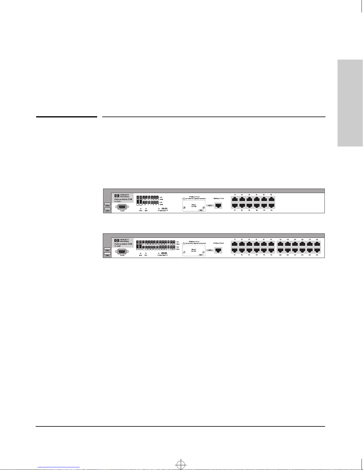
The two switch models are:
1
Introducing the HP ProCurve
Switch 212M and 224M
Throughout this manual, these switches will be abbreviated as the Switch
212M and 224M, or, when common characteristics are being described, as the
Switch 212M/224M.
The Switch 212M and 224M have twelve and twenty-four 10Base-T ports,
respectively, and two 100Base-T ports: one fixed 10/100Base-TX RJ-45 port
and one transceiver slot for installing an HP 10/100Base-TX or 100Base-FX
Transceiver Module.
With these switches you can build a switched network infrastructure by
connecting the switches to hubs, other switches, or routers, or you can
connect computers, printers, and servers to these switches to provide dedicated bandwidth to those devices.
This chapter describes your Switch 212M/224M including:
■ Front and back of the switches
■ Features
■ Switch operation overview
1-1
Srahw.book : SRAHW1.FM Page 2 Tuesday, June 30, 1998 1:50 PM
Introducing the HP ProCurve Switch 212M and 224M
Front of the Switches
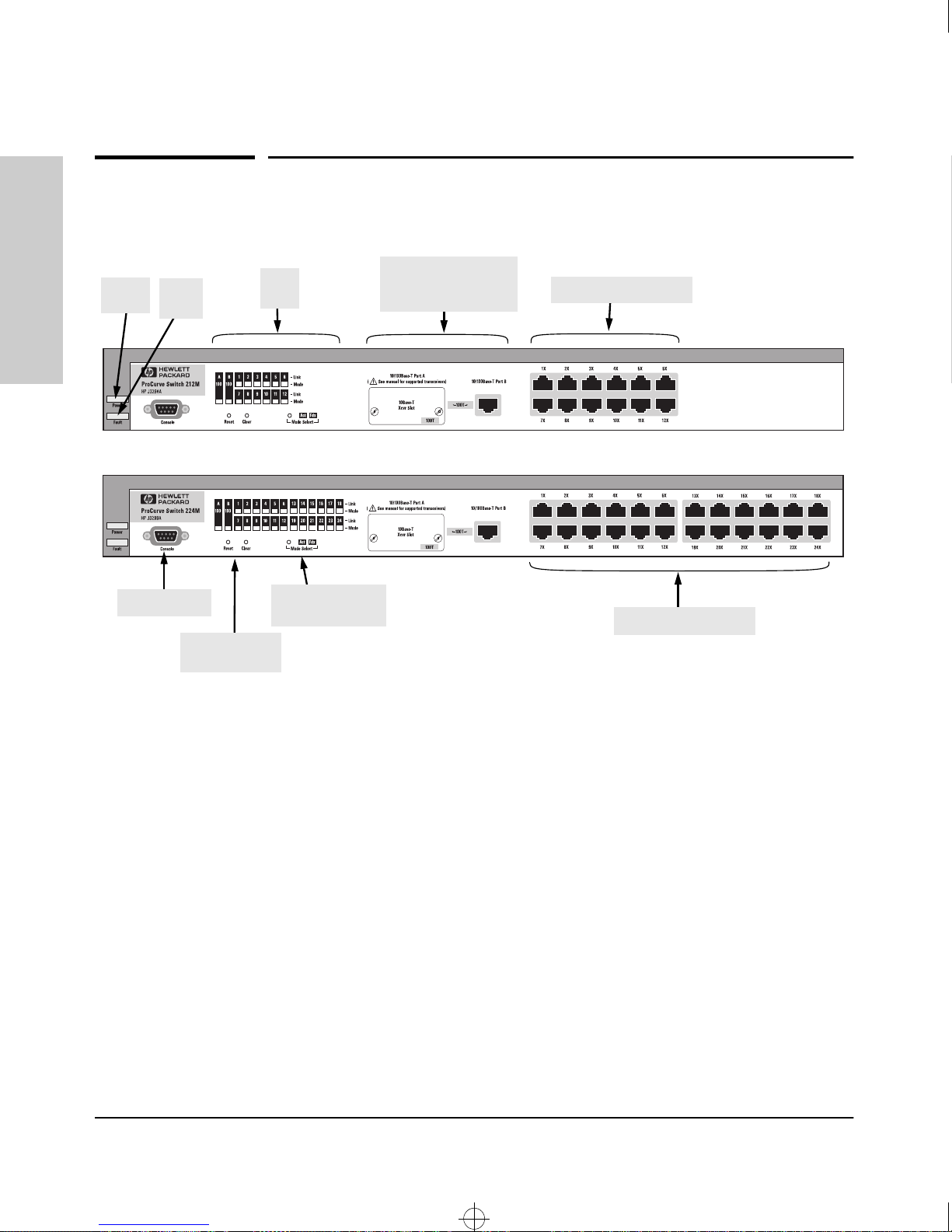
Front of the Switches
Power
LED
Switch 212M and 224M
Introducing the HP ProCurve
Console port
Fault
LED
Reset and Clear
buttons
Port
LEDs
Mode button and
indicator LEDs
10/100Base-T ports:
- one transceiver slot
- one fixed RJ-45
10Base-T RJ-45 ports
10Base-T RJ-45 ports
1-2
Network Ports
■ 12 or 24 10Base-T RJ-45 ports
■ one fixed 10/100Base-TX RJ-45 port
■ one 100Base-T transceiver slot for installing an HP 10/100Base-TX or
100Base-FX transceiver
All the fixed twisted-pair ports are wired as MDI-X. Therefore, to connect end
nodes or other MDI-type devices to these ports, use “straight-through” twistedpair cable; to connect hubs, switches, or other MDI-X-type devices to these
ports, use “crossover” twisted-pair cable. See appendix B, “Cables and
Connectors” for descriptions of these cables.
The cabling to the transceiver port depends on the type of transceiver
installed. For more information, refer to the manual that came with the
transceiver.
Srahw.book : SRAHW1.FM Page 3 Tuesday, June 30, 1998 1:50 PM
Introducing the HP ProCurve Switch 212M and 224M
Front of the Switches
LEDs
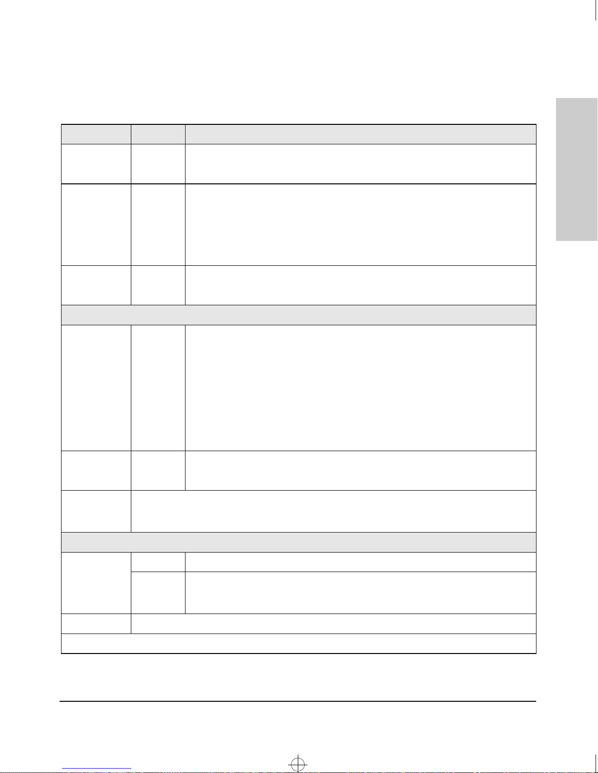
LED State Meaning
Power
(green)
Fault
(orange)
Mode Select
(2 green LEDs)
10/100Base-T Ports
A or B
(green Link
LEDs)
On The switch is receiving power.
Off The switch is NOT receiving power.
Off The normal state. Indicates that there are no fault conditions on the switch.
Flashing* An incorrect transceiver has been installed in the transceiver slot. The transceiver port
LED would flash simultaneously under this condition.
On The switch is in self test after being powered on or reset. If on for a prolonged time,
the switch has failed its self test.
Act Indicates that the port Mode LEDs are displaying network activity information.
Fdx Indicates that the port Mode LEDs are lit for ports that are in Full Duplex Mode.
On Indicates the port is enabled and receiving a link beat signal (for the twisted-pair
transceiver), or a strong enough light level (for the fiber-optic transceiver) from the
connected device.
Off No active network cable is connected to the port, or the port is not receiving link beat
or sufficient light. For port A, it could indicate that there is no transceiver installed. Could
also indicate that the port has been disabled through the switch console, the web agent
interface, or HP TopTools.
Introducing the HP ProCurve
Switch 212M and 224M
Flashing* This condition will only occur on the 100 Mbps port A (the transceiver port), if an
incorrect transceiver is installed in the slot.
100 (green) On The port is operating in 100 Mbps mode.
Off The port is operating in 10 Mbps mode.
Mode (green) Displays network activity information or whether the port is configured for Full Duplex operation
depending on the mode selection. See “Mode Select Button and Indicator LEDs” on the next page
for more information.
10Base-T Ports
Port Number
(green Link
LEDs)
Mode (green) The same meaning as for the 10/100Base-T ports.
* The flashing behavior is an on/off cycle once every 1.6 seconds, approximately.
On Indicates the port is enabled and receiving a link beat signal from the connected device.
Off No active network cable is connected to the port, or the port is not receiving link beat
from the connected node. Could also indicate that the port has been disabled through
the switch console, the web agent interface, or HP TopTools.
1-3
Srahw.book : SRAHW1.FM Page 4 Tuesday, June 30, 1998 1:50 PM
Introducing the HP ProCurve Switch 212M and 224M
Front of the Switches
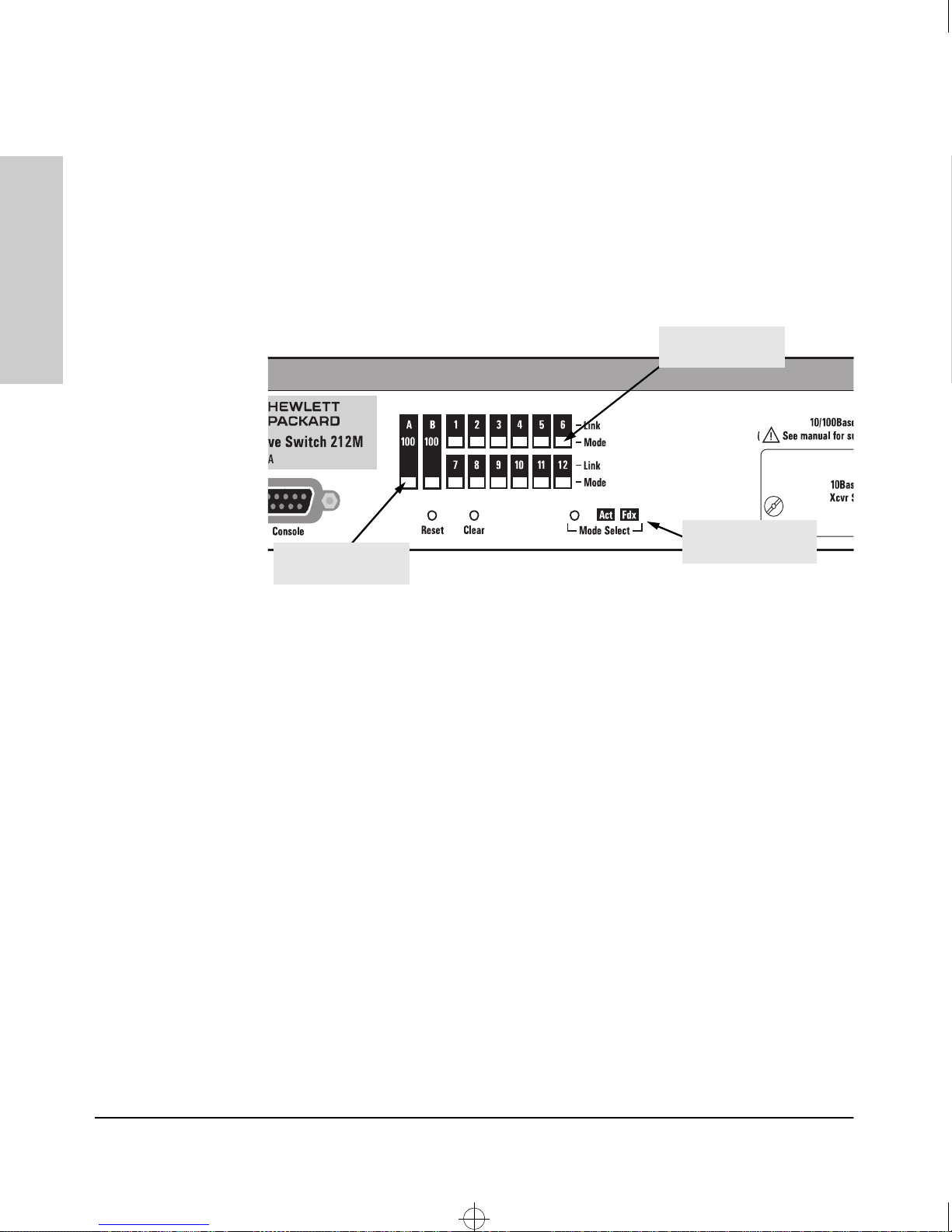
Mode Select Button and Indicator LEDs
To optimize the amount of information that can be displayed for each of the
switch ports without overwhelming you with LEDs, the Switch 212M/224M
uses a Mode LED for each port. The operation of this LED is controlled by the
Mode Select button, and the current setting is indicated by the Mode Indicator
LEDs near the button. Press the button to step from one mode to the next.
Switch 212M and 224M
Introducing the HP ProCurve
Port Mode LED for
10Base-T port
Mode Select button
Port Mode LED for
10/100Base-T port
■ If the Activity (Act) indicator LED is lit, each port Mode LED displays
and Indicator LEDs
activity information for the port—it flickers as network traffic is received
and transmitted through the port.
■ If the Full Duplex (Fdx) indicator LED is lit, the port Mode LEDs light for
those ports that are operating in full duplex.
Console Port
This port is used to connect a console to the switch by using the serial cable
supplied with the switch. This connection is described under “Connecting a
Console to the Switch” in chapter 2, “Installing the Switch 212M and 224M”.
The console can be a PC running a VT-100 terminal emulator, or a VT-100
terminal.
Reset Button
This button is used to reset the switch while it is powered on. This action clears
any temporary error conditions that may have occurred, executes the switch
self test, and resets all network activity counters to zero. The counters are
displayed in the switch console interface, the switch web browser interface,
and through SNMP network management applications, such as HP TopTools
for Hubs & Switches.
1-4
Srahw.book : SRAHW1.FM Page 5 Tuesday, June 30, 1998 1:50 PM
Introducing the HP ProCurve Switch 212M and 224M
Back of the Switches
Clear Button
This button is used for these purposes:
When pressed by itself for at least one second, deletes any switch console
■
access passwords that you may have configured. Use this feature if you
have misplaced the password and need console access.
This button is provided for your convenience, but its presence means
that if you are concerned with the security of the switch configuration
and operation, you should make sure the switch is installed in a secure
location, such as a locked wiring closet.
■ When pressed with the Reset button in a specific pattern, clears any
configuration changes you may have made through the switch console,
the web browser interface, and SNMP management, and restores the
factory default configuration to the switch. For the specific method to
restore the factory default configuration, see “Restoring the Factory
Default Configuration” in chapter 8, “Troubleshooting” or the HP
ProCurve Switch 212M and 224M Management and Configuration
Guide that came with your switch.
Introducing the HP ProCurve
Switch 212M and 224M
Back of the Switches
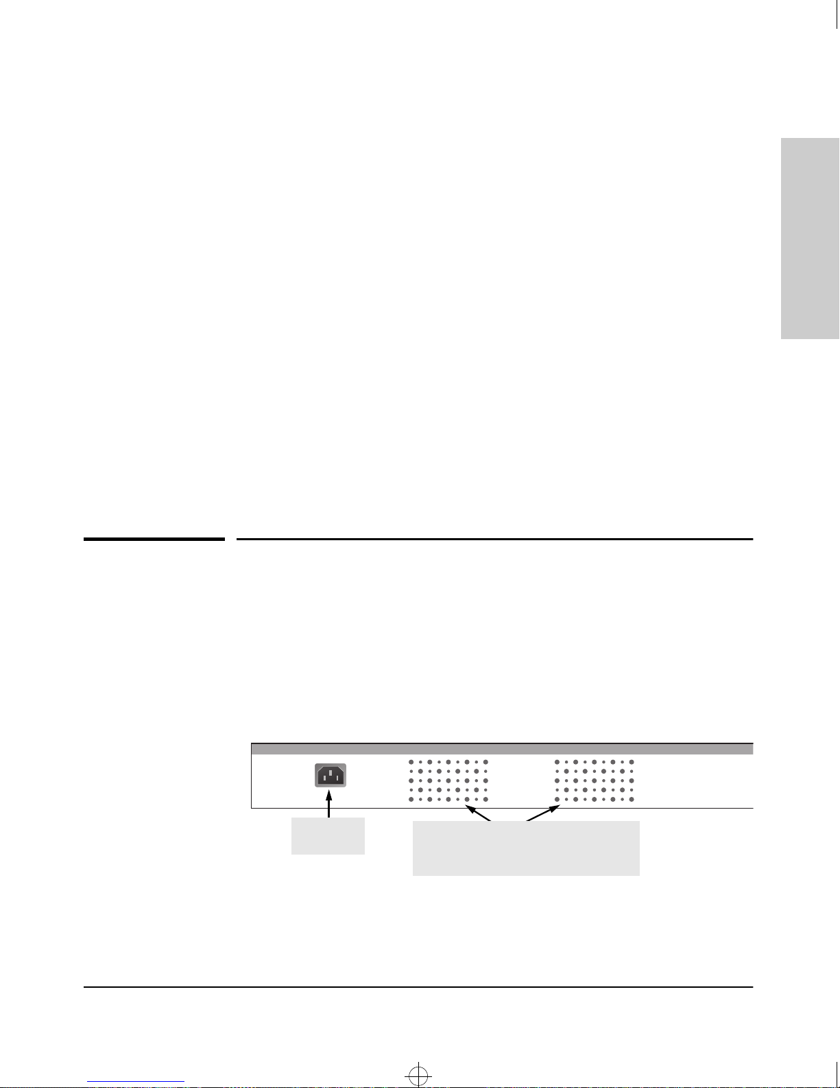
Power Connector
The Switch 212M and Switch 224M do not have a power switch; they are
powered on when connected to an active AC power source. The switches
automatically adjust to any voltage between 100-127 and 200-240 volts and
either 50 or 60 Hz. There are no voltage range settings required.
AC power
connector
cooling vents - make sure these vents and
the ones on the sides of the switch are not
obstructed for proper switch operation
1-5

Srahw.book : SRAHW1.FM Page 6 Tuesday, June 30, 1998 1:50 PM
Introducing the HP ProCurve Switch 212M and 224M
Features
Features
The features of the Switch 212M and 224M include:
■ 12 or 24 Ethernet/10Base-T ports with RJ-45 connectors
■ two IEEE 802.3u 100Base-T compatible ports: one fixed 100Base-TX port
with an RJ-45 connector, and one transceiver slot for either a
Switch 212M and 224M
Introducing the HP ProCurve
10/100Base-TX twisted-pair, or a 100Base-FX fiber-optic transceiver
■ plug-and-play networking—all ports are enabled—just connect the
network cables to active network devices and your switched network is
operational
■ automatic learning of the network addresses in the switch’s 2048-address
forwarding table, with configurable address aging value
■ configurable full-duplex operation of the 10 Mbps and 100 Mbps ports
■ easy management of the switch through several available interfaces:
• web browser interface—an easy to use built-in graphical interface
that can be accessed from supported versions of Microsoft Internet
Explorer or Netscape Navigator web browsers
• switch console interface—a full featured, easy to use, VT-100
terminal interface that is especially good for out-of-band switch
management, or for telnet access to the switch
• HP TopTools for Hubs & Switches—an SNMP-based graphical
interface that is used to manage your entire network, including your
new switch
■ support for the Spanning Tree Protocol to eliminate network loops
■ support for features that help enhance network performance: IGMP and
flow control
1-6

Srahw.book : SRAHW1.FM Page 7 Tuesday, June 30, 1998 1:50 PM
Introducing the HP ProCurve Switch 212M and 224M
Switch Operation Overview
Address Table Operation
Address Learning. As devices are connected to the switch ports, either
directly or through hubs or other switches that are connected to the switch,
the MAC addresses of those devices are learned automatically and stored in
the Switch 212M/224M’s 2048-entry address table. The switch also identifies
the number of the port on which each address is learned so it knows the
network location of each device.
Forwarding, Filtering, Flooding. When the switch receives a packet, it
determines the destination address and looks for the address in the address
table. Based on the port location of that address, the switch then determines
whether to forward, filter-out, or flood the packet.
■ forward - if the destination address is on a different port than the one on
which the packet was received, the packet is forwarded to the destination
port and on to the destination device.
■ filter out - if the destination address is on the same port as the one on
which the packet was received, the packet is filtered out. The switch
thereby isolates local traffic so the rest of the network connected to the
switch does not lose bandwidth dealing with unnecessary traffic.
■ flood - whenever a new destination address is found in a packet received
on one of the switch ports, the destination address will not yet be in the
switch’s address table and the Switch 212M/224M cannot know whether
to forward or filter out the packet. In this case, it sends the packet to all
the other ports. This is referred to as “flooding”. When the destination
device receives the packet, it replies, and the switch learns the new
address from the reply packet. Then, all future packets destined for that
address are forwarded or filtered out appropriately.
Switch Operation Overview
Introducing the HP ProCurve
Switch 212M and 224M
Network Moves and Changes. When devices are moved in the network,
and become connected to a different switch port, the Switch 212M/224M
automatically recognizes the change and updates the address table with the
new port location of the device. Communication with the device is automatically maintained, without any address table manipulation being required.
1-7

Srahw.book : SRAHW1.FM Page 8 Tuesday, June 30, 1998 1:50 PM
Introducing the HP ProCurve Switch 212M and 224M
Switch Operation Overview
Simultaneous Network Communications
In addition to traffic isolation benefits provided by the Switch 212M/224M
address table operation, the switch also enhances network performance
because it can conduct multiple, simultaneous network connections. Instead
of sharing the network bandwidth, as in connections to a hub, each connection
has its own 10 Mbps or 100 Mbps bandwidth to use.
Switch 212M and 224M
Introducing the HP ProCurve
1-8

Srahw.book : SRAHW2.FM Page 1 Tuesday, June 30, 1998 1:50 PM
Installing the Switch 212M and 224M
The HP Switch 212M and 224M are easy to install. They come with an
accessory kit that includes the brackets for mounting the switches in a
standard 19-inch telco rack, or equipment cabinet, or on a wall, and rubber
feet so the switches can be securely located on any horizontal surface. The
brackets are designed to allow mounting the switches in a variety of
orientations.
This chapter shows you how to install your Switch 212M or 224M.
2
Installing the Switch 212M
Included Parts
The Switch 212M and 224M have the following components shipped with
them:
■ HP ProCurve Switch 212M and 224M Installation Guide (5967-2145),
this manual
■ HP ProCurve Switch 212M and 224M Management and Configuration
Guide (5967-2146)
■
HP TopTools for Hub & Switches - CD-ROM and booklet
Customer Support/Warranty booklet
■
■ Accessory kit (5064-2085):
• two mounting brackets
• four 10 mm M4 screws to attach the mounting brackets to the switch
• four 5/8-inch number 12-24 screws to attach the brackets to a rack
• four rubber feet
■ Console cable
Power cord, one of the following:
■
and 224M
Australia/New Zealand
United Kingdom
China
Continental Europe
Denmark
Japan
Switzerland
United States/Canada/Mexico
(8120-6803)
(8120-6801)
(8120-8377)
(8120-6802)
(8120-6806)
(8120-6804)
(8120-6807)
(8120-6805)
2-1

Srahw.book : SRAHW2.FM Page 2 Tuesday, June 30, 1998 1:50 PM
Installing the Switch 212M and 224M
Installation Procedures
Installation Procedures
Summary
Follow these easy steps to install your switch. The rest of this chapter provides
details on these steps.
1. Prepare the installation site. Make sure that the physical environment
into which you will be installing the switch is properly prepared including
having the correct network cabling ready to connect to the switch, and
having a good location for the switch. Please see page 2-3 for some
installation precautions.
and 224M
Installing the Switch 212M
2. (Optional) Install a transceiver. The Switch 212M/224M has a slot for
installing a 100Base-T twisted-pair or fiber-optic transceiver module. It
may be easier to install the transceiver before mounting the switch. The
switch should be powered off when installing or removing transceivers.
3. Verify that the switch passes self test. This is a simple process of
plugging the switch into a power source and observing that the LEDs on
the switch’s front panel show correct switch operation. See page 2-7.
4. Mount the switch. The Switch 212M/224M can be mounted in a 19-inch
telco rack or equipment cabinet, on a wall, or on a horizontal surface.
5. Connect power to the switch. Once the switch is mounted, plug it in to
the nearby main power source.
6. Connect the network devices. Using the appropriate network cables,
connect the computers, servers, printers, and other network devices to
the switch ports.
7. (Optional) Connect a console to the switch for configuration. In
the factory default configuration, the Switch 212M/224M operates,
without any changes, as a multiport transparent bridge. You may wish to
modify the switch’s configuration, for example, to configure an IP address
so it can be managed using a web browser or from an SNMP network
management station or through a Telnet session to the switch console. An
IP address can be configured on the switch, and other configuration
changes can be made easily by using the included console cable to connect
a PC to the switch’s console port.
At this point, the switch is fully installed and your network should be up and
running. See the rest of this chapter if you need more detailed information on
any of these installation steps.
2-2

Srahw.book : SRAHW2.FM Page 3 Tuesday, June 30, 1998 1:50 PM
Installing the Switch 212M and 224M
Installation Precautions:
Follow these precautions when installing your HP Switch 212M or
Switch 224M.
Installation Procedures
Warning
Cautions
The rack or cabinet should be adequately secured to prevent it from
becoming unstable and/or falling over.
Devices installed in a rack or cabinet should be mounted as low as
possible, with the heaviest device at the bottom and progressively
lighter devices installed above.
■ Make sure that the power source circuits are properly grounded,
then use the power cord supplied with the switch to connect it to the
power source.
If your installation requires a different power cord than the one
supplied with the switch, be sure to use a power cord displaying
the mark of the safety agency that defines the regulations for power
cords in your country. The mark is your assurance that the power
cord can be used safely with the switch.
■ Ensure that the switch does not overload the power circuits, wiring,
and over-current protection. To determine the possibility of overloading
the supply circuits, add together the ampere ratings of all devices
installed on the same circuit as the switch and compare the total with
the rating limit for the circuit. The maximum ampere ratings are usually
printed on the devices near the AC power connectors.
■ Do not install the switch in an environment where the operating
ambient temperature might exceed 55°C (131°F).
■ Make sure the air flow around the sides and back of the switch is
not restricted.
■ Make sure that if no module is installed in the module slot, the cover
plate is installed to cover the slot. A cover plate is required for safe
operation, and to ensure proper switch cooling.
Installing the Switch 212M
and 224M
2-3

Srahw.book : SRAHW2.FM Page 4 Tuesday, June 30, 1998 1:50 PM
Installing the Switch 212M and 224M
Installation Procedures
1. Prepare the Installation Site
■ Cabling Infrastructure - Ensure that the cabling infrastructure meets
the necessary network specifications. See the following table for cable
types and lengths, and see appendix B, “Cables and Connectors” for more
information:
Table 2-1. Summary of Cable Types to Use with the Switch
Port Type Cable Type Length Limits
and 224M
Installing the Switch 212M
10Base-T category 3, 4, or 5, 100 ohm
unshielded twisted-pair
(UTP)
100Base-TX category 5, 100-ohm UTP or
shielded twisted-pair (STP)
100Base-FX 1300 nm multi-mode fiber-
optic cables that are fitted
with SC connectors, and
conform to ISO/IEC 793-2
type B1 and ITU-T G.652
standards
■ Installation Location - Before installing the switch, plan its location and
• category 3, 4, or 5 - 100 meters
Note: For connecting these ports to end
nodes or other MDI ports, use “straightthrough” cable; for connecting to MDI-X
ports on hubs or other switches, use
“crossover” cable.
100 meters
(See Note above on use of “straight-
through” and “cross-over” cables.)
• 412 meters for half-duplex connections
• 2 kilometers for full-duplex connections
orientation relative to other devices and equipment. In the front of the
switch, leave at least 3 inches (7.6 cm) of space for the twisted-pair and
fiber-optic cabling. In the back, leave at least 1 1/2 inches (3.8 cm) of space
for the power cord.
2-4
Srahw.book : SRAHW2.FM Page 5 Tuesday, June 30, 1998 1:50 PM
Installing the Switch 212M and 224M
2. Install An Optional Transceiver
Install optional transceiver modules into the transceiver slot by following the
instructions in the manuals that accompany these products.
The slot cover can be removed with either a flat-bladed or Torx T-10 screwdriver. Retain the slot cover for future use.
Installation Procedures
Caution
To avoid damage to circuitry in the switch and any modules, always
unplug the power from the switch before installing or removing a
transceiver module into the transceiver slot, and when removing any
modules.
If you do not install an optional transceiver, make sure that the cover plate is
still attached over the slot for safe operation and proper switch cooling.
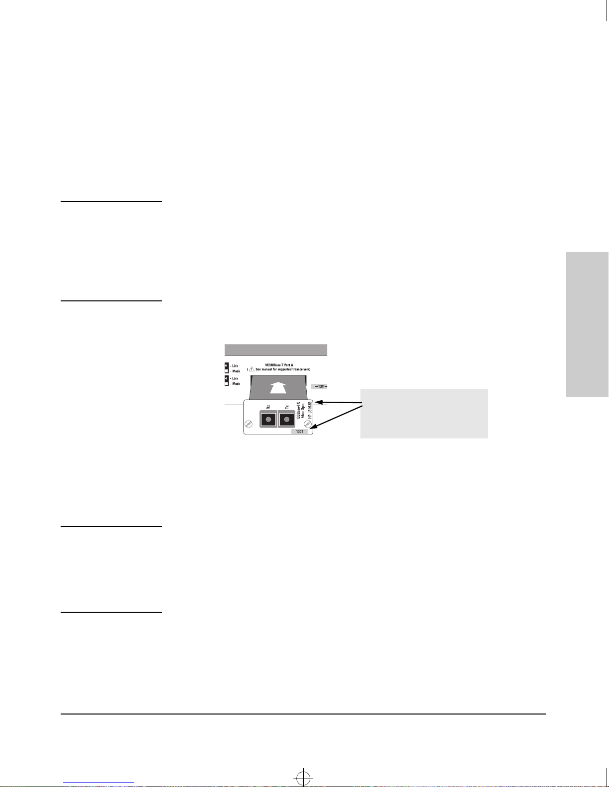
Installing Transceivers
Blue color bar with “100T” in it,
and the correct model number
identifies a correct transceiver
for the Switch 212M and 224M
Supported Transceiver Models: Install either of these HP 100Base-T
transceiver modules into the transceiver slot:
- HP J3192C 10/100Base-TX Twisted-Pair Transceiver Module
- HP J3193B 100Base-FX Fiber-Optic Transceiver Module
Installing the Switch 212M
and 224M
Caution
Make sure you install only the “B” model or later version of the
100Base-FX Fiber Optic transceiver module, and the “C” model or
later version of the 10/100Base-TX Twisted-Pair transceiver module
into the Switch 212M/224M.
Do not install any 100VG transceiver modules in this slot.
2-5
 Loading...