

HP ProCurve 2224 Installation Manual
HP ProCurve Switches and Hubs
HP ProCurve Switch 2224
Installation Guide
Less Work, More Network
http://www.hp.com/go/procurve


Ice.book Page i Monday, January 11, 1999 5:23 PM
HP ProCurve
Switch 2224
Installation Guide

Ice.book Page ii Monday, January 11, 1999 5:23 PM
© Copyright 1998 Hewlett-Packard Company
All Rights Reserved.
This document contains information which is protected by
copyright. Reproduction, adaptation, or translation without
prior permission is prohibited, except as allowed under the
copyright laws.
Publication Number
J4095-90001
December 1998
Applicable Products
HP ProCurve Switch 2224 (HP J4095A)
Disclaimer
The information contained in this document is subject to
change without notice.
HEWLETT-PACKARD COMPANY MAKES NO WARRANTY
OF ANY KIND WITH REGARD TO THIS MATERIAL,
INCLUDING, BUT NOT LIMITED TO, THE IMPLIED
WARRANTIES OF MERCHANTABILITY AND FITNESS
FOR A PARTICULAR PURPOSE. Hewlett-Packard shall not
be liable for errors contained herein or for incidental or
consequential damages in connection with the furnishing,
performance, or use of this material.
Hewlett-Packard assumes no responsibility for the use or
reliability of its software on equipment that is not furnished
by Hewlett-Packard.
Warranty
See the Customer Support/Warranty booklet included with
the product.
A copy of the specific warranty terms applicable to your
Hewlett-Packard products and replacement parts can be
obtained from your HP Sales and Service Office or
authorized dealer.
Safety
Before installing and operating this product, please read the
“Installation Precautions” in chapter 2, “Installing the Switch
2224”, and the safety statements in appendix C, “Safety and
EMC Regulatory Statements”.
Hewlett-Packard Company
8000 Foothills Boulevard, m/s 5552
Roseville, California 95747-5552
http://www.hp.com/go/procurve

Ice.book Page iii Monday, January 11, 1999 5:23 PM
Contents
1 Introducing the HP Switch 2224
Front of the Switch . . . . . . . . . . . . . . . . . . . . . . . . . . . . . . . . . . . . . . . . . . . . 1-2
Network Ports . . . . . . . . . . . . . . . . . . . . . . . . . . . . . . . . . . . . . . . . . . . . . . 1-2
Reset Button . . . . . . . . . . . . . . . . . . . . . . . . . . . . . . . . . . . . . . . . . . . . . . . 1-2
LEDs . . . . . . . . . . . . . . . . . . . . . . . . . . . . . . . . . . . . . . . . . . . . . . . . . . . . . . 1-3
Mode Select Button and Indicator LEDs . . . . . . . . . . . . . . . . . . . . . . . . 1-4
Port 1 Indicator LED . . . . . . . . . . . . . . . . . . . . . . . . . . . . . . . . . . . . . . . . . 1-4
Back of the Switch . . . . . . . . . . . . . . . . . . . . . . . . . . . . . . . . . . . . . . . . . . . . 1-5
Power Connector . . . . . . . . . . . . . . . . . . . . . . . . . . . . . . . . . . . . . . . . . . . 1-5
Features . . . . . . . . . . . . . . . . . . . . . . . . . . . . . . . . . . . . . . . . . . . . . . . . . . . . . . 1-6
Switch Operation Overview . . . . . . . . . . . . . . . . . . . . . . . . . . . . . . . . . . . . 1-6
Address Table Operation . . . . . . . . . . . . . . . . . . . . . . . . . . . . . . . . . . . . . 1-6
Simultaneous Network Communications . . . . . . . . . . . . . . . . . . . . . . . 1-7
2 Installing the Switch 2224
Included Parts . . . . . . . . . . . . . . . . . . . . . . . . . . . . . . . . . . . . . . . . . . . . . . . . 2-1
Installation Procedures . . . . . . . . . . . . . . . . . . . . . . . . . . . . . . . . . . . . . . . . 2-2
Summary . . . . . . . . . . . . . . . . . . . . . . . . . . . . . . . . . . . . . . . . . . . . . . . . . . . 2-2
Installation Precautions . . . . . . . . . . . . . . . . . . . . . . . . . . . . . . . . . . . . . . 2-3
1. Prepare the Installation Site . . . . . . . . . . . . . . . . . . . . . . . . . . . . . . . . 2-4
2. Install An Optional Transceiver . . . . . . . . . . . . . . . . . . . . . . . . . . . . . . 2-5
3. Verify the Switch Operates Correctly . . . . . . . . . . . . . . . . . . . . . . . . . 2-6
4. Mount the Switch . . . . . . . . . . . . . . . . . . . . . . . . . . . . . . . . . . . . . . . . . 2-8
5. Connect the Switch to a Power Source . . . . . . . . . . . . . . . . . . . . . . 2-11
6. Connect the Network Cables . . . . . . . . . . . . . . . . . . . . . . . . . . . . . . . 2-12
Sample Network Topologies . . . . . . . . . . . . . . . . . . . . . . . . . . . . . . . . . . 2-13
As a Desktop Switch . . . . . . . . . . . . . . . . . . . . . . . . . . . . . . . . . . . . . . . . 2-13
As a Segment Switch . . . . . . . . . . . . . . . . . . . . . . . . . . . . . . . . . . . . . . . . 2-14
Connecting to a Backbone Switch . . . . . . . . . . . . . . . . . . . . . . . . . . . . 2-15
iii

Ice.book Page iv Monday, January 11, 1999 5:23 PM
3 Troubleshooting
Basic Troubleshooting Tips . . . . . . . . . . . . . . . . . . . . . . . . . . . . . . . . . . . . 3-1
Diagnosing with the LEDs . . . . . . . . . . . . . . . . . . . . . . . . . . . . . . . . . . . . . 3-3
Hardware Diagnostic Tests . . . . . . . . . . . . . . . . . . . . . . . . . . . . . . . . . . . . 3-5
Testing the Switch by Resetting It . . . . . . . . . . . . . . . . . . . . . . . . . . . . . 3-5
Testing Twisted-Pair Cabling . . . . . . . . . . . . . . . . . . . . . . . . . . . . . . . . . . 3-5
Testing End-to-End Network Communications . . . . . . . . . . . . . . . . . . 3-6
HP Customer Support Services . . . . . . . . . . . . . . . . . . . . . . . . . . . . . . . . . 3-6
A Specifications
Physical . . . . . . . . . . . . . . . . . . . . . . . . . . . . . . . . . . . . . . . . . . . . . . . . . . A-1
Electrical . . . . . . . . . . . . . . . . . . . . . . . . . . . . . . . . . . . . . . . . . . . . . . . . . A-1
Environmental . . . . . . . . . . . . . . . . . . . . . . . . . . . . . . . . . . . . . . . . . . . . A-1
Acoustic . . . . . . . . . . . . . . . . . . . . . . . . . . . . . . . . . . . . . . . . . . . . . . . . . . A-1
Connectors . . . . . . . . . . . . . . . . . . . . . . . . . . . . . . . . . . . . . . . . . . . . . . . . A-2
Safety . . . . . . . . . . . . . . . . . . . . . . . . . . . . . . . . . . . . . . . . . . . . . . . . . . . . A-2
B Cables and Connectors
Twisted-Pair Cable/Connector Pin-Outs . . . . . . . . . . . . . . . . . . . . . . . B-1
Twisted-Pair Cable for Switch (MDI-X) to
Computer (MDI) Network Connection . . . . . . . . . . . . . . . . . . . . . . . . B-2
Twisted-Pair Cable for Switch (MDI-X) to
Hub or Switch (MDI-X) Network Connection . . . . . . . . . . . . . . . . . . . B-3
Twisted-Pair Cable Pin Assignments . . . . . . . . . . . . . . . . . . . . . . . . . . B-4
Fiber-Optic Cables . . . . . . . . . . . . . . . . . . . . . . . . . . . . . . . . . . . . . . . . . . . B-5
100Base-FX Transceiver Port . . . . . . . . . . . . . . . . . . . . . . . . . . . . . . . . B-5
C Safety and EMC Regulatory Statements
Safety Information . . . . . . . . . . . . . . . . . . . . . . . . . . . . . . . . . . . . . . . . . . . C-1
EMC Regulatory Statements . . . . . . . . . . . . . . . . . . . . . . . . . . . . . . . . . . C-8
Index
iv
Ice.book Page 1 Monday, January 11, 1999 5:23 PM
Introducing the HP Switch 2224
The HP ProCurve Switch 2224 is a multiport switch that can be used to build
high-performance switched workgroup networks. This switch is a store-andforward device that offers low latency for high-speed networking.
HP ProCurve Switch 2224 (HP J4095A)
1
Introducing the HP Switch
2224
Throughout this manual, this switch will be abbreviated as the Switch 2224.
The Switch 2224 has 24 auto-sensing 10/100Base-T RJ-45 ports, and a slot for
installing an HP 100Base-FX fiber-optic transceiver.
With this switch you can build a switched network infrastructure by
connecting it to hubs, other switches, or routers; or you can connect directly
to computers, printers, and servers to provide dedicated bandwidth to those
devices.
This chapter describes your HP Switch 2224 including:
■ Front and back of the switch
■ Features
■ Switch operation overview
1-1
Ice.book Page 2 Monday, January 11, 1999 5:23 PM
Introducing the HP Switch 2224
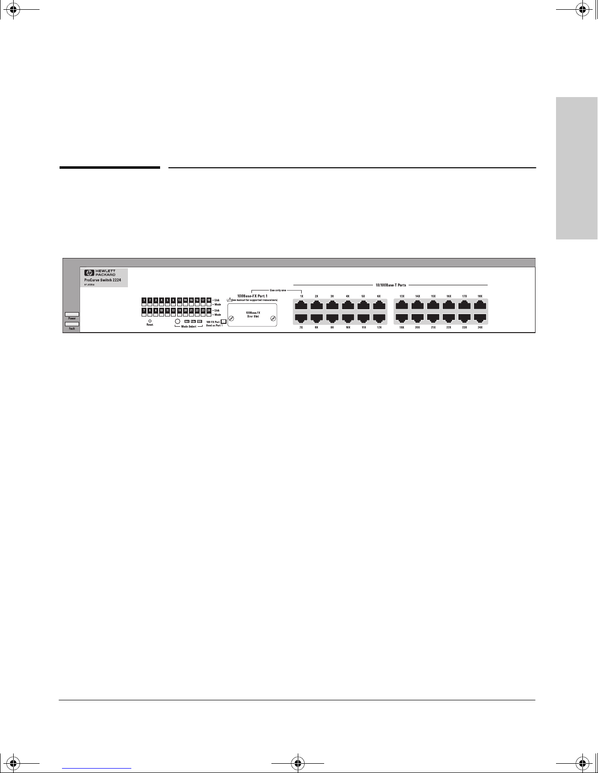
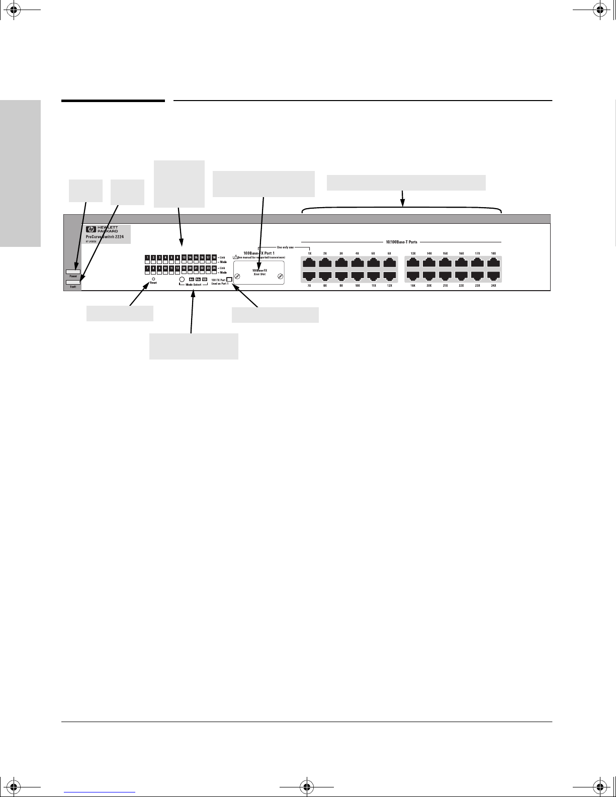
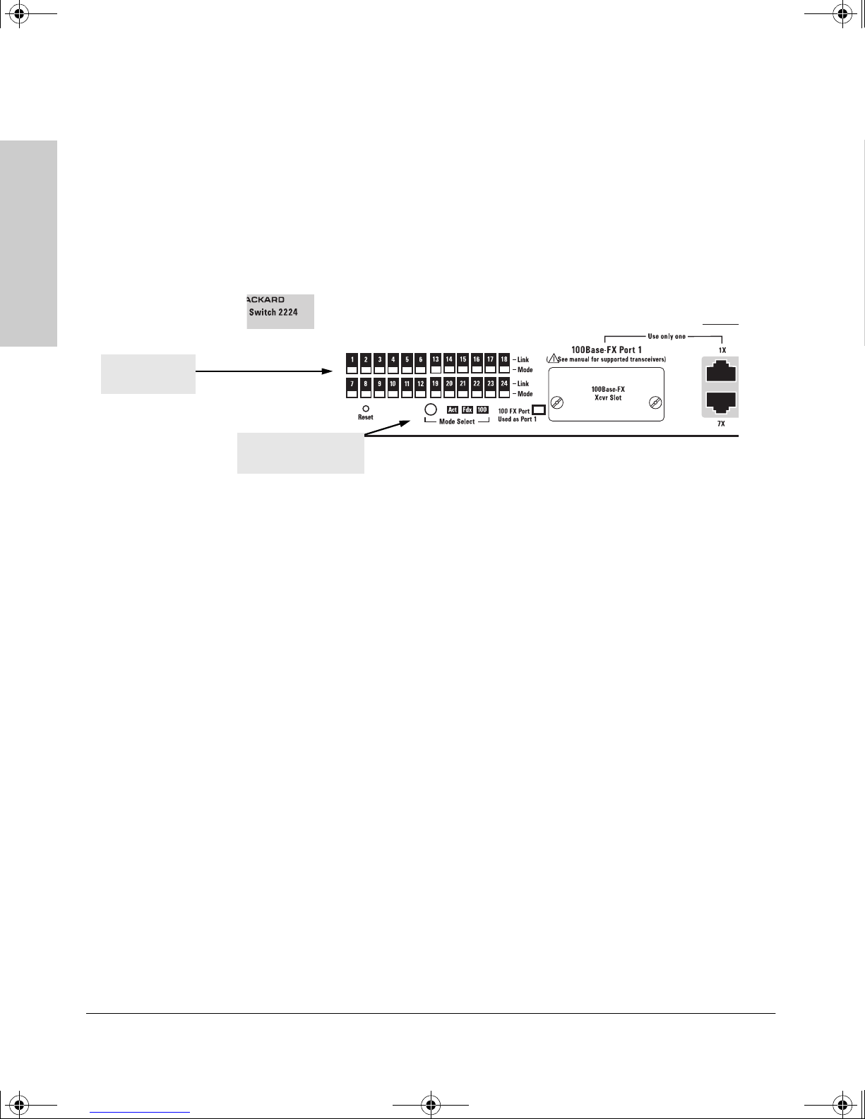
Front of the Switch
Link and
2224
Power
LED
Fault
LED
Mode LEDs
for each
Introducing the HP Switch
Front of the Switch
Slot for
100Base-FX Transceiver
port
10/100Base-TX RJ-45 ports
Reset button
Port 1 indicator LED
Mode Select button
and indicator LEDs
Network Ports
■ 24 auto-sensing 10/100Base-TX ports
■ one transceiver module slot for installing the 100Base-FX transceiver
module (HP J3193B)
Reset Button
This button is used to reset the switch while it is powered on. This action clears
any temporary error conditions that may have occurred, and executes the
switch self test.
1-2
Ice.book Page 3 Monday, January 11, 1999 5:23 PM
Introducing the HP Switch 2224
Front of the Switch
LEDs
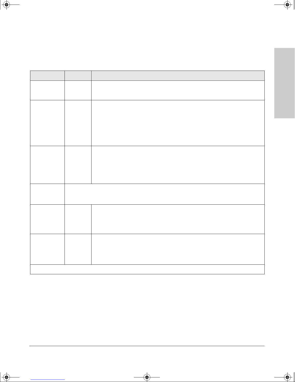
Table 1-1. Switch LEDs
Switch LEDs State Meaning
Power
(green)
Fault
(orange)
Link
(green –
overlaid with
the port
number)
Mode
(green)
On The switch is receiving power.
Off The switch is NOT receiving power.
Off The normal state; indicates that there are no fault conditions on the switch.
Blinking
On On briefly after the switch is powered on or reset, at the beginning of switch self test.
On Indicates the port is enabled and receiving a link beat signal (for the twisted-pair ports),
Off One of these conditions exists:
Displays network activity information, or whether the port is configured for full-duplex operation, or
100 Mbps operation depending on the mode selected. See “Mode Select Button and Indicator LEDs”
on the next page for more information.
†
A fault has occurred on the switch, or the transceiver module (if installed). If the
transceiver is having the problem, the Port 1 Link LED will blink simultaneously.
If on for a prolonged time, the switch has a hardware failure, or has failed its self test.
See chapter 3, “Troubleshooting” for more information.
or a strong enough light level (for the fiber-optic ports) from the connected device.
• no active network cable is connected to the port
• the port is not receiving link beat or sufficient light
Introducing the HP Switch
2224
Mode Select
indicators
(3 green LEDs)
Port 1
indicator LED
(green)
†
The blinking behavior is an on/off cycle once every 1.6 seconds, approximately.
Act Indicates that the port Mode LEDs are displaying network activity information.
Fdx Indicates that the port Mode LEDs are lit for ports that are in Full Duplex Mode.
100 Indicates that the port Mode LEDs are lit for ports that are operating at 100 Mbps.
On Indicates that a transceiver module is installed in the slot, and the switch is using the
transceiver as switch Port 1.
Off A transceiver module is not installed in the switch, and the fixed Port 1 RJ-45 connector
is being used as switch Port 1.
1-3
Ice.book Page 4 Monday, January 11, 1999 5:23 PM
Introducing the HP Switch 2224
Front of the Switch
2224
Introducing the HP Switch
Mode LEDs
(one per port)
Mode Select Button and Indicator LEDs
To optimize the amount of information that can be displayed for each of the
switch ports without overwhelming you with LEDs, the Switch 2224 uses a
Mode LED for each port. The operation of this LED is controlled by the Mode
Select button, and the current setting is indicated by the Mode indicator LEDs
near the button. Press the button to step from one mode to the next.
Mode Select button
and indicator LEDs
■ If the Activity (Act) indicator LED is lit, the Mode LED for each port
displays activity information for the port—it flickers as network traffic is
received and transmitted through the port.
■ If the Full Duplex (Fdx) indicator LED is lit, the Mode LEDs light for those
ports that are operating in full duplex.
■ If the 100 Mbps (100) indicator LED is lit, the Mode LEDs light for those
ports that are operating at 100 Mbps.
Port 1 Indicator LED
The LED labeled “100FX Port used as Port 1” indicates which of the switch
ports, the transceiver module or the fixed RJ-45 connector is being used as
the switch Port 1. Only one of these ports can be active at any time. If a
transceiver module is installed, it will automatically be selected by the switch
to be used for Port 1, and the LED will be lit, even if there is no active fiberoptic cable connected to the transceiver.
If a non-supported transceiver is installed in the switch, for example a
100Base-TX twisted-pair transceiver, this LED remains off.
1-4
Ice.book Page 5 Monday, January 11, 1999 5:23 PM
Introducing the HP Switch 2224
Back of the Switch
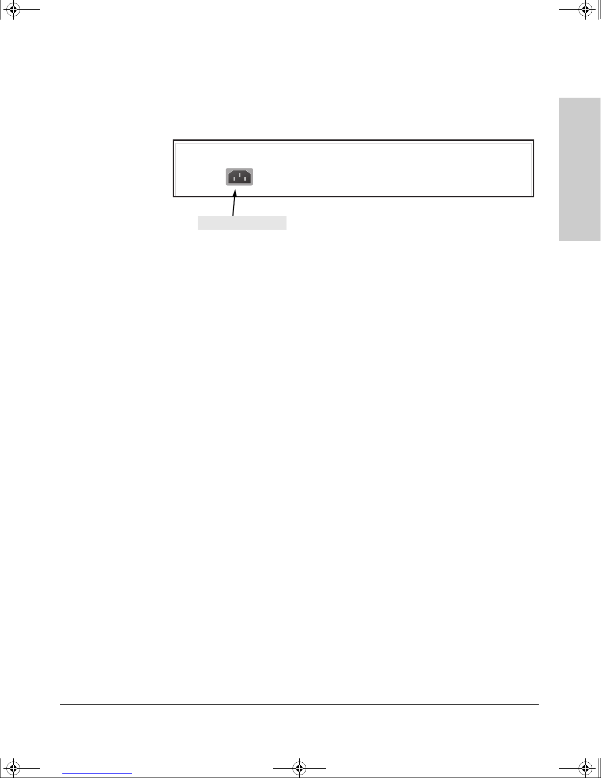
Back of the Switch
.
AC power connector
Power Connector
The Switch 2224 does not have a power switch; it is powered on when
connected to an active AC power source. The switch automatically adjusts to
any voltage between 100-127 and 200-240 volts and either 50 or 60 Hz. There
are no voltage range settings required.
Introducing the HP Switch
2224
1-5

Ice.book Page 6 Monday, January 11, 1999 5:23 PM
Introducing the HP Switch 2224
Features
2224
Introducing the HP Switch
Features
The features of the Switch 2224 include:
■ 24 auto-sensing 10/100Base-TX RJ-45 ports
■ a slot for installing an HP 100Base-FX Transceiver Module (HP J3193B)
■ plug-and-play networking—all ports are enabled—just connect the
network cables to active network devices and your switched network is
operational
■ automatic learning of the hardware addresses in the switch’s 12000-entry
address forwarding table
■ auto-negotiation of half/full duplex on all ports
■ auto-negotiation of flow control for ports operating at full duplex
Switch Operation Overview
Address Table Operation
Address Learning. As devices are connected to the switch ports, either
directly or through hubs or other switches that are connected to the switch,
the MAC addresses of those devices are learned automatically and stored in
the Switch 2224’s 12000-entry address table. The switch also identifies the
number of the port on which each address is learned so it knows the relative
network location of each device.
Forwarding, Filtering, Flooding. When the switch receives a packet, it
determines the destination address, and looks for the address in the address
table. Based on the port location of that address, the switch then determines
whether to forward, filter-out, or flood the packet.
■ forward - if the destination address is on a different port than the one on
which the packet was received, the packet is forwarded to the destination
port and on to the destination device.
■ filter out - if the destination address is on the same port as the one on
which the packet was received, the packet is filtered out. The switch
thereby isolates local traffic so the rest of the network connected to the
switch does not use bandwidth dealing with unnecessary traffic.
1-6

Ice.book Page 7 Monday, January 11, 1999 5:23 PM
Introducing the HP Switch 2224
Switch Operation Overview
■ flood - whenever a new destination address is found in a packet received
on a port, the destination address will not yet be in the switch’s address
table and the Switch 2224 cannot know whether to forward or filter out
the packet. In this case, it sends the packet to all the other switch ports.
This is referred to as “flooding”. When the destination device receives the
packet, it replies, and the switch learns the new address from the reply
packet. Then, all future packets destined for that address are forwarded
or filtered out appropriately.
Network Moves and Changes. When devices are moved in the network,
and become connected to a different switch port, the Switch 2224 automatically recognizes the change and updates the address table with the new port
location of the device. Communication with the device is automatically maintained, without any address table manipulation being required.
Simultaneous Network Communications
As a part of the traffic isolation benefits provided by the Switch 2224 address
table operation, the switch enhances network performance because it can
conduct multiple, simultaneous network connections. Instead of sharing the
network bandwidth, as in connections to a hub, each connection has its own
10 Mbps, or 100 Mbps.
Introducing the HP Switch
2224
1-7

Ice.book Page 8 Monday, January 11, 1999 5:23 PM

Ice.book Page 1 Monday, January 11, 1999 5:23 PM
Installing the Switch 2224
The HP Switch 2224 is easy to install. It comes with an accessory kit that
includes the brackets for mounting the switch in a standard 19-inch telco rack
or an equipment cabinet, or on a wall, and with rubber feet that can be attached
so the switch can be securely located on a horizontal surface. The brackets
are designed to allow mounting the switch in a variety of orientations.
This chapter shows you how to install your Switch 2224.
2
Installing the Switch 2224
Included Parts
The Switch 2224 has the following components shipped with it:
■ HP ProCurve Switch 2224 Installation Guide (J4095-90001), this manual
■ Customer Support/Warranty booklet
■ Accessory kit (5064-4280)
• two mounting brackets
• four 10 mm M4 screws to attach the mounting brackets to the switch
• four 5/8-inch number 12-24 screws to attach the switch to a rack
• four rubber feet
■ Power cord, one of the following:
Australia/New Zealand
China
Continental Europe
Denmark
Japan
Switzerland
United Kingdom/Hong Kong/Singapore
United States/Canada/Mexico
8120-6803
8120-8377
8120-6802
8120-6806
8120-6804
8120-6807
8120-8709
8120-6805
2-1

Ice.book Page 2 Monday, January 11, 1999 5:23 PM
Installing the Switch 2224
Installation Procedures
Installation Procedures
Summary
Follow these easy steps to install your switch. The rest of this chapter provides
details on these steps.
1. Prepare the installation site. Make sure that the physical environment
2. (Optional) Install the transceiver module. The Switch 2224 has a slot
into which you will be installing the switch is properly prepared including
having the correct network cabling ready to connect to the switch, and
having a good location for the switch. Please see page 2-3 for some
installation precautions.
for installing an HP 100Base-FX fiber-optic transceiver module (HP
J3193B). Depending on where you will locate the Switch 2224, it may be
easier to install the transceiver first.
Installing the Switch 2224
3. Verify that the switch passes its self test. This is a simple process of
plugging the switch into a power source and observing that the LEDs on
the switch’s front panel show correct operation. See page 1-3.
4. Mount the switch. The Switch 2224 can be mounted in a 19-inch telco
rack or equipment cabinet, on a wall, or on a horizontal surface.
5. Connect power to the switch. Once the switch is mounted, plug it in
to the nearby AC power source.
6. Connect the network devices. Using the appropriate network cables,
connect other switches, hubs, routers, computers, servers, printers, and
other network devices to the switch ports.
At this point, the switch is fully installed and your network should be up and
running. See the rest of this chapter if you need more detailed information on
any of these installation steps.
2-2

Ice.book Page 3 Monday, January 11, 1999 5:23 PM
Installation Precautions:
Follow these precautions when installing your HP Switch 2224.
Warning ■ The rack or cabinet should be adequately secured to prevent it from
Cautions ■ Make sure that the power source circuits are properly grounded, then
Installing the Switch 2224
Installation Procedures
becoming unstable and/or falling over.
Devices installed in a rack or cabinet should be mounted as low as
possible, with the heaviest device at the bottom and progressively
lighter devices installed above.
Installing the Switch 2224
use the power cord supplied with the switch to connect it to the power
source.
If your installation requires a different power cord than the one
supplied with the switch, be sure to use a power cord displaying the
mark of the safety agency that defines the regulations for power cords
in your country. The mark is your assurance that the power cord can be
used safely with the switch.
■ When installing the switch, since the unit does not have an On/Off power
switch, the AC power outlet must be located near the switch and should
be easily accessible in case the switch needs to be powered off.
■ Ensure that the switch does not overload the power circuits, wiring,
and over-current protection. To determine the possibility of overloading
the supply circuits, add together the ampere ratings of all devices
installed on the same circuit as the switch and compare the total with
the rating limit for the circuit. The maximum ampere ratings are usually
printed on the devices near the AC power connectors.
■ Do not install the switch in an environment where the operating
ambient temperature might exceed 55°C (131°F).
■ Make sure the air flow around the sides and back of the switch is
not restricted.
■ Make sure that if no transceiver is installed in the transceiver slot, the
cover plate is installed to cover the slot. A cover plate is required for
safe operation, and to ensure proper switch cooling.
2-3

Ice.book Page 4 Monday, January 11, 1999 5:23 PM
Installing the Switch 2224
Installation Procedures
1. Prepare the Installation Site
■ Cabling Infrastructure - Ensure that the cabling infrastructure meets
Table 2-1. Summary of Cable Types to Use with the Switch
Port Type Cable Type Length Limits
the necessary network specifications. See the following table for cable
types and lengths, and see appendix B, “Cables and Connectors” for more
information:
Installing the Switch 2224
10Base-T category 3, 4, or 5, 100 ohm
unshielded twisted-pair
(UTP) or shielded twistedpair (STP)
100Base-TX category 5, 100-ohm UTP or
shielded twisted-pair (STP)
100Base-FX
for
transceiver
connection
■ Installation Location - Before installing the switch, plan its location and
62.5/125 µm or 50/125 µm
(core/cladding) diameter,
graded-index, multimode
fiber-optic cables,
complying with the ITU-T
G.651 and ISO/IEC 793-2
Type A1b or A1a
respectively, fitted with SC
connectors
• category 3, 4, or 5 - 100 meters
Note: Since the 10Base-T operation is
through 10/100Base-TX ports, if you ever
want to upgrade the ports to 100Base-T, it
would be best to cable the ports initially
with category 5 cable.
100 meters
2 kilometers for full-duplex connections
(the 100Base-FX transceiver operates onl y
in full-duplex mode)
orientation relative to other devices and equipment. At the front of the
switch, leave at least 7.6 cm (3 inches) of space for the twisted-pair and
fiber-optic cabling. At the back of the switch, leave at least 3.8 cm (1 1/2
inches) of space for the power cord.
2-4
 Loading...