

HP ProCurve 1810G, ProCurve 1810G-8, ProCurve 1810G-24 Management And Configuration Manual

HP ProCurve 1810G Switches
Management and Configuration Guide


HP ProCurve 1810G Switches
Management and Configuration Guide
August 2009

© Copyright 2009 Hewlett-Packard Development Company, L.P.
The information contained herein is subject to change without notice. All Rights
Reserved.
This document contains proprietary information, which is protected by
copyright. No part of this document may be photocopied, reproduced, or
translated into another language without the prior written consent of
Hewlett-Packard.
Publication Number
5992-5475
August 2009
Applicable Products
HP ProCurve 1810G-8 Switch J9449A
HP ProCurve 1810G-24 Switch J9450A
Trademark Credits
Microsoft®, Windows®, and Windows NT® are US registered trademarks of
Microsoft Corporation. Java
TM
is a US trademark of Sun Microsystems, Inc.
Disclaimer
The information contained in this document is subject to change without
notice.
HEWLETT-PACKARD COMPANY MAKES NO WARRANTY OF ANY KIND
WITH REGARD TO THIS MATERIAL, INCLUDING, BUT NOT LIMITED TO,
THE IMPLIED WARRANTIES OF MERCHANTABILITY AND FITNESS FOR
A PARTICULAR PURPOSE. Hewlett-Packard shall not be liable for errors
contained herein or for incidental or consequential damages in connection
with the furnishing, performance, or use of this material.
The only warranties for HP products and services are set forth in the express
warranty statements accompanying such products and services. Nothing
herein should be construed as constituting an additional warranty. HP shall
not be liable for technical or editorial errors or omissions contained herein.
Hewlett-Packard assumes no responsibility for the use or reliability of its
software on equipment that is not furnished by Hewlett-Packard.
Warranty
See the HP ProCurve Software License, Warranty and Support booklet
included with the product.
A copy of the specific warranty terms applicable to your Hewlett-Packard
products and replacement parts can be obtained from your HP Sales and
Service Office or authorized dealer.
Hewlett-Packard Company
8000 Foothills Boulevard, m/s 5551
Roseville, California 95747-5551
www.hp.com/go/procurve

Contents
Preface
About This Document . . . . . . . . . . . . . . . . . . . . . . . . . . . . . . . . . . . . . . . . . . . . . . . . . . . . . . . . . . . . . . . . . . . v
About Your Switch Manual Set . . . . . . . . . . . . . . . . . . . . . . . . . . . . . . . . . . . . . . . . . . . . . . . . . . . . . . . . . . .v
Overview of Switch Software Features . . . . . . . . . . . . . . . . . . . . . . . . . . . . . . . . . . . . . . . . . . . . . . . . . . . vi
1 Getting Started
Connecting the Switch to a Network . . . . . . . . . . . . . . . . . . . . . . . . . . . . . . . . . . . . . . . . . . . . . . . . . . . 1-1
Getting Started With the Web Interface . . . . . . . . . . . . . . . . . . . . . . . . . . . . . . . . . . . . . . . . . . . . . . . . . 1-2
Logging On . . . . . . . . . . . . . . . . . . . . . . . . . . . . . . . . . . . . . . . . . . . . . . . . . . . . . . . . . . . . . . . . . . . . . . 1-2
Interface Layout and Features . . . . . . . . . . . . . . . . . . . . . . . . . . . . . . . . . . . . . . . . . . . . . . . . . . . . . 1-3
Common Page Elements . . . . . . . . . . . . . . . . . . . . . . . . . . . . . . . . . . . . . . . . . . . . . . . . . . . . . . . . . . 1-3
Saving Changes . . . . . . . . . . . . . . . . . . . . . . . . . . . . . . . . . . . . . . . . . . . . . . . . . . . . . . . . . . . . . . . . . . 1-4
User-Defined Fields . . . . . . . . . . . . . . . . . . . . . . . . . . . . . . . . . . . . . . . . . . . . . . . . . . . . . . . . . . . . . . 1-4
Web Applet . . . . . . . . . . . . . . . . . . . . . . . . . . . . . . . . . . . . . . . . . . . . . . . . . . . . . . . . . . . . . . . . . . . . . 1-4
2 Status Pages
System Description . . . . . . . . . . . . . . . . . . . . . . . . . . . . . . . . . . . . . . . . . . . . . . . . . . . . . . . . . . . . . . . . . . 2-1
Log . . . . . . . . . . . . . . . . . . . . . . . . . . . . . . . . . . . . . . . . . . . . . . . . . . . . . . . . . . . . . . . . . . . . . . . . . . . . . . . . 2-2
Port Summary . . . . . . . . . . . . . . . . . . . . . . . . . . . . . . . . . . . . . . . . . . . . . . . . . . . . . . . . . . . . . . . . . . . . . . 2-3
LLDP Statistics . . . . . . . . . . . . . . . . . . . . . . . . . . . . . . . . . . . . . . . . . . . . . . . . . . . . . . . . . . . . . . . . . . . . . . 2-5
Trunk . . . . . . . . . . . . . . . . . . . . . . . . . . . . . . . . . . . . . . . . . . . . . . . . . . . . . . . . . . . . . . . . . . . . . . . . . . . . . . 2-7
MAC Table . . . . . . . . . . . . . . . . . . . . . . . . . . . . . . . . . . . . . . . . . . . . . . . . . . . . . . . . . . . . . . . . . . . . . . . . . 2-8
Loop Protection . . . . . . . . . . . . . . . . . . . . . . . . . . . . . . . . . . . . . . . . . . . . . . . . . . . . . . . . . . . . . . . . . . . . . 2-9
Dual Image . . . . . . . . . . . . . . . . . . . . . . . . . . . . . . . . . . . . . . . . . . . . . . . . . . . . . . . . . . . . . . . . . . . . . . . . 2-10
Clock . . . . . . . . . . . . . . . . . . . . . . . . . . . . . . . . . . . . . . . . . . . . . . . . . . . . . . . . . . . . . . . . . . . . . . . . . . . . . 2-11
3 Network Setup
Get Connected . . . . . . . . . . . . . . . . . . . . . . . . . . . . . . . . . . . . . . . . . . . . . . . . . . . . . . . . . . . . . . . . . . . . . . 3-1
Simple Network Time Protocol . . . . . . . . . . . . . . . . . . . . . . . . . . . . . . . . . . . . . . . . . . . . . . . . . . . . . . . . 3-3
Time Zone . . . . . . . . . . . . . . . . . . . . . . . . . . . . . . . . . . . . . . . . . . . . . . . . . . . . . . . . . . . . . . . . . . . . . . . . . . 3-4
Daylight Savings Time . . . . . . . . . . . . . . . . . . . . . . . . . . . . . . . . . . . . . . . . . . . . . . . . . . . . . . . . . . . . . . . . 3-5
4 Switching Pages
Port Configuration . . . . . . . . . . . . . . . . . . . . . . . . . . . . . . . . . . . . . . . . . . . . . . . . . . . . . . . . . . . . . . . . . . . 4-1
Jumbo Frames . . . . . . . . . . . . . . . . . . . . . . . . . . . . . . . . . . . . . . . . . . . . . . . . . . . . . . . . . . . . . . . . . . . . . . 4-2
Port Mirroring . . . . . . . . . . . . . . . . . . . . . . . . . . . . . . . . . . . . . . . . . . . . . . . . . . . . . . . . . . . . . . . . . . . . . . 4-3
Flow Control . . . . . . . . . . . . . . . . . . . . . . . . . . . . . . . . . . . . . . . . . . . . . . . . . . . . . . . . . . . . . . . . . . . . . . . 4-4
Green Features . . . . . . . . . . . . . . . . . . . . . . . . . . . . . . . . . . . . . . . . . . . . . . . . . . . . . . . . . . . . . . . . . . . . . . 4-5
iii

Loop Protection . . . . . . . . . . . . . . . . . . . . . . . . . . . . . . . . . . . . . . . . . . . . . . . . . . . . . . . . . . . . . . . . . . . . . 4-6
5 Security
Advanced Security . . . . . . . . . . . . . . . . . . . . . . . . . . . . . . . . . . . . . . . . . . . . . . . . . . . . . . . . . . . . . . . . . . . 5-1
Secure Connection . . . . . . . . . . . . . . . . . . . . . . . . . . . . . . . . . . . . . . . . . . . . . . . . . . . . . . . . . . . . . . . . . . 5-2
Downloading SSL Certificates and Diffie-Hellman Files . . . . . . . . . . . . . . . . . . . . . . . . . . . . . . . . 5-4
Generating Certificates . . . . . . . . . . . . . . . . . . . . . . . . . . . . . . . . . . . . . . . . . . . . . . . . . . . . . . . . . . . 5-5
6Trunks
Trunk Configuration . . . . . . . . . . . . . . . . . . . . . . . . . . . . . . . . . . . . . . . . . . . . . . . . . . . . . . . . . . . . . . . . . 6-1
Trunk Membership . . . . . . . . . . . . . . . . . . . . . . . . . . . . . . . . . . . . . . . . . . . . . . . . . . . . . . . . . . . . . . . . . . 6-3
7 Virtual LAN
VLAN Configuration . . . . . . . . . . . . . . . . . . . . . . . . . . . . . . . . . . . . . . . . . . . . . . . . . . . . . . . . . . . . . . . . . 7-1
VLAN Ports . . . . . . . . . . . . . . . . . . . . . . . . . . . . . . . . . . . . . . . . . . . . . . . . . . . . . . . . . . . . . . . . . . . . . . . . . 7-2
Participation / Tagging . . . . . . . . . . . . . . . . . . . . . . . . . . . . . . . . . . . . . . . . . . . . . . . . . . . . . . . . . . . . . . . 7-3
Example—Creating a Management VLAN . . . . . . . . . . . . . . . . . . . . . . . . . . . . . . . . . . . . . . . . . . . . . . . 7-5
8 Link Layer Discovery Protocol (LLPD)
LLDP Configuration . . . . . . . . . . . . . . . . . . . . . . . . . . . . . . . . . . . . . . . . . . . . . . . . . . . . . . . . . . . . . . . . . . 8-1
LLDP Local Device . . . . . . . . . . . . . . . . . . . . . . . . . . . . . . . . . . . . . . . . . . . . . . . . . . . . . . . . . . . . . . . . . . 8-3
LLDP Remote Device . . . . . . . . . . . . . . . . . . . . . . . . . . . . . . . . . . . . . . . . . . . . . . . . . . . . . . . . . . . . . . . . 8-4
9 Diagnostics
Ping Test . . . . . . . . . . . . . . . . . . . . . . . . . . . . . . . . . . . . . . . . . . . . . . . . . . . . . . . . . . . . . . . . . . . . . . . . . . . 9-1
Log Configuration . . . . . . . . . . . . . . . . . . . . . . . . . . . . . . . . . . . . . . . . . . . . . . . . . . . . . . . . . . . . . . . . . . . 9-2
Reboot Switch . . . . . . . . . . . . . . . . . . . . . . . . . . . . . . . . . . . . . . . . . . . . . . . . . . . . . . . . . . . . . . . . . . . . . . 9-3
Factory Defaults . . . . . . . . . . . . . . . . . . . . . . . . . . . . . . . . . . . . . . . . . . . . . . . . . . . . . . . . . . . . . . . . . . . . 9-4
Support File . . . . . . . . . . . . . . . . . . . . . . . . . . . . . . . . . . . . . . . . . . . . . . . . . . . . . . . . . . . . . . . . . . . . . . . . 9-5
Locator . . . . . . . . . . . . . . . . . . . . . . . . . . . . . . . . . . . . . . . . . . . . . . . . . . . . . . . . . . . . . . . . . . . . . . . . . . . . 9-6
10 Maintenance Pages
Backup Manager . . . . . . . . . . . . . . . . . . . . . . . . . . . . . . . . . . . . . . . . . . . . . . . . . . . . . . . . . . . . . . . . . . . 10-1
Example—Backing Up a Configuration File . . . . . . . . . . . . . . . . . . . . . . . . . . . . . . . . . . . . . . . . 10-2
Update Manager . . . . . . . . . . . . . . . . . . . . . . . . . . . . . . . . . . . . . . . . . . . . . . . . . . . . . . . . . . . . . . . . . . . . 10-4
Example—Updating the Switch Software . . . . . . . . . . . . . . . . . . . . . . . . . . . . . . . . . . . . . . . . . . 10-5
Password Manager . . . . . . . . . . . . . . . . . . . . . . . . . . . . . . . . . . . . . . . . . . . . . . . . . . . . . . . . . . . . . . . . . 10-8
Save Configuration . . . . . . . . . . . . . . . . . . . . . . . . . . . . . . . . . . . . . . . . . . . . . . . . . . . . . . . . . . . . . . . . . 10-9
Dual Image Configuration . . . . . . . . . . . . . . . . . . . . . . . . . . . . . . . . . . . . . . . . . . . . . . . . . . . . . . . . . . . 10-9
iv

Preface
Preface
About This Document
HP ProCurve 1810G switch software provides rich layer 2 and Quality of Service (QoS) functionality
for switches operating in small business networks. This guide describes how to configure HP ProCurve
1810G switch software features by using the Web-based graphical user interface (GUI).
Audience
The information in this guide is primarily intended for System administrators and Support providers
who are responsible for configuring, operating, or supporting a network using HP ProCurve 1810G
switch software. An understanding of the software specifications for the networking device platform,
and a basic knowledge of Ethernet and networking concepts, are presumed.
About Your Switch Manual Set
The switch manual set includes the following:
■ Read Me First - a printed guide shipped with your switch. Provides software update
information, product notes, and other information.
■ Quick Setup Guide - a printed guide shipped with your switch. Provides illustrations for basic
installation and setup guidelines.
■ Regulatory and Safety Information - printed documentation shipped with your switch.
Includes Regulatory statements and standards supported by the switch, along with product
specifications.
■ Installation and Getting Started Guide - a PDF file on the HP ProCurve Web site. Provides
detailed installation guide for your switch, including physical installation on your network,
basic troubleshooting, product specifications, supported accessories, Regulatory and Safety
information.
■ Management and Configuration Guide - a PDF file on the HP ProCurve Web site. This guide
describes how to manage and configure switch features using a Web browser interface.
■ Release Notes - a PDF file on the HP ProCurve Web site. Provides information on software
updates. The Release Notes describe new features, fixes, and enhancements that become
available between revisions of the above guides.
v

Preface
Note For the latest version of all HP ProCurve documentation, visit the HP ProCurve Networking Web site
at www.hp.com/go/procurve/manuals. Then select your switch product.
Overview of Switch Software Features
HP ProCurve 1810G switches include support for the following features:
Feature 1810G-8 1810G-24
802.1Q VLAN Tagging Yes Yes
802.1p Packet priority Yes Yes
Config file 1 1
Config file backup (TFTP/HTTP) Yes Ye s
DHCP Client Yes Yes
Diagnostic Tools Yes Ye s
Event Log Yes Yes
Factory-Default IP Address 192.168.2.10 192.168.2.10
Factory-Default Subnet Mask 255.255.255.0 255.255.255.0
Green Features (transceiver off, LEDs off) Yes Ye s
Interface for Management Access Web browser only Web browser only
Jumbo Frames (up to 9216 bytes) Yes Ye s
Port Trunking (LACP) Yes Yes
Ports per trunk (maximum) 4 4
Trunks per switch (maximum) 4 8
LLDP Yes Ye s
Locator LED Yes Yes
Loop Protection Yes Ye s
MAC Address table (maximum) 8192 8192
Network Management Applications (LLDP, SNMP) Yes Ye s
Password Yes Yes
Ping Yes Ye s
Port Configuration Yes Yes
Port Mirroring Yes Ye s
vi

Feature 1810G-8 1810G-24
Port Status Yes Yes
Security: Denial of Service (DoS) Yes Ye s
Security: Storm Control Protection Yes Yes
SNMP Read Only Read Only
Software Downloads (TFTP, HTTP) Yes Yes
SSL (Secure Socket Layer) Yes Ye s
Syslog Yes Yes
System Information Yes Ye s
Time Protocol (SNTP) Yes Yes
Troubleshooting Yes Ye s
VLANs (maximum) 64 64
Preface
vii

Preface
viii

Getting Started
This chapter describes how to make the initial connections to the switch and provides an overview of
the Web interface.
Connecting the Switch to a Network
To enable remote management of the switch through a Web browser, the switch must be connected to
the network. The switch is pre-configured with an IP address for management purposes. After initial
configuration, the switch can also be configured to acquire its address from a DHCP server on the
network.
By default, the switch is assigned the following static IP information for access to the Web interface:
■ IP address: 192.168.2.10
■ Network mask: 255.255.255.0
■ Gateway: 0.0.0.0
1
1. Connect the switch to the management PC or to the network using any of the available network
ports.
2. Power on the switch.
3. Set the IP address of the management PC’s network adaptor to be in the same subnet as the switch.
Example: Set it to IP address 192.168.2.12, mask 255.255.255.0.
4. Enter the IP address shown above in the Web browser. See page 1-2 for browser requirements.
Thereafter, use the Web interface to configure a different IP address or configure the switch as a DHCP
client so that it receives a dynamically assigned IP address from the network.
Note ■ If you enable DHCP for IP network configuration, the switch must be connected to the same
network as the DHCP server. You will need to access your DHCP server to determine the IP
address assigned to the switch.
■ The switch supports LLDP (Link Layer Discovery Protocol), allowing discovery of its IP
address from a connected device or management station.
■ If DHCP is used for configuration and the switch fails to be configured, the IP address
192.168.2.10 is reassigned.
After the switch is able to communicate on your network, enter its IP address into your Web browser’s
address field to access the switch management features.
1-1

Getting Started
Getting Started With the Web Interface
Getting Started With the Web Interface
This section describes the following Web pages:
■ “Logging On” on page 4
■ “Interface Layout and Features” on page 5
Logging On
Note Please use one of the following browsers to access the Web interface:
■ Internet Explorer 6.0, 7.0
■ Firefox 2.0, up to 3.04
■ JavaScript must be enabled on the browser to access the Web interface correctly.
Follow these steps to log on through Web interface:
1. Open a Web browser and enter the IP address of the switch in the Web browser address field.
2. On the Login page, enter the password (if one has been set), and then click Login.
By default, there is no password. After the initial log on, the administrator may configure a
password.
Note To set passwords, see “Password Manager” on page 10-8.
Figure 1-1. Login Page
1-2
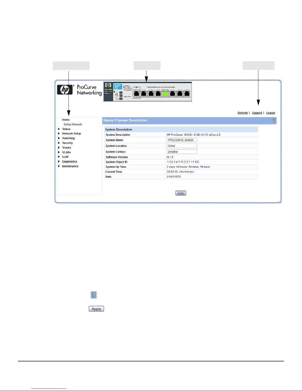
Interface Layout and Features
Navigation Pane
Web Applet
Common Links
Figure 1-2 shows the initial view.
Figure 1-2. Interface Layout and Features
Getting Started With the Web Interface
Getting Started
Click on any topic in the navigation page to display related configuration options.
The System Description page displays when you first log on and when you click Home or Status > System
Description in the navigation pane. See “System Description” on page 2-1 for more information.
You can click the Setup Network link beneath Home to display the Get Connected page, which you use
to set up a management connection to the switch. You can also click Network Setup > Get Connected to
display this page. See “Get Connected” on page 3-1 for more information.
The Web Applet displays summary information for the switch LEDs and port status in a graphical
format. For information on the Web Applet, see “Web Applet” on page 1-4.
Common Page Elements
■ Click on each page to display a help panel that explains the fields and configuration
options on the page.
■ Click to send the updated configuration to the switch. Configuration changes take
effect immediately, but some changes are not retained across a power cycle unless the changes
are saved to the system configuration file.
1-3
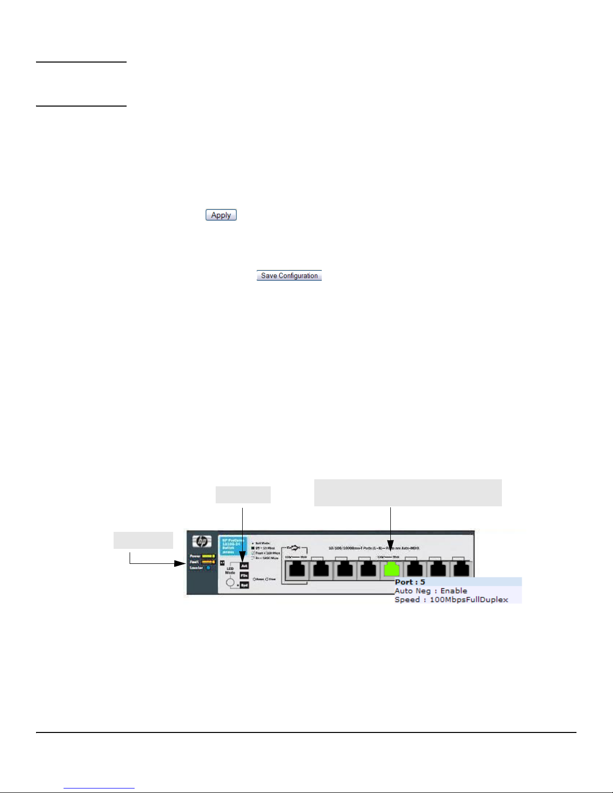
Getting Started
LED Mode
System LEDs
Port Configuration and Summary
(Point, left-click, or right-click on any port for options)
Getting Started With the Web Interface
CAUTION Configuration changes take effect immediately, but some changes are not retained across a
power cycle (or reboot) unless the changes are saved to the system configuration file. See
“Saving Changes” below.
■ Click Refresh to refresh the page with the latest information from the switch.
■ Click Support to access the HP ProCurve Web site (Internet access required).
■ Click Logout to end the current management session.
Saving Changes
When you click , changes are saved only for the current boot session. The changes will not be
retained after a reboot. To ensure changes to the system configuration file are saved so that they are
retained after a reboot:
1. Click Maintenance > Save Configuration in the Navigation pane.
2. On the Save page, click .
User-Defined Fields
User-defined fields can contain 1–31 characters, unless otherwise noted on the configuration Web page. All characters may
be used except for the following (unless specifically noted for that feature):
\<*|
/>|?
Web Applet
The Web Applet, as shown in Figure 1-3, displays at the top of the every page. It is a graphic
representation of the switch and provides information regarding the status parameters of individual
ports. The Web Applet enables easy system configuration and Web-based navigation.
Figure 1-3. Web Applet
■ Port Configuration and Summary — You can point to any port to display the following
information about the port:
• Auto Negotiation Status
•Speed
Left-click a port to display its Port Configuration page, or right-click and select from the menu to
display its Port Configuration Page or the Port Summary page for all ports.
1-4

Getting Started With the Web Interface
■ System LEDs— You can point to the System LEDs area to view information about the switch
Getting Started
LEDs.
Note The System LED area provides general, static information about the LEDs only. The display does not
change to reflect the current state of the LEDs.
Switch LEDs include the following:
• Power (Green)
– On— The system is being powered by AC/DC power or Power-over-Ethernet (PoE).
– Blinking — Power from the PoE port is lost or insufficient. The LED continues to blink
until PoE is restored or the system is reset.
– Off—The system is powered by the external power adapter.
Note 8-port HP ProCurve 1810G switches may be PoE Powered Devices (PD) through port 1 only. (24-port
ProCurve 1810G switches do not support PoE). The 8-port switches provide an additional PD LED,
which turns On if it is receiving PoE power through port 1.
• Fault (Orange)
– Blinking—A fault has occurred, other than during self-test.
– On— Failure during self-test.
– Off—The switch is operating properly.
• Locator — When on, the switch is in Locate Mode so that it can be physically located. This
mode can be enabled using the Web interface. See “Locator” on page 9-6.
■ LED Mode—Each port has two LEDs. The function of the right LED (called the Mode LED)
changes depending on the LED mode selected for the switch. Use the LED Mode button on
the switch to select a mode (Act, FDx, Spd).
You can move your cursor over the LED Mode area to view a description of the LED modes.
Note The LED modes area provides general, static information about the LEDs. The display does not change
to reflect the current state of the LEDs. The physical LED Mode behavior is described below.
On the switch, the active LED mode is indicated by three LEDs:
■ Act—Activity. When Act mode is selected, the Mode LED for each port will blink upon port
activity.
■ FDx—Full Duplex. When FDx mode is selected, the Mode LED for each active port will
illuminate only when the port is operating in full-duplex mode.
■ Spd—Speed. When Spd mode is selected, the Mode LED for each active port will illuminate
when the port is operating at 100 Mbps (blinking) or 1000 Mbps (solid on), or will be off when
the port is operating at 10 Mbps.
If the LED Mode button is not pressed for 10 minutes, the LED mode automatically returns to Activity
mode.
If Green Mode is enabled (see “Green Features” on page 4-5), which turns off the port LEDs, pressing
the LED Mode button temporarily restores the LED Mode feature.
1-5

Getting Started
Getting Started With the Web Interface
Note The left-port LED is not depicted in the Web Applet. It indicates link status, as follows:
■ On—The port is enabled and receiving a link indication or other signal from the connected
device.
■ Blinking—The port has experienced a self-test fault.
■ Off—The port has no active network cable connected, is not receiving link signal, or is
disabled.
1-6

Status Pages
You can use the Status pages to view system information and statistics.
System Description
The System Description page displays when you first log on and when you click Home or Status > System
Description in the navigation pane. It displays basic information such as the software version and system
up time. In addition, the system name, location, and contact can be configured on this page.
Figure 2-1. System Description Page
2
■ Click Apply to save any changes for the current boot session; the changes take effect
immediately. Use the Maintenance > Save Configuration page to have the settings remain in effect
after a reboot.
2-1
Status Pages
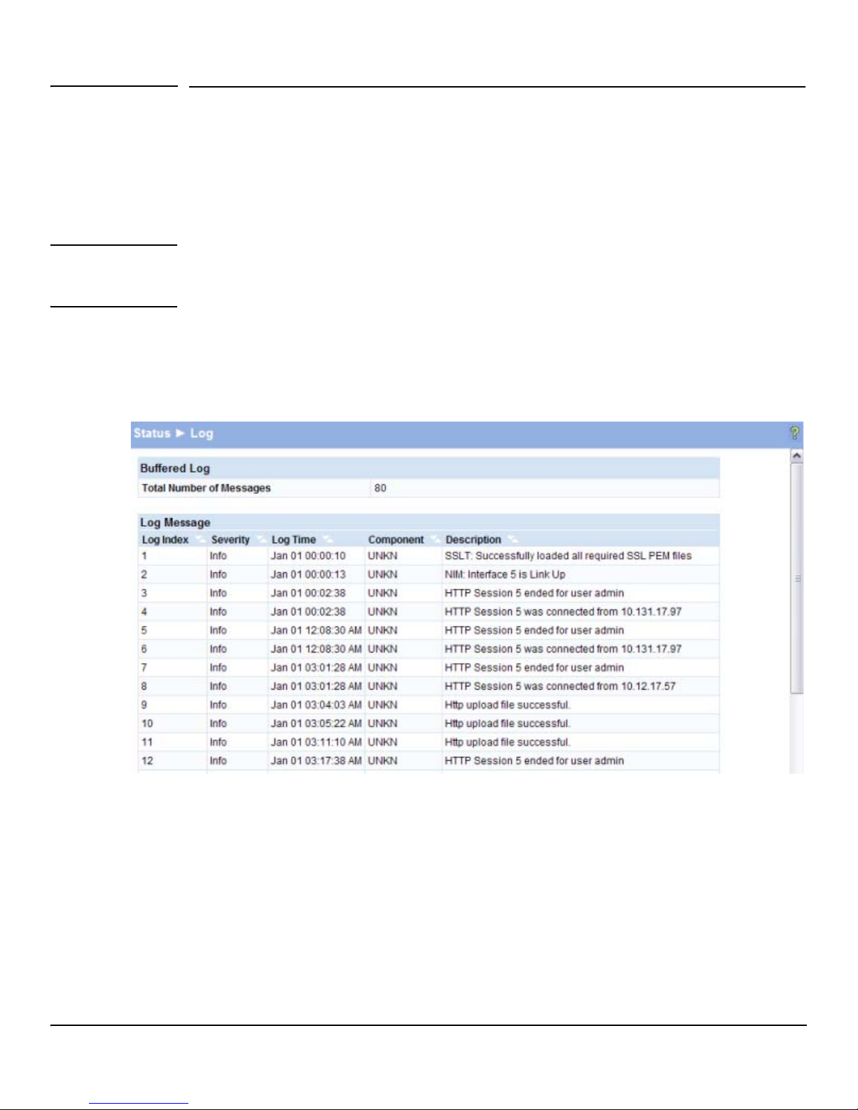
Log
Log
The Log table displays logged system messages, such as configuration failures and user sessions. The
log page displays the 100 most recent log entries. The newest log entry, by default, is displayed at the
bottom of the list.
Note If more than 100 logs accumulate, their Log Index numbers continue to increment beyond 100 and the
oldest entries are deleted (for example, if 200 log entries were generated since the system was last
restarted or the log file was cleared, then the log file would display entries 101–200).
To display this page, click Status > Log in the navigation pane.
Figure 2-2. Log Page
■ Click the arrows next to the column headings to sort the list by the column, in ascending or
descending order.
■ Click Clear to delete all log messages.
■ Click the Refresh link above the page to re-display the page with new logs.
For information on configuring log settings, see “Log Configuration” on page 9-2.
2-2
Status Pages
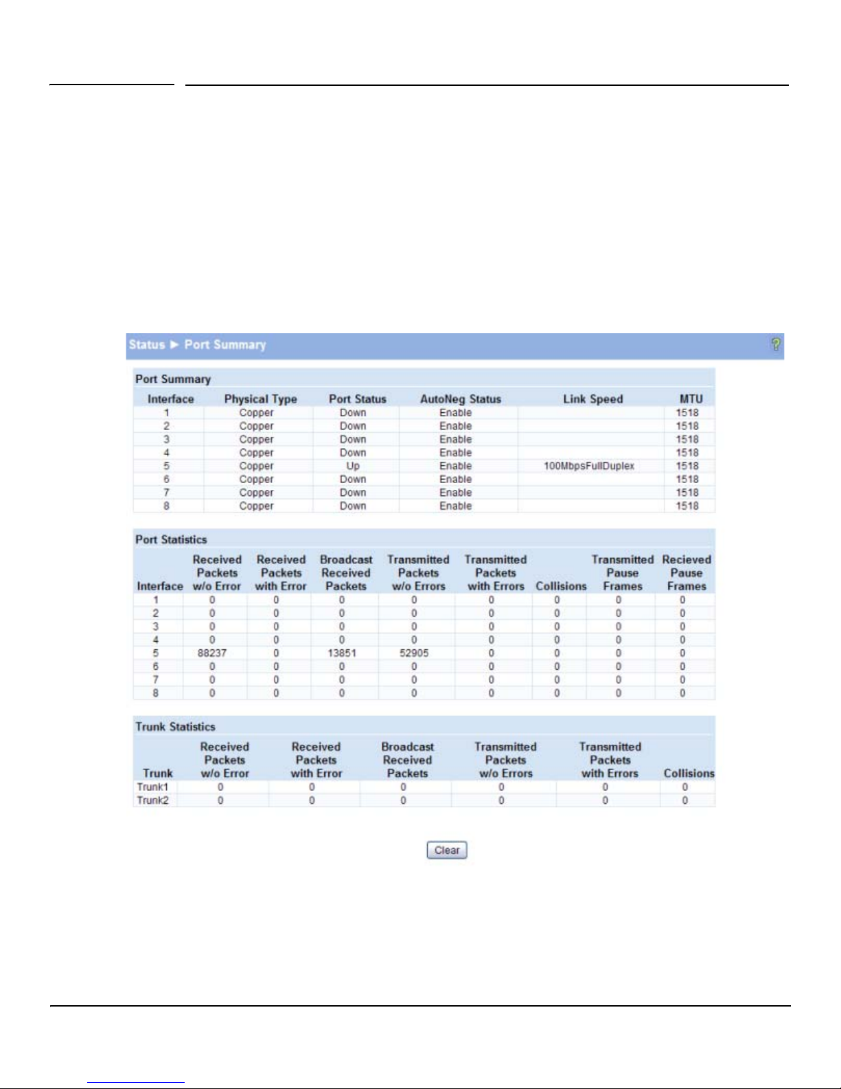
Port Summary
Port Summary
The Port Summary page displays a port summary at the top of the page and provides configuration and
status information for each port. Scroll down the page to view the Port Statistics table, which provides
per-port statistics on packets transmitted and received.
To display this page, click Status > Port Summary in the navigation pane.
A configuration summary and status of all physical and logical ports are displayed in Figure 2-3.
Figure 2-3. Port Summary Page
2-3

Status Pages
Port Summary
Table 2-1. Port Summary Fields
Field Description
Port Summary
Interface Displays list of physical and logical interfaces supported or configured on a particular
platform.
Physical Type Displays whether the port is operating in copper mode or fiber mode.
Port Status The physical status (Up or Down) of the port.
AutoNeg Status Displays whether Auto negotiation is enabled or disabled on the port.
Link Speed The physical speed at which the port is operating.
MTU The Maximum Transmission Unit (MTU), also referred to as Max Frame size acceptable
on the specified port.
Port Statistics and Trunk Statistics
Note: The following statistics are collected for both individual port and for trunks.
Interface The list of physical and logical interfaces supported on that platform.
Received Packets w/o Error The packet count received on the port with out any packet errors.
Received Packets with Error The packet count received on the port with errors.
Broadcast Received
The packet count for Broadcast packets received on the port.
Packets
Transmitted Packets w/o
The packets transmitted out of that port with out any packet errors.
Errors
Transmitted Packets with
The number of packets transmitted out of the port with packet errors.
Errors
Collisions The count of collided packets.
Transmitted Pause Frames (For ports only) The number of Ethernet pause frames transmitted.
Received Pause Frames (For ports only) The number of Ethernet pause frames received.
■ Click Clear to reset all statistics to their initial values.
■ Click the Refresh link above the page to re-display the page with the latest port information.
For instructions on configuring port settings, see “Port Configuration” on page 4-1.
2-4
Status Pages
LLDP Statistics
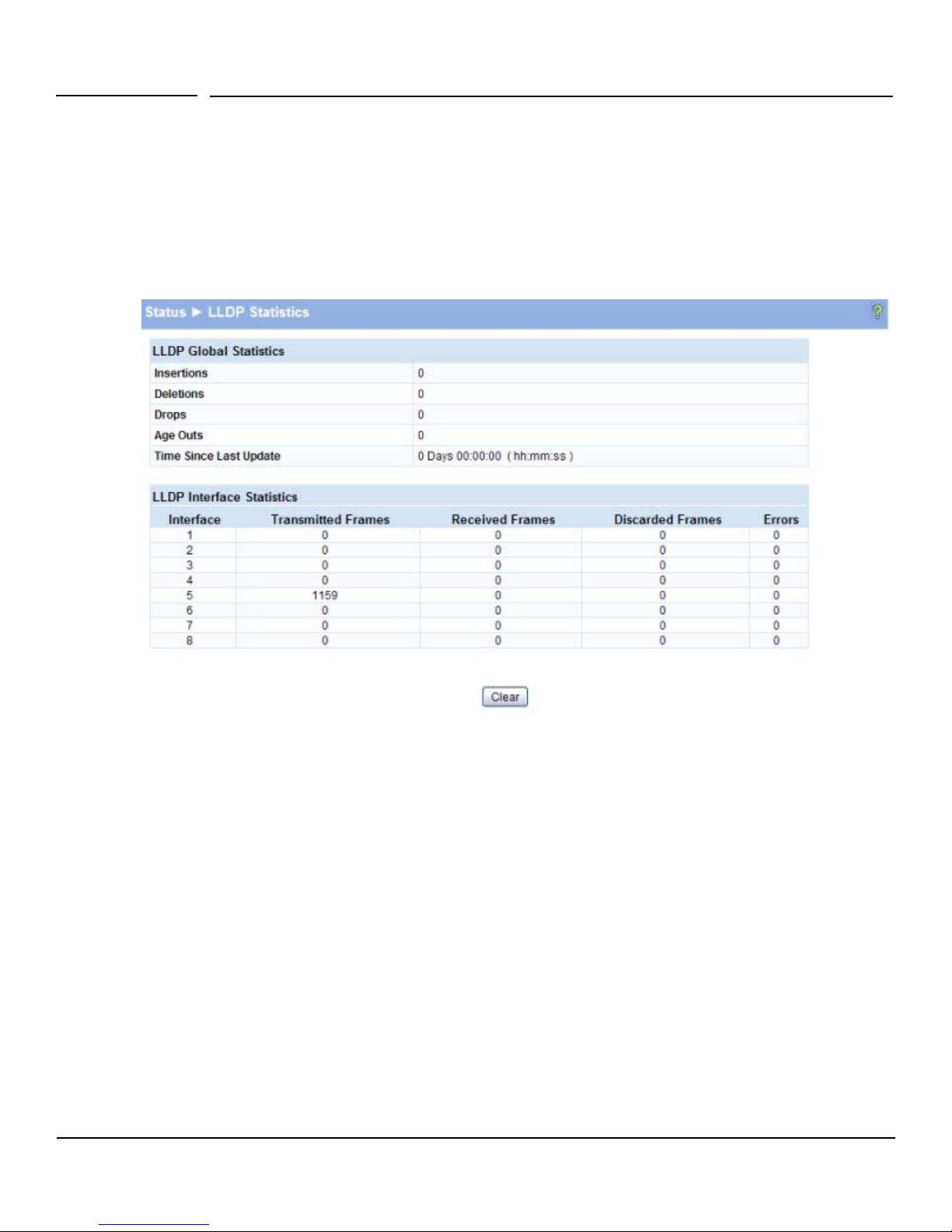
LLDP Statistics
The Link Layer Discovery Protocol (LLDP) Statistics page displays summary and per-port information
for LLDP frames transmitted and received on the switch. To display this page, click Status > LLDP
Statistics in the navigation pane.
Figure 2-4. LLDP Statistics Page
2-5

Status Pages
LLDP Statistics
Table 2-2. LLDP Statistics Page Fields
Field Description
LLDP Global Statistics
Insertions The number of times the complete set of information advertised by a particular MAC
Service Access Point (MSAP) has been inserted into tables associated with the remote
systems.
Deletions The number of times the complete set of information advertised by a particular MSAP has
been deleted from tables associated with the remote systems.
Drops The number of times the complete set of information advertised by a particular MSAP
could not be entered into tables associated with the remote systems because of
insufficient resources.
Age Outs The number of times the complete set of information advertised by a particular MAC
Service Access Point (MSAP) has been deleted from tables associated with the remote
systems because the information timeliness interval has expired.
Time Since Last Update Time when an entry was created, modified, or deleted in the tables associated with the
remote system.
LLDP Interface Statistics
Interface Interface or port number.
Transmitted Frames Number of LLDP frames transmitted on the corresponding port.
Received Frames Number of valid LLDP frames received by this LLDP agent on the corresponding port, while
the LLDP agent is enabled.
Discarded Frames Number of LLDP frames discarded for any reason by the LLDP agent on the
corresponding port.
Errors Number of invalid LLDP frames received by the LLDP agent on the
corresponding port, while the LLDP agent is enabled.
■ Click Clear to reset all statistics to their initial values.
■ Click the Refresh link above the page to re-display the page with current data from the switch.
2-6
For instructions on configuring LLDP, see “LLDP Configuration” on page 8-1.
Status Pages
Trunk
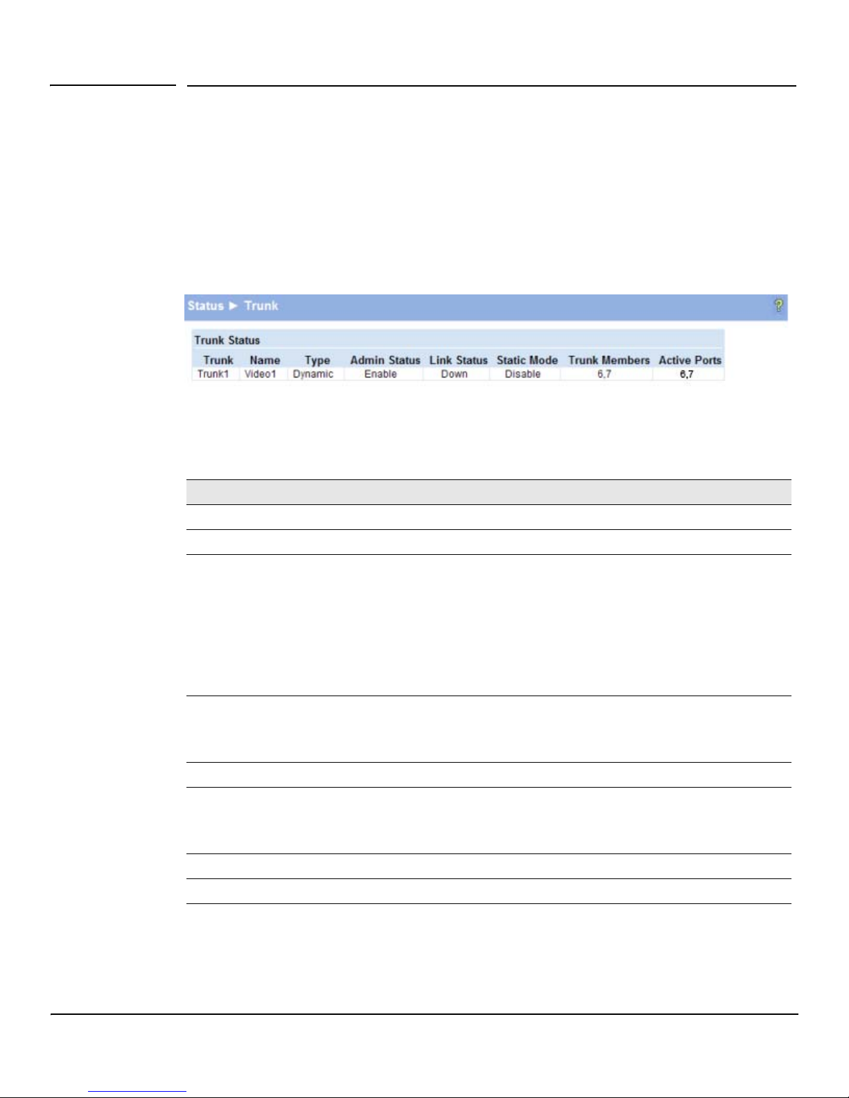
Trunk
The Trunk Status page displays the configuration summary and status of each trunk. To display this
page, click Status > Trunk in the navigation pane.
Figure 2-5 displays the configuration summary and status of a trunk named Trunk1. This trunk is
configured in dynamic mode and has 3 and 5 interfaces as its active members.
Figure 2-5. Trunk Status Page
Table 2-3. Trunk Port Configuration Fields
Field Description
Tru nk An ID assigned to the trunk by the system when the trunk is created.
Name A user-created name for the trunk.
Ty pe • Indicates whether the trunk is Static or Dynamic.
• Dynamic trunks use the Link Aggregation Control Protocol (LACP, IEEE standard 802.3ad). An
LACP-enabled port automatically detects the presence of other aggregation-capable network
devices in the system and exchanges Link Aggregation Control Protocol Data Units (LACPDUs)
with links in the trunk. The PDUs contain information about each link and enable the trunk to
maintain them.
• Static trunks are assigned to a bundle by the administrator. Members do not exchange
LACPDUs. A static trunk does not require a partner system to be able to aggregate its member
ports.
Admin Status Displays whether the trunk has been enabled or disabled administratively. When disabled, no
traffic will flow. The messages that members of the trunk exchange in order to manage the trunk
(LACPDUs) will be dropped, but the links that form the Trunk will not be released. The default is
Enable.
Link Status Displays whether the link is up or down.
Static Mode Displays whether Static mode has been enabled on the trunk. When static mode is enabled, the
trunk does not transmit or process received LACPDUs. The member ports do not transmit LACPDUs
and all the LACPDUs it may receive are dropped. A static trunk does not require a partner system
to be able to aggregate its member ports.
Trunk Members List of members ports in the trunk.
Active Ports List all active member ports in the trunk.
For information on configuring trunks, see “Trunk Configuration” on page 6-1.
2-7
Status Pages
MAC Table
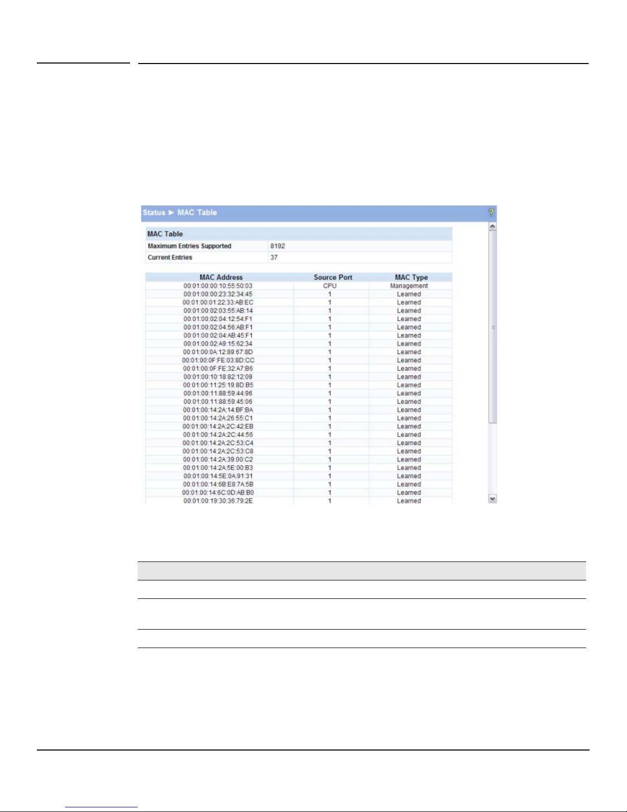
MAC Table
The MAC Table displays the MAC addresses associated with incoming packets on each port. Entries
are kept until they are aged-out based on the MAC Table Aging Interval, which cannot be configured
and set to 300 seconds by default.
To display the MAC Table, click Status > MAC Table in the navigation pane.
Figure 2-6. MAC Table Page
Table 2-4. MAC Table Fields
Field Description
MAC Address The list of MAC addresses learned on a particular interface.
Source Port The source interface on which the particular MAC address has been learned.
MAC Type Shows whether the MAC address is dynamically learned or whether this is a management address.
■ Click the Refresh link above the page to re-display the page with current data from the switch.
2-8
CPU is a special source port used for internal management on the switch.
 Loading...