

HP ProCurve 1410-24G Quick Setup Manual
HP ProCurve 1410-24G Switch Quick Setup Guide
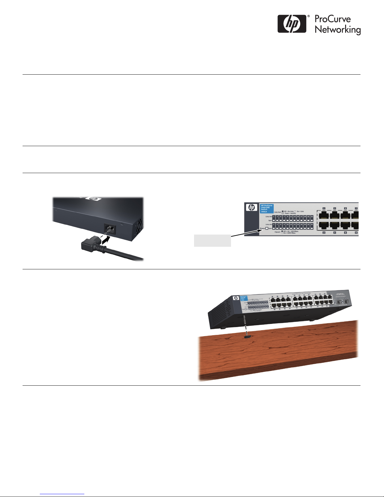
Power LED = On
© Copyright 2010 Hewlett-Packard Development Company, L.P.
The information contained herein is subject to change without
notice.
Printed in China
February 2010
5998-0335
*5998-0335*
For more detailed information to set up your switch, view or download the Installation and Getting Started Guide for your
switch at www.hp.com/go/procurve/manuals.
1. Unpack and check included parts. ■ Documentation kit
•Read Me First
• Quick Setup Guide
• Safety and Regulatory information
• Software License Agreement and Hardware Warranty
formation
in
■ Switch
■ Accessory kit (installation hardware)
■ AC power cord
2. Prepare for installation. To avoid personal injury or product damage, review the “Safety Precautions” on
page 3.
3. Connect power and verify that the switch power LED turns on. The switch does not contain a power switch. It is
turned on by connecting power through the AC power cord.
4. Install the Switch Hardware. Turn off the switch before installing the switch hardware.
Table or Desktop: At
(included in the accessory kit) to the bottom corners of
the switch.
tach the four self-adhesive pads
1

4. Install the Switch Hardware (Continued)
M-4 tap
screws
Ventilation
Wall (or Under-Table):
For wall or under-table mounting,
use a #1 Phillips (cross-head) screwdriver and the 20-mm M4
tap screws (included). For screw positions, see the mounting
template on page 4. (Under-Table: After installation, a third
screw may be used to prevent switch movement.)
For wall-mounting, the network ports must be facing up (see
gure). Do not mount the switch with ports facing down, or
fi
ventilation ducts on the side of the switch facing up or down.
(See “Safety Precautions” on page 3.)
Rack Mounting: A speci
al rack-mounting kit is included. Use a #1 Phillips (cross-head) screwdriver to attach the special
brackets to the switch using the eight 8-mm M4 screws. Then use the four number 12-24 screws to secure the brackets to the
rack.
5. (Optional) Lock the Switch. Use a Kensington lock or
similar device (not included) to physically secure the switch.
6. Power On the Switch and Connect Network Cables.
For transceiver connections, use o
mini-GBIC/SFP transceivers.
After installing a transceiver, allow it to initialize (wait a few
second
s) before removing it.
nly supported HP ProCurve
2
 Loading...