

Page 1

HP Utility Meter User's Guide for version 8.13
Fifth Edition
HP Part Number: T2805-90008
Published: August 2008
Page 2

© Copyright 2008 Hewlett-Packard Development Company, L.P.
Legal Notices
Confidential computer software. Valid license from HP required for possession, use or copying. Consistent with FAR 12.211 and 12.212, Commercial
Computer Software, Computer Software Documentation, and Technical Data for Commercial Items are licensed to the U.S. Government under
vendor's standard commercial license.
The information contained herein is subject to change without notice. The only warranties for HP products and services are set forth in the express
warranty statements accompanying such products and services. Nothing herein should be construed as constituting an additional warranty. HP shall
not be liable for technical or editorial errors or omissions contained herein.
Acknowledgments
Intel and Itanium are trademarks or registered trademarks of Intel Corporation or its subsidiaries in the United States and other countries.
Microsoft and Windows are U.S. registered trademarks of Microsoft Corporation.
Page 3

Table of Contents
About This Document...................................................................................11
1 Intended Audience.............................................................................................................................11
2 Publishing History..............................................................................................................................11
3 Document Organization......................................................................................................................11
4 Common Utility Meter Tasks................................................................................................................12
5 Locating This Guide............................................................................................................................13
6 Typographic Conventions....................................................................................................................13
7 Related Documents.............................................................................................................................13
8 HP Encourages Your Comments...........................................................................................................13
1 Introduction.............................................................................................15
1.1 Overview........................................................................................................................................15
1.2 What is New for Version 8.13...........................................................................................................17
1.3 Reminder of What was New in Version 8.12.03...................................................................................17
1.4 Recommended Hardware.................................................................................................................17
1.4.1 Swapping Utility Meter Hardware..............................................................................................17
1.4.2 Disk Space Requirements..........................................................................................................17
1.4.3 Supported URS Platforms..........................................................................................................18
1.4.4 Supported PPU Platforms..........................................................................................................19
1.5 Software.........................................................................................................................................19
1.5.1 Utility Meter Software Dependencies..........................................................................................20
1.5.2 Utility Meter Software Back Up..................................................................................................20
1.5.3 Utility Meter Directory Structure.................................................................................................20
1.6 Installation and Support Services.......................................................................................................21
1.7 Data Sent to HP...............................................................................................................................21
1.8 Missing Usage Reports.....................................................................................................................21
1.9 Data Transport Methods...................................................................................................................22
1.10 Utility Pricing Solutions Web Portal...................................................................................................23
1.11 Ordering.......................................................................................................................................23
2 Installing and Configuring the Utility Meter Software.....................................25
2.1 Overview........................................................................................................................................25
2.2 Skills Required................................................................................................................................26
2.3 Before Going to the Customer Site.....................................................................................................26
2.4 Configuring the HP-UX System Parameters...........................................................................................27
2.5 Installing the HP Systems Insight Manager Software.............................................................................27
2.6 Installing the Utility Meter Software....................................................................................................28
2.6.1 Installing the Utility Meter Software from the HP Software Depot....................................................28
2.6.2 Installing the Utility Meter Software from the Software Media (CD or DVD).....................................29
2.6.3 Completing the Utility Meter Software Installation........................................................................30
2.7 Configuring the Utility Meter Parameters.............................................................................................30
2.8 URS XP Only – Installing the XP CV AE CLI Software............................................................................34
2.8.1 Avoiding CLI Conflicts..............................................................................................................35
2.9 email Masquerading.......................................................................................................................35
2.9.1 Automated email Masquerading................................................................................................36
2.9.2 Manual email Masquerading....................................................................................................36
2.9.3 Verifying email Masquerading..................................................................................................37
2.10 Configuring PPU Partitions and URS Devices......................................................................................39
2.11 Verifying the Utility Meter Operation.................................................................................................39
2.12 Completing the Utility Meter Installation and Configuration..................................................................39
2.13 Upgrading the Utility Meter Software to Version 8.13..........................................................................39
Table of Contents 3
Page 4

3 Performing Utility Meter Tasks....................................................................41
3.1 Starting the Utility Meter GUI............................................................................................................42
3.2 The Main Window..........................................................................................................................44
3.3 Utility Meter Help Information...........................................................................................................47
3.4 Utility Meter Configure Tasks............................................................................................................48
3.4.1 Network Configuration.............................................................................................................49
3.4.1.1 Utility Meter Software Parameters.......................................................................................50
3.4.1.2 To Change the Utility Meter Software Parameters.................................................................51
3.4.2 Copy the Meter's Configuration................................................................................................53
3.4.3 Load the Meter’s Configuration.................................................................................................53
3.4.4 Storage Devices Namespace Configuration................................................................................53
3.5 Utility Meter Devices Tasks................................................................................................................55
3.5.1 Configure a Device (Add Device)...............................................................................................56
3.5.1.1 Add an EVA Device..........................................................................................................57
3.5.1.2 Add an XP Device............................................................................................................59
3.5.1.3 Add a PPU WBEM Partition/Server....................................................................................61
3.5.2 Modify Device........................................................................................................................63
3.5.2.1 Change a non-URS Disk Array to URS................................................................................63
3.5.2.2 Change PPU WBEM Partition/Server Configuration Parameters.............................................65
3.5.3 View Device...........................................................................................................................65
3.5.4 Remove Device.......................................................................................................................66
3.5.5 Discover Physical Devices.........................................................................................................67
3.6 Utility Meter Diagnose Tasks.............................................................................................................68
3.6.1 Meter Connection Status...........................................................................................................69
3.6.2 Device Connection..................................................................................................................70
3.6.2.1 Verify Device Connection..................................................................................................70
3.6.2.2 Device Connection - PPU WBEM Partition/Server................................................................71
3.7 Transfer Data through CD Task..........................................................................................................73
4 Verifying Utility Meter Operation................................................................77
4.1 Verifying the Utility Meter Hardware is Operational.............................................................................77
4.2 Verifying the Utility Meter Software is Operational..............................................................................77
4.3 Verifying the Correct Version of HP SIM is Installed..............................................................................78
4.4 Verifying the CIM Server Software Is Operational................................................................................78
4.5 Verifying Connectivity from the Utility Meter to HP...............................................................................80
4.5.1 Data Transfer by HTTPS............................................................................................................80
4.5.2 Data Transfer by email.............................................................................................................81
4.6 Verifying the Data Acquisition Server is Running..................................................................................82
4.7 Verifying the Utility Meter Data Transport Method................................................................................82
4.8 Verifying a PPU Partition...................................................................................................................82
4.8.1 Verify PPU WBEM Partition/Server Configuration.........................................................................82
4.8.2 Verify PPU Agent Configuration.................................................................................................82
4.8.3 Test Connection from PPU Agent to Utility Meter..........................................................................83
4.8.4 Test Connection from PPU Partition to UPS Web Portal..................................................................83
4.9 Verifying a Storage Device...............................................................................................................86
4.9.1 Verifying a Device is Configured in the Utility Meter.....................................................................86
4.9.2 Verifying a Device is Connected to the Utility Meter.....................................................................87
4.9.3 Verifying the Connection from the Utility Meter to HP...................................................................87
4.9.4 XP Only – Verifying the Correct Version of XP CV AE CLI is Installed..............................................88
5 Troubleshooting the Utility Meter.................................................................89
5.1 Troubleshooting Overview.................................................................................................................89
5.2 Utility Meter Software......................................................................................................................90
5.3 Troubleshooting a Device.................................................................................................................91
5.3.1 Troubleshooting a Storage Device..............................................................................................91
5.3.2 Troubleshooting a WBEM Device..............................................................................................92
5.4 Fixing a Disconnected Device (with Red Box)......................................................................................93
4 Table of Contents
Page 5

A Site Preparation Form for Pay Per Use..........................................................95
A.1 Networking details on the PPU WBEM Partition/Server........................................................................96
B Site Preparation Form for Utility Ready Storage.............................................97
B.1 Networking Details for the Command View XP AE Server......................................................................98
B.2 Networking Details for the Command View EVA Server........................................................................99
C Data Fields Sent from the Utility Meter to HP..............................................101
Glossary..................................................................................................103
Index.......................................................................................................105
Table of Contents 5
Page 6

6
Page 7

List of Figures
1-1 Flow of Metered Usage Data............................................................................................................16
2-1 Utility Meter GUI Main Window.......................................................................................................32
2-2 Network Configuration Dialog Box....................................................................................................33
3-1 Utility Meter GUI Main Window.......................................................................................................43
3-2 Utility Meter GUI Main Window Panes..............................................................................................45
3-3 Utility Meter GUI Managed Devices Tree............................................................................................46
3-4 Closing the Utility Meter GUI............................................................................................................47
3-5 GettingStarted Tab..........................................................................................................................48
3-6 Configure Tab................................................................................................................................49
3-7 Network Configuration Dialog Box....................................................................................................52
3-8 Save the Meter's Configuration Message...........................................................................................53
3-9 Namespace Configuration Dialog Box...............................................................................................54
3-10 Devices Tab.................................................................................................................................56
3-11 Add Device Dialog Box for EVA Device............................................................................................58
3-12 Add Device Dialog Box for XP Device..............................................................................................60
3-13 Add Device Dialog Box for PPU WBEM Partition/Server....................................................................62
3-14 Modify EVA Device Dialog Box......................................................................................................64
3-15 Modify PPU WBEM Partition/Server Dialog Box...............................................................................65
3-16 View Device Window....................................................................................................................66
3-17 View Device Error Window............................................................................................................66
3-18 Remove Device Window................................................................................................................67
3-19 Discovery of Physical Devices Message............................................................................................68
3-20 Diagnose Tab...............................................................................................................................69
3-21 Meter Connection Status Message...................................................................................................70
3-22 Diagnose Device Window.............................................................................................................70
3-23 Diagnose Device Results Window...................................................................................................71
3-24 Diagnose PPU WBEM Partition/Server Window................................................................................72
3-25 Diagnose PPU WBEM Partition/Server Results Window......................................................................72
3-26 Diagnose PPU WBEM Partition/Server Send Test Report Window........................................................73
3-27 Network Configuration Dialog Box — Data CD................................................................................74
3-28 Utility Meter GUI with SaveDataToCD Tab........................................................................................75
3-29 SaveDataToCD Tab.......................................................................................................................76
4-1 UPS Portal Welcome Page................................................................................................................84
4-2 Meter Connectivity Input Page...........................................................................................................85
4-3 Meter Connectivity Verification Page..................................................................................................85
4-4 Meter Connectivity Failure Page........................................................................................................86
4-5 Utility Meter GUI Managed Devices..................................................................................................87
5-1 Disconnected Device (with red box)...................................................................................................94
7
Page 8

8
Page 9

List of Tables
1 Common Utility Meter Tasks..................................................................................................................12
1-1 Recommended Minimum Hardware...................................................................................................17
1-2 Disk Space Requirements for 1,000 PPU Partitions...............................................................................18
1-3 Disk Space Requirements for 1,000 URS Devices.................................................................................18
3-1 Utility Meter GUI Tasks....................................................................................................................41
3-2 Starting the Utility Meter GUI with Specific Tabs..................................................................................44
A-1 PPU Site Preparation Form................................................................................................................95
A-2 Networking Details for the PPU WBEM Partition/Server.......................................................................96
B-1 PPU Networking Details Form...........................................................................................................97
B-2 Networking Details for the Command View XP AE Server.....................................................................98
B-3 Networking Details for the Command View EVA Server........................................................................99
C-1 PPU Partition Usage Data Fields Sent from the Utility Meter to HP.........................................................101
C-2 XP and EVA Usage Data Fields Sent from the Utility Meter to HP.........................................................102
9
Page 10

10
Page 11

About This Document
This document provides instructions for installing, configuring, and verifying the operation of version 8.13
of the HP Utility Meter software (HP products T2805AA and T5462A) on supported HP servers running either
HP-UX 11i v2, or HP-UX 11i v3.
1 Intended Audience
This guide is intended to primarily be used by HP personnel who initially install and configure the Utility
Meter hardware and software for Pay per use (PPU) and Utility Ready Storage (URS) customers.
This guide is also intended to be used by PPU and URS customers who:
• Reinstall the HP Utility Meter software and make configuration changes.
• Use the HP Utility Meter software graphical user interface (GUI) to change Utility Meter parameters.
• Verify operation of the Utility Meter.
• Troubleshoot the Utility Meter. (For example, if HP stops receiving usage data from the Utility Meter
and corrective action is necessary.)
The audience of this guide is expected to have the following knowledge:
• HP-UX operating system concepts, commands, and configuration
• PPU Agent software commands and configuration (for PPU installations using the PPU Agent software
to send reports to the meter)
• WBEM Services and providers installation on HP-UX and Linux (for PPU WBEM installations).
• Disk array configuration and Command View product experience (for URS installations)
• sendmail experience and understanding of detailed information in the appropriate (11i v2, or 11i
v3)
HP-UX Mailing Services Administrator's Guide
2 Publishing History
This is the fifth edition of the
Publication Date: August 2008
This guide supersedes the previous guides:
• The initial
and is located at: /opt/meter/share/doc/UtilityMeterUserGuide.pdf
• The
and is located at: /opt/meter/share/doc/UtilityMeterUserGuide.pdf
HP Utility Meter User's Guide for version 8.13
HP Utility Meter User's Guide for version 8.12.03
HP Utility Meter User's Guide for version 8.13
3 Document Organization
For initial installation and configuration of the Utility Meter hardware and software, the following chapters
should be read:
• Preface (this chapter)
• Chapter 2 (page 25)
• Chapter 4 (page 77)
For customers who reinstall or reconfigure the Utility Meter, the following chapters should be read:
• Preface (this chapter)
at: http://docs.hp.com.
(HP part number: T2805-90008).
which is included with the Utility Meter software
which is included with the Utility Meter software
• Chapter 1 (page 15)
• Chapter 2 (page 25)
• Chapter 4 (page 77)
The other chapters in this guide are provided for more specific information, such as Chapter 5 (page 89).
You can use the
Index
to find specific topics of interest, such as installing the Utility Meter software.
1 Intended Audience 11
Page 12

IMPORTANT: In some of the screenshots in this guide it has been necessary to either blur information or
input invalid information in order to ensure the security of certain HP IP addresses and system names. These
edits do not affect any Utility Meter procedures.
4 Common Utility Meter Tasks
Common Utility Meter Tasks lists the common tasks related to the Utility Meter and provides links to the
information in this guide.
Table 1 Common Utility Meter Tasks
SeeTo
software
Upgrade the Utility Meter software to 8.13
email address)
Chapter 2: “Installing and Configuring the Utility Meter Software”Get information about installing and configuring the Utility Meter
Configuring the HP-UX System ParametersConfigure the HP-UX system parameters for the Utility Meter
Section 2.13: “Upgrading the Utility Meter Software to Version
8.13”
Installing the Utility Meter SoftwareInstall the Utility Meter software
Configuring the Utility Meter ParametersConfigure the Utility Meter parameters
Starting the Utility Meter GUIStart the Utility Meter GUI
To Change the Utility Meter Software ParametersModify the Utility Meter parameters (such as Utility Meter contact
Copy the Meter’s ConfigurationCopy the Utility Meter's current configuration to a backup file
Storage Devices Namespace ConfigurationConfigure (add) a storage device namespace
Add DeviceAdd a device to the Utility Meter
Modify DeviceModify a device in the Utility Meter
View DeviceView information for a PPU WBEM Device
Remove DeviceRemove a device from the Utility Meter
Discover Physical DevicesDiscover the physical devices (disk arrays)
Transfer Data through CD TaskTransfer the usage data on a CD to HP
Meter Connection StatusEnsure the Utility Meter's data acquisition server is running
Get information about the Utility Meter Site Preparation Form
requirements
12 About This Document
Device ConnectionTest the connection between a device and the Utility Meter
Chapter 4: “Verifying Utility Meter Operation”Verify the Utility Meter's operation
Chapter 5: “Troubleshooting the Utility Meter”Troubleshoot the Utility Meter
Verifying a PPU PartitionVerify a PPU partition is communicating with the Utility Meter
Verifying a Storage DeviceVerify a storage device
Appendix A: “Site Preparation Form for Pay Per Use”
Appendix B: “Site Preparation Form for Utility Ready Storage”
Recommended HardwareGet information about the recommended Utility Meter system
Utility Meter GUI TasksGet information about the Utility Meter GUI tasks
Utility Pricing Solutions Web PortalGet information about the Utility Pricing Solutions Web portal
Locating This GuideObtain this guide
Related DocumentationFind documentation related to the Utility Meter
Appendix C: “Data Fields Sent from the Utility Meter to HP”Get information about what data is sent to HP by the Utility Meter
Missing Usage ReportsGet information about missing usage reports
Page 13

5 Locating This Guide
This guide is available from the following sources:
• The HP Technical Documentation Web site: http://docs.hp.com/en/netsys.html#Utility Pricing Solutions
• The
• After the Utility Meter software has been installed, a PDF of this guide is located at:
IMPORTANT: The guide included with the Utility Meter software is the initial version for this release. Check
the HP Technical Documentation Web site for the latest revisions of this guide.
HP-UX Instant Information
/opt/meter/share/doc/UtilityMeterUserGuide.pdf.
6 Typographic Conventions
find
(1) HP-UX manpage. In this example, “find” is the manpage name and “1” is the
manpage section.
Book Title
Linked Title
http://www.hp.com A Web site address that is a hyperlink to the site.
Command Command name or qualified command phrase.
user input Commands and other text that you type.
computer output Text displayed by the computer.
Enter The name of a keyboard key. Note that Return and Enter both refer to the same
term Defined use of an important word or phrase.
variable The name of an environment variable, for example PATH or errno.
value A value that you may replace in a command or function, or information in a display
<element> An element used in a markup language.
attrib= An attribute used in a markup language.
Title of a book or other document.
Title that is a hyperlink to a book or other document.
key. A sequence such as Ctrl+A indicates that you must hold down the key labeled
Ctrl while pressing the A key.
that represents several possible values.
media (CD or DVD)
7 Related Documents
The following HP documentation is related to the Utility Meter:
• HP Utility Computing Services: http://h20219.www2.hp.com/services/cache/96797-0-0-225-121.html
• Pay per use User's Guides: http://docs.hp.com/en/netsys.html#Utility Pricing Solutions
• HP Storage Array Systems documents: http://docs.hp.com/en/storage.html#Storage Array Systems
8 HP Encourages Your Comments
HP encourages your comments concerning this document. We are committed to providing documentation
that meets your needs. Send any errors found, suggestions for improvement, or compliments to:
feedback@fc.hp.com
Include the document title, manufacturing part number, and any comment, error found, or suggestion for
improvement you have concerning this document.
5 Locating This Guide 13
Page 14

14
Page 15

1 Introduction
1.1 Overview
The Utility Meter is a component in the setup of a Pay per use (PPU) or Utility Ready Storage (URS) solution.
PPU and URS are part of HP's Utility Pricing Solutions (UPS) program. In this program, customers are charged
according to usage of the PPU and URS computing resources (servers and storage) under a UPS contract.
For more information on this program, see the Metered Capacity link on the Utility Pricing Web page: http:/
/h71028.www7.hp.com/enterprise/cache/308072-0-0-0-121.html.
For version 8.13 of the HP Utility Meter software, the HP “Utility Meter” is a combination of both an HP
server running HP-UX and the HP Utility Meter software. For the list of compatible Utility Meter HP-UX servers,
see Recommended Hardware.
The Utility Meter is usually located at the customer site along with the customer’s UPS computing resources.
The Utility Meter only needs to connect to a UPS computing resource through the TCP/IP protocol. There is
no geographical limit as to where the UPS computing resources are located.
The main task of the Utility Meter is to receive usage information from UPS computing resources that are
under an HP UPS Utility contract (such as HP servers and HP storage devices) and send the usage data in
a secure way to HP. The Utility Meter tracks the usage of:
• Enterprise servers – A specific set of both HP Integrity servers and HP 9000 servers are supported in
the PPU Utility program. The supported PPU enterprise servers are partitionable and each PPU partition
must be configured to be metered by the Utility Meter. In version 8.13 there are now two ways to
monitor a server: via the PPU Agent software or (new to version 8.13) by adding a PPU WBEM
Partition/Server to the meter.
For PPU Agent devices, communication can be configured between the PPU partition and the Utility
Meter through the appropriate PPU Agent software command on each PPU partition. Refer to the
User's Guide
Agent software sends PPU usage data to the Utility Meter, then the Utility Meter sends the data securely
to HP.
For a PPU WBEM Partition/Server, communication can be configured by adding a PPU WBEM
Partition/Server to the Utility Meter via the Utility Meter GUI.
PPU
(see Related Documentation) for details of the PPU Agent software commands. The PPU
• Storage devices – Specific EVA and XP storage devices are supported in the Utility Ready Storage (URS)
program. Both the Command View server and its disk arrays, which are to be metered by the Utility
Meter, must be configured using the Utility Meter software's graphical user interface (GUI). Usage data
is obtained in the following ways:
• XP: Usage data is retrieved through the HP StorageWorks XP Command View Advanced Edition
Command Line Interface (CLI) software that is installed on the Utility Meter. The CLI software
communicates with the HP StorageWorks XP Command View Advanced Edition server that is on
a separate system.
• EVA: Usage data is retrieved through the HP Systems Insight Manager (HP SIM) database on the
Utility Meter. The HP SIM database receives its data from the HP StorageWorks Command View
EVA server through the SMI-S service that is on a separate system.
The Utility Meter software sends the URS usage data securely from the Utility Meter to HP.
NOTE: A single Utility Meter can meter up to 1,000 metered instances (server partitions plus storage
devices).
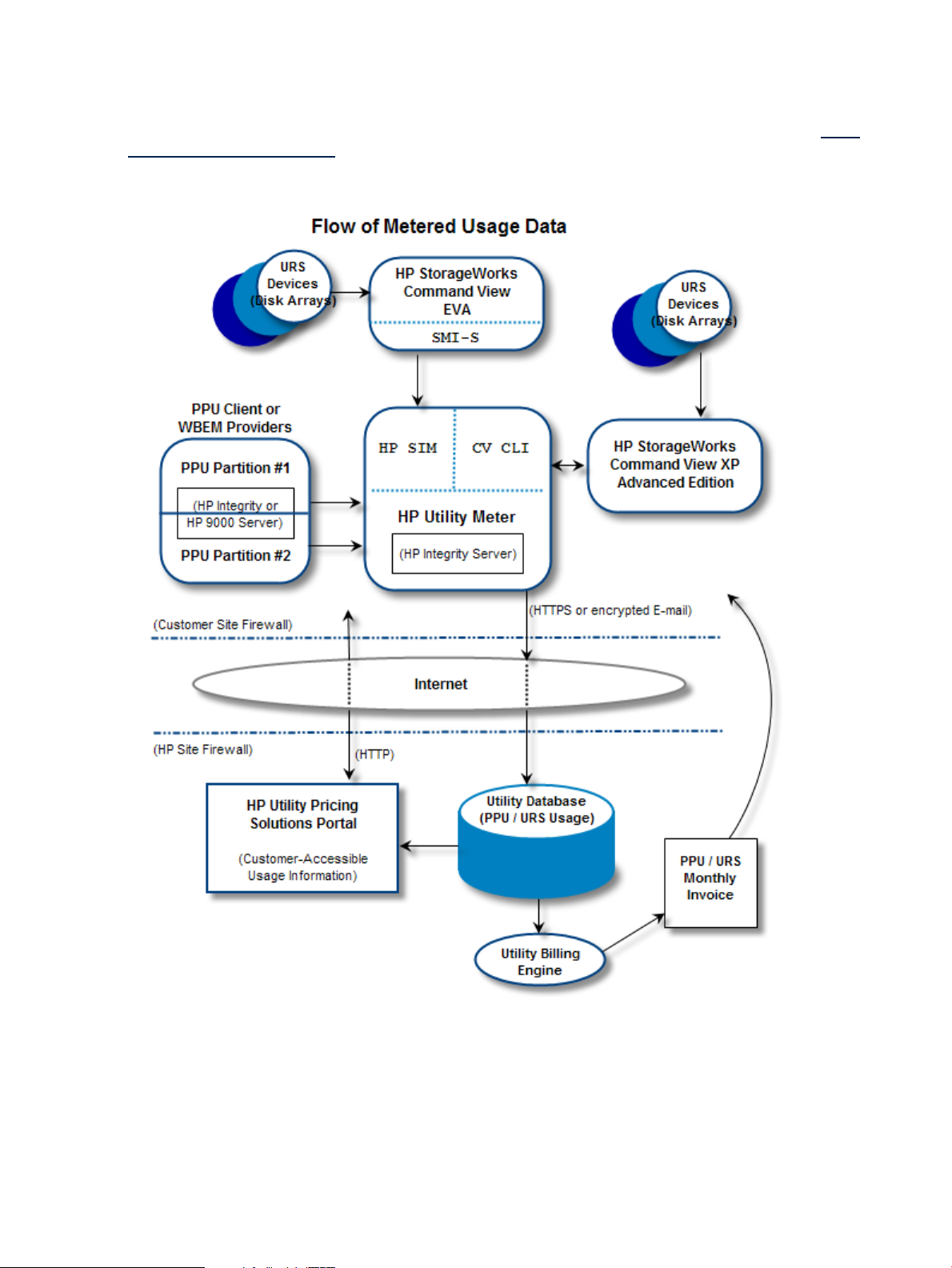
See Flow of Metered Usage Data for details of the usage-data flow from the UPS computing resources to
HP.
The Utility Meter sends PPU and URS usage data to HP securely over the Internet through HTTPS or email on
a daily basis. Data sent to HP is encrypted before transmitting.
The Utility billing engine processes usage data from the Utility database once per month and billing information
is sent to the customer.
1.1 Overview 15
Page 16
The monthly bill contains a fixed amount (for the hardware, software and services) and a variable amount.
The variable amount is based on the usage of the UPS computing resources (disk space and processor cores).
The PPU and URS usage data is stored in the Utility database at HP on a per-UPS-computing-resource basis.
Customers can monitor their usage information on the secure HP Utility Pricing Solutions Web Portal: http:/
/www.hp.com/go/payperuse
Figure 1-1 Flow of Metered Usage Data
The communication from the Utility Meter to the PPU Partition is secure WBEM (HTTPS on port 5989). This
port must be open from the Utility Meter to any PPU partition that needs to be metered. Consult the network
administrator if special firewall configuration is necessary.
No proxy server can be configured between the PPU partition(s) and the Utility Meter. There can be a proxy
server between the Utility Meter and the Internet for HTTPS traffic.
16 Introduction
Page 17

1.2 What is New for Version 8.13
Version 8.13 of the Utility Meter software is the fifth release of the Utility Meter 8.x software. Version 8.13
includes the following changes:
• Multi-Tiering billing support for XP storage whereby billing can be based on the different disk types in
the array. Previously all XP disks were charged the same amount.
• A change in how usage is reported for THP on an XP storage device. Now usage is reported for the
amount used whereas previously usage was reported for the amount set aside in THP pools.
• 8.13 will be the first release that supports XP20000 and EVA4400.
1.3 Reminder of What was New in Version 8.12.03
Version 8.12.03 of the Utility Meter software was the fourth release of the Utility Meter 8.x software. Version
8.12.03 included the following changes:
• An alternative method for metering HP-UX servers was made available. Previously, this could only be
accomplished by installing and configuring the PPU Agent software on each HP-UX partition. For Version
8.12.03 HP-UX partitions could be metered by installing the standard CIM/WBEM software, usually
done when the OS was installed.
• Metering of Linux partitions (SUSE and RHEL) was possible via the CIM/WBEM software installed on
the metered server.
• Version 8.12.03 was the first release that did not support HP-UX 11i v1 for the meter operating system,
however, the meter continues to measure servers using HP-UX 11i v1.
1.4 Recommended Hardware
CAUTION: The hardware used to run the Utility Meter 8.13 software must be used exclusively for the Utility
Meter software application. That is, no other software applications or services are allowed on the Utility
Meter hardware.
The Utility Meter 8.13 software runs on many HP Integrity servers and HP 9000 servers; however, HP
recommends the following minimum Utility Meter hardware:
Table 1-1 Recommended Minimum Hardware
rp3440
HP-UX 11i v3
rx2620 or rx3600
HP-UX 11i v3
1 To increase redundancy, the two disks are preferably placed in a RAID 1 configuration using a hardware RAID controller, such as
the Smart Array Controller 6402 (HP product number A9890A).
1.4.1 Swapping Utility Meter Hardware
If you want to change the current Utility Meter hardware from one HP-UX server to another, you need to
contact an HP services representative to perform this task.
1.4.2 Disk Space Requirements
2 GBHP-UX 11i v2, or
2 GBHP-UX 11i v2 or
NetworkingPeripheralStorageMemoryOperating SystemServer Model
1
1
1
1
One Ethernet portDVD RW2 x 72 GB in RAID
One Ethernet portDVD RW2 x 72 GB in RAID
Depending on whether Pay per use (PPU) servers or Utility Ready Storage (URS), or both, are metered by
the Utility Meter, the /opt and /var directories must have enough space allocated to accommodate the
Utility Meter's usage reports.
The Utility Meter's /opt directory is a fixed size and must have a minimum of 2.5 GB of disk space allocated.
1.2 What is New for Version 8.13 17
Page 18
The size of the Utility Meter's /var directory depends on how many PPU partitions or URS devices are being
metered (plus about 500 MB of overhead). Here are some /var directory disk space requirements for 1,000
metered instances:
• PPU Partitions — 48 usage reports are created on a daily basis. Each report is 8 KB in size. 91 days
of usage data is retained in /var. For 1,000 PPU partitions to be metered:
48 * 8,000 * 91 * 1,000 = 34,944,000,000 (~35.5 GB including 500 MB of overhead) would be
required for /var.
Table 1-2 Disk Space Requirements for 1,000 PPU Partitions
Disk Space in Giga BytesLogical ExtentsFile System
2.5 GB313/opt
35.5 GB4,400/var
• URS Devices — One usage report is created on a daily basis. Each report is 8 KB in size. 91 days of
usage data is retained in /var. For 1,000 URS devices to be metered:
1 * 8,000 * 91 * 1,000 = 728,000,000 ( ~1.25 GB including 500 MB of overhead) would be
required for /var.
Table 1-3 Disk Space Requirements for 1,000 URS Devices
Disk Space in Giga BytesLogical ExtentsFile System
2.5 GB313/opt
You can estimate the disk space needed for /var for a combination of PPU partitions and URS devices.
NOTE: When initially configuring the Utility Meter system, you can allocate any remaining disk space to
/var to ensure there is enough space for usage reports.
1.4.3 Supported URS Platforms
The following Utility Ready Storage (URS) platforms are supported:
• XP
XP10000•
• XP12000
• XP20000
• XP24000
IMPORTANT: URS XP installations must have version 6.0 (or later) of the HP StorageWorks XP
Command View Advanced Edition software installed on all XP Command View servers. Also, version
6.0 (or later) of the HP StorageWorks XP Command View Advanced Edition Command Line Interface
(CLI) software must be installed on the Utility Meter. The version of the CLI on the meter must be equal
to or lower than the version of the CV software installed on the XP Command View server.
1.25 GB157/var
• EVA
18 Introduction
EVA4000•
• EVA4100
• EVA4400
• EVA6000
• EVA6100
• EVA8000
• EVA8100
Page 19

IMPORTANT: URS EVA installations must have version 6.x (or later) of the HP StorageWorks Command
View EVA Advanced Edition software installed on all EVA Command View servers.
1.4.4 Supported PPU Platforms
Below is a list of currently supported PPU WBEM platforms:
• HP-UX
• Redhat Enterprise Linux, versions 4 U5 and 5 U1 (not yet GA)
• SUSE Linux Enterprise Server 10 SP1
For the list of currently supported PPU Agent platforms, refer to the specific
http://docs.hp.com/en/netsys.html#Utility Pricing Solutions
1.5 Software
Version 8.13 of the HP Utility Meter software is available as the following HP products:
• For Pay per use (PPU) installations: T2805AA
• For Utility Ready Storage (URS) installations: T5462A
That is, PPU customers order T2805AA and URS customers order T5462A.
The Utility Meter software is compatible with HP-UX 11i v2, and HP-UX 11i v3. The HP-UX Base Operating
Environment (BOE) or HP-UX Foundation Operating Environment (FOE) is adequate to run the Utility Meter
software application. The Utility Meter 8.13 software is supported on the following operating systems:
• HP-UX 11i v2 (11.23) – May 2005 or later
PPU User's Guide
at:
• HP-UX 11i v3 (11.31)
The Utility Meter software is available from the following:
• The HP Software Depot Web site: http://software.hp.com (search for either “T2805AA” or “T5462A”)
• The
The Utility Meter software is a selectable product in swinstall. (See the manpage
of the swinstall command.)
The Utility Meter software is different from the required PPU Agent software or the WBEM provider software
that is installed on the partitions of a PPU server. The Utility Meter software, version 8.13, is compatible with
the PPU Agent software versions 7.0, or later. The PPU Agent software and the WBEM provider software
both use port 5989 for communication with the Utility Meter.
IMPORTANT: Although technically possible, HP does not recommend installing the Utility Meter software
on a server's partition that is under a PPU contract.
The Utility Meter software, version 8.13, is compatible with the WBEM provider software versions listed
below:
HP-UX has the following dependencies:
• WBEMSvcs A.02.05.08 or later
• Utilization Provider A.01.06
• nPar Provider
HP-UX Application Software
HP Utility Meter software products.
HP-UX 11.23 B.23.01.06.02•
media (CD or DVD) that is sent to a customer when ordering either
swinstall(1M)
for details
• HP-UX 11.31 B.31.01.10.03
1.5 Software 19
Page 20

• vPar Provider
HP-UX 11.23 B.11.23.01.04•
• HP-UX 11.31 B.11.31.01.01
• VM Provider A.03.50 (The Integrity VM package also contains this provider)
Linux has the following dependency:
▲ Support Pack 4.07 for RHEL5, RHEL4, RHEL3, SLES10, SLES9
NOTE: The WBEM dependencies listed above pertain to the metered server (the PPU device being metered),
NOT the Utility Meter (that does the metering).
For information about upgrading the Utility Meter software to version 8.13, see Section 2.13: “Upgrading
the Utility Meter Software to Version 8.13”.
1.5.1 Utility Meter Software Dependencies
The Utility Meter software is dependent on the following independent HP software:
• HP Systems Insight Manager (HP SIM) version 5.1 (For details, see Installing the HP Systems Insight
Manager Software.)
• For Utility Ready Storage XP installations: HP StorageWorks XP Command View Advanced Edition
Command Line Interface (CLI) version 6.0 or later (For details, see URS XP Only – Installing the XP CV
AE CLI Software.)
That is, if you have Utility Ready Storage XP devices that need to be metered, then you must also install
the HP StorageWorks XP Command View Advanced Edition Command Line Interface (CLI) version 6.0
(or later) software on the Utility Meter.
1.5.2 Utility Meter Software Back Up
The Utility Meter does not need to be backed up on an ongoing basis because all relevant information is
sent daily to HP. However, HP recommends that an Ignite-image backup is created in case there is a need
to restore the Utility Meter on the same type of hardware.
1.5.3 Utility Meter Directory Structure
CAUTION: Do not write, delete, or modify any files in the following directories, including their subdirectories:
/var/opt/meter•
• /opt/meter
• /etc/opt/meter
These directories are used exclusively by the Utility Meter software. Adding, removing, or modifying files in
these directories affects the operation of the Utility Meter.
The Utility Meter software creates the following new directories and files:
• /opt/meter/bin — Executables for Utility Meter installation and troubleshooting
• /opt/meter/sbin — Executables for HP SIM and sendmail configurations
• /opt/meter/images — gif images for the Utility Meter GUI
• /opt/meter/newconfig — Master copy of all files installed
• /opt/meter/security — PAM library
• /opt/meter/share — Documents, including this guide, and manpages
• /opt/meter/wbem — WBEM libraries for PPU
• /etc/opt/meter — Utility Meter configuration file (meter.xml)
20 Introduction
Page 21

• /var/opt/meter — Location of transport directories and files sent off
• /sbin/init.d/umeter — Startup/shutdown script for Utility Meter software
1.6 Installation and Support Services
The initial installation of the Utility Meter cannot be implemented by the customer. An installation service
(either HP part number HA113A1 Option 57B for PPU or HA113A1 Option 57U for URS) is required
for Utility Meter installation. An HP services representative installs the Utility Meter by using both the
Delivery Guide
However, customers can upgrade, reconfigure, and reinstall the Utility Meter software. For details of installing
the Utility Meter software, see Chapter 2: “Installing and Configuring the Utility Meter Software”.
Hardware maintenance is covered by the standard warranty that comes with the HP Integrity or HP 9000
server. Software support is delivered by the local country's HP Response Center.
(SDG) and the
Utility Meter User’s Guide
1.7 Data Sent to HP
Usage data flows from UPS computing resources (PPU partitions and URS disk arrays) to the Utility Meter.
The Utility Meter encrypts the data and transmits it over the Internet to HP. No usage data, invoices, or other
potentially sensitive information ever flows from HP into your Utility Meter, PPU partitions, or URS devices.
1.8 Missing Usage Reports
IMPORTANT: HP recommends an email address is configured (and monitored) as the Utility Meter's system
contact. This ensures that notification email is sent to the designated Utility Meter's system contacts in case
HP does not receive PPU or URS usage reports from the Utility Meter.
An email alias or distribution list, which can contain more than one person's email address, is recommended
so that the email alias is controlled independently from the Utility Meter's configuration data. Only the meter
email is currently being used. Other email addresses loaded into the meter tied to devices or partitions being
monitored by the meter, are NOT currently being used and can be ignored. Use an email alias with a small
number of contacts. For details of configuring a Utility Meter system contact, see Configuring the Utility Meter
Parameters.
Service
(this guide).
PPU and URS usage reports are written to the /var/opt/meter/sent directory. The Utility Meter system
retains the last 90 days of usage reports. For a complete history of your usage reports, go to the Utility
Pricing Solutions (UPS) Web portal. (For details of the UPS portal, see Utility Pricing Solutions Web Portal.)
HP computes the average system usage every day. If on any given day usage data was collected for a
minimum of 23/24 percent of the time the meter was running, the PPU or URS computing resources are
considered to have sufficient usage data to compute the daily average. If HP does not receive sufficient data,
the
missing data rule
Depending on the type of HP Utility contract (PPU or URS), the following usage is billed:
• PPU — The missing data rule is based on the last-computed day’s usage for the first 14 (calendar) days
of missing data. After 14 days, HP assumes 100% utilization for PPU computing resources that did not
report usage.
• URS — The missing data rule is based on the last-computed day’s usage for URS computing resources
that did not report usage.
If, for whatever reason, HP does not receive PPU or URS usage data for two consecutive days, the Utility
Meter system contact is notified through email and HP applies the missing data rule to derive usage for the
PPU or URS computing resources with missing usage data.
You can use the Utility Pricing Solutions Portal (http://www.hp.com/go/payperuse) to determine whether
HP is receiving usage data or if the missing data rule has been applied to derive data.
IMPORTANT:
so that an accurate invoice is delivered to the customer
Most often a problem occurs after one of the following situations:
is triggered.
It is imperative that the customer work with HP to repair any communications breakdown
.
1.6 Installation and Support Services 21
Page 22

• A new PPU partition was created without installing the required WBEM components.
• A new PPU partition was created without installing the PPU Agent software on the partition.
• A new PPU partition was created, the required WBEM components were installed, but the partition
was not configured for being metered at the Meter device. For details, see Verify PPU WBEM
Partition/Server Configuration
• A new PPU partition was created, the PPU Agent software was installed, but not properly configured
by using the appropriate command on the PPU partition. For details, see Verify PPU Agent Configuration.
• The PPU partition configuration information has changed since the PPU WBEM Partition/Server was
added using the Utility Meter GUI.
• A network configuration, for the network that the Utility Meter is installed on, has been changed.
• A proper shutdown was not performed on the PPU partition, resulting in the PPU partition sitting at a
boot prompt and still being detected by one of the other partitions. See Troubleshooting Overview.
• The email or HTTPS configuration on the customer's network was modified and the change has broken
the transport of the usage data to HP.
• The HP Systems Insight Manager (HP SIM) software (or the required 5.1 version) is not installed or is
not properly configured. For details of the HP SIM installation and configuration, see Installing the HP
Systems Insight Manager Software.
• For URS XP installations only: The HP StorageWorks XP Command View Advanced Edition Command
Line Interface (CLI) software (or the required 6.0 version) is not installed or is not configured to avoid
CLI conflicts. For details of the XP CLI installation and configuration, see URS XP Only – Installing the
XP CV AE CLI Software.
See the following information to verify Utility Meter operation or troubleshoot the Utility Meter:
• Verifying operation: Chapter 4: “Verifying Utility Meter Operation”
• Troubleshooting: Chapter 5: “Troubleshooting the Utility Meter”
1.9 Data Transport Methods
HP’s PPU/URS metering system is designed with the customer’s security and confidentiality foremost in mind.
Usage data flows unidirectionally from the Utility Meter to HP’s usage database. The Utility Meter can be
configured with either of the following data transport methods:
• HTTPS – HTTPS is the default data transport between the Utility Meter and HP. SSL encryption, with
1024-bit key, is used to ensure data privacy. The HTTPS connection to HP can be through a proxy
server (optional) if the customer’s network does not permit direct HTTPS connections to the Internet.
HTTPS is the recommended data transport between the Utility Meter and HP.
• email – Customers can also choose to transport data using encrypted email. The email data transport
is unidirectional – it only transmits usage data from the Utility Meter to HP. The Utility Meter does not
receive any email from HP. A disadvantage of this data transport method is the absence of a
“closed-loop” receipt after the information was successfully transmitted to HP.
• CD – Customers who cannot send their usage data over the public Internet, or their Utility Meter does
not have a connection to the public Internet, can physically send usage data to HP on media (CD or
DVD). For details of this procedure, see Transfer Data through CD Task.
CAUTION: The datagram nature of email does not verify that usage data has reached HP. Consequently,
there is no retransmission mechanism to recover from transmission failures. Using the email transport can
result in lost usage data.
For details on verifying the configured data transport method on a fully functioning Utility Meter system, see
Verifying the Utility Meter Data Transport Method.
The frequency of usage reports sent from the Utility Meter to HP are:
• For PPU: 48 times per day per partition
• For URS: 1 time per day per disk array
22 Introduction
Page 23

1.10 Utility Pricing Solutions Web Portal
HP maintains a public Web portal that displays the usage data for UPS computing resources under a PPU
or URS contract. The Utility Pricing Solutions (UPS) Web portal is located at: http://www.hp.com/go/
payperuse. Access to the portal is controlled by a username/password. All users of the portal must first
register for a private account, which is identified by their email address (username). Registration to the
portal is free. The UPS Web portal provides usage information for the following UPS programs:
• Instant Capacity (iCAP)
• Pay per use (PPU)
• Utility Ready Storage (URS)
Customers and HP people already registered for access to the iCAP portal can reuse their logon information
to access PPU and URS information. The account username on the UPS Web portal must be a valid email
account because a one-time password is sent to this email address for initial access to the portal . The user
is forced to change the password after the first successful logon. Note that the password for the portal expires
every 90 days.
Users that have a valid account on the portal, but lost their password, can recover their password by following
this procedure:
1. Go to the portal and sign in with your username and any password.
2. A new sign in screen appears. Click the send me a new password link. A new temporary password
will be sent to you through email.
Users attempting to log in using the wrong credentials are locked out after five failed attempts. If locked out,
users must contact the HP leasing administrator listed on their UPS bill to reaccess the Utility Pricing Solutions
Web portal.
Viewing the usage of a UPS computing resource on the portal is secure because a unique identifier is required
to register a PPU server or URS disk array (see View Device for information about finding the unique identifier
for a PPU WBEM Partition/Server). Additionally, a customer may request that their PPU or URS usage data
is not viewable from the UPS Web portal.
1.11 Ordering
Each of the following items must be ordered from HP to build a Utility Meter:
• An HP 9000 or HP Integrity server to run the Utility Meter software (for details, see Recommended
Hardware)
• The appropriate HP-UX operating system for the Utility Meter hardware:
• For T5462A: either HP-UX 11i v2 or HP-UX 11i v3
HP recommends HP-UX 11i v3.
• HP Utility Meter software and installation service—to ensure the initial Utility Meter software installation
is performed successfully by the appropriate HP personnel, the following HP products must be ordered:
• For Pay per use (PPU):
• For Utility Ready Storage (URS):
The following HP Utility Meter items are included on the HP-UX media (CD or DVD) from the HP factory when
the Utility Meter version 8.13 software product T2805AA is ordered:
For T2805AA: either HP-UX 11i v2, or HP-UX 11i v3•
T2805AA (
• HA113A1 option 57B (Utility Meter installation service for Pay per use)
• T5462A (
• HA113A1 option 57U (Utility Meter installation service for Utility Ready Storage)
HP Utility Pricing Metering Software
HP Utility Ready Stor Utility Meter SW
)•
)
1.10 Utility Pricing Solutions Web Portal 23
Page 24

• The Utility Meter software for either HP-UX 11i v2, or 11i v3—on the appropriate
Software
• The
11i v3)
media
HP Utility Meter User's Guide for version 8.13
HP-UX Instant Information
media
(this guide)—on the appropriate (HP–UX 11i v2, or
HP-UX Application
NOTE: Customers must order the Utility Meter hardware separately from the Utility Meter software. For
details of the recommended Utility Meter hardware, see Recommended Hardware.
24 Introduction
Page 25

2 Installing and Configuring the Utility Meter Software
2.1 Overview
This chapter provides information and procedures for two different audiences:
• HP services representatives who initially install and configure the Utility Meter software on new Utility
Meter hardware that is turned on for the first time
• Utility Meter customers who perform the following tasks on existing Utility Meter hardware that was
previously installed and configured:
• Reconfigure HP-UX system parameters
• Reinstall the Utility Meter software
• Reconfigure the Utility Meter parameters
• Configure newly added XP or EVA disk arrays into an existing Utility Meter for metering
• Configure a newly added PPU WBEM Partition/Server into an existing Utility Meter for metering.
HP services representatives who are initially installing and configuring the Utility Meter software must read
this entire chapter and perform all procedures in this chapter.
Utility Meter customers who are either reconfiguring HP-UX system settings or reinstalling or reconfiguring
the Utility Meter software can begin at the appropriate sections:
• Utility Meter HP-UX system reconfiguration: go to Configuring the HP-UX System Parameters
• Utility Meter software reinstallation: go to Installing the Utility Meter Software
• Utility Meter software reconfiguration: go to Configuring the Utility Meter Parameters
• Configure newly added XP or EVA disk arrays into an existing Utility Meter: go to Add Device
• Configure newly added WBEM PPU devices into an existing Utility Meter: go to Add a PPU WBEM
Partition/Server
This installation and configuration chapter assumes:
• The Utility Meter hardware has been installed.
IMPORTANT: Arrange for the Utility Meter hardware to be rack mounted (with power), and have a
network connection, prior to installing and configuring the Utility Meter software. The Utility Meter
hardware must have a keyboard, mouse, and video (capable of running X Windows applications) for
the Utility Meter software installation and configuration.
• The appropriate version of HP-UX has been installed and configured.
• The network has been properly configured, including any firewall configuration.
• For Utility Ready Storage (URS) installations, the appropriate HP StorageWorks Command View
application software is installed and configured to manage all URS devices. (Note that the Command
View software is installed on hardware separate from the Utility Meter).
• For PPU installations using WBEM to pull reports from the metered partition or server, the appropriate
WBEM software must be installed prior to adding it in the GUI. (Note that the WBEM software is
installed on the metered partition or server, not on the Utility Meter).
The HP-UX operating system is pre-loaded onto the Utility Meter hardware at the HP factory. For HP services
representatives who are performing the initial Utility Meter setup, the initial Utility Meter setup consists of the
following main steps:
1. Have the customer fill out Appendix A “Site Preparation Form for Pay Per Use” or Appendix B “Site
Preparation Form for Utility Ready Storage”. Make sure that this information is accurate and up to date.
2. At first boot of the Utility Meter, fill out the screens presented for items such as: hostname, IP address,
network mask, and DNS servers. This information is taken from the form mentioned in Step 1.
3. Install the version 5.1 HP Systems Insight Manager (HP SIM) software. For more information about this
type of installation, see Installing the HP Systems Insight Manager Software.
2.1 Overview 25
Page 26

4. Install the Utility Meter software. For information about this installation, see Installing the Utility Meter
Software. Note that a reboot of the Utility Meter system and verification of the Utility Meter processes
and services are required.
5. Configure the Utility Meter software parameters by using the Utility Meter application GUI. For more
information about the Utility Meter configuration, see Configuring the Utility Meter Parameters.
6. If there are Utility Ready Storage (URS) XP devices that need to be metered, install the version 6.0 (or
later) HP StorageWorks XP Command View Advanced Edition Command Line Interface (CLI) software.
For more information about this type of installation, see URS XP Only – Installing the XP CV AE CLI
Software.
7. If there are URS XP or EVA devices that need to be metered by the Utility Meter, configure the devices
in the Utility Meter GUI. For more information about this type of configuration, see Utility Meter Devices
Tasks.
8. If there are Pay per use (PPU) server partitions that need to be metered by the Utility Meter, configure
every PPU partition by adding the partitions as a PPU WBEM Partition/Server in the Utility Meter GUI
or configure the partitions with the appropriate PPU Agent software command. For more information
about configuring partitions with PPU Agent software, see Related Documentation for a link to the
User's Guide
9. Verify the Utility Meter operation (see Chapter 4: “Verifying Utility Meter Operation”).
2.2 Skills Required
The Utility Meter software installation and configuration requires the following skills:
• HP-UX operating system concepts, commands, and configuration
PPU
.
• PPU Agent software commands and configuration (for PPU installations that use PPU Agent software)
• CIM commands such as cimserver and cimprovider (for PPU installations that use PPU WBEM
Partition/Server)
• Disk array configuration and Command View product experience (for URS installations)
• sendmail experience and understanding of detailed information in the appropriate (HP–UX 11i v2,
or 11i v3)
HP-UX Mailing Services Administrator's Guide
2.3 Before Going to the Customer Site
For initial Utility Meter installation and configuration, make sure you have the following items before going
to the customer site:
• The
• The HP-UX server that is used as the Utility Meter system needs a keyboard, mouse, and video (capable
• The Utility Meter system's password for the user root. You can obtain this password from the customer.
Utility Meter Site Preparation Form
Preparation Form for Pay Per Use” or Appendix B “Site Preparation Form for Utility Ready Storage”.
The preparation form contains the networking and Utility Meter information you need to complete the
Utility Meter installation. You must work with the customer to complete this preparation form.
IMPORTANT: HP recommends that the IP address and hostname of the Utility Meter are entered into
the customer's DNS tables prior to installing and configuring the Utility Meter software. The propagation
of the Utility Meter's IP address and hostname into DNS may take some time to occur.
of running X Windows applications) only for Utility Meter installation and configuration. After installation,
the keyboard, mouse, and video are not required. You must ensure that the customer can provide (or
was included in the order) a keyboard, mouse, and video (capable of running X Windows applications)
or you will need to provide them yourself. (Customers have many keyboard, mouse, and video
alternatives, including: direct connection, KVM switch, Web, remote, and other methods.)
must have all values filled out. For details, see Appendix A “Site
at: http://docs.hp.com.
• Access to the Utility Meter software (either HP product T2805AA for PPU or T5462A for URS):
26 Installing and Configuring the Utility Meter Software
Page 27

Available from the
•
for PPU or “T5462A” for URS). Alternatively, you can download and save the Utility Meter
software's depot file from the
• Also available from the appropriate (HP-UX 11i v2, or 11i v3)
(CD or DVD)
• Access to the version 5.1 HP Systems Insight Manager (HP SIM) software, which is available from the
HP Software Depot
download and save the HP SIM 5.1 software's depot file from the
such as a CD or flash drive.
• This guide – print a copy of it for your reference. Note that this guide is available from the
documentation
Web site. See Locating This Guide for details.
HP Software Depot
HP Software Depot
(http://www.software.hp.com—search for “HP SIM 5.x”). Alternatively, you can
(http://www.software.hp.com—search for either “T2805AA”
to writable media, such as a CD or flash drive.
2.4 Configuring the HP-UX System Parameters
In order for the Utility Meter to connect to the network, you must configure HP-UX networking parameters.
The values for these parameters are contained in the
by the customer. Follow the procedures in this section to configure the HP-UX network parameters for the
initial setup or if you need to make changes to the network information after the initial setup.
IMPORTANT: Make sure that port 5989 is not blocked or used by any other software. If there is a firewall
between the Utility Meter and a PPU partition, then port 5989 must be open. Note that this is true for both
PPU WBEM partitions and PPU partitions running PPU Agent software.
During the initial Utility Meter system (hardware) startup, a system and network configuration dialog is
displayed on the system console. Use the
questions asked.
This dialog can be re-executed at any time by running the /sbin/set_parms command as root.
set_parms(1m)
information by executing this command on an HP-UX 11i v2, or 11i v3 system: man set_parms. After
system initialization, set_parms can be called with the following parameters to alter the configuration:
• hostname – sets the system hostname and domain name. The hostname specified needs to be resolvable
on the public Internet.
• timezone – sets the system time-zone information.
is described in chapter 3, task 5 of the HP-UX installation manual. You can also get set_parms
Utility Meter Site Preparation Form
Utility Meter Site Preparation Form
HP-UX Application Software
HP Software Depot
to provide answers to the
to writable media,
, which is filled out
media
HP Technical
• date_time – set the system date and time interactively.
• root_passwd – set/change the password for the system's root user.
• ip_address – sets the system's Internet Protocol address, netmask, and default route (gateway address.)
Any site-specific configuration of the network should be executed after the initial setup of HP-UX is complete.
For example, ensure that the speed setting of the Utility Meter's LAN interface matches the speed setting of
the Ethernet switch in use.
IMPORTANT: After changing the HP-UX system parameters, the Utility Meter software parameters must be
reconfigured to match the HP-UX system parameters that were changed. See Configuring the Utility Meter
Parameters.
2.5 Installing the HP Systems Insight Manager Software
CAUTION: The HP Systems Insight Manager (HP SIM) version 5.1 software must be installed prior to the
Utility Meter software installation.
The HP SIM version 5.1 software must be installed on the Utility Meter. For details of the HP SIM version 5.1
software installation, see the
located at: http://docs.hp.com/en/netsys.html#HP Systems Insight Manager.
Basically, you use swinstall to install HP SIM 5.1 on the Utility Meter. Be sure to select all subpackages
in the swinstall GUI or specify \* on the command line.
HP Systems Insight Manager 5.1 Installation and Configuration Guide for HP-UX
2.4 Configuring the HP-UX System Parameters 27
Page 28

IMPORTANT: The Utility Meter must be rebooted after the install of HP SIM 5.1. The reboot can take many
minutes due to configuring the HP SIM filesets.
You need to only perform the basic HP SIM installation that is discussed in the following
Manager 5.1 Installation and Configuration Guide for HP-UX
•
Chapter 2 “Installation overview and requirements”
•
Chapter 3 “Installing HP SIM on the CMS for the first time”
NOTE: Configuration of the HP SIM software is not required. The HP SIM software is automatically configured
and started during the Utility Meter software installation.
The HP SIM 5.1 software installation can take up to an hour to complete. A reboot of the Utility Meter system
occurs automatically if this is an initial installation of the HP SIM software.
2.6 Installing the Utility Meter Software
NOTE: You should check the
/www.software.hp.com.
For patch management information, refer to the
available at http://www.docs.hp.com/en/oshpux11iv2.html#Patch Management
For software installation information using SD-UX, see
Computers
http://docs.hp.com/en/B2355-90154/index.html.
Installing, or reinstalling, the Utility Meter 8.13 software may overwrite configuration files that have been
changed since the previous Utility Meter software installation.
, part number B2355-90154, also available on the HP Technical documentation Web site at
HP Software Depot
Patch Management User Guide for HP-UX 11.x Systems
HP Systems Insight
chapters:
Web site for the latest information about patches: http:/
,
Managing HP-UX Software With SD-UX: HP 9000
IMPORTANT: If you are running the swinstall GUI, select all subpackages that are included in the
T2805AA or T5462A bundle. Alternatively, if you are running swinstall on the command line, use /*
when installing T2805AA or T5462A. During the swinstall installation phase, most T2805AA or T5462A
subpackages are not installed because they already were installed during the previous HP SIM 5.1 installation.
The Utility Meter software swinstall takes between 20 minutes and one hour to complete. If you are
installing using the swinstall GUI you will see the installation temporarily hang at 100% Complete,
specifying it is in the “Configure” phase. Do not interrupt the processing in the swinstall GUI or on the
command line—wait until it finishes.
The Utility Meter software is available from the following:
• The HP Software Depot Web site: http://software.hp.com (search for either “T2805AA” or “T5462A”)
• The
Follow the instructions in one of the following sections to install the Utility Meter software:
• Installing the Utility Meter Software from the HP Software Depot
• Installing the Utility Meter Software from the Software Media (CD or DVD)
HP-UX Application Software
HP Utility Meter software products.
media (CD or DVD) that is sent to a customer when ordering either
2.6.1 Installing the Utility Meter Software from the HP Software Depot
Follow this procedure to install the Utility Meter software from the
1. Go to the
2. On the
installations).
3. On the
for PPU or Utility Ready Stor Utility Meter SW for URS) that was returned from the search
in Step 2. Clicking this link displays the Utility Meter Overview page.
HP Software Depot
HP Software Depot
HP Software Depot
at: http://www.software.hp.com.
, search for either “T2805AA” (PPU installations) or “T5462A” (URS
, click the appropriate link (Utility Pricing Metering Software
HP Software Depot
:
28 Installing and Configuring the Utility Meter Software
Page 29

4. After reading the information on the Utility Meter Overview page, click the Installation link, which is
near the bottom of the Utility Meter Overview page. Clicking this link displays the Utility Meter Installation
page.
5. On the Utility Meter Installation page, click the Receive for Free button (near the bottom of the
page) and follow the download instructions for the Utility Meter software's depot file.
6. If the downloaded depot file is not already on the Utility Meter system, copy the depot file to the Utility
Meter system.
7. On the Utility Meter system, log on as root and use the swinstall command to install the Utility
Meter software from the downloaded depot file. In the following example, <path-to-depot> is
representative of the file name you downloaded. Execute the following (appropriate) command to install
the Utility Meter software:
• For PPU installations:
/usr/sbin/swinstall -s <path-to-depot> T2805AA /*
• For URS installations:
/usr/sbin/swinstall -s <path-to-depot> T5462A /*
8. Follow the instructions in Completing the Utility Meter Software Installation to complete and verify the
Utility Meter software installation has been successful.
2.6.2 Installing the Utility Meter Software from the Software Media (CD or DVD)
Follow this procedure to install the Utility Meter software from the appropriate (HP-UX 11i v2, or 11i v3)
HP-UX Application Software
1. On the Utility Meter, log in as root.
2. Insert the
system. Alternatively, the
system running HP-UX, or a copy of the
running HP-UX.
3. If using the locally attached drive, do the following to install the Utility Meter software from the media;
otherwise, go to Step 4:
a. Start the swinstall GUI by executing the following command:
HP-UX Application Software
# /usr/sbin/swinstall
This command starts either:
media (CD or DVD):
media into the optical drive (CD or DVD) on the Utility Meter
HP-UX Application Software
HP-UX Application Software
media may be loaded into a drive on another
media may be on another system,
• The swinstall Graphical User Interface (GUI) — on a system with an X11 graphical display
• The swinstall Terminal User Interface (TUI) — on a system without an X11 graphical
display (for example, the Utility Meter console)
NOTE: The swinstall command automatically mounts the optical drive if it is not already
mounted.
b. Close any swinstall error windows.
c. In the Specify Source window, click the Find Local CD button.
d. In the SD Install window, mark the Utility Meter software (T2805AA or T5462A) bundle for
installation and install the bundle.
e. After the Utility Meter software installation is complete, close the swinstall GUI (or TUI).
You are finished with the Utility Meter software installation and can skip Step 4.
4. If using a software depot on a remote system, do the following:
a. Determine the hostname of the system containing the software depot.
b. Determine the pathname of the software depot on the above system.
c. Using the above information, install the Utility Meter software with the following swinstall
command:
# /usr/sbin/swinstall –s hostname:pathname T2805AA \*
2.6 Installing the Utility Meter Software 29
Page 30

Where hostname is determined in Step 4a and pathname is determined in Step 4b.
After installing the Utility Meter software, follow the instructions in Completing the Utility Meter Software
Installation to complete and verify the Utility Meter software installation has been successful.
2.6.3 Completing the Utility Meter Software Installation
After you have installed the Utility Meter software, perform the following steps to complete the software
installation:
1. Inspect the following log files for any installation errors:
• /var/adm/sw/swinstall.log
• /var/adm/sw/swagent.log
2. Next, reboot the Utility Meter by executing the following shutdown -r command:
# /usr/sbin/shutdown -r
Wait for the reboot to complete.
3. After the reboot completes, execute the following command:
# /opt/meter/bin/monitor status
The output should be similar to this:
Status:
tnameserv...running, pid=1639, responding
das_SERVER...running, pid=1647, collecting
transporter...running, pid=1689
monitor...running, pid=2273
wbem...running
http...running
All of the above Utility Meter processes must be running. If any processes are not running, stop and
restart the Utility Meter application by executing the following commands:
1. # /opt/meter/bin/monitor stop
2. # /opt/meter/bin/monitor start
The Utility Meter software installation is now complete. You are now ready to configure the Utility Meter
parameters using the Utility Meter application GUI.
IMPORTANT: After the Utility Meter software is installed, you must perform the procedures in the next
section, Configuring the Utility Meter Parameters.
2.7 Configuring the Utility Meter Parameters
The Utility Meter software has its own set of configuration parameters. You use the Utility Meter application
GUI to enter the configuration parameters into the Utility Meter. These parameters are saved in the
/etc/opt/meter/meter.xml file.
CAUTION: Do not edit the /etc/opt/meter/meter.xml configuration file directly because if you cause
an XML syntax error, the Utility Meter application will not operate correctly. Instead of editing the meter.xml
file, use the Utility Meter GUI to make any changes to the Utility Meter configuration.
Follow the procedure below to enter the Utility Meter parameters. The following procedure assumes:
• You are running the Utility Meter GUI on the Utility Meter system
• A graphical display, running X11, is attached to the Utility Meter system.
Follow this procedure to start the Utility Meter GUI on the Utility Meter system:
30 Installing and Configuring the Utility Meter Software
Page 31

NOTE: You must be logged in as root to start the Utility Meter GUI.
1. Start a terminal session on the Utility Meter system. HP recommends that you use SSH for security and
X11 display forwarding.
2. Log in as root in the terminal window.
3. Ensure the DISPLAY environment variable is set so that an X11 application is locally displayed. For
example, you can execute the following command and the xclock application should appear:
# /usr/bin/X11/xclock &
If the X11 application is not displayed properly, you must set the DISPLAY environment variable to
the IP address of the system you started the terminal window from. For example, if you started the
terminal window on 10.x.x.x, set the environment variable:
# export DISPLAY=10.x.x.x:0.0
After you have set the DISPLAY environment variable, ensure an X11 application can be locally
displayed.
4. Start the Utility Meter GUI by executing the following command:
# /opt/meter/bin/umGUI
The following application window appears:
2.7 Configuring the Utility Meter Parameters 31
Page 32

Figure 2-1 Utility Meter GUI Main Window
NOTE: If this error message appears:
"Exception in thread "main" java.awt.HeadlessException:
No X11 DISPLAY variable was set, but this program performed an operation which requires it. ..."
you did not set the DISPLAY environment variable.
If this error message appears:
# %%Data Acqusition Server not launched
Data Acqusition Server not launched, Please check the Server!
the das_SERVER process is not running. To fix this, stop and restart the Utility Meter processes with
the following commands:
32 Installing and Configuring the Utility Meter Software
Page 33

a. # /opt/meter/bin/monitor stop
b. # /opt/meter/bin/monitor start
5. In the Utility Meter GUI, click the Configure tab, and then click the Network Configuration task
button (right pane). The Network Configuration dialog box is displayed:
Figure 2-2 Network Configuration Dialog Box
6. Use the information from the
Utility Meter Site Preparation Form
to enter the following Utility Meter data
into the Network Configuration window. Note that many of these fields have values automatically
entered. (For more details about these fields, see Utility Meter Software Parameters)
NOTE: Changing the value of these fields does not change the value of any HP-UX system parameters.
• Hostname
• Domain Name
• IP Address
• Netmask
• Gateway
• Primary DNS Server
• Secondary DNS Server (optional)
2.7 Configuring the Utility Meter Parameters 33
Page 34

• Tertiary DNS Server (optional)
• Meter Contact email Addresses — up to 10 can be entered, delimited by space characters
IMPORTANT: It is important that you enter an email address in the Meter Contact Email
field. HP recommends using an email alias or distribution list in your corporate email system as
the contact address for your Utility Meter. Enter the name of the alias (complete with domain name)
as one of the email addresses. Only the meter email is currently being used. Other email addresses
loaded into the meter tied to devices or partitions being monitored by the meter, are NOT currently
being used and can be ignored. Use an email alias with a small number of contacts.
7. Select the data transport method (either Transfer data through HTTPS, Transfer data
through email, or Transfer data through CD. Depending on the selected data–transport
method, additional fields need to be filled in:
• HTTPS: If there is a proxy server between the Utility Meter and HP, the proxy server's
hostname.domain name, port, login account, and account password must be provided. TCP port
443 on the customer's firewall must be open between the Utility Meter and gnome.hprsn.com,
which currently has an IP address of 15.217.96.63. gnome.hprsn.com is the host that receives
usage reports.
• Email: The IP address of the outbound email relay host must be provided. If necessary, provide
the masquerading email domain. Port 25 must be open on any firewall between the Utility Meter
and the SMTP relay host. Most SMTP relay hosts have an access list; ensure the Utility Meter is on
the access list. For details on required email masquerading, see email Masquerading.
8. After you have entered all of the information into the Network Configuration dialog box, click
the Done button to save your settings.
9. HP recommends that you save a copy of the Utility Meter configuration into a safe place (for example,
a CD, network-attached file system, or a flash drive). The Utility Meter parameters are stored in the
/etc/opt/meter/meter.xml file. The Copy the Meter's configuration task allows you
to create a copy of these parameters. To save a copy of the Utility Meter configuration, see Copy the
Meter’s Configuration.
10. You can now close the Utility Meter GUI by clicking the upper-left corner of the GUI and selecting the
Close drop-down list item.
After changing any Utility Meter software settings, a reboot is not required. However, you need to restart
the Utility Meter application to pick up any changes in the settings. To restart the Utility Meter application,
execute these commands:
1. # /opt/meter/bin/monitor stop
2. # /opt/meter/bin/monitor start
2.8 URS XP Only – Installing the XP CV AE CLI Software
If any of the metered devices are URS XP devices, then you must install version 6.0 (or later) of the HP
StorageWorks XP Command View Advanced Edition Command Line Interface (CLI) software. Follow this
procedure for this installation:
1. Log on to (one of) the XP CV AE Device Manager's (version 6.0 or later) GUI.
2. In the XP CV AE Device Manager's GUI, select Go -> Download, and then download the proper CLI
to the /opt/CLI directory on the Utility Meter system. Follow the instructions in the associated CLI
ReadMe file.
3. On the Utility Meter, execute the command:
# /opt/meter/bin/SetupCLI
This script completes the set up of the CLI software and sets the proper permissions for the files.
34 Installing and Configuring the Utility Meter Software
Page 35

IMPORTANT: The XP CV AE CLI software must be installed in /opt/CLI on the Utility Meter.
2.8.1 Avoiding CLI Conflicts
The XP CV AE CLI is used to do a refresh of the XP arrays prior to using the CLI to collect URS XP usage
information. The CLI refresh ensures that up-to-date XP array usage information is obtained. However, the
refresh can fail for the following reasons:
• The XP array is offline.
• Someone is currently accessing the XP array in
when the Utility Meter attempts to do a refresh against that XP array through the CLI.
• Someone is logged into the XP CV AE Device Manager using the same account that the Utility Meter
is using for the CLI refresh. The Utility Meter uses the account that was specified in the Add Device
dialog box when the XP array was added.
The Utility Meter collects URS usage information once per day. If the CLI refresh fails, URS usage collection
is not reattempted until the next day. When URS usage information cannot be collected, this causes derived
URS usage to be billed. (For details of derived URS usage, see Missing Usage Reports.)
HP recommends that you do the following actions to avoid CLI conflicts and prevent derived URS usage.
Instead of using the default XP CV AE account:
• Create an additional
Utility Meter. This account must be created with modify privileges and the name (login) and password
are user defined. This account is to be used exclusively with the Utility Meter for URS XP usage collection.
• You must specify this modify-account's Login and Passwd in the Add Device dialog box when
adding (or modifying) an XP array. (For details, see Add Device Dialog Box for XP Device.)
IMPORTANT: The Login (username) and Password for the additional XP CV AE Device Manager's
modify account must contain only upper case or lower case alphabetic (a–z) and numeric (0–9) characters.
For example, “umXPaccount1” is acceptable, but “&umacct#1” is not acceptable — because of the “&”
and “#” characters.
By creating an additional XP CV AE Device Manager account, and having the Utility Meter use it for the CLI
refresh and URS XP usage collection, you will avoid CLI conflicts in which refresh failures are caused by
someone logging into the RWC using the same account the Utility Meter is using.
modify
account for the XP CV AE Device Manager that will be metered by the
modify mode
(which is used to change its configuration)
2.9 email Masquerading
NOTE: If you are using Transfer data through HTTPS or Transfer data through CD as the
Utility Meter's data transport method, you can skip this section and continue to Configuring PPU Partitions
and URS Devices.
If the data transport method for the Utility Meter is configured as Transfer data through email, the
domain of the “From” address of the Utility Meter's email must be resolvable in DNS, or HP will reject the
email message.
If the Utility Meter's fully qualified domain name is not visible on the public Internet, you need to configure
masquerading. The domain name chosen must be resolvable on the public Internet (must have an MX record).
To control the masquerading, the DM macro must be set to the specified domain name.
There are two ways you can configure Utility Meter email masquerading. The Utility Meter software provides
an interactive program that automates the email masquerading configuration. The program prompts you for
two values: the domain to masquerade and the outbound SMTP relay host. You can alternatively configure
email masquerading manually.
Perform one of the following procedures to configure the Utility Meter's email masquerading:
• Interactive program: Automated email Masquerading
• Manual procedure: Manual email Masquerading
2.9 email Masquerading 35
Page 36

NOTE: For detailed information on email masquerading, see the appropriate (HP-UX 11i v2, or 11i v3)
HP-UX Mailing Services Administrator's Guide
2.9.1 Automated email Masquerading
To automatically masquerade the Utility Meter's email, execute the following command:
# /opt/meter/sbin/sendmail-config
The sendmail-config program:
• Uses the default values in the sendmail.cf configuration file.
• Uses the Utility Meter's domain if the masquerading domain is not set.
• Automatically restarts sendmail.
• Verifies that the Utility Meter can contact the SMTP relay host.
• Restores the previous sendmail configuration if any of the sendmail configuration changes are
rejected by sendmail.
You must provide the following information to the sendmail-config program:
• Domain to masquerade as
• Outbound SMTP relay host
Here is an example of running the /opt/meter/sbin/sendmail-config program:
# /opt/meter/sbin/sendmail-config
sendmail-config: This program configures sendmail(1m) on HP-UX for
sendmail-config: domain masquerading and outbound SMTP relaying.
at: http://docs.hp.com.
sendmail-config: Domain masquerading forces sendmail to originate
sendmail-config: all email with the specified domain.
sendmail-config: The outbound SMTP relay is required when internal hosts
sendmail-config: are not allowed direct email connections to the internet.
sendmail-config: To disable domain masquerading or the SMTP relay, enter a
sendmail-config: single dash ('-') when prompted for the host/domain to use.
sendmail-config: Domain to masquerade as ('-' for no masquerading)
sendmail-config: [subdomain.busines.example]: business.example
sendmail-config: Outbound SMTP relay host ('-' for no relay)
sendmail-config: []: smtp-out.business.example
sendmail-config: Verifying connectivity with smtp-out.business.example...ok.
sendmail-config: Setting sendmail masquerading to business.example.
sendmail-config: Setting sendmail SMTP relay to smtp-out.business.example.
sendmail-config: Edits complete, restarting sendmail.
You have completed configuring the Utility Meter's email masquerading and can continue to Verifying email
Masquerading.
2.9.2 Manual email Masquerading
To manually masquerade the Utility Meter's email, perform this procedure:
36 Installing and Configuring the Utility Meter Software
Page 37

1. Determine the configuration file that is being used by sendmail. You can verify the sendmail
configuration file with the following command:
/usr/sbin/sendmail –d0.20 –bv | /usr/bin/grep “Def Conf file”
2. Edit the configuration file that your sendmail installation is using (from Step 1) and search for the line
starting with DM.
3. To masquerade the domain, ensure the DM line is not commented out (should not have a preceding
hash (#) character) and append the specified domain name to the DM macro. For example:
DMcorp.example
This sets corp.example as the masqueraded domain name. (corp.example was verified to have
an MX record in DNS.)
4. To configure the SMTP relay, ensure the line DS line is not commented out (should not have a preceding
hash (#) character) and append the SMTP relay hostname to the DS macro. For example:
DSsmtp.corp.example
This sets smtp.corp.example as the relay hostname. (smtp.corp.example was verified to have
an A record in DNS.)
5. Save and close the file, and then restart sendmail using the commands :
# /sbin/init.d/sendmail stop
# /sbin/init.d/sendmail start
You have completed configuring the Utility Meter's email masquerading and can continue to Verifying email
Masquerading.
2.9.3 Verifying email Masquerading
NOTE: You must use Ctrl-D to exit from the interactive sendmail application.
To verify the email masquerading, execute the following test as root. (The -C option in the sendmail
command defines the location of the sendmail configuration file):
# /usr/sbin/sendmail -bt -C /etc/mail/sendmail.cf
> $j
(Where $j is the fully qualified hostname of the Utility Meter)
meter.corp.example
> $M
(Where $M is the effect of masquerading)
corp.example
> /tryflags HS
(This selects the Header of the Sender)
> /try esmtp umeter
(This checks if masquerading gets applied to umeter)
Trying header sender address umeter for mailer esmtp
canonify input: umeter
Canonify2 input: umeter
Canonify2 returns: umeter
canonify returns: umeter
1 input: umeter
1 returns: umeter
2.9 email Masquerading 37
Page 38

HdrFromSMTP input: umeter
PseudoToReal input: umeter
PseudoToReal returns: umeter
MasqSMTP input: umeter
MasqSMTP returns: umeter < @ *LOCAL* >
MasqHdr input: umeter < @ *LOCAL* >
MasqHdr returns: umeter < @ corp.example . >
HdrFromSMTP returns: umeter < @ corp.example . >
final input: umeter < @ corp.example . >
final returns: umeter @ corp.example <---- umeter is masqueraded
Rcode = 75, addr = umeter@corp.example
> /try esmtp umeter@localhost
(This checks if masquerading gets applied to umeter@localhost)
Trying header sender address umeter@localhost for mailer esmtp
canonify input: umeter @ localhost
Canonify2 input: umeter < @ localhost >
Canonify2 returns: umeter < @ hostname . corp.example >
canonify returns: umeter < @ hostname . corp.example . >
1 input: umeter < @ hostname . corp.example . >
1 returns: umeter < @ hostname . corp.example . >
HdrFromSMTP input: umeter < @ hostname . corp.example . >
PseudoToReal input: umeter < @ hostname . corp.example . >
PseudoToReal returns: umeter < @ hostname . corp.example . >
MasqSMTP input: umeter < @ hostname . corp.example . >
MasqSMTP returns: umeter < @ hostname . corp.example . >
MasqHdr input: umeter < @ hostname . corp.example . >
MasqHdr returns: umeter < @ corp.example . >
HdrFromSMTP returns: umeter < @ corp.example . >
final input: umeter < @ corp.example . >
final returns: umeter @ corp.example
Rcode = 0, addr = umeter@corp.example <---- umeter is masqueraded
> /try esmtp umeter@hostname.corp.example
(This checks if masquerading gets applied to umeter@hostname.corp.example)
Trying header sender address root@hostname.corp.example for mailer esmtp
canonify input: umeter @ hostname . corp.example
Canonify2 input: umeter < @ hostname . corp.example >
Canonify2 returns: umeter < @ hostname . corp.example . >
canonify returns: umeter < @ hostname . corp.example . >
1 input: umeter < @ hostname . corp.example . >
1 returns: umeter < @ hostname . corp.example . >
HdrFromSMTP input: umeter < @ hostname . corp.example . >
PseudoToReal input: umeter < @ hostname . corp.example . >
PseudoToReal returns: umeter < @ hostname . corp.example . >
MasqSMTP input: umeter < @ hostname . corp.example . >
MasqSMTP returns: umeter < @ hostname . corp.example . >
MasqHdr input: umeter < @ hostname . corp.example . >
MasqHdr returns: umeter < @ corp.example . >
HdrFromSMTP returns: umeter < @ corp.example . >
final input: umeter < @ corp.example . >
final returns: umeter @ corp.example
Rcode = 0, addr = umeter@corp.example
(This indicates that umeter is masqueraded)
38 Installing and Configuring the Utility Meter Software
Page 39

> Ctrl-D
These tests show that the hostname gets filtered out for account umeter. If any of the masquerading tests
do not work, check the sendmail configuration file and ensure the email masquerading is implemented
(through the DM macro):
IMPORTANT: The domainname must be resolvable in DNS for HP to accept email from the Utility Meter.
2.10 Configuring PPU Partitions and URS Devices
Depending on whether the Utility Meter will be metering Pay per use (PPU) server partitions or Utility Ready
Storage (URS) devices (or both), see the following for configuration information:
• For Pay per use (PPU) server partitions that need to be metered by the Utility Meter, configure the PPU
partitions by adding them as a PPU WBEM Partition/Server. PPU server partitions can also be configured
using the appropriate PPU Agent software command on each PPU partition, but configuring server
partitions by adding them as a PPU WBEM Partition/Server is the preferred method. For more information
about configuration via PPU Agent software, see the specific
in Related Documentation.
• For URS devices that need to be metered by the Utility Meter, configure the devices in the Utility Meter
GUI. For more information about this type of configuration, see Utility Meter Devices Tasks
PPU User's Guide
2.11 Verifying the Utility Meter Operation
You must verify the operation of the Utility Meter for any of the following changes:
• The HP-UX system parameters were modified
, which can be located
• The Utility Meter software was installed or reinstalled
• The Utility Meter parameters were modified
For details of verifying the operation of the Utility meter, see Chapter 4: “Verifying Utility Meter Operation”.
IMPORTANT: You should perform all procedures in the Utility Meter verification chapter.
2.12 Completing the Utility Meter Installation and Configuration
Make sure to close the Utility Meter GUI and log out from the Utility Meter system to complete the Utility
Meter installation and configuration.
2.13 Upgrading the Utility Meter Software to Version 8.13
If you want to upgrade the Utility Meter software to version 8.13, you must install the 8.13 software and
then configure all required Utility Meter parameters through the Utility Meter GUI. The Utility Meter parameters
are entered from values provided in Appendix A “Site Preparation Form for Pay Per Use” or Appendix B “Site
Preparation Form for Utility Ready Storage”.
NOTE: You do not need to uninstall previous versions of the Utility Meter software prior to version 8.13
installation.
If you are upgrading the Utility Meter software to 8.13, follow this procedure:
1. Copy the /etc/opt/meter/meter.xml file to a safe location. The meter.xml file contains the
current Utility Meter configuration information and can be useful in case you need to reference the Utility
Meter configuration information of the previous software version at a later time.
2. If the Utility Meter is configured to use the email data transport, move the existing sendmail configuration
file to a safe location. (The default location is /etc/mail/sendmail.cf, but the existing sendmail
configuration file can be in a different location.)
3. Stop the Utility Meter application by executing the following command:
# /opt/meter/bin/monitor stop
2.10 Configuring PPU Partitions and URS Devices 39
Page 40

4. If the current version of the HP Systems Insight Manager (HP SIM) software on the Utility Meter is not
5.1, update the HP SIM software to version 5.1. For more information about this type of update, see
Installing the HP Systems Insight Manager Software.
5. Follow the installation procedure in Installing the Utility Meter Software.
6. Follow the Utility Meter configuration procedure in Configuring the Utility Meter Parameters to verify or
update your Utility Meter configuration.
7. If there are Utility Ready Storage (URS) XP devices that need to be metered, install the version 6.0 (or
later) HP StorageWorks XP Command View Advanced Edition ommand Line Interface (CLI) software.
For more information about this type of installation, see URS XP Only – Installing the XP CV AE CLI
Software.
8. If any URS XP arrays were added in version 8.0 or 8.1 as Storage Device - SIM and they are
still visible in the Utility Meter's Managed Devices Tree, they need to be re-added in the Utility
Meter 8.13 GUI as Storage Device - XP Array CLI. First, remove the XP arrays that are labeled
as Storage Device - SIM, and then add them as Storage Device - XP Array CLI. For
details of adding an XP array, see Add an XP Device
IMPORTANT: The above statement is true if upgrading from versions 8.0 or 8.1 to 8.13 but is NOT
true if upgrading from version 8.11.02 to 8.13.
9. Follow the Utility Meter verification procedure in Chapter 4: “Verifying Utility Meter Operation”.
40 Installing and Configuring the Utility Meter Software
Page 41

3 Performing Utility Meter Tasks
This chapter describes all of the tasks you can accomplish using the Utility Meter GUI. You access these tasks
by starting the Utility Meter GUI and then clicking the desired tab in the Utility Meter GUI. To perform a
specific task, you click the appropriate button in the Tasks (right) pane.
For a listing of all of the tasks you can perform with the Utility Meter GUI, see Utility Meter GUI Tasks.
Table 3-1 Utility Meter GUI Tasks
DescriptionsTasksTab Selected
GettingStarted
Configure
Devices
How to Select Devices
How to Select Tasks
Help
Network Configuration
Copy the Meter's Configuration
Load the Meter's Configuration
Storage Devices Namespace
Configuration
Add Device
Modify Device
Displays help information about selecting
devices in the Managed Devices Tree,
selecting tasks from the Tasks pane, and
displaying help for the Utility Meter. For
more information, see Utility Meter Help
Information.
Provides tasks to change the Utility Meter
software configuration, save the Utility
Meter's current configuration to a file, and
add a namespace configuration to a device.
For more information, see Utility Meter
Configure Tasks.
Provides tasks to manage devices in the
Managed Devices Tree — including
adding, modifying, viewing, and removing
devices — and the discovery of physical disk
arrays. For more information, see Utility
Meter Devices Tasks.
Diagnose
View Device
Remove Device
Discover Physical Devices
Meter Connection Status
Device Connection
Report Meter Status
Provides tasks to verify the Utility Meter's
data acquisition server is running and verify
the connection to a device. For more
information, see Utility Meter Diagnose
Tasks.
41
Page 42

NOTE: Some user tasks may not be enabled until a future release of the Utility Meter software.
3.1 Starting the Utility Meter GUI
To start the Utility Meter GUI, perform the following procedure:
NOTE: You must be logged in as root to start the Utility Meter GUI. The following procedure assumes:
You are running the Utility Meter GUI on the Utility Meter system.•
• A graphical display, running X11, is attached to the Utility Meter system.
1. Start a terminal session on the Utility Meter system. HP recommends that you use SSH for security and
X11 display forwarding.
2. Log in as root in the terminal window.
3. Ensure the DISPLAY environment variable is set so that an X11 application is locally displayed. For
example, you can execute the following command and the xclock application should appear:
# /usr/bin/X11/xclock &
If the X11 application is not displayed properly, you must set the DISPLAY environment variable to
the IP address of the system you started the terminal window. For example, if you started the terminal
window on 10.x.x.x, set the environment variable:
# export DISPLAY=10.x.x.x:0.0
After you have set the DISPLAY environment variable, ensure an X11 application can be locally
displayed.
4. Execute the following command:
# /opt/meter/bin/umGUI
The Utility Meter GUI Main Window should appear.
42 Performing Utility Meter Tasks
Page 43

Figure 3-1 Utility Meter GUI Main Window
NOTE: If the Utility Meter GUI does not appear and you see this error:
"Exception in thread "main" java.awt.HeadlessException:
No X11 DISPLAY variable was set, but this program performed an operation which requires it. ..."
you did not set the DISPLAY environment variable.
If you see this error appear:
# %%Data Acqusition Server not launched
Data Acqusition Server not launched, Please check the Server!
the das_SERVER process is not running. To fix this, stop and restart the Utility Meter processes with the
following commands :
3.1 Starting the Utility Meter GUI 43
Page 44

1. # /opt/meter/bin/monitor stop
2. # /opt/meter/bin/monitor start
The Utility Meter GUI, provides the following main screens (tabs):
• GettingStarted — Provides help information about Utility Meter tasks — see Utility Meter Help
Information
• Configure — Initially configure or modify the Utility Meter software parameters, copy the Utility
Meter's current configuration to a file for backup or recovery purposes, and add a namespace
configuration for a device — see Utility Meter Configure Tasks
• Devices — Manage (add, modify, view, and remove) and discover metered entities — see Utility
Meter Devices Tasks
• Diagnose — Verify that the Utility Meter's data acquisition server (das_SERVER process) is running
and test the connection to a device — see Utility Meter Diagnose Tasks
If you know the task tab you want to access before you start the Utility Meter GUI, you can use the options
below.
Table 3-2 Starting the Utility Meter GUI with Specific Tabs
TabOption
GettingStarted0 or no option
Configure1
Devices2
For example, to start the Utility Meter GUI with the Configure tab selected, execute the following command:
# /opt/meter/bin/umGUI 1
3.2 The Main Window
The Utility Meter GUI main window has two panes.
• The Managed Devices pane on the left lists the storage and PPU devices that are configured in the
Utility Meter.
• The Tasks pane on the right displays a set of tasks you can accomplish depending on the tab selected.
You click the appropriate task button in the Tasks pane to perform the task.
Diagnose3
44 Performing Utility Meter Tasks
Page 45

Figure 3-2 Utility Meter GUI Main Window Panes
The information in the Managed Devices pane is referred to as the Managed Devices Tree. To display
all of the storage and PPU device nodes that are currently configured in the Utility Meter, click the expansion
buttons in the Managed Devices pane.
3.2 The Main Window 45
Page 46

Figure 3-3 Utility Meter GUI Managed Devices Tree
Note that the nodes for storage devices in the Managed Devices Tree include both Command View
servers (devices) and the physical disk arrays they manage. The physical disk arrays appear as child nodes
under the Command View server's parent node.
When PPU WBEM Partitions are added they appear as child nodes under the serial number for the complex
they belong to.
To exit and close the Utility Meter GUI, click the upper-left corner of the GUI window and then select Close
in the drop-down list.
46 Performing Utility Meter Tasks
Page 47

Figure 3-4 Closing the Utility Meter GUI
3.3 Utility Meter Help Information
After you click the Utility Meter GUI's GettingStarted tab, you can access these user tasks:
• How to Select Devices — This task provides information about the Utility Meter GUI's Managed
Devices Tree (left pane).
• How to Select Tasks — This task provides information about the Utility Meter GUI's tabs.
• Help — This task provides additional Utility Meter software help.
3.3 Utility Meter Help Information 47
Page 48

Figure 3-5 GettingStarted Tab
3.4 Utility Meter Configure Tasks
After you click the Utility Meter GUI's Configure tab, you can access these user tasks:
• Network Configuration — This task configures or displays the network and data transport configuration
for the Utility Meter software.
• Copy the Meter’s Configuration — This task copies the Utility Meter's configuration file for backup and
recovery purposes.
• Load the Meter's Configuration — This task is not supported in this release of the Utility Meter software.
• Storage Devices Namespace Configuration — This task configures a namespace for an HP SIM monitored
device.
48 Performing Utility Meter Tasks
Page 49

Figure 3-6 Configure Tab
3.4.1 Network Configuration
Use this task to view or change the Utility Meter software configuration. If you change the Utility Meter's
hostname or IP address, then you need to reconfigure all PPU partitions with the appropriate PPU Agent
software command, to point to the new Utility Meter hostname or IP address.
NOTE: Only existing PPU agents need to be reconfigured. PPU WBEM Partitions/Servers do not need to
be reconfigured.
IMPORTANT: This task only updates the parameters in the Utility Meter's configuration file
(/etc/opt/meter/meter.xml), and does not update any HP-UX network files directly. All network
parameters in the Utility Meter software must be identical to the Utility Meter's HP-UX network settings. For
details of configuring the Utility Meter's HP-UX network settings, see Configuring the HP-UX System Parameters.
Use this procedure to:
3.4 Utility Meter Configure Tasks 49
Page 50

• View and verify the Utility Meter software parameters.
• Set the Utility Meter software parameters from information in the
• Change any Utility Meter software parameters that need updating since the Utility Meter's initial
installation.
• Add or change the Utility Meter's contact email address. For details of the importance of this setting
and the recommendation to use an email alias, see Missing Usage Reports. Please note that only the
meter email is currently being used. Other email addresses loaded into the meter tied to devices or
partitions being monitored by the meter, are NOT currently being used and can be ignored.
• Select the data transport method to send usage data to HP. You have the option of choosing HTTPS,
email, or CD for the data transport method.
3.4.1.1 Utility Meter Software Parameters
NOTE: Many of the following Utility Meter software parameters are automatically filled in when you display
the Network Configuration dialog box. Changing the value of these fields does not change the value
of any HP-UX system parameters.
The following Utility Meter software parameters are in the Network Configuration dialog box:
• Utility Meter ID – the serial number of the Utility Meter hardware (non-editable)
• Hardware ID – copied from the Utility Meter ID (non-editable)
• Hostname – the Utility Meter’s host name, for example, “machinename”
• Domain Name – the domain in which the Utility Meter is installed, for example, “location.company.com”
Utility Meter Site Preparation Form
.
• IP Address – of the Utility Meter, for example, “10.x.x.x”
• Netmask – of the Utility Meter, for example, “255.255.255.0”
• Gateway – of the Utility Meter (which is used to communicate with all of the PPU and URS devices) for
example, “10.x.x.x”
• Primary DNS – for the primary domain name server (DNS) on the network where the Utility Meter is
installed, for example, “10.x.x.x”
• Secondary DNS – (optional) for the secondary DNS, for example, “10.x.x.x”
• Tertiary DNS – (optional) for the tertiary DNS, for example, “10.x.x.x”
• Meter Contact email – the email address of the Utility Meter contact, for example,
“name@company.com”. Up to 10 email addresses can be entered, delimited by space characters.
However, only the meter email is currently being used. Other email addresses loaded into the meter
tied to devices or partitions being monitored by the meter, are NOT currently being used and can be
ignored. For the importance and recommendation for this field, see Missing Usage Reports.
• Transfer data through HTTPS – to transfer usage data through HTTPS, select this option by
clicking the radio button. The following data-entry fields appear when this radio button is selected:
• HTTP Proxy – the hostname.domain name of the proxy server
• Port – the port number for the proxy server
• Login – the account for the proxy server
• Passwd – the password for the proxy server's account
• Destination URL – this field is predefined and cannot be changed
• Transfer data through email – to transfer usage data through email, select this option by
clicking the radio button. The following data-entry fields appear when this radio button is selected:
• E-mail Address – display field only
• E-mail Subject – display field only
• E-mail Host – the customer's outbound email relay (optional)
50 Performing Utility Meter Tasks
Page 51

• E-mail MXS Domain – the fully qualified domain name for sending email (must be resolvable
in DNS)
• E-mail Sender – umeter (do not change this field)
IMPORTANT: Changing the value of these email fields does not change the value of any
sendmail parameters. The email Host and email MXS Domain fields must match what is
configured in sendmail.
• Transfer data through CD – to physically transfer usage data on media (CD or DVD), select this
option by clicking the radio button. For details of this procedure, see Transfer Data through CD Task.
3.4.1.2 To Change the Utility Meter Software Parameters
IMPORTANT: When any of the HP-UX network settings for the Utility Meter have changed, run the Utility
Meter GUI and ensure that the Utility Meter software parameters (in the Network Configuration dialog
box) are identical.
Follow this procedure to change or view the Utility Meter software parameters:
1. Start the Utility Meter GUI. For details, see Starting the Utility Meter GUI.
2. In the Utility Meter GUI, click the Configure tab, and then click the Network Configuration task
button (right pane).
3. The Utility Meter GUI displays the Network Configuration dialog box. Many of the fields are
either pre-filled with existing configuration settings, contain default values, or need values entered.
3.4 Utility Meter Configure Tasks 51
Page 52

Figure 3-7 Network Configuration Dialog Box
4. After you have finished entering the values to be modified, click the Done button to save the new values
and close the Network Configuration dialog box. To cancel your changes without having them
take effect, you can either click the Cancel button or close the dialog box.
After changing any Utility Meter software parameters, a reboot is not required. However, you need to restart
the Utility Meter application to pick up any changes in the settings. To restart the Utility Meter application,
execute these commands:
1. # /opt/meter/bin/monitor stop
2. # /opt/meter/bin/monitor start
52 Performing Utility Meter Tasks
Page 53

3.4.2 Copy the Meter's Configuration
Use this task to copy the current Utility Meter configuration information to a file. You can use this configuration
information for Utility Meter backup or recovery purposes. For example, if you reinstall the Utility Meter
software and you want to reuse the original Utility Meter software configuration, the information from the
previously copied file can be used.
HP recommends that you save a copy of the Utility Meter configuration into a safe place (for example, a
CD, network-attached file system, or a flash drive). The Utility Meter parameters are stored in the
/etc/opt/meter/meter.xml file. The Copy the Meter's configuration task allows you to
create a copy of these parameters.
To copy the Utility Meter's configuration:
1. Start the Utility Meter GUI. For details, see Starting the Utility Meter GUI.
2. In the Utility Meter GUI, click the Configure tab, and then click the Copy the Meter's
configuration task button (right pane). This operation may take some time to complete.
When the copy has successfully completed, this task displays a pop-up message with the name of the
copied file. The Copy the Meter's configuration task copies the
/etc/opt/meter/meter.xml configuration file to the /tmp directory of the Utility Meter.
Figure 3-8 Save the Meter's Configuration Message
3. Copy the saved file (which is listed in the Save the Meter's configuration message) from the
/tmp directory to a safe file (for example, CD, network-attached file system, or a flash drive).
4. Click the OK button to close the message window.
If a copy failure occurs, a pop-up message advises you of the status.
3.4.3 Load the Meter’s Configuration
This task is not supported in this release of the Utility Meter software.
3.4.4 Storage Devices Namespace Configuration
HP Systems Insight Manager (HP SIM), which runs on the Utility Meter, must know the namespace for every
EVA storage device that is metered by the Utility Meter. The Utility Meter software provides a default set of
namespaces, but you may need to add an additional namespace to the Utility Meter. You can view the list
of namespaces in the Namespace Configuration dialog box. (See the procedure below to display the
namespaces).
Perform the following procedure to add a namespace configuration into the Utility Meter for an HP SIM
monitored device:
1. Start the Utility Meter GUI. For details, see Starting the Utility Meter GUI.
2. In the Utility Meter GUI, click the Configure tab.
3. In the Utility Meter GUI's Configure tab, click the Storage Devices Namespace configuration
button in the Tasks (right) pane.
4. The Namespace Configuration dialog box appears. Notice that all namespaces that are configured
for HP SIM are listed in the scrollable table at the bottom of this dialog box.
3.4 Utility Meter Configure Tasks 53
Page 54

Figure 3-9 Namespace Configuration Dialog Box
5. To enter an additional namespace configuration into the Utility Meter, enter values in the following
fields:
• Namespace (according to the disk array manufacturer)
• Port (5989)
• Protocol (https)
and then click the Add button
6. After you have added the namespace configurations into the Utility Meter, click the Done button to close
the Namespace Configuration dialog box.
IMPORTANT: After you add a namespace configuration in the Namespace Configuration dialog
box, follow the instructions in the pop-up window.
NOTE: You can also remove a namespace configuration for a device in the Namespace
Configuration dialog box. To remove a namespace configuration, execute Steps 1-4 above, select
54 Performing Utility Meter Tasks
Page 55

the namespace to be removed in the Namespace Configuration dialog box, and then click the
Remove button.
3.5 Utility Meter Devices Tasks
After you click the Utility Meter GUI's Devices tab, you can access these user tasks:
• Add Device — This task allows you to add three types of devices:
Add an EVA Device — This task adds an EVA device (Command View server) to the Utility Meter
•
for metering.
• Add an XP Device — This task adds an XP device (Command View server) to the Utility Meter for
metering.
• Add a PPU WBEM Partition/Server — This task adds a PPU WBEM Partition/Server to the Utility
Meter for metering.
• Modify Device — This task allows you to perform two types of modifications to devices:
Change a non-URS Disk Array to URS — This task changes a non-URS disk array to URS or a URS
•
disk array to non-URS. Only disk arrays that are labeled URS Device are metered by the Utility
Meter.
• Change PPU WBEM Partition/Server Configuration Parameters — This task changes the
configuration parameters (such as login credentials) for a PPU WBEM Partition/Server.
• View Device — This task displays information about a PPU WBEM Partition/Server.
• Remove Device — This task removes a device from the set of devices being metered by the Utility Meter.
• Discover Physical Devices — This task discovers the physical disk arrays that are managed by an EVA
Command View server.
3.5 Utility Meter Devices Tasks 55
Page 56

Figure 3-10 Devices Tab
3.5.1 Configure a Device (Add Device)
EVA and XP Command View (CV) servers and WBEM Partitions/Servers that are not visible in the Utility
Meter's Managed Devices Tree (left pane) are configured slightly different in the Utility Meter GUI. The
general processes for configuring these types of devices are:
• EVA: This is a two-step configuration process using the Utility Meter's Add Device and Modify
Device dialog boxes. The EVA CV server is first added to the Utility Meter (Add Device dialog box)
and its EVA disk arrays are discovered automatically. After discovery, each of the EVA disk arrays
appear in the Utility Meter's Managed Devices Tree (left pane) as a Non-URS Device. A Non-URS
Device is not metered by the Utility Meter; therefore, a second configuration step—in the Modify
Device dialog box—is required to change the newly discovered EVA disk arrays to URS Devices
so they are metered by the Utility Meter.
• XP: This is a one-step configuration process using the Utility Meter's Add Device dialog box. The XP
CV server and the XP disk array's model and serial number need to be added to the Utility Meter. The
XP disk array is automatically configured as a URS Device, which is metered by the Utility Meter.
56 Performing Utility Meter Tasks
Page 57

IMPORTANT: A physical disk array must appear in the Managed Devices Tree (left pane) and
be labeled as a URS Device or its usage data is not collected and sent to HP.
• WBEM Partition/Server: This is a one-step configuration process using the Utility Meter's Add Device
dialog box.
3.5.1.1 Add an EVA Device
IMPORTANT: The SMI-S service on the EVA Command View server must be enabled for metering EVA
devices.
This task allows you to add one or more EVA devices (Command View server) and EVA disk arrays to the
Utility Meter. The configured EVA devices and EVA disk arrays are visible in the Utility Meter GUI's Managed
Devices Tree in the Managed Devices (left) pane.
If the Command View server (EVA device) is not configured in the Utility Meter, and you want to have the
device's physical disk arrays metered by the Utility Meter, there is a two step process:
1. Add the EVA device in the Utility Meter GUI's Add Device dialog box.
2. Modify the physical disk array so that it is a URS Device (see Change a non-URS Disk Array to URS).
IMPORTANT: If an EVA disk array does not appear under the EVA CV server in the GUI's Managed
Devices Tree, then you need to discover the newly added EVA disk array prior to changing it to a URS
Device. For details of discovering EVA disk arrays, see Discover Physical Devices.
If the EVA device is already configured in the Utility Meter (appears in the GUI's Managed Devices Tree
in the Managed Devices pane) and you have added new physical disk arrays to the EVA device that
need to be metered, you need to discover the newly added device (see Discover Physical Devices).
NOTE: The EVA device's namespace must be entered into the Utility Meter before an EVA device can be
added to the Utility Meter. You can view the Utility Meter's list of namespaces in the Namespace
Configuration dialog box. For details of viewing the current list of namespaces or entering a new
namespace, see Storage Devices Namespace Configuration.
Follow this procedure to add an EVA device into the Utility Meter:
1. Start the Utility Meter GUI. For details, see Starting the Utility Meter GUI.
2. In the Utility Meter GUI, click the Devices tab.
3. In the Utility Meter GUI Tasks (right) pane, click the Add Device button.
The Utility Meter GUI displays the Add Device dialog box.
3.5 Utility Meter Devices Tasks 57
Page 58

Figure 3-11 Add Device Dialog Box for EVA Device
4. In the Add Device dialog box's Product Number Label drop-down list, select the Storage
Device - SIM item.
5. In the Add Device dialog box, enter values into the following fields:
• Device ID – Enter the IP address of the EVA Command View server.
• Device Folder – Enter the namespace for the EVA device.
• Device Description – (Optional) Enter a description for the EVA Command View server.
• Device Contact E-mail – Enter the email address of the person who can be contacted by
HP for any Utility Meter related issues. Only the meter email is currently being used. Other email
addresses loaded into the meter tied to devices or partitions being monitored by the meter, are
NOT currently being used and can be ignored. After you have completed entering the email
contact, make sure you press the Enter key before you click the Add button.
58 Performing Utility Meter Tasks
Page 59

NOTE: HP recommends the use of an email alias, which is controlled outside of the Utility Meter,
as a list of Utility Meter contacts. Use an email alias with a small number of contacts.
• Login – Enter the username of the EVA Command View (CV) application on the EVA CV machine.
The default username is administrator.
• Passwd – Enter the password of the EVA CV application on the EVA CV machine. The default
password is password.
6. Click the Add button. An information message appears and the physical disk arrays managed by the
EVA device are automatically discovered. If no errors occur, such as duplicate device ID, the EVA device
is added and listed in the Status field. If an error occurs, the Status field displays the error message.
NOTE: After you click the Add button, the process of adding and discovering physical disk arrays
takes some time. A pop-up window appears between the EVA device's addition and the physical disk
array discovery. Follow the instructions in the pop-up window.
7. To add another EVA device, repeat this procedure starting with Step 5; otherwise, click the Done button
to close the Add Device dialog box.
IMPORTANT: Prior to adding any EVA devices you can click the Done button to close the window without
making any additions. However, after you click the Add button, the entries are accepted. (To remove a
previously added EVA device from the Managed Devices Tree use the Remove Device task in the
Devices tab of the Utility Meter GUI. For more information about removing devices, see Remove Device.)
After you have added an EVA device into the Utility Meter the newly added EVA device's IP address appears
in the Managed Devices Tree. Note that the green circle to the left of the IP address indicates that the
EVA device is connected to the Utility Meter.
After adding an EVA device to the Utility Meter, to configure a physical disk array (managed by the device)
so that it is metered by the Utility Meter, you must configure the physical disk array by following the instructions
in the section, Modify Device.
IMPORTANT: A newly added EVA device that is correctly configured in the Utility Meter has a green circle
next to the EVA Command View (CV) server's IP address in the Managed Devices Tree. For an example
of a correctly configured device, see Utility Meter GUI Managed Devices Tree. If the EVA CV server's IP
address has a red box next to it, the device did not have an associated disk array discovered by HP SIM.
To resolve this problem, see Fixing a Disconnected Device (with Red Box).
3.5.1.2 Add an XP Device
IMPORTANT: HP StorageWorks XP Command View Advanced Edition version 6.0 (or later) is required
for all Utility Ready Storage (URS) XP devices. XP Command View AE must be running, configured, and
licensed to manage all URS XP devices. Also, the XP CV AE Command Line Interface (CLI) software version
6.0 (or later) must be installed.
This task allows you to add one or more XP devices (Command View server) and XP disk arrays to the Utility
Meter. The configured XP devices and XP disk arrays are visible in the Utility Meter GUI's Managed Devices
Tree in the Managed Devices (left) pane.
Follow the procedure in this section if the CV server (device) that manages the physical disk array is not
configured and it is not visible in the Utility Meter GUI's Managed Devices Tree or if you have recently
added new physical disk arrays to a CV server and the CV server is already configured in the Utility Meter,
but the disk arrays do not appear in the Utility Meter GUI's Managed Devices Tree.
If a disk array is already configured and visible in the Utility Meter GUI's Managed Devices Tree, but
the disk array appears as a Non-URS Device in the Utility Meter GUI's Managed Devices Tree, follow
the instructions in Change a non-URS Disk Array to URS.
Follow this procedure to add an XP device into the Utility Meter:
3.5 Utility Meter Devices Tasks 59
Page 60

1. Start the Utility Meter GUI. For details, see Starting the Utility Meter GUI.
2. In the Utility Meter GUI, click the Devices tab.
3. In the Utility Meter GUI Tasks (right) pane, click the Add Device button.
The Utility Meter GUI displays the Add Device dialog box.
Figure 3-12 Add Device Dialog Box for XP Device
4. In the Add Device dialog box's Product Number Label drop-down list, select the Storage
Device - XP Array CLI item.
5. In the Add Device dialog box, enter values into the following fields:
IMPORTANT: Enter the XP CV AE Device Manager's account (Login and Passwd) that was created
for exclusive use by the Utility Meter. For details, see Avoiding CLI Conflicts.
• MGMT Proxy IP – Enter the IP address of the XP Command View AE server.
• Array Model Number – In the drop-down list, select the appropriate XP model number.
• Array Serial Number – Enter the serial number of the XP disk array.
• Array Description – (Optional) Enter a description for the XP disk array.
60 Performing Utility Meter Tasks
Page 61

• Array Contact E-mail – Enter the email address of the person who can be contacted by HP
for any Utility Meter related issues. Only the meter email is currently being used. Other email
addresses loaded into the meter tied to devices or partitions being monitored by the meter, are
NOT currently being used and can be ignored. After you have completed entering the email
contact, make sure you press the Enter key before you click the Add button.
NOTE: HP recommends the use of an email alias, which is controlled outside of the Utility Meter,
as a list of Utility Meter contacts. Use an email alias with a small number of contacts.
• Login – Enter the username of the XP Command View (CV) AE application on the XP CV AE
machine. The default username is system.
• Passwd – Enter the password of the XP CV AE application on the XP CV AE machine. The default
password is manager.
6. Click the Add button. An information message appears. If no errors occur, such as duplicate device ID,
the XP device is added and listed in the Status field. If an error occurs, the Status field displays the
error message.
7. To add another XP device, repeat this procedure starting with Step 5; otherwise, click the Done button
to close the Add Device dialog box.
IMPORTANT: Prior to adding any XP devices, you can click the Done button to close the window without
making any additions. However, after you click the Add button, the entries are accepted. (To remove a
previously added XP device from the Managed Devices Tree, use the Remove Device task in the
Devices tab of the Utility Meter GUI. For more information about removing devices, see Remove Device.)
After you have added an XP device into the Utility Meter the newly added XP device's IP address appears
in the Managed Devices Tree. Note that the green circle to the left of the IP address indicates that the
XP device is connected to the Utility Meter.
IMPORTANT: A newly added XP device that is correctly configured in the Utility Meter has a green circle
next to the XP Command View (CV) server's IP address in the Managed Devices Tree. For an example
of a correctly configured device, see Utility Meter GUI Managed Devices Tree. If the XP CV server's IP address
has a red box next to it, the device did not have an associated disk array correctly configured into the Utility
Meter. To resolve this problem, see Fixing a Disconnected Device (with Red Box).
3.5.1.3 Add a PPU WBEM Partition/Server
This task allows you to add one or more PPU WBEM Partitions/Servers to the Utility Meter. The configured
PPU WBEM Partitions/Servers are visible in the Utility Meter GUI's Managed Devices Tree in the Managed
Devices (left) pane.
IMPORTANT: If you are going to require a server certificate for the PPU WBEM Partition/Server, you need
to update the servers.pem file before you add the PPU WBEM Partition/Server.
When a PPU WBEM Partition/Server is added to the Utility Meter you have the option of requiring a server
certificate when the partition/server is accessed. The certificate is different for each server that you want to
connect to. For each metered server, you need to copy the certificate file from the remote server to the server
the meter is running on and then add it into /var/opt/meter/servers.pem, which is used to store the
certificates for every PPU WBEM Partition/Server for which you want to require a certificate. To copy the
certificate from the metered server and add it to servers.pem, use the following procedure:
3.5 Utility Meter Devices Tasks 61
Page 62

1. Log on to the remote server where the certificate is located. The certificate can be found in the following
locations:
• HP-UX: /etc/opt/hp/sslshare/cert.pem
• Linux: /etc/Pegasus/server.pem
2. Copy the certificate to the server that the Utility Meter is running on.
3. Browse to the location where you copied the certificate, and add the certificate to the servers.pem
file by running the following command:
/opt/wbem/sbin/ssltrustmgr -a -f /var/opt/meter/servers.pem -c
<new_cert_file>
where <new_cert_file> is the name of the certificate.
Follow this procedure to add a PPU WBEM Partition/Server into the Utility Meter:
1. Start the Utility Meter GUI. For details, see Starting the Utility Meter GUI.
2. In the Utility Meter GUI, click the Devices tab.
3. In the Utility Meter GUI Tasks (right) pane, click the Add Device button.
The Utility Meter GUI displays the Add Device dialog box.
Figure 3-13 Add Device Dialog Box for PPU WBEM Partition/Server
62 Performing Utility Meter Tasks
Page 63

4. In the Add Device dialog box's Product Number Label drop-down list, select the PPU WBEM
Partition/Server item.
5. In the Add Device dialog box, enter values into the following fields:
• Device IP Address – Enter the IP address of the PPU WBEM Partition/Server.
• Device Description – (Optional) Enter a description for the PPU WBEM Partition/Server.
• Device Contact Email – (Optional) Enter the email address of the person who can be contacted
by HP for any Utility Meter related issues. Only the meter email is currently being used. Other
email addresses loaded into the meter tied to devices or partitions being monitored by the meter,
are NOT currently being used and can be ignored. After you have completed entering the email
contact, make sure you press the Enter key before you click the Add button.
NOTE: HP recommends the use of an email alias, which is controlled outside of the Utility Meter,
as a list of Utility Meter contacts. Use an email alias with a small number of contacts.
• Login – Enter the username of the PPU WBEM Partition/Server.
• Passwd – Enter the password of the PPU WBEM Partition/Server.
• Require server certificate – Select Yes (default) if you want to require a server certificate
when the server is accessed or No if you don't want to require a server certificate. See Add a PPU
WBEM Partition/Server for information about adding the certificate to the servers.pem file.
Note that this should be done before the PPU WBEM Partition/Server is added to the Utility Meter.
6. Click the Add Device button. An information message appears. If no errors occur, such as duplicate
device ID, the PPU WBEM Partition/Server is added and listed in the Status field. If an error occurs,
the Status field displays the error message.
7. To add another PPU WBEM Partition/Server, repeat this procedure starting with Step 5; otherwise, click
the Done button to close the Add Device dialog box.
IMPORTANT: If you are attempting to add a Red Hat Enterprise Linux (RHEL) device and receive a Failed
to add device error, make sure that the user account belongs to the pegasus group. On RHEL, by
default, only user accounts that belong to the pegasus group have remote WBEM access permission. To
add the user account to the pegasus group, run the following command:
/usr/sbin/usermod -a -G pegasus my_account where my_account is the user account.
If the /etc/Pegasus/access.conf has been modified from its original state, the above step may not
be sufficient, and it's assumed that the user has enough knowledge to ensure that my_account has remote
WBEM access.
On HP-UX and SUSE Linux, this step is not necessary. By default, any valid user account will be allowed
remote WBEM access. As with RHEL, if the default settings have been changed, you need to ensure that the
account configured in the meter has remote WBEM access permissions.
3.5.2 Modify Device
3.5.2.1 Change a non-URS Disk Array to URS
This task allows you to change a non-URS disk array to a URS disk array, or a URS disk array to a non-URS
disk array, in the Managed Devices Tree. Only URS disk arrays, which are labeled as a URS Device
in the Managed Devices Tree, are metered by the Utility Meter.
NOTE: You can also modify other device fields in the Modify Device dialog box, such as the Device
Contact Email and the Device Description. For EVA (SIM) devices, you can also change the
Device Folder.
Follow this procedure to change a non-URS disk array to a URS disk array. Note that this example is for
modifying an EVA disk array:
1. Start the Utility Meter GUI. For details, see Starting the Utility Meter GUI.
2. In the Utility Meter GUI, click the Devices tab.
3.5 Utility Meter Devices Tasks 63
Page 64

3. In the Managed Devices Tree, select the IP address of the Command View server that manages the
non-URS disk array you want to change to a URS disk array.
4. In the Utility Meter GUI Tasks (right) pane, click the Modify Device button.
The Utility Meter GUI displays the Modify Device dialog box.
Figure 3-14 Modify EVA Device Dialog Box
5. To change a non-URS disk array to a URS disk array, in the Modify Device dialog box's Is URS
Device (Yes/No) field, select the word No and type the word Yes. (To change a URS disk array to
a non-URS disk array, change the word Yes to No.)
You can also modify other fields for a device in this dialog box. If you update an email contact, make
sure you press the Enter key before you click the Modify button.
6. Click the Modify button to make the changes. (You can cancel the modification by clicking the Done
button, which closes the dialog box without making changes.)
7. After you have completed the changes, click the Done button to close the Modify Device dialog
box.
NOTE: If an error occurs with the requested changes, the dialog box remains open and the Status
window displays the error message.
After you change a non-URS disk array to a URS disk array and there are no errors, the non-URS disk array
now appears as a URS disk array (labeled as a URS Device) in the Managed Devices Tree, and it is
now being metered by the Utility Meter.
64 Performing Utility Meter Tasks
Page 65

3.5.2.2 Change PPU WBEM Partition/Server Configuration Parameters
This task allows you to change PPU WBEM Partition/Server configuration parameters. Follow this procedure
to change one or more PPU WBEM Partition/Server configuration parameters:
1. Start the Utility Meter GUI. For details, see Starting the Utility Meter GUI.
2. In the Utility Meter GUI, click the Devices tab.
3. In the Managed Devices Tree, select the IP address of the PPU WBEM Partition/Server that you
want to modify.
4. In the Utility Meter GUI Tasks (right) pane, click the Modify Device button.
The Utility Meter GUI displays the Modify Device dialog box.
Figure 3-15 Modify PPU WBEM Partition/Server Dialog Box
5. Click the Modify button to make the changes. (You can cancel the modification by clicking the Done
button without clicking the Modify button. This will close the dialog box without making changes.)
6. After you have completed the changes, click the Done button to close the Modify Device dialog
box.
NOTE: If an error occurs with the requested changes, the dialog box remains open and the Status
window displays the error message.
3.5.3 View Device
This task allows you to view the details of PPU WBEM Partitions/Servers, including the device type, OS type,
serial number, and device identifier.
3.5 Utility Meter Devices Tasks 65
Page 66

NOTE: This feature is only for PPU WBEM Partitions/Servers. Storage device details can not be viewed
with this feature.
Follow this procedure to view PPU WBEM Partition/Server details:
1. Start the Utility Meter GUI. For details, see Starting the Utility Meter GUI.
2. In the Utility Meter GUI, click the Devices tab.
3. In the Managed Devices Tree, select the PPU WBEM Partition/Server that you want to view.
4. In the Utility Meter GUI Tasks (right) pane, click the View Device button.
The Utility Meter GUI displays the View info of PPU WBEM partition/server window with
details of the selected partition/server listed.
Figure 3-16 View Device Window
NOTE: The Device identifier value is the ID Number you enter in the UPS Web Portal when
verifying connnectivity. For more information about verifying connectivity using the UPS Web Portal,
see Test Connection from PPU Partition to UPS Web Portal.
If you click View Device without selecting a device or after selecting a device other than a PPU WBEM
Partition/Server an Error message apears.
Figure 3-17 View Device Error Window
3.5.4 Remove Device
This task allows you to remove one or more devices, and all of the associated physical disk arrays that
belong to the device, from the Managed Devices Tree. Follow this procedure to remove one or more
devices:
1. Start the Utility Meter GUI. For details, see Starting the Utility Meter GUI.
2. In the Utility Meter GUI, click the Devices tab.
3. In the Managed Devices Tree, select the device (Command View server or PPU partition) that you
want to remove.
66 Performing Utility Meter Tasks
Page 67

NOTE: You can remove only a device (Command View server or PPU partition) from the Utility Meter.
That is, you cannot remove a physical disk array that belongs to a device. When you remove a device,
all of its associated physical disk arrays are automatically removed from the Utility Meter.
To configure a disk array so that its usage is no longer metered by the Utility Meter, change the status
of the disk array from URS Device to Non-URS Device in the Modify Device dialog box. For
details, see Modify Device.
4. In the Utility Meter GUI Tasks (right) pane, click the Remove Device button.
The Utility Meter GUI displays the Remove Device window with the selected device listed in the
Confirm devices to be removed table.
Figure 3-18 Remove Device Window
5. Click the Remove button to remove the device, or the Done button to close the window without removing
the device. After you click the Remove button, you cannot stop the removal. The device removal can
take some time to complete. A progress bar is displayed indicating the removal status.
After removal of the device has completed, the removed device is listed in the Devices removed
table, along with a removal status, such as Removed. (If you need to add a removed device, see Add
Device or Add a PPU WBEM Partition/Server.)
6. Click the Done button to close the window.
After a device is removed, the removed device is not visible in the Utility Meter GUI's Managed Devices
Tree (left pane).
3.5.5 Discover Physical Devices
This task discovers the EVA physical disk arrays that are monitored by an EVA Command View server
(device). After an EVA physical disk array is discovered by the Utility Meter, you can configure the EVA disk
array to be a URS Device, which is metered by the Utility Meter (see Modify Device).
3.5 Utility Meter Devices Tasks 67
Page 68

NOTE: This feature is only for EVA physical disk arrays. That is, XP disk arrays cannot be discovered with
this feature.
To populate the list of physical disk arrays that are managed by a device (EVA Command View server),
perform the following procedure:
1. Start the Utility Meter GUI. For details, see Starting the Utility Meter GUI.
2. In the Utility Meter GUI, click the Devices tab.
3. In the Utility Meter GUI's Managed Devices Tree (left pane), click the Command View server (device)
that is managing the physical disk arrays you want to discover.
4. In the Utility Meter GUI's Tasks (right) pane, click the Discover Physical Devices button. The
Discovery of Physical Devices message appears.
Figure 3-19 Discovery of Physical Devices Message
5. In the Discovery of Physical Devices message window, click the OK button and the window
closes.
6. The Utility Meter GUI's Managed Devices Tree (left pane) is populated with all physical disk arrays
that are managed by the Command View server (selected in Step 3).
IMPORTANT: A newly discovered EVA physical disk array is configured as a Non-URS Device, which
is not metered by the Utility Meter. A physical disk array must appear in the Managed Devices Tree
(left pane) and be labeled as a URS Device or its usage data is not collected and sent to HP. For details
of changing a physical disk array from a Non-URS Device to a URS Device, see Modify Device.
3.6 Utility Meter Diagnose Tasks
After you click the Utility Meter GUI's Diagnose tab, you can access these user tasks:
• Meter Connection Status — This task verifies that the Utility Meter's data acquisition server (das_SERVER
process) is running.
• Device Connection — This task verifies that a specific device is connected to the Utility Meter.
• Report Meter Status — This task is not supported in this release of the Utility Meter software.
68 Performing Utility Meter Tasks
Page 69

Figure 3-20 Diagnose Tab
3.6.1 Meter Connection Status
The Diagnose tab of the Utility Meter GUI provides the Meter Connection Status task, which verifies
that the Utility Meter's data acquisition server (das_SERVER process) is running. The data acquisition server
is essential to the Utility Meter and must be running for the Utility Meter to function properly.
To perform the Meter Connection Status task, follow this procedure:
1. Start the Utility Meter GUI. For details, see Starting the Utility Meter GUI.
2. In the Utility Meter GUI, click the Diagnose tab.
3. In the Utility Meter GUI's Tasks (right) pane, click the Meter Connection Status button.
4. If the Utility Meter's data acquisition server (process) is running, the following message appears and it
displays the date and time that the Utility Meter began collecting usage data.
3.6 Utility Meter Diagnose Tasks 69
Page 70

Figure 3-21 Meter Connection Status Message
NOTE: If a failure occurs, the status is displayed in an appropriate message.
If the Utility Meter's data acquisition server (das_SERVER process) is not running, no pop-up message
is displayed, but a Java exception appears in the terminal window where the Utility Meter GUI
(/opt/meter/bin/umGUI) was started. Inspect the terminal window for a Java exception, and if it
exists, perform this procedure:
a. Close the Utility Meter GUI
b. Restart the Utility Meter application by executing the following commands:
1. # /opt/meter/bin/monitor stop
2. # /opt/meter/bin/monitor start
c. Repeat the Meter Connection Status task, again, beginning at Step 1.
5. In the Meter Connection status window, click the OK button to close the window.
3.6.2 Device Connection
This task verifies that a specific device is connected to the Utility Meter.
3.6.2.1 Verify Device Connection
Follow this procedure to verify that storage devices are connected to the Utility Meter:
1. Start the Utility Meter GUI. For details, see Starting the Utility Meter GUI.
2. In the Utility Meter GUI, click the Diagnose tab.
3. In the Utility Meter GUI's Managed Devices Tree (left pane), click the device that you want to verify
connection to the Utility Meter.
4. In the Utility Meter GUI's Tasks (right) pane, click the Device Connection button.
5. The Diagnose Device window appears. In this window, click the Diag button.
Figure 3-22 Diagnose Device Window
6. If the Utility Meter is connected to the specified device, then the Status field has the value ON.
70 Performing Utility Meter Tasks
Page 71

Figure 3-23 Diagnose Device Results Window
IMPORTANT: If the window's Status field does not have the value ON, then the device is not
connected to the Utility Meter. Ensure that the device is properly configured in the Utility Meter. For
troubleshooting details, see Troubleshooting a Storage Device.
7. In the Diagnose window, click the Done button to close the window.
There is an alternative method to verify that storage devices are connected to the Utility Meter. Log in as
root and run the ConnectionTest command (refer to the Data Transfer by HTTPS section for more details).
In addition to testing the connection of the meter to HP when HTTPS is used as the transport method,
ConnectionTest tests the connection of the meter to each storage device that the meter is monitoring. The
following is an example of output from a ConnectionTest run verifying the meter's connection to an XP storage
device and an EVA:
This is testing the connection to XP Command View Station.
>> testing device 01.02.003.04...
%%Normal Completion: device response
Agent Response:
01.02.003.04 is responding, polled OK.
............
This is testing the connection to CIM server.
>> testing device 01.02.03.04...
%%Normal Completion: device response
Agent Response:
01.02.03.04 is responding, polled OK.
.............
done!
3.6.2.2 Device Connection - PPU WBEM Partition/Server
Follow this procedure to verify that PPU WBEM Partitions/Servers are connected to the Utility Meter:
3.6 Utility Meter Diagnose Tasks 71
Page 72

1. Start the Utility Meter GUI. For details, see Starting the Utility Meter GUI.
2. In the Utility Meter GUI, click the Diagnose tab.
3. In the Utility Meter GUI's Managed Devices Tree (left pane), click the PPU WBEM Partition/Server
that you want to verify is connected to the Utility Meter.
4. In the Utility Meter GUI's Tasks (right) pane, click the Device Connection button. This will test the
connectivity from the Utility Meter to the PPU WBEM Partition/Server.
5. The Diagnose Device window appears. In this window, click the Test Connection button.
Figure 3-24 Diagnose PPU WBEM Partition/Server Window
6. If the Utility Meter is connected to the specified partition/server, then the Status field has the value
ON.
Figure 3-25 Diagnose PPU WBEM Partition/Server Results Window
IMPORTANT: If the window's Status field does not have the value ON, then the partition/server is
not connected to the Utility Meter. Ensure that the partition/server is properly configured in the Utility
Meter. For troubleshooting details, see Troubleshooting a WBEM Device.
7. The Send test report button in the Diagnose Device window performs the same test as the
Test Connection button and also tests the connection from the Utility Meter to HP. This test will store
72 Performing Utility Meter Tasks
Page 73

a usage report in the /var/opt/meter/sent directory after it has been sent to HP (when the report
is waiting to be sent it is stored in /var/opt/meter/out).
If the Utility Meter was able to send the test report to HP, then the Status field contains the message
Sending completed.
Figure 3-26 Diagnose PPU WBEM Partition/Server Send Test Report Window
8. In the Diagnose window, click the Done button to close the window.
3.7 Transfer Data through CD Task
NOTE: Your PPU or URS contract contains the HP mailing address to send usage data on a CD or DVD.
Some PPU/URS customers have a requirement that they cannot send their usage data over the public Internet,
or their Utility Meter may not have a connection to the public Internet. For those situations, use the following
procedure to transfer usage data to HP through a physical CD or DVD:
1. The Utility Meter's data transport method must be set to Transfer data through CD. To verify the
Utility Meter's data transport method, see Verifying the Utility Meter Data Transport Method.
2. If the data transport method is already set to Transfer data through CD, skip to Step 10; otherwise,
continue with Step 3.
3. Start the Utility Meter GUI. For details, see Starting the Utility Meter GUI.
4. In the Utility Meter GUI, click the Configure tab.
5. In the Utility Meter GUI's Tasks (right) pane, click the Network Configuration button.
6. The Network Configuration dialog box appears. In this dialog box, click the Transfer data
through CD radio button (near the bottom of the dialog box).
3.7 Transfer Data through CD Task 73
Page 74

Figure 3-27 Network Configuration Dialog Box — Data CD
7. In the Network Configuration dialog box, click the Done button. This saves your setting and
closes the dialog box.
8. Close the Utility Meter GUI.
9. Restart the Utility Meter application (to have the new configuration settings take effect) by executing
the following commands:
a. # /opt/meter/bin/monitor stop
b. # /opt/meter/bin/monitor start
10. Start the Utility Meter GUI. For details, see Starting the Utility Meter GUI.
11. Notice that the Utility Meter GUI now contains an additional SaveDataToCD tab. In the Utility Meter
GUI, click the SaveDataToCD tab.
74 Performing Utility Meter Tasks
Page 75

Figure 3-28 Utility Meter GUI with SaveDataToCD Tab
12. On the Utility Meter system, ensure that the CD/RW or DVD/RW device is mounted and writeable
media is inserted into the device.
13. In the Utility Meter GUI's SaveDataToCD tab, click the Save Data to CD button in the Tasks (right)
pane.
3.7 Transfer Data through CD Task 75
Page 76

Figure 3-29 SaveDataToCD Tab
NOTE: Depending on the number of files to transfer, the file-writing process may take more than 10
minutes to complete.
14. After the usage data has successfully been copied to the writeable media, the Utility Meter application
ejects the writeable media from the optical drive.
15. Close the Utility Meter GUI.
16. Send the media, containing usage data, to HP for URS/PPU billing.
76 Performing Utility Meter Tasks
Page 77

4 Verifying Utility Meter Operation
This chapter describes tasks associated with confirming proper operation of the Utility Meter. This chapter
provides information to:
• Verify that the Utility Meter hardware is operational.
• Verify that the Utility Meter software is operational.
• Verify that the correct version of HP SIM is installed.
• Verify that the CIM server software is operational.
• Verify connectivity from the Utility Meter to HP.
• Verify that the Utility Meter's data acquisition server is running.
• Verify the Utility Meter's data transport method.
• Verify a PPU partition.
• Verify a storage device.
4.1 Verifying the Utility Meter Hardware is Operational
The Utility Meter can be powered off in the following cases:
• There was a general power interruption at the Utility Meter site.
• The Utility Meter hardware was accidentally powered off.
• The Utility Meter hardware has a hardware problem.
You must contact your local HP representative if you are planning to power off the Utility Meter for more
than one day. This informs HP that usage data will be stopped, or has stopped, and to reconcile the billing.
After powering on the Utility Meter, follow this procedure to confirm that the Utility Meter hardware is
operational:
1. On the Utility Meter:
a. Log in as root
b. Inspect the HP-UX boot log file at /etc/rc.log for errors:
# /usr/bin/grep ERROR /etc/rc.log
Alternatively, you can use /usr/bin/more or /usr/bin/vi to view the boot log file contents,
search for “ERROR”, and inspect the file for errors.
c. Test network connectivity:
# /usr/sbin/ping computer_connected_to_meter
# /usr/bin/telnet computer_connected_to_meter
2. If the network connection fails, look at the network link LEDs on the Utility Meter. The Link LED on the
LAN interface in use should be solid. The Traffic LED should blink irregularly to indicate traffic in and
out of the Utility Meter system.
If the Utility Meter's LAN interface LEDs do not indicate the correct state, work with the site Network
Administrator to resolve the problem.
4.2 Verifying the Utility Meter Software is Operational
Follow this procedure to verify that the Utility Meter software is installed and operational:
1. Run the swlist command to verify that the software is installed:
NOTE: The following command is for PPU installations. For URS installations, replace “T2805AA”
with “T5462A”. The swlist T5462A output for the fileset or file level displays objects that are prefixed
with “T2805AA”. This is the normal swlist output for this release of the Utility Meter software.
# /usr/sbin/swlist T2805AA
4.1 Verifying the Utility Meter Hardware is Operational 77
Page 78

You should see the T2805AA product and its version displayed:
# Initializing...
# Contacting target "mysystem"...
#
# Target: mysystem:/
#
# T2805AA 8.13 HP Utility Pricing Metering Software
T2805AA.UPS-Meter 8.13 HP Utility Pricing Metering Software
#
If T2805AA is not installed, install the software as described in Chapter 2: “Installing and Configuring
the Utility Meter Software”.
2. If the Utility Meter software is installed, execute the following command and verify the correct output:
# /opt/meter/bin/monitor status
You should see output similar to:
Status:
tnameserv...running, pid=11945, responding
das_SERVER...running, pid=11953, collecting
transporter...running, pid=11968
monitor...running, pid=10536
wbem...running
http...running
All processes and services should be running. (Note that process ID numbers will be different on your
machine.) If there are any processes or services that are not running, stop and restart the Utility Meter
application by executing the following commands as root on the Utility Meter:
a. # /opt/meter/bin/monitor stop
b. # /opt/meter/bin/monitor start
You can verify proper operation of the Utility Meter software by performing Step 2 again.
4.3 Verifying the Correct Version of HP SIM is Installed
The Utility Meter software is dependent on the HP Systems Insight Manager (HP SIM) version 5.1 software
to be installed on the Utility Meter.
Perform the following procedure on the Utility Meter to verify that version 5.1 of HP SIM is installed. On the
Utility Meter:
1. Log in as root.
2. Execute the following command:
# /usr/sbin/swlist | /usr/bin/grep -i sim
You should output that is similar to the following displayed:
HPSIM-HP-UX C.05.01.00.01.13 HP Systems Insight Manager Server Bundle
If you do not see version 5.1 of HP SIM displayed, install the HP SIM software by following the instructions
in Installing the HP Systems Insight Manager Software.
If you see the correct version of HP SIM displayed, then you have successfully verified that the correct version
of HP SIM is installed and no further action is necessary.
4.4 Verifying the CIM Server Software Is Operational
Proper operation of the CIM server on the Utility Meter is required for both Pay per use (PPU) and Utility
Ready Storage (URS) EVA data collection.
Execute the following command on the Utility Meter to verify that the CIM server software is running correctly:
78 Verifying Utility Meter Operation
Page 79

# /usr/bin/ps -ef | /usr/bin/grep cim | /usr/bin/grep -v grep
You should see the following processes listed:
root 1451 1 0 14:57:01 ? 3:16 /opt/wbem/lbin/cimserver
root 1452 1451 0 14:57:19 ? 0:00 /opt/wbem/sbin/cimservera
root 1454 1451 0 14:57:01 ? 3:16 /opt/wbem/lbin/cimprovagt 14 11 SFMProviderModule
root 1498 1451 0 14:58:41 ? 3:16 /opt/wbem/lbin/cimprovagt 19 18 Operating_SystemModule
If only the cimserver process is running, then you need to take the following action on the Utility Meter
(otherwise, skip this procedure):
1. Log on as root.
2. Kill the cimserver process by executing the command:
# /usr/bin/kill -9 process_id
Where process_id is the cimserver process id, such as 1451 in the above process listing.
3. Check if the WBEM service is still running by executing the command:
# /opt/meter/bin/monitor status
You should see output similar to:
Status:
tnameserv...running, pid=12775, responding
das_SERVER...running, pid=12787, collecting
transporter...running, pid=12802
monitor...running, pid=12870
wbem...not running
http...running
IMPORTANT: The WBEM service should not be running. If it is running, start this procedure over,
beginning at Step 2.
4. Then, after a short period of time (about five minutes), the WBEM service will be launched automatically
by the /opt/meter/bin/monitor script that was executed in Step 3. After waiting approximately
five minutes, execute the command:
# /usr/bin/ps -ef | /usr/bin/grep cim | /usr/bin/grep -v grep
You should see output similar to:
root 1551 1 0 14:57:01 ? 3:16 /opt/wbem/lbin/cimserver
root 1552 1551 0 14:57:19 ? 0:00 /opt/wbem/sbin/cimservera
root 1554 1551 0 14:57:01 ? 3:16 /opt/wbem/lbin/cimprovagt 14 11 SFMProviderModule
root 1598 1551 0 14:58:41 ? 3:16 /opt/wbem/lbin/cimprovagt 19 18 Operating_SystemModule
If you do not see the above CIM processes running, wait a few more minutes and execute the ps
command again.
5. Check if the WBEM service is running by executing the command:
# /opt/meter/bin/monitor status
You should see output similar to:
Status:
tnameserv...running, pid=12775, responding
das_SERVER...running, pid=12787, collecting
transporter...running, pid=12802
monitor...running, pid=12870
wbem...running
http...running
4.4 Verifying the CIM Server Software Is Operational 79
Page 80

IMPORTANT: The WBEM service should be running. If it is not running, start this procedure over,
beginning at Step 2.
To test that the CIM server replies to requests, execute the command:
# /opt/wbem/bin/osinfo
You should see output similar to:
OperatingSystem Information
Host: hostname.domainname
Name: HP-UX
Version: B.11.23
UserLicense: Unlimited user license
Number of Users: 1 users
Number of Processes: 173 processes
OSCapability: 64 bit
LastBootTime: Oct 3, 2006 14:55:40 (00200)
LocalDateTime: Oct 11, 2006 18:39:38 (00200)
SystemUpTime: 704638 seconds = 8 days, 3 hrs, 43 mins, 58 secs
4.5 Verifying Connectivity from the Utility Meter to HP
The Utility Meter's data transfer method to HP was configured in the initial Utility Meter installation and
configuration. For details of verifying which data transfer method was configured, see Verifying the Utility
Meter Data Transport Method. The following sections explain how to test these connections.
• Data Transfer by HTTPS
• Data Transfer by email
4.5.1 Data Transfer by HTTPS
If the Utility Meter is configured to use HTTPS as the data transport method, use the following procedure to
verify that HTTPS is correctly configured and that connection from the Utility Meter to HP is operational:
1. Log in as root and run the ConnectionTest command:
a. On the Utility Meter, log in as root
b. Execute the command:
# /opt/meter/bin/ConnectionTest
2. A successful test displays the following output:
Connection Test: Testing the connection to the Receiver Web application server at HP Test passed!
If you receive this output, then the connection from the Utility Meter to HP is operational.
3. If you do not see the “Test passed!” message:
a. Open a Web browser
b. Go to the HP UPS receiver Web server at: https://gnome.hprsn.com/index.html
You should see a “Welcome to gnome” message. If you do not see the welcome message, execute
the following traceroute command to see how far the connection goes:
# /usr/contrib/bin/traceroute gnome.hprsn.com
If you are having trouble with the connection test passing, ensure that port 443 on the customer’s firewall
is open for traffic between the IP address of the Utility Meter and the host gnome.hprsn.com, which
currently has an IP address of 15.217.96.63. gnome.hprsn.com is the host that receives usage reports.
If the connection tests do not pass, you might have a networking problem. For troubleshooting information,
see Chapter 5: “Troubleshooting the Utility Meter”. For difficult networking problems, contact your local HP
representative.
80 Verifying Utility Meter Operation
Page 81

4.5.2 Data Transfer by email
If the Utility Meter is configured to use email as the data transport method, use the following procedure to
verify that email is correctly configured and that connection from the Utility Meter to HP is operational.
1. On the Utility Meter, log in as root.
2. Execute the following sendmail command:
# /usr/bin/su umeter –c `/usr/bin/echo date` \ | /usr/sbin/sendmail –v
email_address
Specify an email_address of an HP person. You should see output that is similar to the following
display:
e-mail_address... Connecting to [127.0.0.1] via relay...
220 hostname.domain.com ESMTP Sendmail 8.12.8/8.11.6; Mon, 14 Dec 2006 11:35:20 -0500
>>> EHLO hostname.domain.com
250-hostname.domain.com Hello localhost [127.0.0.1], pleased to meet you
250-ENHANCEDSTATUSCODES
250-PIPELINING
250-8BITMIME
250-SIZE
250-DSN
250-ETRN
250-AUTH GSSAPI
250-DELIVERBY
250 HELP
>>> MAIL From: AUTH=e-mail_address
250 2.1.0 < e-mail_address >... Sender ok
>>> RCPT To:< e-mail_address >
>>> DATA
250 2.1.5 < e-mail_address >... Recipient ok
354 Enter mail, end with "." on a line by itself
>>> .
250 2.0.0 h6EGZKFd018880 Message accepted for delivery
e-mail_address... Sent (h6EGZKFd018880 Message accepted for delivery)
Closing connection to [127.0.0.1]
>>> QUIT
221 2.0.0 hostname.domain.com closing connection
3. Wait for the email to arrive. The email: comes from umeter@your_company.com , has a blank
Subject line, and contains a timestamp from the Utility Meter in the body of the email message. If
the email arrives, then email to HP is configured correctly on the Utility Meter and the test is successful.
If the email does not arrive, continue with the following steps.
4. Inspect the mail queue:
# /usr/bin/mailq
Mail Queue (1 request)
--Q-ID-- --Size-- -----Q-Time----- ------------Sender/Recipient-----------BAA08723* 1060 Mon Sep 18 01:01 root
happy@my.company.com (Beta Alpha)
sad@my.company.com (One Two)
The mail queue should be empty within 15 minutes after the email was sent in Step 2. If email messages
accumulate in the mail queue, the sendmail configuration is incorrect and must be fixed. Contact the
Utility Meter's site HP-UX system administrator for help on this.
5. If email masquerading is required, verify that email masquerading is operational. SeeVerifying email
Masquerading for details.
The output should indicate that umeter is masqueraded in all cases.
4.5 Verifying Connectivity from the Utility Meter to HP 81
Page 82

4.6 Verifying the Data Acquisition Server is Running
The Utility Meter's data acquisition server (das_SERVER process) is essential to the Utility Meter and it must
be running for proper operation of the Utility Meter. For details of verifying that the data acquisition server
is running, see Meter Connection Status.
4.7 Verifying the Utility Meter Data Transport Method
There are three methods to transfer usage data from the Utility Meter to HP:
• HTTPS
• email
• CD
For more details of these data transport methods, see Data Transport Methods.
To verify the data transport method, execute the following command on the Utility Meter:
# /usr/bin/grep “/transportor_protocol” /etc/opt/meter/meter.xml
The following transportor_protocol numbers indicate the data transport method currently configured
in the Utility Meter:
• 0 – HTTPS
• 1 – email
• 2 – CD
For example, the following output from the above command indicates that the data transport method is email:
<transportor_protocol>1</transportor_protocol>
4.8 Verifying a PPU Partition
This section provides information to:
• Verify that a PPU WBEM Partition/Server is configured and connected to the Utility Meter.
• Verify that PPU Agent is configured to the Utility Meter.
• Test the connection from PPU Agent to the Utility Meter.
4.8.1 Verify PPU WBEM Partition/Server Configuration
To verify that the PPU WBEM Partition/Server is configured and connected to the Utility Meter conduct a
Device Connection test. See Device Connection for details about conducting a device connection test.
4.8.2 Verify PPU Agent Configuration
To verify that the PPU Agent software (on PPU partitions) is configured to the Utility Meter, execute the
following command on each PPU partition in the complex:
NOTE: The PPU Agent software command varies depending on which operating system is installed on the
PPU partition. Open a terminal window on the PPU partition and execute the following (appropriate) command:
• For HP-UX partitions:
# /usr/sbin/ppuconfig
• For OpenVMS partitions:
$ ppu config
• For Windows Server 2003:
C:\Program Files (x86)\Hewlett Packard\ppu\ppuconfig
For example, the output of the HP-UX PPU Agent software for version 8.x should look similar to this:
82 Verifying Utility Meter Operation
Page 83

Utility Meter IP/Hostname: meter1.corp.example
System Identifier: superdome1
Cores to be active at next reboot (cap): all
Cores that can be activated without reboot: 0
Active Cores: 4
Inspect the output of the appropriate command and ensure that the Utility Meter IP/Hostname field
is configured to the IP address or hostname of the Utility Meter. If the command output on the partition is not
correct, refer to the appropriate
PPU partition to be metered by the Utility Meter.
PPU User's Guide
(see the link in Related Documentation) and configure the
4.8.3 Test Connection from PPU Agent to Utility Meter
You can test the connection from the PPU Agent partitions to the Utility Meter by executing the following
command on each partition in the complex:
NOTE: The PPU command varies depending on which operating system is installed on the PPU partition.
• For HP-UX partitions:
# /usr/sbin/ppuconfig –t
• For OpenVMS partitions:
$ ppu config/test_connection
• For Windows Server 2003 partitions:
C:\Program Files (x86)\Hewlett-Packard\ppu> ppuconfig –t
You should see output similar to the following:
Round trip communication with the utility meter succeeded.
If you see the above message, the partition is properly configured to communicate with the Utility Meter and
no further configuration of the PPU partition is necessary.
If you do not see the above message:
• Verify that the Utility Meter is powered on and operational. (For details, see Verifying the Utility Meter
Hardware is Operational.)
• Verify that the Utility Meter software is installed and is running. (For details, see Verifying the Utility
Meter Software is Operational.)
• Verify that Utility Meter port 5989 is in LISTEN mode by executing the following command on the Utility
Meter:
# /usr/bin/netstat -an | grep 5989
You should see output similar to this:
tcp 0 0 *.5989 *.* LISTEN
4.8.4 Test Connection from PPU Partition to UPS Web Portal
NOTE: The time delay for the meter connectivity verification depends on the data transport method. (For
more information on data transport methods, see Data Transport Methods.)
• For HTTPS, the time delay is a maximum of 30 minutes.
• For email, the time delay is a minimum of one hour and can be much longer due to the number of
“hops” in the email routing before the data arrives at HP.
You can test the connection from a PPU partition to the Utility Pricing Solutions (UPS) Web portal by performing
the following procedure:
4.8 Verifying a PPU Partition 83
Page 84

1. Sign-in to the UPS portal at: http://www.hp.com/go/payperuse (See Utility Pricing Solutions Web
Portal for details.)
2. In the UPS portal Welcome page, click the Meter connectivity verification link on the
left-hand side.
Figure 4-1 UPS Portal Welcome Page
3. In the Meter connectivity verification page, enter the System Serial # and the ID
Number, and then click the Next button.
84 Verifying Utility Meter Operation
Page 85

NOTE: The ID Number can be found in the <uniqueidentifier> tag in a PPU usage report. For
a PPU WBEM Partition/Server it can also be found by using the View Device feature (see View Device).
Figure 4-2 Meter Connectivity Input Page
4. If you see the following page, then the PPU partition is properly connected to the UPS portal—through
the Utility Meter.
Figure 4-3 Meter Connectivity Verification Page
The date and time in the Time stamp field should be similar to the date and time you performed the
meter connectivity verification test.
If you do not see a page similar to the one in Step 4, then there is a connectivity problem between the PPU
partition and the UPS portal. You will see a page similar to the following if there is a connectivity problem.
4.8 Verifying a PPU Partition 85
Page 86

Figure 4-4 Meter Connectivity Failure Page
If you are having trouble with the connectivity verification, follow the information in the Meter Connectivity
Failure Page. For details on verifying and troubleshooting the Utility Meter configuration, see the following
chapters:
• Chapter 4: “Verifying Utility Meter Operation”
• Chapter 5: “Troubleshooting the Utility Meter”
4.9 Verifying a Storage Device
This section provides information to:
• Verify that a device is configured in the Utility Meter.
• Verify the connection between a device and the Utility Meter.
• Verify the connection between the Utility Meter and HP.
• XP only – verify the correct version of XP CV AE CLI is installed.
4.9.1 Verifying a Device is Configured in the Utility Meter
To verify that a device and its physical disk arrays are configured in the Utility Meter, perform the following
procedure:
1. Start the Utility Meter GUI. For details, see Starting the Utility Meter GUI.
2. Inspect the Utility Meter GUI's Managed Devices Tree (left pane), and see if the device is listed as
the IP address of the Command View server. The device should have a green circle to the left of the IP
address, which indicates that it is connected to the Utility Meter. If the device is listed, then you have
verified that the device is configured in the Utility Meter.
If the device is not listed as the IP address of the Command View server, see Add Device.
3. In the Utility Meter GUI's Managed Devices Tree (left pane), click the device's expansion button to
display the URS and non-URS disk arrays that are managed by the device.
86 Verifying Utility Meter Operation
Page 87

Figure 4-5 Utility Meter GUI Managed Devices
If the physical disk arrays that are managed by the device do not appear, see Add Device.
If the Utility Meter GUI's Managed Devices Tree (left pane) contains all of the devices and physical disk
arrays, then you have verified that they are configured and metered by the Utility Meter.
4.9.2 Verifying a Device is Connected to the Utility Meter
To verify that a device is connected to the Utility Meter, see Device Connection.
If there is a problem with the connection from a device to the Utility Meter, you need to troubleshoot the
Utility Meter. For storage-device troubleshooting information, see Troubleshooting a Storage Device.
4.9.3 Verifying the Connection from the Utility Meter to HP
To verify the connection from the Utility Meter to HP for a URS installation, see Verifying Connectivity from
the Utility Meter to HP.
If there is a problem with the connection from the Utility Meter to HP, you need to troubleshoot the Utility
Meter. For Utility Meter troubleshooting information, see Chapter 5: “Troubleshooting the Utility Meter”.
4.9 Verifying a Storage Device 87
Page 88

4.9.4 XP Only – Verifying the Correct Version of XP CV AE CLI is Installed
Utility Ready Storage (URS) installations that have XP devices configured in the Utility Meter must have version
6.0 (or later) of the HP StorageWorks XP Command View Advanced Edition Command Line Interface (CLI)
software installed on the Utility Meter.
NOTE: The XP CV AE CLI is not required for URS installations that have only EVA devices configured in
the Utility Meter.
Perform the following procedure on the Utility Meter to verify that version 6.0 (or later) of the CLI software
is installed on the Utility Meter for URS XP installations. On the Utility Meter:
1. Log in as root.
2. Execute the following commands:
# /opt/CLI/hdvmcli.sh > /tmp/cli.out 2>&1
# /usr/bin/grep -i version /tmp/cli.out
You should output that is similar to the following displayed:
Device Manager CLI version "6.0.0-00"
If you do not see version 6.0 (or later) of the XP CV AE CLI displayed, install the CLI software by following
the instructions in URS XP Only – Installing the XP CV AE CLI Software.
If you see the correct version of the CLI displayed, then you have successfully verified that the correct version
of the CLI is installed and no further action is necessary. However, you can clean up the Utility Meter /tmp
directory with the following command:
# /usr/bin/rm /tmp/cli.out
88 Verifying Utility Meter Operation
Page 89

5 Troubleshooting the Utility Meter
This chapter explains how to troubleshoot the Utility Meter hardware and software if you are not seeing
correct usage data on the Utility Pricing Solutions (UPS) Web portal at http://www.hp.com/go/payperuse.
This chapter contains the following sections:
• Troubleshooting Overview
• Utility Meter Software
• Troubleshooting a Device
• Fixing a Disconnected Device (with Red Box)
5.1 Troubleshooting Overview
If the UPS Web portal indicates that usage data for your PPU or URS system has a notation of DERIVED,
then there is no usage data, or there is only partial usage data for that day from your Utility Meter. The
usage data was derived from previous usage data instead of being actual usage data. For details of missing
usage data, see Missing Usage Reports.
There can be several different reasons that may prevent the transmission of usage data to HP:
•
The Utility Meter hardware or software has a problem
ensure it is powered on. If the Utility Meter is powered off, determine if there is a power problem or if
it was unintentionally turned off. If the Utility Meter was powered off for more than one day, you must
contact your local HP representative and inform them that usage data has stopped. If the Utility Meter
is powered off, turn it on.
For details on verifying the Utility Meter is operational, see Chapter 4: “Verifying Utility Meter
Operation”.
. You must visually inspect the Utility Meter to
•
The Utility Meter's HP-UX network parameters or the Utility Meter software parameters may have
changed.
hostname and IP address. Follow this procedure to verify that the Utility Meter's HP-UX hostname and
IP address are identical to the Utility Meter GUI's hostname and IP address:
1. On the Utility Meter, execute the command:
2. Using the output from the hostname command in Step 1, execute the command:
3. Using the Utility Meter's HP-UX hostname and IP address from Step 1 and Step 2 (respectively),
•
The partition is shut down but is shown as active and non-reporting.
partition shows as non-reporting is that it was not properly shut down. When a partition is not properly
shut down it is shown as active by other clients on the complex and non-reporting by the Utility Meter.
This leads to two problems:
1. The customer is charged for usage on the partition.
2. The customer is notified that usage reports are missing for the partition.
To perform a proper shutdown on the partition, enter the following command:
# /usr/sbin/shutdown -R -H
This command shuts down the partition, sends a shutdown report to the portal and brings the partition's
cells to boot-is-blocked (BIB) state, which makes the partition and all of its cells inactive. When the cells
are in this state the Utility Meter won't look for reports from that partition. This is also the command to
use if removing the partition definition on the MP (Management Processor) and redeploying the member
cells' hardware in other partitions.
Ensure that the Utility Meter GUI's hostname and IP address match the Utility Meter's HP-UX
# /usr/bin/hostname
# /usr/bin/nslookup Utility_Meter_hostname
view the Utility Meter software hostname and IP address in the Utility Meter GUI's Network
Configuration dialog box. For details about viewing this information, see Network Configuration.
One frequent reason that a PPU
•
The dependent HP software, HP Systems Insight Manager (HP SIM), on the Utility Meter
5.1 Troubleshooting Overview 89
:
Page 90

Is not installed on the Utility Meter.•
• Is not the correct version (5.1).
• Has not been configured correctly.
For details of verifying HP SIM, see Verifying the Correct Version of HP SIM is Installed.
•
The PPU WBEM Partition/Server has a problem
data, the reason could be one or more of the following:
• The PPU WBEM Partition/Server is turned off.
• The PPU WBEM Partition/Server has never been turned on.
• The PPU WBEM Partition/Server is at the end of its lease agreement and a proper shutdown was
not performed.
For details to verify a PPU WBEM Partition/Server is correctly configured, see Verifying a PPU Partition.
•
The PPU Agent software on the partition has a problem
the reason could be one or more of the following:
• The PPU system or partition is turned off.
• The PPU system or partition has never been turned on.
• The PPU system is at the end of its lease agreement and a proper shutdown was not performed.
• The appropriate PPU Agent software command was not executed correctly from each PPU partition.
For details to verify a PPU partition is correctly configured, see Verifying a PPU Partition. For more
detailed information about PPU partitions and the Utility Pricing Solutions Web portal, refer to the
Pay per use (PPU) User’s Guide
at: http://docs.hp.com/en/netsys.html#Utility Pricing Solutions.
. If the PPU WBEM Partition/Server is not reporting
. If all the PPU partitions are not reporting data,
HP
•
Communication fails between the PPU partition and the Utility Meter
partition and the Utility Meter runs over port 5989 (WBEM over HTTPS). This port needs to be open
on a firewall that is between the partition and the Utility Meter. If one meter is used for multiple sites
or partitions, port 5989 must be open on the firewalls interconnecting the sites. There cannot be a
proxy server between a partition and the Utility Meter. There can be a proxy server between the Utility
Meter and HP for HTTPS traffic. Communication failures can occur if the network has been reconfigured.
Ask the network specialist if the networking configuration of the subnet for the Utility Meter and the PPU
partitions has been changed.
•
Communication fails between the Utility Meter and HP
email) to HP may have failed. Ask the network specialist if the networks, proxy servers, and/or firewalls
were inadvertently altered causing usage data to stop. If the data transport method is set to HTTPS,
ensure that port 443 on the customer’s firewall is open for traffic between the IP address of the Utility
Meter and 15.217.96.63, which is the IP address of the host receiving the Usage Reports. For
information on testing the connection for HTTPS or email, see Verifying Connectivity from the Utility
Meter to HP.
•
The PPU/URS backend systems at HP are down or they are not accepting the usage data
PPU/URS Web application receiving the usage data may have a problem. This problem should be
temporary and HP personnel are probably working on resolving this problem.
5.2 Utility Meter Software
Here are suggestions for evaluating the Utility Meter software on the Utility Meter hardware.
• Ensure you have the correct Utility Meter software by executing the following swlist command.
. The traffic between the PPU
. The usage-data transport method (HTTPS or
. The HP
NOTE: The following command is for PPU installations. For URS installations, replace “T2805AA”
with “T5462A”.
# /usr/sbin/swlist T2805AA
# Initializing...
# Contacting target "mysystem"...
#
90 Troubleshooting the Utility Meter
Page 91

# Target: mysystem:/
#
# T2805AA 8.13 HP Utility Pricing Metering Software
T2805AA.UPS-Meter 8.13 HP Utility Pricing Metering Software
#
• To verify the hostname for the Utility Meter, run the uname command:
# /usr/bin/uname -a
HP-UX mysystem B.11.31 U ia64 4049074141 unlimited-user license
In this example, mysystem is the hostname.
• To check the status of the Utility Meter software, log in as root and execute the following command:
# /sbin/init.d/umeter status
Status:tnameserv(running,pid=1516,responding)...das_SERVER(running,pid=1526,collecting)...
transporter(running,pid=1539)...done.
You should see
Utility Meter processes. First stop and then start the processes:
# /sbin/init.d/umeter stop
# /sbin/init.d/umeter start
• Inspect the following Utility Meter log files for such terms as ERROR, FAILURE, WARNING:
/var/opt/meter/exceptions/_eventLog.txt•
• /var/opt/meter/exceptions/_exceptionLog.txt
• /var/opt/meter/log/YYYY_MM.sender
• /var/opt/meter/log/das_SERVER.log
• If you are uncertain about the installation of the Utility Meter software, execute the swverify command:
NOTE: The following command is for PPU installations. For URS installations, replace “T2805AA”
with “T5462A”.
# /usr/sbin/swverify T2805AA
To reinstall the Utility Meter software, see Chapter 2: “Installing and Configuring the Utility Meter Software”.
responding,collecting
5.3 Troubleshooting a Device
The most prominent reason why HP does not receive usage data from a Utility Meter is because the file-transfer
connection between the Utility Meter and HP is broken. This broken connection is apparent if there is a large
amount of usage reports in the directory: /var/opt/meter/out. This directory should not contain many
usage report files, if any.
The following sections contain troubleshooting information for storage and WBEM Partitions/Servers:
, and
running
in the status output. If you do not, then restart the
• Troubleshooting a Storage Device
• Troubleshooting a WBEM Device
5.3.1 Troubleshooting a Storage Device
This section contains general tips on how to troubleshoot a Utility Meter with configured storage devices. If
you are having trouble with this type of configuration, here is a list of possible reasons:
• The storage device is down or unreachable.
• The Command View server is down or is unreachable by its disk arrays.
5.3 Troubleshooting a Device 91
Page 92

• The network connectivity between the Command View server and the Utility Meter is broken.
• The Utility Meter is down or is unreachable (broken network connection).
• The configuration of the disk arrays is absent or incorrect.
• For URS XP installations, the HP StorageWorks XP Command View Advanced Edition Command Line
Interface (CLI) software on the Utility Meter:
• Is not installed on the Utility Meter.
• Is not the correct version (6.0 or later).
• Has not been configured to avoid CLI conflicts. For details of avoiding CLI conflicts, see XP Only
– Verifying the Correct Version of XP CV AE CLI is Installed.
• The version of the CLI installed on the meter must be less than or equal to the version of XP
Command View Advanced Edition installed on the Command View server for the array being
monitored.
• For URS EVA installations, the HP StorageWorks Command View EVA Advanced Edition software
installed on the Command View server is NOT version 6.x or later.
• One or more of the URS processes on the Utility Meter stopped working.
• The network connectivity to HP is broken.
In addition to performing the appropriate procedures in Chapter 4: “Verifying Utility Meter Operation”, to
troubleshoot a storage device, perform the following procedure:
1. Verify the Vdisks/LUNs discovered on the Command View EVA or the Command View XP AE Device
Manager.
2. Verify the Vdisks/LUNs:
• EVA: Discovered in HP Systems Insight Manager (HP SIM) with a visual inspection in HP SIM.
• XP: In the Remote Web Console (RWC) and/or the Command View Advanced Edition server,
check information on LUNs and LDEVs with a visual inspection of the LUNs and LDEVs for the XP
array.
3. In HP SIM, generate a report and perform a visual inspection of the LUNs.
5.3.2 Troubleshooting a WBEM Device
This section contains general tips on how to troubleshoot a Utility Meter with configured WBEM devices. If
you are having trouble with this type of configuration, here is a list of possible reasons:
• The CIM server is down or is unreachable.
• The network connectivity between the CIM server and the Utility Meter is broken.
• The Utility Meter is down or is unreachable (broken network connection).
• The configuration of the WBEM Partition/Server is absent or incorrect.
• One or more of the PPU processes on the Utility Meter stopped working.
• The network connectivity to HP is broken.
In addition to performing the appropriate procedures in Chapter 4: “Verifying Utility Meter Operation”, to
troubleshoot a WBEM device, perform the following procedure:
1. Login to the server where the CIM/WBEM is running.
2. Verify the CIM Server is running by typing the following command:
cimserver -v
This command will list the version number of CIM Server that is running.
3. Verify the WBEM providers are running by typing the following command:
cimprovider -ls
This will list all of the registered CIM provider modules and their status.
92 Troubleshooting the Utility Meter
Page 93

If you are having problems adding a partition, run the following command from the meter or anywhere that
WBEM Services is installed:
osinfo -h <hostname> -s -u <login>
You will be prompted for a password. <hostname> is the name of the server, and <login> is the login
you entered into the Utility Meter GUI dialog. If this command fails, the problem is not on the meter. It is on
the partition that is being added.
Troubleshooting for low-level WBEM errors can be found at the following URL:
http://haweb.cup.hp.com/wbem/program/triageEscalation/LowLevelWBEMErrors.html
5.4 Fixing a Disconnected Device (with Red Box)
A device that is not correctly configured in the Utility Meter appears in the Managed Devices Tree with
a red box next to the Command View (CV) server's IP address. See Disconnected Device for an example.
There are at least five situations that may cause a device to be incorrectly configured in the Utility Meter:
• For EVA devices: Generally, the problem with this type of storage device is that HP SIM did not discover
an associated disk array when the storage device was originally added to the Utility Meter.
• The Utility Meter application was started and the Utility Meter GUI was used shortly thereafter to add
a storage device.
• A disk array was currently manipulated by some other application (for example, Command View or
SVP) while you attempted to use the Utility Meter GUI to configure storage.
• A value is incorrectly typed into the Add Device dialog box during the device's entry into the Utility
Meter.
• There is a connection problem with the EVA or XP Command View server.
The following figure shows a disconnected device in the Managed Devices Tree.
5.4 Fixing a Disconnected Device (with Red Box) 93
Page 94

Figure 5-1 Disconnected Device (with red box)
Execute the following procedure to fix a disconnected device:
1. Remove the disconnected device from the Utility Meter. (For details of removing a device, see Remove
Device.)
2. Stop the Utility Meter application by executing the following command:
# /opt/meter/bin/monitor stop
3. Start the Utility Meter application by executing the following command:
# /opt/meter/bin/monitor start
4. Add the device, which was removed in Step #1, to the Utility Meter. (For details of adding a device,
see Add Device.) Be very careful with the input of the CV server IP address and the password. Click in
each field of the Add Device dialog box, type in the appropriate value, and then click in the next
field.
94 Troubleshooting the Utility Meter
Page 95

A Site Preparation Form for Pay Per Use
Use the Utility Meter Site Preparation Form below to plan the configuration of the Utility Meter PPU installation.
Items of interest are:
• You can have up to 10 e-mail addresses for the Contact E-mail for Missing Data entries.
HP recommends using an e-mail alias in your corporate e-mail system as the contact address for your
Utility Meter. Enter the name of the alias (complete with domain name) as one of the e-mail addresses.
Use an e-mail alias with a small number of contacts.
• Ensure that the network's DNS server(s) tables contain the IP address and hostname of the Utility Meter.
• If the data transport method is e-mail, add the Utility Meter to the access list of the selected mail server.
This form below is for Utility Meter software version 8.13 on HP-UX. It needs to be completed by the customer
and returned to their local HP contact before the PPU installation starts. Please use one form per Utility Meter.
Table A-1 PPU Site Preparation Form
AnswerQuestion
Domain name for the PPU Utility Meter
Static IP address for LAN interface on the Utility Meter
Network mask for above
IP address for gateway to Internet
IP address of first DNS server
IP address of second DNS server (optional)
IP address of third DNS server (optional)
Local Time Zone for Utility Meter
IP address or hostname and domain name of NTP server
Speed setting of port on company’s Ethernet switch connecting to
Utility Meter (put a circle around your choices)
Contact email addresses at customer site for missing Usage Data
(up to 10)
If transport of the PPU Usage Data is through email:
a. Hostname and domain name of Internet mail relay host:
b. What is the masqueraded domain to create the “Return
address” for the emails?
c. Does the Internet mail relay specified in (a) accept to send
emails from the Utility Meter for username “root”?
d. Does your organization accept to apply hostname
masquerading for username “root”
e. Is the SMTP AUTH protocol implemented on the Internet mail
relay specified in (a)?
f. Is Transaction Layer Security (TLS) implemented on the Internet
mail relay specified in (a)?
10 – 100 – 1000
HD – FD
1.
2.
3.
4.
5.
6.
7.
8.
9.
10.
a.
b.
c. Yes / No
d. Yes / No
e. Yes / No
f. Yes / No
95
Page 96

If the transport of PPU Usage Data is through https:
a. TCP port 443 has to be open in the firewall of the customer
for traffic from the PPU Utility Meter to HP. Is this port opened?
If a proxy server is used to relay data to the outside world:
b. hostname and domain name of the proxy server
c. proxy server port number
d. username/password to cross the proxy server (*)
AnswerQuestion
a. Yes / No
b.
c.
d.
firewall, TCP port 5989 must be open on the firewall. Is this port
opened on the firewall?
Yes / No / Not relevantIf the PPU partitions and the Utility Meter are separated by a
(*): For security reasons, this information can be made available at the time of installation only.
NOTE: The Utility Meter has 3 network ports. You only need to connect the network port numbered “1”
to the network switch. Do not connect network port 2 to a network switch. The 3rd port is for iLO (integrated
Lights Out). Unless you have an iLO license, do not connect it.
A.1 Networking details on the PPU WBEM Partition/Server
Fill out the table below for each partition/server (an nPar or vPar VSE partition in a cell based server) to be
monitored using the PPU WBEM method (and not the PPU Agent method). If more than 10 PPU WBEM
partition/servers are to be monitored, please duplicate this page and complete one table for each
partition/server.
NOTE: The username/password must belong to a group with remote WBEM access permission:
On HP-UX and SUSE Linux, by default, any valid user account is allowed remote WBEM access.•
• On Red Hat Enterprise Linux (RHEL), by default, only user accounts that belong to the pegasus group
have remote WBEM access permission.
Table A-2 Networking Details for the PPU WBEM Partition/Server
AnswerQuestion
IP address of the partition/server to be monitored under a PPU
contract. The partition/server should have the appropriate WBEM
providers already installed.
Username/password of an account for this partition/server with
WBEM access (*).
1.
2.
3.
4.
5.
6.
7.
8.
9.
10.
1.
2.
3.
4.
5.
6.
7.
8.
9.
10.
(*): For security reasons, this information can be made available at the time of installation only.
96 Site Preparation Form for Pay Per Use
Page 97

B Site Preparation Form for Utility Ready Storage
Use the Utility Meter Site Preparation Form below to plan the configuration of the Utility Meter URS installation.
Items of interest are:
• You can have up to 10 email addresses for the Contact email for Missing Data entries.
HP recommends using an email alias in your corporate email system as the contact address for your
Utility Meter. Enter the name of the alias (complete with domain name) as one of the email addresses.
Only the meter email is currently being used. Other email addresses loaded into the meter tied to
devices or partitions being monitored by the meter, are NOT currently being used and can be ignored.
Use an email alias with a small number of contacts.
• Ensure that the network's DNS server(s) tables contain the IP address and hostname of the Utility Meter.
• If the data transport method is email, add the Utility Meter to the access list of the selected mail server.
This form below is for Utility Meter software version 8.13 on HP-UX. It needs to be completed by the customer
and returned to their local HP contact before the URS installation starts. Please use one form per Utility Meter.
Table B-1 PPU Networking Details Form
AnswerQuestion
Does the customer accept the HP-UX preload (Foundation OE) on
the Utility Meter or will he install his own HP-UX image (circle your
choice)?
Short hostname for the Utility Meter:
Domain name for the Utility Meter:
IP address for LAN interface on
the Utility Meter:
Network mask for IP address:
Gateway for IP address:
IP address of first DNS server:
IP address of second DNS
server (optional):
IP address of third DNS server
(optional):
Speed setting of port (circle your
choice):
Time Zone for Utility Meter:
IP address of NTP server:
Email addresses or distribution list(s) of people at customer and/or
at HP to be informed when Usage Reports do not arrive at HP:
10HD – 10FD – 100HD –
100FD – Auto
• Accept preload
• Install own image
10HD – 10FD – 100HD –
100FD – Auto
1.
2.
3.
4.
5.
6.
7.
8.
9.
10.
LAN #3LAN #2LAN #1
10HD – 10FD – 100HD –
100FD – Auto
97
Page 98

AnswerQuestion
If transport of the URS Usage Reports is through email:
a. Hostname and domain name of Internet mail relay host:
b. What is the masqueraded domain to create the “Return
address” for the emails?
c. Does the Internet mail relay specified in (a) accept to send
emails coming from the Utility Meter under account “umeter”?
d. Is the SMTP AUTH protocol implemented on the Internet mail
relay specified in (a)?
e. Is Transaction Layer Security (TLS) implemented on the Internet
mail relay specified in (a)?
If the transport of URS Usage Reports is through https:
a. TCP port 443 has to be open in the firewall of the customer
for traffic from the Utility Meter to HP. Is this port opened?
If a proxy server is used to relay data to the outside world:
b. hostname and domain name of the proxy server
c. proxy server port number
d. username/password to cross the proxy server (*)
a.
b.
c. Yes / No
d. Yes / No
e. Yes / No
a. Yes / No
b.
c.
d.
(*): For security reasons, this information can be made available at the time of installation only.
NOTE:
If the Utility Meter is equipped with an iLO (integrated Lights Out) board, please hook it up to networking,
1.
configure access to it and have the username/password to access it available during installation.
2. The configuration of the Utility Meter software requires a graphical console. This can be provided by:
• An optional VGA card installed in the Utility Meter server (you will need a USB mouse and
keyboard). If you do not hook up this screen to a KVM switch, you need to request physical access
to the Data Center where the Utility Meter is located.
• An optional iLO/iLO2 board with an ‘Advanced’ License and a system with a web browser
• A PC or workstation with an X-Windows emulator or true X11 capability that can remotely access
the Utility Meter
B.1 Networking Details for the Command View XP AE Server
Please fill out the table below if the customer is using Command View XP Advanced Edition instances. If
multiple Command View XP Advanced Edition instances are in use, please duplicate this page and complete
one table per instance.
Table B-2 Networking Details for the Command View XP AE Server
AnswerQuestion
IP address of the server running Command View XP Advanced
Edition 6.0 that is controlling one or more disk arrays under a
URS contract:
Username/password of an account in the above Command View
XP Advanced Edition instance with “Modify” privileges (*):
(*): For security reasons, this information can be made available at the time of installation only.
NOTE: The CIM/WBEM service in CV XP AE is not needed.
98 Site Preparation Form for Utility Ready Storage
Page 99

B.2 Networking Details for the Command View EVA Server
Please fill out the table below if the customer is using Command View EVA instances. If multiple Command
View EVA instances are in use, please duplicate this page and complete one table per instance.
Table B-3 Networking Details for the Command View EVA Server
AnswerQuestion
IP address of the server running Command View EVA that is
controlling one or more disk arrays under a URS contract:
Username/password of the Command View EVA instance on the
above server (*):
(*): For security reasons, this information can be made available at the time of installation only.
NOTE: The SMI-S service in CV EVA must be installed and enabled.
B.2 Networking Details for the Command View EVA Server 99
Page 100

100
 Loading...