

HP Pavilion TouchSmart 14-f000, Pavillion Sleekbook 14 Maintenance And Service Manual

HP Pavillion Sleekbook 14
Maintenance and Service Guide

© Copyright 2013 Hewlett-Packard
Development Company, L.P.
AMD, the AMD Arrow logo, and
combinations thereof, are trademarks of
Advanced Micro Devices, Inc. Bluetooth is a
trademark owned by its proprietor and used
by Hewlett-Packard Company under license.
Microsoft and Windows are U.S. registered
trademarks of Microsoft Corporation.
SD Logo is a trademark of its proprietor.
The information contained herein is subject
to change without notice. The only
warranties for HP products and services are
set forth in the express warranty statements
accompanying such products and services.
Nothing herein should be construed as
constituting an additional warranty. HP shall
not be liable for technical or editorial errors
or omissions contained herein.
First Edition: June 2013
Document Part Number: 718882-001
Product notice
This guide describes features that are
common to most models. Some features may
not be available on your computer.
Not all features are available in all editions
of Windows 8. This computer may require
upgraded and/or separately purchased
hardware, drivers, and/or software to take
full advantage of Windows 8 functionality.
See for
http://www.microsoft.com details.

Important Notice about Customer Self-Repair Parts
CAUTION: Your computer includes Customer Self-Repair parts and parts that should only be
accessed by an authorized service provider. See Chapter 5, "Removal and replacement procedures for
Customer Self-Repair parts," for details. Accessing parts described in Chapter 6, "Removal and
replacement procedures for Authorized Service Provider only parts," can damage the computer or void
your warranty.
iii

iv Important Notice about Customer Self-Repair Parts

Safety warning notice
WARNING! To reduce the possibility of heat-related injuries or of overheating the device, do not
place the device directly on your lap or obstruct the device air vents. Use the device only on a hard, flat
surface. Do not allow another hard surface, such as an adjoining optional printer, or a soft surface,
such as pillows or rugs or clothing, to block airflow. Also, do not allow the AC adapter to contact the
skin or a soft surface, such as pillows or rugs or clothing, during operation. The device and the AC
adapter comply with the user-accessible surface temperature limits defined by the International
Standard for Safety of Information Technology Equipment (IEC 60950).
v

vi Safety warning notice

Table of contents
1 Product description ........................................................................................................... 1
2 External component identification ..................................................................................... 5
Finding your hardware and software information ......................................................................... 5
Display ................................................................................................................................... 5
Button ..................................................................................................................................... 7
Keys ....................................................................................................................................... 8
Lights ...................................................................................................................................... 9
TouchPad .............................................................................................................................. 10
Left side ................................................................................................................................ 11
Right side .............................................................................................................................. 13
Bottom .................................................................................................................................. 14
3 Illustrated parts catalog .................................................................................................. 15
Service tag ............................................................................................................................ 16
Computer major components ................................................................................................... 17
Mass storage devices ............................................................................................................. 20
Miscellaneous parts ................................................................................................................ 21
Sequential part number listing .................................................................................................. 21
4 Removal and replacement procedures preliminary requirements .................................... 24
Tools required ....................................................................................................................... 24
Service considerations ............................................................................................................ 24
Plastic parts ............................................................................................................ 24
Cables and connectors ............................................................................................ 25
Drive handling ........................................................................................................ 25
Grounding guidelines ............................................................................................................. 26
Electrostatic discharge damage ................................................................................. 26
Packaging and transporting guidelines ....................................................... 27
Workstation guidelines .............................................................. 27
vii

5 Removal and replacement procedures for Customer Self-Repair parts ............................. 29
Component replacement procedures ........................................................................................ 29
Battery ................................................................................................................... 30
Keyboard ............................................................................................................... 31
6 Removal and replacement procedures for Authorized Service Provider parts .................. 33
Component replacement procedures ........................................................................................ 33
Top cover ............................................................................................................... 33
Power button board ................................................................................................. 36
TouchPad button board ............................................................................................ 37
Hard drive ............................................................................................................. 38
USB board ............................................................................................................. 41
Fan ....................................................................................................................... 42
WLAN module ........................................................................................................ 44
Display assembly .................................................................................................... 46
System board ......................................................................................................... 49
Memory module ...................................................................................................... 52
Hard drive connector cable ...................................................................................... 53
RTC battery ............................................................................................................ 55
Heat sink ............................................................................................................... 56
Power connector cable ............................................................................................ 58
Speakers ................................................................................................................ 60
7 Using Setup Utility (BIOS) and System Diagnostics ........................................................... 62
Starting Setup Utility (BIOS) ..................................................................................................... 62
Updating the BIOS ................................................................................................................. 62
Determining the BIOS version ................................................................................... 62
Downloading a BIOS update .................................................................................... 63
Using System Diagnostics ........................................................................................................ 64
8 Specifications .................................................................................................................. 65
Computer specifications .......................................................................................................... 65
14.0-in, SVA, display panel display specifications ..................................................................... 66
Hard drive specifications ........................................................................................................ 67
9 Backing up, restoring, and recovering ............................................................................ 68
Creating recovery media and backups ..................................................................................... 68
Creating HP Recovery media .................................................................................... 69
Restore and recovery .............................................................................................................. 70
Using Windows Refresh for quick and easy recovery ................................................... 71
viii

Remove everything and reinstall Windows ................................................................. 72
Recovering using HP Recovery Manager .................................................................... 72
What you need to know ............................................................................ 73
Using the HP Recovery partition to recover a minimized image
(select models only) .................................................................................. 73
Using HP Recovery media to recover .......................................................... 74
Changing the computer boot order ............................................................. 74
Removing the HP Recovery partition .......................................................................... 74
10 Power cord set requirements ........................................................................................ 75
Requirements for all countries .................................................................................................. 75
Requirements for specific countries and regions ......................................................................... 76
11 Recycling ...................................................................................................................... 77
Index ................................................................................................................................. 78
ix

x

1 Product description
Category Description
Product Name HP Pavillion Sleekbook 14
Processors
●
A8-5545M (2.7GHz/1.7GHz, 4MB L2, 1333MHz DDR3L) Quad 19 W
●
A6-5200 (2.0GHz, 2MB L2, 1600MHz DDR3L), Quad 25 W
●
A4-5000 (1.5GHz, 2MB L2, 1600MHz DDR3L), Quad 15 W
●
E2-3000 (1.65GHz, 1MB L2, 1600MHz DDR3L), Dual 15 W and a UMA
graphics subsystem memory
Chipset AMD A76M FCH fusion controller hub chipset
Graphics Internal graphics:
●
AMD Radeon™ HD 8510G Graphics on computer models equipped with an
A8-5545M processor
●
AMD Radeon™ HD 8410G Graphics on computer models equipped with an
A6-5345M processor
●
AMD Radeon™ HD 8400 Graphics on computer models equipped with an
A6-5200M processor
●
AMD Radeon™ HD 8330 Graphics on computer models equipped with an
A4-5000 processor
Supports HD decode, DX11, and HDMI
Panel 14.0-in, light emitting diode (LED), HD, BrightView (1366x768) Slim (3.0mm) SVA +
eTP touch (Multitouch enabled)
All display assemblies include one or two wireless local area network (WLAN)
antenna cables
Supports low voltage differential signalling (LVDS)
1

Category Description
Memory Two customer-accessible/upgradable memory module slots
DDR3-1333-MHz dual channel support (DDR3L-1600 downgrade to DDR3-1333)
DDR3-1600MHz Single Channel Support
Supports 8192-MB of system RAM in the following configurations:
●
8192-MB (4096-MB×2; not supported on computer models equipped with a 32bit operating system)
●
6144-MB (2048-MBx1 + 4096-MB×1; not supported on computer models
equipped with a 32-bit operating system)
●
4096-MB (2048-MB×2; not supported on computer models equipped with
Windows 7, 32-bit operating system)
●
4096-MB (4096-MB×1; not supported on computer models equipped with
Windows 7, 32-bit operating system)
Hard drive Supports 6.35-cm (2.5-in) hard drives in 9.5-mm (.37-in) and 7.0-mm (.28-in)
thicknesses (all hard drives use the same bracket)
Customer-accessible
Serial ATA
Supports the following hard drives:
●
1-TB, 5400-rpm, 9.5-mm
●
750-GB, 5400-rpm, 9.5-mm
●
640-GB, 5400-rpm, 9.5-mm
●
500-GB, 5400-rpm, 9.5-mm
●
320-GB, 5400-rpm, 9.5-mm
Optical drive External
Serial ATA
12.7-mm tray load
Supports DVD±RW Double-Layer with SuperMulti Drive
Audio and video Two speakers
DTS sound
Supports Microsoft® premium requirements
VGA webcamera (fixed, no tilt with activity LED; 1280×720 by 30 frames per second)
Two digital microphones with beam-forming, echo cancelling and noise suppressing
software.
Supports nuance voice recognition
Ethernet Integrated 10/100 network interface card (NIC)
2 Chapter 1 Product description

Category Description
Wireless Integrated wireless local area network (WLAN) options by way of wireless module
One or two WLAN antennas built into display assembly, varying by computer model
Support for the following WLAN formats:
●
Atheros AR9485 802.11b/g/n 1×1 Wi-Fi Adapter
●
Ralink RT3290LE 802.11b/g/n 1×1 WiFi and Bluetooth® 4.0 Combo Adapter
●
Realtek RTL8188EE 802.11bg/n 1×1 WiFi Adapter
Memory Card Reader HP 2-In-1 multiformat Digital Media Reader Slot with push technology. Reads data from
and writes data to digital memory cards such as Secure Digital (SD).
Ports
●
Audio-in (mono microphone)
●
Audio-out (stereo headphone)
●
HDMI v1.4 supporting: up to 1920×1080 @ 60Hz
●
Headphone/Microphone in combo jack
●
HP Smart Pin AC adapter
●
RJ-45 (Ethernet Gigabit support with LED indicators)
●
USB 2.0/3.0 ports on computer: 3 (2 on one side, 1 on other)
●
VGA (Dsub 15 pin) supporting: 2048×1536 external resolution @ 75Hz and
1920×2000 external resolution @ 60 Hz hot plug and unplug and auto detection
for correct output to wide-aspect vs. standard aspect video
Keyboard/pointing devices Full-size, textured, island-style keyboard, no numeric keypad
Touchpad
Gesture support: MultiTouch gestures enabled, two-finger scrolling, and pinch-zoom
as default
Taps enabled by default
Power requirements 65W RC, V, EM, 3-wire HP Smart AC adapter with localized cable plug support (3-
wire plug with ground pin, supports 3-pin DC connector)
Supports 4-cell, 41-Wh, 2.80-Ah, Li-ion battery
Security Supports security cable lock
3

Category Description
Operating system Preinstalled:
●
Microsoft® Windows 8 Professional
●
Microsoft Windows 8 Standard
●
FreeDOS 2.0
●
Ubuntu Linux
Serviceability End user replaceable parts:
●
AC adapter
●
Battery
●
Hard drive
●
Memory module
●
External optical drive
●
MiniCard Components
4 Chapter 1 Product description
2 External component identification
Finding your hardware and software information
▲
Select Start > Computer.
A list displays all the devices installed in your computer, including hard drive, optical drives, solid-state
drives (SSD), or a secondary hard drive.
To find out what software is included on your computer, select Start > All Programs.
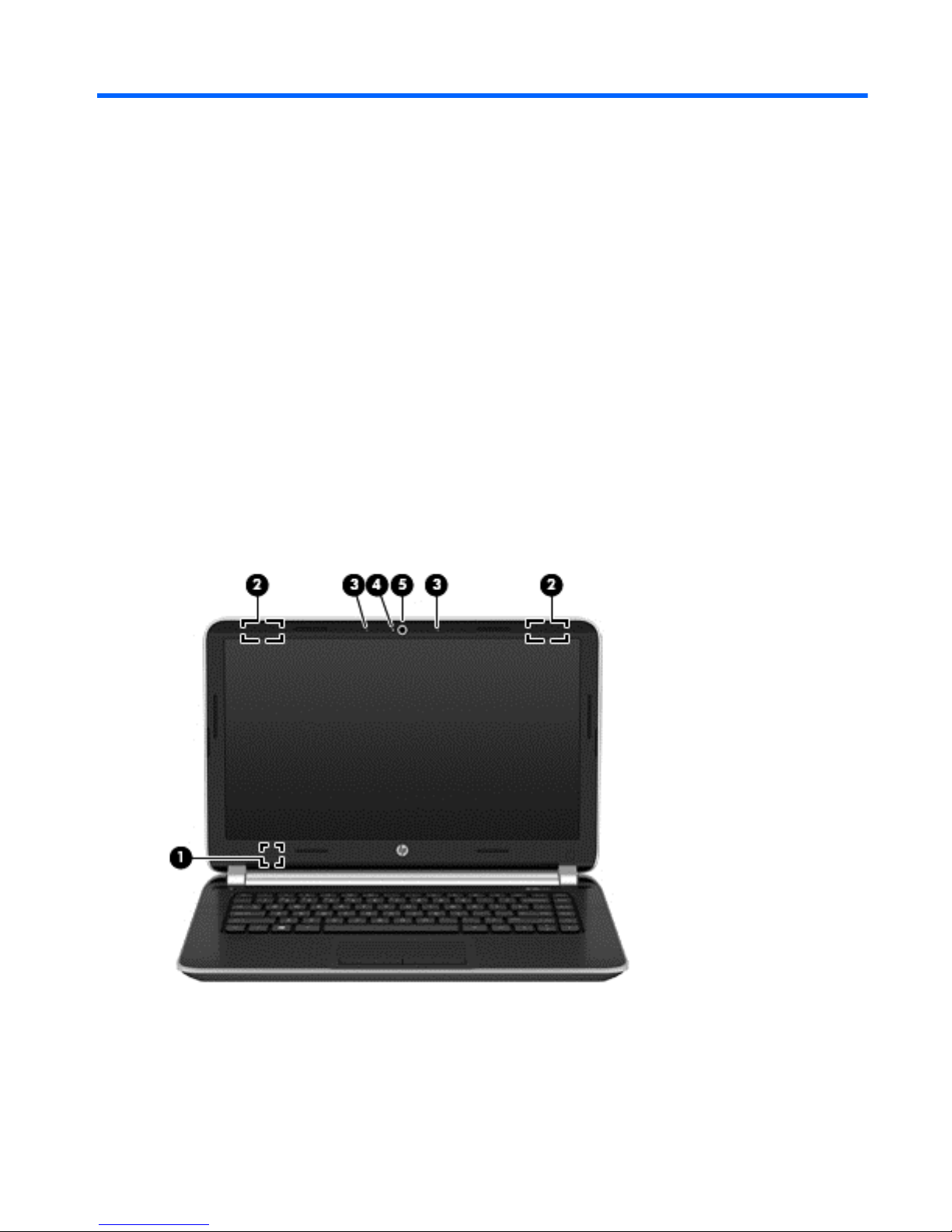
Display
Finding your hardware and software information
5

Item Component Description
(1) Internal display switch Turns off the display and initiates Sleep if the display is
closed while the power is on.
NOTE: The internal display switch is not visible from
the outside of the computer.
(2) WLAN antennas (2)* Send and receive wireless signals to communicate
with WLANs.
NOTE: To set up a WLAN and connect to the Internet,
you need a broadband modem (either DSL or cable)
(purchased separately), high-speed Internet service
purchased from an Internet service provider, and a
wireless router (purchased separately).
(3) Internal microphone Records sound.
(4) Webcam light On: The webcam is in use.
(5) Webcam Records video, captures still photographs, and allows
video conferences and online chat by means of
streaming video.
To use the webcam, select Start > All Programs >
Communication and Chat > CyberLink YouCam.
*The antennas are not visible from the outside of the computer. For optimal transmission, keep the areas immediately around
the antennas free from obstructions. For wireless regulatory notices, see the section of the Regulatory, Safety, and
Environmental Notices that applies to your country or region. These notices are located in Help and Support.
6 Chapter 2 External component identification
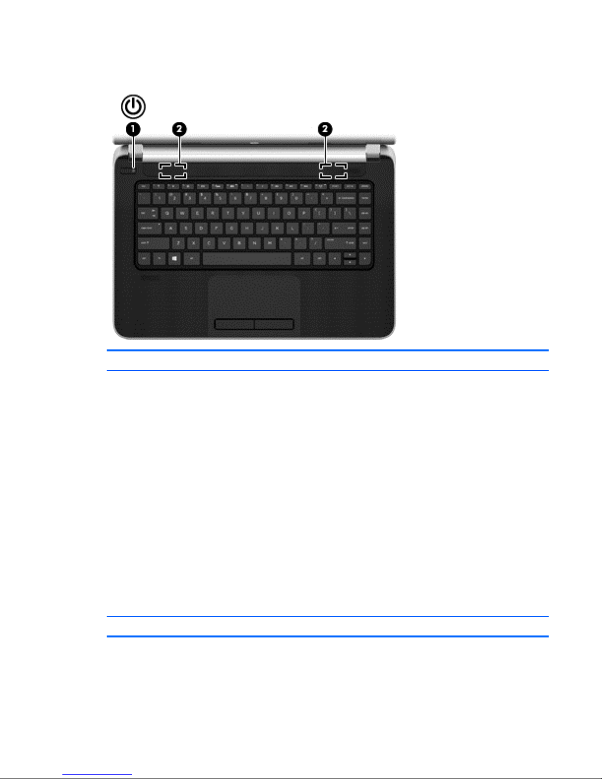
Button
Component Description
(1) Power button
●
When the computer is off, press the button to turn on
the computer.
●
When the computer is on, press the button briefly to
initiate Sleep.
●
When the computer is in the Sleep state, press
the button briefly to exit Sleep.
●
When the computer is in Hibernation, press
the button briefly to exit Hibernation.
CAUTION: Pressing and holding down the power
button will result in the loss of unsaved information.
If the computer has stopped responding and Microsoft
Windows shutdown procedures are ineffective, press and
hold the power button down for at least 5 seconds to turn
off the computer.
To learn more about your power settings, select Start >
Control Panel > System and Security > Power
Options.
(2) Speakers (2) Produce sound.
Button
7
Keys
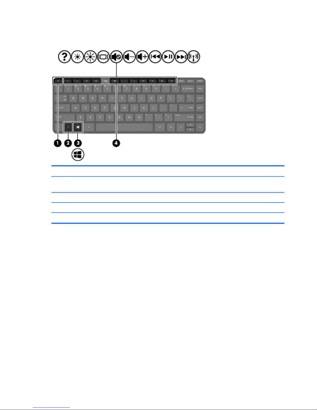
Item Component Description
(1) esc key Displays system information when pressed in combination
with the fn key.
(2) fn key Used in conjunction with hot keys.
(3) Windows logo key Displays the Windows Start menu.
(4) Action keys Execute frequently used system functions.
8 Chapter 2 External component identification
Lights
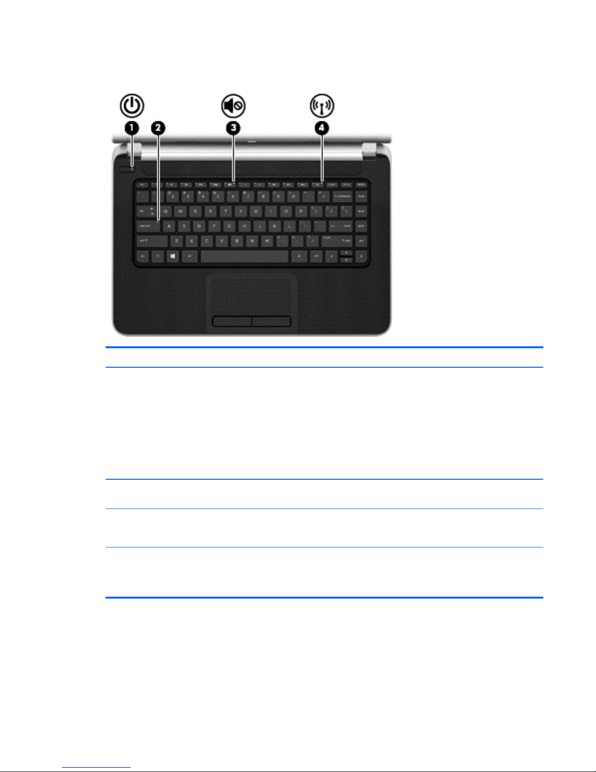
Item Component Description
(1) Power light
●
White: The computer is on.
●
Blinking white: The computer is in the Sleep state,
which is an energy-saving mode. The computer
shuts off power to the display and other
unneeded components.
●
Off: The computer is off or in Hibernation.
Hibernation is an energy-saving mode that uses the
least amount of power.
(2) Caps lock light On: Caps lock is on, which switches the keys to all
capital letters.
(3) Mute light
●
Amber: Computer sound is off.
●
Off: Computer sound is on.
(4) Wireless light
●
White: An integrated wireless device, such as a
WLAN device and/or a Bluetooth device, is on.
●
Amber: All wireless devices are off.
Lights
9
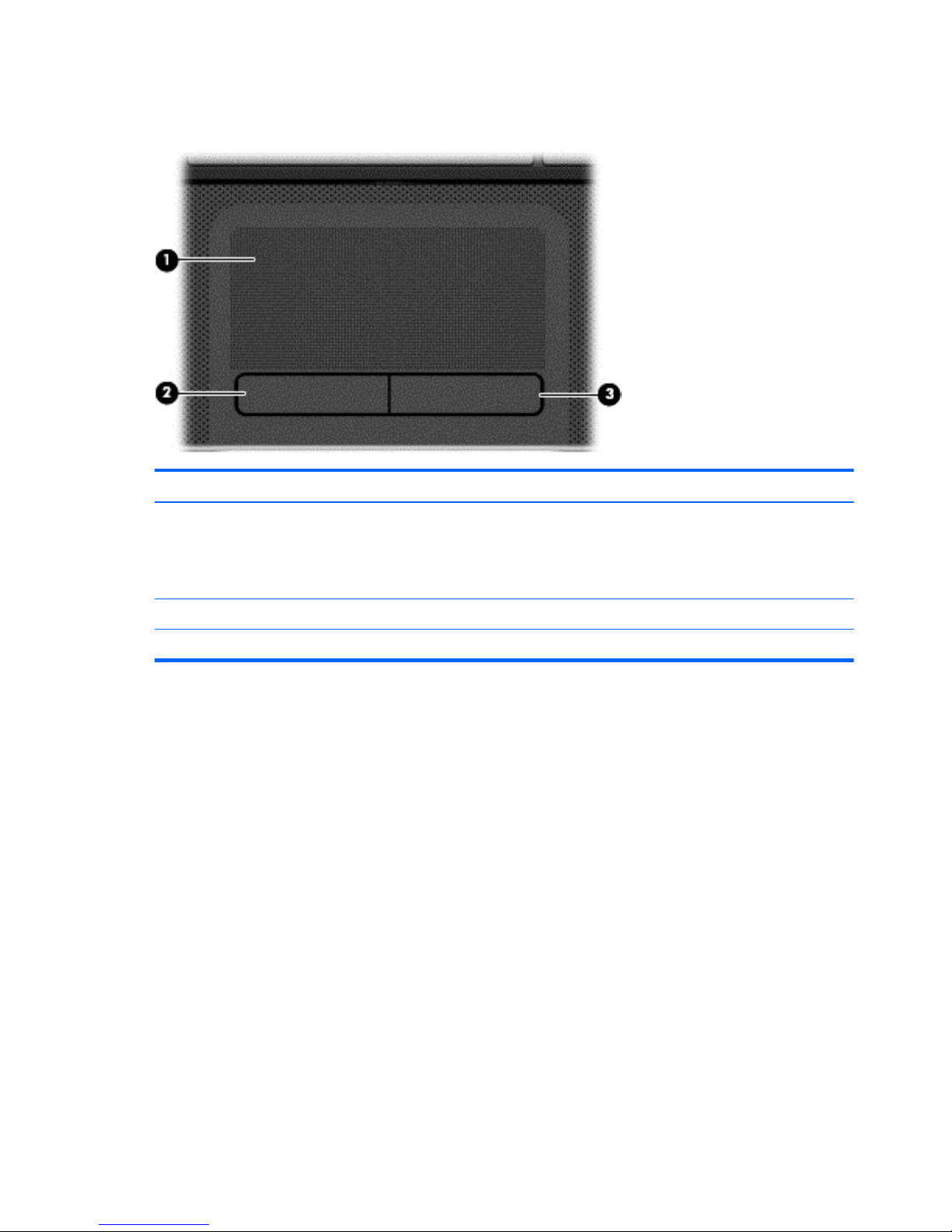
TouchPad
Item Component Description
(1) TouchPad zone Moves the on-screen pointer and selects or activates items
on the screen.
NOTE: The TouchPad also supports edge-swipe
gestures.
(2) Left TouchPad button Functions like the left button on an external mouse.
(3) Right TouchPad button Functions like the right button on an external mouse.
10 Chapter 2 External component identification
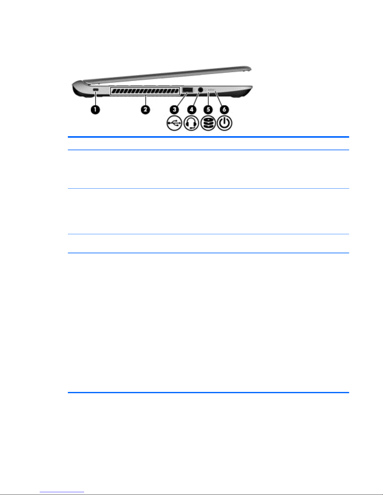
Left side
Item Component Description
(1) Security cable slot Attaches an optional security cable to the computer.
NOTE: The security cable is designed to act as a
deterrent, but it may not prevent the computer from being
mishandled or stolen.
(2) Vent Enable airflow to cool internal components.
NOTE: The computer fan starts up automatically to cool
internal components and prevent overheating. It is
normal for the internal fan to cycle on and off during
routine operation.
(3) USB 3.0 port Connect optional USB 3.0 devices and provide
enhanced USB power performance.
(4) Audio-out (headphone) jack Connects optional powered stereo speakers,
headphones, earbuds, a headset, or a television audio
cable. Also connects an optional headset microphone.
This jack does not support optional microphone-only
devices.
WARNING! To reduce the risk of personal injury,
adjust the volume before putting on headphones,
earbuds, or a headset. For additional safety information,
refer to the Regulatory, Safety, and Environmental
Notices. To access this guide, from the Start screen, type
support, select the HP Support Assistant app, select My
computer, and then select User guides.
NOTE: When a device is connected to the jack,
the computer speakers are disabled.
NOTE: Be sure that the device cable has a 4-conductor
connector that supports both audio-out (headphone) and
audio-in (microphone).
Left side
11

Item Component Description
(5) Hard drive light
●
Blinking white: The hard drive is being accessed.
●
Amber: HP 3D DriveGuard has temporarily parked
the hard drive.
(6) Power light
●
White: The computer is on.
●
Blinking white: The computer is in the Sleep state,
which is an energy-saving mode. The computer shuts
off power to the display and other
unneeded components.
●
Off: The computer is off or in Hibernation.
Hibernation is an energy-saving mode that uses the
least amount of power.
NOTE: For select models, the Intel Rapid Start
Technology feature is enabled at the factory. Rapid Start
Technology allows your computer to resume quickly from
inactivity.
12 Chapter 2 External component identification
Right side
Item Component Description
(1) USB ports Connects an optional USB device.
CAUTION: While there are multiple USB ports on the
same side, only one USB port will able to support a high
power device at a time.
(2) HDMI port Connects an optional video or audio device, such as a
high-definition television, any compatible digital or
audio device.
(3) Memory card reader Reads data from and writes data to digital memory cards
such as Secure Digital (SD).
●
Memory card reader
(4) RJ-45 (network) jack Connects a network cable.
(5) AC adapter light
●
White: The AC adapter is connected and the battery
is charged.
●
Amber: The AC adapter is connected and the
battery is charging.
●
Off: The computer is using DC power.
(6) Power connector Connects an AC adapter.
Right side
13
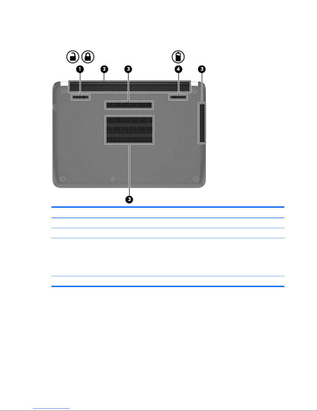
Bottom
Item Component Description
(1) Battery lock/unlock latch Locks battery in place
(2) Battery bay Holds the battery.
(3) Vents (3) Enable airflow to cool internal components.
NOTE: The computer fan starts up automatically to cool
internal components and prevent overheating. It is
normal for the internal fan to cycle on and off during
routine operation.
(4) Battery release latch Releases the battery from the battery bay.
14 Chapter 2 External component identification

3 Illustrated parts catalog
15

Service tag
When ordering parts or requesting information, provide the computer serial number and model
description provided on the service tag.
Item Description Function
(1) Product name This is the product name affixed to the front of
the computer.
(2) Serial number (s/n) This is an alphanumeric identifier that is unique to
each product.
(3) Part number/Product number (p/n) This number provides specific information about the
product's hardware components. The part number
helps a service technician to determine what
components and parts are needed.
(4) Warranty period This number describes the duration of the warranty
period for the computer.
(5) Model description This is the alphanumeric identifier used to locate
documents, drivers, and support for the computer.
16 Chapter 3 Illustrated parts catalog
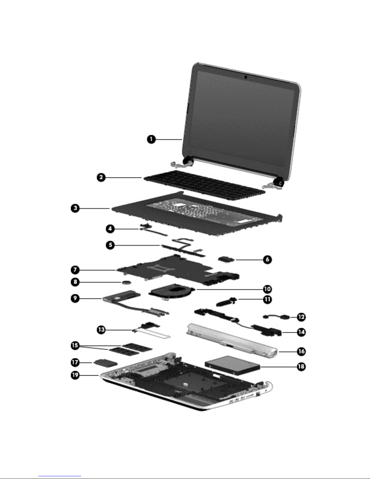
Computer major components
Computer major components
17

Item Component Spare part number
(1) TouchScreen display assembly (14.0-in, HD, LED, BrightView (1366×768), SVA, slim (3.0-mm)
In pearl white finish 732345-001
In sparkling black finish 726201-001
(2) Keyboard (includes keyboard cable):
For use in United States 716164-001
For use in Latin America 716164-161
For use in Canada/England 716164-DB1
For use in United States 722129-001
For use in Latin America 722129-161
For use in England/France 722129-DB1
(3) Top cover (includes the TouchPad board)
In pearl white finish 726209-001
In sparkling black finish 726210-001
(4) Power button board (includes cable) 726203-001
(5) TouchPad button board (includes bracket, TouchPad button board cable, and
TouchPad cable)
726202-001
(6) WLAN module:
Atheros AR9485 802.11b/g/n WiFi Adapter for use on all computer models 675794-001
Ralink RT3290LE 802.11b/g/n 1×1 WiFi and Bluetooth 4.0 Combo Adapter for use
on all computer models
690020-001
Realtek RTL8188EE 802.11bg/n 1×1 WiFi Adapter 709848-001
(7) System board (includes processor and replacement thermal material):
Equipped with an AMD A4-5000 processor (1.50-GHz, 2.00-MB L2 cache, 1600-
MHz DDR3L, quad core, 15 W) and the Linux operating system (includes AMD A76M
FCH, a graphics subsystem with UMA memory, and replacement thermal material)
727199-001
Equipped with an AMD A4-5000 processor (1.50-GHz, 2.00-MB L2 cache, 1600-
MHz DDR3L, quad core, 15 W) and the Windows 8 Standard operating system
(includes AMD A76M FCH, a graphics subsystem with UMA memory, and
replacement thermal material)
727199-501
Equipped with an AMD A6-5200 processor (2.00-GHz, 2.00-MB L2 cache, 1600-
MHz DDR3L, quad core, 25 W) and the Linux operating system (includes AMD A76M
FCH, a graphics subsystem with UMA memory, and replacement thermal material)
727200-001
Equipped with an AMD A6-5200 processor (2.00-GHz, 2.00-MB L2 cache, 1600-
MHz DDR3L, quad core, 25 W) and the Windows 8 Standard operating system
(includes AMD A76M FCH, a graphics subsystem with UMA memory, and
replacement thermal material)
727200-501
18 Chapter 3 Illustrated parts catalog
 Loading...