

Page 1

HP Pavilion G6 Notebook PC
Maintenance and Service Guide
SUMMARY
This guide is a troubleshooting reference used for maintaining and servicing the computer. It provides
comprehensive information on identifying computer features, components, and spare parts;
troubleshooting computer problems; and performing computer disassembly procedures.
Page 2

© Copyright 2011 Hewlett-Packard
Development Company, L.P.
ATI and ATI Mobility Radeon are trademarks
of Advanced Micro Devices, Inc. Bluetooth is
a trademark owned by its proprietor and
used by Hewlett-Packard Company under
license. Intel and Core are trademarks of
Intel corporation in the U.S. and other
countries. Microsoft and Windows are U.S.
registered trademarks of Microsoft
Corporation. SD Logo is a trademark of its
proprietor.
The information contained herein is subject
to change without notice. The only
warranties for HP products and services are
set forth in the express warranty statements
accompanying such products and services.
Nothing herein should be construed as
constituting an additional warranty. HP shall
not be liable for technical or editorial errors
or omissions contained herein.
Fourth Edition: August 2011
Document Part Number: 665584-001
Page 3

Safety warning notice
WARNING! To reduce the possibility of heat-related injuries or of overheating the computer, do not
place the computer directly on your lap or obstruct the computer air vents. Use the computer only on a
hard, flat surface. Do not allow another hard surface, such as an adjoining optional printer, or a soft
surface, such as pillows or rugs or clothing, to block airflow. Also, do not allow the AC adapter to
contact the skin or a soft surface, such as pillows or rugs or clothing, during operation. The computer
and the AC adapter comply with the user-accessible surface temperature limits defined by the
International Standard for Safety of Information Technology Equipment (IEC 60950).
iii
Page 4

iv Safety warning notice
Page 5

Table of contents
1 Product description ........................................................................................................... 1
2 External component identification ..................................................................................... 8
Top ........................................................................................................................................ 8
TouchPad ................................................................................................................. 8
Lights ....................................................................................................................... 9
Button .................................................................................................................... 10
Keys ...................................................................................................................... 11
Front ..................................................................................................................................... 12
Right side .............................................................................................................................. 13
Left side ................................................................................................................................ 14
Display ................................................................................................................................. 16
Bottom .................................................................................................................................. 17
3 Illustrated parts catalog .................................................................................................. 18
Serial number location ............................................................................................................ 18
Computer major components ................................................................................................... 19
Display assembly components ................................................................................................. 27
Mass storage devices ............................................................................................................. 29
Miscellaneous parts ................................................................................................................ 31
Sequential part number listing .................................................................................................. 33
4 Removal and replacement procedures ............................................................................ 41
Preliminary replacement requirements ....................................................................................... 41
Tools required ......................................................................................................... 41
Service considerations ............................................................................................. 41
Plastic parts ............................................................................................. 41
Cables and connectors ............................................................................. 42
Drive handling ......................................................................................... 42
Grounding guidelines .............................................................................................. 43
Electrostatic discharge damage .................................................................. 43
v
Page 6

Packaging and transporting guidelines ........................................ 44
Workstation guidelines .............................................................. 44
Equipment guidelines ................................................................. 45
Component replacement procedures ........................................................................................ 46
Serial number ......................................................................................................... 46
Computer feet ......................................................................................................... 47
Battery ................................................................................................................... 48
Service door ........................................................................................................... 49
Hard drive ............................................................................................................. 50
Optical drive .......................................................................................................... 52
WLAN module ........................................................................................................ 54
Memory module ...................................................................................................... 56
Keyboard ............................................................................................................... 57
Top cover ............................................................................................................... 60
Power button board ................................................................................................. 63
TouchPad button board ............................................................................................ 65
TouchPad LED board ............................................................................................... 67
Speaker assembly ................................................................................................... 68
USB board ............................................................................................................. 69
Power connector ..................................................................................................... 70
Display assembly .................................................................................................... 71
System board ......................................................................................................... 78
RTC battery ............................................................................................................ 82
Heat sink assembly .................................................................................................. 84
Processor ............................................................................................................... 88
5 Specifications .................................................................................................................. 91
Computer specifications .......................................................................................................... 91
39.6-cm (15.6-in) display specifications .................................................................................... 92
Hard drive specifications ........................................................................................................ 93
DVD±RW and CD-RW SuperMulti Double-Layer Combo Drive specifications ................................. 94
Blu-ray Disc ROM and DVD±R/RW SuperMulti Double-Layer Drive specifications .......................... 95
6 Setup Utility (BIOS) ......................................................................................................... 96
Starting Setup Utility ............................................................................................................... 96
Using Setup Utility .................................................................................................................. 96
Changing the language of Setup Utility ...................................................................... 96
Navigating and selecting in Setup Utility .................................................................... 97
Displaying system information ................................................................................... 97
Restoring factory default settings in Setup Utility .......................................................... 97
Exiting Setup Utility ................................................................................................. 97
vi
Page 7

Updating the BIOS ................................................................................................................. 98
Determining the BIOS version ................................................................................... 98
Downloading a BIOS update .................................................................................... 99
7 Backup and recovery .................................................................................................... 100
Restore ............................................................................................................................... 101
Creating restore media ......................................................................................................... 101
Performing a system restore ................................................................................................... 102
Restoring using the dedicated recovery partition (select models only) ........................... 102
Restoring using the restore media ............................................................................ 103
Changing the computer boot order .......................................................................... 104
Backing up and recovering your information ........................................................................... 104
Using Windows Backup and Restore ....................................................................... 105
Using Windows system restore points ...................................................................... 106
When to create restore points .................................................................. 106
Create a system restore point ................................................................... 106
Restore to a previous date and time .......................................................... 106
8 Power cord set requirements ........................................................................................ 107
Requirements for all countries ................................................................................................ 107
Requirements for specific countries and regions ....................................................................... 108
9 Recycling ...................................................................................................................... 110
Index ............................................................................................................................... 111
vii
Page 8

viii
Page 9

1 Product description
Category Description Intel® AMD®
Discrete UMA Discrete UMA
HP Pavilion G6 Notebook PC √√ √ √
Processors Intel® Core™ i7-2620M processor (2.7 GHz,
SC turbo up to 3.40 GHz, 4 MB L3 cache),
Dual 35 W
Intel Core i5-2540M processor (2.6 GHz, SC
turbo up to 3.3 GHz, 3 MB L3 cache), Dual 35
W
Intel Core i5-2520M processor (2.5 GHz, SC
turbo up to 3.2 GHz, 3 MB L3 cache), Dual 35
W
Intel Core i5-2430M processor (2.4 GHz, SC
turbo up to 3.0 GHz, 3 MB L3 cache), Dual 35
W
Intel Core i5-2410M processor (2.3 GHz, SC
turbo up to 2.9 GHz, 3 MB L3 cache), Dual 35
W
Intel Core i3-2350M processor (2.3 GHz, 3 MB
L3 cache) Dual 35 W
Intel Core i3-2330M processor (2.2 GHz, 3 MB
L3 cache) Dual 35 W
Intel Core i3-2310M processor (2.1 GHz, 3 MB
L3 cache) Dual 35 W
√√
√√
√√
√√
√√
√√
√√
√√
Intel Core i5-480M processor (2.66 GHz, SC
turbo up to 2.93 GHz, 3 MB L3 cache), Dual
35 W
Intel Core i3-390M processor (2.66 GHz, 3 MB
L3 cache), Dual 35 W
Intel Core i3-380M processor (2.53 GHz, 3 MB
L3 cache), Dual 35 W
Intel Pentium B960 processor (2.2 GHz, 2 MB
L3 cache) Dual 35 W
√√
√√
√√
√√
1
Page 10

Category Description Intel® AMD®
Discrete UMA Discrete UMA
Intel Pentium B950 processor (2.1 GHz, 2 MB
L3 cache) Dual 35W
Intel Pentium P6300 (2.26 GHz, 3 MB L3
cache), Dual 35 W
Intel Pentium P6200 (2.13 GHz, 3 MB L3
cache), Dual 35 W
AMD E Series E450 (1.65 GHz, 1 MB L2
cache, 1333MHz), Dual 18 W
AMD A Series APU A8-3500M (2.4 GHz/1.5
GHz, 4 MB L2 cache), Quad 35 W
AMD A Series APU A6-3400M (2.3G Hz/1.4
GHz, 4 MB L2 cache), Quad 35 W
AMD A Series APU A4-3300M (2.5 GHz/1.9G
Hz, 2 MB L2 cache), Dual 35 W
AMD A Series APU E2-3000M (2.4 GHz/1.8
GHz, 1 MB L2 cache), Dual 35 W
AMD Phenom II N970 processor (2.2 GHz, 2
MB L2 cache, 1333 MHz, 3.6 GT/s), Quad 35
W
AMD Phenom II P960 processor (1.8 GHz, 2
MB L2 cache, 1066 MHz, 3.6 GT/s), Quad 25
W
√√
√√
√√
√
√√
√√
√√
√√
√√
√√
AMD Phenom II N870 processor (2.3 GHz, 1.5
MB L2 cache, 1333 MHz, 3.6 GT/s), Triple 35
W
AMD Phenom II P860 processor (2.0 GHz, 1.5
MB L2 cache, 1066 MHz, 3.6 GT/s), Triple 25
W
AMD Phenom II N850 processor (2.2 GHz, 1.5
MB L2 cache, 1333 MHz, 3.6 GT/s), Triple 35
W
AMD Phenom II N660 processor (3.0 GHz, 2
MB L2 cache, 1333 MHz, 3.6 GT/s), Dual 35
W
Chipset Intel HM65 Express Chipset (Intel 2nd
Generation, B9xx Processors)
Intel HM55 Express Chipset (Intel Previous
Generation Processors)
AMD A50M FCH (AMD E-Series Processors) √
AMD A60M FCH (AMD A Series Processors) √√
√√
√√
√√
√√
√√
√√
2 Chapter 1 Product description
Page 11

Category Description Intel® AMD®
Discrete UMA Discrete UMA
AMD RS880M + SB820M (AMD Phenom,
Turion, Athlon, V Series Processors)
Graphics Intel HD Graphics 3000 √
Intel HD Graphics √√ √
ATI Radeon™ HD 6470M with 512 MB of
dedicated video memory
ATI Radeon HD 6470M with 1 GB of dedicated
video memory (128 Mx16 DDR3, 900 MHz×4
PCs)
nVidia® N12P-GV (NVIDIA GeForce® GT
520M with 1024MB of dedicated video
memory (128 Mx16 DDR3 900MHz x 4 PCs)
AMD Radeon™ HD 6320 √
AMD Radeon HD 6620G √
AMD Radeon HD 6520G √
AMD Radeon HD 6480G √
AMD Radeon HD 6380G √
AMD Radeon HD 6640G2 √
√√
√ √
√ √
√
AMD Radeon HD 6540G2 √
AMD Radeon HD 6510G2 √
Support for HD-DVD playback with HD decoder
and DX11 and HDMI
Panel 39.6-cm (15.6-in) HD LED BrightView
(1366×768)
16:9 wide aspect ratio √√ √ √
Memory 2 customer-accessible/upgradable SODIMM
slots:
Supports up to 6 GB of system memory in the
DDR3-1333 MHz Dual Channel Support
●
(Intel 2nd Generation Processors, All AMD
Processors Except AMD E Series)
DDR3-1333 MHz Single channel support
●
(AMD E Series Processors)
DDR3-1066 MHz Dual Channel Support
●
(DDR3-1333 downgraded to DDR3-1066)
(Intel Previous Generation Processors)
following configurations:
√√ √ √
√√ √ √
√√
√
√√
6144 MB (4096 MB × 1 + 2048×1) √√ √ √
●
3
Page 12

Category Description Intel® AMD®
Discrete UMA Discrete UMA
Hard drives Supports the following 9.5 mm, 6.35-cm (2.5
Supports the following 7 mm, 6.35-cm (2.5
4096 MB (4096 MB × 1) √√ √ √
●
4096 MB (2048 MB × 2) √√ √ √
●
3072 MB (1024 MB × 1 + 2048 MB × 1) √√ √ √
●
2048 MB (2048 MB × 1) √√ √ √
●
2048 MB (1024 MB × 2) √√ √ √
●
1024 MB (1024 MB × 1) √√ √ √
●
in) SATA hard drives:
750 GB, 5400 rpm √√ √ √
●
640 GB, 5400 rpm √√ √ √
●
500 GB, 7200 rpm; 5400 rpm √√ √ √
●
320 GB, 5400 rpm √√ √ √
●
in) SATA hard drives:
320 GB, 7200 rpm √√ √ √
●
250 GB, 7200 rpm √√ √ √
●
Optical drives 12.7 mm (0.50-in) fixed SATA tray load √√ √ √
DVD±RW and CD-RW SuperMulti Double-Layer
Combo Drive
Blu-ray Disc ROM with DVD±R/RW SuperMulti
Double-Layer Drive
Non-optical drive support (protective insert
feature)
Webcam VGA camera (640x480 by 24 frames per
second), fixed angle (no tilt), with activity light
and single digital microphone
Audio High-definition audio supports:
Microsoft® premium requirements with HP Altec
Lansing speakers
SRS Premium Sound technology
Ethernet Integrated 10/100 network interface card (NIC) √√ √ √
Integrated wireless local area network (WLAN)
options by way of wireless module and 2
wireless antennas built into display assembly
Supports the following WLAN formats:
√√ √ √
√√ √ √
√√ √ √
√√ √ √
√√ √ √
√√ √ √
4 Chapter 1 Product description
Page 13

Category Description Intel® AMD®
Discrete UMA Discrete UMA
Intel Centrino® Wireless-N 1030 +
●
Bluetooth (802.11b/g/n)
Intel Centrino Wireless-N 1000 (802.11b/
●
g/n) with WiDi
Atheros AR9285 802.11b/g/n 1x1 WiFi
●
Adapter
Ralink 5390GN 802.11b/g/n 1x1 WiFi
●
Adapter
Broadcom 4313 802.11b/g/n 1x1 WiFi
●
and 2070 Bluetooth 2.1+EDR Combo
adapter (BT3.0+HS ready)
Broadcom 4313GN 802.11b/g/n 1x1
●
WiFi Adapter
Broadcom 4313AGN 802.11a/b/g/
●
draft-n WiFi Adapter
Ralink 5390BC8 802.11b/g/n 1x1 WiFi
●
and Bluetooth 3.0+HS Combo Adapter
Realtek 8188GN 802.11b/g/n 1x1 WiFi
●
Adapter
Atheros 9485GN 802.11b/g/n 1x1 WiFi
●
and 3012 Bluetooth 4.0 Combo Adapter
√√
√√
√√ √ √
√√ √ √
√√ √ √
√√ √ √
√√
√√ √ √
√√ √ √
√√ √ √
External media
card
Internal card One half-size Mini Card slot for WLAN √√ √ √
Ports Audio-in (digital microphone) √√ √ √
Audio-out (stereo headphone) √√ √ √
High-Definition Multimedia Interface (HDMI)
Hot plug/unplug with auto-detect for correct
RJ-45 (Ethernet) √√ √ √
Three USB 2.0 ports √√ √ √
Realtek 8188BC8 802.11a/b/g/n 2x2
●
WiFi and Bluetooth 3.0+HS Combo
Adapter
Atheros AR9002WB-1NGB 802.11b/g/n
●
1x1 WiFi and Bluetooth 2.1+EDR Combo
Adapter
Digital Media Slot supporting SD, SDHC, SDXC
(UHS104 compliant), and MMC
version 1.4 supporting up to 1920x1200 @ 60
Hz
output to wide-aspect vs. standard aspect video
√√
√√
√√ √ √
√√ √ √
√√ √ √
5
Page 14

Category Description Intel® AMD®
Discrete UMA Discrete UMA
VGA (Dsub 15-pin) supporting the following:
2048×1536 external resolution @ 75 Hz
●
1920×1600 external resolution @ 60 Hz
●
2048×1536 external resolution @ 60 Hz
●
(for E450 processor)
2560×1600 external resolution @ 60 Hz
●
(for E350 processor)
HDMI v1.4 supporting: up to 1080p,
1920x1200 @ 60 Hz and 1920x1200 @
60 Hz DVI Mode
AC Smart Pin adapter √√ √ √
Keyboard/
pointing devices
TouchPad with 2 buttons (multitouch gestures,
Power
requirements
39.62-cm (15.6-in), full-size keyboard
Textured Pocket Keyboard (Black)
●
Painted Pocket Keyboard (Pink)
●
and taps enabled as default). Taps enabled as
default.
6-cell, 2.22 Ah, 47 Wh battery √√ √ √
√√ √ √
√√ √ √
√√ √ √
6-cell, 2.55 Ah, 55 Wh battery √√ √ √
Batteries support fast charge √√ √ √
65-W AC Smart adapter with localized cable
plug support
90-W AC Smart adapter with localized cable
plug support
Security Security lock √√ √ √
Operating
system
Windows® 7® Professional (32 and 64 bit) √√
Windows 7 Home Premium (32 & 64 bit) √√ √ √
Windows 7 Home Basic (32 and 64 bit) √√ √ √
Windows 7 Starter (32 bit) √√
FreeDOS √√ √ √
Serviceability End-user replaceable parts:
AC adapter √√ √ √
Preinstalled:
√ √
√ √
6 Chapter 1 Product description
Page 15

Category Description Intel® AMD®
Discrete UMA Discrete UMA
Battery (system) √√ √ √
Hard drive √√ √ √
Memory module √√ √ √
Optical drive √√ √ √
7
Page 16
2 External component identification
Top
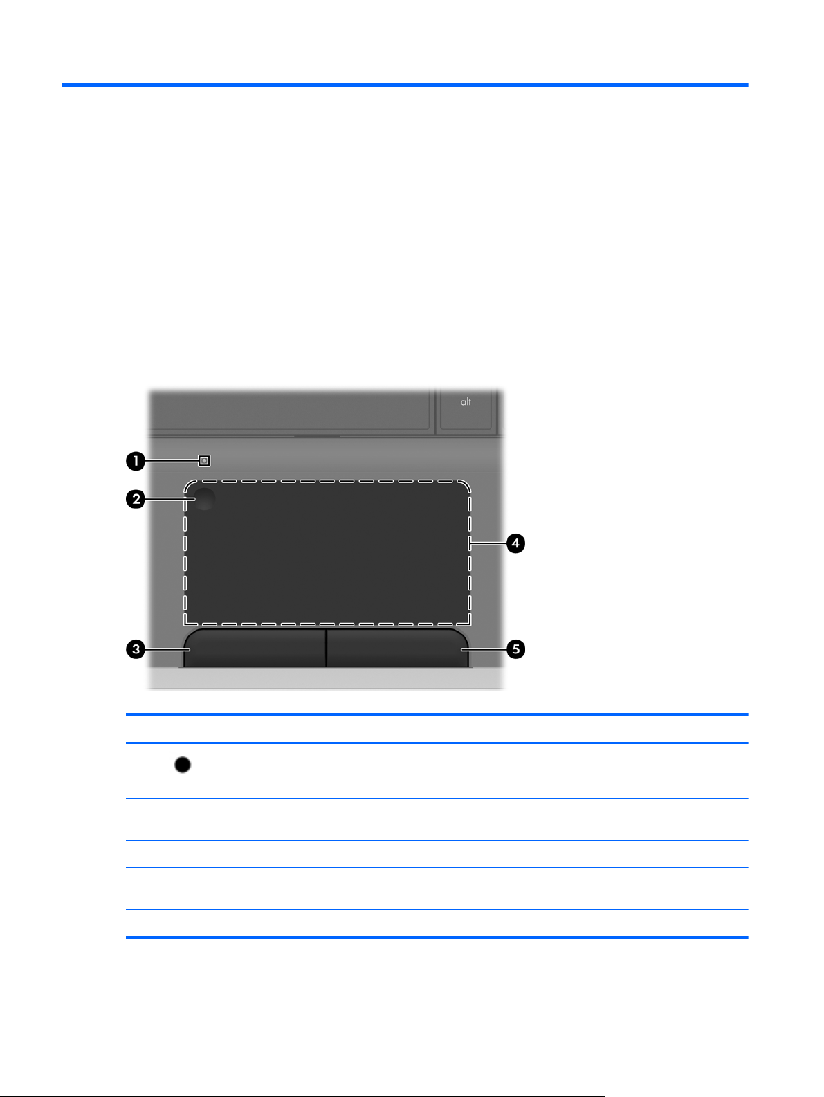
TouchPad
Component Description
(1)
(2) TouchPad on/off button Turns the TouchPad on and off. Quickly double-tap the
(3) Left TouchPad button Functions like the left button on an external mouse.
(4) TouchPad zone Moves the pointer and selects or activates items on the
(5) Right TouchPad button Functions like the right button on an external mouse.
TouchPad light
8 Chapter 2 External component identification
Off: The TouchPad is on.
●
Amber: The TouchPad is off.
●
TouchPad button to turn the TouchPad on and off.
screen.
Page 17
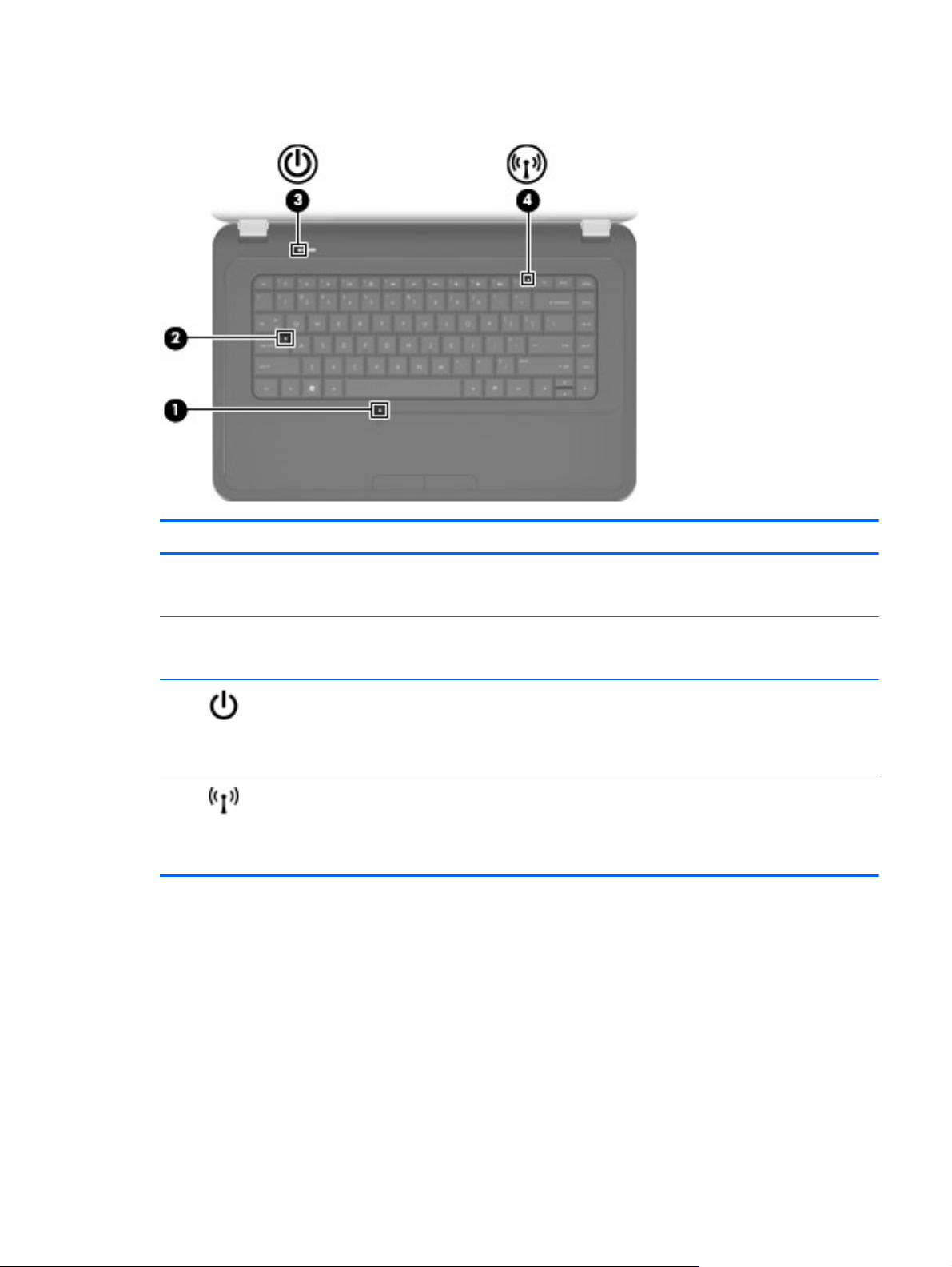
Lights
Component Description
(1) TouchPad light
(2) Caps lock light
(3)
(4)
Power light
Wireless light
Off: The TouchPad is on.
●
Amber: The TouchPad is off.
●
White: Caps lock is on.
●
Off: Caps lock is off.
●
On: The computer is on.
●
Blinking: The computer is in Sleep mode.
●
Off: The computer is off or in Hibernation mode.
●
White: An integrated wireless device, such as a wireless
●
local area network (WLAN) device and/or a
Bluetooth® device, is on.
Amber: All wireless devices are off.
●
Top
9
Page 18
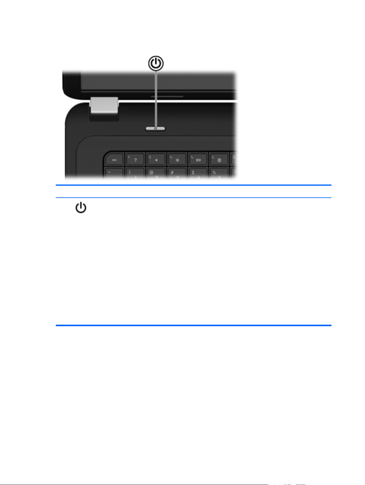
Button
Component Description
Power button
When the computer is off, press the power button to
●
turn on the computer.
When the computer is on, press the power button
●
briefly to initiate Sleep mode.
When the computer is in Sleep mode, press the power
●
button briefly to exit Sleep mode.
When the computer is in Hibernation mode, press the
●
power button briefly to exit Hibernation mode.
If the computer has stopped responding and Windows
shutdown procedures are ineffective, press and hold the
power button for at least 5 seconds to turn off the computer.
To learn more about your power settings, select Start >
Control Panel > System and Security > Power
Options, or refer to the HP Notebook Reference Guide.
10 Chapter 2 External component identification
Page 19
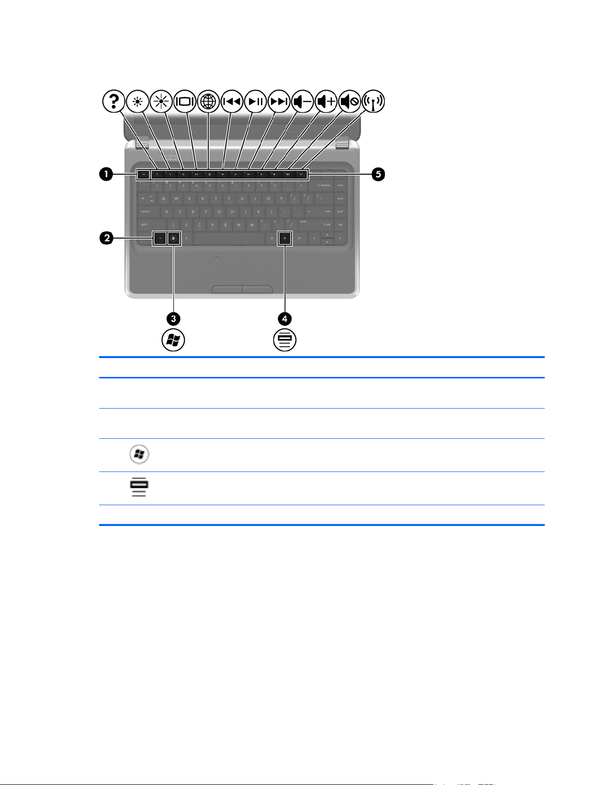
Keys
Component Description
(1) esc key Displays system information when pressed in combination
with the fn key.
(2) fn key Displays system information when pressed in combination
with the esc key.
(3)
(4)
(5) Action keys Execute frequently used system functions.
Windows logo key Displays the Windows Start menu.
Windows applications key Displays a shortcut menu for items beneath the pointer.
Top
11
Page 20

Front
Component Description
Speakers (2) Produce sound.
12 Chapter 2 External component identification
Page 21
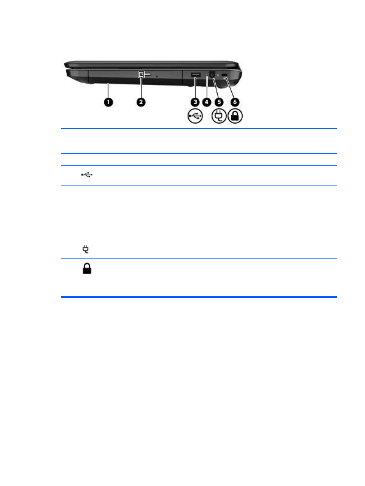
Right side
Component Description
(1) Optical drive Plays optical discs, such as CDs, DVDs, and Blu-ray discs.
(2) Optical drive light Green: The optical drive is being accessed.
(3)
(4) AC adapter light
(5)
(6)
USB port Connects an optional USB device.
Power connector Connects an AC adapter.
Security cable slot Attaches an optional security cable to the computer.
Blinking white: The battery is low.
●
Solid white: The computer is connected to external
●
power.
Amber: The computer is charging the battery.
●
Off: The computer is not connected to external power.
●
NOTE: The security cable is designed to act as a
deterrent, but it may not prevent the computer from being
mishandled or stolen.
Right side
13
Page 22
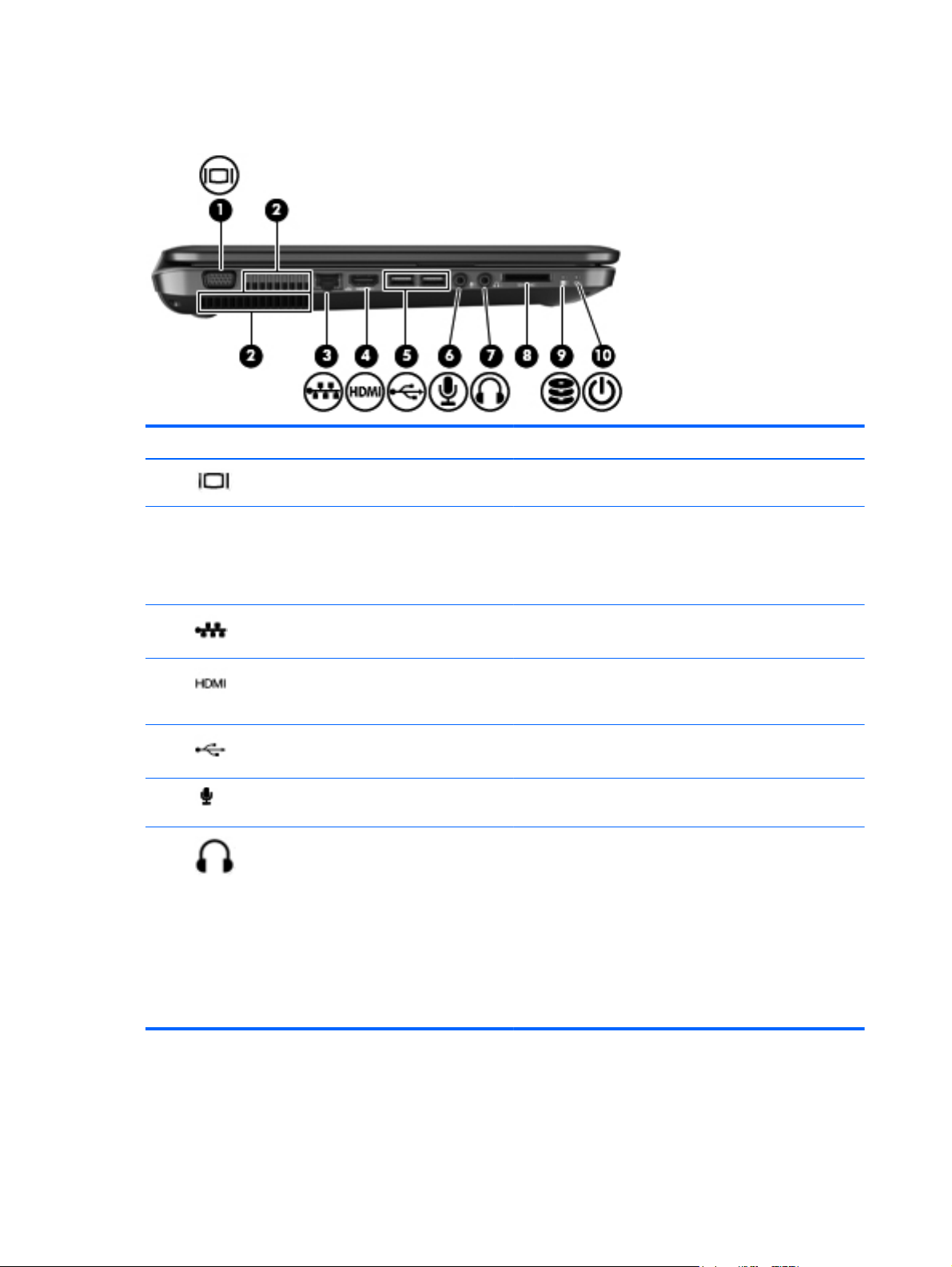
Left side
Component Description
(1)
(2) Vents (2) Enable airflow to cool internal components.
(3)
(4)
(5)
(6)
(7)
External monitor port Connects an external VGA monitor or projector.
NOTE: The computer fan starts up automatically to cool
internal components and prevent overheating. It is normal for
the internal fan to cycle on and off during routine operation.
RJ-45 (network) jack Connects a network cable.
HDMI port Connects an optional video or audio device, such as a high-
definition television, or any compatible digital or audio
component.
USB ports (2) Connect optional USB devices.
Audio-in (microphone) jack Connects an optional computer headset microphone, stereo
array microphone, or monaural microphone.
Audio-out (headphone) jack Produces sound when connected to optional powered stereo
speakers, headphones, earbuds, a headset, or television
audio.
WARNING! To reduce the risk of personal injury, adjust
the volume before putting on headphones, earbuds, or a
headset. For additional safety information, refer to the
Regulatory, Safety and Environmental Notices.
14 Chapter 2 External component identification
NOTE: When a device is connected to the jack, the
computer speakers are disabled.
Page 23

Component Description
(8) Digital Media Slot Supports the following optional digital card formats:
MultiMedia Card (MMC)
●
Secure Digital (SD) Memory Card
●
Secure Digital High Capacity (SDHC) Memory Card
●
Secure Digital Extended Capacity (SDXC) Memory
●
Card
(9)
(10)
Hard drive light
Power light
White: The hard drive is being accessed.
●
White: The computer is on.
●
Blinking white: The computer is in Sleep mode.
●
Left side
15
Page 24
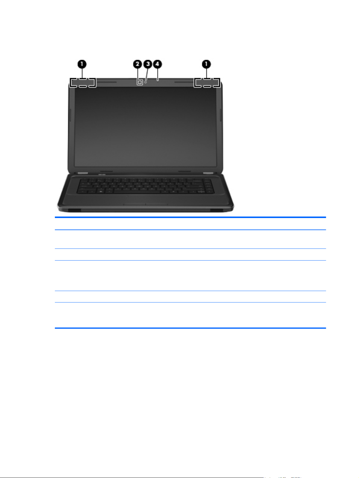
Display
Component Description
(1) WLAN antennas (2)* Send and receive wireless signals to communicate with wireless
local area networks (WLANs).
(2) Webcam light On: The webcam is in use.
(3) Webcam Records video and captures still photographs.
To use the webcam, select Start> All Programs >Cyberlink
YouCam
(4) Internal microphone Records sound.
*The antennas are not visible from the outside of the computer. For optimal transmission, keep the areas immediately around
the antennas free from obstructions. To see wireless regulatory notices, refer to the section of the Regulatory, Safety and
Environmental Notices that applies to your country or region. These notices are located in Help and Support.
16 Chapter 2 External component identification
Page 25
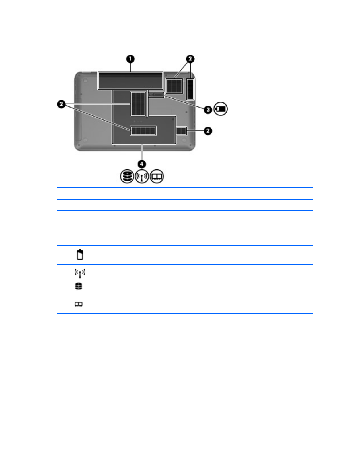
Bottom
Component Description
(1) Battery bay Holds the battery.
(2) Vents (5) Enable airflow to cool internal components.
NOTE: The computer fan starts up automatically to cool
internal components and prevent overheating. It is normal for
the internal fan to cycle on and off during routine operation.
(3)
(4)
Battery release latch Releases the battery from the battery bay.
Service door Provides access to the hard drive, wireless modules, and
memory modules.
Bottom
17
Page 26
3 Illustrated parts catalog
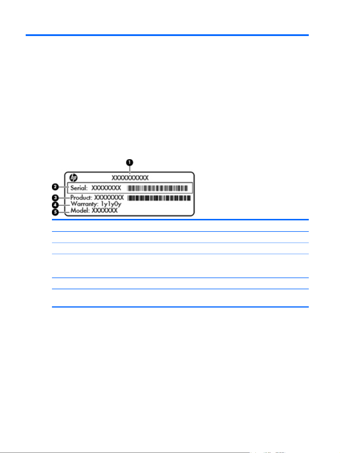
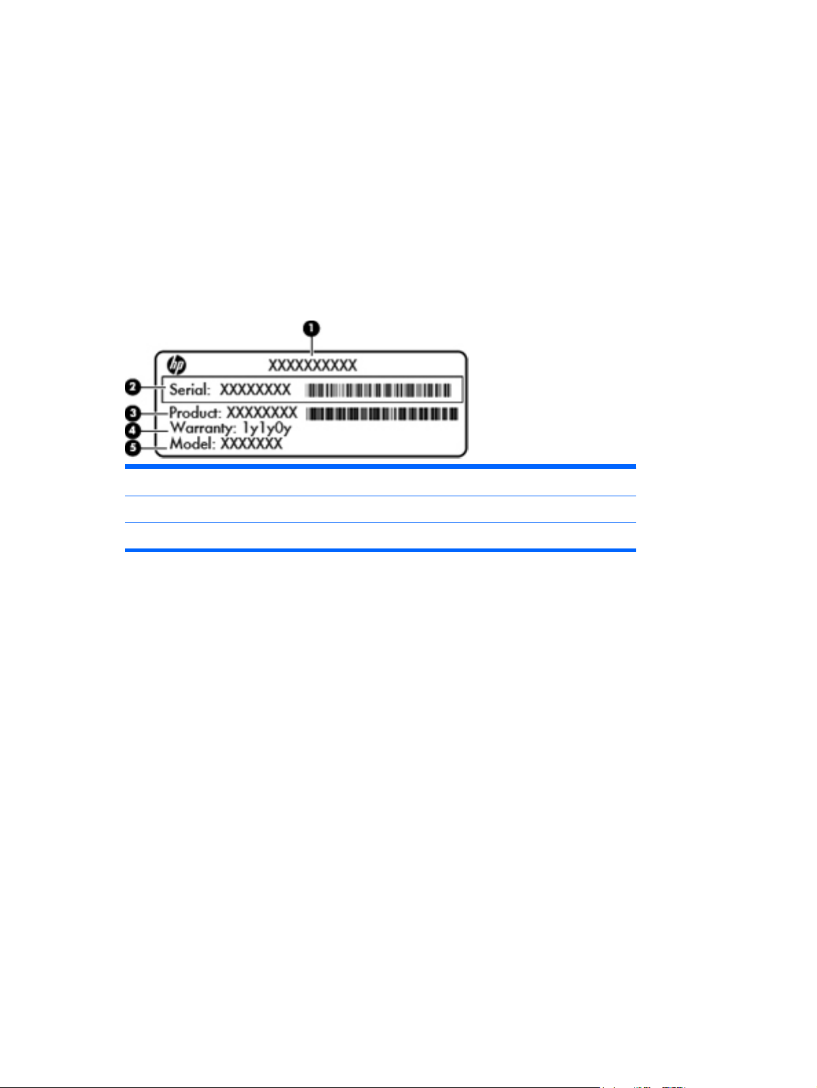
Serial number location
When ordering parts or requesting information, provide the computer serial number and model number
located in the battery bay of the computer.
Component Description
(1) Product name The name affixed to the front of the computer.
(2) Serial number (s/n) An alphanumeric identifier that is unique to each product.
(3) Product number This number provides specific information about the product’s
hardware components. The product number helps a service
technician to determine what components and parts are needed.
(4) Warranty period The duration of the warranty period for the computer.
(5) Model description An alphanumeric identifier used to locate documents, drivers, and
support for the computer.
18 Chapter 3 Illustrated parts catalog
Page 27
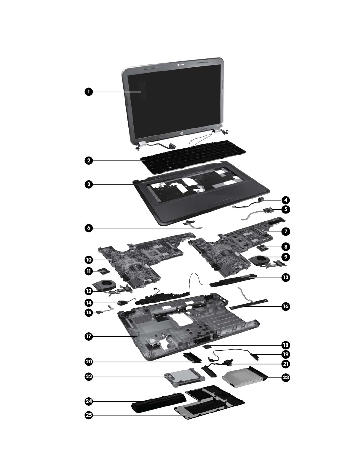
Computer major components
Computer major components
19
Page 28

Item Description Spare part number
(1) 39.6-cm (15.6-in) High Definition (HD), light-emitting diode (LED),
BrightView (1366×768) display assembly:
NOTE: For more information on the display assembly internal component spare part
information, see
(2) Keyboard (includes keyboard cable):
For use in Charcoal Grey computer models 645523-001
●
For use in Ocean Drive computer models 636378-001
●
For use in Sonoma Red computer models 645521-001
●
For use in Luminous Rose computer models 645522-001
●
For use in Pewter computer models 645524-001
●
For use in Pacific Blue computer models 645525-001
●
For use in Pearl Pink computer models 645526-001
●
For use in Sweet Purple computer models 645527-001
●
For use in Butter Gold computer models 645528-001
●
For use in the United States, Black 636376-001
●
For use in French Canada, Black 636376-121
●
Display assembly components on page 27.
For use in the United Kingdom, Black 636376-031
●
For use in Germany, Black 636376-041
●
For use in France, Black 636376-051
●
For use in Italy, Black 636376-061
●
For use in Spain, Black 636376-071
●
For use in Portugal, Black 636376-131
●
For use in Turkey, Black 636376-141
●
For use in Saudi Arabia, Black 636376-171
●
For use in Hungary, Black 636376-211
●
For use in Czechoslovakia, Black 636376-221
●
For use in Russia, Black 636376-251
●
For use in Europe, Black 636376-A41
●
For International use, Black 636376-B31
●
For use in the Adriatics, Black 636376-BA1
●
For use in Israel, Black 636376-BB1
●
For use in Switzerland, Black 636376-BG1
●
For use in the Netherlands, Black 636376-DH1
●
20 Chapter 3 Illustrated parts catalog
Page 29

Item Description Spare part number
For use in Greece, Black 636376-DJ1
●
For use in Bulgaria, Black 636376–261
●
For use in Thailand, Black 636376–281
●
For use in Japan, Black 636376–291
●
For use in Taiwan, Black 636376–AB1
●
For use in Korea, Black 636376–AD1
●
For use in India, Black 636376–D61
●
For use in the United States, Pink 645893-001
●
For use in French Canada, Pink 645893-121
●
For use in the United Kingdom, Pink 645893-031
●
For use in Germany, Pink 645893-041
●
For use in France, Pink 645893-051
●
For use in Italy, Pink 645893-061
●
For use in Spain, Pink 645893-071
●
For use in Portugal, Pink 645893-131
●
For use in Turkey, Pink 645893-141
●
For use in Saudi Arabia, Pink 645893-171
●
For use in Hungary, Pink 645893-211
●
For use in Czechoslovakia, Pink 645893-221
●
For use in Russia, Pink 645893-251
●
For use in Europe, Pink 645893-A41
●
For International use, Pink 645893-B31
●
For use in the Adriatics, Pink 645893-BA1
●
For use in Switzerland, Pink 645893-BG1
●
For use in the Netherlands, Pink 645893-DH1
●
For use in Greece, Pink 645893-DJ1
●
For use in Bulgaria, Pink 645893–261
●
For use in Thailand, Pink 645893–281
●
For use in Japan, Pink 645893–291
●
For use in Taiwan, Pink 645893–AB1
●
For use in Korea, Pink 645893–AD1
●
For use in Isreal, Pink 645893–BB1
●
Computer major components
21
Page 30

Item Description Spare part number
(3) Top cover (includes TouchPad board):
(4) Power connector (includes cable) 641137-001
(5) USB board (includes cable) 641145-001
(6) Power button board (includes cable) 641144-001
(7 &
10)
For use in India, Pink 645893–D61
●
For use in Ocean Drive computer models 637196-001
●
For use in Luminous Rose computer models 641287-001
●
For use in Sweet Purple computer models 641297-001
●
For use in Butter Gold computer models 641299-001
●
For use in Pewter computer models 641291-001
●
For use in Charcoal Grey computer models 641289-001
●
For use in Sonoma Red computer models 641285-001
●
For use in Pacific Blue computer models 641293-001
●
For use in Pearl Pink computer models 641295-001
●
System board (includes replacement thermal material):
For use in Intel HM55 UMA computer models 636370-001
●
For use in Intel HM65 UMA computer models 636373-001
●
For use in Intel HM55 6470 discrete, 512 MB, computer models 636371-001
●
For use in Intel HM55 6470 discrete, 1 GB, computer models 636372-001
●
For use in Intel HM65 6470 discrete, 512 MB, computer models 636374-001
●
For use in Intel HM65 6470 discrete, 512 MB, BACO, computer models 650198-001
●
For use in Intel HM65 6470 discrete, 1 GB BACO, computer models 650199-001
●
For use in Intel HM65 6470 discrete, 1 GB, computer models 636375-001
●
For use in AMD UMA computer models 638856-001
●
For use in AMD 6470 discrete, 512 MB computer models 638854-001
●
For use in AMD 6470 discrete, 1 GB computer models 638855-001
●
For use in AMD E-350 UMA computer models 645529-001
●
For use in AMD 880MD 6470 discrete, 512 MB, BACO computer models 647626-001
●
For use in AMD 880MD 6470 discrete, 1 GB, BACO computer models 647627-001
●
For use in AMD A60M UMA computer models 649948-001
●
For use in AMD A60M HD6470 discrete, 512 MB computer models 649949-001
●
For use in AMD A60M HD6470 discrete, 1 GB computer models 649950-001
●
22 Chapter 3 Illustrated parts catalog
Page 31

Item Description Spare part number
(8 &
11)
For use in Intel HM55 i3–370M discrete, 512 MB/1 GB computer models 654117–001
●
For use in Intel HM55 i3–370M UMA computer models 654118–001
●
Processor (includes replacement thermal material)
Intel Core i7-2620M processor (2.7 GHz, SC turbo up to 3.40 GHz, 4 MB L3
●
cache), Dual 35 W
Intel Core i5-2540M processor (2.6 GHz, SC turbo up to 3.3 GHz, 3 MB L3 cache),
●
Dual 35 W
Intel Core i5-2520M processor (2.5 GHz, SC turbo up to 3.2 GHz, 3 MB L3 cache),
●
Dual 35 W
Intel Core i5-2430M processor (2.4 GHz, SC turbo up to 3.0GHz, 3 MB L3 cache),
●
Dual 35 W
Intel Core i5-2410M processor (2.3 GHz, SC turbo up to 2.9 GHz, 3 MB L3 cache),
●
Dual 35 W
Intel Core i3-2350M processor (2.3 GHz, 3 MB L3 cache) Dual 35 W 653340-001
●
Intel Core i3-2330M processor (2.2 GHz, 3 MB L3 cache) Dual 35 W 653339-001
●
Intel Core i3-2310M processor (2.1 GHz, 3 MB L3 cache) Dual 35 W 638037-001
●
Intel Core i5-480M processor (2.66 GHz, SC turbo up to 2.93 GHz, 3 MB L3
●
cache), Dual 35 W
631252-001
631255-001
631253-001
653341-001
638039-001
634693-001
Intel Core i3-390M processor (2.66 GHz, 3 MB L3 cache), Dual 35 W 634692-001
●
Intel Core i3-380M processor (2.53 GHz, 3 MB L3 cache), Dual 35 W 625823-001
●
Intel Pentium B960 processor (2.2 GHz, 2 MB L3 cache), Dual 35 W 664662-001
●
Intel Pentium B950 processor (2.1 GHz, 2 MB L3 cache), Dual 35 W 653338-001
●
Intel Pentium P6300 processor (2.26 GHz, 3 MB L3 cache), Dual 35 W 635500-001
●
Intel Pentium P6200 processor (2.13 GHz, 3 MB L3 cache), Dual 35 W 625831-001
●
AMD A Series APU A8-3500M (2.4 GHz/1.5 GHz, 4 MB L2 cache), Quad 35 W 653350-001
●
AMD A Series APU A6-3400M (2.3 GHz/1.4 GHz, 4 MB L2 cache), Quad 35 W 653349-001
●
AMD A Series APU A4-3300M (2.5 GHz/1.9 GHz, 2 MB L2 cache), Dual 35 W 653348-001
●
AMD A Series APU E2-3000M (2.4 GHz/1.8 GHz, 1 MB L2 cache), Dual 35 W 653351-001
●
AMD Phenom II N970 processor (2.2 GHz, 2 MB L2 cache, 1333 MHz, 3.6 GT/s),
●
Quad 35 W
AMD Phenom II P960 processor (1.8 GHz, 2 MB L2 cache, 1066 MHz, 3.6 GT/s),
●
Quad 25 W
AMD Phenom II N870 processor (2.3 GHz, 1.5 MB L2 cache, 1333 MHz, 3.6 GT/
●
s), Triple 35 W
AMD Phenom II P860 processor (2.0 GHz, 1.5 MB L2 cache, 1066 MHz, 3.6 GT/
●
s), Triple 25 W
635496-001
634689-001
635495-001
634688-001
Computer major components
23
Page 32

Item Description Spare part number
(9 &
12)
AMD Phenom II N850 processor (2.2 GHz, 1.5 MB L2 cache, 1333 MHz, 3.6 GT/
●
s), Triple 35 W
AMD Phenom II N660 processor (3.0 GHz, 2 MB L2 cache, 1333 MHz, 3.6 GT/s),
●
Dual 35 W
AMD Phenom II P650 processor (2.6 GHz, 2 MB L2 cache, 1066 MHz, 3.6 GT/s),
●
Dual 25 W
Turion II P560 processor (2.5 GHz, 2 MB L2 cache, 1066 MHz, 3.6 GT/s), Dual 25W634691-001
●
Athlon II P360 processor (2.3 GHz, 1 MB L2 cache, 1066 MHz, 3.6 GT/s), Dual 25W636635-001
●
Athlon II P340 processor (2.2 GHz, 1 MB L2 cache, 1066 MHz, 3.2 GT/s), Dual 25W616343-001
●
V160 processor (2.4 GHz, 512 KB L2 cache, 1066 MHz, 3.2 GT/s), SC 25 W 636634-001
●
V140 processor (2.3 GHz, 512 KB L2 cache, 1066 MHz, 3.2 GT/s), SC 25 W 616333-001
●
Heat sink assembly (includes replacement thermal material):
For use in AMD UMA computer models 639463-001
●
For use in AMD discrete computer models 639462-001
●
616345-001
635494-001
634687-001
Fan (available separately) 639460-001
(13) Speaker assembly (includes cable) 641396-001
(14) RTC battery (includes mounting adhesive) 637193-001
(15) Drive activity light board 640215-001
(16) TouchPad button board 641143-001
(17) Base enclosure 637187-001
For use in AMD BGA UMA computer models 649952-001
●
For use in AMD A60M discrete computer models 649953-001
●
For use in AMD A60M UMA computer models 649954-001
●
For use in Intel HM55 UMA computer models 637189-001
●
For use in Intel HM55 discrete computer models 637190-001
●
For use in Intel HM65 UMA computer models 641140-001
●
For use in Intel HM65 discrete computer models 641141-001
●
For use in Intel BGA discrete computer models 654119-001
●
For use in Intel BGA UMA computer models 654120-001
●
(18) Wireless (WLAN) module
Atheros 9285G 802.11b/g/n WiFi Adapter 580101-001
●
24 Chapter 3 Illustrated parts catalog
Page 33

Item Description Spare part number
Broadcom 4313 802.11b/g/n 1x1 WiFi and 2070 Bluetooth 2.1+EDR Combo
●
adapter (BT3.0+HS ready)
Broadcom 4313AGN 802.11a/b/g/draft-n WiFi Adapter 593836-001
●
Intel Centrino Wireless-N 1030 + Bluetooth (802.11b/g/n) 631956-001
●
Intel Centrino Wireless-N 1000 (802.11b/g/n) 593530-001
●
Ralink 5390GN 802.11b/g/n 1x1 WiFi Adapter 630703-001
●
Ralink 5390BC8 802.11b/g/n 1x1 WiFi and Bluetooth 3.0+HS Combo Adapter 630705-001
●
Realtek 8188GN 802.11b/g/n 1x1 WiFi Adapter 640926-001
●
Realtek 8188BC8 802.11a/b/g/n 2x2 WiFi and Bluetooth 3.0+HS Combo Adapter 602993-001
●
Atheros AR9002WB-1NGB 802.11b/g/n 1x1 WiFi and Bluetooth 2.1+EDR Combo
●
Adapter
Atheros 9285G 802.11b/g/n 1x1 WiFi Adapter 605560-005
●
Atheros 9485GN 802.11b/g/n 1x1 WiFi and 3012 Bluetooth 4.0 Combo Adapter 655795-001
●
Realtek RTL8188CE 802.11b/g/n 1x1 WiFi and Bluetooth 4.0 LE Combo Adapter 656119-001
●
Broadcom 4313GN 802.11b/g/n 1x1 WiFi and 20702 Bluetooth 4.0 Combo
●
Adapter
HP Integrated Module with Bluetooth 2.1 Wireless Technology 537921-001
●
600370–001
593127-001
657325-001
(19) Optical drive cable (Included in cable kit) 641139-001
(20) Memory modules (1066 MHz, DDR3)
(21) Hard drive connector cable (Included in cable kit) 644525-001
(22) Hard drive
Supports the following 9.5 mm, 6.35 cm (2.5 in) SATA hard drives:
Supports the following 7.0 mm, 6.35 cm (2.5 in) SATA hard drives:
4 GB PC3 10600 1333 MHz shared 621569-001
●
2 GB PC3 10600 1333 MHz shared 621565-001
●
750 GB, 5400 rpm 644351-001
●
640 GB, 5400 rpm 637312-001
●
500 GB, 7200 rpm 644685-001
●
320 GB, 5400 rpm 645086-001
●
320 GB, 7200 rpm 645089-001
●
250 GB, 7200 rpm 645091-001
●
Hard Drive Hardware Kit (not illustrated, includes bracket) 639444-001
●
(23) Optical drive (includes optical drive bezel and bracket)
DVD±RW and CD-RW SuperMulti Double-Layer Combo Drive 659997-001
●
Computer major components
25
Page 34

Item Description Spare part number
(24) Battery
(25) Service Door (included in Plastics kit) 637192-001
Rubber Kit (not illustrated, includes rubber feet) 639455-001
Blu-ray Disc ROM and DVD±R/RW SuperMulti Double-Layer Drive 659996-001
●
Optical Drive protective insert 659621-001
●
6-cell Li-lon, 2.20 Ah, 47 Wh 593553-001
●
6-cell Li-lon, 2.55 Ah, 55 Wh 593554-001
●
26 Chapter 3 Illustrated parts catalog
Page 35
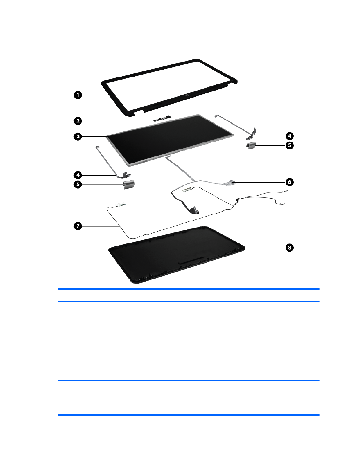
Display assembly components
Item Description Spare part number
(1) Display bezel 637188-001
(2) Webcam module 637197-001
(3) 39.6-cm (15.6-in) high-definition, BrightView LED display panel 647623-001
(4) Display bracket (with hinges) 637191-001
(5) Display hinge covers 641142-001
(6) Display cable (included in the Display Cable Kit) 641136-001
(7) Wireless antenna (includes wireless antenna transceivers and cable) 637185-001
(8) Display back cover (includes logo):
For use in Ocean Drive computer models 637186-001
●
For use in Sonoma Red computer models 641284-001
●
Display assembly components
27
Page 36

Item Description Spare part number
For use in Luminous Rose computer models 641286-001
●
For use in Charcoal Grey computer models 641288-001
●
For use in Pewter computer models 641290-001
●
For use in Pacific Blue computer models 641292-001
●
For use in Pearl Pink computer models 641294-001
●
For use in Sweet Purple computer models 641296-001
●
For use in Butter Gold computer models 641298-001
●
28 Chapter 3 Illustrated parts catalog
Page 37
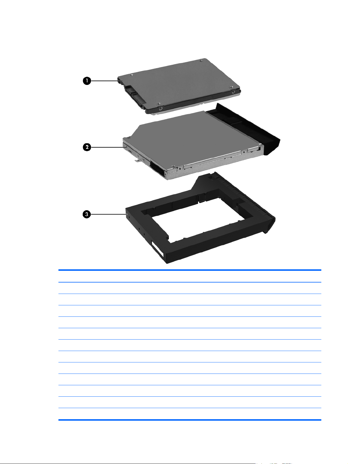
Mass storage devices
Item Description Spare part number
(1) Hard drive
Supports the following 9.5 mm, 6.3 cm (2.5 in) SATA hard drives:
Supports the following 7 mm, 6.3 cm (2.5 in) SATA hard drives:
Hard Drive Hardware Kit (not illustrated, includes bracket) 639444-001
(2) Optical drive (12.7 mm, SATA, fixed, includes bezel and bracket)
750 GB, 5400 rpm 644351-001
●
640 GB, 5400 rpm 637312-001
●
500 GB, 7200 rpm 644685-001
●
320 GB, 5400 rpm 645086-001
●
320 GB, 7200 rpm 645089-001
●
250 GB, 7200 rpm 645091-001
●
DVD±RW and CD-RW SuperMulti Double-Layer Combo Drive 659997-001
●
Mass storage devices
29
Page 38

Item Description Spare part number
(3) Optical Drive protective insert 659621-001
Blu-ray Disc ROM with DVD±R/RW SuperMulti Double-Layer Drive 659996-001
●
30 Chapter 3 Illustrated parts catalog
Page 39

Miscellaneous parts
Description Spare part number
AC adapters
65 W AC adapter 609939-001
●
90 W AC adapter 609940-001
●
65 W AC adapter (EM) 609948-001
●
90 W AC adapter (EM) 609947-001
●
Power cord, AC, 3 wire, black, 1.83-m
For use in North America 490371-001
●
For use in Australia 490371-011
●
For use in Europe 490371-021
●
For use in the United Kingdom and Singapore 490371-031
●
For use in Italy 490371-061
●
For use in Switzerland 490371-111
●
For use in Denmark 490371-081
●
For use in Thailand 490371-201
●
For use in Japan 490371-291
●
For use in the People's Republic of China 490371-AA1
●
For use in Taiwan 490371-AB1
●
For use in South Korea 490371-AD1
●
For use in South Africa 490371-AR1
●
For use in Israel 490371-BB1
●
For use in India 490371-D61
●
Bluetooth cable 602822-001
Bluetooth module 537921-001
Cable Kit (includes optical drive cable, hard drive cable, and TouchPad cable) 641139-001
Drive activity light board 640215-001
Thermal pad 634433-001
Miscellaneous parts
31
Page 40

Description Spare part number
TouchPad LED board 647622-001
Screw kit
Phillips 2.5×3.0 screw
●
Phillips 2.5×5 nylon screw
●
Phillips 3.0×2.0 screw
●
Phillips 2.5×6.5 screw
●
Phillips 2.5×10.3 screw
●
Phillips 4.0×2.5 screw
●
637194-001
32 Chapter 3 Illustrated parts catalog
Page 41

Sequential part number listing
Spare part number Description
490371-001 Power cord, AC, 3 wire, black, 1.83 m for use in North America
490371-011 Power cord, AC, 3 wire, black, 1.83 m for use in Australia
490371-021 Power cord, AC, 3 wire, black, 1.83 m for use in Europe
490371-031 Power cord, AC, 3 wire, black, 1.83 m for use in the United Kingdom and Singapore
490371-061 Power cord, AC, 3 wire, black, 1.83 m for use in Italy
490371-081 Power cord, AC, 3 wire, black, 1.83 m for use in Denmark
490371-111 Power cord, AC, 3 wire, black, 1.83 m for use in Switzerland
490371-201 Power cord, AC, 3 wire, black, 1.83 m for use in Thailand
490371-291 Power cord, AC, 3 wire, black, 1.83 m for use in Japan
490371-AA1 Power cord, AC, 3 wire, black, 1.83 m for use in the People's Republic of China
490371-AB1 Power cord, AC, 3 wire, black, 1.83 m for use in Taiwan
490371-AD1 Power cord, AC, 3 wire, black, 1.83 m for use in Korea
490371-AR1 Power cord, AC, 3 wire, black, 1.83 m for use in South Africa
490371-BB1 Power cord, AC, 3 wire, black, 1.83 m for use in Israel
490371-D61 Power cord, AC, 3 wire, black, 1.83 m for use in India
537921-001 Bluetooth module
580101-002 Atheros AR9285 802.11a/b/g/n 2x2 WiFi adapter
593127-001 Atheros AR9285 802.11b/g/n WiFi + Bluetooth Adapter
593530-001 Intel Centrino Wireless-N 1000 (802.11b/g/n)
593553–001 Battery, 6-cell, 2.20 Ah, 47 Wh
593554-001 Battery, 6-cell, 2.55 Ah, 55 Wh
593836-001 Broadcom 4313AGN 802.11a/b/g/draft-n WiFi Adapter
600370-001 Broadcom 4313 802.11b/g/n 1x1 WiFi and 2070 Bluetooth 2.1+EDR Combo adapter
(BT3.0+HS ready)
602822-001 Bluetooth cable
602993-001 Realtek 8188BC8 802.11a/b/g/n 2x2 WiFi and Bluetooth 3.0+HS Combo Adapter
605560-005 Atheros 9285G 802.11b/g/n 1x1 WiFi Adapter
609939-001 65 W AC adapter
609940-001 90 W AC adapter
609947-001 90 W AC adapter (EM)
609948-001 65 W AC adapter (EM)
Sequential part number listing
33
Page 42

Spare part number Description
616333-001 V140 processor (2.3 GHz, 512 KB L2 cache, 1066 MHz, 3.2 GT/s), SC 25 W
616343-001 Athlon II P340 processor (2.2 GHz, 1 MB L2 cache, 1066 MHz, 3.2 GT/s), Dual 25 W
616345-001 AMD Phenom II N850 processor (2.2 GHz, 1.5 MB L2 cache, 1333 MHz, 3.6 GT/s), Triple 35
W
621565-001 2 GB memory module, 10600 1333 MHz shared
621569-001 4 GB memory module, 10600 1333 MHz shared
625823-001 Intel Core i3-380M processor (2.53 GHz, 3 MB L3 cache), Dual 35 W
625831-001 Intel Pentium P6200 processor (2.13 GHz, 3 MB L3 cache), Dual 35 W
630703-001 Ralink 5390GN 802.11b/g/n 1x1 WiFi Adapter
630705-001 Ralink 5390BC8 802.11b/g/n 1x1 WiFi and Bluetooth 3.0+HS Combo Adapter
631252-001 Intel Core i7-2620M processor (2.7 GHz, SC turbo up to 3.40 GHz, 4 MB L3 cache), Dual 35
W
631253-001 Intel Core i5-2520M processor (2.5 GHz, SC turbo up to 3.2 GHz, 3 MB L3 cache), Dual 35 W
631255-001 Intel Core i5-2540M processor (2.6 GHz, SC turbo up to 3.3 GHz, 3 MB L3 cache), Dual 35 W
631956-001 Intel Centrino Wireless-N 1030 + Bluetooth (802.11b/g/n)
634433-001 Thermal pad
634687-001 AMD Phenom II P650 processor (2.6 GHz, 2 MB L2 cache, 1066 MHz, 3.6 GT/s), Dual 25 W
634688-001 AMD Phenom II P860 processor (2.0 GHz, 1.5 MB L2 cache, 1066 MHz, 3.6 GT/s), Triple 25
W
634689-001 AMD Phenom II P960 processor (1.8 GHz, 2 MB L2 cache, 1066 MHz, 3.6 GT/s), Quad 25 W
634691-001 Turion II P560 processor (2.5 GHz, 2 MB L2 cache, 1066 MHz, 3.6 GT/s), Dual 25 W
634692-001 Intel Core i3-390M processor (2.66 GHz, 3 MB L3 cache), Dual 35 W
634693-001 Intel Core i5-480M processor (2.66 GHz, SC turbo up to 2.93 GHz, 3 MB L3 cache), Dual 35
W
635494-001 AMD Phenom II N660 processor (3.0 GHz, 2 MB L2 cache, 1333 MHz, 3.6 GT/s), Dual 35 W
635495-001 AMD Phenom II N870 processor (2.3 GHz, 1.5 MB L2 cache, 1333 MHz, 3.6 GT/s), Triple 35
W
635496-001 AMD Phenom II N970 processor (2.2 GHz, 2 MB L2 cache, 1333 MHz, 3.6 GT/s), Quad 35
W
635500-001 Intel Pentium P6300 processor (2.26 GHz, 3 MB L3 cache), Dual 35 W
636370-001 System board (includes replacement thermal material) for use in Intel HM55 UMA computer
models
636371-001 System board (includes replacement thermal material) for use in Intel HM55 6470 discrete, 512
MB, computer models
636372-001 System board (includes replacement thermal material) for use in Intel HM55 6470 discrete, 1 GB,
computer models
34 Chapter 3 Illustrated parts catalog
Page 43

Spare part number Description
636373-001 System board (includes replacement thermal material) use in Intel HM65 UMA computer models
636374-001 System board (includes replacement thermal material) for use in Intel HM65 discrete, 512 M,
computer models
636375-001 System board (includes replacement thermal material) for use in Intel HM65 6470 discrete, 1 GB,
computer models
636376-001 Keyboard, black (includes keyboard cable) for use in the United States, Black
636376-031 Keyboard, black (includes keyboard cable) for use in the United Kingdom
636376-041 Keyboard, black (includes keyboard cable) for use in Germany
636376-051 Keyboard, black (includes keyboard cable) for use in France
636376-061 Keyboard, black (includes keyboard cable) for use in Italy
636376-071 Keyboard, black (includes keyboard cable) for use in Spain
636376-121 Keyboard, black (includes keyboard cable) for use in French Canada
636376-131 Keyboard, black (includes keyboard cable) for use in Portugal
636376-141 Keyboard, black (includes keyboard cable) for use in Turkey
636376-171 Keyboard, black (includes keyboard cable) for use in Saudi Arabia
636376-211 Keyboard, black (includes keyboard cable) for use in Hungary
636376-221 Keyboard, black (includes keyboard cable) for use in Czechoslovakia
636376-251 Keyboard, black (includes keyboard cable) for use in Russia
636376-281 Keyboard, black (includes keyboard cable) for use in Thailand
636376-291 Keyboard, black (includes keyboard cable) for use in Japan
636376-A41 Keyboard, black (includes keyboard cable) for use in Europe
636376-AB1 Keyboard, black (includes keyboard cable) for use in Taiwan
636376-AD1 Keyboard, black (includes keyboard cable) for use in Korea
636376-B31 Keyboard, black (includes keyboard cable) for international use
636376-BA1 Keyboard, black (includes keyboard cable) for use in the Adriatics
636376-BB1 Keyboard, black (includes keyboard cable) for use in Israel
636376-BG1 Keyboard, black (includes keyboard cable) for use in Switzerland
636376-D61 Keyboard, black (includes keyboard cable) for use in India
636376-DH1 Keyboard, black (includes keyboard cable) for use in the Netherlands
636376-DJ1 Keyboard, black (includes keyboard cable) for use in Greece
636378-001 39.6 cm (15.6 in) HD LED BrightView (1366×768) display assembly for use in Ocean Drive
computer models
636634-001 V160 processor (2.4 GHz, 512 KB L2 cache, 1066 MHz, 3.2 GT/s), SC 25 W
636635-001 Athlon II P360 processor (2.3 GHz, 1 MB L2 cache, 1066 MHz, 3.6 GT/s), Dual 25 W
Sequential part number listing
35
Page 44

Spare part number Description
637185-001 Wireless antenna (includes wireless antenna transceivers and cable)
637186-001 Display back cover (includes logo) for use in Ocean Drive computer models
637187-001 Base enclosure
637188-001 Display bezel
637189-001 Heat sink assembly (includes replacement thermal material) for use in Intel HM55 UMA computer
models
637190-001 Heat sink assembly (includes replacement thermal material) for use in Intel HM55 discrete
computer models
637191-001 Display bracket (with hinges)
637192-001 Plastics Kit (includes service door)
637193-001 RTC battery
637194-001 Screw Kit
637196-001 Top cover for use in Ocean Drive computer models
637197-001 Webcam module
637312-001 640 GB, 5400 rpm 9.5 mm, 6.35 cm (2.5 in) SATA hard drive
638037-001 Intel Core i3-2310M processor (2.1 GHz, 3 MB L3 cache) Dual 35 W
638039-001 Intel Core i5-2410M processor (2.3 GHz, SC turbo up to 2.9 GHz, 3 MB L3 cache), Dual 35 W
638854-001 System board (includes replacement thermal material) for use in AMD 6470 discrete, 512 MB
computer models
638855-001 System board (includes replacement thermal material) for use in AMD 6470 discrete, 1 GB
computer models
638856-001 System board (includes replacement thermal material) for use in AMD UMA computer models
639444-001 Hard Drive Hardware Kit (includes bracket)
639455-001 Rubber Kit (includes rubber feet)
639460-001 Heat sink fan
639462-001 Heat sink assembly (includes replacement thermal material) for use in AMD discrete computer
models
639463-001 Heat sink assembly (includes replacement thermal material) for use in AMD UMA computer
models
640215-001 Drive activity light board
640926-001 Realtek 8188GN 802.11b/g/n 1x1 WiFi Adapter
641136-001 Display cable (included in the Display Cable Kit)
641137-001 Power connector (includes cable)
641139-001 Cable Kit (includes optical drive cable, hard drive cable, and TouchPad cable)
36 Chapter 3 Illustrated parts catalog
Page 45

Spare part number Description
641140-001 Heat sink assembly (includes replacement thermal material) for use in Intel HM65 UMA computer
models
641141-001 Heat sink assembly (includes replacement thermal material) for use in Intel HM65 discrete
computer models
641142-001 Display hinge covers
641143-001 TouchPad button board (includes bracket and cable)
641144-001 Power button board (includes cable)
641145-001 USB board (includes cable)
641284-001 Display back cover (includes logo) for use in Sonoma Red computer models
641285-001 Top cover (includes TouchPad board) for use in Sonoma Red computer models
641286-001 Display back cover (includes logo) for use in Luminous Rose computer models
641287-001 Top cover (includes TouchPad board) for use in Luminous Rose computer models
641288-001 Display back cover (includes logo) for use in Charcoal Grey computer models
641289-001 Top cover (includes TouchPad board) for use in Charcoal Grey computer models
641290-001 Display back cover (includes logo) for use in Pewter computer models
641291-001 Top cover (includes TouchPad board) for use in Pewter computer models
641292-001 Display back cover (includes logo) for use in Pacific Blue computer models
641293-001 Top cover (includes TouchPad board) for use in Pacific Blue computer models
641294-001 Display back cover (includes logo) for use in Pearl Pink computer models
641295-001 Top cover (includes TouchPad board) for use in Pearl Pink computer models
641296-001 Display back cover (includes logo) for use in Sweet Purple computer models
641297-001 Top cover (includes TouchPad board) for use in Sweet Purple computer models
641298-001 Display back cover (includes logo) for use in Butter Gold computer models
641299-001 Top cover (includes TouchPad board) for use in Butter Gold computer models
641396-001 Speaker assembly (includes cable)
644351-001 750 GB, 5400 rpm 9.5 mm, 6.35 cm (2.5 in) SATA hard drive
644685-001 500 GB, 7200 rpm 9.5 mm, 6.35 cm (2.5 in) SATA hard drive
645086-001 320 GB, 5400 rpm 9.5 mm, 6.35 cm (2.5 in) SATA hard drive
645089-001 320 GB, 7200 rpm, 7.0 mm, 6.35 cm (2.5 in) SATA hard drive
645091-001 250 GB, 7200 rpm, 7.0 mm, 6.35 cm (2.5 in) SATA hard drive
645521-001 39.6 cm (15.6 in) HD LED BrightView (1366×768) display assembly for use in Sonoma Red
computer models
645522-001 39.6 cm (15.6 in) HD LED BrightView (1366×768) display assembly for use in Luminous Rose
computer models
Sequential part number listing
37
Page 46

Spare part number Description
645523-001 39.6 cm (15.6 in) HD LED BrightView (1366×768) display assembly for use in Charcoal Grey
computer models
645524-001 39.6 cm (15.6 in) HD LED BrightView (1366×768) display assembly for use in Pewter computer
models
645525-001 39.6 cm (15.6 in) HD LED BrightView (1366×768) display assembly for use in Pacific Blue
computer models
645526-001 39.6 cm (15.6 in) HD LED BrightView (1366×768) display assembly for use in Pearl Pink
computer models
645527-001 39.6 cm (15.6 in) HD LED BrightView (1366×768) display assembly for use in Sweet Purple
computer models
645528-001 39.6 cm (15.6 in) HD LED BrightView (1366×768) display assembly for use in Butter Gold
computer models
645529-001 System board (includes replacement thermal material) for use in AMD E-350 UMA computer
models
645893-001 Keyboard for use in the United States, Pink
645893-031 Keyboard for use in the United Kingdom, Pink
645893-041 Keyboard for use in Germany, Pink
645893-051 Keyboard for use in France, Pink
645893-061 Keyboard for use in Italy, Pink
645893-071 Keyboard for use in Spain, Pink
645893-121 Keyboard for use in French Canada, Pink
645893-131 Keyboard for use in Portugal, Pink
645893-141 Keyboard for use in Turkey, Pink
645893-171 Keyboard for use in Saudi Arabia, Pink
645893-211 Keyboard for use in Hungary, Pink
645893-221 Keyboard for use in Czechoslovakia, Pink
645893-251 Keyboard for use in Russia, Pink
645893-261 Keyboard for use in Bulgaria, Pink
645893-281 Keyboard for use in Thailand, Pink
645893-291 Keyboard for use in Japan, Pink
645893-A41 Keyboard for use in Europe, Pink
645893-AB1 Keyboard for use in Taiwan, Pink
645893-AD1 Keyboard for use in Korea, Pink
645893-B31 Keyboard for international use, Pink
645893-BA1 Keyboard for use in the Adriatics, Pink
38 Chapter 3 Illustrated parts catalog
Page 47

Spare part number Description
645893-BB1 Keyboard for use in Israel, Pink
645893-BG1 Keyboard for use in Switzerland, Pink
645893-D61 Keyboard for use in India, Pink
645893-DH1 Keyboard for use in the Netherlands, Pink
645893-DJ1 Keyboard for use in Greece, Pink
647622-001 TouchPad LED board
647623-001 39.6-cm (15.6-in) high-definition, BrightView LED display panel
647626-001 System board (includes replacement thermal material) for use in AMD 880MD 6470 discrete,
512 MB, BACO computer models
647627-001 System board (includes replacement thermal material) for use in AMD 880MD 6470 discrete, 1
GB, BACO computer models
649948-001 System board (includes replacement thermal material) for use in AMD A60M UMA computer
models
649949-001 System board (includes replacement thermal material) for use in AMD A60M HD6470 discrete,
512 MB computer models
649950-001 System board (includes replacement thermal material) for use in AMD A60M HD6470 discrete, 1
GB computer models
649952-001 System board (includes replacement thermal material) for use in AMD BGA UMA computer
models
649953-001 System board (includes replacement thermal material) for use in AMD A60M UMA computer
models
649954-001 System board (includes replacement thermal material) for use in AMD UMA A60M computer
models
650198-001 System board (includes replacement thermal material) for use in Intel HM65 6470 discrete, 512
MB, BACO, computer models
650199-001 System board (includes replacement thermal material) for use in Intel HM65 6470 discrete, 1 GB
BACO, computer models
653338-001 Intel Pentium B950 processor (2.1 GHz, 2 MB L3 cache), Dual 35 W
653339-001 Intel Core i3-2330M processor (2.2 GHz, 3 MB L3 cache) Dual 35 W
653340-001 Intel Core i3-2350M processor (2.3 GHz, 3 MB L3 cache) Dual 35 W
653341-001 Intel Core i5-2430M processor (2.4 GHz, SC turbo up to 3.0GHz, 3 MB L3 cache), Dual 35 W
653348-001 AMD A Series APU A4-3300M (2.5 GHz/1.9 GHz, 2 MB L2 cache), Dual 35 W
653349-001 AMD A Series APU A6-3400M (2.3 GHz/1.4 GHz, 4 MB L2 cache), Quad 35 W
653350-001 AMD A Series APU A8-3500M (2.4 GHz/1.5 GHz, 4 MB L2 cache), Quad 35 W
653351-001 AMD A Series APU E2-3000M (2.4 GHz/1.8 GHz, 1 MB L2 cache), Dual 35 W
654117-001 System board (includes replacement thermal material) for use in Intel HM55 i3–370M discrete,
512 MB/1 GB computer models
Sequential part number listing
39
Page 48

Spare part number Description
654118-001 System board (includes replacement thermal material) for use in Intel HM55 i3–370M UMA
computer models
654119-001 Heat sink assembly (includes replacement thermal material) for use in Intel BGA discrete computer
models
654120-001 Heat sink assembly (includes replacement thermal material) for use in Intel BGA UMA computer
models
655795-001 Atheros 9485GN 802.11b/g/n 1x1 WiFi and 3012 Bluetooth 4.0 Combo Adapter
657325-001 Broadcom 4313GN 802.11b/g/n 1x1 WiFi and 20702 Bluetooth 4.0 Combo Adapter
659621-001 Optical Drive protective insert
659871-001 System board with integrated AMD E450 processor
659996-001 Blu-ray Disc ROM and DVD±R/RW SuperMulti Double-Layer Drive
659997-001 DVD±RW and CD-RW SuperMulti Double-Layer Combo Drive
664662-001 Intel Pentium B960 processor (2.2 GHz, 2 MB L3 cache), Dual 35 W
40 Chapter 3 Illustrated parts catalog
Page 49

4 Removal and replacement
procedures
Preliminary replacement requirements
Tools required
The following tools are needed to complete the removal and replacement procedures:
Flat-bladed screwdriver
●
Magnetic screwdriver
●
Phillips P0 and P1 screwdrivers
●
Service considerations
Before disassembly or assembly procedures, review and adhere to all service considerations.
NOTE: As you remove each subassembly from the computer, place the subassembly (and all
accompanying screws) away from the work area to prevent damage.
Plastic parts
Using excessive force during disassembly and reassembly can damage plastic parts. Use care when
handling the plastic parts. Apply pressure only at the points designated in the maintenance instructions.
Preliminary replacement requirements
41
Page 50

Cables and connectors
CAUTION: When servicing the computer, be sure that cables are placed in their proper locations
during the reassembly process. Improper cable placement can damage the computer.
Cables must be handled with extreme care to avoid damage. Apply only the tension required to unseat
or seat the cables during removal and insertion. Handle cables by the connector whenever possible. In
all cases, avoid bending, twisting, or tearing cables. Be sure that cables are routed in such a way that
they cannot be caught or snagged by parts being removed or replaced. Handle flex cables with
extreme care; these cables tear easily.
Drive handling
CAUTION: Drives are fragile components that must be handled with care. To prevent damage to the
computer, damage to a drive, or loss of information, observe these precautions:
Before removing or inserting a hard drive, shut down the computer. If you are unsure whether the
computer is off or in Hibernation, turn the computer on, and then shut it down through the operating
system.
Before handling a drive, be sure that you are discharged of static electricity. While handling a drive,
avoid touching the connector.
Before removing a diskette drive or optical drive, be sure that a diskette or disc is not in the drive and
be sure that the optical drive tray is closed.
Handle drives on surfaces covered with at least one inch of shock-proof foam.
Avoid dropping drives from any height onto any surface.
After removing a hard drive, an optical drive, or a diskette drive, place it in a static-proof bag.
Avoid exposing a hard drive to products that have magnetic fields, such as monitors or speakers.
Avoid exposing a drive to temperature extremes or liquids.
If a drive must be mailed, place the drive in a bubble pack mailer or other suitable form of protective
packaging and label the package “FRAGILE.”
42 Chapter 4 Removal and replacement procedures
Page 51

Grounding guidelines
Electrostatic discharge damage
Electronic components are sensitive to electrostatic discharge (ESD). Circuitry design and structure
determine the degree of sensitivity. Networks built into many integrated circuits provide some
protection, but in many cases, ESD contains enough power to alter device parameters or melt
silicon junctions.
A discharge of static electricity from a finger or other conductor can destroy static-sensitive devices or
microcircuitry. Even if the spark is neither felt nor heard, damage might have occurred.
An electronic device exposed to ESD might not be affected at all and can work perfectly throughout a
normal cycle. Or the device might function normally for a while, then degrade in the internal layers,
reducing its life expectancy.
CAUTION: To prevent damage to the computer when removing or installing internal components,
observe these precautions:
Keep components in their electrostatic-safe containers until you are ready to install them.
Use nonmagnetic tools.
Before touching an electronic component, discharge static electricity by using the guidelines described
in this section.
Avoid touching pins, leads, and circuitry. Handle electronic components as little as possible.
If you remove a component, place it in an electrostatic-safe container.
The following table shows how humidity affects the electrostatic voltage levels generated by different
activities.
CAUTION: A product can be degraded by as little as 700 V.
Typical electrostatic voltage levels
Relative humidity
Event 10% 40% 55%
Walking across carpet 35,000 V 15,000 V 7,500 V
Walking across vinyl floor 12,000 V 5,000 V 3,000 V
Motions of bench worker 6,000 V 800 V 400 V
Removing DIPS from plastic tube 2,000 V 700 V 400 V
Removing DIPS from vinyl tray 11,500 V 4,000 V 2,000 V
Removing DIPS from Styrofoam 14,500 V 5,000 V 3,500 V
Removing bubble pack from PCB 26,500 V 20,000 V 7,000 V
Packing PCBs in foam-lined box 21,000 V 11,000 V 5,000 V
Preliminary replacement requirements
43
Page 52

Packaging and transporting guidelines
Follow these grounding guidelines when packaging and transporting equipment:
To avoid hand contact, transport products in static-safe tubes, bags, or boxes.
●
Protect ESD-sensitive parts and assemblies with conductive or approved containers or packaging.
●
Keep ESD-sensitive parts in their containers until the parts arrive at static-free workstations.
●
Place items on a grounded surface before removing items from their containers.
●
Always be properly grounded when touching a component or assembly.
●
Store reusable ESD-sensitive parts from assemblies in protective packaging or nonconductive
●
foam.
Use transporters and conveyors made of antistatic belts and roller bushings. Be sure that
●
mechanized equipment used for moving materials is wired to ground and that proper materials
are selected to avoid static charging. When grounding is not possible, use an ionizer to dissipate
electric charges.
Workstation guidelines
Follow these grounding workstation guidelines:
Cover the workstation with approved static-shielding material.
●
Use a wrist strap connected to a properly grounded work surface and use properly grounded tools
●
and equipment.
Use conductive field service tools, such as cutters, screwdrivers, and vacuums.
●
When fixtures must directly contact dissipative surfaces, use fixtures made only of static-safe
●
materials.
Keep the work area free of nonconductive materials, such as ordinary plastic assembly aids and
●
Styrofoam.
Handle ESD-sensitive components, parts, and assemblies by the case or PCM laminate. Handle
●
these items only at static-free workstations.
Avoid contact with pins, leads, or circuitry.
●
Turn off power and input signals before inserting or removing connectors or test equipment.
●
44 Chapter 4 Removal and replacement procedures
Page 53

Equipment guidelines
Grounding equipment must include either a wrist strap or a foot strap at a grounded workstation.
When seated, wear a wrist strap connected to a grounded system. Wrist straps are flexible straps
●
with a minimum of one megohm ±10% resistance in the ground cords. To provide proper ground,
wear a strap snugly against the skin at all times. On grounded mats with banana-plug connectors,
use alligator clips to connect a wrist strap.
When standing, use foot straps and a grounded floor mat. Foot straps (heel, toe, or boot straps)
●
can be used at standing workstations and are compatible with most types of shoes or boots. On
conductive floors or dissipative floor mats, use foot straps on both feet with a minimum of one
megohm resistance between the operator and ground. To be effective, the conductive strips must
be worn in contact with the skin.
The following grounding equipment is recommended to prevent electrostatic damage:
Antistatic tape
●
Antistatic smocks, aprons, and sleeve protectors
●
Conductive bins and other assembly or soldering aids
●
Nonconductive foam
●
Conductive tabletop workstations with ground cords of one megohm resistance
●
Static-dissipative tables or floor mats with hard ties to the ground
●
Field service kits
●
Static awareness labels
●
Material-handling packages
●
Nonconductive plastic bags, tubes, or boxes
●
Metal tote boxes
●
Electrostatic voltage levels and protective materials
●
The following table lists the shielding protection provided by antistatic bags and floor mats.
Material Use Voltage protection level
Antistatic plastic Bags 1,500 V
Carbon-loaded plastic Floor mats 7,500 V
Metallized laminate Floor mats 5,000 V
Preliminary replacement requirements
45
Page 54
Component replacement procedures
This chapter provides removal and replacement procedures.
There are as many as 78 screws, in 8 different sizes, that must be removed, replaced, or loosened
when servicing the computer. Make special note of each screw size and location during removal and
replacement.
Serial number
The serial number label, located in the battery bay of the computer, provides important information that
you may need when contacting technical support.
(1) Product name (4) Warranty period
(2) Serial number (5) Model description
(3) Product number
46 Chapter 4 Removal and replacement procedures
Page 55
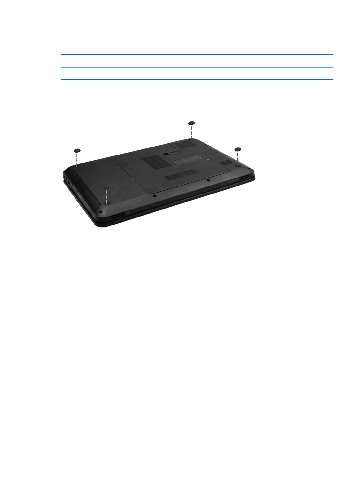
Computer feet
Description Spare part number
Rubber Feet Kit 639455-001
The computer feet are adhesive-backed rubber pads. The feet attach to the base enclosure in the
locations illustrated below.
Component replacement procedures
47
Page 56
Battery
Description Spare part number
6 cell, 2.20 Ah, 47 Wh 593553-001
6 cell, 2.55 Ah, 55 Wh 593554-001
Before disassembling the computer:
1. Shut down the computer. If you are unsure whether the computer is off or in Hibernation, turn on
the computer, and then shut it down through the operating system.
2. Disconnect all external devices connected to the computer.
3. Disconnect the power from the computer by first disconnecting the power cord from the AC outlet
and then disconnecting the AC adapter from the computer.
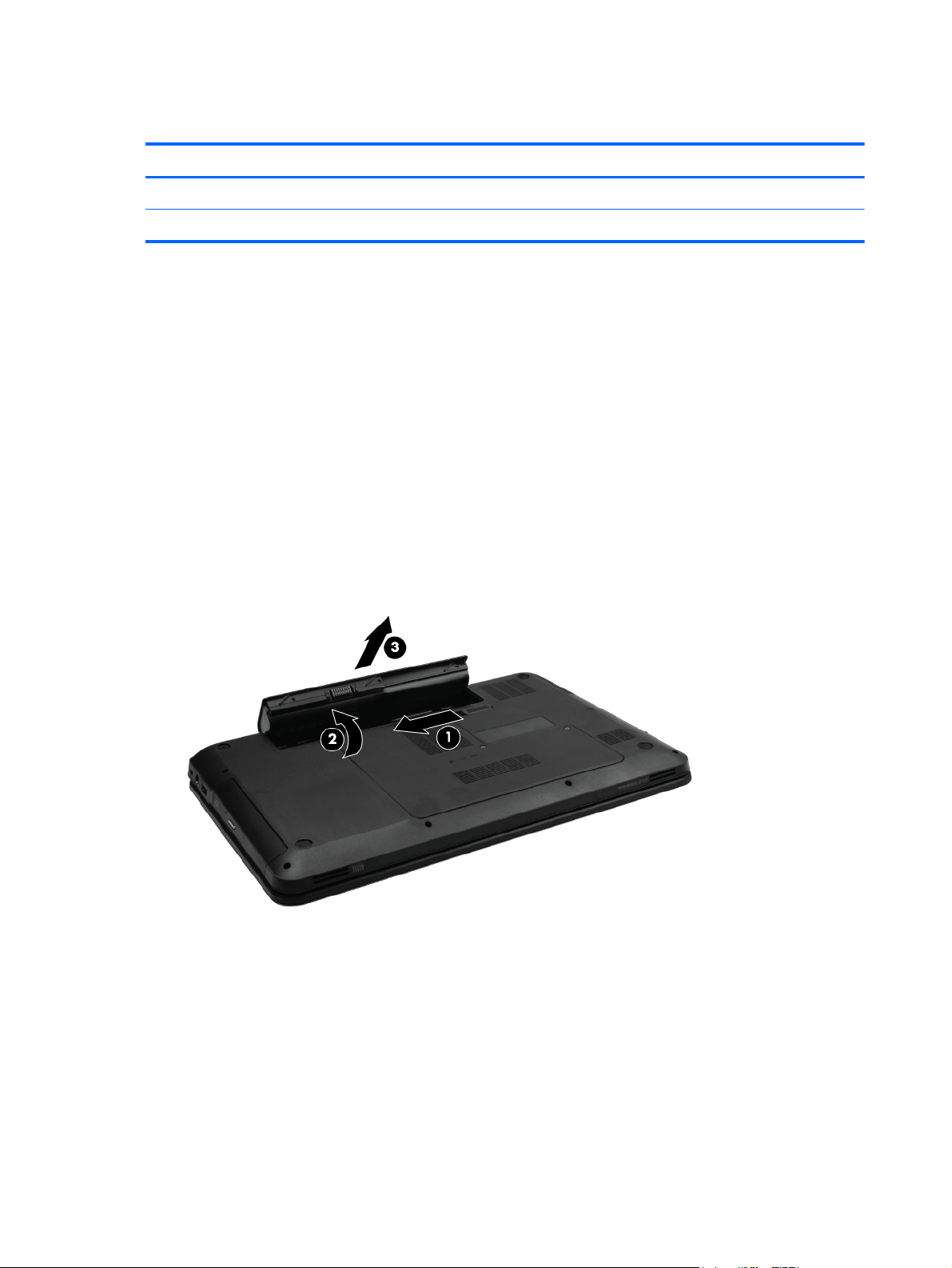
Remove the battery:
1. Position the computer upside down on a flat surface.
2. Slide the battery release latch (1) to release the battery.
3. Pivot the battery (2) upward and lift it out of the computer (3).
To insert the battery, insert the rear edge of the battery into the battery bay and pivot the front edge
downward until the battery is seated. The battery release latch automatically locks the battery into
place.
48 Chapter 4 Removal and replacement procedures
Page 57

Service door
Description Spare part number
Plastics Kit (contains the service door) 637192-001
Before removing the service door, remove the battery (see Battery on page 48)
1. Position the computer upside down, with the front toward you.
2. Loosen the two Phillips 4.0×2.0 captive screws (1) that secure the service door to the computer.
3. Remove the service door (2).
Reverse this procedure to install the service door.
Component replacement procedures
49
Page 58

Hard drive
NOTE: The hard drive spare part kit includes a hard drive bracket and hard drive connector. The
hard drive bracket and hard drive connector, as well as the hard drive bracket screws, are also
available in the Hard Drive Hardware Kit.
Description Spare part number
Supports the following 9.50 mm, 6.35 cm (2.50 in) SATA hard drives:
750 GB, 5400 rpm 644351-001
640 GB, 5400 rpm 637312-001
500 GB, 7200 rpm 644685-001
320 GB, 5400 rpm 645086–001
Supports the following 7.00 mm, 6.35 cm (2.50 in) SATA hard drives:
320 GB, 7200 rpm 645089-001
250 GB, 7200 rpm 645091-001
Hard Drive Hardware Kit (not illustrated, includes bracket) 639444-001
Before removing the hard drive, remove the following components:
1. Battery (see
2. Service door (see
Battery on page 48)
Service door on page 49)
50 Chapter 4 Removal and replacement procedures
Page 59
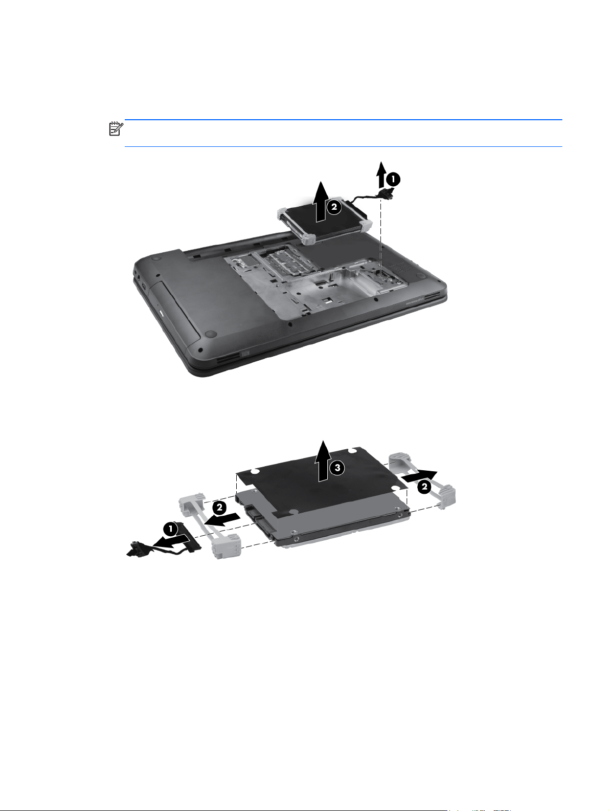
Remove the hard drive:
1. Disconnect the hard drive adapter cable from the system board (1) and then pull up on the tab
(2) to remove the drive from the hard drive bay.
NOTE: If the rubber hard drive bracket is wedged into the hard drive bay snugly, you may need
to gently pry up the hard drive using a thin nonconductive tool.
2. Disconnect the hard drive adapter (1). Then remove the hard drive bumpers (2), and the cover
(3).
Reverse this procedure to install the hard drive.
Component replacement procedures
51
Page 60

Optical drive
NOTE: The optical drive spare part kit includes an optical drive bezel and optical drive bracket.
Description Spare part number
DVD±RW and CD-RW SuperMulti Double-Layer Combo Drive 659997-001
Blu-ray Disc ROM and DVD±R/RW SuperMulti Double-Layer Drive 659996-001
Optical Drive protective insert 659621-001
Before removing the optical drive:
1. Battery (see
2. Service door (see
Battery on page 48)
Service door on page 49)
Remove the optical drive:
1. Remove the Phillips 3.0×2.5 screw (1) that secures the optical drive to the computer.
2. Insert a thin tool, such as a paper clip (2), into the release access slot next to the hard drive bay.
3. Grasp the bezel and slide the optical drive out of the computer (3).
4. To replace the optical drive bracket, position the optical drive with the optical drive bracket
toward you.
5. Remove the two Phillips 3.0×2.0 screws (1) that secure the optical drive bracket to the optical
drive.
52 Chapter 4 Removal and replacement procedures
Page 61

6. Remove the optical drive bracket (2).
7. To replace the optical drive bezel, disconnect it from the optical drive.
Reverse this procedure to reassemble and install the optical drive.
Component replacement procedures
53
Page 62

WLAN module
Description Spare part
Atheros 9285G 802.11b/g/n WiFi Adapter 580101-001
Atheros 9285G 802.11b/g/n 1x1 WiFi Adapter 605560-005
number
Broadcom 4313 802.11b/g/n 1x1 WiFi and 2070 Bluetooth 2.1+EDR Combo adapter (BT3.0+HS
ready)
Broadcom 4313AGN 802.11a/b/g/draft-n WiFi Adapter 593836-001
Intel Centrino Wireless-N 1030 + Bluetooth (802.11b/g/n) 631956-001
Intel Centrino Wireless-N 1000 (802.11 b/g/n) 593530-001
Ralink 5390GN 802.11b/g/n 1x1 WiFi Adapter 630703-001
Ralink 5390BC8 802.11b/g/n 1x1 WiFi and Bluetooth 3.0+HS Combo Adapter 630705-001
Realtek 8188GN 802.11b/g/n 1x1 WiFi Adapter 640926-001
Realtek 8188BC8 802.11a/b/g/n 2x2 WiFi and Bluetooth 3.0+HS Combo Adapter 602993-001
Atheros AR9002WB-1NGB 802.11b/g/n 1x1 WiFi and Bluetooth 2.1+EDR Combo Adapter 593127-001
Atheros 9485GN 802.11b/g/n 1x1 WiFi and 3012 Bluetooth 4.0 Combo Adapter 655795-001
Realtek RTL8188CE 802.11b/g/n 1x1 WiFi and Bluetooth 4.0 LE Combo Adapter 656119-001
600370-001
Before removing the WLAN module, remove the following components:
1. Battery (see
Battery on page 48)
2. Service door (see
Service door on page 49)
Remove the WLAN module:
1. Disconnect the main antenna cable (1) and the auxiliary antenna cable (2) from the wireless
module.
2. Remove the Phillips 3.0×2.0 screw (3) that secures the WLAN module to the computer. (The edge
of the module opposite the slot rises away from the computer.)
54 Chapter 4 Removal and replacement procedures
Page 63

3. Remove the WLAN module (4) by pulling it away from the slot at an angle.
CAUTION: To prevent an unresponsive system, replace the wireless module only with a wireless
module authorized for use in the computer by the governmental agency that regulates wireless
devices in your country or region. If you replace the module and then receive a warning message,
remove the module to restore computer functionality, and then contact technical support through
Help and Support.
NOTE: WLAN modules are designed with a notch (5) to prevent incorrect insertion into the
WLAN module slot.
Reverse this procedure to install a WLAN module.
Component replacement procedures
55
Page 64
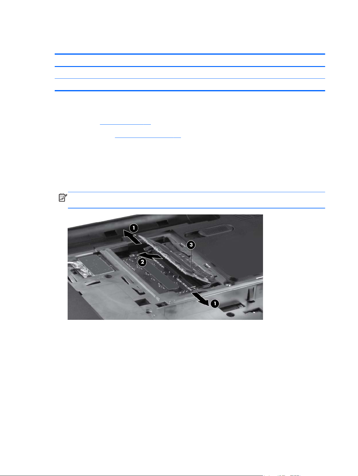
Memory module
Description Spare part number
4 GB PC3 10600 1333 MHz shared 621569-001
2 GB PC3 10600 1333 MHz shared 621565–001
Before removing the memory module, remove the following components:
1. Battery (see
2. Service door (see
Battery on page 48)
Service door on page 49)
Remove the memory module:
1. Spread the retaining tabs (1) on each side of the memory module slot to release the memory
module. (The edge of the module opposite the slot rises away from the computer.)
2. Remove the module (2) by pulling it away from the slot at an angle.
NOTE: Memory modules are designed with a notch (3) to prevent incorrect insertion into the
memory module slot.
Reverse this procedure to install a memory module.
56 Chapter 4 Removal and replacement procedures
Page 65

Keyboard
Description Spare part number
See
keyboards.
Before removing the keyboard, remove the following components:
Computer major components on page 19 for complete list of available
1. Battery (see
2. Service door (see
Battery on page 48)
Service door on page 49)
Remove the keyboard:
1. Remove the Phillips 5.0×2.5 screw that secures the keyboard to the computer.
Component replacement procedures
57
Page 66
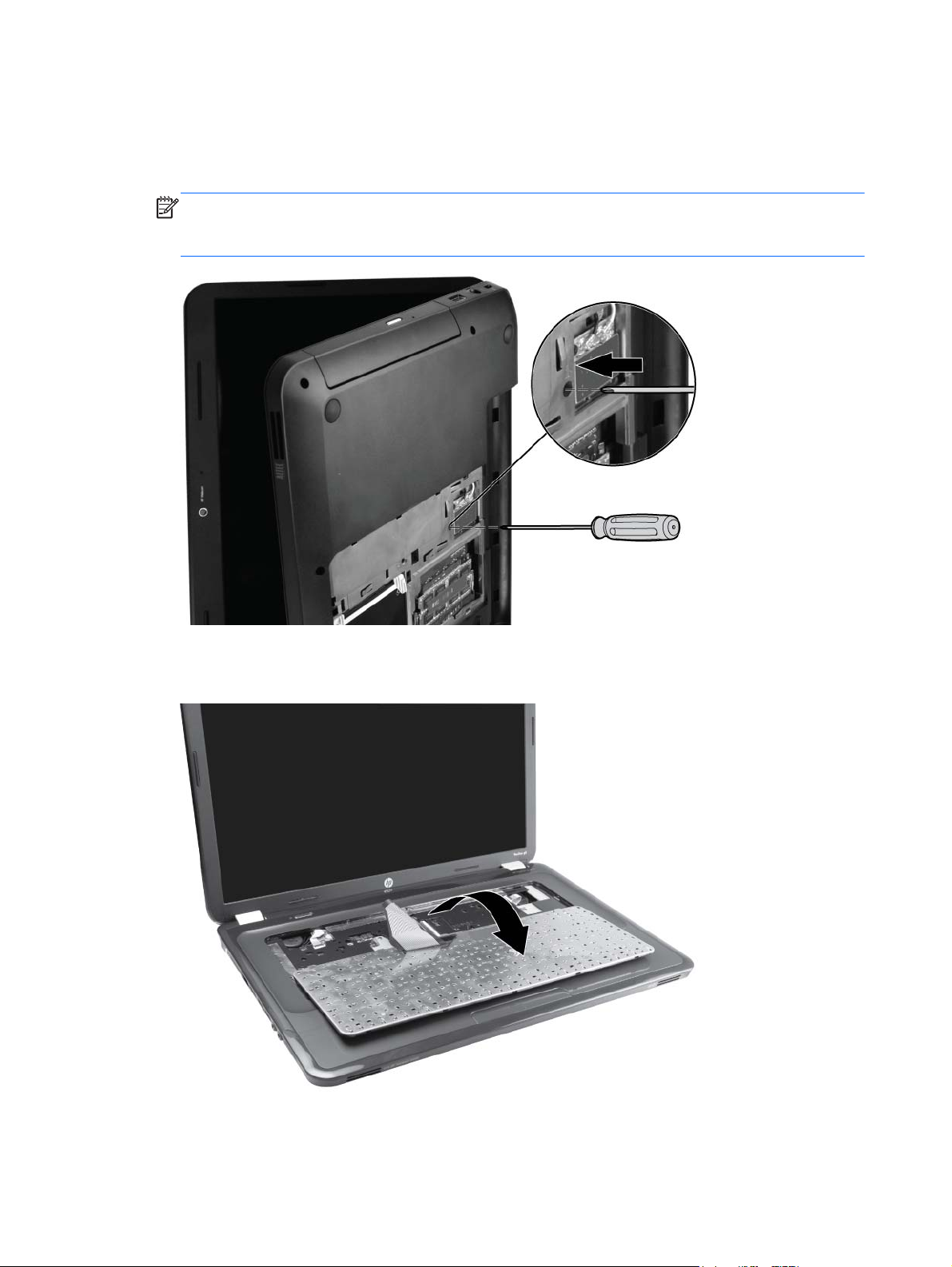
2. Open the display and stand the computer on its side. Insert a small screwdriver through the
keyboard access hole in the bottom of the computer. (The keyboard access hole is the same hole
from which the keyboard screw was removed.) Push firmly on the bottom of the keyboard until it is
disengaged.
NOTE: When the computer is standing on its side, the hard drive assembly may come out of its
bay still cabled to the computer. After disengaging the keyboard, reseat the hard drive assembly
as necessary prior to the next step.
3. Position the computer display-side up, with the front toward you, and open the display as far as
possible. Lift the rear edge of the keyboard and tilt the keyboard forward onto the palm rest.
58 Chapter 4 Removal and replacement procedures
Page 67
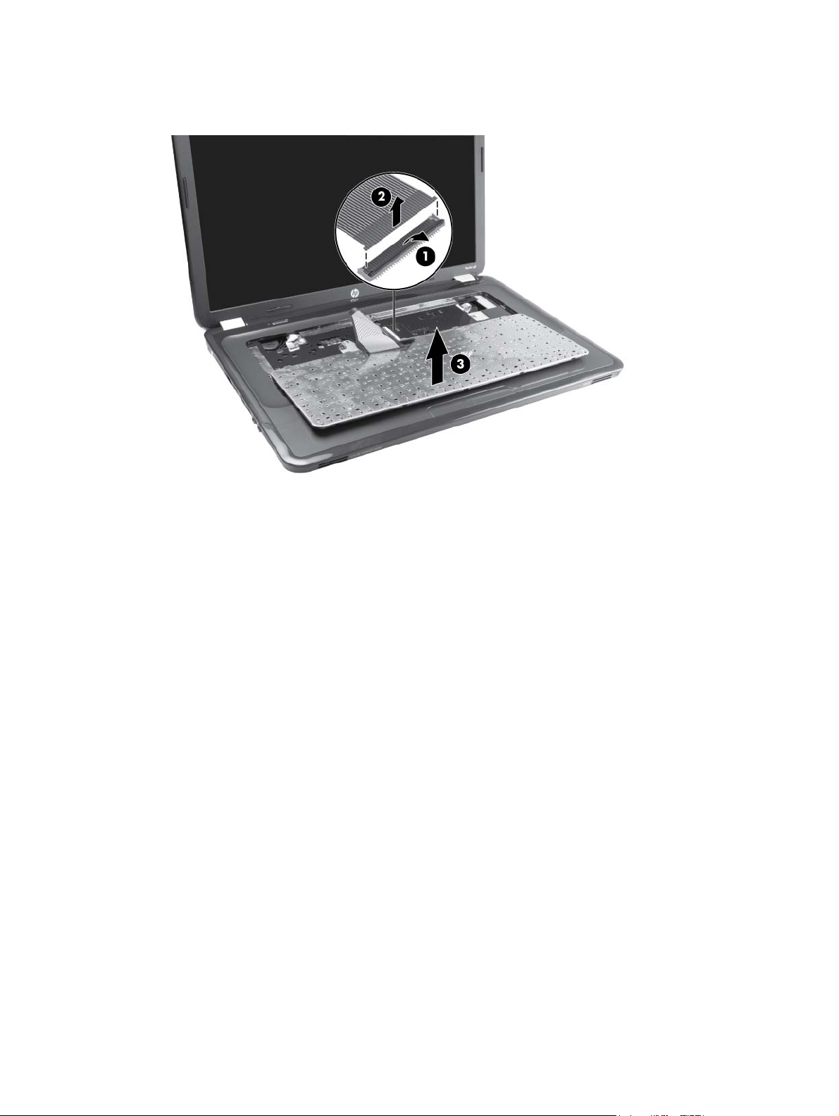
4. Release the zero insertion force (ZIF) connector (1) to which the keyboard cable is attached, and
then disconnect the keyboard cable (2). Remove the keyboard (3).
Reverse this procedure to install the keyboard.
Component replacement procedures
59
Page 68

Top cover
Description Spare part number
For use in Ocean Drive computer models 637196-001
For use in Luminous Rose computer models 641287-001
For use in Sweet Purple computer models 641297-001
For use in Butter Gold computer models 641299-001
For use in Pewter computer models 641291-001
For use in Charcoal Grey computer models 641289-001
For use in Sonoma Red computer models 641285-001
For use in Pacific Blue computer models 641293-001
For use in Pearl Pink computer models 641295-001
Before removing the top cover, remove the following components:
1. Battery (see
2. Service door (see
3. Hard drive (see
4. Optical drive (see
5. WLAN module (see
6. Memory module (see
7. Keyboard (see
Battery on page 48)
Service door on page 49)
Hard drive on page 50).
Optical drive on page 52).
WLAN module on page 54).
Memory module on page 56).
Keyboard on page 57).
Remove the top cover:
1. Position the computer display-side up, with the front toward you, and open the display as far as
possible.
60 Chapter 4 Removal and replacement procedures
Page 69
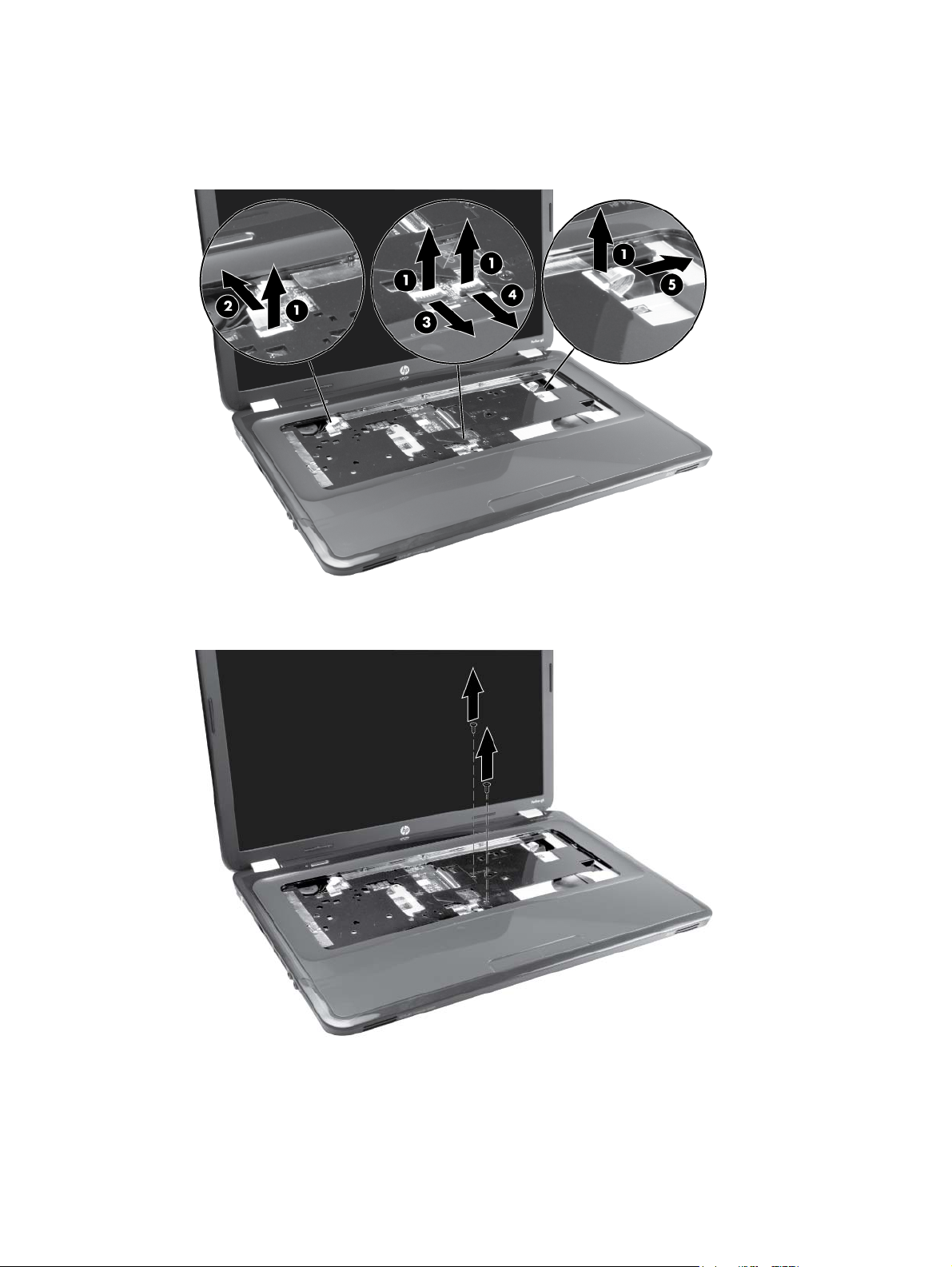
2. Release the three ZIF connectors (1) to which the ZIF cables are attached. Then disconnect the
power button cable (2), the TouchPad cable (3), the TouchPad button cable (4), and USB board
cable (5) from the system board.
3. Remove the two Phillips 5.0×2.5 screws that secure the top cover to the computer.
4. Turn the computer upside down, with the front toward you.
Component replacement procedures
61
Page 70
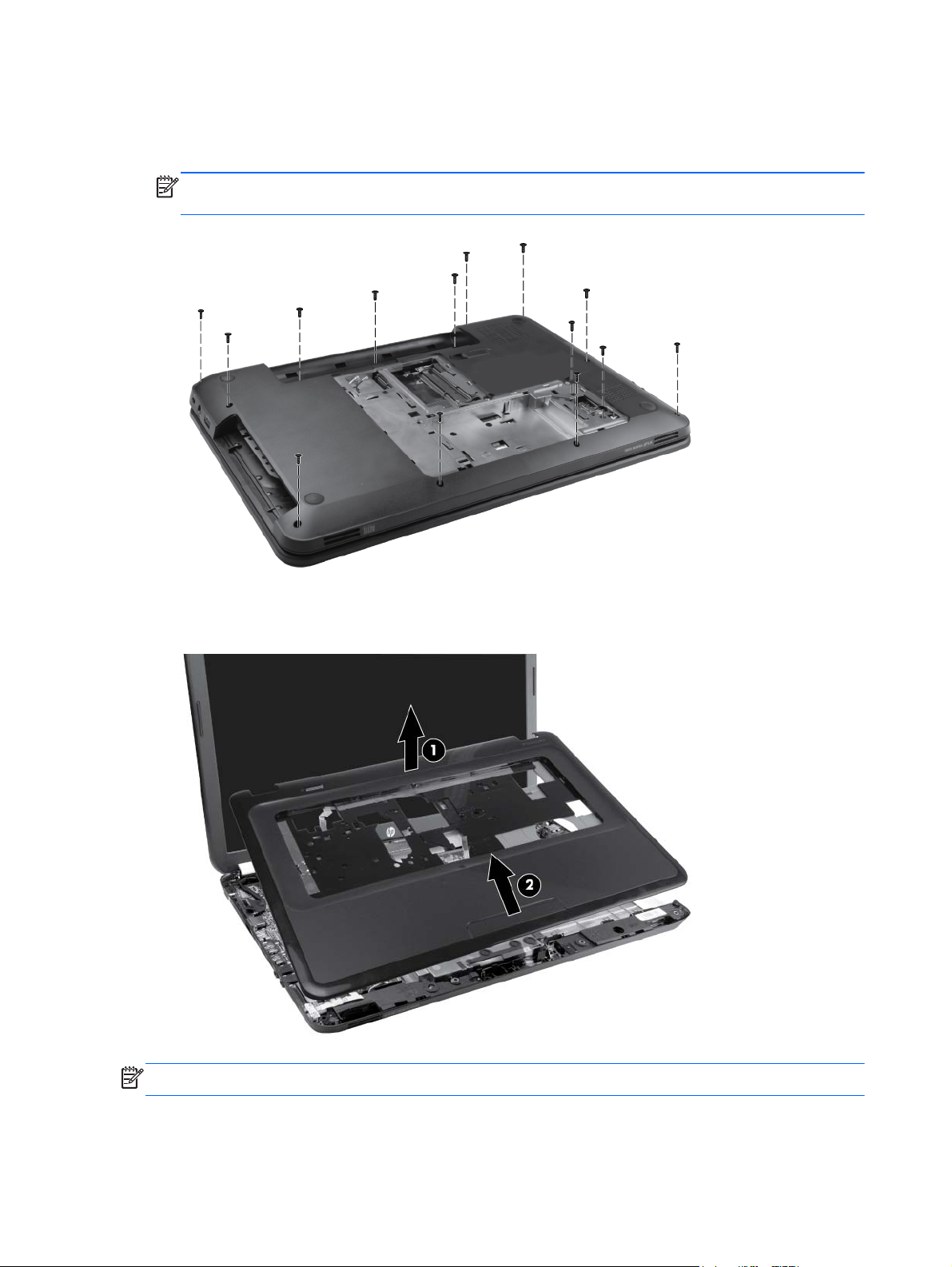
5. Remove the three Phillips 5.0×2.5 screws in the battery bay, the two Phillips 5.0×2.5 screws near
the hard drive connector, and the nine Phillips 6.0×2.5 screws along the edges of the base
enclosure.
NOTE: The four screws along the front edge also serve to secure the speakers inside the base
enclosure.
6. Lift the rear edge of the top cover (1) until the top cover disengages from the base enclosure.
Remove the top cover (2).
NOTE: The TouchPad is glued to the top cover and is included with the top cover spare part.
Reverse this procedure to install the top cover.
62 Chapter 4 Removal and replacement procedures
Page 71
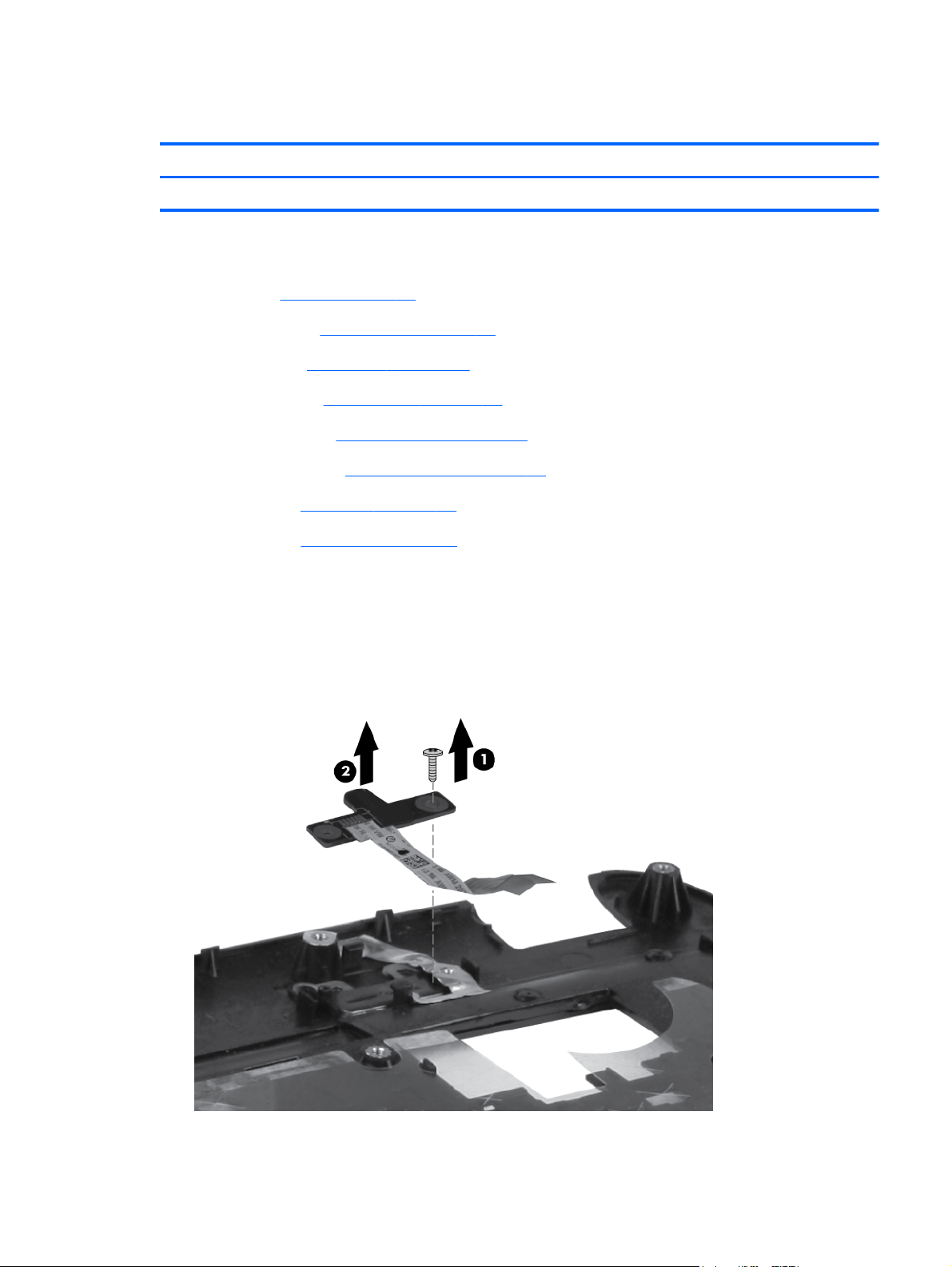
Power button board
Description Spare part number
Power button board (includes cable) 641144-001
Before removing the power button board, remove the following components:
1. Battery (see
2. Service door (see
3. Hard drive (see
4. Optical drive (see
5. WLAN module (see
6. Memory module (see
7. Keyboard (see
8. Top cover (see
Battery on page 48)
Service door on page 49)
Hard drive on page 50)
Optical drive on page 52)
WLAN module on page 54).
Memory module on page 56)
Keyboard on page 57)
Top cover on page 60)
Remove the power button board:
1. Position the top cover upside down, with the rear edge toward you.
2. Remove the Phillips 3.0×2.0 screw (1) that secures the power button board to the top cover.
3. Lift up and remove the power button board (2).
Component replacement procedures
63
Page 72

Reverse this procedure to install the power button board.
64 Chapter 4 Removal and replacement procedures
Page 73

TouchPad button board
Description Spare part number
TouchPad button board (includes bracket and cable) 641143-001
Before removing the TouchPad button board, remove the following components:
1. Battery (see
2. Service door (see
3. Hard drive (see
4. Optical drive (see
5. Keyboard (see
6. Top cover (see
Battery on page 48)
Service door on page 49)
Hard drive on page 50)
Optical drive on page 52)
Keyboard on page 57)
Top cover on page 60)
Remove the TouchPad button board:
1. Position the top cover upside down, with the front toward you.
2. Release the ZIF connector (1), and then disconnect the TouchPad LED ZIF cable (2) from the
TouchPad button.board.
3. Remove the Phillips 2.0×3.0 screw (3) that secures the TouchPad bracket to the top cover.
4. Lift up and remove the TouchPad button board bracket (4). The TouchPad button is fused onto the
TouchPad button board bracket.
Component replacement procedures
65
Page 74

Reverse the above procedure to reassemble and install the TouchPad button board.
66 Chapter 4 Removal and replacement procedures
Page 75

TouchPad LED board
NOTE: The security cable lock is included with the base enclosure, spare part number 637187-001.
TouchPad LED board 647622-001
Before removing the TouchPad LED board, remove the following components:
1. Battery (see
2. Service door (see
3. Hard drive (see
4. Optical drive (see
5. Keyboard (see
6. Top cover (see
Remove the TouchPad LED board:
1. Position the computer right-side up.
2. Release the ZIF connector (1), and disconnect the LED ZIF cable (2) from the system board.
3. Remove the LED board (3).
Battery on page 48)
Service door on page 49)
Hard drive on page 50)
Optical drive on page 52)
Keyboard on page 57)
Top cover on page 60)
Reverse this procedure to install the TouchPad LED board.
Component replacement procedures
67
Page 76

Speaker assembly
Description Spare part number
Speaker assembly (includes cable) 641396-001
Before removing the speaker assembly, remove the following components:
1. Battery (see
2. Service door (see
3. Hard drive (see
4. Optical drive (see
5. Keyboard (see
6. TouchPad top cover (see
7. TouchPad LED board (see
Battery on page 48)
Service door on page 49)
Hard drive on page 50)
Optical drive on page 52)
Keyboard on page 57)
Top cover on page 60)
TouchPad LED board on page 67)
Remove the speaker assembly:
1. Disconnect the speaker cable (1) from the system board.
2. Gently pry back the tabs on the base enclosure (2) to release the speakers, and then lift up to
remove the speakers (3).
Reverse this procedure to install the speaker assembly.
68 Chapter 4 Removal and replacement procedures
Page 77

USB board
Description Spare part number
USB board (includes cable) 641145-001
Before removing the USB board, remove the following components:
1. Battery (see
2. Service door (see
3. Hard drive (see
4. Optical drive (see
5. Keyboard (see
6. Top cover (see
Battery on page 48)
Service door on page 49)
Hard drive on page 50)
Optical drive on page 52)
Keyboard on page 57)
Top cover on page 60)
Remove the USB board:
1. Position the computer right-side up.
2. Release the clips (1) that secure the USB board to the base enclosure.
3. Lift the USB board (2) straight up and remove it from the computer.
Reverse this procedure to install the USB board.
Component replacement procedures
69
Page 78

Power connector
Description Spare part number
Power connector 641137-001
Before removing the power connector cable, remove the following components:
1. Battery (see
2. Service door (see
3. Hard drive (see
4. Optical drive (see
5. Keyboard (see
6. Top cover (see
Battery on page 48)
Service door on page 49)
Hard drive on page 50)
Optical drive on page 52)
Keyboard on page 57)
Top cover on page 60)
Remove the power connector:
1. Position the computer right-side up.
2. Disconnect the power connector cable (1) from the system board.
3. Lift the power connector (2) away from the clips built into the base enclosure.
Reverse this procedure to install the power connector.
70 Chapter 4 Removal and replacement procedures
Page 79

Display assembly
Description Spare part number
39.6-cm (15.6-in) High Definition (HD), light-emitting diode (LED) BrightView display assembly:
For use in Charcoal Grey computer models 645523-001
●
For use in Ocean Drive computer models 636378-001
●
For use in Sonoma Red computer models 645521-001
●
For use in Luminous Rose computer models 645522-001
●
For use in Pewter computer models 645524-001
●
For use in Pacific Blue computer models 645525-001
●
For use in Pearl Pink computer models 645526-001
●
For use in Sweet Purple computer models 645527-001
●
For use in Butter Gold computer models 645528-001
●
Before removing the display assembly, remove the following components:
1. Battery (see
2. Service door (see
3. Optical drive (see
4. WLAN module (see
5. Keyboard (see
6. Top cover (see
7. USB board (see
8. Power connector (see
Battery on page 48)
Service door on page 49)
Optical drive on page 52)
WLAN module on page 54)
Keyboard on page 57)
Top cover on page 60)
USB board on page 69)
Power connector on page 70)
Remove the display assembly:
1. Position the computer display-side up, with the front toward you.
2. Open the display as far as possible.
3. Disconnect the display panel cable (1) from the system board.
4. Pull the antenna cables through the opening in the base enclosure (2), and then disengage the
cables from the clip in the routing channel leading to the display hinge.
CAUTION: Support the display assembly when removing the display screws in the following
steps. Failure to support the display assembly can result in damage to the assembly and other
components.
5. Remove the two Phillips 6.0×2.5 screws (3) that secure the display assembly to the computer.
Component replacement procedures
71
Page 80
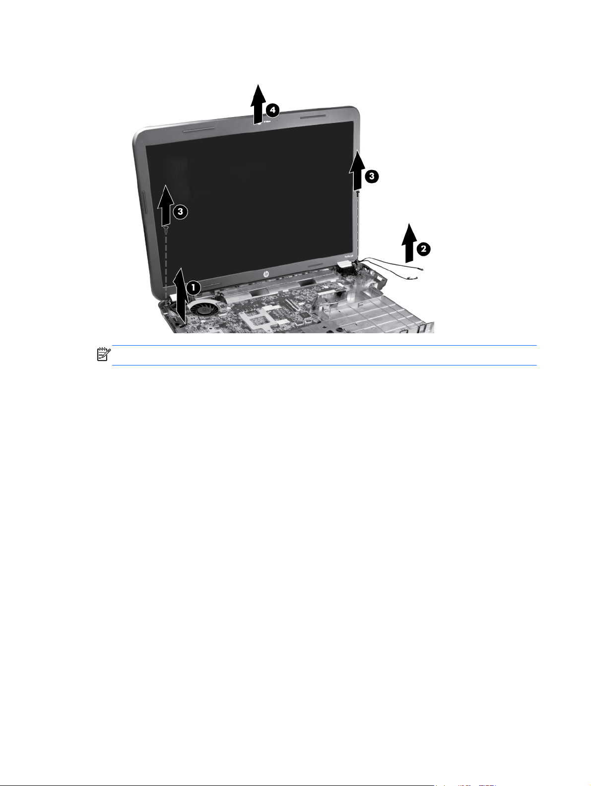
6. Lift the display panel (4) straight up to remove it.
NOTE: The security bracket is part of the right hinge.
Reverse this procedure to install the display assembly.
72 Chapter 4 Removal and replacement procedures
Page 81
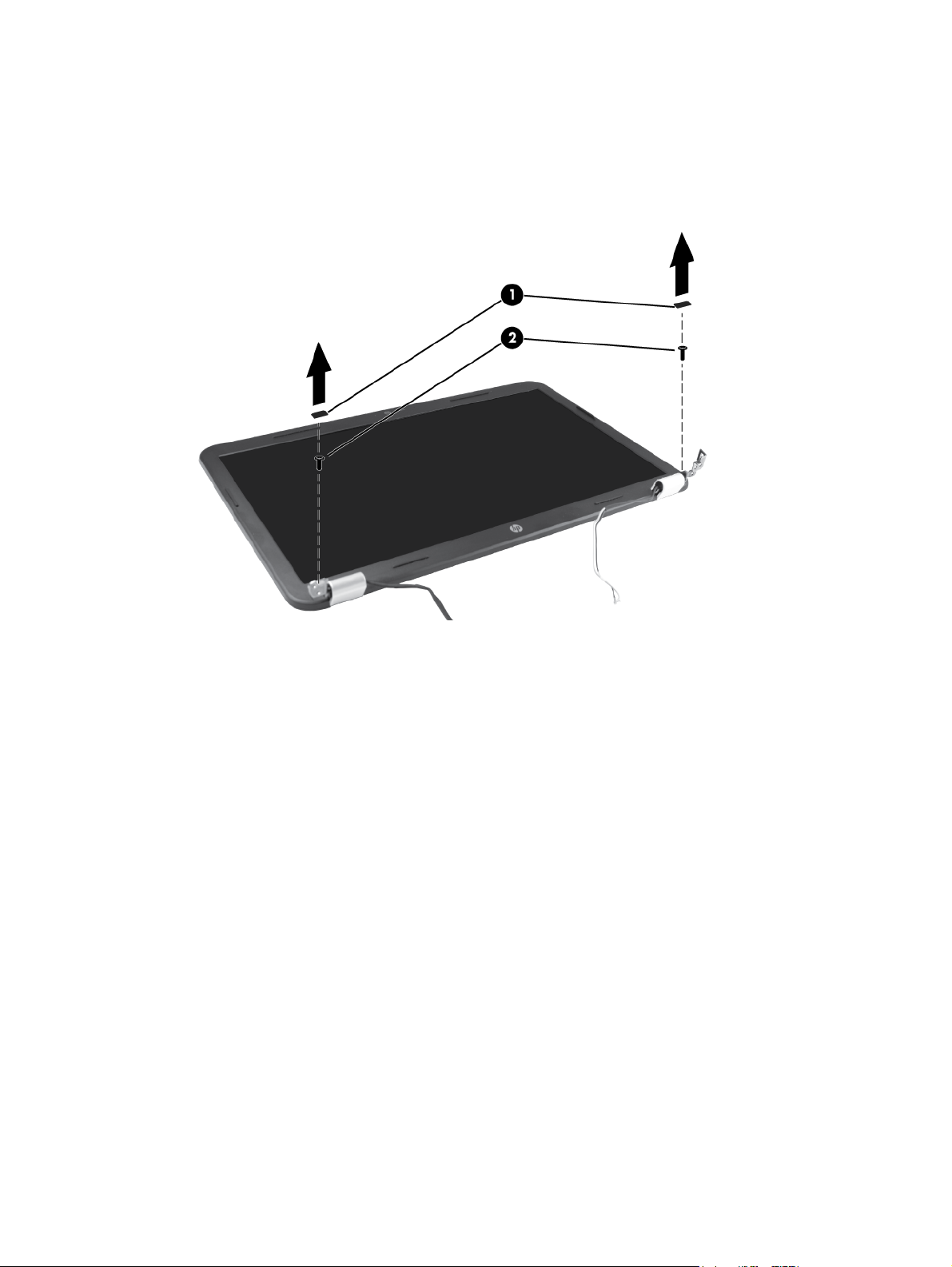
7. To replace any of the display assembly internal components, remove the following screw covers
and screws:
(1) Two screw covers on the display bezel bottom edge
(2) Two Phillips 5.0×2.5 screws
8. Flex the inside edge of the left side (1), the top and bottom sides (2), and the right side (3) of the
display bezel until the bezel disengages from the display back cover.
Component replacement procedures
73
Page 82
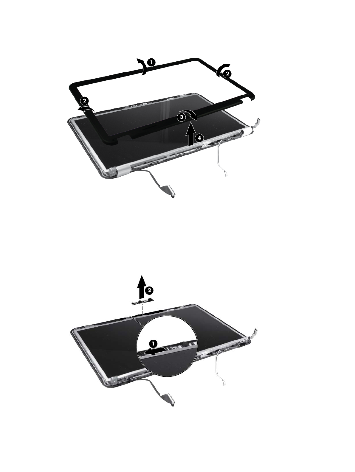
9. Remove the display bezel (4).
Reverse this procedure to install the display bezel.
10. To replace the webcam module, lift the webcam module as far from the display enclosure as the
webcam module cable allows.
11. Disconnect the webcam module cable (1) from the webcam module, and then remove the
webcam module (2). The webcam module is available using spare part number 637197-001.
Reverse this procedure to install the webcam module.
74 Chapter 4 Removal and replacement procedures
Page 83
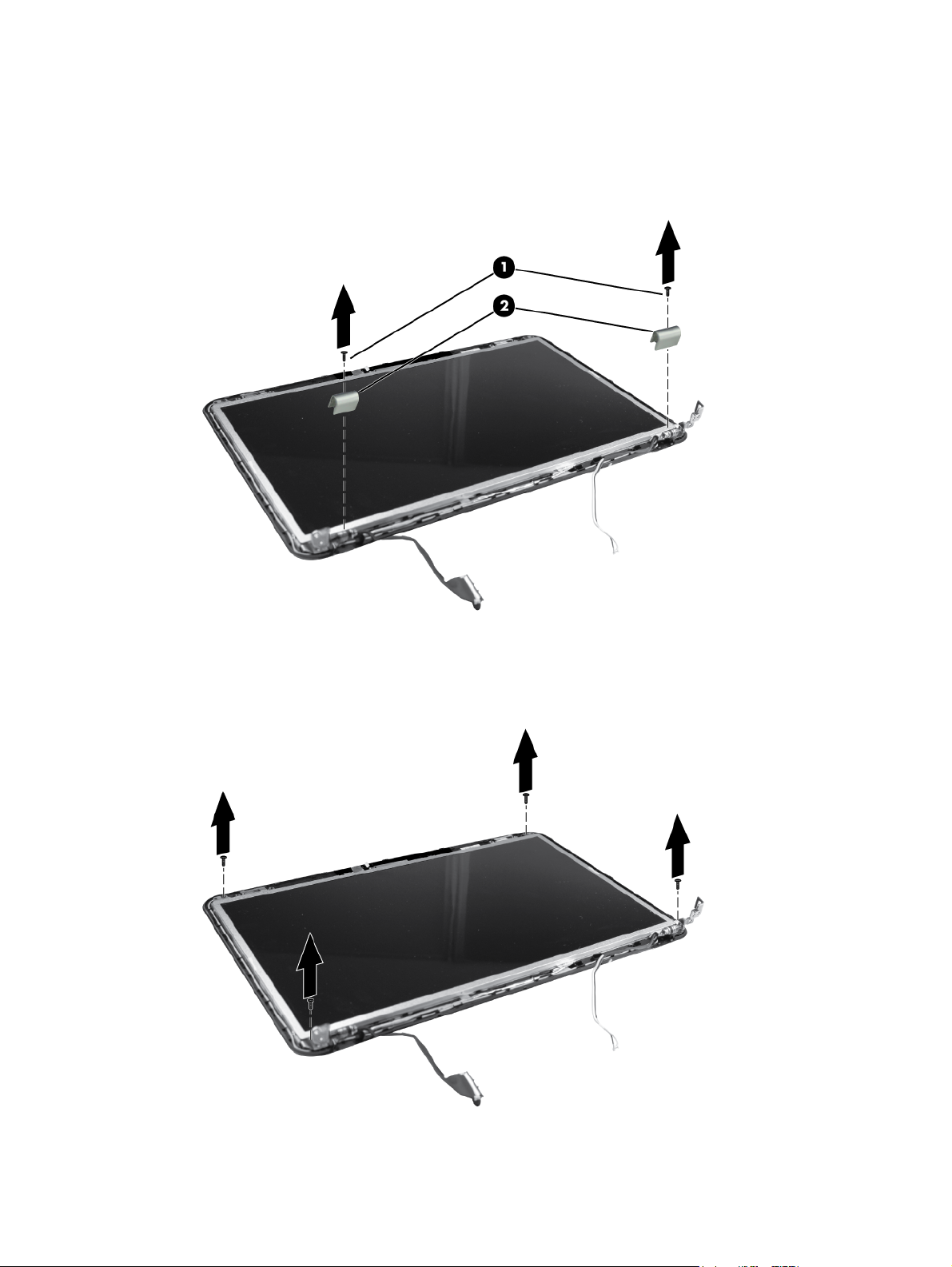
12. To replace the display hinge covers, remove the two Phillips 3.0×2.5 screws (1) that secure the
covers to the display enclosure.
13. Remove the display hinge covers (2). The display hinge covers are available using spare part
number 641142-001.
Reverse this procedure to install the display hinge covers.
14. To replace the display panel, remove four Phillips 4.0×2.5 screws that secure the display panel to
the display enclosure.
Component replacement procedures
75
Page 84
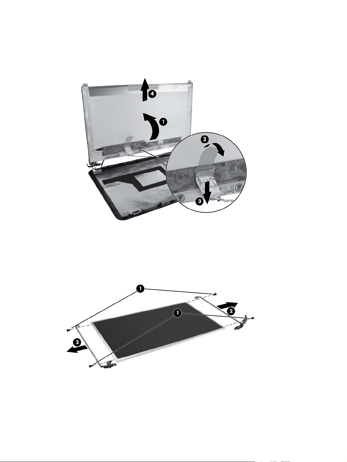
15. Tilt the display (1) up, release the tape (2) holding the display cable to the display panel, and
then disconnect the cable (3).
16. Remove the display panel (4) from the display enclosure. The display panel is available using
spare part number 647623-001 .
Reverse this procedure to install the display panel.
17. To replace the display panel brackets, remove the two Phillips 3.0×2.0 screws (1) that secure
each bracket to the display panel.
18. Remove the display brackets (2) from the display panel. The display brackets are available using
spare part number 637191-001.
Reverse this procedure to install the display hinges.
19. To replace the wireless transceivers, lift up on the silver transceivers (1), and then release the
adhesive material from the display cover.
76 Chapter 4 Removal and replacement procedures
Page 85
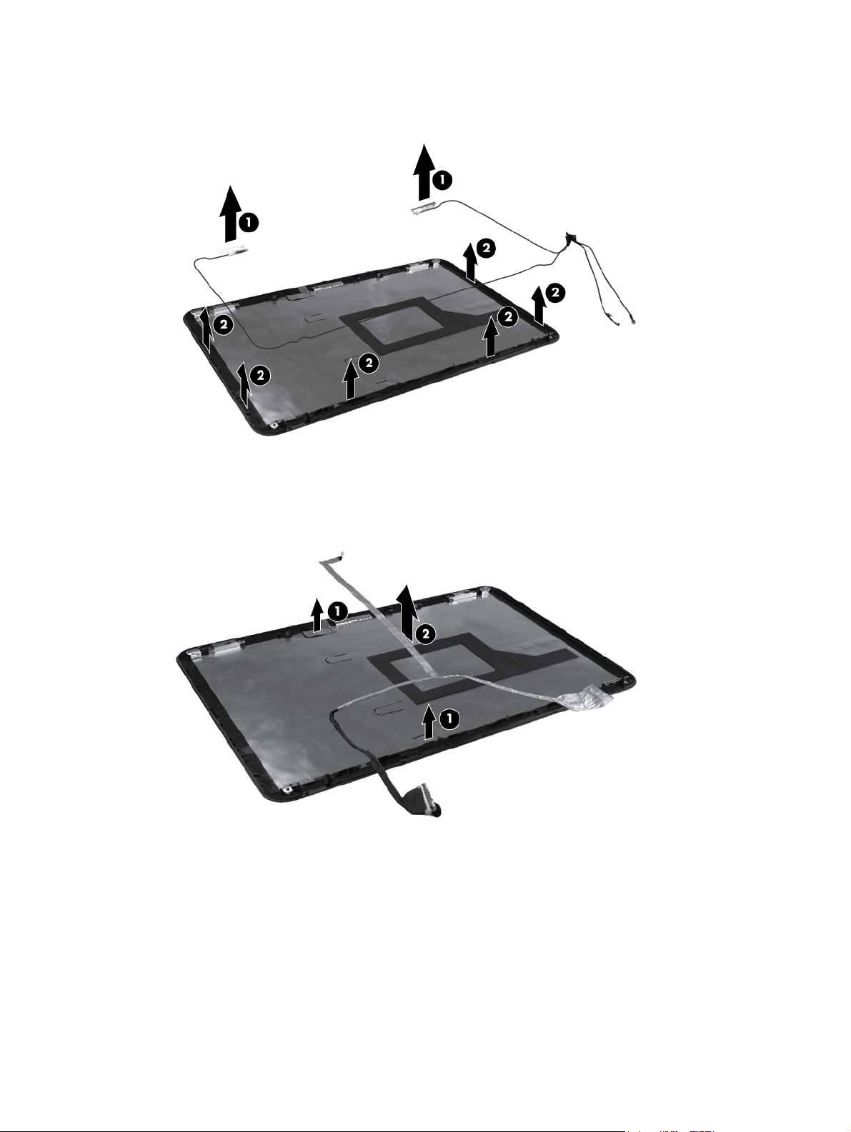
20. Lift up to remove the transceiver cable (2). The wireless antenna transceivers and cable are
available using spare part number 637185-001.
Reverse this procedure to install the display wireless antenna transceivers.
21. To remove the display cable from the display enclosure, lift the adhesive tabs (1) that hold the
display cable to the display enclosure. Gently peel the display cable (2) away from the adhesive
that holds the cable to the display panel.
Reverse this procedure to install the display panel.
Component replacement procedures
77
Page 86

System board
NOTE: The system board spare part kit includes UMA or discrete graphics subsystem memory and
replacement thermal material.
Description Spare part number
For use in Intel HM55 UMA computer models 636370-001
For use in Intel HM65 UMA computer models 636373-001
For use in Intel HM55 6470 discrete, 512 MB, computer models 636371-001
For use in Intel HM55 6470 discrete, 1 GB, computer models 636372-001
For use in Intel HM65 discrete, 512 MB computer models 636374-001
For use in Intel HM65 6470 discrete, 1 GB, computer models 636375-001
For use in AMD UMA computer models 638856-001
For use in AMD 6470 discrete, 512 MB computer models 638854-001
For use in AMD 6470 discrete, 1 GB computer models 638855-001
For use in AMD E-350 UMA computer models 645529-001
For use in AMD 880MD 6470 discrete, 512 MB, BACO computer models 647626-001
For use in AMD 880MD 6470 discrete, 1 GB, BACO computer models 647627-001
For use in AMD A60M UMA computer models 649948-001
For use in AMD A60M HD6470 discrete, 512 MB computer models 649949-001
For use in AMD A60M HD6470 discrete, 1 GB computer models 649950-001
For use in Intel HM65 6470 discrete, 512 MB, BACO, computer models 650198-001
For use in Intel HM65 6470 discrete, 1 GB BACO, computer models 650199-001
Foruse in Intel HM55 i3–370M discrete, 512 MB/1 GB computer models 654117-001
For use in Intel HM55 i3–370M UMA computer models 654118-001
When replacing the system board, be sure that the following components are removed from the
defective system board and installed on the replacement system board:
Memory modules (see
●
WLAN module (see
●
Memory module on page 56)
WLAN module on page 54)
Before removing the system board, remove the following components:
1. Battery (see
Battery on page 48)
2. Service door (see
3. Hard drive (see
Service door on page 49)
Hard drive on page 50)
78 Chapter 4 Removal and replacement procedures
Page 87

4. Optical drive (see Optical drive on page 52)
5. WLAN module (see
6. Memory module (see
7. Keyboard (see
8. Top cover (see
9. USB board (see
10. Display assembly (see
11. Power connector (see
12. TouchPad LED board (see
WLAN module on page 54)
Memory module on page 56)
Keyboard on page 57)
Top cover on page 60)
USB board on page 69)
Display assembly on page 71)
Power connector on page 70)
TouchPad LED board on page 67)
Remove the system board:
1. Disconnect the optical drive connector from the system board (1) .
2. Remove the Phillips 5.0×2.0 screw (2) that secures the system board to the base enclosure.
Component replacement procedures
79
Page 88
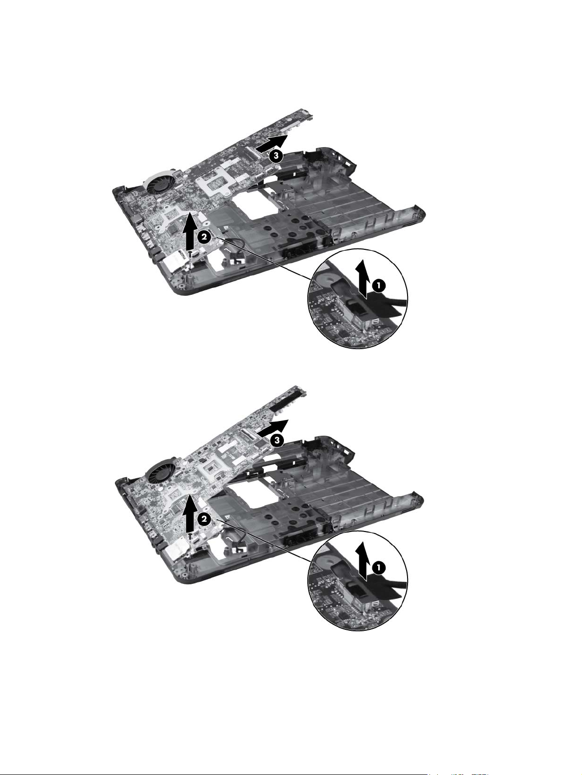
3. Lift the system board (3) from the right edge and pull it away from the base enclosure at an angle.
For AMD computer models, see the following image.
For Intel computer models, see the following image.
80 Chapter 4 Removal and replacement procedures
Page 89

When replacing the system board, be sure that the following components are removed from the
defective system board and installed on the replacement system board:
Heat sink assembly (see
●
Processor (see
●
Processor on page 88)
Heat sink assembly on page 84)
Reverse this procedure to install the system board.
Component replacement procedures
81
Page 90

RTC battery
Description Spare part number
RTC battery (includes mounting adhesive) 637193-001
Before removing the RTC battery, remove the following components:
1. Battery (see
2. Service door (see
3. Hard drive (see
4. Optical drive (see
5. WLAN module (see
6. Memory module (see
7. Keyboard (see
8. Top cover (see
Battery on page 48)
Service door on page 49)
Hard drive on page 50)
Optical drive on page 52)
WLAN module on page 54)
Memory module on page 56)
Keyboard on page 57)
Top cover on page 60)
9. TouchPad LED board (see
10. USB board (see
11. Power connector (see
12. Display assembly (see
13. System board (see
USB board on page 69)
Power connector on page 70)
USB board on page 69)
System board on page 78)
Remove the RTC battery:
TouchPad LED board on page 67)
1. Position the system board face up, with the front toward you.
2. Disconnect the RTC battery connector from the system board (1).
82 Chapter 4 Removal and replacement procedures
Page 91
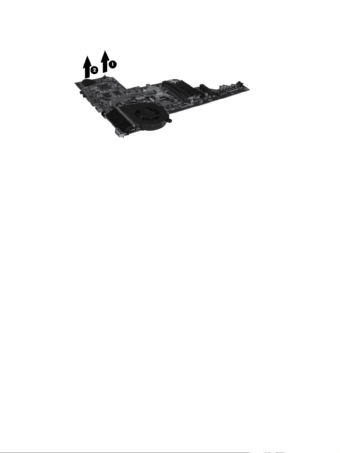
3. Remove the RTC battery (2).
Reverse this procedure to install the RTC battery.
Component replacement procedures
83
Page 92

Heat sink assembly
NOTE: The heat sink assembly includes replacement thermal material. The heat sink fan is available
separately, using spare part number 639460-001.
Description Spare part number
For use in AMD UMA computer models 639463-001
For use in AMD discrete computer models 639462-001
For use in AMD BGA UMA computer models 649952-001
For use in AMD A60M discrete computer models 649953-001
For use in AMD A60M UMA computer models 649954-001
For use in Intel HM55 UMA computer models 637189-001
For use in Intel HM55 discrete computer models 637190-001
For use in Intel HM65 UMA computer models 641140-001
For use in Intel HM65 discrete computer models 641141-001
For use in Intel BGA discrete computer models 654119-001
For use in Intel BGA UMA computer models 654120-001
Before removing the heat sink assembly, remove the following components:
1. Battery (see
2. Service door (see
3. Hard drive (see
4. Optical drive (see
5. WLAN module (see
6. Memory module (see
7. Keyboard (see
8. Top cover (see
9. USB board (see
10. Display assembly (see
11. Power connector (see
12. System board (see
Battery on page 48)
Service door on page 49)
Hard drive on page 50)
Optical drive on page 52)
WLAN module on page 54)
Memory module on page 56)
Keyboard on page 57)
Top cover on page 60)
USB board on page 69)
Display assembly on page 71)
Power connector on page 70)
System board on page 78)
Remove the heat sink assembly (heat sink appearance may vary):
84 Chapter 4 Removal and replacement procedures
Page 93

NOTE: Steps 1 through 5 apply only to computer models equipped with Intel processors.
1. Position the system board right-side up, with the front toward you.
2. Disconnect the fan cable from the system board (1).
3. Follow the sequence embossed on heat sink to loosen the seven Phillips 10.0×2.0 captive screws
(2) that secure the heat sink assembly to the system board.
NOTE: Due to the adhesive quality of the thermal material located between the heat sink
assembly and system board components, it might be necessary to move the heat sink assembly
from side to side to detach the assembly.
4. Remove the heat sink assembly (3) by lifting it straight up.
NOTE: Steps 6 through 10 apply only to computer models equipped with AMD processors.
5. Position the system board right-side up, with the front toward you.
6. Disconnect the fan cable from the system board (1).
7. Remove the three Phillips 3.0×2.0 screws (2) that secure the heat sink assembly to the system
board.
NOTE: Due to the adhesive quality of the thermal material located between the heat sink
assembly and system board components, it might be necessary to move the heat sink assembly
from side to side to detach the assembly.
8. Follow the sequence embossed on the heat sink to loosen the three Phillips 10.0×2.0 captive
screws (3) that secure the heat sink assembly to the system board.
Component replacement procedures
85
Page 94

9. Remove the heat sink assembly (4) by lifting straight up.
Each time the heat sink assembly is removed, the thermal material must be thoroughly cleaned from the
system board at locations (1) and (2), from the heat sink assembly at locations (4) and (5), and from
the processor (3). Thermal pads and thermal paste must be installed on all surfaces before the heat sink
assembly is reinstalled.
NOTE: Thermal pads and thermal paste are included with all heat sink assembly, system board, and
processor spare part kits.
The following illustration shows the locations for thermal material on systems with Intel processors.
Each time the heat sink assembly is removed, the thermal material must be thoroughly cleaned from the
system board at locations (1), (2), and (3), from the heat sink assembly at locations (5), (6), and (7),
and from the processor (4). Thermal pads and thermal paste must be installed on all surfaces before
the heat sink assembly is reinstalled.
86 Chapter 4 Removal and replacement procedures
Page 95

The following illustration shows the locations for thermal material on systems with AMD processors.
After applying fresh thermal paste to the components, reverse the above procedure to install the heat
sink assembly.
Component replacement procedures
87
Page 96

Processor
NOTE: All processor spare part kits include thermal material.
Description Spare part number
Intel Core i7-2620M processor (2.7 GHz, SC turbo up to 3.40 GHz, 4 MB L3 cache), Dual 35 W 631252-001
Intel Core i5-2540M processor (2.6 GHz, SC turbo up to 3.3 GHz, 3 MB L3 cache), Dual 35 W 631255-001
Intel Core i5-2520M processor (2.5 GHz, SC turbo up to 3.2 GHz, 3 MB L3 cache), Dual 35 W 631253-001
Intel Core i5-2430M processor (2.4 GHz, SC turbo up to 3.0 GHz, 3 MB L3 cache), Dual 35 W 653341-001
Intel Core i5-2410M processor (2.3 GHz, SC turbo up to 2.9 GHz, 3 MB L3 cache), Dual 35 W 638039-001
Intel Core i3-2350M processor ( 2.3 GHz, 3 MB L3 cache) Dual 35 W 653340-001
Intel Core i3-2330M processor ( 2.2 GHz, 3 MB L3 cache) Dual 35 W 653339-001
Intel Core i3-2310M processor (2.1 GHz, 3 MB L3 cache) Dual 35 W 638037-001
Intel Core i5-480M processor (2.66 GHz, SC turbo up to 2.93 GHz, 3 MB L3 cache), Dual 35 W 634693-001
Intel Core i3-390M processor (2.66 GHz, 3 MB L3 cache), Dual 35 W 634692-001
Intel Core i3-380M processor (2.53 GHz, 3 MB L3 cache), Dual 35 W 625823-001
Intel Pentium B960 processor (2.2 GHz, 2 MB L3 cache) Dual 35 W 664662-001
Intel Pentium B950 processor ( 2.1 GHz, 2 MB L3 cache) Dual 35 W 653338-001
Intel Pentium P6300 processor (2.26 GHz, 3 MB L3 cache), Dual 35 W 635500-001
Intel Pentium P6200 processor (2.13 GHz, 3 MB L3 cache), Dual 35 W 625831-001
AMD A Series APU A8-3500M (2.4 GHz/1.5 GHz, 4 MB L2 cache), Quad 35 W 653350-001
AMD A Series APU A6-3400M (2.3 GHz/1.4 GHz, 4 MB L2 cache), Quad 35 W 653349-001
AMD A Series APU A4-3300M (2.5 GHz/1.9G Hz, 2 MB L2 cache), Dual 35 W 653348-001
AMD A Series APU E2-3000M (2.4 GHz/1.8 GHz, 1 MB L2 cache), Dual 35 W 653351-001
AMD Phenom II N970 processor (2.2 GHz, 2 MB L2 cache, 1333 MHz, 3.6 GT/s), Quad 35 W 635496-001
AMD Phenom II P960 processor (1.8 GHz, 2 MB L2 cache, 1066 MHz, 3.6 GT/s), Quad 25 W 634689-001
AMD Phenom II N870 processor (2.3 GHz, 1.5 MB L2 cache, 1333 MHz, 3.6 GT/s), Triple 35 W 635495-001
AMD Phenom II P860 processor (2.0 GHz, 1.5 MB L2 cache, 1066 MHz, 3.6 GT/s), Triple 25 W 634688-001
AMD Phenom II N850 processor (2.2 GHz, 1.5 MB L2 cache, 1333 MHz, 3.6 GT/s), Triple 35 W 616345-001
AMD Phenom II N660 processor (3.0 GHz, 2 MB L2 cache, 1333 MHz, 3.6 GT/s), Dual 35 W 635494-001
AMD Phenom II P650 processor (2.6 GHz, 2 MB L2 cache, 1066 MHz, 3.6 GT/s), Dual 25 W 634687-001
Turion II P560 processor (2.5 GHz, 2 MB L2 cache, 1066 MHz, 3.6 GT/s), Dual 25 W 634691-001
Athlon II P360 processor (2.3 GHz, 1 MB L2 cache, 1066 MHz, 3.6 GT/s), Dual 25 W 636635-001
Athlon II P340 processor (2.2 GHz, 1 MB L2 cache, 1066 MHz, 3.2 GT/s), Dual 25 W 616343-001
88 Chapter 4 Removal and replacement procedures
Page 97

Description Spare part number
V160 processor (2.4 GHz, 512 KB L2 cache, 1066 MHz, 3.2 GT/s), SC 25 W 636634-001
V140 processor (2.3 GHz, 512 KB L2 cache, 1066 MHz, 3.2 GT/s), SC 25 W 616333-001
Before removing the processor, remove the following components:
1. Battery (see
2. Service door (see
3. Hard drive (see
4. Optical drive (see
5. WLAN module (see
6. Memory module (see
7. Keyboard (see
8. Top cover (see
9. USB board (see
Battery on page 48)
Service door on page 49)
Hard drive on page 50)
Optical drive on page 52)
WLAN module on page 54)
Memory module on page 56)
Keyboard on page 57)
Top cover on page 60)
USB board on page 69)
10. Display assembly (see
11. Power connector (see
12. System board (see
Power connector on page 70)
System board on page 78)
13. Heat sink assembly (see
Remove the processor:
Display assembly on page 71)
Heat sink assembly on page 84)
1. Turn the processor locking screw (1) one half-turn counterclockwise until you hear a click.
Component replacement procedures
89
Page 98
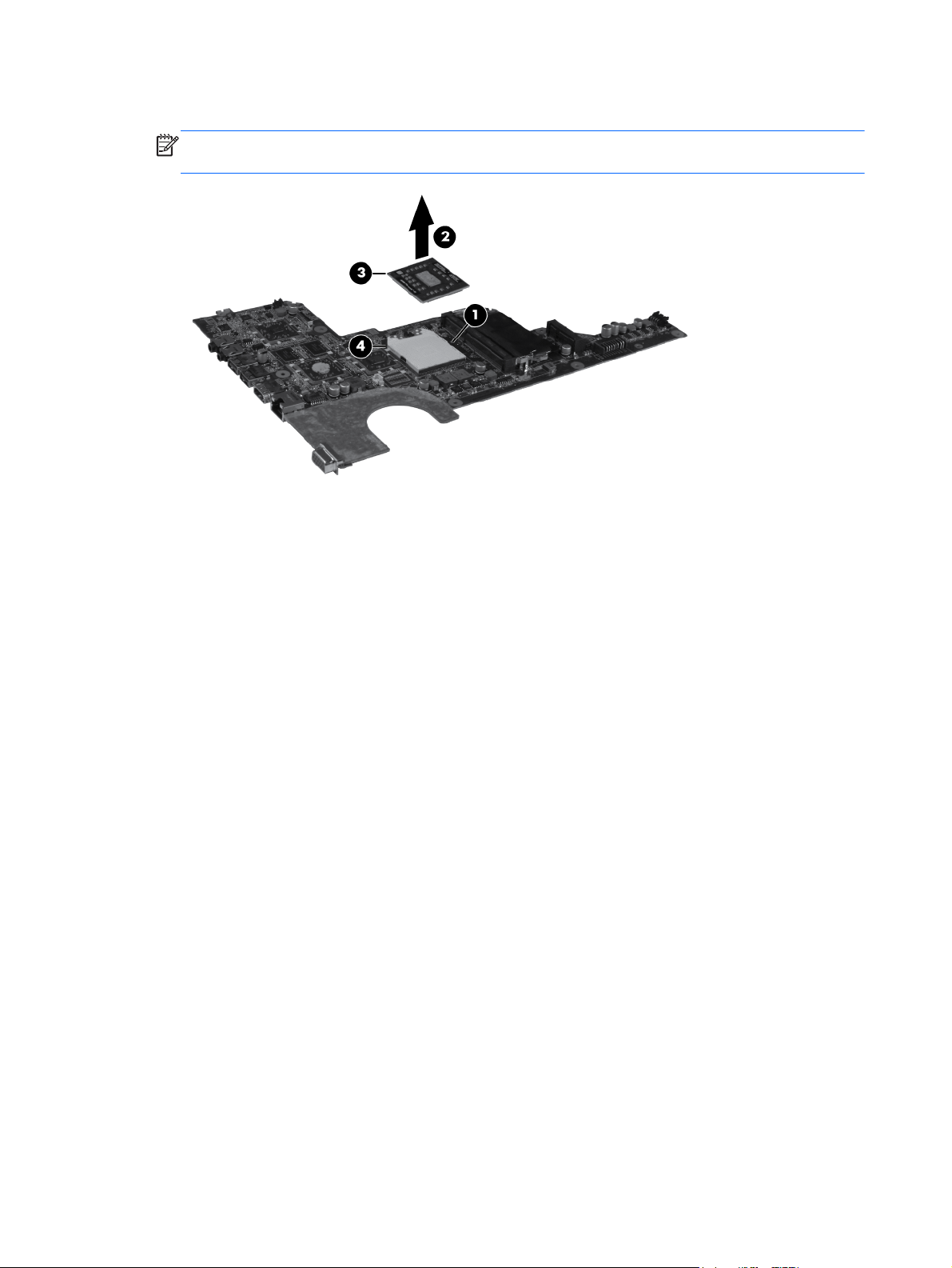
2. Lift the processor (2) straight up and remove it.
NOTE: The gold triangle (3) on the processor must be aligned with the triangle icon (4)
embossed on the processor socket when you install the processor.
Reverse this procedure to install the processor.
90 Chapter 4 Removal and replacement procedures
Page 99

5 Specifications
Computer specifications
Dimensions
Depth 24.5 cm (9.6 in)
Width 37.4 cm (14.7 in)
Height (front to rear) 3.1 to 3.6 cm (1.2 to 1.4 in)
Weight (lowest weight configuration) < 2.5 kg (5.5 lbs)
Input power
Operating voltage 18.5 V dc @ 3.5 A - 65W
Operating current 3.5 A
Temperature
Operating 5°C to 35°C (41°F to 95°F)
Nonoperating -20°C to 60°C (-4°F to 140°F)
Relative humidity
Operating 10% to 90%
Nonoperating 5% to 95%
Maximum altitude (unpressurized)
Operating -15 m to 3,048 m (-50 ft to 10,000 ft)
Nonoperating -15 m to 12,192 m (-50 ft to 40,000 ft)
NOTE: Applicable product safety standards specify thermal limits for plastic surfaces. The computer operates well within this
range of temperatures.
Computer specifications
91
Page 100

39.6-cm (15.6-in) display specifications
Dimensions
Height 21.0 cm (8.27 in)
Width 35.9 cm (14.1 in)
Diagonal 39.6 cm (15.6)
Number of colors Up to 16.8 million
Contrast ratio 300:1 (typical)
Brightness 200 cd/m² (typical)
Pixel resolution
Pitch 0.259 × 0.259 mm
Format 1280 × 800; HD: 1366 × 768
Configuration RGB vertical stripe
Backlight LED
Character display 80 × 25
Total power consumption 4.0 W
Viewing angle ±40° horizontal, +120/-40° vertical (typical)
92 Chapter 5 Specifications
 Loading...