

Page 1

HP Pavilion dv7 Entertainment PC
Maintenance and Service Guide
Page 2

© Copyright 2010 Hewlett-Packard
Development Company, L.P.
Bluetooth is a trademark owned by its
proprietor and used by HewlettPackard Company under license. Intel and
Core are trademarks of Intel Corporation in
the U.S. and other countries. Microsoft,
Windows, and Windows Vista are
U.S. registered trademarks of
Microsoft Corporation. SD Logo is a
trademark of its proprietor.
The information contained herein is subject
to change without notice. The only
warranties for HP products and services are
set forth in the express warranty statements
accompanying such products and services.
Nothing herein should be construed as
constituting an additional warranty. HP shall
not be liable for technical or editorial errors
or omissions contained herein.
First Edition: April 2010
Document Part Number: 597856-001
Page 3

Safety warning notice
WARNING! To reduce the possibility of heat-related injuries or of overheating the computer, do not
place the computer directly on your lap or obstruct the computer air vents. Use the computer only on a
hard, flat surface. Do not allow another hard surface, such as an adjoining optional printer, or a soft
surface, such as pillows or rugs or clothing, to block airflow. Also, do not allow the AC adapter to
contact the skin or a soft surface, such as pillows or rugs or clothing, during operation. The computer
and the AC adapter comply with the user-accessible surface temperature limits defined by the
International Standard for Safety of Information Technology Equipment (IEC 60950).
iii
Page 4

iv Safety warning notice
Page 5

Table of contents
1 Product description ........................................................................................................... 1
2 Components ..................................................................................................................... 6
Top components ....................................................................................................................... 6
TouchPad ................................................................................................................. 6
TouchPad buttons ...................................................................................................... 7
Lights ....................................................................................................................... 8
Buttons and Fingerprint Reader (select models only) ....................................................... 9
Keys ...................................................................................................................... 10
Front components ................................................................................................................... 11
Right-side components ............................................................................................................ 12
Left-side components ............................................................................................................... 13
Bottom components ................................................................................................................ 14
Display components ............................................................................................................... 15
Wireless antennas (select models only) ..................................................................................... 16
Additional hardware components ............................................................................................ 17
3 Illustrated parts catalog .................................................................................................. 18
Service tag ............................................................................................................................ 18
Computer major components ................................................................................................... 20
Display assembly components ................................................................................................. 26
Flush glass display assembly spare parts .................................................................... 26
BrightView panel ..................................................................................................... 27
Mass storage devices ............................................................................................................. 29
Miscellaneous parts ................................................................................................................ 30
Sequential part number listing .................................................................................................. 32
4 Removal and replacement procedures ............................................................................ 39
Preliminary replacement requirements ....................................................................................... 39
Tools required ......................................................................................................... 39
Service considerations ............................................................................................. 39
Plastic parts ............................................................................................. 39
Cables and connectors ............................................................................. 40
v
Page 6

Drive handling ......................................................................................... 40
Grounding guidelines .............................................................................................. 41
Electrostatic discharge damage .................................................................. 41
Packaging and transporting guidelines ........................................ 42
Workstation guidelines .............................................................. 42
Equipment guidelines ................................................................. 43
Component replacement procedures ........................................................................................ 44
Service tag ............................................................................................................. 44
Computer feet ......................................................................................................... 45
Battery ................................................................................................................... 46
Primary hard drive cover .......................................................................................... 47
Hard drive ............................................................................................................. 48
Secondary hard drive .............................................................................................. 50
WLAN module ........................................................................................................ 52
RTC battery ............................................................................................................ 55
Memory module ...................................................................................................... 56
Optical drive .......................................................................................................... 57
Keyboard ............................................................................................................... 58
Top cover ............................................................................................................... 61
Power button board ................................................................................................. 65
Display assembly .................................................................................................... 67
System board ......................................................................................................... 77
USB board ............................................................................................................. 79
Bluetooth module .................................................................................................... 80
Speaker assembly ................................................................................................... 82
Optical drive connector ........................................................................................... 83
Subwoofer ............................................................................................................. 84
Power connector cable ............................................................................................ 85
Fan/heat sink assembly ........................................................................................... 87
Processor ............................................................................................................... 91
5 Setup Utility (BIOS) ......................................................................................................... 93
Starting Setup Utility ............................................................................................................... 93
Using Setup Utility .................................................................................................................. 94
Changing the language of Setup Utility ...................................................................... 94
Navigating and selecting in Setup Utility .................................................................... 94
Displaying system information ................................................................................... 94
Restoring default settings in Setup Utility ..................................................................... 95
Exiting Setup Utility ................................................................................................. 96
Setup Utility menus ................................................................................................................. 96
Main menu ............................................................................................................. 96
Security menu ......................................................................................................... 96
System Configuration menu ...................................................................................... 97
vi
Page 7

Diagnostics menu .................................................................................................... 97
6 Specifications ................................................................................................................. 98
Computer specifications .......................................................................................................... 98
17.3-inch, HD+ flush glass AntiGlare display specifications ........................................................ 99
17.3-inch, HD+ BrightView display specifications .................................................................... 100
Hard drive specifications ...................................................................................................... 101
Blu-ray ROM with LightScribe DVD±R/RW SuperMulti DL Drive ................................................. 102
DVD±RW and CD-RW SuperMulti Double-Layer Combo Drive with LightScribe specifications ........ 103
System DMA specifications .................................................................................................... 103
System interrupt specifications UMA ....................................................................................... 105
System interrupt specifications (discrete) .................................................................................. 106
System interrupt specifications (switchable graphics) ................................................................. 107
System I/O address specifications .......................................................................................... 108
System memory map specifications ......................................................................................... 110
7 Backup and recovery .................................................................................................... 111
Creating recovery discs ........................................................................................................ 112
Backing up your information .................................................................................................. 113
Using Windows Backup and Restore ....................................................................... 114
Using system restore points ..................................................................................... 114
When to create restore points .................................................................. 114
Create a system restore point ................................................................... 114
Restore to a previous date and time .......................................................... 115
Performing a recovery .......................................................................................................... 115
Recovering from the recovery discs .......................................................................... 115
Recovering from the dedicated recovery partition (select models only) ......................... 115
8 Connector pin assignments ........................................................................................... 117
Audio-in (microphone) .......................................................................................................... 117
Audio-out (headphone) ......................................................................................................... 117
External monitor ................................................................................................................... 118
HDMI ................................................................................................................................. 119
RJ-45 (network) .................................................................................................................... 120
Universal Serial Bus .............................................................................................................. 120
9 Power cord set requirements ........................................................................................ 121
Requirements for all countries or regions ................................................................................. 121
Requirements for specific countries or regions .......................................................................... 122
10 Recycling .................................................................................................................... 123
Battery ................................................................................................................................ 123
vii
Page 8

Display ............................................................................................................................... 123
Index ............................................................................................................................... 129
viii
Page 9

1 Product description
Category Description
Product Name HP Pavilion dv7 Entertainment PC
Processors Intel® Core™ i7 processors
Intel Core i7-840QM processor with 1.86-GHz, SC turbo up to 3.2-GHz, Quad
45W (select models only)
Intel Core i7-820QM processor with 1.73-GHz, SC turbo up to 3.06-GHz, Quad
45W (select models only)
Intel Core i7-740QM processor with 1.73-GHz, SC turbo up to 2.93-GHz, Quad
45W (select models only)
Intel Core i7-720QM processor with 1.6-GHz, SC turbo up to 2.8-GHz, Dual 45W
(select models only)
Intel Core i5 processors
Intel Core i5-540M processor with 2.53-GHz, SC turbo up to 3.06-GHz, Dual 35W
Intel Core i5-520M processor with 2.4-GHz, SC turbo up to 2.93-GHz, Dual 35W
Intel Core i5-450M processor with 2.4-GHz, SC turbo, Dual 35W
Intel Core i5-430M processor with 2.26-GHz, SC turbo up to 2.53-GHz, Dual 35W
Intel Core i3 processors
Intel Core i3-370M processor with 2.4-GHz, Dual 35W
Intel Core i3-350M processor with 2.26-GHz, Dual 35W
Intel Pentium® processors
Intel Pentium P6000 processor with 1.86GHz, 1066MHz/3MB L3
Chipset Intel HM55 Express
Graphics Intel HD Graphics
Switchable discrete graphics memory (select models only)
●
ATI Mobility Radeon™ HD 5650 with 1024-MB (64-MB x 16 DDR3 x
800MHz x 8 PCs)
●
ATI Mobility Radeon HD 5470 with 512-MB (64-MB × 16 DDR3 x 800MHz ×
4 PCs)
1
Page 10

Category Description
Supports Blu-ray and/or HD-DVD playback with HD Decode, DX11 support and
HDMI Support (select models only)
Panels
●
17.3-in, SVA HD+ (1600 x 900) LED BrightView
●
17.3-in, SVA HD+ (1600 x 900) LED flush glass AntiGlare
●
Flush glass panel cover support
●
Support for lighted logo on top bezel
Memory 2 customer-accessible/upgradeable SODIMM slots
DDR3, 1333-MHz
Supports dual-channel support
Supports up to 8 GB of system RAM in the following configurations
●
8192-MB total system memory (4096-MB × 2, dual-channel)
●
6144-MB total system memory (2048-MB × 1 + 4096-MB × 1)
●
4096-MB total system memory (2048-MB × 2, dual-channel)
●
3072-MB total system memory (2048-MB × 1 + 1024-MB × 1)
●
2048-MB total system memory (1024-MB × 2, dual-channel)
●
2048-MB total system memory (2048-MB × 1)
Hard drives Supports all Serial ATA (SATA) 9.5-mm/12.5-mm, 6.35-cm (2.50-in) hard drives
Supports up to 2 hard drives
Support for solid-state drives (SSD)
Support for HP ProtectSmart Hard Drive Protection
Dual hard drive configurations:
●
2-TB (1-TB, 5200-rpm × 2)
●
1500-GB (750-GB, 5200-rpm × 2)
●
1280-GB (640-GB, 5400-rpm × 2)
●
1000-GB (500-GB, 7200-rpm x 2)
●
640-GB (320-GB, 7200-rpm × 2)
●
500-GB (250-GB, 7200-rpm × 2)
●
160-GB SSD + 500-GB, 7200-rpm
2 Chapter 1 Product description
Page 11

Category Description
Single hard drive configurations:
●
1-TB, 5200-rpm, 12.5 mm
●
750-GB, 5200-rpm, 12.5 mm
●
640-GB, 5400-rpm, 9.5 mm
●
500-GB, 7200-rpm, 9.5 mm
●
320-GB, 7200-rpm, 9.5 mm
●
250-GB, 7200-rpm, 9.5 mm
●
160-GB, SSD
Optical drives 12.7-mm tray load
Serial ATA
Fixed (1 screw for removal)
Support for the following optical drives:
●
DVD±RW and CD-RW SuperMulti Double-Layer Combo Drive with LightScribe
●
Blu-ray ROM with LightScribe DVD±R/RW SuperMulti DL Drive
Webcam Low-light VGA camera
Fixed (no tilt)
Activity LED
640 × 480 by 24 frames per second
Microphone 2 omnidirectional microphones, dual-array with appropriate software (supports
beam forming, echo cancellation, and noise suppression)
Audio HD Audio (IDT)
Dolby advance audio
Beats Audio
Integrated subwoofer (select models only)
Supports Microsoft® Premium Requirements
Pavilion-branded Altec Lansing speakers
Ethernet Integrated 10/100/1000 network interface card (NIC)
Wireless Integrated wireless local area network (WLAN) options by way of
wireless module:
Atheros AR9285 802.11b/g/n WLAN module
Intel 1000 802.11b/g/n WLAN module
Broadcom 4322 802.11a/b/g/n WLAN module
Broadcom BCM94313 802.11b/g/n WLAN module
3
Page 12

Category Description
External media card 5-in-1 Digital Media Reader
Digital Media Slot supports Secure Digital (SD) Memory Card, MultiMediaCard
(MMC), Secure Digital High Capacity (SDHC), Memory Stick (MS), Memory Stick
Pro (MSP), xD Picture Card (XD)
Internal media card One half-size mini-card slot for WLAN
Ports Audio-in (stereo microphone)
Headphone/line out
eSATA (combined with USB)
High-Definition Multimedia Interface (HDMI) v1.3 supporting 1080p and
1920x1080 at 60Hz and 1920x1200 at 60Hz DVI Mode
Hot Plug/Unplug and auto detect for correct output to wide-aspect
RJ-45 (Ethernet, includes link and activity lights)
USB 2.0 (three ports)
VGA (Dsub 15-pin)
●
1600 x 1200 external resolution at 75Hz
●
1920 x 1200 external resolution at 75Hz
AC Smart Pin adapter
Keyboard/pointing devices 17-in full-size keyboard with numeric keypad
Dura-coat, Island style
Mylar clickpad cover
Clickpad
TouchPad supports 2-way scrolling
Multitouch gestures enabled as default
Taps enabled as default
Power requirements 6-cell 2.55-Ah Li-ion battery
6-cell 2.8-Ah Li-ion battery
9-cell 2.8-Ah Li-ion battery
120-W AC adapter (select models only)
90-W AC adapter (discrete models)
65-W AC adapter (select models only)
Security Kensington Security Lock
Fingerprint reader with Digital Persona software support (select models only)
Operating system Preinstalled:
Windows® 7 Professional (32 and 64 bit)
4 Chapter 1 Product description
Page 13

Category Description
Windows 7 Home Premium (32 and 64 bit)
Windows 7 Home Basic (32 and 64 bit)
Serviceability AC adapter
Battery (system)
Hard drives (2)
Memory module
Optical drive
Mini card components
5
Page 14
2 Components
Top components
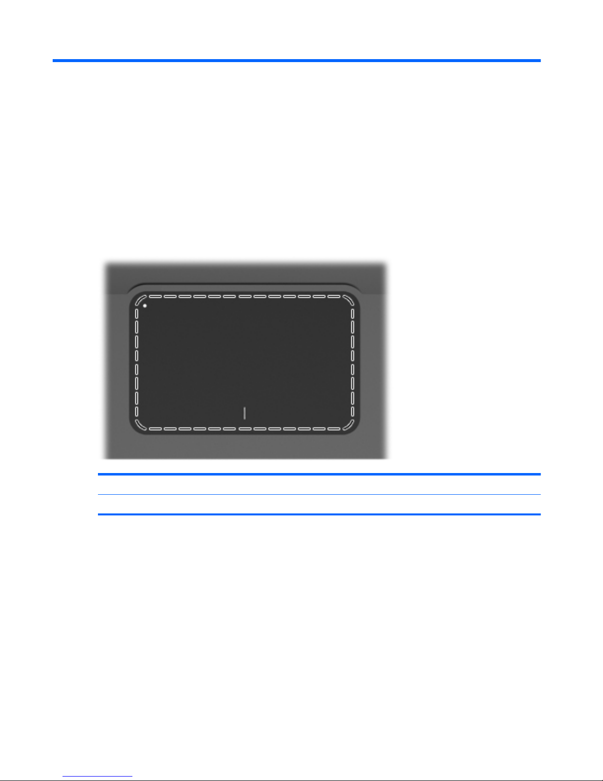
TouchPad
Component Function
TouchPad Moves the pointer and selects or activates items on the screen.
To view or change the pointing device preferences:
1. Select Start > Devices and Printers.
2. Right-click the device representing the computer.
3. Select Mouse settings.
6Chapter 2 Components
Page 15
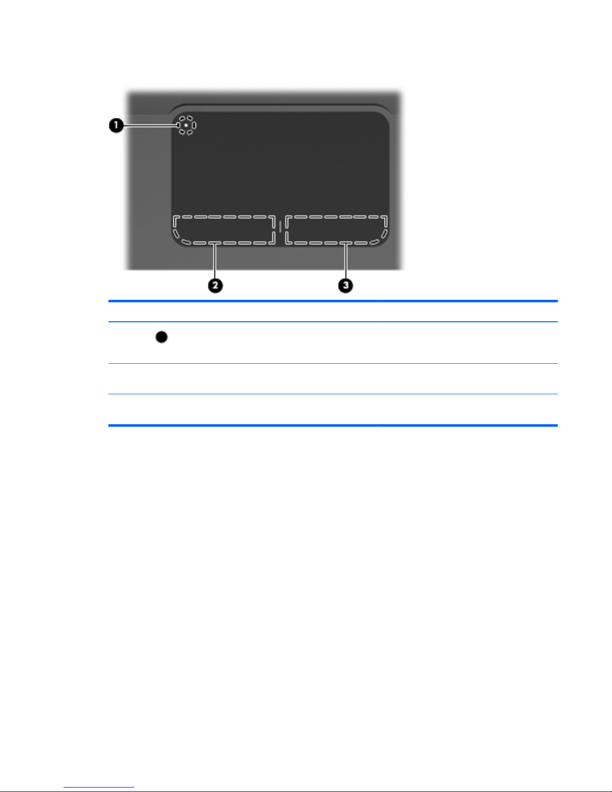
TouchPad buttons
Item Description Function
1
TouchPad On/Off button Turns the TouchPad on and off. Press and hold
the button for two seconds to turn the TouchPad
on and off.
2 Left TouchPad button Functions like the left button on an external
mouse.
3 Right TouchPad button Functions like the right button on an external
mouse.
To view or change pointing device preferences:
1. Select Start > Devices and Printers.
2. Right-click the device representing your computer.
3. Select Mouse settings.
Top components
7
Page 16
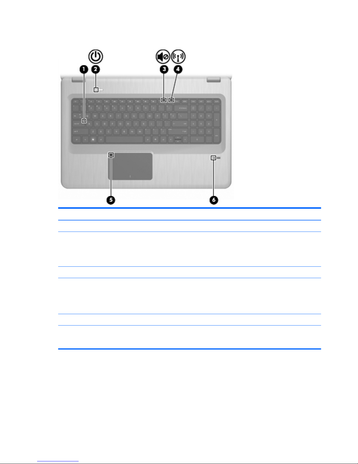
Lights
Item Description Function
1 Caps Lock light On—The Caps Lock is on.
2Power light
●
On—The computer is on.
●
Flashing—The computer is in Sleep.
●
Off—The computer is off or in Hibernation.
3 Volume Mute light Amber—The computer sound is off.
4 Wireless light
●
White—An integrated wireless device, such as a wireless
local area network (WLAN) device and/or a Bluetooth®
device, is detected.
●
Amber—No wireless devices are detected.
5 TouchPad light Amber—The TouchPad is disabled.
6 Fingerprint Reader light
●
White—The fingerprint was read.
●
Amber—The fingerprint was not read.
8Chapter 2 Components
Page 17

Buttons and Fingerprint Reader (select models only)
Item Description Function
1 Power button Press the Power button to:
●
Turn on the computer.
●
Initiate Sleep.
●
Exit Sleep.
●
Exit Hibernation.
If the computer has stopped responding and Windows shutdown
procedures are ineffective, press and hold the Power button for at
least 5 seconds to shut down the computer.
For more information about the power settings, select Start >
Control Panel > System and Security > Power Options.
2 Fingerprint Reader (select models only) Allows a fingerprint logon to Windows, instead of a password
logon.
This table describes the factory settings. For information about changing the factory settings, see Help
and Support.
Top components
9
Page 18
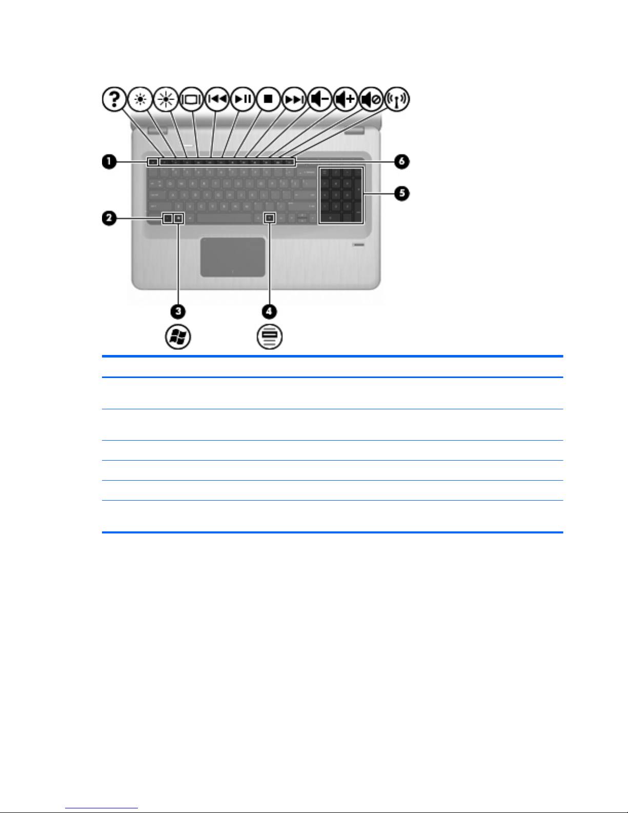
Keys
Item Description Function
1 esc key Press the esc and fn keys at the same time to display system
information.
2 fn key Press the at the same time as a function key or the esc key to
execute frequently used system functions.
3 Windows Logo key Displays the Windows Start menu.
4 Windows Applications key Displays a shortcut menu for items beneath the cursor.
5 Integrated numeric keypad Functions like the keys on an external numeric keypad.
6 Function keys Press a function key and the fn key at the same time to execute
frequently used system functions.
10 Chapter 2 Components
Page 19

Front components
Description Function
Speakers Produce sound.
Front components
11
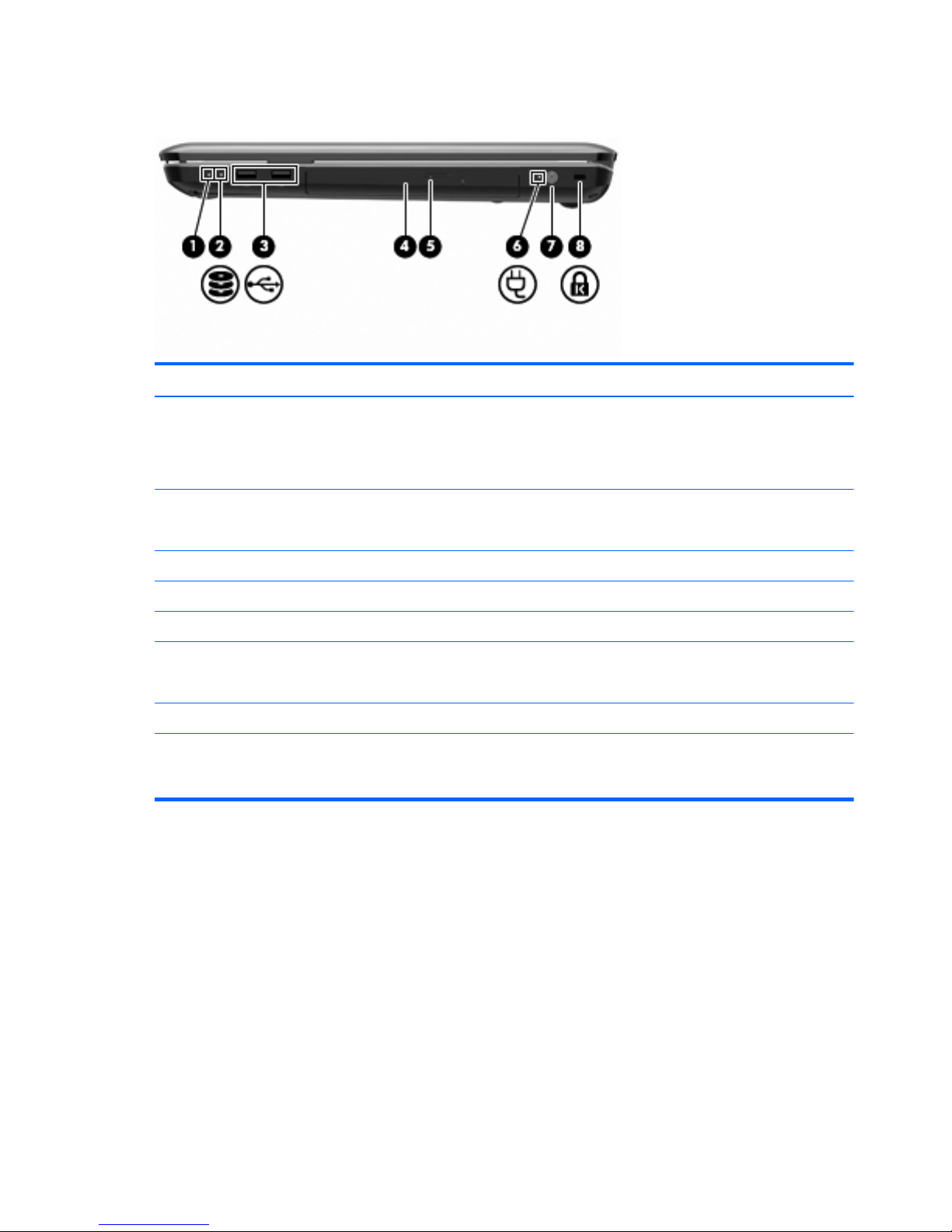
Page 20
Right-side components
Item Description Function
1Power light
●
On—The computer is on.
●
Flashing—The computer is in Sleep.
●
Off—The computer is off or in Hibernation.
2 Hard Disk Drive light
●
White—The hard disk drive is active.
●
Amber—The hard disk drive is parked.
3 USB ports (2) Connect optional USB devices.
4 Optical Drive light Flashing—Accessing the optical drive.
5 Optical drive Reads optical discs and, on select models, writes to optical discs.
6 AC Adapter light
●
On—The computer is connected to external power.
●
Off—The computer is not connected to external power.
7 Power connector Connects an AC adapter.
8 Security Cable slot Connects an optional security cable. The security cable is
designed to act as a deterrent, but might not prevent the computer
from being mishandled or stolen.
12 Chapter 2 Components
Page 21
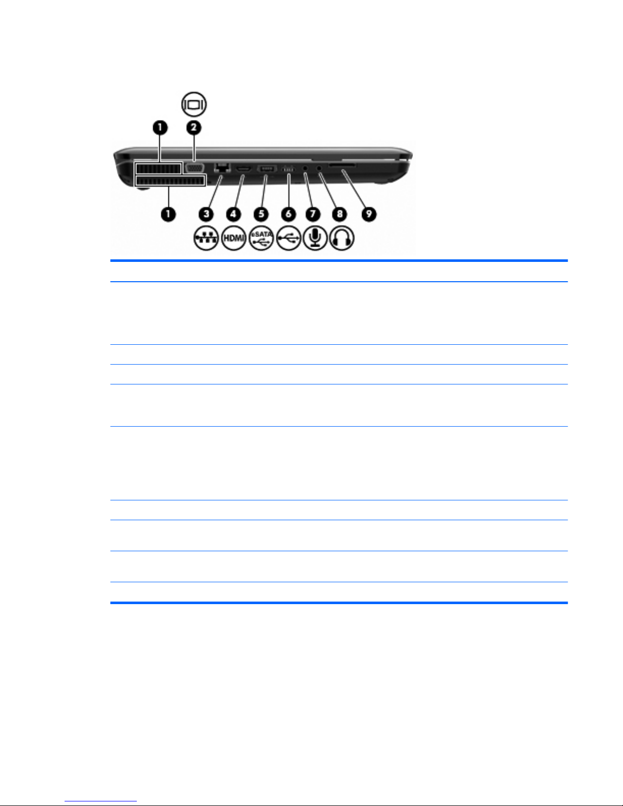
Left-side components
Item Description Function
1 Vents (2) Enable airflow to cool internal components.
NOTE: The computer fan starts up automatically to cool internal
components and prevent overheating. It is normal for the internal
fan to cycle on and off during routine operation.
2 External Monitor port Connects an external VGA monitor or projector.
3 RJ-45 (network) jack Connects a network cable.
4 HDMI port Connects an optional video or audio device, such as a high-
definition television, or any compatible digital or audio
component.
5 eSATA/USB port (select models only) Connects an optional high-performance eSATA component, such
as an eSATA external hard drive, or connects an optional USB
device.
NOTE: Depending on the computer model, the computer might
include only a USB port.
6 USB port Connects an optional USB device.
7 Audio-in (microphone) jack Connects an optional computer headset microphone, stereo array
microphone, monarural microphone.
8 Audio-out (headphone) jack Produces sound when connected to optional powered stereo
speakers, headphones, ear buds, a headset, or television audio.
9 SD card reader Reads SD cards that are inserted into the reader.
Left-side components
13
Page 22
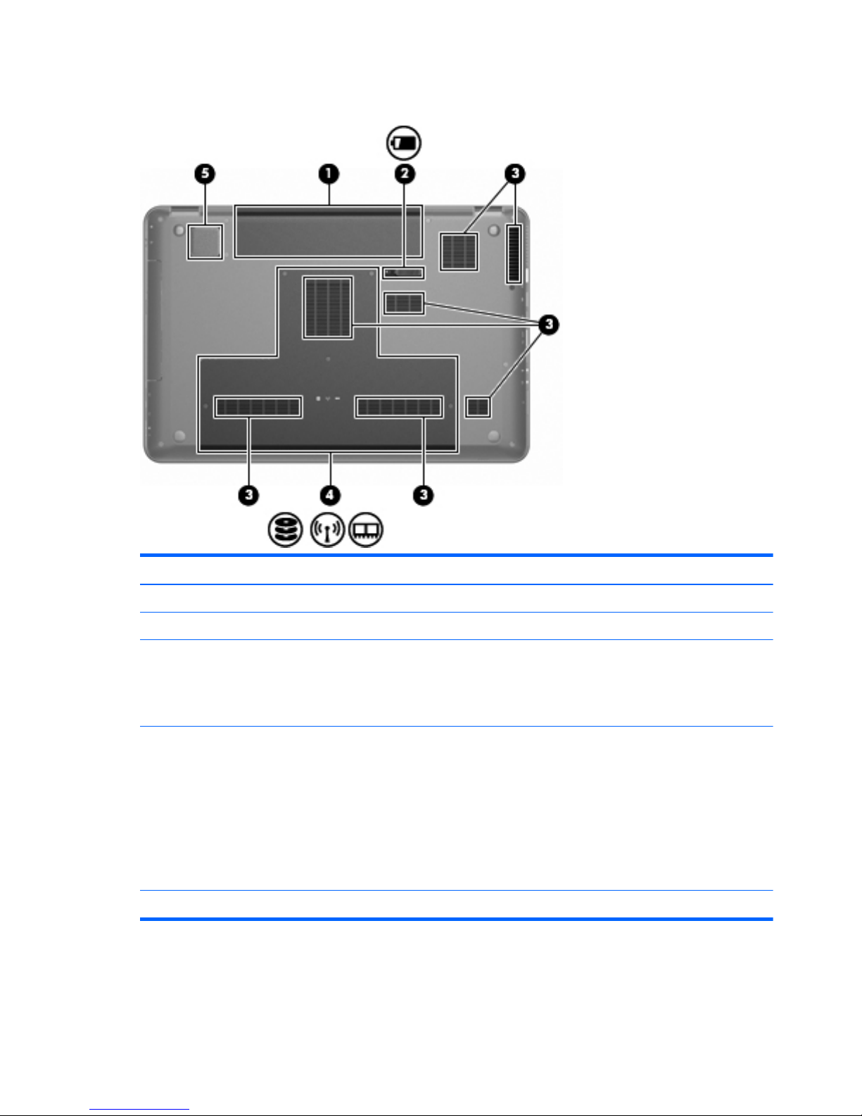
Bottom components
Item Description Function
1 Battery bay Holds the battery.
2 Battery Release latch Releases the battery from the battery bay.
3 Vents (7) Enable airflow to cool internal components.
NOTE: The computer fan starts up automatically to cool internal
components and prevent overheating. It is normal for the internal
fan to cycle on and off during routine operation.
4 Primary Hard Drive bay Holds the primary hard drive, the memory module, and the WLAN
module (select models only).
CAUTION: To prevent an unresponsive system, replace the
wireless module with a wireless module authorized for use by the
governmental agency that regulates wireless devices in your
country or region. If you replace the module and then receive a
warning message, remove the module to restore computer
functionality, and then contact technical support through Help and
Support.
5 Integrated subwoofer Provides superior bass sound.
14 Chapter 2 Components
Page 23
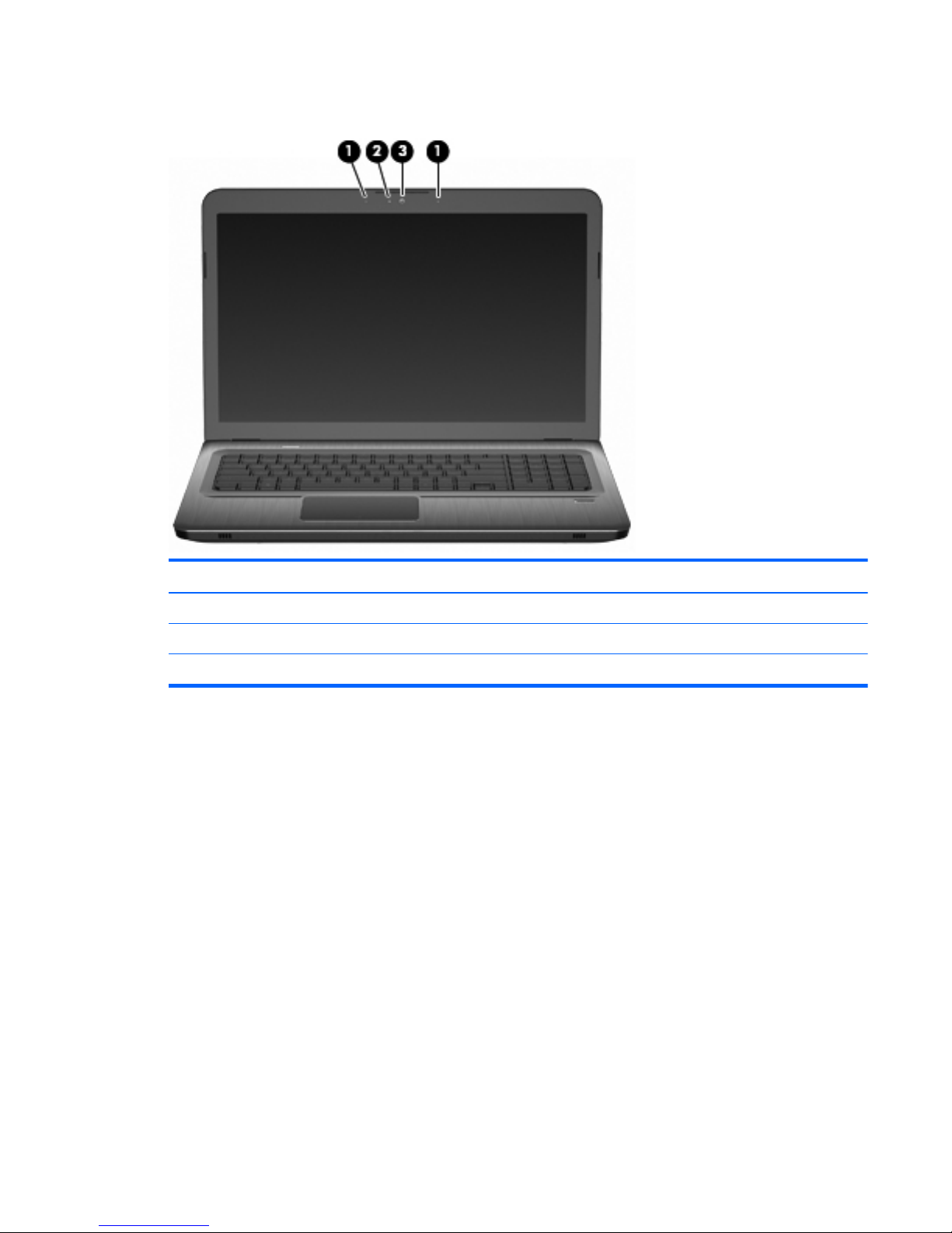
Display components
Item Description Function
1 Internal microphones (2) Record sound.
2 Webcam light On—The webcam is in use.
3 Webcam Records video, and captures still photographs.
Display components
15
Page 24
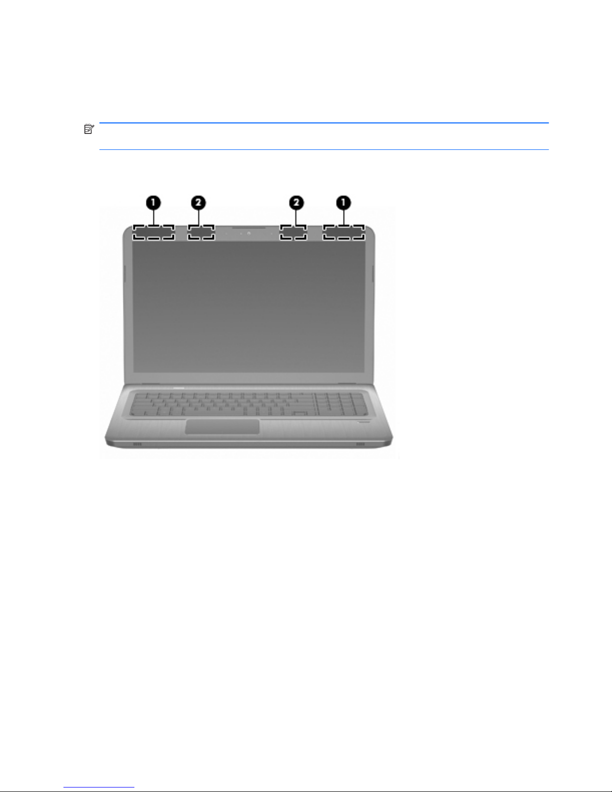
Wireless antennas (select models only)
On select computer models, at least two antennas (1, 2) send and receive signals from one or more
wireless devices. These antennas are not visible from the outside of the computer.
NOTE: For optimal transmission, keep the areas immediately around the antennas free from
obstructions.
To review wireless regulatory notices, see the country-specific section of the Regulatory, Safety and
Environmental Notices chapter in Help and Support.
16 Chapter 2 Components
Page 25
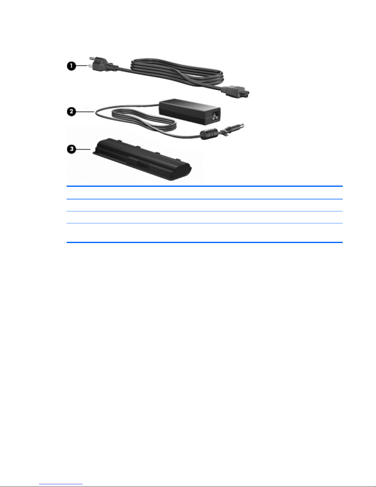
Additional hardware components
Item Description Function
1 Power cord* Connects an AC adapter to an AC outlet.
2 AC adapter Converts AC power to DC power.
3 Battery* Provides power when the computer is not connected to an external
power source.
* Batteries and power cords vary in appearance by region and country.
Additional hardware components
17
Page 26

3 Illustrated parts catalog
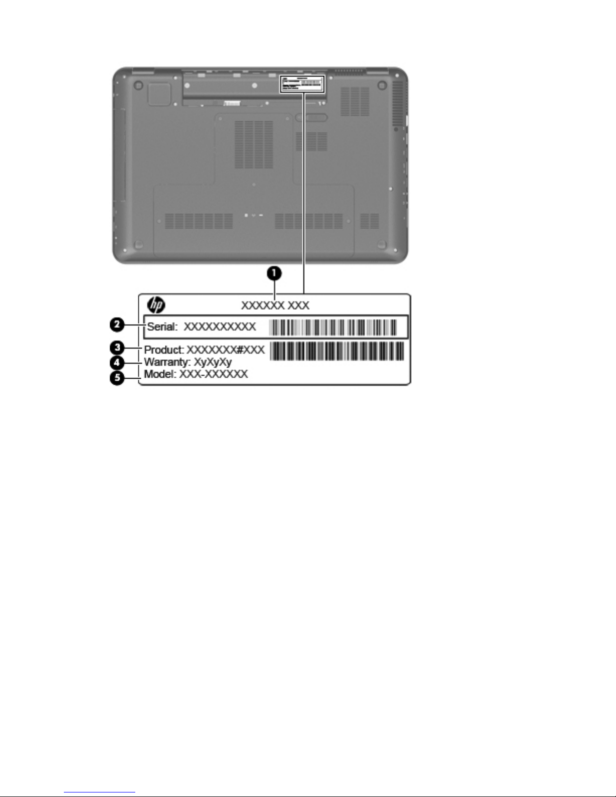
Service tag
When ordering parts or requesting information, provide the computer serial number and model
description provided on the service tag.
(1) Product name: This is the product name affixed to the front of the computer.
(2) Serial number (s/n): This is an alphanumeric identifier that is unique to each product.
(3) Part number/Product number (p/n): This number provides specific information about the product's
hardware components. The part number helps a service technician to determine what components and
parts are needed.
(4) Warranty period: This number describes the duration of the warranty period for the computer.
(5) Model description: This is the alphanumeric identifier needed to locate documents, drivers, and
support for the computer.
18 Chapter 3 Illustrated parts catalog
Page 27
Service tag
19
Page 28
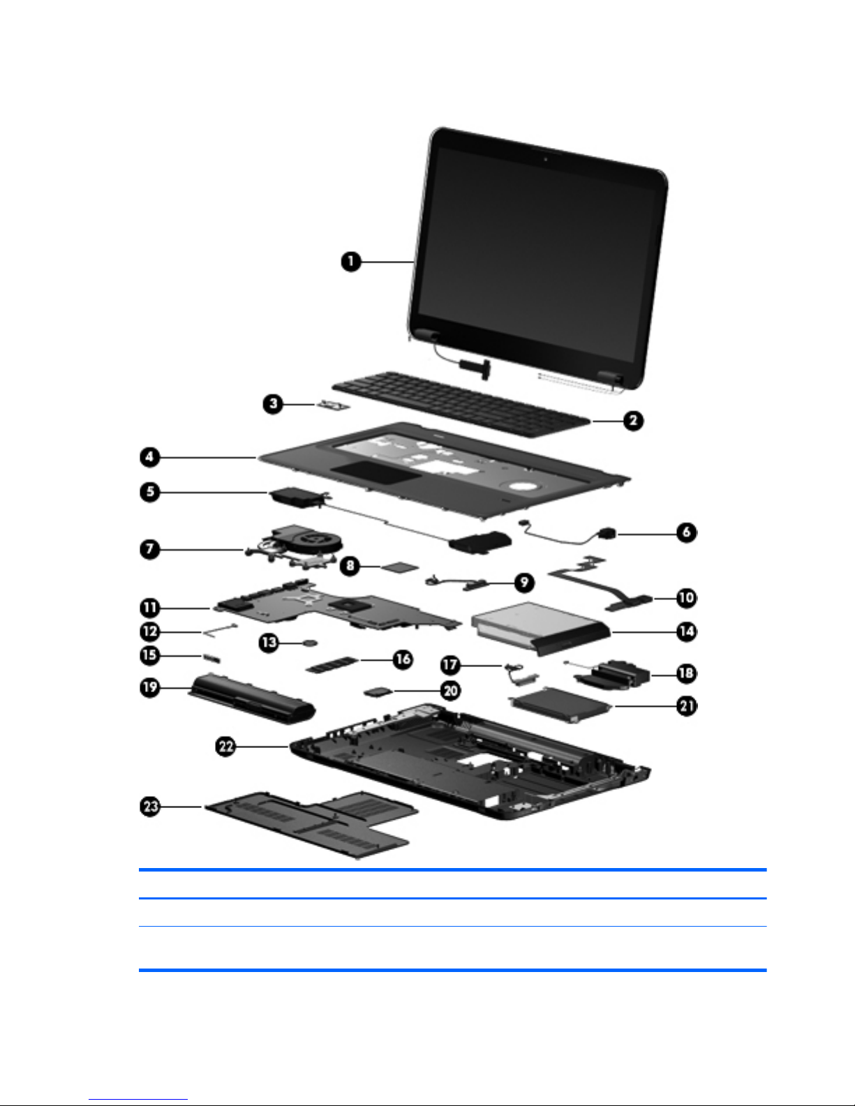
Computer major components
Item Description Spare part number
(1) 17.3-in display assembly
HD+ BrightView display assembly with webcam and 2 microphones for use in silver
computers
605324-001
20 Chapter 3 Illustrated parts catalog
Page 29

Item Description Spare part number
HD+ flush glass AntiGlare display assembly with webcam and 2 microphones for use
in silver computers
605325-001
HD+ BrightView display assembly with webcam and 2 microphones for use in black
computers
605327-001
HD+ Brightview display assembly with webcam and 2 microphones for use in white
computers
609788-001
NOTE: See
Display assembly components on page 26 for more information on display assembly spare part
numbers.
(2) Keyboard (includes keyboard cable)
NOTE: For a detailed list of available keyboards, see
Sequential part number
listing on page 32.
605344-xxx
(3) Power button board (includes cable) 605358-001
(4) Top cover (includes TouchPad and TouchPad buttons)
For use only with silver computer models equipped with a fingerprint reader, and
includes a fingerprint reader board
605346-001
For use only with black computer models not equipped with a fingerprint reader 605347-001
For use only with white computer models not equipped with a fingerprint reader 609789-001
(5) Speaker assembly 605356-001
(6) Power connector and cable 605364-001
(7) Fan/heat sink assembly (includes replacement thermal material)
For use only with computer models equipped with graphics subsystems with UMA
memory
603690-001
For use only with computer models equipped with ATI Mobility Radeon HD 5470
graphics subsystems with discrete memory
604787-001
For use only with computer models equipped with ATI Mobility Radeon HD 5650
graphics subsystems with discrete memory
603691-001
(8) Processor (includes replacement thermal material)
Intel Core i7-820QM processor with 1.73-GHz, SC turbo up to 3.06-GHz, Quad
45W (select models only)
583053-001
Intel Core i7-720QM processor with 1.6-GHz, SC turbo up to 2.8-GHz, Dual 45W
(select models only)
586170-001
Intel Core i5-540M processor with 2.53-GHz, SC turbo up to 3.06-GHz, Dual 35W 594188-001
Intel Core i5-520M processor with 2.4-GHz, SC turbo up to 2.93-GHz, Dual 35W 594187-001
Intel Core i5-430M processor with 2.26-GHz, SC turbo up to 2.53-GHz, Dual 35W 597624-001
Intel Core i3 350M processor 2.26-GHz, Dual 35W 597623-001
(9) Optical drive connector 603680-001
(10) USB board (includes cable) 605348-001
Computer major components
21
Page 30

Item Description Spare part number
(11) System board (includes replacement thermal material)
With ATI Mobility Radeon HD 5470 discrete graphics subsystem and 512-MB of
dedicated memory (Dual Core) and subwoofer
609787-001
With ATI Mobility Radeon HD 5650 discrete graphics subsystem and 1-GB of
dedicated memory (Quad core) and subwoofer
615307-001
With ATI Mobility Radeon HD 5650 discrete graphics subsystem and 1-GB of
dedicated memory (Dual core) and subwoofer
615308-001
With ATI Mobility Radeon HD 5470 discrete graphics subsystem and 512-MB of
dedicated memory (Dual Core)
605319-001
With ATI Mobility Radeon HD 5650 discrete graphics subsystem and 1-GB of
dedicated memory (Quad core)
605320-001
With ATI Mobility Radeon HD 5650 discrete graphics subsystem and 1-GB of
dedicated memory (Dual core)
605321-001
With Intel HM55 HD UMA graphics subsystem and shared memory 605322-001
(12) Bluetooth module cable 605323-001
(13) RTC battery 599516-001
(14) Optical drive (includes bezel and bracket):
DVD±RW and CD-RW SuperMulti Double-Layer Combo Drive with LightScribe 605416-001
Blu-ray ROM with LightScribe DVD±R/RW SuperMulti DL Drive 605417–001
(15) Bluetooth® module (does not include a Bluetooth module cable) 537921-001
(16) Memory modules DDR3, 1333-MHz
1-GB memory module 598859-001
2-GB memory module 598856-001
4-GB memory module 599092-001
(17) Hard drive cable 605415-001
(18) Subwoofer 605357-001
(19) Battery
6-cell, 55-Wh, 2.55-Ah Li-ion battery for use with all computer models 593554-001
6-cell, 62-Wh, 2.8-Ah Li-ion battery for use with all computer models 593562-001
9-cell, 93-Wh, 2.8-Ah Li-ion battery for use with all computer models 593550-001
(20) WLAN module
22 Chapter 3 Illustrated parts catalog
Page 31

Item Description Spare part number
Atheros AR9285 802.11b/g/n module for use in Afghanistan, Albania, Algeria,
Andorra, Angola, Antigua and Barbuda, Argentina, Armenia, Aruba, Australia,
Austria, Azerbaijan, Bahamas, Bahrain, Bangladesh, Barbados, Belarus, Belgium,
Belize, Benin, Bermuda, Bhutan, Bolivia, Bosnia and Herzegovina, Botswana, Brazil,
British Virgin Islands, Brunei, Bulgaria, Burkina Faso, Burundi, Cambodia, Cameroon,
Cayman Islands, Canada, Cape Verde, Central African Republic, Chad, Chile,
People's Republic of China, Colombia, Comoros, Congo, Costa Rica, Croatia,
Cyprus, Czech Republic, Denmark, Djibouti, Dominica, Dominican Republic, East
Timor, Ecuador, Egypt, El Salvador, Equitorial Guinea, Eritrea, Estonia, Ethiopia, Fiji,
Finland, France, French Guiana, Gabon, Gambia, Georgia, Germany, Ghana,
Gibraltar, Greece, Grenada, Guadeloupe, Guatemala, Guinea, Guinea-Bissau,
Guam, Guyana, Haiti, Honduras, Hong Kong, Hungary, Iceland, India, Indonesia,
Ireland, Israel, Italy, Ivory Coast, Jamaica, Japan, Jordan, Kazakhstan, Kenya,
Kiribati, Kuwait, Kyrgyzstan, Laos, Latvia, Lebanon, Lesotho, Liberia, Liechtenstein,
Lithuania, Luxembourg, Macedonia, Madagascar, Malawi, Malaysia, Maldives,
Mali, Malta, Marshall Islands, Martinique, Mauritania, Mauritius, Mexico,
Micronesia, Monaco, Mongolia, Montenegro, Morocco, Mozambique, Namibia,
Nauru, Nepal, Nether Antilles, Netherlands, New Zealand, Nicaragua, Niger,
Nigeria, Norway, Oman, Pakistan, Palau, Panama, Papua New Guinea, Paraguay,
Peru, Philippines, Poland, Portugal, Puerto Rico, Qatar, Republic of Moldova,
Romania, Russia, Rwanda, Samoa, San Marino, Sao Tome and Principe, Saudi
Arabia, Senegal, Serbia, Seychelles, Sierra Leone, Singapore, Slovakia, Slovenia,
Solomon Islands, Somalia, South Africa, South Korea, Spain, Sri Lanka, St. Kitts and
Nevis, St. Lucia, St. Vincent and Gren, Suriname, Swaziland, Sweden, Switzerland,
Taiwan, Tajikistan, Tanzania, Thailand, Togo, Tonga, Trinidad and Tobago, Tunisia,
Turkey, Turkmenistan, Tuvalu, Uganda, Ukraine, United Arab Emirates, United
Kingdom, Uruguay, the United States, Uzbekistan, US Virgin Islands, Vanuatu,
Venezuela, Vietnam, Yemen, Zaire, Zambia, Zimbabwe
605560-005
Broadcom 4322 802.11a/b/g/n WLAN module for use in Antigua and Barbuda,
Aruba, Bahamas, Barbados, Belize, Canada, Guinea, Haiti, Jamaica, Guam, Nether
Antilles, Puerto Rico, St. Kitts and Nevis, St. Lucia, St. Vincent and Grenadines,
Suriname, and the United States
582564-001
Computer major components
23
Page 32

Item Description Spare part number
Broadcom 4322 802.11a/b/g/n WLAN module for use in Afghanistan, Albania,
Algeria, Andorra, Angola, Argentina, Armenia, Australia, Austria, Azerbaijan,
Bahrain, Belarus, Belgium, Benin, Bermuda, Bhutan, Bolivia, Bosnia and
Herzegovina, Botswana, Brazil, British Virgin Islands, Brunei, Bulgaria, Burkina Faso,
Burundi, Cambodia, Cameroon, Cape Verde, Cayman Islands, Central African
Republic, Chad, Chile, People's Republic of China, Colombia, Comoros, Congo,
Costa Rica, Croatia, Cyprus, Czech Republic, Zaire, Denmark, Djibouti, Dominica,
Dominican Republic, East Timor, Ecuador, Egypt, El Salvador, Equitorial Guinea,
Eritrea, Estonia, Ethiopia, Fiji, Finland, France, French Guiana, Gabon, Gambia,
Georgia, Germany, Ghana, Gibraltar, Greece, Grenada, Guadeloupe, Guatemala,
Guinea-Bissau, Guyana, Honduras, Hong Kong, Hungary, Iceland, India, Ireland,
Italy, Ivory Coast, Japan, Jordan, Kazakhstan, Kenya, Kiribati, Kuwait, Kyrgyzstan,
Laos, Latvia, Lebanon, Lesotho, Liberia, Liechtenstein, Lithuania, Luxembourg,
Macedonia, Madagascar, Malawi, Malaysia, Maldives, Mali, Malta, Marshall
Islands, Martinique, Mauritania, Mauritius, Mexico, Micronesia, Monaco, Mongolia,
Montenegro, Morocco, Mozambique, Namibia, Nauru, Nepal, Netherlands, New
Zealand, Nicaragua, Niger, Nigeria, Norway, Oman, Palau, Panama, Papua New
Guinea, Paraguay, Peru, Philippines, Poland, Portugal, Qatar, Republic of Moldova,
Romania, Rwanda, Samoa, San Marino, Sao Tome and Principe, Saudi Arabia,
Senegal, Serbia, Seychelles, Sierra Leone, Singapore, Slovakia, Slovenia, Solomon
Islands, Somalia, South Africa, South Korea, Spain, Sri Lanka, Swaziland, Sweden,
Switzerland, Taiwan, Tajikistan, Tanzania, Thailand, Togo, Tonga, Trinidad and
Tobago, Tunisia, Turkey, Turkmenistan, Tuvalu, Uganda, United Arab Emirates,
United Kingdom, Uruguay, Uzbekistan, Vanuatu, Venezuela, Vietnam, Yemen,
Zambia, Zimbabwe
582564-002
Intel 1000 802.11b/g/n WLAN module for use in Andorra, Antigua, Barbuda,
Argentina, Australia, Austria, Azerbaijan, Bahamas, Bahrain, Barbados, Belgium,
Bolivia, Bosnia and Herzegovina, Brazil, Brunei, Bulgaria, Canada, Chile, People's
Republic of China, Colombia, Costa Rica, Croatia, Cyprus, Czech Republic,
Denmark, Dominican Republic, Ecuador, Egypt, El Salvador, Estonia, Finland,
France, Georgia, Germany, Ghana, Greece, Guatemala, Haiti, Honduras, Hong
Kong, Hungary, Iceland, India, Indonesia, Ireland, Israel, Italy, Ivory Coast, Jamaica,
Japan, Jordan, Kenya, South Korea, Kuwait, Kyrgyzstan, Latvia, Lebanon, Nether
Antilles, Martinique, Guadeloupe, French Guiana, Cayman Islands, Bermuda, Aruba,
Puerto Rico, Guam, US Virgin Islands, Liechtenstein, Lithuania, Luxembourg, Malawi,
Malaysia, Malta, Mauritius, Mexico, Monaco, Montenegro, Morocco, Netherlands,
New Zealand, Nicaragua, Nigeria, Norway, Oman, Pakistan, Panama, Paraguay,
Peru, Philippines, Poland, Portugal, Qatar, Romania, San Marino, Saudi Arabia,
Senegal, Serbia, Singapore, Slovakia, Slovenia, South Africa, Spain, Sri Lanka,
Sweden, Switzerland, Taiwan, Tanzania, Thailand, Trinidad and Tobago, Turkey,
Ukraine, United Arab Emirates, United Kingdom, Uruguay, USA, Venezuela, Vietnam
593530-001
24 Chapter 3 Illustrated parts catalog
Page 33

Item Description Spare part number
Broadcom BCM94313 802.11b/g/n WLAN module for use in Afghanistan,
Albania, Algeria, Andorra, Angola, Antigua and Barbuda, Argentina, Armenia,
Aruba, Australia, Austria, Azerbaijan, Bahamas, Bahrain, Bangladesh, Barbados,
Belarus, Belgium, Belize, Benin, Bermuda, Bhutan, Bolivia, Bosnia and Herzegovina,
Botswana, Brazil, British Virgin Islands, Brunei, Bulgaria, Burkina Faso, Burundi,
Cambodia, Cameroon, Canada, Cape Verde, Central African Republic, Chad,
Cayman Islands, Chile, People's Republic of China Colombia, Comoros, Congo,
Costa Rica, Croatia, Cyprus, Czech Republic, Denmark, Djibouti, Dominica,
Dominican Republic, East Timor, Ecuador, Egypt, El Salvador, Equitorial Guinea,
Eritrea, Estonia, Ethiopia, Fiji, Finland, France, French Guiana, Gabon, Gambia,
Georgia, Germany, Ghana, Gibraltar, Greece, Grenada, Guadeloupe, Guam,
Guatemala, Guinea, Guinea-Bissau, Guyana, Haiti, Honduras, Hong Kong,
Hungary, Iceland, India, Indonesia, Iraq, Ireland, Israel, Italy, Ivory Coast, Jamaica,
Japan, Jordan, Kazakhstan, Kenya, Kiribati, Kuwait, Kyrgyzstan, Laos, Latvia,
Lebanon, Lesotho, Liberia, Liechtenstein, Lithuania, Luxembourg, Macedonia,
Madagascar, Malawi, Malaysia, Maldives, Mali, Malta, Marshall Islands,
Martinique, Mauritania, Mauritius, Mexico, Micronesia, Monaco, Mongolia,
Montenegro, Morocco, Mozambique, Namibia, Nauru, Nepal, Netherlands, Nether
Antilles, New Zealand, Nicaragua, Niger, Nigeria, Norway, Oman, Pakistan,
Palau, Panama, Papua New Guinea, Paraguay, Peru, Philippines, Poland, Portugal,
Puerto Rico, Qatar, Republic of Moldova, Romania, Russia, Rwanda, Samoa, San
Marino, Sao Tome and Principe, Saudi Arabia, Senegal, Serbia, Seychelles, Sierra
Leone, Singapore, Slovakia, Slovenia, Solomon Islands, Somalia, South Africa, South
Korea, Spain, Sri Lanka, St. Kitts and Nevis, St. Lucia, St. Vincent and Grenadines,
Suriname, Swaziland, Sweden, Switzerland, Syria, Taiwan, Tajikistan, Tanzania,
Thailand, Togo, Tonga, Trinidad and Tobago, Tunisia, Turkey, Turkmenistan, Tuvalu,
Uganda, Ukraine, United Arab Emirates, United Kingdom, Uruguay, USA,
Uzbekistan, US Virgin Islands, Vanuatu, Venezuela, Vietnam, Yemen, Zaire, Zambia,
Zimbabwe
593836-001
(21) Hard drive (includes left and right bracket rails, connector cable, Mylar cover with tab, and 4 rubber isolators)
1-TB, 5200-rpm (select models only) 616747-001
750-GB, 5200-rpm (select models only) 616746-001
640-GB, 5400-rpm 603785-001
500-GB, 7200-rpm 603784-001
320-GB, 7200-rpm 603783-001
250-GB, 7200-rpm 605606-001
160-GB solid-state drive (SSD) 603781-001
Hard Drive Hardware Kit (not illustrated, includes left and right bracket rails,
connector cable, Mylar cover with tab, and 4 rubber isolators)
605415-001
(22) Base enclosure (includes rubber feet) 605345-001
Base enclosure for use with silver computer models (includes rubber feet) 615443-001
(23) Primary hard drive cover 605360-001
Computer major components
25
Page 34

Display assembly components
Flush glass display assembly spare parts
Item Description Spare part number
(1) Display enclosure (includes wireless antenna transceivers and cables and logo LED
board and cable)
605330-001
(2) Webcam/microphone module 603660-001
(3) Display Hinge Kit (includes right and left hinges) 605334-001
(4) Flush glass display assembly (includes display panel cable) 605325-001
(5) Display Cable Kit (includes display panel cable, and Webcam cable) 605333-001
(6) Display hinge cover 605336-001
Display Screw Kit (not illustrated) 611251-001
26 Chapter 3 Illustrated parts catalog
Page 35

BrightView panel
Item Description Spare part number
(1) Display bezel
For use in silver computer models 605340-001
For use in all other computer models 615442-001
(2) Display hinge cover 605343-001
(3) Display Hinge Kit (includes left and right hinges) 605342-001
(4) Display panel (includes display panel cable) 605337-001
(5) Webcam/microphone module 605335-001
(6) Display Cable Kit (includes display panel cable and Webcam cable) 605333-001
(7) Wireless antenna (select models only) 605359-001
(8) Display enclosure
For use in silver computers 605338-001
Display assembly components
27
Page 36

Item Description Spare part number
For use in white computers 605339-001
For use in black computers 605331-001
Display Rubber Kit (not illustrated, includes display bezel rubber screw covers) 605341-001
Display Screw Kit (not illustrated) 605332-001
28 Chapter 3 Illustrated parts catalog
Page 37

Mass storage devices
Item Description Spare part number
(1) Optical drive (includes bezel and bracket)
Blu-ray ROM with LightScribe DVD±R/RW SuperMulti DL Drive 605417-001
DVD±RW and CD-RW SuperMulti Double-Layer Combo Drive with LightScribe 605416-001
(2) Hard drive (includes left and right bracket rails, connector cable, Mylar cover with tab, and 4 rubber isolators):
●
1-TB, 5200-rpm (select models only) 616747-001
●
750-GB, 5200-rpm (select models only) 616746-001
●
640-GB, 5400-rpm 603785-001
●
500-GB, 7200-rpm 603784-001
●
320-GB, 7200-rpm 603783-001
●
250-GB, 7200-rpm 605606-001
●
160-GB, SSD 603781-001
Hard Drive Hardware Kit (not illustrated, includes left and right bracket rails,
connector cable, Mylar cover with tab, and 4 rubber isolators)
605415-001
Mass storage devices
29
Page 38

Miscellaneous parts
Description Spare part number
AC adapters
65-W AC adapter 609939-001
65-W AC adapter PFC 609948-001
90-W AC adapter PFC 609947-001
90-W AC adapter PFC 609940-001
120-W AC adapter PFC 609941-001
Power cords:
Australia and New Zealand 490371-011
Belgium, Bulgaria, the Czech Republic, Finland, France, Germany, Greece, Hungary, Iceland,
the Netherlands, northwest Africa, Norway, Poland, Portugal, Russia, Slovakia, Spain, Sweden,
and Turkey
490371-021
Asia/Pacific region, French Canada, Latin America, Thailand, and the United States 490371-001
Brazil 490371-201
Denmark 490371-081
India 490371-D61
Israel 490371-BB1
Italy 490371-061
Japan 490371-291
South Africa 490371-AR1
South Korea 490371-AD1
Switzerland 490371-111
Taiwan 490371-AB1
The United Kingdom and Hong Kong 490371-031
Full-function remote control with teletext 465541-003
Rubber feet 605644-001
DVB-T TV tuner 581222-001
30 Chapter 3 Illustrated parts catalog
Page 39

Description Spare part number
DVB-T antenna 581223-001
Screw Kit
●
Phillips PM2.5×6.5 screw
●
Phillips PM2.5×5.0 screw
●
Phillips PM2.5×4.0 screw
●
Phillips PM2.5×3.0 screw
●
Phillips PM2.5×1.5 screw
●
Phillips PM2.0×3.0 screw
●
Phillips PM2.0×1.5 screw
605643-001
Miscellaneous parts
31
Page 40

Sequential part number listing
Spare part
number
Description
465541-003 Full-function remote control with teletext
490371-001 Power cord for use in the Asia/Pacific region, French Canada, Latin America, Thailand, and the United
States
490371-011 Power cord for use in Australia and New Zealand
490371-021 Power cord for use in Belgium, Bulgaria, the Czech Republic, Finland, France, Germany, Greece,
Hungary, Iceland, the Netherlands, northwest Africa, Norway, Poland, Portugal, Russia, Slovakia, Spain,
Sweden, and Turkey
490371-031 Power cord for use in the United Kingdom and Hong Kong
490371-061 Power cord for use in Italy
490371-081 Power cord for use in Denmark
490371-111 Power cord for use in Switzerland
490371-201 Power cord for use in Brazil
490371-291 Power cord for use in Japan
490371-AB1 Power cord for use in the Taiwan
490371-AD1 Power cord for use in South Korea
490371-AR1 Power cord for use in South Africa
490371-BB1 Power cord for use in Israel
490371-D61 Power cord for use in India
537921-001 Bluetooth module (does not include a Bluetooth module cable)
581222-001 TV tuner, DVB-T
581223-001 Antenna, DVB-T
582564-001 Broadcom 4322 802.11a/b/g/n WLAN module for use in Antigua and Barbuda, Aruba, Bahamas,
Barbados, Belize, Canada, Guinea, Haiti, Jamaica, Guam, Nether Antilles, Puerto Rico, St. Kitts and
Nevis, St. Lucia, St. Vincent and Grenadines, Suriname, and the United States
32 Chapter 3 Illustrated parts catalog
Page 41

Spare part
number
Description
582564-002 Broadcom 4322 802.11a/b/g/n WLAN module for use in Afghanistan, Albania, Algeria, Andorra,
Angola, Argentina, Armenia, Australia, Austria, Azerbaijan, Bahrain, Belarus, Belgium, Benin, Bermuda,
Bhutan, Bolivia, Bosnia and Herzegovina, Botswana, Brazil, British Virgin Islands, Brunei, Bulgaria,
Burkina Faso, Burundi, Cambodia, Cameroon, Cape Verde, Cayman Islands, Central African Republic,
Chad, Chile, People's Republic of China, Colombia, Comoros, Congo, Costa Rica, Croatia, Cyprus,
Czech Republic, Zaire, Denmark, Djibouti, Dominica, Dominican Republic, East Timor, Ecuador, Egypt, El
Salvador, Equitorial Guinea, Eritrea, Estonia, Ethiopia, Fiji, Finland, France, French Guiana, Gabon,
Gambia, Georgia, Germany, Ghana, Gibraltar, Greece, Grenada, Guadeloupe, Guatemala, GuineaBissau, Guyana, Honduras, Hong Kong, Hungary, Iceland, India, Ireland, Italy, Ivory Coast, Japan,
Jordan, Kazakhstan, Kenya, Kiribati, Kuwait, Kyrgyzstan, Laos, Latvia, Lebanon, Lesotho, Liberia,
Liechtenstein, Lithuania, Luxembourg, Macedonia, Madagascar, Malawi, Malaysia, Maldives, Mali,
Malta, Marshall Islands, Martinique, Mauritania, Mauritius, Mexico, Micronesia, Monaco, Mongolia,
Montenegro, Morocco, Mozambique, Namibia, Nauru, Nepal, Netherlands, New Zealand, Nicaragua,
Niger, Nigeria, Norway, Oman, Palau, Panama, Papua New Guinea, Paraguay, Peru, Philippines,
Poland, Portugal, Qatar, Republic of Moldova, Romania, Rwanda, Samoa, San Marino, Sao Tome and
Principe, Saudi Arabia, Senegal, Serbia, Seychelles, Sierra Leone, Singapore, Slovakia, Slovenia,
Solomon Islands, Somalia, South Africa, South Korea, Spain, Sri Lanka, Swaziland, Sweden, Switzerland,
Taiwan, Tajikistan, Tanzania, Thailand, Togo, Tonga, Trinidad and Tobago, Tunisia, Turkey,
Turkmenistan, Tuvalu, Uganda, United Arab Emirates, United Kingdom, Uruguay, Uzbekistan, Vanuatu,
Venezuela, Vietnam, Yemen, Zambia, Zimbabwe
583053-001 Intel Core i7 820QM processor with 1.73-GHz, SC turbo up to 3.06-GHz, Quad 45W (select models
only)
586170-001 Intel Core i7 720QM processor with 1.6-GHz, SC turbo up to 2.8-GHz, Dual 45W (select models only)
593530-001 Intel 1000 802.11b/g/n WLAN module for use in Andorra, Antigua, Barbuda, Argentina, Australia,
Austria, Azerbaijan, Bahamas, Bahrain, Barbados, Belgium, Bolivia, Bosnia and Herzegovina, Brazil,
Brunei, Bulgaria, Canada, Chile, People's Republic of China, Colombia, Costa Rica, Croatia, Cyprus,
Czech Republic, Denmark, Dominican Republic, Ecuador, Egypt, El Salvador, Estonia, Finland, France,
Georgia, Germany, Ghana, Greece, Guatemala, Haiti, Honduras, Hong Kong, Hungary, Iceland, India,
Indonesia, Ireland, Israel, Italy, Ivory Coast, Jamaica, Japan, Jordan, Kenya, South Korea, Kuwait,
Kyrgyzstan, Latvia, Lebanon, Nether Antilles, Martinique, Guadeloupe, French Guiana, Cayman Islands,
Bermuda, Aruba, Puerto Rico, Guam, US Virgin Islands, Liechtenstein, Lithuania, Luxembourg, Malawi,
Malaysia, Malta, Mauritius, Mexico, Monaco, Montenegro, Morocco, Netherlands, New Zealand,
Nicaragua, Nigeria, Norway, Oman, Pakistan, Panama, Paraguay, Peru, Philippines, Poland, Portugal,
Qatar, Romania, San Marino, Saudi Arabia, Senegal, Serbia, Singapore, Slovakia, Slovenia, South
Africa, Spain, Sri Lanka, Sweden, Switzerland, Taiwan, Tanzania, Thailand, Trinidad and Tobago,
Turkey, Ukraine, United Arab Emirates, United Kingdom, Uruguay, USA, Venezuela, Vietnam
593550-001 9-cell, 93-Wh, 2.8-Ah Li-ion battery for use with all computer models
593554-001 6-cell, 55-Wh, 2.55-Ah Li-ion battery for use with all computer models
593562-001 6-cell, 62-Wh, 2.8-Ah Li-ion battery for use with all computer models
Sequential part number listing
33
Page 42

Spare part
number
Description
593836-001 Broadcom BCM94313 802.11b/g/n WLAN module for use in Afghanistan, Albania, Algeria, Andorra,
Angola, Antigua and Barbuda, Argentina, Armenia, Aruba, Australia, Austria, Azerbaijan, Bahamas,
Bahrain, Bangladesh, Barbados, Belarus, Belgium, Belize, Benin, Bermuda, Bhutan, Bolivia, Bosnia and
Herzegovina, Botswana, Brazil, British Virgin Islands, Brunei, Bulgaria, Burkina Faso, Burundi, Cambodia,
Cameroon, Canada, Cape Verde, Central African Republic, Chad, Cayman Islands, Chile, People's
Republic of China Colombia, Comoros, Congo, Costa Rica, Croatia, Cyprus, Czech Republic, Denmark,
Djibouti, Dominica, Dominican Republic, East Timor, Ecuador, Egypt, El Salvador, Equitorial Guinea,
Eritrea, Estonia, Ethiopia, Fiji, Finland, France, French Guiana, Gabon, Gambia, Georgia, Germany,
Ghana, Gibraltar, Greece, Grenada, Guadeloupe, Guam, Guatemala, Guinea, Guinea-Bissau, Guyana,
Haiti, Honduras, Hong Kong, Hungary, Iceland, India, Indonesia, Iraq, Ireland, Israel, Italy, Ivory Coast,
Jamaica, Japan, Jordan, Kazakhstan, Kenya, Kiribati, Kuwait, Kyrgyzstan, Laos, Latvia, Lebanon, Lesotho,
Liberia, Liechtenstein, Lithuania, Luxembourg, Macedonia, Madagascar, Malawi, Malaysia, Maldives,
Mali, Malta, Marshall Islands, Martinique, Mauritania, Mauritius, Mexico, Micronesia, Monaco,
Mongolia, Montenegro, Morocco, Mozambique, Namibia, Nauru, Nepal, Netherlands, Nether Antilles,
New Zealand, Nicaragua, Niger, Nigeria, Norway, Oman, Pakistan, Palau, Panama, Papua New
Guinea, Paraguay, Peru, Philippines, Poland, Portugal, Puerto Rico, Qatar, Republic of Moldova,
Romania, Russia, Rwanda, Samoa, San Marino, Sao Tome and Principe, Saudi Arabia, Senegal, Serbia,
Seychelles, Sierra Leone, Singapore, Slovakia, Slovenia, Solomon Islands, Somalia, South Africa, South
Korea, Spain, Sri Lanka, St. Kitts and Nevis, St. Lucia, St. Vincent and Grenadines, Suriname, Swaziland,
Sweden, Switzerland, Syria, Taiwan, Tajikistan, Tanzania, Thailand, Togo, Tonga, Trinidad and Tobago,
Tunisia, Turkey, Turkmenistan, Tuvalu, Uganda, Ukraine, United Arab Emirates, United Kingdom,
Uruguay, USA, Uzbekistan, US Virgin Islands, Vanuatu, Venezuela, Vietnam, Yemen, Zaire, Zambia,
Zimbabwe
594187-001 Intel Core i5 520M processor with 2.4-GHz, SC turbo up to 2.93-GHz, Dual 35W
594188-001 Intel Core i5 540M processor with 2.53-GH, SC turbo up to 3.06-GHz, Dual 35W
597623-001 Intel Core i3 350M processor with 2.26-GHz, Dual 35W
597624-001 Intel Core i5 430M processor with 2.26-GHz, SC turbo up to 2.53-GHz, Dual 35W
598856-001 2-GB memory module
598859-001 1-GB memory module
599092-001 4-GB memory module
599516-001 RTC battery
603660-001 Webcam/microphone module
603680-001 Optical drive cable
603690-001 Fan/heat sink assembly for use only with computer models equipped with graphics subsystems with UMA
memory (includes replacement thermal material)
603691-001 Fan/heat sink assembly for use only with computer models equipped with graphics subsystems with
discrete memory (includes replacement thermal material)
603781-001 160-GB solid-state drive (SSD)
603783-001 320-GB, 7200-rpm hard drive (includes left and right bracket rails, connector cable, Mylar cover with tab,
and 4 rubber isolators)
603784-001 500-GB, 7200-rpm hard drive (includes left and right bracket rails, connector cable, Mylar cover with tab,
and 4 rubber isolators)
34 Chapter 3 Illustrated parts catalog
Page 43

Spare part
number
Description
603785-001 640-GB, 5400-rpm hard drive (includes left and right bracket rails, connector cable, Mylar cover with tab,
and 4 rubber isolators)
604787-001 Fan/heat sink assembly for use only with computer models equipped with discrete memory
605319-001 System board for ATI Mobility Radeon HD 5470 discrete graphics subsystem and 512-MB of dedicated
memory (Dual Core)
605320-001 System board for ATI Mobility Radeon HD 5650 discrete graphics subsystem and 1-GB of dedicated
memory (Quad core)
605321-001 System board for ATI Mobility Radeon HD 5650 discrete graphics subsystem and 1-GB of dedicated
memory (Dual core)
605322-001 System board for Intel HM55 HD UMA graphics subsystem and shared memory
605323-001 Bluetooth module cable
605324-001 17.3-inch HD+ BrightView display assembly with webcam and 2 microphones for use in silver computers
(includes wireless antenna transceivers and cables)
605325-001 17.3-inch HD+ flush glass AntiGlare display assembly with webcam and 2 microphones for use in silver
computers
605327-001 17.3-inch HD+ BrightView display assembly with webcam and 2 microphones for use in black computers
605330-001 Display enclosure for use with flush glass displays in silver computers (includes wireless antenna
transceivers and cables and logo LED board and cable)
605331-001 Display enclosure for use with BrightView displays in black computers (includes wireless antenna
transceivers and cables and logo LED board and cable)
605332-001 Display Screw Kit
605333-001 Display Cable Kit (includes display panel cable, and Webcam cable)
605334-001 Display Hinge Kit (includes right and left hinges) for use with flush glass displays
605336-001 Display hinge cover for use with flush glass displays
605337-001 BrightView display panel (includes display panel cable)
605338-001 Display enclosure for use in silver computer models with BrightView displays (includes wireless antenna
transceivers and cables and logo LED board and cable)
605339-001 Display enclosure for use in white computer models with BrightView displays (includes wireless antenna
transceivers and cables and logo LED board and cable)
605340-001 Display bezel for use with BrightView displays
605341-001 Display Rubber Kit (not illustrated, includes display bezel rubber screw covers)
605342-001 Display Hinge Kit (includes left and right hinges) for BrightView displays
605343-001 Display hinge cover for BrightView displays
605344-001 Keyboard for use in the United States
605344-031 Keyboard for use in the United Kingdom
605344-041 Keyboard for use in Germany
Sequential part number listing
35
Page 44

Spare part
number
Description
605344-051 Keyboard for use in France
605344-061 Keyboard for use in Italy
605344-071 Keyboard for use in Spain
605344-121 Keyboard for use in French Canada
605344-131 Keyboard for use in Portugal
605344-141 Keyboard for use in Turkey
605344-171 Keyboard for use in Saudi Arabia
605344-211 Keyboard for use in Hungary
605344-221 Keyboard for use in the Czech Republic
605344-251 Keyboard for use in Russia
605344-281 Keyboard for use in Thailand
605344-291 Keyboard for use in Japan
605344-A41 Keyboard for use in Belgium
605344-AB1 Keyboard for use in Taiwan
605344-AD1 Keyboard for use in South Korea
605344-B31 Keyboard for use internationally
605334-BA1 Keyboard for use Slovenia
605344-BB1 Keyboard for use in white computers in Israel
605344-BG1 Keyboard for use in Switzerland
605344-DH1 Keyboard for use in Denmark, Norway, and Sweden
605344-DJ1 Keyboard for use in Greece
605345-001 Base enclosure (includes rubber feet)
605346-001 Top cover for use only with silver computer models equipped with a fingerprint reader; and includes
fingerprint reader board (includes TouchPad and TouchPad buttons)
605347-001 Top cover for use only with black computer models not equipped with a fingerprint reader
605348-001 USB board (includes cable)
605356-001 Speaker assembly
605357-001 Subwoofer
605358-001 Power button board (includes cable)
605359-001 Wireless antenna
605360-001 Plastic Kit
605364-001 Power connector and cable
36 Chapter 3 Illustrated parts catalog
Page 45

Spare part
number
Description
605415-001 Hard Drive Hardware Kit (not illustrated, includes left and right bracket rails, connector cable, Mylar cover
with tab, and 4 rubber isolators)
605416-001 DVD±RW and CD-RW SuperMulti Double-Layer Combo Drive with LightScribe
605417-001 Blu-ray ROM with LightScribe DVD±R/RW SuperMulti DL Drive
605560-005 Atheros AR9285 802.11b/g/n module for use in Afghanistan, Albania, Algeria, Andorra, Angola,
Antigua and Barbuda, Argentina, Armenia, Aruba, Australia, Austria, Azerbaijan, Bahamas, Bahrain,
Bangladesh, Barbados, Belarus, Belgium, Belize, Benin, Bermuda, Bhutan, Bolivia, Bosnia and
Herzegovina, Botswana, Brazil, British Virgin Islands, Brunei, Bulgaria, Burkina Faso, Burundi, Cambodia,
Cameroon, Cayman Islands, Canada, Cape Verde, Central African Republic, Chad, Chile, People's
Republic of China, Colombia, Comoros, Congo, Costa Rica, Croatia, Cyprus, Czech Republic, Denmark,
Djibouti, Dominica, Dominican Republic, East Timor, Ecuador, Egypt, El Salvador, Equitorial Guinea,
Eritrea, Estonia, Ethiopia, Fiji, Finland, France, French Guiana, Gabon, Gambia, Georgia, Germany,
Ghana, Gibraltar, Greece, Grenada, Guadeloupe, Guatemala, Guinea, Guinea-Bissau, Guam, Guyana,
Haiti, Honduras, Hong Kong, Hungary, Iceland, India, Indonesia, Ireland, Israel, Italy, Ivory Coast,
Jamaica, Japan, Jordan, Kazakhstan, Kenya, Kiribati, Kuwait, Kyrgyzstan, Laos, Latvia, Lebanon, Lesotho,
Liberia, Liechtenstein, Lithuania, Luxembourg, Macedonia, Madagascar, Malawi, Malaysia, Maldives,
Mali, Malta, Marshall Islands, Martinique, Mauritania, Mauritius, Mexico, Micronesia, Monaco,
Mongolia, Montenegro, Morocco, Mozambique, Namibia, Nauru, Nepal, Nether Antilles, Netherlands,
New Zealand, Nicaragua, Niger, Nigeria, Norway, Oman, Pakistan, Palau, Panama, Papua New
Guinea, Paraguay, Peru, Philippines, Poland, Portugal, Puerto Rico, Qatar, Republic of Moldova,
Romania, Russia, Rwanda, Samoa, San Marino, Sao Tome and Principe, Saudi Arabia, Senegal, Serbia,
Seychelles, Sierra Leone, Singapore, Slovakia, Slovenia, Solomon Islands, Somalia, South Africa, South
Korea, Spain, Sri Lanka, St. Kitts and Nevis, St. Lucia, St. Vincent and Gren, Suriname, Swaziland,
Sweden, Switzerland, Taiwan, Tajikistan, Tanzania, Thailand, Togo, Tonga, Trinidad and Tobago,
Tunisia, Turkey, Turkmenistan, Tuvalu, Uganda, Ukraine, United Arab Emirates, United Kingdom,
Uruguay, the United States, Uzbekistan, US Virgin Islands, Vanuatu, Venezuela, Vietnam, Yemen, Zaire,
Zambia, Zimbabwe
605606-001 250-GB, 7200-rpm hard drive (includes left and right bracket rails, connector cable, Mylar cover with tab,
and 4 rubber isolators)
605643-001 Screw kit
605644-001 Rubber feet
609787-001 System board for ATI Mobility Radeon HD 5470 discrete graphics subsystem and 512-MB of dedicated
memory (Dual Core) and subwoofer
609788-001 17.3-inch HD+ BrightView display assembly with webcam and 2 microphones for use in white computers
609789-001 Top cover for use only with white computer models not equipped with a fingerprint reader
609939-001 65-W AC adapter
609940-001 90-W AC adapter
609941-001 120-W AC adapter PFC
609947-001 90-W AC adapter PFC
609948-001 65-W AC adapter PFC
611251-001 Display Screw Kit for Flush glass display
615307-001 System board for ATI Mobility Radeon HD 5650 discrete graphics subsystem and 1-GB of dedicated
memory (Quad core) and subwoofer
Sequential part number listing
37
Page 46

Spare part
number
Description
615308-001 System board for ATI Mobility Radeon HD 5650 discrete graphics subsystem and 1-GB of dedicated
memory (Dual core) and subwoofer
615442-001 Display bezel for BrightView display assemblies
615443-001 Base enclosure (includes rubber feet) for use only with silver computer models
616746-001 750-GB, 5200-rpm hard drive (includes left and right bracket rails, connector cable, Mylar cover with tab,
and 4 rubber isolators)
616747-001 1-TB, 5200-rpm hard drive (includes left and right bracket rails, connector cable, Mylar cover with tab,
and 4 rubber isolators)
38 Chapter 3 Illustrated parts catalog
Page 47

4 Removal and replacement
procedures
Preliminary replacement requirements
Tools required
You will need the following tools to complete the removal and replacement procedures:
●
Magnetic screwdriver
●
Phillips P0 and P1 screwdrivers
●
Flat-bladed screwdriver
Service considerations
The following sections include some of the considerations that you must keep in mind during
disassembly and assembly procedures.
NOTE: As you remove each subassembly from the computer, place the subassembly (and all
accompanying screws) away from the work area to prevent damage.
Plastic parts
CAUTION: Using excessive force during disassembly and reassembly can damage plastic parts. Use
care when handling the plastic parts. Apply pressure only at the points designated in the maintenance
instructions.
Preliminary replacement requirements
39
Page 48

Cables and connectors
CAUTION: When servicing the computer, be sure that cables are placed in their proper locations
during the reassembly process. Improper cable placement can damage the computer.
Cables must be handled with extreme care to avoid damage. Apply only the tension required to unseat
or seat the cables during removal and insertion. Handle cables by the connector whenever possible. In
all cases, avoid bending, twisting, or tearing cables. Be sure that cables are routed in such a way that
they cannot be caught or snagged by parts being removed or replaced. Handle flex cables with
extreme care; these cables tear easily.
Drive handling
CAUTION: Drives are fragile components that must be handled with care. To prevent damage to the
computer, damage to a drive, or loss of information, observe these precautions:
Before removing or inserting a hard drive, shut down the computer. If you are unsure whether the
computer is off or in Hibernation, turn the computer on, and then shut it down through the operating
system.
Before handling a drive, be sure that you are discharged of static electricity. While handling a drive,
avoid touching the connector.
Before removing a diskette drive or optical drive, be sure that a diskette or disc is not in the drive and
be sure that the optical drive tray is closed.
Handle drives on surfaces covered with at least one inch of shock-proof foam.
Avoid dropping drives from any height onto any surface.
After removing a hard drive, an optical drive, or a diskette drive, place it in a static-proof bag.
Avoid exposing a hard drive to products that have magnetic fields, such as monitors or speakers.
Avoid exposing a drive to temperature extremes or liquids.
If a drive must be mailed, place the drive in a bubble pack mailer or other suitable form of protective
packaging and label the package “FRAGILE.”
40 Chapter 4 Removal and replacement procedures
Page 49

Grounding guidelines
Electrostatic discharge damage
Electronic components are sensitive to electrostatic discharge (ESD). Circuitry design and structure
determine the degree of sensitivity. Networks built into many integrated circuits provide some
protection, but in many cases, ESD contains enough power to alter device parameters or melt
silicon junctions.
A discharge of static electricity from a finger or other conductor can destroy static-sensitive devices or
microcircuitry. Even if the spark is neither felt nor heard, damage may have occurred.
An electronic device exposed to ESD may not be affected at all and can work perfectly throughout a
normal cycle. Or the device may function normally for a while, then degrade in the internal layers,
reducing its life expectancy.
CAUTION: To prevent damage to the computer when you are removing or installing internal
components, observe these precautions:
Keep components in their electrostatic-safe containers until you are ready to install them.
Use nonmagnetic tools.
Before touching an electronic component, discharge static electricity by using the guidelines described
in this section.
Avoid touching pins, leads, and circuitry. Handle electronic components as little as possible.
If you remove a component, place it in an electrostatic-safe container.
The following table shows how humidity affects the electrostatic voltage levels generated by different
activities.
CAUTION: A product can be degraded by as little as 700 V.
Typical electrostatic voltage levels
Relative humidity
Event 10% 40% 55%
Walking across carpet 35,000 V 15,000 V 7,500 V
Walking across vinyl floor 12,000 V 5,000 V 3,000 V
Motions of bench worker 6,000 V 800 V 400 V
Removing DIPS from plastic tube 2,000 V 700 V 400 V
Removing DIPS from vinyl tray 11,500 V 4,000 V 2,000 V
Removing DIPS from Styrofoam 14,500 V 5,000 V 3,500 V
Removing bubble pack from PCB 26,500 V 20,000 V 7,000 V
Packing PCBs in foam-lined box 21,000 V 11,000 V 5,000 V
Preliminary replacement requirements
41
Page 50

Packaging and transporting guidelines
Follow these grounding guidelines when packaging and transporting equipment:
●
To avoid hand contact, transport products in static-safe tubes, bags, or boxes.
●
Protect ESD-sensitive parts and assemblies with conductive or approved containers or packaging.
●
Keep ESD-sensitive parts in their containers until the parts arrive at static-free workstations.
●
Place items on a grounded surface before removing items from their containers.
●
Always be properly grounded when touching a component or assembly.
●
Store reusable ESD-sensitive parts from assemblies in protective packaging or nonconductive
foam.
●
Use transporters and conveyors made of antistatic belts and roller bushings. Be sure that
mechanized equipment used for moving materials is wired to ground and that proper materials
are selected to avoid static charging. When grounding is not possible, use an ionizer to dissipate
electric charges.
Workstation guidelines
Follow these grounding workstation guidelines:
●
Cover the workstation with approved static-shielding material.
●
Use a wrist strap connected to a properly grounded work surface and use properly grounded tools
and equipment.
●
Use conductive field service tools, such as cutters, screwdrivers, and vacuums.
●
When fixtures must directly contact dissipative surfaces, use fixtures made only of static-safe
materials.
●
Keep the work area free of nonconductive materials, such as ordinary plastic assembly aids and
Styrofoam.
●
Handle ESD-sensitive components, parts, and assemblies by the case or PCM laminate. Handle
these items only at static-free workstations.
●
Avoid contact with pins, leads, or circuitry.
●
Turn off power and input signals before inserting or removing connectors or test equipment.
42 Chapter 4 Removal and replacement procedures
Page 51

Equipment guidelines
Grounding equipment must include either a wrist strap or a foot strap at a grounded workstation.
●
When seated, wear a wrist strap connected to a grounded system. Wrist straps are flexible straps
with a minimum of one megohm ±10% resistance in the ground cords. To provide proper ground,
wear a strap snugly against the skin at all times. On grounded mats with banana-plug connectors,
use alligator clips to connect a wrist strap.
●
When standing, use foot straps and a grounded floor mat. Foot straps (heel, toe, or boot straps)
can be used at standing workstations and are compatible with most types of shoes or boots. On
conductive floors or dissipative floor mats, use foot straps on both feet with a minimum of one
megohm resistance between the operator and ground. To be effective, the conductive strips must
be worn in contact with the skin.
The following grounding equipment is recommended to prevent electrostatic damage:
●
Antistatic tape
●
Antistatic smocks, aprons, and sleeve protectors
●
Conductive bins and other assembly or soldering aids
●
Nonconductive foam
●
Conductive tabletop workstations with ground cords of one megohm resistance
●
Static-dissipative tables or floor mats with hard ties to the ground
●
Field service kits
●
Static awareness labels
●
Material-handling packages
●
Nonconductive plastic bags, tubes, or boxes
●
Metal tote boxes
●
Electrostatic voltage levels and protective materials
The following table lists the shielding protection provided by antistatic bags and floor mats.
Material Use Voltage protection level
Antistatic plastic Bags 1,500 V
Carbon-loaded plastic Floor mats 7,500 V
Metallized laminate Floor mats 5,000 V
Preliminary replacement requirements
43
Page 52

Component replacement procedures
This chapter provides removal and replacement procedures.
There are as many as 78 screws, in 13 different sizes, that must be removed, replaced, or loosened
when servicing the computer. Make special note of each screw size and location during removal and
replacement.
Service tag
When ordering parts or requesting information, provide the computer serial number and model
description provided on the service tag.
(1) Product name: This is the product name affixed to the front of the computer.
(2) Serial number (s/n): This is an alphanumeric identifier that is unique to each product.
(3) Part number/Product number (p/n): This number provides specific information about the product's
hardware components. The part number helps a service technician to determine what components and
parts are needed.
(4) Warranty period: This number describes the duration of the warranty period for the computer.
(5) Model description: This is the alphanumeric identifier needed to locate documents, drivers, and
support for the computer.
44 Chapter 4 Removal and replacement procedures
Page 53

Computer feet
The computer feet are adhesive-backed rubber pads. The feet are included in the Rubber Feet Kit, spare
part number 605644-001. There are 4 rubber feet that attach to the base enclosure in the locations
illustrated below.
Component replacement procedures
45
Page 54

Battery
Description Spare part number
6-cell, 55-Wh, 2.55-Ah Li-ion battery for use with all computer models 593554-001
6-cell, 62-Wh, 2.8-Ah Li-ion battery for use with all computer models 593562-001
9-cell, 93-Wh, 2.8-Ah Li-ion battery for use with all computer models 593550-001
Before disassembling the computer, follow these steps:
1. Shut down the computer. If you are unsure whether the computer is off or in Hibernation, turn the
computer on, and then shut it down through the operating system.
2. Disconnect all external devices connected to the computer.
3. Disconnect the power from the computer by first unplugging the power cord from the AC outlet
and then unplugging the AC adapter from the computer.
Remove the battery:
1. Turn the computer upside down on a flat surface.
2. Slide the battery release latch (1) to release the battery.
3. Pivot the battery (2) upward and remove it from the computer (3).
To insert the battery, insert the rear edge of the battery into the battery bay and pivot the front edge of
the battery downward until it is seated. The battery release latch automatically locks the battery into
place.
46 Chapter 4 Removal and replacement procedures
Page 55

Primary hard drive cover
Description Spare part number
Primary hard drive cover 605360-001
Before removing the primary hard drive cover, follow these steps:
1. Shut down the computer. If you are unsure whether the computer is off or in Hibernation, turn the
computer on, and then shut it down through the operating system.
2. Disconnect all external devices connected to the computer.
3. Disconnect the power from the computer by first unplugging the power cord from the AC outlet
and then unplugging the AC adapter from the computer.
4. Remove the battery (see
Battery on page 46).
Remove the primary hard drive cover:
1. Loosen the five Phillips PM2.5×6.0 captive screws (1) that secure the primary hard drive cover to
the computer.
2. Lift the primary hard drive cover (2) away from the computer.
Reverse this procedure to install the primary hard drive cover.
Component replacement procedures
47
Page 56

Hard drive
NOTE: The hard drive spare part kit includes left and right bracket rails, a connector cable, Mylar
cover with tab, and 4 rubber isolators.
Description Spare part number
1-TB, 5200-rpm (select models only) 616747-001
750-GB, 5200-rpm (select moldels only) 646746-001
640-GB, 5400-rpm 603785-001
500-GB, 7200-rpm 603784-001
320-GB, 7200-rpm 603783-001
250-GB, 7200-rpm 605606-001
160-GB, SSD 603781-001
Hard Drive Hardware Kit (includes left and right bracket rails, connector cable, Mylar cover with
tab, and 4 rubber isolators)
605415-001
Before removing the hard drive, follow these steps:
1. Shut down the computer. If you are unsure whether the computer is off or in Hibernation, turn the
computer on, and then shut it down through the operating system.
2. Disconnect all external devices connected to the computer.
3. Disconnect the power from the computer by first unplugging the power cord from the AC outlet
and then unplugging the AC adapter from the computer.
4. Remove the battery (see
Battery on page 46).
5. Remove the primary hard drive cover (see
Primary hard drive cover on page 47).
Remove the hard drive:
1. Remove the four Phillips PM2.5×3.0 screws (1).
48 Chapter 4 Removal and replacement procedures
Page 57

2.
Disconnect the hard drive by sliding it to the left (2), and then remove the hard drive (3) from the
computer.
3. If it is necessary to replace the hard drive bracket or any of the hard drive bracket components,
remove the following:
●
(1) Hard drive adapter cable
●
(2) Four rubber isolators
●
(3) Four Phillips PM3.0×3.5 screws that secure the hard drive bracket rails and Mylar cover
to the hard drive
●
(4) Left and right hard drive bracket rails with Mylar cover
Component replacement procedures
49
Page 58

Reverse this procedure to install the hard drive.
Secondary hard drive
NOTE: The hard drive spare part kit includes left and right bracket rails, a connector cable, Mylar
cover with tab, and 4 rubber isolators.
Description Spare part number
1-TB, 5200-rpm (select models only) 616747-001
750-GB, 5200-rpm (select models only) 616746-001
640-GB, 5400-rpm 603785-001
500-GB, 7200-rpm 603784-001
320-GB, 7200-rpm 603783-001
250-GB, 7200-rpm 605606-001
160-GB, SSD 603781-001
Before removing the hard drive, follow these steps:
1. Shut down the computer. If you are unsure whether the computer is off or in Hibernation, turn the
computer on, and then shut it down through the operating system.
2. Disconnect all external devices connected to the computer.
3. Disconnect the power from the computer by first unplugging the power cord from the AC outlet
and then unplugging the AC adapter from the computer.
4. Remove the battery (see
Battery on page 46).
5. Remove the primary hard drive cover (see
Primary hard drive cover on page 47).
50 Chapter 4 Removal and replacement procedures
Page 59

Remove the secondary hard drive:
1. Remove the four hard drive screws (1).
2. Disconnect the hard drive by sliding it to the left (2), and then remove the hard drive (3) from the
computer.
Reverse this procedure to install the secondary hard drive.
Component replacement procedures
51
Page 60

WLAN module
Description Spare part number
Atheros AR9285 802.11b/g/n module for use in Afghanistan, Albania, Algeria, Andorra,
Angola, Antigua and Barbuda, Argentina, Armenia, Aruba, Australia, Austria, Azerbaijan,
Bahamas, Bahrain, Bangladesh, Barbados, Belarus, Belgium, Belize, Benin, Bermuda, Bhutan,
Bolivia, Bosnia and Herzegovina, Botswana, Brazil, British Virgin Islands, Brunei, Bulgaria,
Burkina Faso, Burundi, Cambodia, Cameroon, Cayman Islands, Canada, Cape Verde, Central
African Republic, Chad, Chile, People's Republic of China, Colombia, Comoros, Congo, Costa
Rica, Croatia, Cyprus, Czech Republic, Denmark, Djibouti, Dominica, Dominican Republic, East
Timor, Ecuador, Egypt, El Salvador, Equitorial Guinea, Eritrea, Estonia, Ethiopia, Fiji, Finland,
France, French Guiana, Gabon, Gambia, Georgia, Germany, Ghana, Gibraltar, Greece,
Grenada, Guadeloupe, Guatemala, Guinea, Guinea-Bissau, Guam, Guyana, Haiti, Honduras,
Hong Kong, Hungary, Iceland, India, Indonesia, Ireland, Israel, Italy, Ivory Coast, Jamaica,
Japan, Jordan, Kazakhstan, Kenya, Kiribati, Kuwait, Kyrgyzstan, Laos, Latvia, Lebanon, Lesotho,
Liberia, Liechtenstein, Lithuania, Luxembourg, Macedonia, Madagascar, Malawi, Malaysia,
Maldives, Mali, Malta, Marshall Islands, Martinique, Mauritania, Mauritius, Mexico, Micronesia,
Monaco, Mongolia, Montenegro, Morocco, Mozambique, Namibia, Nauru, Nepal, Nether
Antilles, Netherlands, New Zealand, Nicaragua, Niger, Nigeria, Norway, Oman, Pakistan,
Palau, Panama, Papua New Guinea, Paraguay, Peru, Philippines, Poland, Portugal, Puerto Rico,
Qatar, Republic of Moldova, Romania, Russia, Rwanda, Samoa, San Marino, Sao Tome and
Principe, Saudi Arabia, Senegal, Serbia, Seychelles, Sierra Leone, Singapore, Slovakia,
Slovenia, Solomon Islands, Somalia, South Africa, South Korea, Spain, Sri Lanka, St. Kitts and
Nevis, St. Lucia, St. Vincent and Gren, Suriname, Swaziland, Sweden, Switzerland, Taiwan,
Tajikistan, Tanzania, Thailand, Togo, Tonga, Trinidad and Tobago, Tunisia, Turkey,
Turkmenistan, Tuvalu, Uganda, Ukraine, United Arab Emirates, United Kingdom, Uruguay, the
United States, Uzbekistan, US Virgin Islands, Vanuatu, Venezuela, Vietnam, Yemen, Zaire,
Zambia, Zimbabwe
605560-005
Broadcom 4322 802.11a/b/g/n WLAN module for use in Antigua and Barbuda, Aruba,
Bahamas, Barbados, Belize, Canada, Guinea, Haiti, Jamaica, Guam, Nether Antilles, Puerto
Rico, St. Kitts and Nevis, St. Lucia, St. Vincent and Grenadines, Suriname, and the United States
582564-001
Broadcom 4322 802.11a/b/g/n WLAN module for use in Afghanistan, Albania, Algeria,
Andorra, Angola, Argentina, Armenia, Australia, Austria, Azerbaijan, Bahrain, Belarus, Belgium,
Benin, Bermuda, Bhutan, Bolivia, Bosnia & Herzegovina, Botswana, Brazil, British Virgin Islands,
Brunei, Bulgaria, Burkina Faso, Burundi, Cambodia, Cameroon, Cape Verde, Cayman Islands,
Central African Republic, Chad, Chile, People's Republic of China, Colombia, Comoros, Congo,
Costa Rica, Croatia, Cyprus, Czech Republic, Zaire, Denmark, Djibouti, Dominica, Dominican
Republic, East Timor, Ecuador, Egypt, El Salvador, Equitorial Guinea, Eritrea, Estonia, Ethiopia,
Fiji, Finland, France, French Guiana, Gabon, Gambia, Georgia, Germany, Ghana, Gibraltar,
Greece, Grenada, Guadeloupe, Guatemala, Guinea-Bissau, Guyana, Honduras, Hong Kong,
Hungary, Iceland, India, Ireland, Italy, Ivory Coast, Japan, Jordan, Kazakhstan, Kenya, Kiribati,
Kuwait, Kyrgyzstan, Laos, Latvia, Lebanon, Lesotho, Liberia, Liechtenstein, Lithuania, Luxembourg,
Macedonia, Madagascar, Malawi, Malaysia, Maldives, Mali, Malta, Marshall Islands,
Martinique, Mauritania, Mauritius, Mexico, Micronesia, Monaco, Mongolia, Montenegro,
Morocco, Mozambique, Namibia, Nauru, Nepal, Netherlands, New Zealand, Nicaragua,
Niger, Nigeria, Norway, Oman, Palau, Panama, Papua New Guinea, Paraguay, Peru,
Philippines, Poland, Portugal, Qatar, Republic of Moldova, Romania, Rwanda, Samoa, San
Marino, Sao Tome and Principe, Saudi Arabia, Senegal, Serbia, Seychelles, Sierra Leone,
Singapore, Slovakia, Slovenia, Solomon Islands, Somalia, South Africa, South Korea, Spain, Sri
Lanka, Swaziland, Sweden, Switzerland, Taiwan, Tajikistan, Tanzania, Thailand, Togo, Tonga,
Trinidad and Tobago, Tunisia, Turkey, Turkmenistan, Tuvalu, Uganda, United Arab Emirates,
United Kingdom, Uruguay, Uzbekistan, Vanuatu, Venezuela, Vietnam, Yemen, Zambia,
Zimbabwe
582564-002
52 Chapter 4 Removal and replacement procedures
Page 61

Description Spare part number
Intel 1000 802.11b/g/n WLAN module for use in Andorra, Antigua, Barbuda, Argentina,
Australia, Austria, Azerbaijan, Bahamas, Bahrain, Barbados, Belgium, Bolivia, Bosnia and
Herzegovina, Brazil, Brunei, Bulgaria, Canada, Chile, People's Republic of China, Colombia,
Costa Rica, Croatia, Cyprus, Czech Republic, Denmark, Dominican Republic, Ecuador, Egypt, El
Salvador, Estonia, Finland, France, Georgia, Germany, Ghana, Greece, Guatemala, Haiti,
Honduras, Hong Kong, Hungary, Iceland, India, Indonesia, Ireland, Israel, Italy, Ivory Coast,
Jamaica, Japan, Jordan, Kenya, South Korea, Kuwait, Kyrgyzstan, Latvia, Lebanon, Nether
Antilles, Martinique, Guadeloupe, French Guiana, Cayman Islands, Bermuda, Aruba, Puerto
Rico, Guam, US Virgin Islands, Liechtenstein, Lithuania, Luxembourg, Malawi, Malaysia, Malta,
Mauritius, Mexico, Monaco, Montenegro, Morocco, Netherlands, New Zealand, Nicaragua,
Nigeria, Norway, Oman, Pakistan, Panama, Paraguay, Peru, Philippines, Poland, Portugal,
Qatar, Romania, San Marino, Saudi Arabia, Senegal, Serbia, Singapore, Slovakia, Slovenia,
South Africa, Spain, Sri Lanka, Sweden, Switzerland, Taiwan, Tanzania, Thailand, Trinidad &
Tobago, Turkey, Ukraine, United Arab Emirates, United Kingdom, Uruguay, USA, Venezuela,
Vietnam
593530-001
Broadcom BCM94313 802.11b/g/n WLAN module for use in Afghanistan, Albania, Algeria,
Andorra, Angola, Antigua and Barbuda, Argentina, Armenia, Aruba, Australia, Austria,
Azerbaijan, Bahamas, Bahrain, Bangladesh, Barbados, Belarus, Belgium, Belize, Benin,
Bermuda, Bhutan, Bolivia, Bosnia and Herzegovina, Botswana, Brazil, British Virgin Islands,
Brunei, Bulgaria, Burkina Faso, Burundi, Cambodia, Cameroon, Canada, Cape Verde, Central
African Republic, Chad, Cayman Islands, Chile, People's Republic of China Colombia, Comoros,
Congo, Costa Rica, Croatia, Cyprus, Czech Republic, Denmark, Djibouti, Dominica, Dominican
Republic, East Timor, Ecuador, Egypt, El Salvador, Equitorial Guinea, Eritrea, Estonia, Ethiopia,
Fiji, Finland, France, French Guiana, Gabon, Gambia, Georgia, Germany, Ghana, Gibraltar,
Greece, Grenada, Guadeloupe, Guam, Guatemala, Guinea, Guinea-Bissau, Guyana, Haiti,
Honduras, Hong Kong, Hungary, Iceland, India, Indonesia, Iraq, Ireland, Israel, Italy, Ivory
Coast, Jamaica, Japan, Jordan, Kazakhstan, Kenya, Kiribati, Kuwait, Kyrgyzstan, Laos, Latvia,
Lebanon, Lesotho, Liberia, Liechtenstein, Lithuania, Luxembourg, Macedonia, Madagascar,
Malawi, Malaysia, Maldives, Mali, Malta, Marshall Islands, Martinique, Mauritania, Mauritius,
Mexico, Micronesia, Monaco, Mongolia, Montenegro, Morocco, Mozambique, Namibia,
Nauru, Nepal, Netherlands, Nether Antilles, New Zealand, Nicaragua, Niger, Nigeria,
Norway, Oman, Pakistan, Palau, Panama, Papua New Guinea, Paraguay, Peru, Philippines,
Poland, Portugal, Puerto Rico, Qatar, Republic of Moldova, Romania, Russia, Rwanda, Samoa,
San Marino, Sao Tome and Principe, Saudi Arabia, Senegal, Serbia, Seychelles, Sierra Leone,
Singapore, Slovakia, Slovenia, Solomon Islands, Somalia, South Africa, South Korea, Spain, Sri
Lanka, St. Kitts and Nevis, St. Lucia, St. Vincent and Grenadines, Suriname, Swaziland, Sweden,
Switzerland, Syria, Taiwan, Tajikistan, Tanzania, Thailand, Togo, Tonga, Trinidad and Tobago,
Tunisia, Turkey, Turkmenistan, Tuvalu, Uganda, Ukraine, United Arab Emirates, United Kingdom,
Uruguay, USA, Uzbekistan, US Virgin Islands, Vanuatu, Venezuela, Vietnam, Yemen, Zaire,
Zambia, Zimbabwe
593836-001
Before removing the WLAN module, follow these steps:
1. Shut down the computer. If you are unsure whether the computer is off or in Hibernation, turn the
computer on, and then shut it down through the operating system.
2. Disconnect all external devices connected to the computer.
3. Disconnect the power from the computer by first unplugging the power cord from the AC outlet
and then unplugging the AC adapter from the computer.
4. Remove the battery (see
Battery on page 46).
Component replacement procedures
53
Page 62

5.
Remove the primary hard drive cover (see
Primary hard drive cover on page 47).
6. Remove the primary hard drive (see
Hard drive on page 48).
Remove the WLAN module:
CAUTION: To prevent an unresponsive system, replace the wireless module only with a wireless
module authorized for use in the computer by the governmental agency that regulates wireless devices
in your country or region. If you replace the module and then receive a warning message, remove the
module to restore computer functionality, and then contact technical support through Help and Support.
1. Disconnect the WLAN antenna cables (1) from the WLAN module.
NOTE: The black WLAN antenna cable is connected to the WLAN module “Main” terminal. The
white WLAN antenna cable is connected to the WLAN module “Aux” terminal.
2. Remove the two Phillips PM2.5×3.5 screws (2) that secure the WLAN module to the computer.
(The edge of the module opposite the slot rises away from the computer.)
3. Remove the WLAN module (3) by pulling it away from the slot.
NOTE: WLAN modules are designed with a notch (4) to prevent incorrect insertion into the
WLAN module slot.
Reverse this procedure to install a WLAN module.
54 Chapter 4 Removal and replacement procedures
Page 63

RTC battery
Description Spare part number
RTC battery 599516-001
Before removing the RTC battery, follow these steps:
1. Shut down the computer. If you are unsure whether the computer is off or in Hibernation, turn the
computer on, and then shut it down through the operating system.
2. Disconnect all external devices connected to the computer.
3. Disconnect the power from the computer by first unplugging the power cord from the AC outlet
and then unplugging the AC adapter from the computer.
4. Remove the battery (see
Battery on page 46).
5. Remove the primary hard drive cover (see
Primary hard drive cover on page 47).
Remove the RTC battery:
▲
Remove the RTC battery from the socket on the system board.
Reverse this procedure to install the RTC battery. Be sure that the RTC battery is installed with the “+”
sign facing up.
Component replacement procedures
55
Page 64

Memory module
Description Spare part number
1-GB memory module 598859-001
2-GB memory module 598856-001
4-GB memory module 599092-001
Before removing the memory module, follow these steps:
1. Shut down the computer. If you are unsure whether the computer is off or in Hibernation, turn the
computer on, and then shut it down through the operating system.
2. Disconnect all external devices connected to the computer.
3. Disconnect the power from the computer by first unplugging the power cord from the AC outlet
and then unplugging the AC adapter from the computer.
4. Remove the battery (see
Battery on page 46).
5. Remove the primary hard drive cover (see
Primary hard drive cover on page 47).
Remove the memory module:
1. Spread the retaining tabs (1) on each side of the memory module slot to release the memory
module. (The edge of the module opposite the slot rises away from the computer.)
2. Remove the module (2) by pulling it away from the slot at an angle.
NOTE: Memory modules are designed with a notch to prevent incorrect insertion.
Reverse this procedure to install the memory module.
56 Chapter 4 Removal and replacement procedures
Page 65

Optical drive
NOTE: The optical drive spare part kit includes an optical drive bezel and bracket.
Description Spare part number
Blu-ray ROM with LightScribe DVD±R/RW SuperMulti DL Drive 605417-001
DVD±RW and CD-RW SuperMulti Double-Layer Combo Drive with LightScribe 605416-001
Before removing the optical drive, follow these steps:
1. Shut down the computer. If you are unsure whether the computer is off or in Hibernation, turn the
computer on, and then shut it down through the operating system.
2. Disconnect all external devices connected to the computer.
3. Disconnect the power from the computer by first unplugging the power cord from the AC outlet
and then unplugging the AC adapter from the computer.
4. Remove the battery (see
Battery on page 46).
5. Remove the primary hard drive cover (see
Primary hard drive cover on page 47).
Remove the optical drive:
1.
Position the computer with the front toward you.
2. Remove the Phillips PM2.5×3.0 screw (1) that secures the optical drive to the computer.
Component replacement procedures
57
Page 66

3.
Remove the optical drive (2).
Reverse this procedure to reassemble and install the optical drive.
Keyboard
Description Spare part number
Keyboard (includes keyboard cable)
NOTE: For a detailed list of available keyboards, see
Sequential part number listing
on page 32.
605344-xxx
Before removing the keyboard, follow these steps:
1. Shut down the computer. If you are unsure whether the computer is off or in Hibernation, turn the
computer on, and then shut it down through the operating system.
2. Disconnect all external devices connected to the computer.
3. Disconnect the power from the computer by first unplugging the power cord from the AC outlet
and then unplugging the AC adapter from the computer.
4.
Remove the battery (see
Battery on page 46).
5. Remove the primary hard drive cover (see
Primary hard drive cover on page 47).
58 Chapter 4 Removal and replacement procedures
Page 67

Remove the keyboard:
1. Remove the two Phillips PM2.5×6.5 screws (1) that secure the keyboard to the computer.
2. Slide the keyboard release switch (2) (in the battery bay) to the right.
3.
Turn the computer display-side up, with the front toward you, and open the computer as far as
possible.
4. Lift (1) and release (2) the keyboard until the keyboard connector on the system board is
accessible.
Component replacement procedures
59
Page 68

5.
Release the zero insertion force (ZIF) connector (1) to which the keyboard cable is connected and
disconnect the cable (2) from the system board.
Reverse this procedure to install the keyboard.
60 Chapter 4 Removal and replacement procedures
Page 69

Top cover
Description Spare part number
Top cover (includes TouchPad and TouchPad buttons) for use only with silver computer models
equipped with a fingerprint reader; and includes fingerprint reader board
605346-001
Top cover (includes TouchPad and TouchPad buttons) for use only with black computer models
not equipped with a fingerprint reader
605347-001
Top cover (includes TouchPad and TouchPad buttons) for use only with white computer models
not equipped with a fingerprint reader
609789-001
Before removing the top cover, follow these steps:
1. Shut down the computer. If you are unsure whether the computer is off or in Hibernation, turn the
computer on, and then shut it down through the operating system.
2. Disconnect all external devices connected to the computer.
3. Disconnect the power from the computer by first unplugging the power cord from the AC outlet
and then unplugging the AC adapter from the computer.
4. Remove the battery (see
Battery on page 46).
5. Remove the primary hard drive cover (see
Primary hard drive cover on page 47).
6. Remove the hard drive (see
Hard drive on page 48).
7. Remove the secondary hard drive (see
Secondary hard drive on page 50).
8. Remove the optical drive (see
Optical drive on page 57).
9. Remove the keyboard (see
Keyboard on page 58).
Remove the top cover:
1. Turn the computer display-side down, with the front toward you.
2. Remove the following screws:
●
4 Phillips 2.5×6.5 screws (one in each corner)
●
2 Phillips 2.5×6.5 screws (left side)
●
2 Phillips 2.5×6.5 screws (front side)
●
1 Phillips 2.5×6.5 screws (center)
●
5 Phillips 2.0×1.5 screws (in battery bay)
Component replacement procedures
61
Page 70

3. Remove the following screws:
●
3 Phillips 2.5×2.0 screws (in the optical drive bay)
●
2 Phillips 2.5×1.5 screws (in secondary hard drive bay)
●
3 Phillips 2.5×6.5 screws (battery bay)
4. Turn the computer display-side up, with the front toward you.
5. Open the computer as far as possible.
62 Chapter 4 Removal and replacement procedures
Page 71

6.
Remove 2 Phillips 2.5×6.5 screws (under keyboard).
7.
Disconnect the fingerprint reader ribbon cable (1), TouchPad ribbon cable (2), and power button
ribbon cable (3) from the system board.
Component replacement procedures
63
Page 72

8.
Lift the top cover (1) and remove from the computer (2).
Reverse this procedure to install the top cover.
64 Chapter 4 Removal and replacement procedures
Page 73

Power button board
Description Spare part number
Power button board (includes cable) 605358-001
Before removing the power button board, follow these steps:
1. Shut down the computer. If you are unsure whether the computer is off or in Hibernation, turn the
computer on, and then shut it down through the operating system.
2. Disconnect all external devices connected to the computer.
3. Disconnect the power from the computer by first unplugging the power cord from the AC outlet
and then unplugging the AC Adapter from the computer.
4. Remove the battery (see
Battery on page 46).
5. Remove the hard drive (see
Primary hard drive cover on page 47).
6. Remove the hard drive (see
Hard drive on page 48).
7. Remove the secondary hard drive (see
Secondary hard drive on page 50).
8. Remove the optical drive (see
Optical drive on page 57).
9. Remove the keyboard (see
Keyboard on page 58).
10. Remove the top cover (see
Top cover on page 61).
Remove the power button board:
1. Turn the top cover upside down with the front toward you.
2. Remove the two Phillips PM2.0×3.0 screws (1) that secure the power button board to the top
cover.
Component replacement procedures
65
Page 74

3.
Remove the power button board (2) and cable.
Reverse this procedure to install the power button board.
66 Chapter 4 Removal and replacement procedures
Page 75

Display assembly
Description Spare part number
17.3-inch HD+ BrightView display assembly with webcam and 2 microphones for use in silver
computers
605324-001
17.3-inch HD+ flush glass AntiGlare display assembly with webcam and 2 microphones for use in
silver computers
605325-001
17.3-inch HD+ BrightView display assembly with webcam and 2 microphones for use in black
computers
605327-001
17.3-inch HD+ BrightView display assembly with webcam and 2 microphones for use in white
computers
609788-001
Before removing the display assembly, follow these steps:
1.
Shut down the computer. If you are unsure whether the computer is off or in Hibernation, turn the
computer on, and then shut it down through the operating system.
2. Disconnect all external devices connected to the computer.
3. Disconnect the power from the computer by first unplugging the power cord from the AC outlet
and then unplugging the AC adapter from the computer.
4. Remove the battery (see
Battery on page 46).
5. Remove the primary hard drive cover (see
Primary hard drive cover on page 47).
6. Remove the hard drive (see
Hard drive on page 48).
7. Remove the secondary hard drive (see
Secondary hard drive on page 50).
8.
Remove the optical drive (see
Optical drive on page 57).
9. Remove the keyboard (see
Keyboard on page 58).
10.
Remove the top cover (see
Top cover on page 61).
Component replacement procedures
67
Page 76

Remove the display assembly:
1. Disconnect the WLAN cables (1) from under the system board and the display panel cable (2)
from the system board.
CAUTION: Support the display assembly when removing the following screws. Failure to
support the display assembly can result in damage to the display assembly and other computer
components.
2. Remove the two Phillips PM2.5×5.0 screws (1) that secure the display assembly to the computer.
68 Chapter 4 Removal and replacement procedures
Page 77

3.
Remove the display assembly (2).
NOTE: Steps 4 through 17 provide display assembly internal component removal information
for computer models equipped with flush glass display assemblies. See steps 18 through 29 for
display assembly internal component removal information for computer models equipped with
BrightView display assemblies.
4. If it is necessary to replace the display enclosure or any of the display assembly internal
components, remove the following screw covers and screws:
(1) Two rubber screw covers on the display bezel bottom edge. The rubber screw covers are
included in the Display Rubber Kit, spare part number 605341-001.
(2) Two Phillips PM2.5×7.0 screws.
Component replacement procedures
69
Page 78

5.
Turn the display assembly upside down, with the bottom toward you.
6. Lift and release the bottom of the display enclosure (1).
7. Disconnect the display logo cable (2) from the display panel cable.
8.
Route the webcam cable and antenna cables (3) through the hinge channel.
9.
Remove the display enclosure (4). The display enclosure is available using spare part number
605330-001.
10.
If it is necessary to remove the hinge cover, remove the four Phillips PM2.5×5.0 screws (1) that
secure the hinge cover to the display assembly, and then remove the cover (2). The hinge cover is
available using spare part number 605336-001.
11. If it is necessary to replace the webcam/microphone module, remove the Phillips PM2.0×4.0
screw (1) that secures the module to the display bezel.
12. Release the webcam/microphone module (2) as far as the webcam/microphone module cable
allows.
70 Chapter 4 Removal and replacement procedures
Page 79

13.
Disconnect the webcam/microphone module cable (3) and remove the webcam/microphone
module. The webcam/microphone module is available using spare part number 603660-001.
14. Disconnect the display panel cable from the display panel. The display panel cable is available in
the Display Cable Kit using spare part number 605333-001.
15. If it is necessary to replace the display hinges, remove the six Phillips PM2.5×5.0 screws (1) that
secure the display hinges to the top of the display panel.
16. Remove the four Phillips PM 2.0×5.0 screws that secure the hinges to the sides of the display
panel (2).
Component replacement procedures
71
Page 80

17.
Remove the display hinge assembly (3) by lifting it straight up. The Display Hinge Kit is available
using spare part number 605334-001. The Display Screw Kit is available using spare part
number 611251-001.
The left and right sides of the display hinge assembly are secured using four PM 2.5×4.0 screws
(1) to a bracket (2) as shown in the following image.
NOTE: Steps 18 through 29 provide display assembly internal component removal information
for computer models equipped with BrightView display assemblies. See steps 4 through 17 for
display assembly internal component removal information for computer models equipped with
flush glass display assemblies.
72 Chapter 4 Removal and replacement procedures
Page 81

18.
If it is necessary to replace the display bezel or any of the display assembly internal components,
remove the following screw covers and screws:
(1) Two rubber screw covers on the display bezel bottom edge. The display rubber screw covers
are included in the Display Rubber Kit, spare part number 605341-001.
(2) Two Phillips PM2.5×5.0 screws
19. Slide off each hinge cover to remove from the display assembly.
20. Flex the inside edges of the top edge (1), the left and right sides (2), and the bottom edge of the
display bezel (3) until the bezel disengages from the display enclosure.
Component replacement procedures
73
Page 82

21.
Remove the display bezel (4). The display bezel is available using the spare part number
605340-001 for silver computer models or 615442-001 all other computer models.
22.
If it is necessary to replace the display panel, remove the two Phillips PM2.5×5.0 screws from the
top corners and the six Phillips PM2.5×5.0 screws (1) from the display hinges.
23. Lift the top of the display panel (2) upward and release the display hinges.
24. Disconnect the display panel cable (3) from the back of the panel. The display panel is available
using spare part number 605337-001.
25.
If it is necessary to replace the display hinges, remove the two Phillips PM2.0×3.0 screws (1) that
secure each display hinge to the display panel.
74 Chapter 4 Removal and replacement procedures
Page 83

26.
Remove the display hinges (2). The display hinges are available in the Display Hinge Kit, spare
part 605342-001. The display hinge screws are available in the Display Screw Kit, spare part
number 605332-001.
27. If it is necessary to remove the webcam/microphone module, lift the module (1) and then
disconnect the module cable (2). The webcam/microphone module is available using spare part
number 603660-001.
Component replacement procedures
75
Page 84

28.
If it is necessary to remove the wireless antennas, remove two Phillips PM2.0×3.0 screws (1) and
lift (2) the antennas and cables to remove from the display enclosure. The wireless antennas are
available using spare part number 605359-001.
29.
If it is necessary to remove the display power panel which includes display panel cable and
Webcam cable, remove the adhesive plastic strip (1) from the display panel cable, and lift the
cable (2). Disconnect (3) the cable from the display panel and remove the cable (4). The display
panel cable is available in the Display Cable Kit using spare part number 605333-001.
Reverse this procedure to reassemble and install the display assembly.
76 Chapter 4 Removal and replacement procedures
Page 85

System board
NOTE: The system board spare kit includes replacement thermal material.
Description Spare part number
System board with ATI Mobility Radeon HD 5470 discrete graphics subsystem and 512-MB of
dedicated memory (Dual Core)
605319-001
System board with ATI Mobility Radeon HD 5470 discrete graphics subsystem and 512-MB of
dedicated memory (Dual Core) and subwoofer
609787-001
System board with ATI Mobility Radeon HD 5650 discrete graphics subsystem and 1-GB of
dedicated memory (Quad core)
605320-001
System board with ATI Mobility Radeon HD 5650 discrete graphics subsystem and 1-GB of
dedicated memory (Dual core)
605321-001
System board with Intel HM55 HD UMA graphics subsystem and shared memory 605322-001
System board with ATI Mobility Radeon HD 5650 discrete graphics subsystem and 1-GB of
dedicated memory (Quad core) and subwoofer
615307-001
System board with ATI Mobility Radeon HD 5650 discrete graphics subsystem and 1-GB of
dedicated memory (Dual core) and subwoofer
615308-001
Before removing the system board, follow these steps:
1. Shut down the computer. If you are unsure whether the computer is off or in Hibernation, turn the
computer on, and then shut it down through the operating system.
2. Disconnect all external devices connected to the computer.
3. Disconnect the power from the computer by first unplugging the power cord from the AC outlet
and then unplugging the AC adapter from the computer.
4. Remove the battery (see
Battery on page 46).
5. Remove the primary hard drive cover (see
Primary hard drive cover on page 47).
6. Remove the following components:
a. Hard drive (see
Hard drive on page 48).
b. Remove the secondary hard drive (see
Secondary hard drive on page 50).
c. Optical drive (see
Optical drive on page 57)
d. Keyboard (see
Keyboard on page 58)
e. Top cover (see
Top cover on page 61)
f. Display assembly (see
Display assembly on page 67)
Component replacement procedures
77
Page 86

When replacing the system board, be sure that the following components are removed from the
defective system board and installed on the replacement system board:
●
RTC battery (see
RTC battery on page 55)
●
Memory module (see
Memory module on page 56)
●
WLAN module (see
WLAN module on page 52)
●
Fan/heat sink assembly (see
Fan/heat sink assembly on page 87)
●
Processor (see
Processor on page 91)
Remove the system board:
1. Disconnect the following cables from the system board:
(1) USB board cable
(2) Power connector cable
(3) Subwoofer cable
(4) Speaker cable
2. Remove the two Phillips PM2.5×5.0 screws (1) that secure the system board to the base
enclosure.
78 Chapter 4 Removal and replacement procedures
Page 87

3.
Lift up on the right side of the system board until it is at approximately a 45-degree angle (2), and
then lift the system board to the right and up and out of the base enclosure (3).
Reverse this procedure to install the system board.
USB board
Description Spare part number
USB board (includes cable) 605348-001
Before removing the USB board, follow these steps:
1. Shut down the computer. If you are unsure whether the computer is off or in Hibernation, turn the
computer on, and then shut it down through the operating system.
2. Disconnect all external devices connected to the computer.
3. Disconnect the power from the computer by first unplugging the power cord from the AC outlet
and then unplugging the AC Adapter from the computer.
4.
Remove the battery (see
Battery on page 46).
5. Remove the primary hard drive cover (see
Primary hard drive cover on page 47).
6. Remove the following components:
a. Hard drive (see
Hard drive on page 48).
b. Secondary hard drive (see
Secondary hard drive on page 50).
c. Optical drive (see
Optical drive on page 57).
d. Keyboard (see
Keyboard on page 58).
Component replacement procedures
79
Page 88

e.
Top cover (see
Top cover on page 61).
f. Display assembly (see
Display assembly on page 67).
Remove the USB board:
1. Disconnect the USB board cable (1) from the LIF connector on the system board.
2. Remove the Phillips PM2.5×5.0 screw (2) that secures the USB board to the base enclosure.
3. Remove the USB board (3) from the base enclosure.
Reverse this procedure to install the USB board.
Bluetooth module
Description Spare part number
Bluetooth module (does not include cable) 537921-002
Bluetooth module cable 605323-001
Before removing the Bluetooth module, follow these steps:
1. Shut down the computer. If you are unsure whether the computer is off or in Hibernation, turn the
computer on, and then shut it down through the operating system.
2. Disconnect all external devices connected to the computer.
3. Disconnect the power from the computer by first unplugging the power cord from the AC outlet
and then unplugging the AC Adapter from the computer.
4. Remove the battery (see
Battery on page 46).
80 Chapter 4 Removal and replacement procedures
Page 89

5.
Remove the primary hard drive cover (see
Primary hard drive cover on page 47).
6. Remove the following components:
a.
Hard drive (see
Hard drive on page 48).
b. Secondary hard drive (see
Secondary hard drive on page 50).
c. Optical drive (see
Optical drive on page 57).
d. Keyboard (see
Keyboard on page 58).
e. Top cover (see
Top cover on page 61).
f. Display assembly (see
Display assembly on page 67).
Remove the Bluetooth module:
1.
Disconnect the Bluetooth module cable (1) from the system board.
2.
Slide the Bluetooth module out of the slot and remove the module (2) from the computer.
Reverse this procedure to install the Bluetooth module.
Component replacement procedures
81
Page 90

Speaker assembly
Description Spare part number
Speaker assembly 605356-001
Before removing the speaker assembly, follow these steps:
1. Shut down the computer. If you are unsure whether the computer is off or in Hibernation, turn the
computer on, and then shut it down through the operating system.
2. Disconnect all external devices connected to the computer.
3. Disconnect the power from the computer by first unplugging the power cord from the AC outlet
and then unplugging the AC adapter from the computer.
4. Remove the battery (see
Battery on page 46).
5. Remove the primary hard drive cover (see
Primary hard drive cover on page 47).
6. Remove the hard drive (see
Hard drive on page 48).
7. Remove the secondary hard drive (see
Secondary hard drive on page 50).
8. Remove the optical drive (see
Optical drive on page 57).
9. Remove the keyboard (see
Keyboard on page 58).
10. Remove the top cover (see
Top cover on page 61).
Remove the speaker assembly:
1. Disconnect the speaker assembly cable (1) from the system board.
2. Remove two Phillips PM2.5×5.0 screws (2).
82 Chapter 4 Removal and replacement procedures
Page 91

3.
Remove the speaker assembly (3).
Reverse this procedure to install the speaker assembly.
Optical drive connector
Description Spare part number
Optical drive connector 603680-001
Before removing the optical drive connector, follow these steps:
1. Shut down the computer. If you are unsure whether the computer is off or in Hibernation, turn the
computer on, and then shut it down through the operating system.
2. Disconnect all external devices connected to the computer.
3. Disconnect the power from the computer by first unplugging the power cord from the AC outlet
and then unplugging the AC adapter from the computer.
4. Remove the battery (see
Battery on page 46).
5.
Remove the primary hard drive cover (see
Primary hard drive cover on page 47).
6. Remove the following components:
a. Hard drive (see
Hard drive on page 48).
b. Secondary hard drive (see
Secondary hard drive on page 50).
c. Optical drive (see
Optical drive on page 57).
d. Keyboard (see
Keyboard on page 58).
e. Top cover (see
Top cover on page 61).
Component replacement procedures
83
Page 92

f.
Display assembly (see
Display assembly on page 67).
g. USB board (see
USB board on page 79).
Remove the optical drive connector:
1. Remove the two Phillips PM2.5×3.0 screws (1) that secure the optical drive connector to the base
enclosure.
2. Remove the optical drive connector (2) .
Reverse this procedure to install the optical drive connector.
Subwoofer
Description Spare part number
Subwoofer 605357-001
Before removing the subwoofer, follow these steps:
1. Shut down the computer. If you are unsure whether the computer is off or in Hibernation, turn the
computer on, and then shut it down through the operating system.
2.
Disconnect all external devices connected to the computer.
3.
Disconnect the power from the computer by first unplugging the power cord from the AC outlet
and then unplugging the AC adapter from the computer.
4. Remove the battery (see
Battery on page 46).
84 Chapter 4 Removal and replacement procedures
Page 93

5.
Remove the primary hard drive cover (see
Primary hard drive cover on page 47).
6. Remove the following components:
a.
Hard drive (see
Hard drive on page 48).
b. Secondary hard drive (see
Secondary hard drive on page 50).
c. Optical drive (see
Optical drive on page 57).
d. Keyboard (see
Keyboard on page 58).
e. Top cover (see
Top cover on page 61).
f. Display assembly (see
Display assembly on page 67).
g. USB board (see
USB board on page 79).
Remove the subwoofer:
1. Disconnect the subwoofer cable from the system board (1).
2. Remove the three Phillips PM2.5×4.0 broadhead screws (2) that secure the subwoofer to the base
enclosure.
3. Remove the subwoofer (3).
Reverse this procedure to install the subwoofer.
Power connector cable
Description Spare part number
Power connector and cable 605364-001
Component replacement procedures
85
Page 94

Before removing the power connector cable, follow these steps:
1. Shut down the computer. If you are unsure whether the computer is off or in Hibernation, turn the
computer on, and then shut it down through the operating system.
2. Disconnect all external devices connected to the computer.
3. Disconnect the power from the computer by first unplugging the power cord from the AC outlet
and then unplugging the AC Adapter from the computer.
4. Remove the battery (see
Battery on page 46).
5. Remove the primary hard drive cover (see
Primary hard drive cover on page 47).
6. Remove the following components:
a.
Hard drive (see
Hard drive on page 48).
b. Secondary hard drive (see
Secondary hard drive on page 50).
c.
Optical drive (see
Optical drive on page 57).
d. Keyboard (see
Keyboard on page 58).
e. Top cover (see
Top cover on page 61).
f. Display assembly (see
Display assembly on page 67).
g. System board (see
System board on page 77).
h. USB board (see
USB board on page 79).
Remove the power connector cable:
1.
Remove the Phillips PM2.5×3.0 screw (1) that secures the power connector and bracket (2) to the
base enclosure.
86 Chapter 4 Removal and replacement procedures
Page 95

2.
Remove the power connector cable (3).
Reverse this procedure to install the power connector cable.
Fan/heat sink assembly
NOTE: The fan/heat sink assembly spare kit includes replacement thermal material.
Description Spare part number
For use only with computer models equipped with graphics subsystems with UMA memory 603690-001
For use only with computer models equipped with ATI Mobility Radeon HD 5470 graphics
subsystems with discrete memory
604787-001
For use only with computer models equipped with ATI Mobility Radeon HD 5650 graphics
subsystems with discrete memory
605363-001
NOTE: To properly ventilate the computer, allow at least a 7.6-cm (3-inch) clearance on the right side
and rear panel of the computer. The computer uses an electric fan for ventilation. The fan is controlled
by a temperature sensor and is designed to turn on automatically when high temperature conditions
exist. These conditions are affected by high external temperatures, system power consumption, power
management/battery conservation configurations, battery fast charging, and software requirements.
Exhaust air is displaced through the ventilation grill located on the left side of the computer.
Before removing the fan/heat sink assembly, follow these steps:
1. Shut down the computer. If you are unsure whether the computer is off or in Hibernation, turn the
computer on, and then shut it down through the operating system.
2. Disconnect all external devices connected to the computer.
Component replacement procedures
87
Page 96

3.
Disconnect the power from the computer by first unplugging the power cord from the AC outlet
and then unplugging the AC adapter from the computer.
4. Remove the battery (see
Battery on page 46).
5. Remove the primary hard drive cover (see
Primary hard drive cover on page 47).
6. Remove the following components:
a. Hard drive (see
Hard drive on page 48).
b.
Secondary hard drive (see
Secondary hard drive on page 50).
c. Optical drive (see
Optical drive on page 57).
d. Keyboard (see
Keyboard on page 58).
e. Top cover (see
Top cover on page 61).
f. Display assembly (see
Display assembly on page 67).
g. System board (see
System board on page 77).
h. USB board (see
USB board on page 79).
Remove the fan/heat sink assembly:
NOTE: Steps 1 through 4 apply only to models with discrete subsystem memory on the system board.
See steps 5 through 8 apply only to models with UMA subsystem memory on the system board.
1. Turn the system board upside down, with the expansion port and external monitor port toward
you.
2. Loosen the seven PM2.5×3.0 Phillips captive screws (1) that secure the fan/heat sink assembly to
the system board.
88 Chapter 4 Removal and replacement procedures
Page 97

3.
Remove the fan/heat sink assembly (2). Disconnect the fan cable (3) from the system board.
NOTE: Due to the adhesive quality of the thermal material located between the fan/heat sink
assembly and system board components, it may be necessary to move the fan/heat sink assembly
from side to side to detach the assembly.
NOTE: The thermal material must be thoroughly cleaned from the surfaces of the fan/heat sink
assembly and the system board each time the fan/heat sink assembly is removed. Thermal paste is
used on the heat sink (1) and the processor (2). Thermal pads are used on the Northbridge
contact (3) and Northbridge chip (4), the graphics/heat sink contact (5) and graphics subsystem
chip (6), and graphics/heat sink contact (7) and capacitors (8). Replacement thermal material is
included with all fan/heat sink assembly, system board, and processor spare part kits.
4. Turn the system board upside down, with the expansion port and external monitor port toward
you.
Component replacement procedures
89
Page 98

5.
Loosen the four Phillips PM2.5×3.0 captive screws (1) that secure the fan/heat sink assembly to
the system board.
6. Remove the fan/heat sink assembly (2). Disconnect the fan cable (3) from the system board.
NOTE: Due to the adhesive quality of the thermal material located between the fan/heat sink
assembly and system board components, it may be necessary to move the fan/heat sink assembly
from side to side to detach the assembly.
The thermal material must be thoroughly cleaned from the surfaces of the fan/heat sink assembly
and the system board each time the fan/heat sink assembly is removed. Thermal paste is used on
the heat sink (1) and the processor (2). Thermal pads are used on the Northbridge contact (3)
and Northbridge chip (4)..
Reverse this procedure to install the fan/heat sink assembly.
90 Chapter 4 Removal and replacement procedures
Page 99

Processor
NOTE: The processor spare part kit includes thermal material.
Description Spare part number
Intel Core i7-820QM processor with 1.73-GHz, SC turbo up to 3.06-GHz, Quad 45W (select
models only)
583053-001
Intel Core i7-720QM processor with 1.6-GHz, SC turbo up to 2.8-GHz, Dual 45W (select
models only)
586170-001
Intel Core i5-540M processor with 2.53-GHz, SC turbo up to 3.06-GHz, Dual 35W 594188-001
Intel Core i5-520M processor with 2.4-GHz, SC turbo up to 2.93-GHz, Dual 35W 594187-001
Intel Core i5-430M processor with 2.26-GHz, SC turbo up to 2.53-GHz, Dual 35W 597624-001
Intel Core i3 350M processor 2.26-GHz, Dual 35W 597623-001
Before removing the processor, follow these steps:
1. Shut down the computer. If you are unsure whether the computer is off or in Hibernation, turn the
computer on, and then shut it down through the operating system.
2. Disconnect all external devices connected to the computer.
3. Disconnect the power from the computer by first unplugging the power cord from the AC outlet
and then unplugging the AC adapter from the computer.
4. Remove the battery (see
Battery on page 46).
5. Remove the primary hard drive cover (see
Primary hard drive cover on page 47).
6. Remove the following components:
a. Hard drive (see
Hard drive on page 48).
b. Secondary hard drive (see
Secondary hard drive on page 50).
c.
Optical drive (see
Optical drive on page 57).
d. Keyboard (see
Keyboard on page 58).
e. Top cover (see
Top cover on page 61).
f. USB board (see
USB board on page 79).
g. Display assembly (see
Display assembly on page 67).
h. System board (see
System board on page 77).
i. Fan/heat sink assembly (see
Fan/heat sink assembly on page 87).
Remove the processor:
1. Turn the processor locking screw (1) one-half turn counterclockwise until you hear a click.
Component replacement procedures
91
Page 100

2.
Lift the processor (2) straight up and remove it.
NOTE: When you install the processor, the gold triangle (3) on the processor must be aligned
with the triangle icon (4) embossed on the processor socket.
Reverse this procedure to install the processor.
92 Chapter 4 Removal and replacement procedures
 Loading...