

Page 1

HP Pavilion 14 Notebook PC
HP Pavilion TouchSmart 14 Notebook PC
Maintenance and Service Guide
Page 2

© Copyright 2013, 2014 Hewlett-Packard
Development Company, L.P.
AMD and AMD Radeon are trademarks of
Advanced Micro Devices, Inc. Bluetooth is a
trademark owned by its proprietor and used
by Hewlett-Packard Company under license.
Intel, Pentium, and Core are trademarks of
Intel Corporation in the U.S. and other
countries. Microsoft and Windows are U.S.
registered trademarks of Microsoft
Corporation.
Product notice
This guide describes features that are
common to most models. Some features may
not be available on your computer.
Not all features are available in all editions
of Windows 8. This computer may require
upgraded and/or separately purchased
hardware, drivers and/or software to take
full advantage of Windows 8 functionality.
See
http://www.microsoft.com for details.
The information contained herein is subject
to change without notice. The only
warranties for HP products and services are
set forth in the express warranty statements
accompanying such products and services.
Nothing herein should be construed as
constituting an additional warranty. HP shall
not be liable for technical or editorial errors
or omissions contained herein.
Second Edition: August 2014
First Edition: September 2013
Document Part Number: 730398-002
Page 3

Important Notice about Customer Self-Repair Parts
CAUTION: Your computer includes Customer Self-Repair parts and parts that should only be
accessed by an authorized service provider. See Chapter 5, "Removal and replacement procedures for
Customer Self-Repair parts," for details. Accessing parts described in Chapter 6, "Removal and
replacement procedures for Authorized Service Provider only parts," can damage the computer or void
your warranty.
iii
Page 4

iv Important Notice about Customer Self-Repair Parts
Page 5

Safety warning notice
WARNING! To reduce the possibility of heat-related injuries or of overheating the device, do not
place the device directly on your lap or obstruct the device air vents. Use the device only on a hard, flat
surface. Do not allow another hard surface, such as an adjoining optional printer, or a soft surface,
such as pillows or rugs or clothing, to block airflow. Also, do not allow the AC adapter to contact the
skin or a soft surface, such as pillows or rugs or clothing, during operation. The device and the AC
adapter comply with the user-accessible surface temperature limits defined by the International
Standard for Safety of Information Technology Equipment (IEC 60950).
v
Page 6

vi Safety warning notice
Page 7

Table of contents
1 Product description ........................................................................................................... 1
2 External component identification ..................................................................................... 7
Finding your hardware and software information ......................................................................... 7
Locating hardware .................................................................................................... 7
Locating software ...................................................................................................... 7
Right side ................................................................................................................................ 8
Left side ................................................................................................................................ 10
Display ................................................................................................................................. 12
Top ...................................................................................................................................... 13
TouchPad ............................................................................................................... 13
Lights ..................................................................................................................... 14
Buttons and speakers ............................................................................................... 15
Keys ...................................................................................................................... 16
Bottom .................................................................................................................................. 17
Labels ................................................................................................................................... 19
3 Illustrated parts catalog .................................................................................................. 21
Computer major components ................................................................................................... 21
Display assembly subcomponents ............................................................................................. 30
Miscellaneous parts ................................................................................................................ 31
Mass storage devices ............................................................................................................. 33
Sequential part number listing .................................................................................................. 34
4 Removal and replacement procedures preliminary requirements .................................... 43
Tools required ....................................................................................................................... 43
Service considerations ............................................................................................................ 43
Plastic parts ............................................................................................................ 43
Cables and connectors ............................................................................................ 44
Drive handling ........................................................................................................ 44
Grounding guidelines ............................................................................................................. 45
vii
Page 8

Electrostatic discharge damage ................................................................................. 45
Packaging and transporting guidelines ....................................................... 46
Workstation guidelines ............................................................................. 46
Equipment guidelines ................................................................................ 47
5 Removal and replacement procedures for Customer Self-Repair parts ............................. 48
Component replacement procedures ........................................................................................ 48
Battery ................................................................................................................... 49
Service door ........................................................................................................... 50
Memory module ...................................................................................................... 51
WLAN module ........................................................................................................ 53
Optical drive .......................................................................................................... 55
6 Removal and replacement procedures for Authorized Service Provider parts .................. 58
Component replacement procedures ........................................................................................ 58
Display panel ......................................................................................................... 59
Keyboard ............................................................................................................... 62
Top cover ............................................................................................................... 67
Hard drive ............................................................................................................. 71
Power button board ................................................................................................. 75
TouchPad button board ............................................................................................ 77
Optical drive connector cable ................................................................................... 78
System board ......................................................................................................... 80
RTC battery ............................................................................................................ 87
Fan ....................................................................................................................... 89
Heat sink assembly .................................................................................................. 91
Power connector cable ............................................................................................ 95
Speakers ................................................................................................................ 97
Display assembly .................................................................................................... 98
Display assembly subcomponents ............................................................................ 101
7 Windows 8 – Using Setup Utility (BIOS) and HP PC Hardware Diagnostics (UEFI) ........... 105
Starting Setup Utility (BIOS) ................................................................................................... 105
Updating the BIOS ............................................................................................................... 105
Determining the BIOS version ................................................................................. 105
Downloading a BIOS update .................................................................................. 106
Using HP PC Hardware Diagnostics (UEFI) .............................................................................. 107
Downloading HP PC Hardware Diagnostics (UEFI) to a USB device ............................. 107
viii
Page 9

8 Ubuntu Linux – Using Setup Utility (BIOS) and System Diagnostics ................................. 108
Starting Setup Utility ............................................................................................................. 108
Using Setup Utility ................................................................................................................ 108
Changing the language of Setup Utility .................................................................... 108
Navigating and selecting in Setup Utility .................................................................. 109
Displaying system information ................................................................................. 109
Restoring factory default settings in Setup Utility ........................................................ 109
Exiting Setup Utility ............................................................................................... 109
Updating the BIOS ............................................................................................................... 110
Determining the BIOS version ................................................................................. 110
Downloading a BIOS update .................................................................................. 110
Using Advanced System Diagnostics ...................................................................................... 111
9 Specifications ................................................................................................................ 112
Computer specifications ........................................................................................................ 112
35.56 cm (14.0 in), display specifications .............................................................................. 113
Hard drive specifications ...................................................................................................... 114
DVD±RW SuperMulti Double-Layer Combination Drive specifications ......................................... 115
10 Windows 8 – Backing up, restoring, and recovering ................................................... 116
Creating recovery media and backups ................................................................................... 117
Creating HP Recovery media .................................................................................. 117
Restore and recovery ............................................................................................................ 119
Recovering using HP Recovery Manager .................................................................. 119
What you need to know .......................................................................... 120
Using the HP Recovery partition to recover a minimized image .................... 120
Using HP Recovery media to recover ........................................................ 121
Changing the computer boot order ........................................................... 121
Removing the HP Recovery partition ........................................................................ 121
11 Ubuntu Linux – Backing up, restoring, and recovering ................................................ 122
Performing a system recovery ................................................................................................ 122
Creating the restore DVDs ...................................................................................... 122
Creating a restore image on a USB device ............................................................... 123
Performing recovery using the restore media ............................................................. 123
Backing up your information .................................................................................................. 124
12 Power cord set requirements ...................................................................................... 125
Requirements for all countries ................................................................................................ 125
Requirements for specific countries and regions ....................................................................... 126
ix
Page 10

13 Recycling .................................................................................................................... 128
Index ............................................................................................................................... 129
x
Page 11

1 Product description
Category Description AMD Intel
Product
Name
Processors Processors are attached to the system board.
AMD™
®
Intel
HP Pavilion 14 Notebook PC
HP Pavilion TouchSmart 14 Notebook PC
AMD A10-5745M (2.9 GHz/2.1 GHz, 4 MB L2, 1333 MHz
●
DDR3L) quad core, 25 W
AMD A8-5545M (2.7 GHz/1.7 GHz, 4 MB L2, 1333 MHz
●
DDR3L) quad core, 19 W
AMD A8-4555M (2.4 GHz/1.6 GHz, 4 MB L2, 1333 MHz
●
DDR3L) quad core, 19 W, for use with computer models with UMA
graphics
AMD A6-4455M (2.6 GHz/2.1 GHz, 2MB L2, 1333 MHz DDR3L)
●
dual core, 17 W, for use with computer models with UMA graphics
AMD A6-5200 (2.0 GHz, 2 MB L2, 1600 MHz DDR3L), quad
●
core, 25 W
AMD A4-5000 (1.5 GHz, 2 MB L2, 1600 MHz DDR3L), quad
●
core, 15 W
AMD E2-3000 (1.65 GHz, 1 MB L2, 1600 MHz DDR3L), dual
●
core, 15 W
4th generation processors:
√√
√
√
●
Intel Core
15 W)
Intel Core i5-4200U 1.6 GHz processor (3.0 MB L3 cache, 15 W)
●
Intel Core i3-4005U 1.7 GHz processor (3.0 MB L3 cache, 15 W)
●
3rd generation processors:
Intel Core i3-3217U 1.8 GHz processor (3.0 MB L3 cache, 1600
●
MHz DDR3, 17 W)
Intel Pentium 2117U 1.8 GHz processor (2.0 MB L3 cache, 1600
●
MHz DDR3, 17 W)
TM
i7-4500U 1.8 GHz processor (3.0 MB L3 cache,
1
Page 12

Category Description AMD Intel
Chipset
Category Description AMD Intel
Graphics Internal graphics:
AMD A76M FCH √
●
Intel HM76 Express (for use with 4th generation Intel processors)
●
Intel HM86 Express (Integrated in MCP), for use with 3rd generation
●
Intel processors
AMD Radeon HD 8610G, for use with computer models with
●
A10-5745M processor
AMD Radeon HD 8510G, for use with computer models with
●
A8-5545M processor
AMD Radeon HD 8400G, for use with computer models with
●
A6-5200 processor
√
√
AMD Radeon HD 8330, for use with computer models with A4-5000
●
processor
AMD Radeon HD 8280, for use with computer models with E2-3000
●
processor
AMD Radeon HD 7600G, for use with computer models with
●
A8-4555M processor
AMD Radeon HD 7500G, for use with computer models with
●
A6-4455M processor
Switchable discrete graphics:
Supports:
Intel HD Graphics 4400, for use with 4th Generation Intel Core
●
processors
Intel HD Graphics 4000, for use with 3rd Generation Intel Core
●
processors
Intel HD Graphics, for use with 3rd Generation Intel Pentium
●
processors
HD decode, DX11.1, and HDMI
Px5.5
√
√√
2 Chapter 1 Product description
Page 13

Category Description AMD Intel
HD decode, DX11, and HDMI
√
AMD Start Now (AMD IOIC) 1.0
AMD Start Now (AMD IOIC) 2.0
Optimus, supports Dynamic Switching √
AMD Radeon™ HD 8670M with 2048 MB of dedicated video
●
√√
memory (256 M x 16 DDR3 1 GHz x 4 PCs)
AMD Radeon HD 8670M with 1024 MB of dedicated video memory
●
(128 M x16 DDR3 1 GHz x 4 PCs)
NVIDIA GeForce GT 740M with 2048 MB of dedicated video
●
√
memory (258 M x 16 DDR3 900 MHz x 4 PCs), 64 bit
Dual Graphics:
AMD Radeon HD 8610G + HD 8670M Dual Graphics, for use with
●
√
computer models with A10-5745M processors
AMD Radeon HD 8510G + HD 8670M Dual Graphics, for use with
●
computer models with A8-5545M processors
Panel
35.56 cm (14 in), high-definition (HD), white light-emitting diode
●
√√
(WLED), BrightView (1366×768) flat display, 3.6 mm, SVA, typical
brightness: 200 cd/m
2
(nits)
35.56 cm (14 in), HD, WLED, BrightView (1366×768) slim display,
●
3.0 mm, typical brightness: 200 cd/m
2
(nits) SVA + eTP touch
(Multitouch enabled)
16:9 Ultra Wide Aspect Ratio
Memory Supports the following configurations:
12288 MB (8192 MB×1+ 4096 MB×1) (select models only)
●
8192 MB (8192 MB×1 or 4096 MB×2; not supported on computer
●
√√
models equipped with a 32-bit operating system)
6144 MB (4096 MB×1 + 2048 MB×1; not supported on computer
●
models equipped with a 32-bit operating system)
4096 MB (4096 MB×1 or 2048 MB×2)
●
2048 MB (2048 MB×1)
●
Two SODIMM customer-accessible/upgradable memory module slots
DDR3L-1600 MHz dual channel support
DDR3L-1600 MHz single channel support √
3
Page 14

Category Description AMD Intel
Hard drive Supports 6.35 cm (2.5 in) hard drives in 9.5 mm (.37 in) and 7.0 mm
(.28 in) thicknesses (all hard drives use the same bracket)
Supports the following hard drives:
1 TB, 5400 rpm, 9.5 mm
●
750 GB, 5400 rpm, 9.5 mm
●
500 GB, 5400 rpm, 7.0 mm
●
Customer-accessible
Serial ATA
HP 3D DriveGuard
24 GB mSATA solid-state drive with system memory up to 8 GB (for use
with select computer models with switchable discrete graphics)
Supports the following:
500 GB, 5400 rpm, + 8 GB NAND Hybrid HDD; 7 mm
●
750 GB, 5400 rpm, + 8 GB NAND Hybrid HDD; 9.5 mm
●
1 TB, 5400 rpm, + 8 GB NAND Hybrid HDD; 9.5 mm
●
Optical drive Fixed
√√
√
√
√√
Serial ATA
9.5 mm tray load
DVD±RW Double-Layer SuperMulti Drive
Zero power optical drive
Audio
and video
Supports Nuance Voice Recognition √
Ethernet Integrated 10/100 NIC √√
Wireless Integrated wireless local area network (WLAN) options by way of wireless
Supports:
DTS Sound+
Dual speakers
HP TrueVision HD webcam (fixed, no tilt with activity LED; 1280×720 by
30 frames per second)
Two dual array, digital microphones with appropriate beam-forming, echocancellation, noise-reduction software
USB 2.0, M-jpeg
module
√√
√√
One half-size mini card slot
Two WLAN antennas built into display assembly
4 Chapter 1 Product description
Page 15

Category Description AMD Intel
Support for the following WLAN formats:
Qualcomm Atheros AR9485 802.11 bgn 1x1 Wi-Fi Adapter
●
Ralink RT3290LE 802.11 bgn 1x1 Wi-Fi + Bluetooth 4.0 Combo
●
Adapter
Realtek RTL8188EE 802.11 bgn 1x1 Wi-Fi Adapter
●
External
media cards
Ports
Intel Wireless-N 7260BN 802.11 bgn 2x2 Wi-Fi + Bluetooth 4.0
●
combo adapter WLAN module; Intel WiDi support. Support for Intel
Smart Connect Technology 4.1. No support for Ubuntu Linux.
Mediatek MT7630E 802.11 bgn 1x1 Wi-Fi + Bluetooth 4.0 Combo
●
Adapter
HP Multi-Format Memory Card Reader slot with push-push technology,
supporting the following digital card formats:
Secure Digital (SD) Memory Card
●
Secure Digital High Capacity (SDHC) Memory Card
●
Secure Digital eXtended Capacity (SDXC) Memory Card
●
AC Smart Pin adapter plug (4.5 mm barrel)
●
Combination audio-out (stereo headphone)/audio-in (mono
●
microphone)
√√
√
√√
√√
Keyboard/
pointing
devices
Power
requirements
RJ-45 (Ethernet)
●
USB 3.0 (2 ports), USB 2.0 (1 port)
●
HDMI version 1.4 output supporting 1920 x 1080 @ 60 Hz Hot
●
Plug / Unplug and auto detect for correct output to wide-aspect versus
standard aspect video
HDMI version 1.4 output supporting 1920 x 1200 @ 60 Hz Hot
●
Plug / Unplug and auto detect for correct output to wide-aspect versus
standard aspect video
Full-size black textured island-style, with black keyboard frame
Full-size white painted island-style, with white keyboard frame
Multitouch gestures enabled
Supports Windows 8 Modern Trackpad Gestures
Supports PS/2 interface
Supports the following AC adapters:
65 W HP Smart AC adapter (nPFC, 3-wire, 4.5 mm)
●
90 W Smart AC adapter (PFC, 3-wire, 4.5 mm) √
●
√
√
√√
√√
5
Page 16

Category Description AMD Intel
Supports battery fast charge
Supports the following batteries (battery is user-removable)
4 cell battery - 41 Whr (2.8 AH)
●
Security
Operating
system
Serviceability End-user replaceable parts:
4 cell battery - 48 Whr (3.2 AH) √
●
Security cable lock √√
●
Intel IPT support
●
Intel AT-p Ready support (select models only)
●
Preinstalled:
Windows 8 Standard 64-bit
●
Windows 8 Professional 64-bit
●
FreeDOS 2.0
●
Ubuntu Linux
●
AC adapter
●
Battery
●
√√
√
√√
√√
Keyboard (select model replacement only)
●
Memory module
●
Optical drive
●
WLAN module
●
6 Chapter 1 Product description
Page 17

2 External component identification
Finding your hardware and software information
Locating hardware
To find out what hardware is installed on your computer:
1. From the Start screen, type c, and then select Control Panel.
2. Select System and Security, and then in the System area, click Device Manager.
A list reveals all the devices installed on your computer.
Locating software
To find out what software is installed on your computer:
1. From the Start screen, right-click using the mouse.
– or –
Swipe from the top of the TouchPad to reveal all apps.
2. Select the All apps icon.
Finding your hardware and software information
7
Page 18
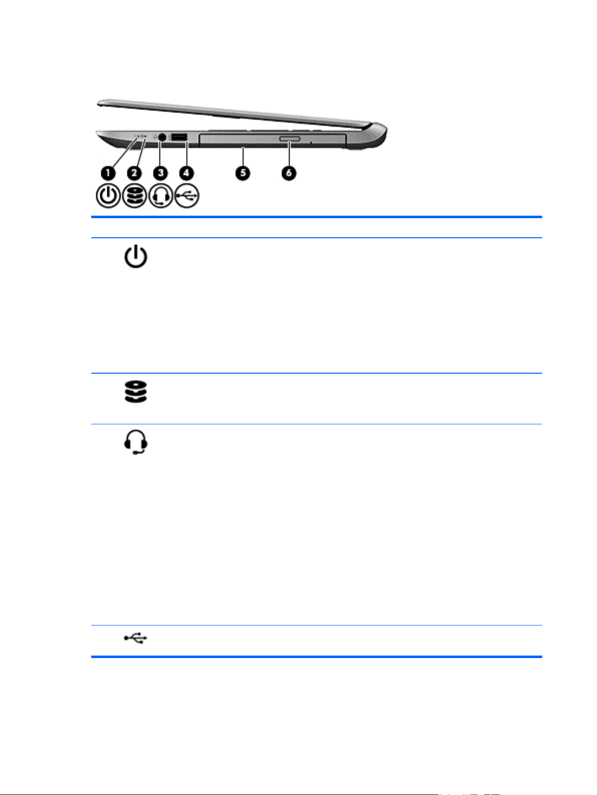
Right side
Component Description
(1)
(2)
(3)
Power light
Hard drive light
Audio-out (headphone) / Audio-in
(microphone) jack
On: The computer is on.
●
Blinking: The computer is in the Sleep state, a power-saving
●
state. The computer shuts off power to the display and other
unneeded components.
Off: The computer is off or in Hibernation. Hibernation is a
●
power-saving state that uses the least amount of power.
NOTE: For select models, the Intel Rapid Start Technology
feature is enabled at the factory. Rapid Start Technology
allows your computer to resume quickly from inactivity.
Blinking white: The hard drive is being accessed.
●
Amber: HP 3D DriveGuard has temporarily parked the hard
●
drive.
Connects optional powered stereo speakers, headphones,
earbuds, a headset, or a television audio cable. Also connects an
optional headset microphone. This jack does not support optional
microphone-only devices.
WARNING! To reduce the risk of personal injury, adjust the
volume before using the headphones, earbuds, or a headset. For
additional safety information, refer to the Regulatory, Safety and
Environmental Notices. To access this guide, from the Start screen,
type support, select the HP Support Assistant app, select
My computer, and then select User guides.
(4)
USB 2.0 port Connects an optional USB device, such as a keyboard, mouse,
8 Chapter 2 External component identification
NOTE: When a device is connected to the jack, the computer
speakers are disabled.
NOTE: Be sure that the device cable has a 4-conductor
connector that supports both audio-out (headphone) and audio-in
(microphone).
external drive, printer, scanner, or USB hub.
Page 19

Component Description
(5) Optical drive Reads and/or writes, depending on your computer model, to an
optical disc.
NOTE: For disc compatibility information, navigate to the Help
and Support webpage. Follow the web page instructions to select
your computer model. Select Support & Drivers, and then select
Product Information.
(6) Optical drive eject button Releases the disc tray.
Right side
9
Page 20
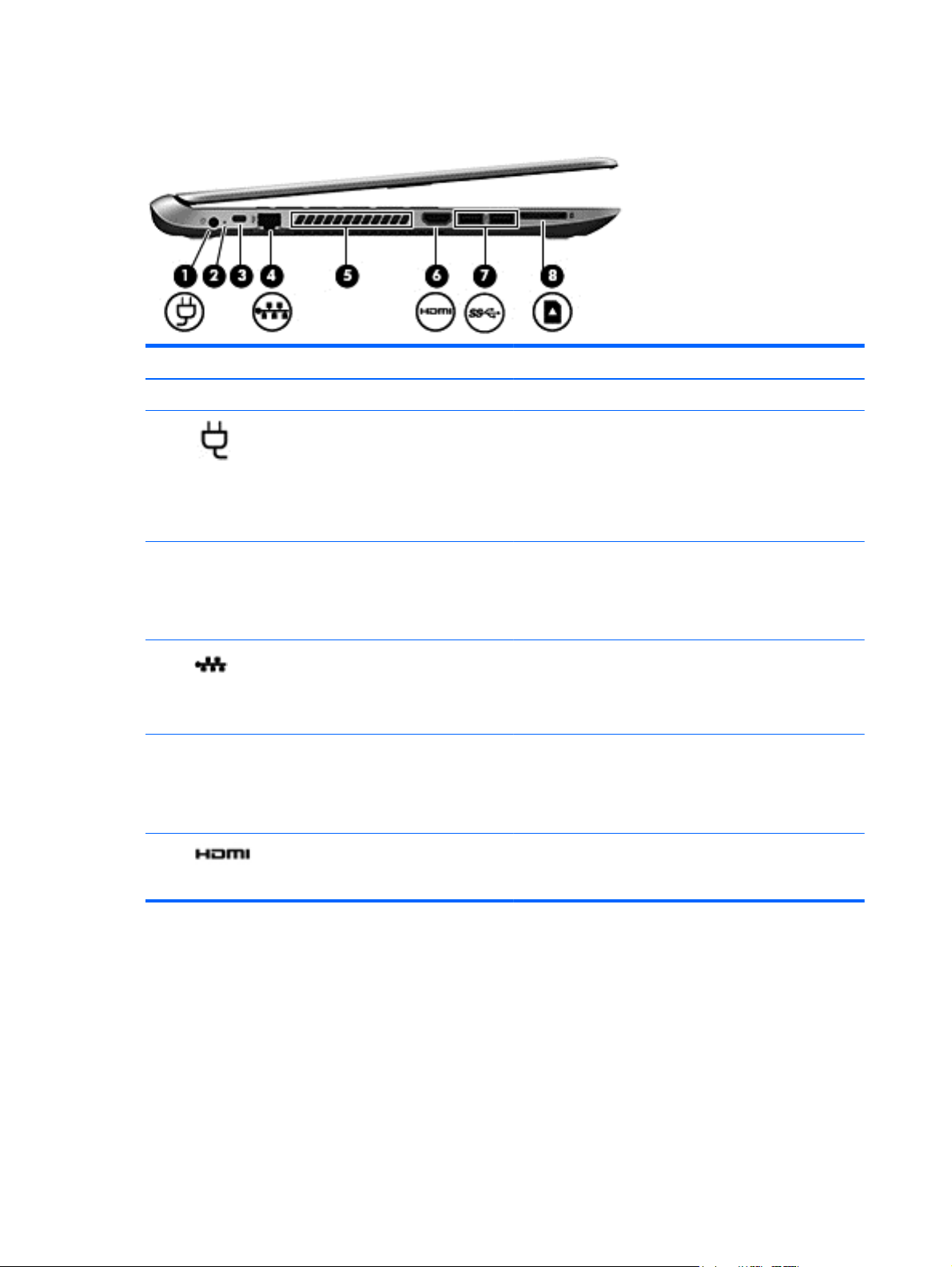
Left side
Component Description
(1) Power connector Connects an AC adapter.
(2)
(3) Security cable slot Attaches an optional security cable to the computer.
(4)
(5) Vent Enable airflow to cool internal components.
(6)
AC adapter light
RJ-45 (network) jack
RJ-45 (network) status lights (2)
HDMI port Connects an optional video or audio device, such as a high-
White: The AC adapter is connected and the battery is
●
charged.
Amber: The AC adapter is connected and the battery is
●
charging.
Off: The computer is using DC power.
●
NOTE: The security cable is designed to act as a
deterrent, but it may not prevent the computer from being
mishandled or stolen.
Connects a network cable.
White: The network is connected.
Amber: Activity is occurring on the network.
NOTE: The computer fan starts up automatically to cool
internal components and prevent overheating. It is normal for
the internal fan to cycle on and off during routine operation.
definition television, any compatible digital or audio
component, or a high-speed HDMI device.
10 Chapter 2 External component identification
Page 21

Component Description
(7)
(8)
USB 3.0 ports (2) Connect optional USB device, such as a keyboard, mouse,
external drive, printer, scanner or USB hub.
Memory card reader Reads data from and writes data to memory cards such as
Secure Digital (SD).
To insert:
1. Hold the card, label side up, with connectors facing the
slot and push in the card until it is firmly seated.
To remove:
1. Press in on the card and quickly release it until it pops
out.
Left side
11
Page 22
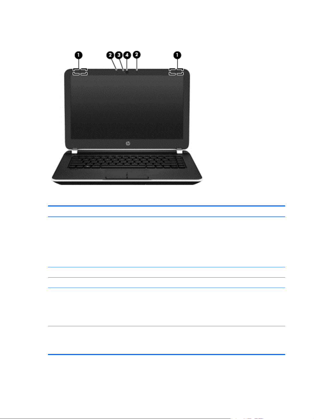
Display
Component Description
(1) WLAN antennas (2)* Send and receive wireless signals to communicate with wireless
local area networks (WLANs).
NOTE: To set up a WLAN and connect to the Internet, you
need a broadband modem (either DSL or cable) (purchased
separately), high-speed internet service purchased from an
Internet service provider, and a wireless router (purchased
separately).
(2) Internal microphones (2) Record sound.
(3) Webcam light On: The webcam is in use.
(4) Webcam Records video and captures photographs. Some models may
allow you to video conference and chat online using streaming
video.
To use the webcam, from the Start screen, type c, and then select
CyberLink YouCam from the list of applications.
*The antennas are not visible from the outside of the computer. For optimal transmission, keep the areas immediately around
the antennas free from obstructions. For wireless regulatory notices, see the section of the Regulatory, Safety, and
Environmental Notices that applies to your country or region. To access this guide, from the Start screen, type support, select
the HP Support Assistant app, select My computer, and then select User guides.
12 Chapter 2 External component identification
Page 23
Top
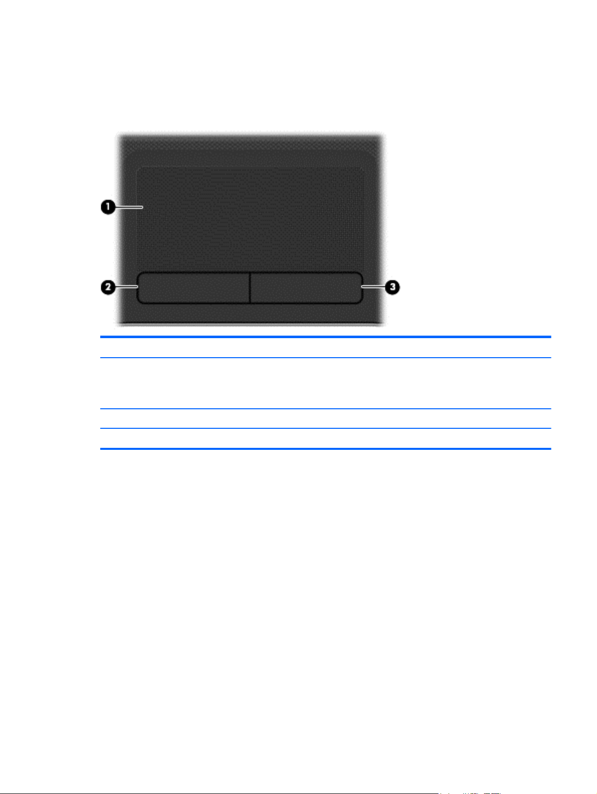
TouchPad
Component Description
(1) TouchPad zone Moves the on-screen pointer and selects or activates items on
the screen.
NOTE: The TouchPad also supports edge-swipe gestures.
(2) Left TouchPad button Functions like the left button on an external mouse.
(3) Right TouchPad button Functions like the right button on an external mouse.
Top
13
Page 24
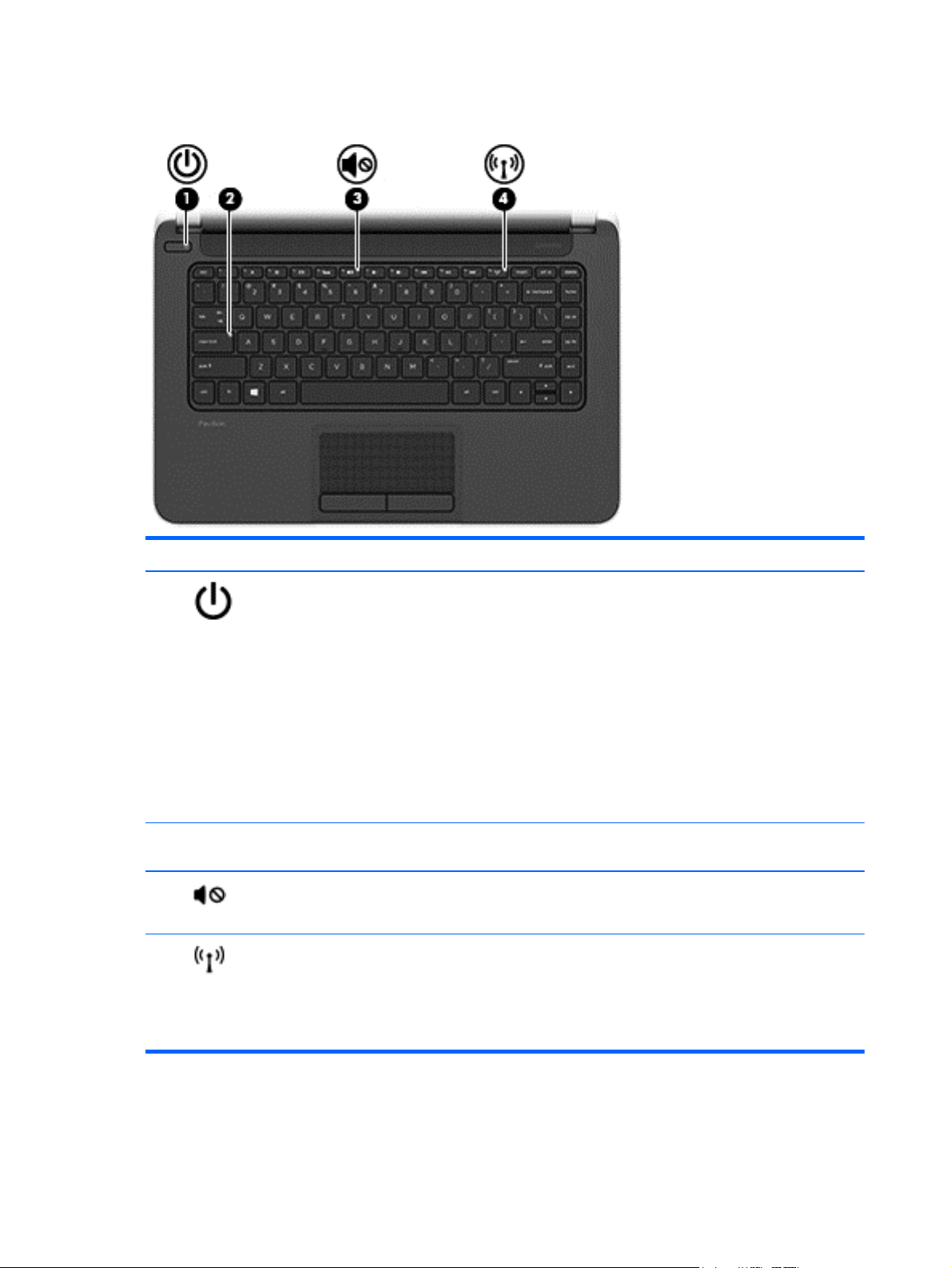
Lights
Component Description
(1)
(2) Caps lock light On: Caps lock is on, which switches the keys to all capital
(3)
(4)
Power light
Mute light
Wireless light On: An integrated wireless device, such as a wireless local
On: The computer is on.
●
Blinking: The computer is in the Sleep state, a power-
●
saving state. The computer shuts off power to the
display and other unneeded components.
Off: The computer is off or in Hibernation. Hibernation
●
is a power-saving state that uses the least amount of
power.
NOTE: For select models, the Intel Rapid Start
Technology feature is enabled at the factory. Rapid Start
Technology allows your computer to resume quickly
from inactivity.
letters.
Amber: Computer sound is off.
●
Off: Computer sound is on.
●
area network (WLAN) device and/or a Bluetooth® device, is
on.
NOTE: On some models, the wireless light is amber when
all wireless devices are off.
14 Chapter 2 External component identification
Page 25
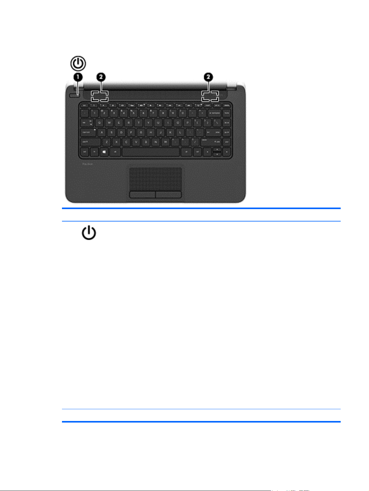
Buttons and speakers
Component Description
(1)
Power button
When the computer is off, press the button to turn on
●
the computer.
When the computer is on, press the button briefly to
●
initiate Sleep.
When the computer is in the Sleep state, press the
●
button briefly to exit Sleep.
When the computer is in Hibernation, press the button
●
briefly to exit Hibernation.
CAUTION: Pressing and holding down the power button
will result in the loss of unsaved information.
If the computer has stopped responding and Windows®
shutdown procedures are ineffective, press and hold the
power button down for at least 5 seconds to turn off the
computer.
NOTE: For select models, the Intel Rapid Start Technology
feature is enabled at the factory. Rapid Start Technology
allows your computer to resume quickly from inactivity.
To learn more about your power settings, see your power
options. From the Start screen, type power, select Settings,
and then select Power Options from the list of
applications.
(2) Speakers (2) Produce sound.
Top
15
Page 26
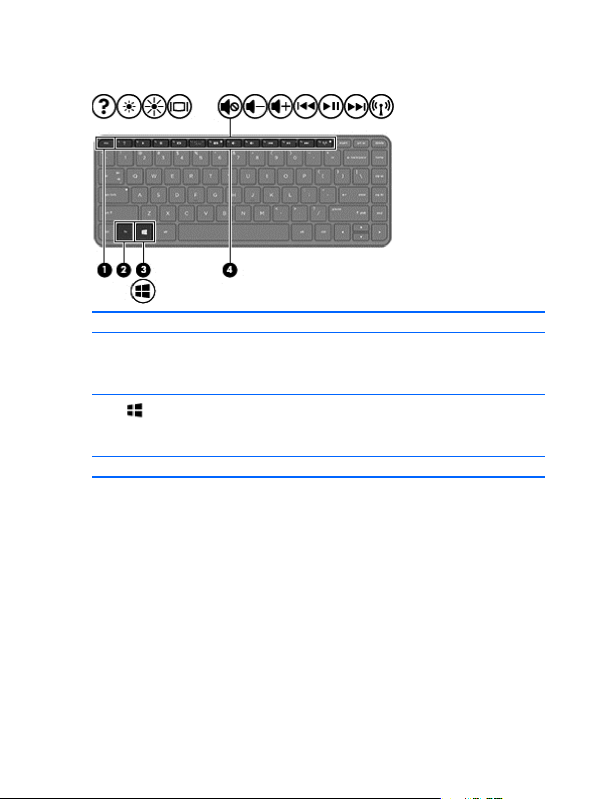
Keys
Component Description
(1) esc key Reveals system information when pressed in combination
with the fn key.
(2) fn key Executes frequently used system functions when pressed in
combination with the esc key.
(3)
(4) Action keys Execute frequently used system functions.
Windows key Returns you to the Start screen from an open app or the
Windows desktop.
NOTE: Pressing the Windows key again will return you to
the previous screen.
16 Chapter 2 External component identification
Page 27
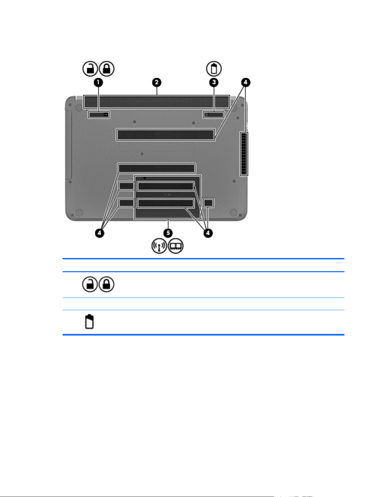
Bottom
Component Description
(1)
(2) Battery bay Holds the battery.
(3)
Battery lock latch Unlocks the battery.
Battery release latch Releases the battery from the battery bay, after the battery lock
latch has been released.
Bottom
17
Page 28

Component Description
(4) Vents (8) Enable airflow to cool internal components.
NOTE: The computer fan starts up automatically to cool internal
components and prevent overheating. It is normal for the internal
fan to cycle on and off during routine operation.
(5)
Service door Provides access to the wireless LAN (WLAN) module slot and the
memory module slots.
CAUTION: To prevent an unresponsive system, replace the
wireless module only with a wireless module authorized for use in
the computer by the governmental agency that regulates wireless
devices in your country or region. If you replace the module and
then receive a warning message, remove the module to restore
computer functionality, and then contact support through Help
and Support. From the Start screen, type h, and then select Help
and Support.
18 Chapter 2 External component identification
Page 29
Labels
The labels affixed to the computer provide information you may need when you troubleshoot system
problems or travel internationally with the computer.
IMPORTANT: All labels described in this section will be located in one of 3 places depending on
your computer model: Affixed to the bottom of the computer, located in the battery bay, or under the
service door.
For help finding these locations, refer to Bottom on page 17.
●
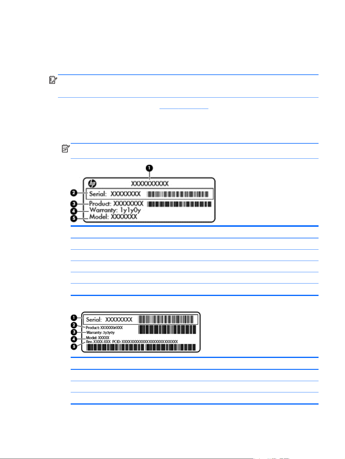
Service label—Provides important information to identify your computer. When contacting support,
you will probably be asked for the serial number, and possibly for the product number or the
model number. Locate these numbers before you contact support.
NOTE: Your service labels will resemble one of the examples shown below. Refer to the
illustration that most closely matches the service label on your computer.
Component
(1) Product name
(2) Serial number
(3) Product number
(4) Warranty period
(5) Model number (select models only)
Component
(1) Serial number
(2) Product number
(3) Warranty period
Labels
19
Page 30

Component
(4) Model number (select models only)
(5) Revision number
Regulatory label(s)—Provide(s) regulatory information about the computer.
●
Wireless certification label(s)—Provide(s) information about optional wireless devices and the
●
approval markings for the countries or regions in which the devices have been approved for use.
20 Chapter 2 External component identification
Page 31
3 Illustrated parts catalog
Computer major components
NOTE: HP continually improves and changes product parts. For complete and current information on
supported parts for your computer, go to
then follow the on-screen instructions.
NOTE: Details about your computer, including model, serial number, product key, and length of
warranty, are on the service tag at the bottom of your computer. See
http://partsurfer.hp.com, select your country or region, and
Labels on page 19 for details.
Computer major components
21
Page 32

22 Chapter 3 Illustrated parts catalog
Page 33

Item Component Spare part number
(1) Display assembly:
35.56 cm (14.0 in), high definition (HD), WLED, SVA BrightView flat display
assembly for use with HP Pavilion Notebooks. The display assembly is spared at the
subcomponent level only. For more display assembly spare part information, see
Display assembly subcomponents on page 30.
35.56 cm (14.0 in), high definition (HD), WLED, SVA BrightView TouchSmart slim
display assembly for use with HP Pavilion TouchSmart Notebooks:
Aluminum with midnight black 734414-001
Flyer red 734410-001
Goji berry 736814-001
Hazel berry 736815-001
Mineral black 736813-001
Pearl white 734409 -001
Raspberry 736816-001
Regal purple 734412-001
Revolutionary blue 734411-001
Silver 734413-001
(2) Keyboard (includes keyboard cable):
Textured island-style black finish for use in:
Brazil, for use with computer models with Intel processors 740102-201
Canada 740102-DB1
Czech Republic and Slovak Republic, for use with computer models with Intel
processors
France, for use with computer models with Intel processors 740102-051
Germany, for use with computer models with Intel processors 740102-041
International use, for use with computer models with Intel processors 740102-B31
Israel, for use with computer models with Intel processors 740102-BB1
Japan, for use with computer models with Intel processors 740102-291
Latin America 740102-161
Nordic regions, for use with computer models with Intel processors 740102-DH1
Portugal, for use with computer models with Intel processors 740102-131
Russia, for use with computer models with Intel processors 740102-251
Saudi Arabia, for use with computer models with Intel processors 740102-171
740102-FL1
South Korea 740102-AD1
Computer major components
23
Page 34

Item Component Spare part number
Spain 740102-071
Switzerland, for use with computer models with Intel processors 740102-BG1
Taiwan 740102-AB1
Thailand 740102-281
Turkey, for use with computer models with Intel processors 740102-141
United Kingdom, for use with computer models with Intel processors 740102-031
United States 740102-001
Painted island-style white finish for use in:
Brazil, for use with computer models with Intel processors 740103-201
Canada 740103-DB1
Czech Republic and Slovak Republic, for use with computer models with Intel
processors
France, for use with computer models with Intel processors 740103-051
Germany, for use with computer models with Intel processors 740103-041
International use, for use with computer models with Intel processors 740103-B31
Israel, for use with computer models with Intel processors 740103-BB1
Latin America 740103-161
Nordic regions, for use with computer models with Intel processors 740103-DH1
Portugal, for use with computer models with Intel processors 740103-131
Russia, for use with computer models with Intel processors 740103-251
Saudi Arabia, for use with computer models with Intel processors 740103-171
South Korea 740103-AD1
Spain, for use with computer models with Intel processors 740103-071
Switzerland, for use with computer models with Intel processors 740103-BG1
Taiwan 740103-AB1
Thailand 740103-281
740103-FL1
Turkey, for use with computer models with Intel processors 740103-141
United Kingdom, for use with computer models with Intel processors 740103-031
United States 740103-001
(3) Top cover (includes TouchPad and cable):
Aluminum with midnight black finish 734435-001
Flyer red finish 734431-001
Goji berry finish 736818-001
24 Chapter 3 Illustrated parts catalog
Page 35

Item Component Spare part number
Hazel berry finish 736819-001
Mineral black finish 736817-001
Pearl white finish 734430-001
Raspberry finish 736820-001
Regal purple finish 734433-001
Revolutionary blue finish 734432-001
Sparkling black finish 734434-001
(4) Power button board (includes cable) 734416-001
(5) TouchPad button board (includes cable) 734418-001
(6) Power connector bracket is available with the power connector cable, spare part number 732067-001
(7) USB/audio board (includes cable) 734417-001
(8) Hard drive (does not include hard drive rubber bracket, hard drive connector cable, or screws):
1 TB, 5400 rpm, 9.5 mm 676521-005
750 GB, 5400 rpm, 9.5 mm 634250-005
500 GB, 5400 rpm, 7.0 mm 683802-005
mSATA solid-state drive, 24 GB (for use with select computer models with Intel
processors, HM86 Express chipsets, and switchable discrete graphics)
Hard Drive Hardware Kit (not illustrated, includes hard drive rubber bracket,
hard drive connector cable, and screws)
(9) System board (includes replacement thermal material):
For computer models equipped with Intel processors and UMA graphics
4th generation
Intel Core i5-4200U 1.6 GHz processor (3.0 MB L3 cache, 15 W) for use with
FreeDOS and Ubuntu
Intel Core i5-4200U 1.6 GHz processor (3.0 MB L3 cache, 15 W) for use with
Windows Standard
Intel Core i5-4200U 1.6 GHz processor (3.0 MB L3 cache, 15 W) for use with
Windows Professional
Intel Core i3-4005U 1.7 GHz processor (3.0 MB L3 cache, 15 W) for use with
FreeDOS and Ubuntu
Intel Core i3-4005U 1.7 GHz processor (3.0 MB L3 cache, 15 W) for use with
Windows Standard
732085-001
740706-001
734423-001
734423-501
734423-601
734424-001
734424-501
Intel Core i3-4005U 1.7 GHz processor (3.0 MB L3 cache, 15 W) for use with
Windows Professional
For computer models equipped with Intel processors and UMA graphics
3rd generation
Computer major components
734424-601
25
Page 36

Item Component Spare part number
Intel HM76 chipset and Pentium 2117U HM76 (1.8 GHz, 2 MB L3 Cache, 1600
MHz DDR3, 17 W) for use with FreeDOS and Ubuntu
Intel HM76 chipset and Pentium 2117U HM76 (1.8 GHz, 2 MB L3 Cache, 1600
MHz DDR3, 17 W) for use with Windows Standard
Intel HM76 chipset and Pentium 2117U HM76 (1.8 GHz, 2 MB L3 Cache, 1600
MHz DDR3, 17 W) for use with Windows Professional
Intel HM76 chipset and Core i3-3217U (1.8 GHz, 3 MB L3 Cache, 1600 MHz
DDR3, 17 W) for use with FreeDOS and Ubuntu
Intel HM76 chipset and Core i3-3217U (1.8 GHz, 3 MB L3 Cache, 1600 MHz
DDR3, 17 W) for use with Windows Standard
Intel HM76 chipset and Core i3-3217U (1.8 GHz, 3 MB L3 Cache, 1600 MHz
DDR3, 17 W) for use with Windows Professional
For computer models equipped with Intel processors and discrete
graphics
4th generation
NVIDIA N14P-GV2 GeForce GT 740M 2 GB graphics and Intel Core i7-4500U (1.8
GHz DC 15 W) for use with FreeDOS and Ubuntu
NVIDIA N14P-GV2 GeForce GT 740M 2 GB graphics and Intel Core i7-4500U (1.8
GHz DC, 15 W) for use with Windows Standard
738148-001
738148-501
738148-601
738150-001
738150-501
738150-601
738154-001
738154-501
NVIDIA N14P-GV2 GeForce GT 740M 2 GB graphics and Intel Core i7-4500U (1.8
GHz DC, 15 W) for use with Windows Professional
AMD Radeon 8670M 2 GB graphics and Intel Core i7-4500U (1.8 GHz DC, 15 W)
for use with FreeDOS and Ubuntu
AMD Radeon 8670M 2 GB graphics and Intel Core i7-4500U (1.8 GHz DC, 15 W)
for use with Windows Standard
AMD Radeon 8670M 2 GB graphics and Intel Core i7-4500U (1.8 GHz DC, 15 W)
for use with Windows Professional
NVIDIA N14P-GV2 GeForce GT 740M 2 GB graphics and Intel Core i5-4200U (1.6
GHz DC, 15 W) for use with FreeDOS and Ubuntu
NVIDIA N14P-GV2 GeForce GT 740M 2 GB graphics and Intel Core i5-4200U (1.6
GHz DC, 15 W) for use with Windows Standard
NVIDIA N14P-GV2 GeForce GT 740M 2 GB graphics and Intel Core i5-4200U (1.6
GHz DC, 15 W) for use with Windows Professional
AMD Radeon 8670M 2 GB graphics and Intel Core i5-4200U (1.6 GHz DC, 15 W)
for use with FreeDOS and Ubuntu
AMD Radeon 8670M 2 GB graphics and Intel Core i5-4200U (1.6 GHz DC, 15 W)
for use with Windows Standard
AMD Radeon 8670M 2 GB graphics and Intel Core i5-4200U (1.6 GHz DC, 15 W)
for use with Windows Professional
738154-601
734429-001
734429-501
734429-601
738156-001
738156-501
738156-601
734426-001
734426-501
734426-601
AMD Radeon 8670M 1 GB graphics and Intel Core i3-4005U (1.7 GHz DC, 15 W)
for use with FreeDOS and Ubuntu
26 Chapter 3 Illustrated parts catalog
734427-001
Page 37

Item Component Spare part number
AMD Radeon 8670M 1 GB graphics and Intel Core i3-4005U (1.7 GHz DC, 15 W)
for use with Windows Standard
AMD Radeon 8670M 1 GB graphics and Intel Core i3-4005U (1.7 GHz DC, 15 W)
for use with Windows Professional
For computer models equipped with Intel processors and discrete
switchable graphics
3rd generation
AMD Radeon 8670M 2 GB graphics and Intel Core i3-3217U 8670M 2 GB HM76
(1.8 GHz, L3 Cache, 1600 MHz DDR3, 17 W) for use with FreeDOS and Ubuntu
AMD Radeon 8670M 2 GB graphics and Intel Core i3-3217U 8670M 2 GB HM76
(1.8 GHz, L3 Cache, 1600 MHz DDR3, 17 W) for use with Windows Standard
AMD Radeon 8670M 2 GB graphics and Intel Core i3-3217U 8670M 2 GB HM76
(1.8 GHz, L3 Cache, 1600 MHz DDR3, 17 W) for use with Windows Professional
For computer models equipped with AMD processors and UMA
graphics
AMD A4-5000 (1.5 GHz, 2 MB L2, 1600 MHz DDR3L, quad core,15 W) for use
with FreeDOS and Ubuntu
AMD A4-5000 (1.5 GHz, 2 MB L2, 1600 MHz DDR3L, quad core, 15 W) for use
with Windows Standard
734427-501
734427-601
738152-001
738152-501
738152-601
734443-001
734443-501
AMD A76M chipset, A6-4455M processor (2.6 GHz/2.1 GHz, 2 MB L2, 1333 MHz
DDR3L dual core, 19 W) for use with FreeDOS and Ubuntu
AMD A76M chipset, A6-4455M processor (2.6 GHz/2.1 GHz, 2 MB L2, 1333 MHz
DDR3L dual core, 19 W) for use with Windows Standard
AMD A6-5200 (2.6 GHz/2.1 GHz, 2 MB L2, 1600 MHz DDR3L, dual core, 17 W)
for use with FreeDOS and Ubuntu
AMD A6-5200 (2.6 GHz/2.1 GHz, 2 MB L2, 1600 MHz DDR3L, dual core, 17 W)
for use with Windows Standard
AMD A8-5545M A76M (2.7 GHz/1.7 GHz, 4 MB L2, 1333 MHz DDR3L quad
core, 19 W) for use with FreeDOS and Ubuntu
AMD A8-5545M A76M (2.7 GHz/1.7 GHz, 4 MB L2, 1333 MHz DDR3L quad
core, 19 W) for use with Windows Standard
AMD A76M chipset, A8-4555M processor (2.4 GHz/1.6 GHz, 4 MB L2, 1333 MHz
DDR3L quad core, 19 W) for use with FreeDOS and Ubuntu
AMD A76M chipset, A8-4555M processor (2.4 GHz/1.6 GHz, 4 MB L2, 1333 MHz
DDR3L quad core, 19 W) for use with Windows Standard
AMD E2-3000 (1.65 GHz, 1 MB L2, 1600 MHz DDR3L, dual core, 15 W) for use
with FreeDOS and Ubuntu
AMD E2-3000 (1.65 GHz, 1 MB L2, 1600 MHz DDR3L, dual core, 15 W) for use
with Windows Standard
736821-001
736821-501
734444-001
734444-501
734446-001
734446-501
736822-001
736822-501
734447-001
734447-501
For computer models equipped with AMD processors and discrete
switchable graphics
Computer major components
27
Page 38

Item Component Spare part number
AMD Radeon 8670M 1 GB graphics A6-5200 processor (2.6 GHz/2.1 GHz, 2 MB
L2, 1600 MHz DDR3L, dual core, 17 W) for use with FreeDOS and Ubuntu
AMD Radeon 8670M 1 GB graphics A6-5200 processor (2.6 GHz/2.1 GHz, 2 MB
L2, 1600 MHz DDR3L, dual core, 17 W) for use with Windows Standard
AMD Radeon 8670M 2 GB graphics and A10-5745M processor (2.9 GHz/2.1
GHz, 4 MB L2, 1333 MHz DDR3L quad core, 25 W) for use with FreeDOS and
Ubuntu
AMD Radeon 8670M 2 GB graphics and A10-5745M processor (2.9 GHz/2.1
GHz, 4 MB L2, 1333 MHz DDR3L quad core, 25 W) for use with Windows Standard
(10) Fan 732068-001
(11) RTC battery 697917-001
(12) Heat sink assembly (includes replacement thermal material):
For use only on computer models equipped with Intel processors and switchable
discrete graphics
For use only on computer models equipped with Intel processors and UMA graphics 742581-001
For use only on computer models equipped with Intel HM76 chipset and switchable
discrete graphics
For use only on computer models equipped with Intel HM76 chipset and
UMA graphics
734440-001
734440-501
734441-001
734441-501
742582-001
742331-001
742330-001
For use only on computer models equipped with AMD processors and UMA graphics
19 W
For use only on computer models equipped with AMD processors and UMA graphics
25 W
For use only on computer models equipped with AMD processors and switchable
discrete graphics 19 W
For use only on computer models equipped with AMD processors and switchable
discrete graphics 25 W
(13) Power connector cable (includes bracket): 732067-001
(14) Hard drive connector cable is available in the Hard Drive Hardware Kit, part number 740706-001
(15) Memory modules (2), (PC3L, 12800, 1600 MHz):
2 GB memory module 691739-001
4 GB memory module 691740-001
8 GB memory module 693374-001
(16) WLAN module:
Intel Wireless-N 7260BN 802.11 bgn 2x2 Wi-Fi + BT 4.0 combo adaptor for use
with computer models with Intel processors, not supported on Ubuntu
Mediatek MT7630E 802.11 bgn Wi-Fi Adapter and Mediatek Bluetooth 4.0 Adapter
for use with computer models with Intel processors
734448-001
734449-001
734450-001
734451-001
717384-001
710418-001
28 Chapter 3 Illustrated parts catalog
Page 39

Item Component Spare part number
Qualcomm Atheros AR9485 802.11 bgn Wi-Fi Adapter 675794-001
Ralink RT3290LE 802.11 bgn 1×1 Wi-Fi and Bluetooth 4.0 Combo Adapter 690020-001
Realtek RTL8188EE 802.11 bgn Wi-Fi Adapter 709848-001
(17) Speakers (include subwoofer, speaker cables, and rubber isolators) 734422-001
(18) Battery
4 cell, 41 Whr, 2.8 Ah, Li-ion battery 728460-001
4 cell, 48 Whr, 3.2 Ah, Li-ion battery, for use with computer models with Intel
processors
(19) Base enclosure (includes battery release latch mechanism, RJ45 cover, and screws) 734406-001
(20) Optical drive, SuperMulti DVD±R/RW Double-Layer Drive (includes bezel, bracket,
and screws)
(21) Service door (part of the Plastics Kit 734419-001)
728461-001
734415-001
Computer major components
29
Page 40

Display assembly subcomponents
NOTE: The display assembly subcomponents are for the HP Pavilion flat display models only. HP
Pavilion TouchSmart Notebooks are spared at the display assembly only.
Item Component Spare part number
(1) Display bezel (includes 2 rubber screws) 739355-001
(2) 35.56 cm (14 in), BrightView, HD, WLED, SVA flat display panel (Screws
included in the screw kit, spare part number 734421-001)
(3) Webcamera/microphone module (includes adhesive and screws) 725665-001
(4) Display panel cable (includes webcamera/microphone module cable and screws) 734407-001
(5) Antenna Kit (includes left and right wireless antenna cables and transceivers and 2
rubber screws)
(6) Display Hinge Kit (includes left and right hinges and 2 rubber screws) 734408-001
(7) Display back cover (includes 2 rubber screws):
Aluminum with midnight black finish 734405-001
Flyer red finish 734401-001
Goji berry finish 736810-001
Hazel berry finish 736811-001
Mineral black finish 736809-001
Pearl white finish 726193-001
734420-001
734400-001
Raspberry finish 736812-001
30 Chapter 3 Illustrated parts catalog
Page 41

Item Component Spare part number
Regal purple finish 734403-001
Revolutionary blue finish 734402-001
Silver finish 734404-001
Miscellaneous parts
Component Spare part number
AC adapter:
45 W HP Smart AC adapter (nPFC, RC, 3-wire, 4.5 mm)
65 W HP Smart AC adapter (nPFC, RC, 3-wire, 4.5 mm), select models only 714657-001
65 W HP Smart AC adapter (nPFC, RC, 3-wire, 4.5 mm) 710412-001
90 W HP Smart AC adapter (PFC, RC, 3-wire, 4.5 mm), for use with computer models with AMD
processors
90 W HP Smart AC adapter (PFC, RC, 3-wire, 4.5 mm), for use with computer models with AMD
processors, select models only
Power cord (3 pin, black, 1.83 m):
For use in the United States 490371-001
For use in Argentina 490371-D01
For use in Australia, for use with computer models with Intel processors 490371-011
For use in Brazil 490371-202
For use in Denmark, for use with computer models with Intel processors 490371-081
For use in Europe 490371-021
For use in India 490371-D61
For use in Israel, for use with computer models with Intel processors 490371-BB1
For use in Italy 490371-061
For use in Japan, for use with computer models with Intel processors 490371-291
For use in the People's Republic of China 490371-AA1
710413-001
710414-001
For use in South Africa, for use with computer models with Intel processors 490371-AR1
For use in South Korea 490371-AD1
For use in Switzerland, for use with computer models with Intel processors 490371-111
For use in Taiwan 490371-AB1
For use in Thailand 490371-201
Miscellaneous parts
31
Page 42

Component Spare part number
For use in the United Kingdom and Singapore 490371-031
Screw Kit 734421-001
HDMI to VGA Adapter for use with computer models with AMD processors 701943-001
32 Chapter 3 Illustrated parts catalog
Page 43
Mass storage devices
Item Component Spare part number
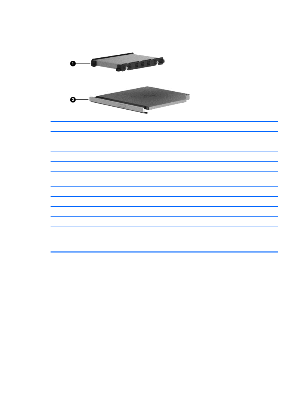
(1) Hard drive (does not include the hard drive rubber bracket, hard drive connector cable, or screws)
1 TB, 5400 rpm, 9.5 mm 676521-005
750 GB, 5400 rpm, 9.5 mm 634250-005
500 GB 5400 rpm 7 mm 683802-005
mSATA solid-state drive, 24 GB (for use with select computer models with Intel
processors, HM86 Express chipsets, and switchable discrete graphics)
Hard Drive Hardware Kit, includes: 740706-001
Hard drive rubber bracket
Hard drive connector cable
Hard drive screws
(3) Optical drive:
DVD+/-RW DL SuperMulti -- support Zero power ODD (includes optical drive hardware
kit with optical drive bezel, bracket and connector cable).
732085-001
734415-001
Mass storage devices
33
Page 44

Sequential part number listing
Spare part number Description
490371-001 Power cord for use in North America (3 pin, black, 1.83 m)
490371-011 Power cord for use in Australia (3 pin, black, 1.83 m), for use with computer models with Intel
processors
490371-021 Power cord for use in Europe (3 pin, black, 1.83 m)
490371-031 Power cord for use in the United Kingdom and Singapore (3 pin, black, 1.83 m)
490371-061 Power cord for use in Italy (3 pin, black, 1.83 m
490371-081 Power cord for use in Denmark (3 pin, black, 1.83 m), for use with computer models with Intel
processors
49037-111 Power cord for use in Switzerland (3 pin, black, 1.83 m), for use with computer models with Intel
processors
490371-201 Power cord for use in Thailand (3 pin, black, 1.83 m)
490371-202 Power cord for use in Brazil (3 pin, black, 1.83 m), for use with computer models with Intel
processors
490371-291 Power cord for use in Japan (3 pin, black, 1.83 m), for use with computer models with Intel
processors
490371-AA1 Power cord for use in the People's Republic of China (3 pin, black, 1.83 m)
490371-AB1 Power cord for use in Taiwan (3 pin, black, 1.83 m)
490371-AD1 Power cord for use in South Korea (3 pin, black, 1.83 m)
490371-AR1 Power cord for use in South Africa (3 pin, black, 1.83 m), for use with computer models with Intel
processors
490371-BB1 Power cord for use in Israel (3 pin, black, 1.83 m), for use with computer models with Intel
processors
490371-D01 Power cord for use in Argentina (3 pin, black, 1.83 m)
490371-D61 Power cord for use in India (3 pin, black, 1.83 m)
634250-005 750 GB, 5400 rpm hard drive (SATA, 9.5 mm, does not include hard drive rubber bracket, hard
drive connector cable, or screws)
NOTE: The hard drive rubber bracket, hard drive connector cable, and screws are included in the
Hard Drive Hardware Kit, spare part number 740706-001.
675794-001 Qualcomm Atheros AR9485 802.11 bgn Wi-Fi Adapter
676521-005 1 TB, 5400 rpm hard drive (SATA, 9.5 mm, does not include hard drive rubber bracket, hard drive
connector cable, or screws)
NOTE: The hard drive rubber bracket, hard drive connector cable, and screws are included in the
Hard Drive Hardware Kit, spare part number 740706-001.
34 Chapter 3 Illustrated parts catalog
Page 45

Spare part number Description
683802-005 500 GB, 5400 rpm hard drive (SATA, 7.0 mm, does not include hard drive rubber bracket, hard
drive connector cable, or screws)
NOTE: The hard drive rubber bracket, hard drive connector cable, and screws are included in the
Hard Drive Hardware Kit, spare part number 740706-001.
690020-001 Ralink RT3290LE 802.11 bgn 1×1 Wi-Fi and Bluetooth 4.0 Combo Adapter
691739-001 2 GB memory module (PC3, 12800, 1600 MHz)
691740-001 4 GB memory module (PC3, 12800, 1600 MHz)
693374-001 8 GB memory module (PC3, 12800, 1600 MHz)
697917-001 RTC battery
701943-001 HDMI to VGA adapter for use with computer models with AMD processors
709848-001 Realtek RTL8188EE 802.11 bgn Wi-Fi Adapter
710412-001 65 W HP Smart AC adapter (nPFC, RC, 3-wire, 4.5 mm), select models only
710413-001 90 W HP Smart AC adapter (PFC, RC, 3-wire, 4.5 mm) for use with computer models with AMD
processors
710414-001 90 W HP Smart AC adapter (PFC, RC, 3-wire, 4.5 mm) for use with computer models with AMD
processors, select models only
710418-001 Mediatek MT7630E 802.11 bgn Wi-Fi Adapter and Mediatek Bluetooth 4.0 Adapter, for use with
computer models with Intel processors
714657-001 65 W HP Smart AC adapter (nPFC, RC, 3-wire, 4.5 mm), select models only
717384-001 Intel Wireless-N 7260BN 802.11 bgn 2x2 Wi-Fi + BT 4.0 combo adaptor for use with computer
models with Intel processors; not supported on Ubuntu
725665-001 Webcamera/microphone module (includes adhesive and screws)
726193-001 Display back cover in pearl white (includes screws)
728460-001 4 cell, 41 Whr, 2.8 Ah, Li-ion battery
728461-001 4 cell, 48 Whr, 3.2 Ah, Li-ion battery, for use with computer models with Intel processors
732067-001 Power connector cable (includes bracket)
732068-001 Fan
732085-001 mSATA solid-state drive, 24 GB, for use with select computer models with Intel processors, HM86
Express chipsets, and switchable discrete graphics, (does not include hard drive rubber bracket,
hard drive connector cable, or screws)
NOTE: The hard drive rubber bracket, hard drive connector cable, and screws are included in the
Hard Drive Hardware Kit, spare part number 740706-001.
734400-001 Antenna Kit (includes left and right wireless antenna cables and transceivers and 2 rubber screws)
734401-001 Display back cover in flyer red
734402-001 Display back cover in revolutionary blue
734403-001 Display back cover in regal purple
Sequential part number listing
35
Page 46

Spare part number Description
734404-001 Display back cover in silver finish (includes 2 rubber screw covers)
734405-001 Display back cover in aluminum with midnight black
734406-001 Base enclosure (includes battery release latch mechanism , RJ-45 cover, and screws)
734407-001 Display panel cable (includes (includes webcamera/microphone module cable and screws )
734408-001 Display Hinge Kit (includes left and right hinges and 2 rubber screws)
734409-001 Display assembly, pearl white, 35.56 cm (14.0 in), high definition (HD), WLED, SVA BrightView
TouchSmart slim display assembly for use with HP Pavilion TouchSmart Notebooks
734410-001 Display assembly, flyer red, 35.56 cm (14.0 in), high definition (HD), WLED, SVA BrightView
TouchSmart slim display assembly for use with HP Pavilion TouchSmart Notebooks
734411-001 Display assembly, revolutionary blue, 35.56 cm (14.0 in), high definition (HD), WLED, SVA
BrightView TouchSmart slim display assembly for use with HP Pavilion TouchSmart Notebooks
734412-001 Display assembly, regal purple, 35.56 cm (14.0 in), high definition (HD), WLED, SVA BrightView
TouchSmart slim display assembly for use with HP Pavilion TouchSmart Notebooks
734413-001 Display assembly, silver, 35.56 cm (14.0 in), high definition (HD), WLED, SVA BrightView
TouchSmart slim display assembly for use with HP Pavilion TouchSmart Notebooks
734414-001 Display assembly, aluminum with midnight black, 35.56 cm (14.0 in), high definition (HD),
WLED, SVA BrightView TouchSmart slim display assembly for use with HP Pavilion TouchSmart
Notebooks
734415-001 Optical drive, DVD±RW Double-Layer SuperMulti Drive (includes bezel and bracket)
734416-001 Power button board (includes cable)
734417-001 USB/audio board (includes cable)
734418-001 TouchPad button board (includes cable)
734419-001 Plastics Kit (includes service door)
734420-001 35.56 cm (14 in), WLED, HD, BrightView flat display panel for use with HP Pavilion Notebooks
only
734421-001 Screw Kit
734422-001 Speakers (include subwoofer, speaker cables, and rubber isolators)
734423-001 System board for use with computer models with UMA graphics, Intel HM86 Express chipset, and
Core i5-4200U 1.6 GHz processor (3.0 MB L3 cache, 15 W) for use with FreeDOS and Ubuntu
(includes replacement thermal material)
734423-501 System board for use with computer models with UMA graphics, Intel HM86 Express chipset, and
Core i5-4200U 1.6 GHz processor (3.0 MB L3 cache, 15 W) for use with Windows Standard
(includes replacement thermal material)
734423-601 System board for use with computer models with UMA graphics, Intel HM86 Express chipset, and
Core i5-4200U 1.6 GHz processor (3.0 MB L3 cache, 15 W) for use with Windows Professional.
(includes replacement thermal material)
734424-001 System board for use with computer models with UMA graphics, Intel HM86 Express chipset, and
Core i3-4005U 1.7 GHz processor (3.0 MB L3 cache, 15 W) for use with FreeDOS and Ubuntu
(includes replacement thermal material)
36 Chapter 3 Illustrated parts catalog
Page 47

Spare part number Description
734424-501 System board for use with computer models with UMA graphics, Intel HM86 Express chipset, and
Core i3-4005U 1.7 GHz processor (3.0 MB L3 cache, 15 W) for use with Windows Standard
(includes replacement thermal material)
734424-601 System board for use with computer models with UMA graphics, Intel HM86 Express chipset, and
Core i3-4005U 1.7 GHz processor (3.0 MB L3 cache, 15 W) for use with Windows Professional
(includes replacement thermal material)
734426-001 System board for use with computer models with switchable discrete graphics, AMD Radeon
8670M 2 GB graphics and Intel Core i5-4200U (1.6 GHz processor 3.0 MB L3 cache, 15 W) for
use with FreeDOS and Ubuntu (includes replacement thermal material)
734426-501 System board for use with computer models with switchable discrete graphics, AMD Radeon
8670M 2 GB graphics and Intel Core i5-4200U (1.6 GHz processor 3.0 MB L3 cache, 15 W) for
use with Windows Standard (includes replacement thermal material)
734426-601 System board for use with computer models with switchable discrete graphics, AMD Radeon
8670M 2 GB graphics and Intel Core i5-4200U (1.6 GHz processor 3.0 MB L3 cache, 15 W) for
use with Windows Professional (includes replacement thermal material)
734427-001 System board for use with computer models with switchable discrete graphics, AMD Radeon
8670M 1 GB graphics and Intel Core i3-4005U (1.7 GHz DC, 15 W) for use with FreeDOS and
Ubuntu (includes replacement thermal material)
734427-501 System board for use with computer models with switchable discrete graphics, AMD Radeon
8670M 1 GB graphics and Intel Core i3-4005U (1.7 GHz DC, 15 W) for use with Windows
Standard (includes replacement thermal material)
734427-601 System board for use with computer models with switchable discrete graphics, AMD Radeon
8670M 1 GB graphics and Intel Core i3-4005U (1.7 GHz DC, 15 W) for use with Windows
Professional (includes replacement thermal material)
734429-001 System board for use with computer models with switchable discrete graphics, AMD Radeon
8670M 2 GB graphics and Intel Core i7-4500U (1.8 GHz DC, 15 W) for use with FreeDOS and
Ubuntu
734429-501 System board for use with computer models with switchable discrete graphics, AMD Radeon
8670M 2 GB graphics and Intel Core i7-4500U (1.8 GHz DC, 15 W) for use with Windows
Standard
734429-601 System board for use with computer models with switchable discrete graphics, AMD Radeon
8670M 2 GB graphics and Intel Core i7-4500U (1.8 GHz DC, 15 W) for use with Windows
Professional
734430-001 Top cover in pearl white finish (includes TouchPad and cable)
734431-001 Top cover in flyer red finish (includes TouchPad and cable)
734432-001 Top cover in revolutionary blue finish (includes TouchPad and cable)
734433-001 Top cover in regal purple finish (includes TouchPad and cable)
734434-001 Top cover in sparkling black finish (includes TouchPad and cable)
734435-001 Top cover in aluminum with midnight black finish (includes TouchPad and cable)
734440-001 System board for use with computer models with switchable discrete graphics, AMD Radeon
8670M 1 GB graphics and A6-5200 processor (2.6 GHz/2.1 GHz, 2 MB L2, 1600 MHz DDR3L,
dual core, 17 W) for use with FreeDOS and Ubuntu
Sequential part number listing
37
Page 48

Spare part number Description
734440-501 System board for use with computer models with switchable discrete graphics, AMD Radeon
8670M 1 GB graphics and A6-5200 processor (2.6 GHz/2.1 GHz, 2 MB L2, 1600 MHz DDR3L,
dual core, 17 W) for use with Windows Standard
734441-001 System board for use with computer models with switchable discrete graphics, AMD Radeon
8670M 2 GB graphics and A10-5745M processor (2.9GHz/2.1GHz, 2 GB L2, 1333 MHz
DDR3L quad core, 25 W) for use with FreeDOS and Ubuntu
734441-501 System board for use with computer models with switchable discrete graphics, AMD Radeon
8670M 2 GB graphics and A10-5745M processor (2.9 GHz/2.1 GHz, 2 GB L2, 1333 MHz
DDR3L quad core, 25 W) for use with Windows Standard
734443-001 System board for use with computer models with UMA graphics, AMD A4-5000 (1.5 GHz, 2 MB
L2, 1600 MHz DDR3L, quad core, 15 W) for use with FreeDOS and Ubuntu
734443-501 System board for use with computer models with UMA graphics, AMD A4-5000 (1.5 GHz, 2 MB
L2, 1600 MHz DDR3L, quad core, 15 W) for use with Windows Standard
734444-001 System board for use with computer models with UMA graphics, AMD A6-5200 (2.6 GHz/
2.1GHz, 2 MB L2, 1600 MHz DDR3L, dual core, 17 W) for use with FreeDOS and Ubuntu
734444-501 System board for use with computer models with UMA graphics, AMD A6-5200 (2.6 GHz/2.1
GHz, 2 MB L2, 1600 MHz DDR3L, dual core, 17 W) for use with Windows Standard
734446-001 System board for use with computer models with UMA graphics, AMD A8-5545M A76M (2.7
GHz/1.7 GHz, 4 MB L2, 1333 MHz DDR3L quad core, 19 W) for use with FreeDOS and Ubuntu
734446-501 System board for use with computer models with UMA graphics, AMD A8-5545M A76M (2.7
GHz/1.7 GHz, 4 MB L2, 1333 MHz DDR3L quad core, 19 W) for use with Windows Standard
734447-001 System board for use with computer models with UMA graphics, AMD E2-3000 (1.65 GHz, 1 MB
L2, 1600 MHz DDR3L, dual core, 15 W) for use with FreeDOS and Ubuntu
734447-501 System board for use with computer models with UMA graphics, AMD E2-3000 (1.65 GHz, 1 MB
L2, 1600 MHz DDR3L, dual core, 15 W) for use with Windows Standard
734448-001 Heat sink for use only on computer models equipped with a graphics subsystem with AMD UMA
graphics, 19 W
734449-001 Heat sink for use only on computer models equipped with a graphics subsystem with AMD UMA
graphics, 25 W
734451-001 Heat sink for use only on computer models equipped with a graphics subsystem with AMD
switchable discrete graphics, 25 W
736809-001 Display back cover in mineral black finish
736810-001 Display back cover in goji berry finish
736811-001 Display back cover in hazel berry finish
736812-001 Display back cover in raspberry finish
736813-001 Display assembly, mineral black, 35.56 cm (14.0 in), high definition (HD), WLED, SVA
BrightView TouchSmart slim display assembly for use with HP Pavilion TouchSmart Notebooks
736814-001 Display assembly, goji berry, 35.56 cm (14.0 in), high definition (HD), WLED, SVA BrightView
TouchSmart slim display assembly for use with HP Pavilion TouchSmart Notebooks
736815-001 Display assembly, hazel berry, 35.56 cm (14.0 in), high definition (HD), WLED, SVA BrightView
TouchSmart slim display assembly for use with HP Pavilion TouchSmart Notebooks
38 Chapter 3 Illustrated parts catalog
Page 49

Spare part number Description
736816-001 Display assembly, raspberry, 35.56 cm (14.0 in), high definition (HD), WLED, SVA BrightView
TouchSmart slim display assembly for use with HP Pavilion TouchSmart Notebooks
736817-001 Top cover in mineral black finish (includes TouchPad and cable)
736818-001 Top cover in goji berry finish (includes TouchPad and cable)
736819-001 Top cover in hazel berry finish (includes TouchPad and cable)
736820-001 Top cover in raspberry finish (includes TouchPad and cable)
736821-001 System board for use with computer models with UMA graphics, AMD A76M chipset, A6-4455M
processor (2.6 GHz/2.1 GHz, 2 MB L2, 1333 MHz DDR3L Dual 19 W) for use with FreeDOS and
Ubuntu
736821-501 System board for use with computer models with UMA graphics, AMD A76M chipset, A6-4455M
processor (2.6 GHz/2.1 GHz, 2 MB L2, 1333 MHz DDR3L Dual 19 W) for use with Windows
Standard
736822-001 System board for use with computer models with UMA graphics, AMD A76M chipset, A8 4555M
processor (2.4 GHz/1.6 GHz, 4 MB L2, 1333 MHz DDR3L quad core, 19 W) for use with
FreeDOS and Ubuntu
736822-501 System board for use with computer models with UMA graphics, AMD A76M chipset, A8-4555M
processor (2.4 GHz/1.6 GHz, 4 MB L2, 1333 MHz DDR3L quad core, 19 W) for use with
Windows Standard
738148-001 System board for use with computer models with UMA graphics, Intel HM76 chipset and Pentium
2117U HM76 (1.8 GHz, 2 MB L3 Cache, 1600 MHz DDR3, 17 W) for use with FreeDOS and
Ubuntu
738148-501 System board for use with computer models with UMA graphics, Intel HM76 chipset and Pentium
2117U HM76 (1.8 GHz, 2 MB L3 Cache, 1600 MHz DDR3, 17 W) for use with Windows
Standard
738148-601 System board for use with computer models with UMA graphics, Intel HM76 chipset and Pentium
2117U HM76 (1.8 GHz, 2 MB L3 Cache, 1600 MHz DDR3, 17 W) for use with Windows
Professional
738150-001 System board for use with computer models with UMA graphics, Intel HM76 chipset and Core
i3-3217U (1.8 GHz, 3 MB L3 Cache, 1600 MHz DDR3, 17 W) for use with FreeDOS and Ubuntu.
738150-501 System board for use with computer models with UMA graphics, Intel HM76 chipset and Core
i3-3217U (1.8 GHz, 3 MB L3 Cache, 1600 MHz DDR3, 17 W) for use with Windows Standard
738150-601 System board for use with computer models with UMA graphics, Intel HM76 chipset and Core
i3-3217U (1.8 GHz, 3 MB L3 Cache, 1600 MHz DDR3, 17 W) for use with Windows Professional
738152-001 System board for use with computer models with switchable discrete graphics, AMD Radeon
8670M 2 GB graphics and Intel Core i3-3217U (1.8 GHz, 3 MB, L3 Cache, 1600 MHz DDR3,
17 W) for use with FreeDOS and Ubuntu
738152-501 System board for use with computer models with switchable discrete graphics, AMD Radeon
8670M 2GB graphics and Intel Core i3-3217U 8670M 2 GB (1.8 GHz, 3 MB, L3 Cache, 1600
MHz DDR3, 17 W) for use with Windows Standard
738152-601 System board for use with computer models with switchable discrete graphics, AMD Radeon
8670M 2GB graphics and Intel Core i3-3217U 8670M 2 GB (1.8 GHz, 3 MB, L3 Cache, 1600
MHz DDR3, 17 W) for use with Windows Professional
Sequential part number listing
39
Page 50

Spare part number Description
738154-001 System board for use with computer models with switchable discrete graphics, NVIDIA N14P-GV2
GeForce GT 740M 2 GB graphics and Intel Core i7-4500U (1.8 GHz DC, 15 W) for use with
FreeDOS and Ubuntu
738154-501 System board for use with computer models with switchable discrete graphics, NVIDIA N14P-GV2
GeForce GT 740M 2 GB graphics and Intel Core i7-4500U (1.8 GHz DC, 15 W) for use with
Windows Standard
738154-601 System board for use with computer models with switchable discrete graphics, NVIDIA N14P-GV2
GeForce GT 740M 2 GB graphics and Intel Core i7-4500U (1.8 GHz DC, 15 W) for use with
Windows Professional
738156-001 System board for use with computer models with switchable discrete graphics, NVIDIA N14P-GV2
GeForce GT 740M 2 GB graphics and Intel Core i5-4200U (1.6 GHz DC, 15 W) for use with
FreeDOS and Ubuntu
738156-501 System board for use with computer models with switchable discrete graphics, NVIDIA N14P-GV2
GeForce GT 740M 2 GB graphics and Intel Core i5-4200U (1.6 GHz DC, 15 W) for use with
Windows Standard
738156-601 System board for use with computer models with switchable discrete graphics, NVIDIA N14P-GV2
GeForce GT 740M 2 GB graphics and Intel Core i5-4200U (1.6 GHz DC, 15 W) for use with
Windows Professional
739355-001 Display bezel (includes 2 rubber screw covers and rubber bumpers), for the HP Pavilion flat display
models only
740102-001 Keyboard in black finish for use in the United States (includes keyboard cable)
740102-031 Keyboard in black finish for use in the United Kingdom (includes keyboard cable) for use with
computer models with Intel processors
740102-041 Keyboard in black finish for use in Germany (includes keyboard cable) for use with computer
models with Intel processors
740102-051 Keyboard in black finish for use in France (includes keyboard cable) for use with computer models
with Intel processors
740102-071 Keyboard in black finish for use in Spain (includes keyboard cable) for use with computer models
with Intel processors
740102-131 Keyboard in black finish for use in Portugal (includes keyboard cable) for use with computer models
with Intel processors
740102-141 Keyboard in black finish for use in Turkey (includes keyboard cable) for use with computer models
with Intel processors
740102-161 Keyboard in black finish for use in Latin America (includes keyboard cable)
740102-171 Keyboard in black finish for use in Saudi Arabia (includes keyboard cable) for use with computer
models with Intel processors
740102-201 Keyboard in black finish for use in Brazil (includes keyboard cable) for use with computer models
with Intel processors
740102-251 Keyboard in black finish for use in Russia (includes keyboard cable) for use with computer models
with Intel processors
740102-281 Keyboard in black finish for use in Thailand (includes keyboard cable)
40 Chapter 3 Illustrated parts catalog
Page 51

Spare part number Description
740102-291 Keyboard in black finish for use in Japan (includes keyboard cable) for use with computer models
with Intel processors
740102-AB1 Keyboard in black finish for use in Taiwan (includes keyboard cable)
740102-AD1 Keyboard in black finish for us in South Korea (includes keyboard cable)
740102-B31 Keyboard in black finish for International use (includes keyboard cable) for use with computer
models with Intel processors
740102-BB1 Keyboard in black finish for use in Israel (includes keyboard cable) for use with computer models
with Intel processors
740102-BG1 Keyboard in black finish for use in Switzerland (includes keyboard cable) for use with computer
models with Intel processors
740102-DB1 Keyboard in black finish for use in Canada (includes keyboard cable)
740102-DH1 Keyboard in black finish for use in Nordic regions (includes keyboard cable) for use with computer
models with Intel processors
740102-FL1 Keyboard in black finish for use in the Czech Republic and Slovak Republic (includes
keyboard cable) for use with computer models with Intel processors
740103-001 Keyboard in painted island-style pearl white finish for use in the United States (includes
keyboard cable)
740103-031 Keyboard in painted island-style pearl white finish for use in United Kingdom (includes
keyboard cable), for use with computer models with Intel processors
740103-041 Keyboard in painted island-style pearl white finish for use in Germany (includes keyboard cable),
for use with computer models with Intel processors
740103-051 Keyboard in painted island-style pearl white finish for use in France (includes keyboard cable), for
use with computer models with Intel processors
740103-071 Keyboard in painted island-style pearl white finish for use in Spain (includes keyboard cable), for
use with computer models with Intel processors
740103-131 Keyboard in painted island-style pearl white finish for use in Portugal (includes keyboard cable), for
use with computer models with Intel processors
740103-141 Keyboard in painted island-style pearl white finish for use in Turkey (includes keyboard cable), for
use with computer models with Intel processors
740103-161 Keyboard in painted island-style pearl white finish for use in Latin America (includes
keyboard cable)
740103-171 Keyboard in painted island-style pearl white finish for use in Saudi Arabia (includes
keyboard cable), for use with computer models with Intel processors
740103-201 Keyboard in painted island-style pearl white finish for use in Brazil (includes keyboard cable), for
use with computer models with Intel processors
740103-251 Keyboard in painted island-style pearl white finish for use in Russia (includes keyboard cable), for
use with computer models with Intel processors
740103-281 Keyboard in painted island-style pearl white finish for use in Thailand (includes keyboard cable)
740103-291 Keyboard in painted island-style pearl white finish for use in Japan (includes keyboard cable), for
use with computer models with Intel processors
Sequential part number listing
41
Page 52

Spare part number Description
740103-AB1 Keyboard in painted island-style pearl white finish for use in Taiwan (includes keyboard cable)
740103-AD1 Keyboard in painted island-style pearl white finish for use in South Korea (includes keyboard cable)
740103-B31 Keyboard in painted island-style pearl white finish for International use (includes keyboard cable),
for use with computer models with Intel processors
740103-BB1 Keyboard in painted island-style pearl white finish for use in Israel (includes keyboard cable), for
use with computer models with Intel processors
740103-BG1 Keyboard in painted island-style pearl white finish for use in Switzerland (includes keyboard cable),
for use with computer models with Intel processors
740103-DB1 Keyboard in painted island-style pearl white finish for use in Canada (includes keyboard cable)
740103-DH1 Keyboard in painted island-style pearl white finish for use in Nordic regions (includes
keyboard cable) for use with computer models with Intel processors
740103-FL1 Keyboard in painted island-style pearl white finish for use in the Czech Republic and Slovak
Republic (includes keyboard cable) for use with computer models with Intel processors
740706-001 Hard Drive Hardware Kit (includes hard drive rubber bracket, hard drive connector cable, and
screws)
742330-001 For use only on computer models equipped with Intel HM76 chipset and UMA graphics
742331-001 For use only on computer models equipped with Intel HM76 chipset and switchable discrete
graphics
742581-001 For use only on computer models equipped with Intel processors and UMA graphics
742582-001 For use only on computer models equipped with Intel processors and switchable discrete graphics
42 Chapter 3 Illustrated parts catalog
Page 53

4 Removal and replacement
procedures preliminary
requirements
Tools required
You will need the following tools to complete the removal and replacement procedures:
Flat-bladed screwdriver
●
Magnetic screwdriver
●
Phillips P0 and P1 screwdrivers
●
Service considerations
The following sections include some of the considerations that you must keep in mind during
disassembly and assembly procedures.
NOTE: As you remove each subassembly from the computer, place the subassembly (and all
accompanying screws) away from the work area to prevent damage.
Plastic parts
CAUTION: Using excessive force during disassembly and reassembly can damage plastic parts. Use
care when handling the plastic
Tools required
43
Page 54

Cables and connectors
CAUTION: When servicing the computer, be sure that cables are placed in their proper locations
during the reassembly process. Improper cable placement can damage the computer.
Cables must be handled with extreme care to avoid damage. Apply only the tension required to unseat
or seat the cables during removal and insertion. Handle cables by the connector whenever possible. In
all cases, avoid bending, twisting, or tearing cables. Be sure that cables are routed in such a way that
they cannot be caught or snagged by parts being removed or replaced. Handle flex cables with
extreme care; these cables tear easily.
Drive handling
CAUTION: Drives are fragile components that must be handled with care. To prevent damage to the
computer, damage to a drive, or loss of information, observe these precautions:
Before removing or inserting a hard drive, shut down the computer. If you are unsure whether the
computer is off or in Hibernation, turn the computer on, and then shut it down through the operating
system.
Before handling a drive, be sure that you are discharged of static electricity. While handling a drive,
avoid touching the connector.
Before removing a diskette drive or optical drive, be sure that a diskette or disc is not in the drive and
be sure that the optical drive tray is closed.
Handle drives on surfaces covered with at least one inch of shock-proof foam.
Avoid dropping drives from any height onto any surface.
Avoid exposing an internal hard drive to products that have magnetic fields, such as monitors or
speakers.
Avoid exposing an internal hard drive to products that have magnetic fields, such as monitors or
speakers.
Avoid exposing a drive to temperature extremes or liquids.
If a drive must be mailed, place the drive in a bubble pack mailer or other suitable form of protective
packaging and label the package “FRAGILE.”
44 Chapter 4 Removal and replacement procedures preliminary requirements
Page 55

Grounding guidelines
Electrostatic discharge damage
Electronic components are sensitive to electrostatic discharge (ESD). Circuitry design and structure
determine the degree of sensitivity. Networks built into many integrated circuits provide some
protection, but in many cases, ESD contains enough power to alter device parameters or melt silicon
junctions.
A discharge of static electricity from a finger or other conductor can destroy static-sensitive devices or
microcircuitry. Even if the spark is neither felt nor heard, damage may have occurred.
An electronic device exposed to ESD may not be affected at all and can work perfectly throughout a
normal cycle. Or the device may function normally for a while, then degrade in the internal layers,
reducing its life expectancy.
CAUTION: To prevent damage to the computer when you are removing or installing internal
components, observe these precautions:
Keep components in their electrostatic-safe containers until you are ready to install them.
Before touching an electronic component, discharge static electricity by using the guidelines described
in this section.
Avoid touching pins, leads, and circuitry. Handle electronic components as little as possible.
If you remove a component, place it in an electrostatic-safe container.
The following table shows how humidity affects the electrostatic voltage levels generated by different
activities.
CAUTION: A product can be degraded by as little as 700 V.
Typical electrostatic voltage levels
Relative humidity
Event 10% 40% 55%
Walking across carpet 35,000 V 15,000 V 7,500 V
Walking across vinyl floor 12,000 V 5,000 V 3,000 V
Motions of bench worker 6,000 V 800 V 400 V
Removing DIPS from plastic tube 2,000 V 700 V 400 V
Removing DIPS from vinyl tray 11,500 V 4,000 V 2,000 V
Removing DIPS from Styrofoam 14,500 V 5,000 V 3,500 V
Removing bubble pack from PCB 26,500 V 20,000 V 7,000 V
Packing PCBs in foam-lined box 21,000 V 11,000 V 5,000 V
Grounding guidelines
45
Page 56

Packaging and transporting guidelines
Follow these grounding guidelines when packaging and transporting equipment:
To avoid hand contact, transport products in static-safe tubes, bags, or boxes.
●
Protect ESD-sensitive parts and assemblies with conductive or approved containers or packaging.
●
Keep ESD-sensitive parts in their containers until the parts arrive at static-free workstations.
●
Place items on a grounded surface before removing items from their containers.
●
Always be properly grounded when touching a component or assembly.
●
Store reusable ESD-sensitive parts from assemblies in protective packaging or nonconductive
●
foam.
Use transporters and conveyors made of antistatic belts and roller bushings. Be sure that
●
mechanized equipment used for moving materials is wired to ground and that proper materials
are selected to avoid static charging. When grounding is not possible, use an ionizer to dissipate
electric charges.
Workstation guidelines
Follow these grounding workstation guidelines:
Cover the workstation with approved static-shielding material.
●
Use a wrist strap connected to a properly grounded work surface and use properly grounded tools
●
and equipment.
Use conductive field service tools, such as cutters, screwdrivers, and vacuums.
●
When fixtures must directly contact dissipative surfaces, use fixtures made only of staticsafe
●
materials.
Keep the work area free of nonconductive materials, such as ordinary plastic assembly aids and
●
Styrofoam.
Handle ESD-sensitive components, parts, and assemblies by the case or PCM laminate. Handle
●
these items only at static-free workstations.
Avoid contact with pins, leads, or circuitry.
●
Turn off power and input signals before inserting or removing connectors or test equipment.
●
46 Chapter 4 Removal and replacement procedures preliminary requirements
Page 57

Equipment guidelines
Grounding equipment must include either a wrist strap or a foot strap at a grounded workstation.
When seated, wear a wrist strap connected to a grounded system. Wrist straps are flexible straps
●
with a minimum of one megohm ±10% resistance in the ground cords. To provide proper ground,
wear a strap snugly against the skin at all times. On grounded mats with banana-plug connectors,
use alligator clips to connect a wrist strap.
When standing, use foot straps and a grounded floor mat. Foot straps (heel, toe, or boot straps)
●
can be used at standing workstations and are compatible with most types of shoes or boots. On
conductive floors or dissipative floor mats, use foot straps on both feet with a minimum of one
megohm resistance between the operator and ground. To be effective, the conductive must be
worn in contact with the skin.
The following grounding equipment is recommended to prevent electrostatic damage:
Antistatic tape
●
Antistatic smocks, aprons, and sleeve protectors
●
Conductive bins and other assembly or soldering aids
●
Nonconductive foam
●
Conductive tabletop workstations with ground cords of one megohm resistance
●
Static-dissipative tables or floor mats with hard ties to the ground
●
Field service kits
●
Static awareness labels
●
Material-handling packages
●
Nonconductive plastic bags, tubes, or boxes
●
Metal tote boxes
●
Electrostatic voltage levels and protective materials
●
The following table lists the shielding protection provided by antistatic bags and floor mats.
Material Use Voltage protection level
Antistatic plastics Bags 1,500 V
Carbon-loaded plastic Floor mats 7,500 V
Metallized laminate Floor mats 5,000 V
Grounding guidelines
47
Page 58
5 Removal and replacement
procedures for Customer SelfRepair parts
NOTE: HP continually improves and changes product parts. For complete and current information on
supported parts for your computer, go to
then follow the on-screen instructions.
NOTE: The Customer Self-Repair program is not available in all locations. Installing a part not
supported by the Customer Self-Repair program may void your warranty. Check your warranty to
determine if Customer Self-Repair is supported in your location.
http://partsurfer.hp.com, select your country or region, and
Component replacement procedures
NOTE: Please read and follow the procedures described here to access and replace Customer Self-
Repair parts successfully.
NOTE: Details about your computer, including model, serial number, product key, and length of
warranty, are on the service tag at the bottom of your computer. See
This chapter provides removal and replacement procedures for Customer Self-Repair parts.
There may be as many as 5 screws that must be removed, replaced, and/or loosened when servicing
Customer Self-Repair parts. Make special note of each screw size and location during removal
and replacement.
Labels on page 19 for details.
48 Chapter 5 Removal and replacement procedures for Customer Self-Repair parts
Page 59

Battery
Description Spare part number
4 cell, 41 Whr, 2.8 Ah, Li-ion battery 728460-001
4 cell, 48 Whr, 3.2 Ah, Li-ion battery, for use with computer models with Intel processors 728461-001
Before disassembling the computer, follow these steps:
1. Turn off the computer. If you are unsure whether the computer is off or in Hibernation, turn
the computer on, and then shut it down through the operating system.
2. Disconnect the power from the computer by unplugging the power cord from the computer.
3. Disconnect all external devices from the computer.
Remove the battery:
1. Turn the computer upside down on a flat surface.
2. Firmly slide the battery lock latch (1) to unlock the battery and slide the battery release latch (2) to
release the battery.
3. Slide the battery (3) from the middle to remove it from the computer.
To insert the battery:
CAUTION: Do not slant the battery as you insert it. Slide the battery in straight.
1. Holding the battery in the middle, slide the battery (1) straight into the computer until the battery
release latch locks into place.
Component replacement procedures
49
Page 60

2. Reset the battery lock latch (2) to the locked position.
Service door
Description Spare part number
Service door is available with the Plastics Kit. 734419-001
1. Using a small Phillips screwdriver, loosen the service door screw (1).
2. Lift the door (2).
3. Slide the service door (3) forward to remove.
50 Chapter 5 Removal and replacement procedures for Customer Self-Repair parts
Page 61

Memory module
Description Spare part number
4 GB memory module (PC3, 12800, 1600 MHz) 691740-001
2 GB memory module (PC3, 12800, 1600 MHz) 691739-001
8 GB memory module (PC3, 12800, 1600 MHz) 693374-001
NOTE: Before adding memory modules, make sure the computer has the most recent BIOS version,
and update the BIOS if needed. For Windows operating systems, see
on page 105; for Linux Ubuntu, see Updating the BIOS on page 110.
Before removing a memory module, follow these steps:
1. Turn off the computer. If you are unsure whether the computer is off or in Hibernation, turn
the computer on, and then shut it down through the operating system.
2. Disconnect the power from the computer by unplugging the power cord from the computer.
3. Disconnect all external devices from the computer.
Updating the BIOS
4. Remove the battery (see
5. Remove the service door (see
Battery on page 49).
Service door on page 50).
Remove the memory module:
NOTE: Note the location of the memory module (1) you are removing. If you are replacing it, install
the new memory module in the same slot.
1. Spread the two retaining tabs (1) on each side of the memory module slot to release
the memory module. (The memory module tilts up.)
Component replacement procedures
51
Page 62
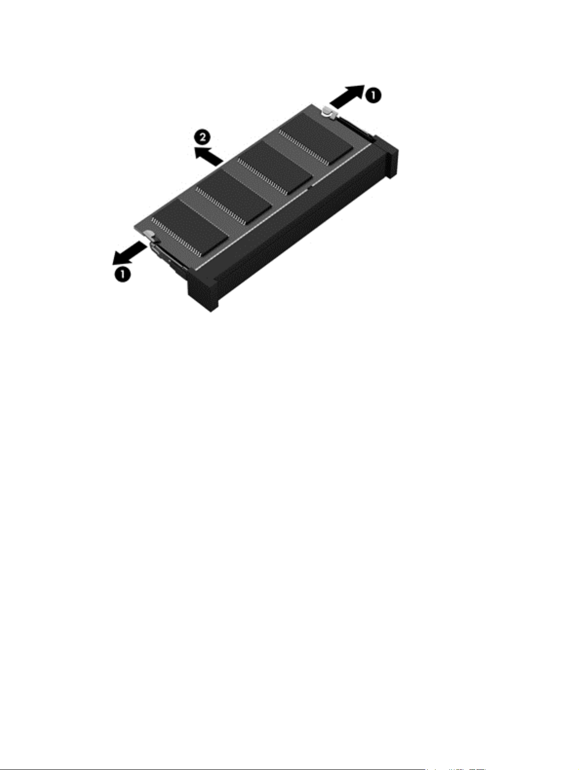
2. Remove the memory module (2) by pulling it away from the slot at a 45 degree angle.
Reverse this procedure to install the memory module.
52 Chapter 5 Removal and replacement procedures for Customer Self-Repair parts
Page 63
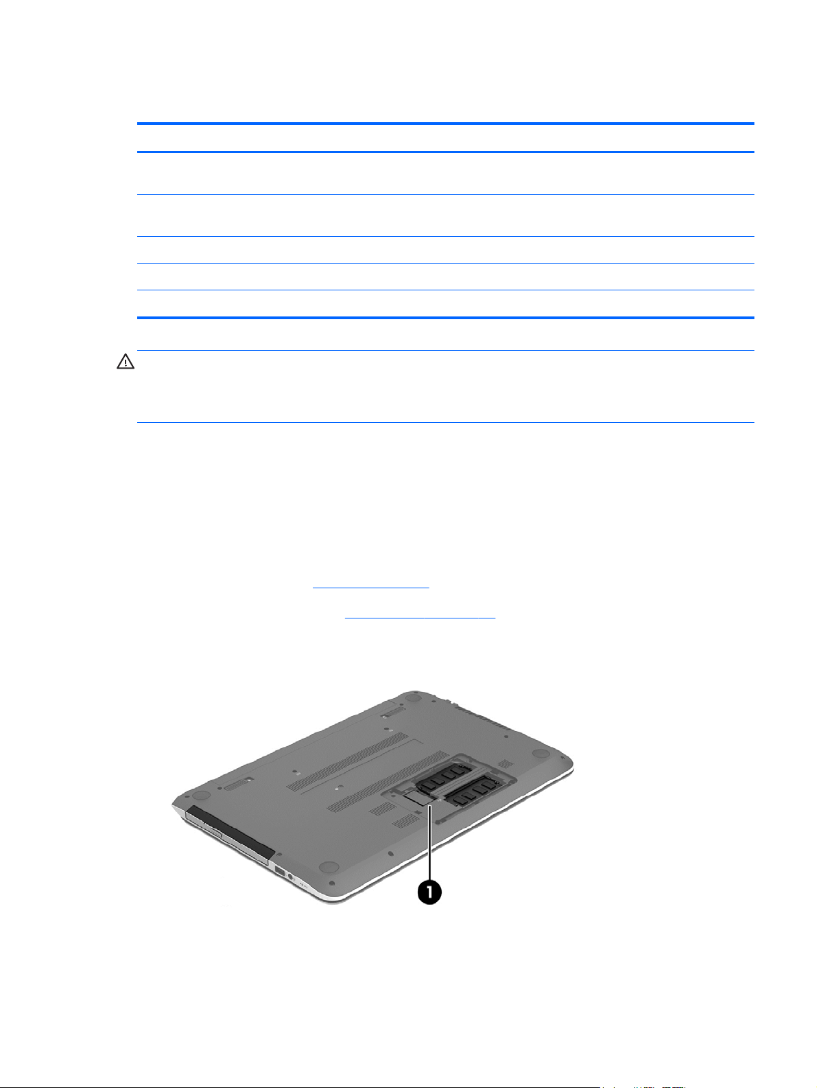
WLAN module
Description Spare part number
Intel Wireless-N 7260BN 802.11 bgn 2x2 Wi-Fi + BT 4.0 combo adaptor for use with computer
models with Intel processors; not supported on Ubuntu
Mediatek MT7630E 802.11 bgn Wi-Fi Adapter and Mediatek Bluetooth 4.0 Adapter for use with
computer models with Intel processors
Qualcomm Atheros AR9485 802.11 bgn Wi-Fi Adapter 675794-001
Ralink RT3290LE 802.11 bgn 1×1 Wi-Fi and Bluetooth 4.0 Combo Adapter 690020-001
Realtek RTL8188EE 802.11 bgn Wi-Fi Adapter 709848-001
717384-001
710418-001
CAUTION: To prevent an unresponsive system, replace the wireless module only with a wireless
module authorized for use in the computer by the governmental agency that regulates wireless devices
in your country or region. If you replace the module and then receive a warning message, remove
the module to restore device functionality, and then contact technical support.
Before removing the WLAN module, follow these steps:
1. Turn off the computer. If you are unsure whether the computer is off or in Hibernation, turn
the computer on, and then shut it down through the operating system.
2. Disconnect the power from the computer by unplugging the power cord from the computer.
3. Disconnect all external devices from the computer.
4. Remove the battery (see
Battery on page 49).
5. Remove the service door (see
6. Locate the WLAN module (1).
Service door on page 50).
Component replacement procedures
53
Page 64

Remove the WLAN module:
1. Disconnect the WLAN antenna cables (1) from the terminals on the WLAN module.
NOTE: The #1 WLAN antenna cable is connected to the WLAN module “Main” terminal.
The #2 WLAN antenna cable is connected to the WLAN module “Aux” terminal.
2. Remove the Phillips M2.0×2.5 screw (2) that secures the WLAN module to the system board.
(The WLAN module tilts up.)
3. Remove the WLAN module (3) by pulling the module away from the slot at an angle.
NOTE: If the WLAN antennas are not connected to the terminals on the WLAN module, the protective
sleeves should be installed on the antenna connectors, as shown in the following illustration.
54 Chapter 5 Removal and replacement procedures for Customer Self-Repair parts
Page 65

Reverse this procedure to install the WLAN module.
Optical drive
NOTE: The optical drive spare part kit includes a bezel and bracket.
Description Spare part number
Optical drive, SuperMulti DVD±R/RW Double-Layer Drive (includes bezel, bracket, and screws) 734415-001
Before removing the optical drive, follow these steps:
1. Turn off the computer. If you are unsure whether the computer is off or in Hibernation, turn
the computer on, and then shut it down through the operating system.
2. Disconnect the power from the computer by unplugging the power cord from the computer.
3. Disconnect all external devices from the computer.
4. Remove the battery (see
Battery on page 49).
Remove the optical drive:
1. Using a small Phillips screwdriver, remove the Phillips M2.5×6.5 screw that secures the optical
drive to the computer (1).
2. Using the screwdriver, push on the rear of the optical drive to disconnect it from the computer
Component replacement procedures
55
Page 66

3. If necessary, use an unbent paperclip and press in gently on the paper clip (2) until the disc tray
releases. Pull the tray (3) out from the front until the optical drive is completely removed from
the computer.
If it is necessary to replace the optical drive bracket and bezel, position the optical drive with the rear
panel toward you.
1. Remove the two Phillips screws from the optical drive (1) and remove the bracket (2).
56 Chapter 5 Removal and replacement procedures for Customer Self-Repair parts
Page 67

2. Use an unbent paperclip and press in gently on the paper clip (1) and release from the tab (2)
until the disc tray releases. Tilt the tray (3) and pull the bezel (4) to remove it.
Reverse this procedure to reassemble and install the optical drive.
Component replacement procedures
57
Page 68

6 Removal and replacement
procedures for Authorized Service
Provider parts
NOTE: HP continually improves and changes product parts. For complete and current information on
supported parts for your computer, go to
then follow the on-screen instructions.
CAUTION: Components described in this chapter should only be accessed by an authorized service
provider. Accessing these parts can damage the computer or void the warranty.
http://partsurfer.hp.com, select your country or region, and
Component replacement procedures
NOTE: Details about your computer, including model, serial number, product key, and length of
warranty, are on the service tag at the bottom of your computer. See
This chapter provides removal and replacement procedures for Authorized Service Provider only parts.
There may be as many as 51 screws that must be removed, replaced, and/or loosened when servicing
Authorized Service Provider only parts. Make special note of each screw size and location during
removal and replacement.
Labels on page 19 for details.
58 Chapter 6 Removal and replacement procedures for Authorized Service Provider parts
Page 69

Display panel
NOTE: These procedures are for replacing the display panel for HP Pavilion Notebook. For
procedures to replace the HP Pavilion Notebook display assembly subcomponents, see
assembly on page 98 and then Display assembly subcomponents on page 101. For procedures to
replace the HP Pavilion TouchSmart display assembly, see
Description Spare part number
Display bezel (includes 2 rubber screws) 739355-001
Display panel, 35.56 cm (14 in), WLED, HD, BrightView flat display panel 734420-001
IMPORTANT: Make special note of each screw and screw lock size and location during removal
and replacement
Before removing the display panel, follow these steps:
1. Turn off the computer. If you are unsure whether the computer is off or in Hibernation, turn
the computer on, and then shut it down through the operating system.
2. Disconnect the power from the computer by unplugging the power cord from the computer.
3. Disconnect all external devices from the computer.
Display
Display assembly on page 98.
4. Remove the battery (see
Battery on page 49).
Remove the panel:
If it is necessary to replace the display bezel:
1. Remove the plastic screw covers (1) and the two Phillips M2.5×3.0 screws (2) that secure
the display bezel to the display assembly.
2. If it is necessary to replace the display bezel or any of the display assembly subcomponents:
a. Flex the inside edges of the bottom edge (3), the left and right sides (4), and the top edge
(5) of the display bezel until the bezel disengages from the display enclosure.
Component replacement procedures
59
Page 70

b. Remove the display bezel (6).
60 Chapter 6 Removal and replacement procedures for Authorized Service Provider parts
Page 71

c. Remove the four Phillips M2.0×2.5 screws (1) and carefully move the display panel (2) to
the keyboard.
Release the tab (1) and disconnect the display panel cable connector (2). Lift the panel (3)
to remove it.
Reverse this procedure to replace the panel.
Component replacement procedures
61
Page 72

Keyboard
NOTE: The keyboard spare part kit includes a keyboard cable.
Description Spare part number
Textured island-style black finish for use in the United States 740102-001
Textured island-style black finish for use in United Kingdom 740102-031
Textured island-style black finish for use in Germany 740102-041
Textured island-style black finish for use in France 740102-051
Textured island-style black finish for use in Spain 740102-071
Textured island-style black finish for use in Portugal 740102-131
Textured island-style black finish for use in Turkey 740102-141
Textured island-style black finish for use in Latin America 740102-161
Textured island-style black finish for use in Saudi Arabia 740102-171
Textured island-style black finish for use in Brazil 740102-201
Textured island-style black finish for use in Russia 740102-251
Textured island-style black finish for use in Thailand 740102-281
Textured island-style black finish for use in Japan 740102-291
Textured island-style black finish for use in Taiwan 740102-AB1
Textured island-style black finish for use in South Korea 740102-AD1
Textured island-style black finish for International use 740102-B31
Textured island-style black finish for use in Israel 740102-BB1
Textured island-style black finish for use in Switzerland 740102-BG1
Textured island-style black finish for use in Canada 740102-DB1
Textured island-style black finish for use in Nordic regions 740102-DH1
Textured island-style black finish for use in the Czech Republic and Slovak Republic, for use with
computer models with Intel processors
Painted island-style white finish for use in the United States 740103-001
Painted island-style white finish for use in the United Kingdom, for use with computer models with
Intel processors
Painted island-style white finish for use in Greece, for use with computer models with Intel
processors
Painted island-style white finish for use in France, for use with computer models with Intel
processors
740102-FL1
740103-031
740103-041
740103-051
Painted island-style white finish for use in Spain, for use with computer models with Intel processors 740103-071
62 Chapter 6 Removal and replacement procedures for Authorized Service Provider parts
Page 73

Description Spare part number
Painted island-style white finish for use in Portugal, for use with computer models with Intel
processors
Painted island-style white finish for use in Turkey, for use with computer models with Intel
processors
Painted island-style white finish for use in Latin America 740103-161
Painted island-style white finish for use in Saudi Arabia, for use with computer models with Intel
processors
Painted island-style white finish for use in Brazil, for use with computer models with Intel processors 740103-201
Painted island-style white finish for use in Russia, for use with computer models with Intel
processors
Painted island-style white finish for use in Thailand 740103-281
Painted island-style white finish for use in Japan, for use with computer models with Intel
processors
Painted island-style white finish for use in Taiwan 740103-AB1
Painted island-style white finish for use in Korea 740103-AD1
Painted island-style white finish for International use, for use with computer models with Intel
processors
Painted island-style white finish for use in Israel, for use with computer models with Intel processors 740103-BB1
740103-131
740103-141
740103-171
740103-251
740597-291
740103-B31
Painted island-style white finish for use in Switzerland, for use with computer models with Intel
processors
Painted island-style white finish for use in Canada 740103-DB1
Painted island-style white finish for use in Nordic regions, for use with computer models with Intel
processors
Painted island-style white finish for use in the Czech Republic and Slovak Republic, for use with
computer models with Intel processors
740103-BG1
740103-DH1
740103-FL1
Before removing the keyboard, follow these steps:
1. Turn off the computer. If you are unsure whether the computer is off or in Hibernation, turn
the computer on, and then shut it down through the operating system.
2. Disconnect the power from the computer by unplugging the power cord from the computer.
3. Disconnect all external devices from the computer.
4. Remove the battery (see
Battery on page 49).
Component replacement procedures
63
Page 74
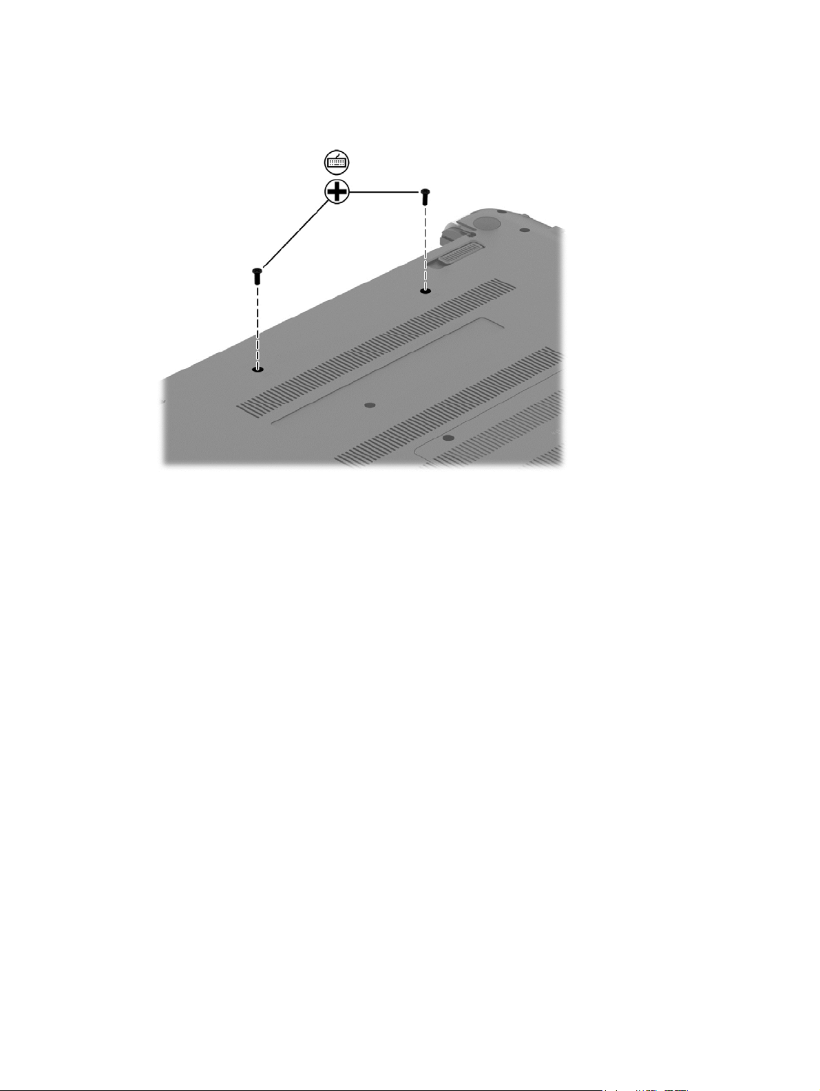
Remove the keyboard:
1. Remove the 2 Phillips M2.5×6.5 screws that secure the keyboard to the computer.
2. Rest the computer on its left side.
3. Open the computer.
64 Chapter 6 Removal and replacement procedures for Authorized Service Provider parts
Page 75
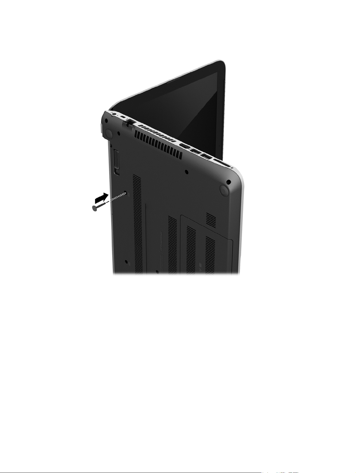
4. Insert a thin tool or a keyboard push tool into the left retention screw hole, and then press on
the back of the keyboard until the keyboard disengages from the computer.
5. Turn the computer right-side up with the front toward you.
Component replacement procedures
65
Page 76

6. Gently slide your finger along the top edge of the keyboard to release the keyboard clips (1). Lift
up the rear edge of the keyboard (2).
7. Swing the keyboard (1) up and forward until it rests upside down on the palm rest. Release
the ZIF connector (2) by lifting connector tab and then disconnecting the keyboard cable (3) from
the system board.
8. Remove the keyboard (4).
Reverse this procedure to install the keyboard.
66 Chapter 6 Removal and replacement procedures for Authorized Service Provider parts
Page 77

Top cover
NOTE: The top cover spare part kit includes the TouchPad and cable.
Description Spare part number
Aluminum with midnight black finish 734435-001
Flyer red finish 734431-001
Goji berry finish 736818-001
Hazel berry finish 736819-001
Mineral black finish 736817-001
Pearl white finish 734430-001
Raspberry finish 736820-001
Revolutionary blue finish 734432-001
Regal purple finish 734433-001
Sparkling black finish 734434-001
IMPORTANT: Make special note of each screw and screw lock size and location during removal
and replacement
Before removing the top cover, follow these steps:
1. Shut down the computer.
2. Disconnect all external devices connected to the computer.
3. Disconnect the power from the computer by first unplugging the power cord from the AC outlet
and then unplugging the AC adapter from the computer.
4. Remove the battery (see
a. Optical drive (see
b. Keyboard (see
c. Service door (see
d. WLAN module (see
e. Memory module (see
Battery on page 49), and then remove the following components:
Optical drive on page 55)
Keyboard on page 62)
Service door on page 50)
WLAN module on page 53)
Memory module on page 51)
Component replacement procedures
67
Page 78
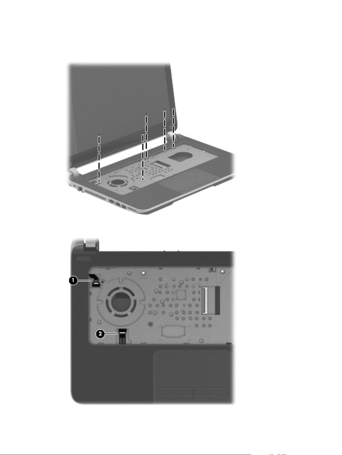
Remove the top cover:
1. Remove the 5 Phillips M2.5×3.0 screws that secure the top cover to the base enclosure.
2. Disconnect the power button cable (1) and the TouchPad cable (2).
68 Chapter 6 Removal and replacement procedures for Authorized Service Provider parts
Page 79
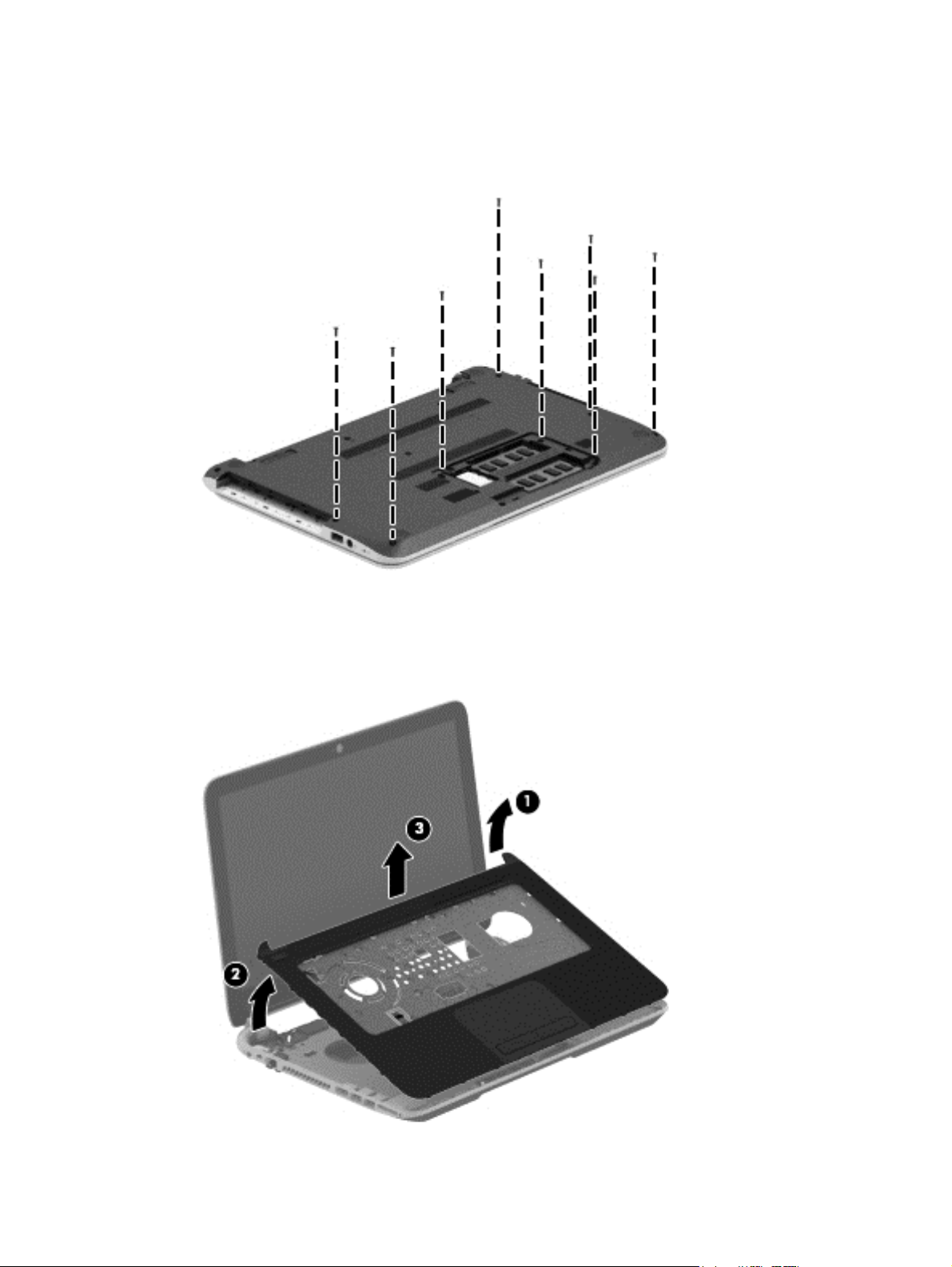
3. Close the display and turn the computer upside down.
4. Remove the 8 Phillips M2.5×6.5 screws from the bottom of the computer.
5. Turn the computer over and open the display.
6. Gently pull on the right upper corner (1) and lift around the edges of the top cover (2). Lift to
remove the top cover (3).
Component replacement procedures
69
Page 80

When replacing the top cover, be sure that the following components are removed from the defective
top cover and installed on the replacement top cover:
Power button board and cable (see
●
Touchpad button board (includes cable and buttons), (see
●
USB/audio board (instructions are included in the steps for removing the hard drive; see
●
Power button board on page 75)
TouchPad button board on page 77)
drive on page 71)
Reverse this procedure to install the top cover.
Hard
70 Chapter 6 Removal and replacement procedures for Authorized Service Provider parts
Page 81

Hard drive
NOTE: The hard drive spare part kit does not include the hard drive rubber bracket, hard drive
connector cable, or screws. These components are included in the Hard Drive Hardware Kit, spare part
number 740706-001.
Description Spare part number
1 TB, 5400 rpm, 9.5 mm 676521-005
750 GB, 5400 rpm, 9.5 mm 634250-005
500 GB, 5400 rpm, 7.0 mm 683802-005
mSATA solid-state drive, 24 GB (for use with select computer models with Intel processors, HM86
Express chipsets, and switchable discrete graphics)
732085-001
Before removing the hard drive, follow these steps:
1. Turn off the computer. If you are unsure whether the computer is off or in Hibernation, turn
the computer on, and then shut it down through the operating system.
2. Disconnect the power from the computer by unplugging the power cord from the computer.
3. Disconnect all external devices from the computer.
4. Remove the battery (see
a. Optical drive (see
b. Keyboard (see
c. Service door (see
d. WLAN module (see
e. Memory module (see
f. Top cover (see
Battery on page 49), and then remove the following components:
Optical drive on page 55)
Keyboard on page 62)
Service door on page 50)
WLAN module on page 53)
Memory module on page 51)
Top cover on page 67)
Component replacement procedures
71
Page 82
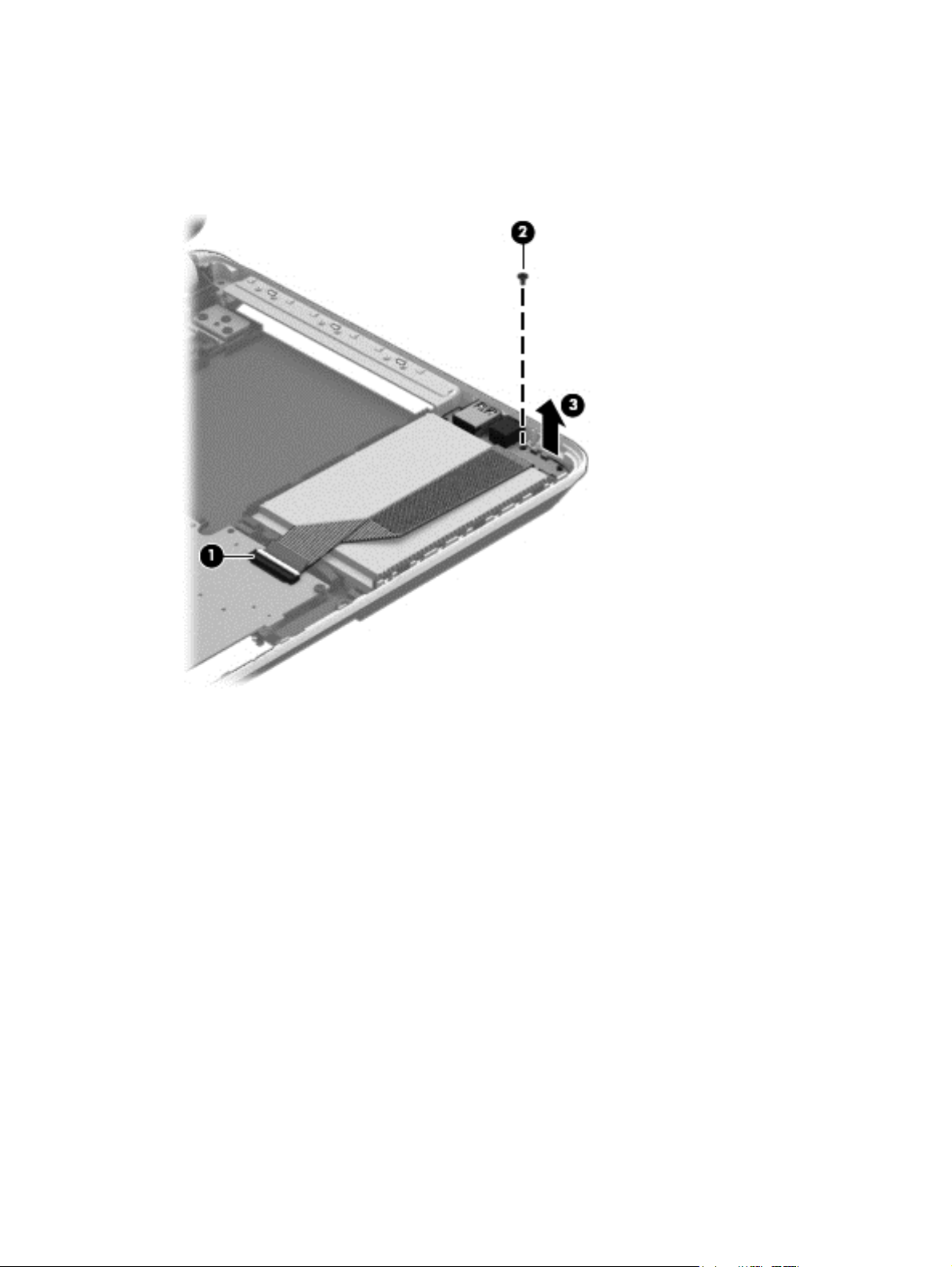
Remove the hard drive:
1. Disconnect the USB/audio cable (1) by flipping the connector and lifting the cable. Remove the
USB/audio cable Phillips M 2.5×3.0 screw (2) and then lift the USB/audio board (3). The USB/
audio board spare part number is 734417-001.
72 Chapter 6 Removal and replacement procedures for Authorized Service Provider parts
Page 83

2. Lift up the front of the hard drive (1), and then move the hard drive (2) forward.
Component replacement procedures
73
Page 84

3. Disconnect the hard drive connector cable from the hard drive.
4. If it is necessary to disassemble the hard drive, perform the following steps:
a. Remove the four Phillips M3.0×3.5 screws (1) from the bracket.
b. Remove the bracket (2) from the hard drive.
Reverse this procedure to reassemble and install the hard drive.
74 Chapter 6 Removal and replacement procedures for Authorized Service Provider parts
Page 85

Power button board
Description Spare part number
Power button board (includes cable) 734416-001
Before removing the power button board, follow these steps:
1. Turn off the computer. If you are unsure whether the computer is off or in Hibernation, turn
the computer on, and then shut it down through the operating system.
2. Disconnect the power from the computer by unplugging the power cord from the computer.
3. Disconnect all external devices from the computer.
4. Remove the battery (see
a. Optical drive (see
b. Service door (see
c. Keyboard (see
d. WLAN module (see
e. Memory module (see
f. Top cover (see
Battery on page 49), and then remove the following components:
Optical drive on page 55)
Service door on page 50)
Keyboard on page 62)
WLAN module on page 53)
Memory module on page 51)
Top cover on page 67)
Remove the power button board:
1. Turn the top cover upside down, with the front toward you.
2. Remove the Phillips PM2.5×2.5 screw (1) that secures the power button board to the top cover.
Component replacement procedures
75
Page 86

3. Remove the power button board (2) with cable (the cable was disconnected when removing the
top cover).
Reverse this procedure to install the power button board.
76 Chapter 6 Removal and replacement procedures for Authorized Service Provider parts
Page 87

TouchPad button board
Description Spare part number
TouchPad button board (includes cable) 734418-001
Before removing the TouchPad button board, follow these steps:
1. Turn off the computer. If you are unsure whether the computer is off or in Hibernation, turn
the computer on, and then shut it down through the operating system.
2. Disconnect the power from the computer by unplugging the power cord from the computer.
3. Disconnect all external devices from the computer.
4. Remove the battery (see
a. Optical drive (see
b. Service door (see
c. WLAN module (see
d. Memory module (see
e. Keyboard (see
f. Top cover (see
Battery on page 49), and then remove the following components:
Optical drive on page 55)
Service door on page 50)
WLAN module on page 53)
Memory module on page 51)
Keyboard on page 62)
Top cover on page 67)
Remove the TouchPad button board:
1. Turn the top cover upside down, with the front toward you.
2. Release the TouchPad ZIF connector, and then disconnect the TouchPad button board cable (1)
from the TouchPad board.
3. Remove the 3 Phillips PM2.0×3.5 screws (2) that secures the TouchPad button board bracket to
the top cover.
4. Remove the TouchPad button board (3) carefully lifting the cable from the guides (the cable was
disconnected when removing the top cover).
5. Lift up the TouchPad button board (4).
Component replacement procedures
77
Page 88
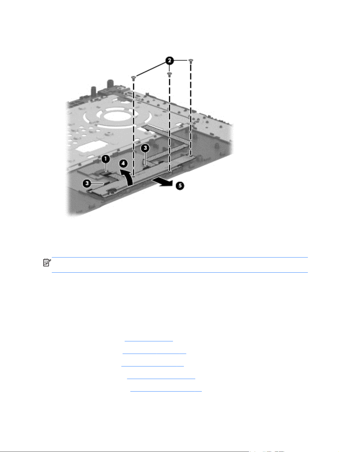
6. Remove the TouchPad button board (5).
Reverse this procedure to install the TouchPad button board.
Optical drive connector cable
NOTE: The optical drive connector cable is included with the Optical Drive, spare part number
734415-001.
Before removing the optical drive connector cable, follow these steps:
1. Turn off the computer. If you are unsure whether the computer is off or in Hibernation, turn
the computer on, and then shut it down through the operating system.
2. Disconnect the power from the computer by unplugging the power cord from the computer.
3. Disconnect all external devices from the computer.
4. Remove the battery (see
a. Optical drive (see
b. Service door (see
c. WLAN module (see
d. Memory module (see
Battery on page 49), and then remove the following components:
Optical drive on page 55)
Service door on page 50)
WLAN module on page 53)
Memory module on page 51)
78 Chapter 6 Removal and replacement procedures for Authorized Service Provider parts
Page 89

e. Keyboard (see Keyboard on page 62)
f. Top cover (see
Remove the optical drive connector cable:
1. Disconnect the optical drive connector cable (1) from the system board.
2. Release the optical drive connector cable from the clip (2) built into the base enclosure.
3. Remove the optical drive connector cable.
Top cover on page 67)
Reverse this procedure to install the optical drive connector cable.
Component replacement procedures
79
Page 90

System board
NOTE: The system board spare part kit includes replacement thermal material.
Description Spare part number
For computer models equipped with Intel processors and UMA graphics
4th generation
Intel Core i5-4200U 1.6 GHz processor (3.0 MB L3 cache, 15 W) for use with FreeDOS and
Ubuntu
Intel Core i5-4200U 1.6 GHz processor (3.0 MB L3 cache, 15 W) for use with Windows
Standard
Intel Core i5-4200U 1.6 GHz processor (3.0 MB L3 cache, 15 W) for use with Windows
Professional
Intel Core i3-4005U 1.7 GHz processor (3.0 MB L3 cache, 15 W) for use with FreeDOS and
Ubuntu
Intel Core i3-4005U 1.7 GHz processor (3.0 MB L3 cache, 15 W) for use with Windows
Standard
Intel Core i3-4005U 1.7 GHz processor (3.0 MB L3 cache, 15 W) for use with Windows
Professional
For computer models equipped with Intel processors and UMA graphics
3rd generation
Pentium 2117U HM76 (1.8 GHz, 2 MB L3 Cache, 1600 MHz DDR3, 17 W) for use with
FreeDOS and Ubuntu
734423-001
734423-501
734423-601
734424-001
734424-501
734424-601
738148-001
Pentium 2117U HM76 (1.8 GHz, 2 MB L3 Cache, 1600 MHz DDR3, 17 W) for use with
Windows Standard
Pentium 2117U HM76 (1.8 GHz, 2 MB L3 Cache, 1600 MHz DDR3, 17 W) for use with
Windows Professional
Core i3-3217U (1. 8GHz, 3 MB L3 Cache, 1600 MHz DDR3, 17 W) for use with FreeDOS and
Ubuntu
Core i3-3217U (1.8 GHz, 3 MB L3 Cache, 1600 MHz DDR3, 17 W) for use with Windows
Standard
Core i3-3217U (1.8 GHz, 3 MB L3 Cache, 1600 MHz DDR3, 17 W) for use with Windows
Professional
For computer models equipped with Intel processors and switchable discrete
graphics
4th generation
NVIDIA N14P-GV2 GeForce GT 740M 2 GB graphics and Intel Core i7-4500U (1.8 GHz DC,
15 W) for use with FreeDOS and Ubuntu
NVIDIA N14P-GV2 GeForce GT 740M 2 GB graphics and Intel Core i7-4500U (1.8 GHz DC,
15 W) for use with Windows Standard
738148-501
738148-601
738150-001
738150-501
738150-601
738154-001
738154-501
80 Chapter 6 Removal and replacement procedures for Authorized Service Provider parts
Page 91

Description Spare part number
NVIDIA N14P-GV2 GeForce GT 740M 2 GB graphics and Intel Core i7-4500U (1.8 GHz DC,
15 W) for use with Windows Professional
NVIDIA N14P-GV2 GeForce GT 740M 2 GB graphics and Intel Core i5-4200U (1.6 GHz DC,
15 W) for use with FreeDOS and Ubuntu
NVIDIA N14P-GV2 GeForce GT 740M 2 GB graphics and Intel Core i5-4200U (1.6 GHz DC,
15 W) for use with Windows Standard
NVIDIA N14P-GV2 GeForce GT 740M 2 GB graphics and Intel Core i5-4200U (1.6 GHz DC,
15 W) for use with Windows Professional
AMD Radeon 8670M 2 GB graphics and Intel Core i7-4500U (1.8 GHz DC, 15 W) for use with
FreeDOS and Ubuntu
AMD Radeon 8670M 2 GB graphics and Intel Core i7-4500U (1.8 GHz DC, 15 W) for use with
Windows Standard
AMD Radeon 8670M 2 GB graphics and Intel Core i7-4500U (1.8 GHz DC, 15 W) for use with
Windows Professional
AMD Radeon 8670M 2 GB graphics and Intel Core i5-4200U (1.6 GHz, DC 15 W) for use with
FreeDOS and Ubuntu
AMD Radeon 8670M 2 GB graphics and Intel Core i5-4200U (1.6 GHz, DC 15 W) for use with
Windows Standard
AMD Radeon 8670M 2 GB graphics and Intel Core i5-4200U (1.6 GHz, DC 15 W) for use with
Windows Professional
738154-601
738156-001
738156-501
738156-601
734429-001
734429-501
734429-601
734429-001
734426-501
734426-601
AMD Radeon 8670M 1 GB graphics and Intel Core i3-4005U (1.7 GHz, DC 15 W) for use with
FreeDOS and Ubuntu
AMD Radeon 8670M 1 GB graphics and Intel Core i3-4005U (1.7 GHz, DC 15 W) for use with
Windows Standard
AMD Radeon 8670M 1 GB graphics and Intel Core i3-4005U (1.7 GHz, DC 15 W) for use with
Windows Professional
For computer models equipped with Intel processors and switchable discrete
graphics
3rd generation
AMD Radeon 8670M 2 GB graphics and Intel Core i3-3217U (1.8 GHz, L3 Cache, 1600 MHz
DDR3, 17 W) for use with FreeDOS and Ubuntu
AMD Radeon 8670M 2 GB graphics and Intel Core i3-3217U (1.8 GHz, L3 Cache, 1600 MHz
DDR3, 17 W) for use with Windows Standard
AMD Radeon 8670M 2 GB graphics and Intel Core i3-3217U (1.8 GHz, L3 Cache, 1600 MHz
DDR3, 17 W) for use with Windows Professional
For computer models equipped with AMD processors and UMA graphics
AMD A4-5000 (1.5 GHz, 2 MB L2, 1600 MHz DDR3L, quad core, 15 W) for use with FreeDOS
and Ubuntu
AMD A4-5000 (1.5 GHz, 2 MB L2, 1600 MHz DDR3L, quad core, 15 W) for use with Windows
Standard
734427-001
734427-501
734427-601
738152-001
738152-501
738152-601
734443-001
734443-501
Component replacement procedures
81
Page 92

Description Spare part number
AMD A76M chipset, A6-4455M processor (2.6 GHz/2.1 GHz, 2 MB L2, 1333 MHz DDR3L
dual core, 19 W) for use with FreeDOS and Ubuntu
AMD A76M chipset, A6-4455M processor (2.6 GHz/2.1 GHz, 2 MB L2, 1333 MHz DDR3L
dual core, 19 W) for use with Windows Standard
AMD A6-5200 (2.6 GHz/2.1 GHz, 2 MB L2, 1600 MHz DDR3L, dual core, 17 W) for use with
FreeDOS and Ubuntu
AMD A6-5200 (2.6 GHz/2.1 GHz, 2 MB L2, 1600 MHz DDR3L, dual core, 17 W) for use with
Windows Standard
AMD A8-5545M A76M (2.7 GHz/1.7 GHz, 4 MB L2, 1333 MHz DDR3L quad core, 19 W) for
use with FreeDOS and Ubuntu
AMD A8-5545M A76M (2.7 GHz/1.7 GHz, 4 MB L2, 1333 MHz DDR3L quad core, 19 W) for
use with Windows Standard
AMD A76M chipset, A8-4555M processor (2.4 GHz/1.6 GHz, 4 MB L2, 1333 MHz DDR3L
quad core, 19 W) for use with FreeDOS and Ubuntu
AMD A76M chipset, A8-4555M processor (2.4 GHz/1.6 GHz, 4 MB L2, 1333 MHz DDR3L
quad core, 19 W) for use with Windows Standard
AMD E2-3000 (1.65 GHz, 1 MB L2, 1600 MHz DDR3L, dual core, 15 W) for use with FreeDOS
and Ubuntu
AMD E2-3000 (1.65 GHz, 1 MB L2, 1600 MHz DDR3L, dual core, 15 W) for use with Windows
Standard
736821-001
736821-501
734444-001
734444-501
734446-001
734446-501
736822-001
736822-501
734447-001
734447-501
For computer models equipped with AMD processors and switchable discrete
graphics
AMD Radeon 8670M 1 GB graphics and A6-5200 processor (2.6 GHz/2.1 GHz, 2 MB L2,
1600 MHz DDR3L, dual core, 17 W) for use with FreeDOS and Ubuntu
AMD Radeon 8670M 1 GB graphics and A6-5200 processor (2.6 GHz/2.1 GHz, 2 MB L2,
1600 MHz DDR3L, dual core, 17 W) for use with Windows Standard
AMD Radeon 8670M 2 GB graphics and A10-5745M processor (2.9 GHz/2.1 GHz, 4 MB L2,
1333 MHz DDR3L quad core, 25 W) for use with FreeDOS and Ubuntu
AMD Radeon 8670M 2 GB graphics and A10-5745M processor (2.9 GHz/2.1 GHz, 4 MB L2,
1333 MHz DDR3L quad core, 25 W) for use with FreeDOS and Ubuntu
734440-001
734440-501
734441-001
734441-001
Before removing the system board, follow these steps:
1. Turn off the computer. If you are unsure whether the computer is off or in Hibernation, turn
the computer on, and then shut it down through the operating system.
2. Disconnect the power from the computer by unplugging the power cord from the computer.
82 Chapter 6 Removal and replacement procedures for Authorized Service Provider parts
Page 93

3. Disconnect all external devices from the computer.
4. Remove the battery (see
a. Optical drive (see
b. Service door (see
c. WLAN module (see
d. Memory module (see
e. Keyboard (see
f. Top cover (see
g. Hard drive (see
When replacing the system board, be sure that the following components are removed from
the defective system board and installed on the replacement system board:
Hard drive connector cable
●
Power connector cable (see
●
RTC battery (see
●
Fan (see
●
Fan on page 89)
RTC battery on page 87)
Battery on page 49), and then remove the following components:
Optical drive on page 55)
Service door on page 50)
WLAN module on page 53)
Memory module on page 51)
Keyboard on page 62)
Top cover on page 67)
Hard drive on page 71)
Power connector cable on page 95)
Heat sink assembly (see
●
Remove the system board:
1. Disconnect the following cables from the system board:
Display panel cable (1)
●
Speaker cable (2)
●
Heat sink assembly on page 91)
Component replacement procedures
83
Page 94
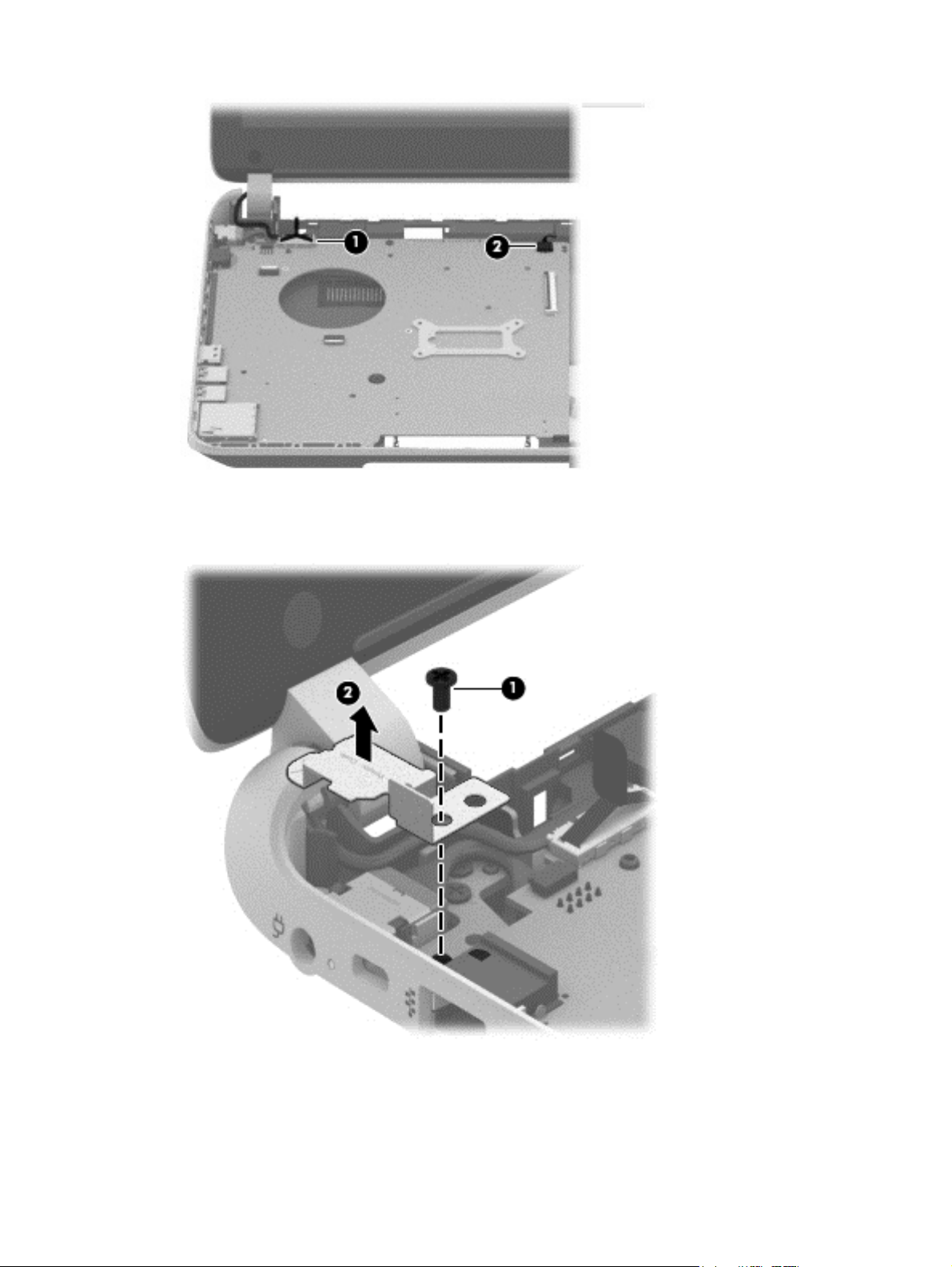
2. Remove the Phillips PM2.5×6.5 screw (1) that secures the power connector bracket to
the base enclosure. Remove the power connector bracket (2).
3. Remove the 2 Phillips M2.5×5.0 screws (1) that secure the system board to the base enclosure.
4. Lift the right side of the system board (2) until it rests at an angle.
84 Chapter 6 Removal and replacement procedures for Authorized Service Provider parts
Page 95
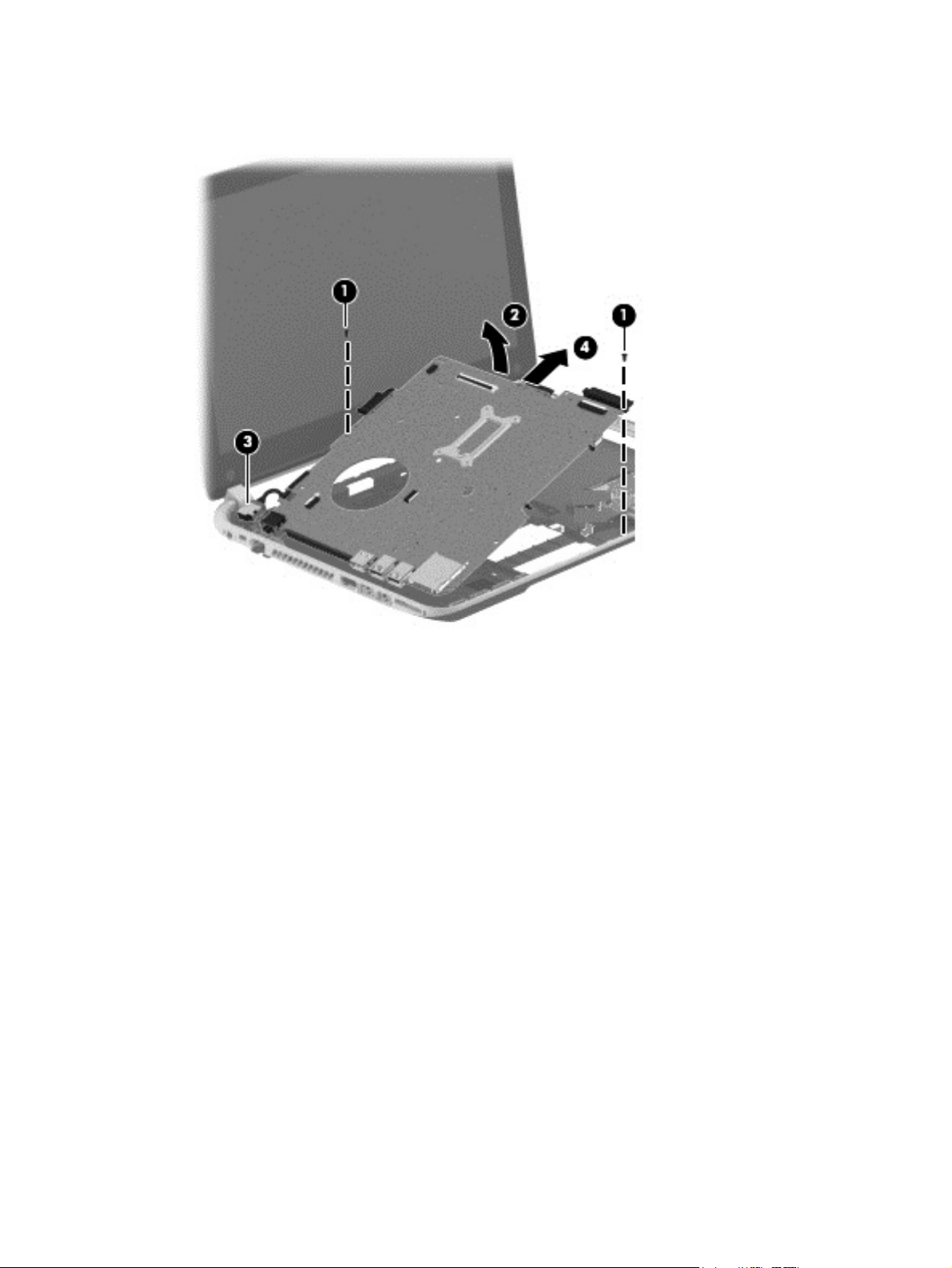
5. Carefully remove from the power connector (3). Remove the system board (4) by sliding it up
and to the right at an angle.
6. Remove the hard drive connector cable:
a. Turn the system board upside down, with the front toward you.
Component replacement procedures
85
Page 96

b. Disconnect the hard drive connector cable from the system board. The hard drive cable is
part of the Hard Drive Hardware Kit, part number 740706-001.
Reverse this procedure to install the system board.
86 Chapter 6 Removal and replacement procedures for Authorized Service Provider parts
Page 97

RTC battery
Description Spare part number
RTC battery 697917-001
Before removing the RTC battery, follow these steps:
1. Turn off the computer. If you are unsure whether the computer is off or in Hibernation, turn
the computer on, and then shut it down through the operating system.
2. Disconnect the power from the computer by unplugging the power cord from the computer.
3. Disconnect all external devices from the computer.
4. Remove the battery (see
a. Optical drive (see
b. Service door (see
c. Remove the WLAN module (see
d. Remove the Memory module (see
e. Keyboard (see
f. Top cover (see
g. Hard drive (see
h. System board (see
Battery on page 49), and then remove the following components:
Optical drive on page 55)
Service door on page 50)
WLAN module on page 53)
Memory module on page 51)
Keyboard on page 62)
Top cover on page 67)
Hard drive on page 71)
System board on page 80)
Remove the RTC battery:
1. Turn the system board upside down, with the front toward you.
2. Use a flat-bladed, non-metallic tool (1) to release the RTC battery from the socket on the
system board. The battery is spring loaded and will pop up.
Component replacement procedures
87
Page 98

3. Remove the RTC battery (2).
Reverse this procedure to install the RTC battery. When installing the RTC battery, make sure the “+”
sign faces up.
88 Chapter 6 Removal and replacement procedures for Authorized Service Provider parts
Page 99

Fan
Description Spare part number
Fan 732068-001
NOTE: To properly ventilate the computer, allow at least 7.6 cm (3 in) of clearance on the left side of
the computer. The computer uses an electric fan for ventilation. The fan is controlled by a temperature
sensor and is designed to turn on automatically when high temperature conditions exist. These
conditions are affected by high external temperatures, system power consumption, power
management/battery conservation configurations, battery fast charging, and software requirements.
Exhaust air is displaced through the ventilation grill located on the left side of the computer.
Before removing the fan, follow these steps:
1. Turn off the computer. If you are unsure whether the computer is off or in Hibernation, turn
the computer on, and then shut it down through the operating system.
2. Disconnect the power from the computer by unplugging the power cord from the computer.
3. Disconnect all external devices from the computer.
4. Remove the battery (see
a. Optical drive (see
b. Service door (see
c. WLAN module (see
d. Memory module (see
e. Keyboard (see
f. Top cover (see
g. Hard drive (see
h. System board (see
Battery on page 49), and then remove the following components:
Optical drive on page 55)
Service door on page 50)
WLAN module on page 53)
Memory module on page 51)
Keyboard on page 62)
Top cover on page 67)
Hard drive on page 71)
System board on page 80)
Remove the fan:
1. Turn the system board upside down, with the front toward you.
2. Disconnect the fan cable (1) from the system board.
3. Remove the 2 screws (2) that secure the fan to the system board.
Component replacement procedures
89
Page 100

4. Remove the fan (3) from the system board.
Reverse this procedure to install the fan.
90 Chapter 6 Removal and replacement procedures for Authorized Service Provider parts
 Loading...