

Page 1

HP
P4800 G2 SAN Solution for BladeSystem
Maintenance Guide
Abstract
This guide explains how to back up, restore, upgrade, and otherwise maintain the HP P4800 G2 SAN Solution for BladeSystem.
The intended audience is system administrators and technicians with experience managing and repairing networked storage.
For installation and configuration information, see the HP P4800 G2 SAN Solution for BladeSystem Quick Start Guide. For
day-to-day operations, see the HP P4000 SAN Solution User Guide. For late-breaking information, HP recommends that you
read the release notes for the installed software version.
Obtain the latest version of this and other HP P4000 user documents by navigating to the Manuals page of the HP Business
Support Center website:
www.hp.com/support/manuals
In the Storage section, select Disk Storage Systems and then select HP P4000 G2 SAN Solutions.
HP Part Number: AX696-96151
Published: September 2011
Edition: 4
Page 2

© Copyright 2010, 2011 Hewlett-Packard Development Company, L.P.
The information contained herein is subject to change without notice. The only warranties for HP products and services are set forth in the express
warranty statements accompanying such products and services. Nothing herein should be construed as constituting an additional warranty. HP shall
not be liable for technical or editorial errors or omissions contained herein.
Acknowledgments
Microsoft® Windows® is a U.S. registered trademark of Microsoft Corporation.
Warranty
To obtain a copy of the warranty for this product, see the warranty information website:
http://www.hp.com/go/storagewarranty
Revision History
July 2010Revision 1
First edition
November 2010Revision 2
Second edition—Updated with changes for the SAN/iQ software 9.0 release.
March 2011Revision 3
Third edition—Applied branding changes to product and server blade names. The product name changed from P4000 BladeSystem for SAN
Solutions to P4000 G2 SAN Solution for BladeSystem. The server blade changed from the BL460c G6 to the BL460c G7 (G2 server blade). The
G2 server blade name is P4460sb.
September 2011Revision 4
Fourth edition—Changed Quick Restore references from a CD to an .iso image.
Page 3

Contents
1 Overview..................................................................................................5
Hardware components..............................................................................................................5
Hardware configuration.............................................................................................................5
Documentation available...........................................................................................................9
2 Backing up HP P4800 G2 solution configurations.........................................11
Backing up or restoring the Virtual Connect domain configuration.................................................11
Backing up the SAS switch.......................................................................................................12
Backing up remaining HP P4800 G2 solution configurations........................................................12
3 Maintaining the HP P4800 G2 solution.......................................................13
Troubleshooting......................................................................................................................13
Locating the HP P4800 G2 solution warranty entitlement labels....................................................13
Performing field system recovery of the HP P4800 G2 solution......................................................14
Repairing a storage system......................................................................................................17
Upgrading SAN/iQ software...................................................................................................18
Adding capacity to an existing P4800 G2 SAN.........................................................................18
Upgrading firmware................................................................................................................18
4 Removing and replacing the HP P4800 G2 solution components....................20
Additional component removal and replacement instructions........................................................20
Identifying hot pluggable and non-hot pluggable components......................................................20
Replacing the server blade and server blade components............................................................20
Replacing the controller and controller components.....................................................................22
Replacing the VC Flex-10 module..............................................................................................24
Replacing the SAS switch.........................................................................................................24
Replacing a SAS cable............................................................................................................25
Replacing the disk enclosure I/O module...................................................................................26
Replacing the disk enclosure power supply.................................................................................26
Replacing the disk enclosure fan...............................................................................................26
Replacing the disk enclosure hard drive.....................................................................................27
5 Support and other resources......................................................................28
Contacting HP........................................................................................................................28
HP Insight Remote Support software..........................................................................................28
Related information.................................................................................................................29
Rack stability..........................................................................................................................30
Customer self repair................................................................................................................30
A HP P4800 G2 solution cabling..................................................................31
B Regulatory compliance notices...................................................................35
Regulatory compliance identification numbers............................................................................35
Federal Communications Commission notice..............................................................................35
Canadian notice (Avis Canadien).............................................................................................36
European Union notice............................................................................................................36
Japanese notices....................................................................................................................37
Korean notices.......................................................................................................................37
Taiwanese notices...................................................................................................................38
Turkish recycling notice............................................................................................................38
Laser compliance notices.........................................................................................................39
Recycling notices....................................................................................................................41
Contents 3
Page 4

Battery replacement notices.....................................................................................................46
Glossary....................................................................................................50
Index.........................................................................................................51
4 Contents
Page 5

1 Overview
The HP P4800 G2 SAN Solution for BladeSystem (HP P4800 G2 solution) base configuration is
a 2-node SAN consisting of two server blades and one disk enclosure. The server blades run the
SAN/iQ software, and the disk enclosure contains 70 disks. Up to six server blades and three
disk enclosures can be added, for a total of eight blades and four disk enclosures in an 8-node
SAN.
Multiple HP P4800 G2 solutions can be combined into clusters or management groups as part of
the same SAN.
NOTE: In this solution, storage system corresponds to a server blade. There are up to eight
storage systems in the HP P4800 G2 solution.
Hardware components
The HP P4800 G2 solution comprises the following components:
• HP BladeSystem c7000 Enclosure (1)
• Server blades (2 to 8)
• HP 3G SAS BL Switches (2, pass-through modules between the blade enclosure and the disk
enclosures)
• HP disk enclosures (1 per pair of server blades)
• HP Smart Array P700m controller cards (one on each server blade)
• HP VC Flex-10 modules (2, these modules connect to your network)
NOTE: Note: The original P4800 solution uses the HP 4000sb server blade. All information in
this guide applies to both the original and G2 solutions and server blades.
Hardware configuration
Figure 1 (page 6) shows the base configuration of the HP P4800 G2 solution. Figure 2 (page 7)
through Figure 4 (page 9) show additional configurations of the HP P4800 G2 solution.
Hardware components 5
Page 6
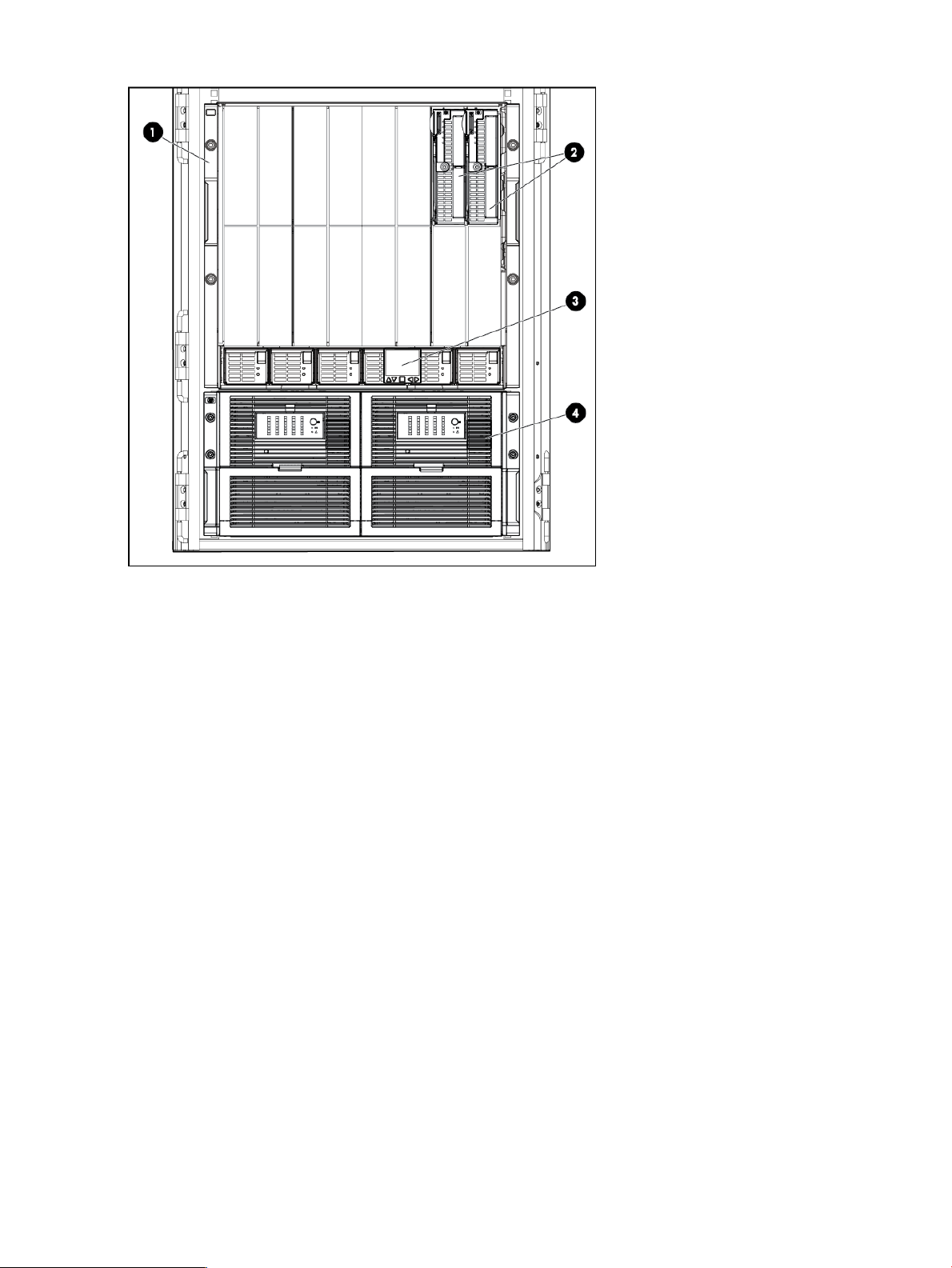
Figure 1 Front view: HP P4800 G2 solution 2 node
1. Blade enclosure (1)
2. Server blades (2)
3. HP BladeSystem Insight Display (1)
4. Disk enclosure (1)
6 Overview
Page 7
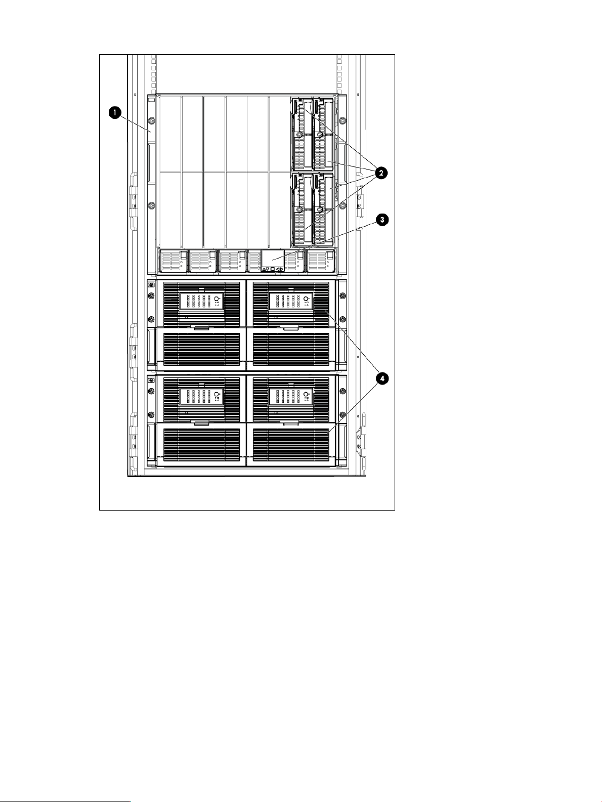
Figure 2 Front view: HP P4800 G2 solution 4 node
1. Blade enclosure (1)
2. Sever blades (4)
3. HP BladeSystem Insight Display (1)
4. Disk enclosures (2)
Hardware configuration 7
Page 8
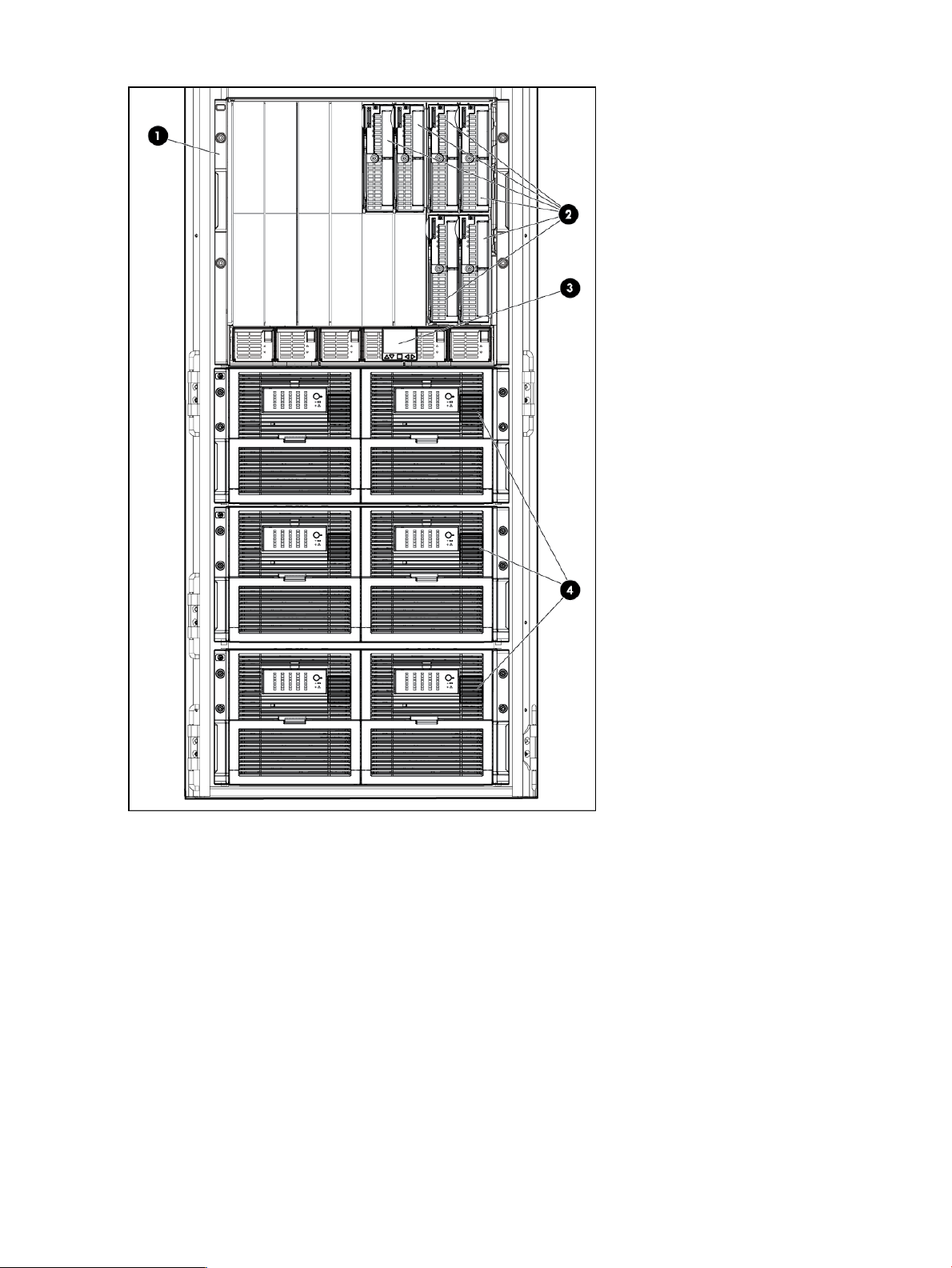
Figure 3 Front view: HP P4800 G2 solution 6 node
1. Blade enclosure (1)
2. Server blades (6)
3. HP BladeSystem Insight Display (1)
4. Disk enclosures (3)
8 Overview
Page 9
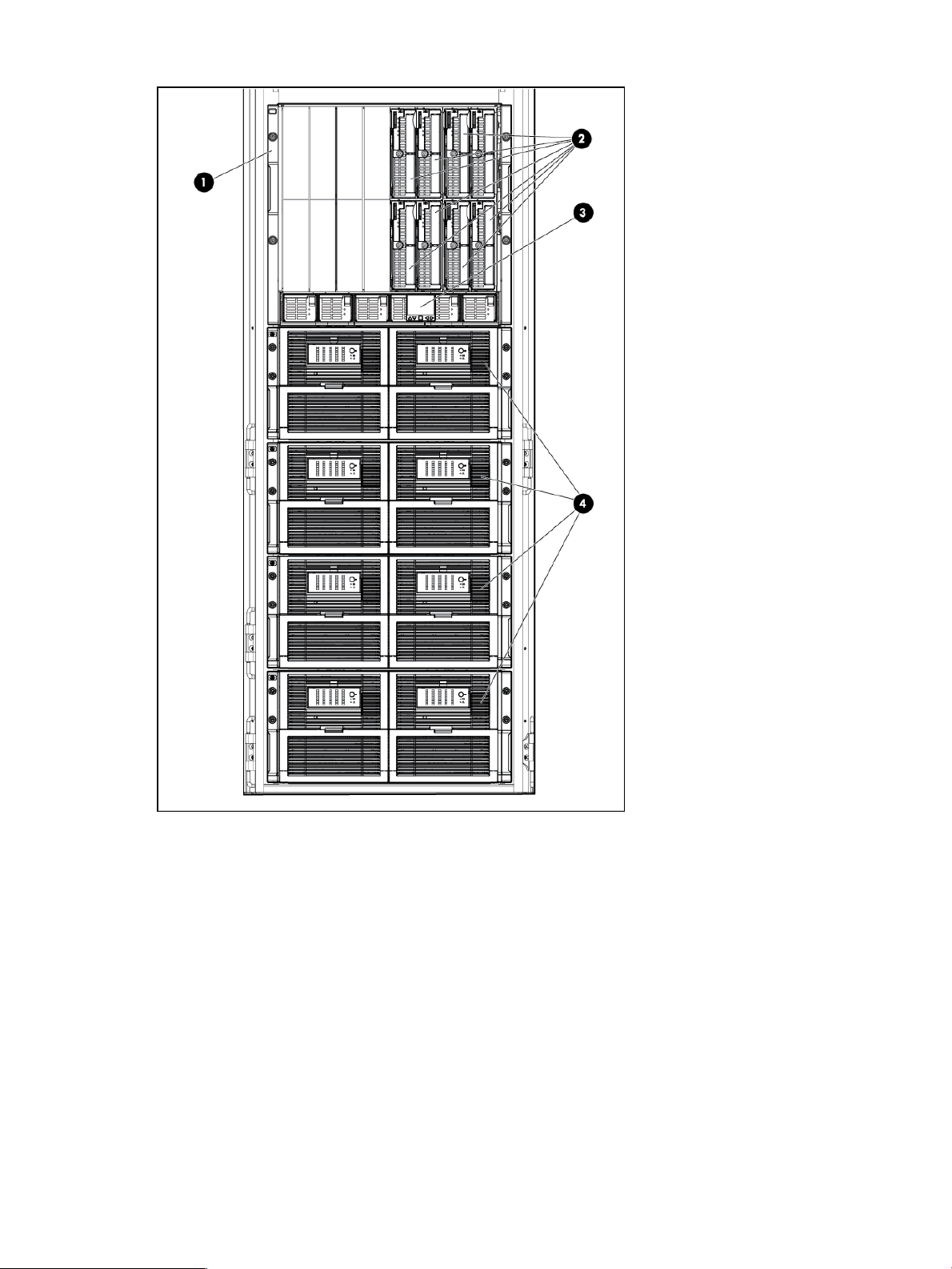
Figure 4 Front view: HP P4800 G2 solution 8 node
1. Blade enclosure (1)
2. Server blades (8)
3. HP BladeSystem Insight Display (1)
4. Disk enclosures (4)
Documentation available
For quick installation and setup, see the HP P4800 G2 SAN Solution for BladeSystem Quick Start
Guide.
For links to the latest manuals for HP BladeSystem and other components, see the HP P4800 G2
SAN Solution for BladeSystem Documentation CD.
For detailed instructions about using the HP P4800 G2 SAN Solution for BladeSystem, see the
following resources:
Documentation available 9
Page 10

• Online Help in the Centralized Management Console
Click Help→Help Topics from the menu bar to open the Online Help. Context-sensitive help is
available by clicking the question mark on any window.
• HP P4000 SAN Solution User Guide
Find complete instructions for configuring and managing storage systems and clustered storage
volumes in the User Guide. The User Guide is available in PDF format, installed in the same
directory as the Centralized Management Console program files.
• HP P4000 VSA Installation and Configuration Guide
Find detailed instructions for planning and installing the VSA and getting started with the
Centralized Management Console.
• HP P4000 Remote Copy User Guide
Find information about configuring and using asynchronous replication of storage volumes
and snapshots across geographic distances.
• HP P4000 Multi-Site HA/DR Solution Pack User Guide
Find detailed instructions for designing and implementing the Multi-Site SAN features to
synchronously and automatically mirror data between geographic sites.
• HP P4000 Software Release Notes
Review the Release Notes for the latest information about the product.
The latest versions of these documents, including localized versions, can be found by browsing to
http://www.hp.com/support/manuals. In the Storage section, click Disk Storage Systems and
then select HP P4000 G2 SAN Solutions.
For detailed conguration information related to the HP P4800 G2 solution in Virtual Desktop
Infrastructure (VDI) configurations, see the HP Converged Infrastructure Reference Architecture for
VMware View at http://www.hp.com/go/vdi.
10 Overview
Page 11
2 Backing up HP P4800 G2 solution configurations
HP recommends that you back up all HP P4800 G2 solution components for safekeeping after
initially powering on the HP P4800 G2 solution, and immediately after making changes to an
existing configuration or replacing a component. You must back up each component (for example,
the VC Flex-10 module) separately.
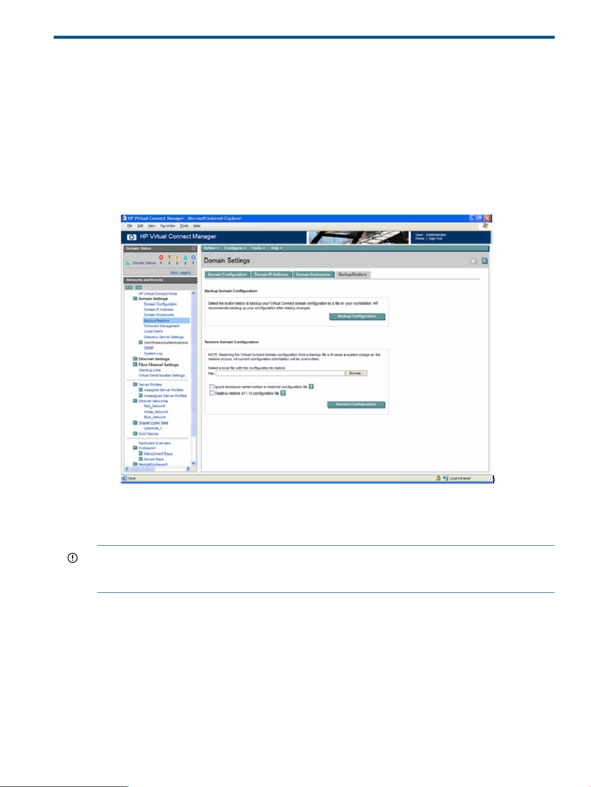
Backing up or restoring the Virtual Connect domain configuration
Use the Virtual Connect Manager to back up the VC Flex-10 module configuration.
1. From Onboard Administrator, go to the Virtual Connect Manager, Domain Settings
Backup/Restore pane.
2. Click Backup Configuration.
3. Navigate to the hard drive location for the backup file.
4. Name the file (usually the domain name), and then click Save.
IMPORTANT: Virtual Connect Manager cannot use backup configurations created with previous
versions of Virtual Connect Manager. For example, if you are currently using 2.01, you cannot
use a backup configuration that was created using 1.20.
To restore a domain configuration:
1. Browse to the backup file.
2. Select the file.
3. Select Ignore enclosure serial number in restored configuration file to restore a configuration
that was generated on another enclosure. If this item is not selected, a configuration generated
on another enclosure is rejected.
4. Select Disallow restore of 1.1x configuration file to restore the firmware to a revision other
than what is stored in the configuration file.
5. Click Restore Configuration.
6. Confirm the domain configuration to be restored, and then click OK.
Backing up or restoring the Virtual Connect domain configuration 11
Page 12
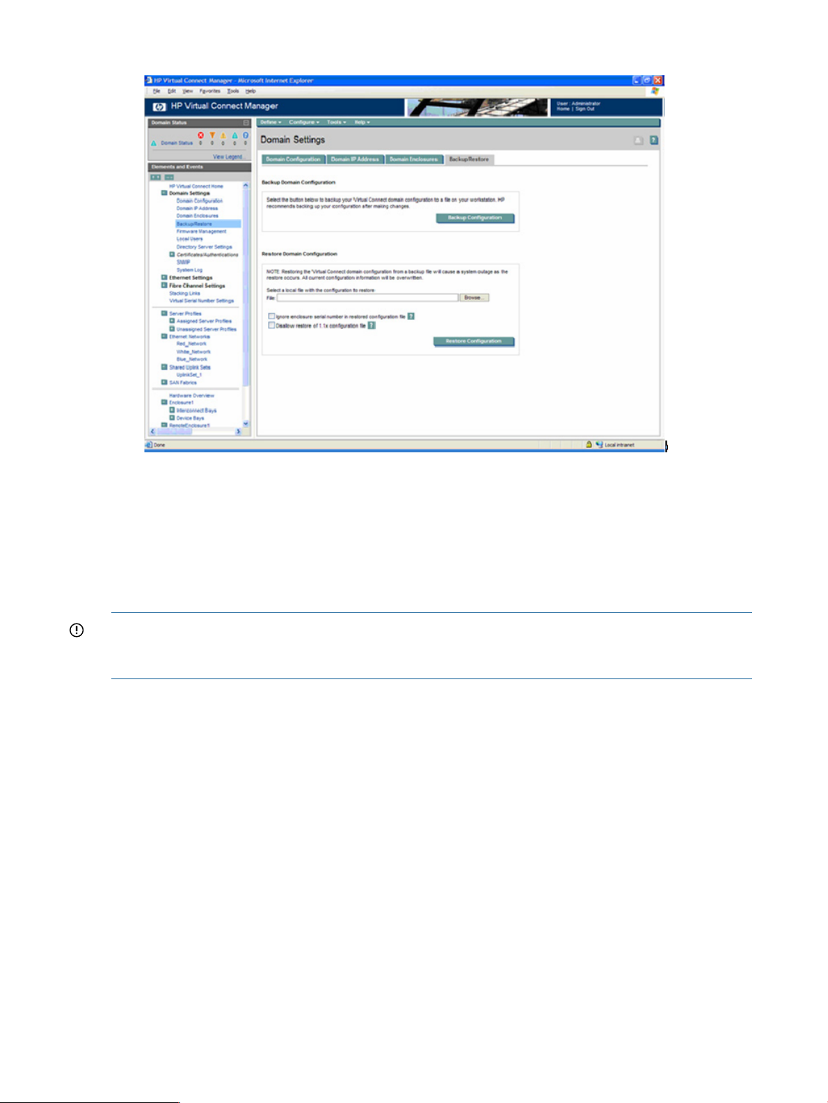
Figure 5 Virtual Connect Manager Domain Settings
Backing up the SAS switch
The SAS switch configuration cannot be backed up using the CMC. If you are replacing one SAS
switch, duplicate the configuration from the other switch. If you are replacing both SAS switches,
you must restore the configuration from a backup captured using the VSM CLI. For information
about backing up and restoring the SAS configuration using the CLI, see the HP Virtual SAS
Manager User Guide.
IMPORTANT: HP recommends that you not change the SAS zoning on the SAS switches or the
cabling between the SAS switches and the disk enclosures. See “HP P4800 G2 solution cabling”
(page 31) for the recommended cabling.
Backing up remaining HP P4800 G2 solution configurations
The following methods may be used to back up the remaining HP P4800 G2 solution configurations:
• Use your own system backup utility to back up data.
• Back up the configuration to an FTP server.
12 Backing up HP P4800 G2 solution configurations
Page 13
3 Maintaining the HP P4800 G2 solution
This chapter provides information to troubleshoot, upgrade, and recover the HP P4800 G2 solution.
Troubleshooting
For detailed troubleshooting information about the HP P4800 G2 solution components, see the
documents listed in Table 1 (page 13).
Table 1 Component troubleshooting information
ResourceComponent
HP ProLiant BL460c G7 Server Blade User GuideHP 4460sb G2 server blade
HP ProLiant Servers Troubleshooting Guide
HP ProLiant BL460c G6 Server Blade User GuideHP 4000sb server blade
HP ProLiant Servers Troubleshooting Guide
HP Smart Array Controllers for HP ProLiant Servers User Guide.HP Smart Array P700m controller
HP 3Gb SAS BL Switch user guideHP 3Gb SAS BL switch
HP 600 Modular Disk System Maintenance and Service GuideDisk enclosure
HP BladeSystem c-Class Enclosure Troubleshooting GuideBlade enclosure
CMC does not detect drives
Symptom
• The server blade will not boot the CMC, or the CMC does not list the storage drives or OS
boot drives.
Cause
• The BIOS was reset to factory defaults.
Resolution
Reset the BIOS by selecting Onboard P410i as the boot controller.
1. Restart the server blade, upon power on, press F9 to enter BIOS setup menu.
2. Select Boot Controller Order.
3. Select Ctrl:2 PCI Embedded HP Smart Array P410i controller.
4. Select Controller Order 1.
5. To exit the submenu, press Esc.
6. To exit the setup menu, press Esc.
7. To confirm the changes, press F10.
8. Confirm that the PCI Embedded HP Smart Array P410i controller is listed as the Current Boot
Controller.
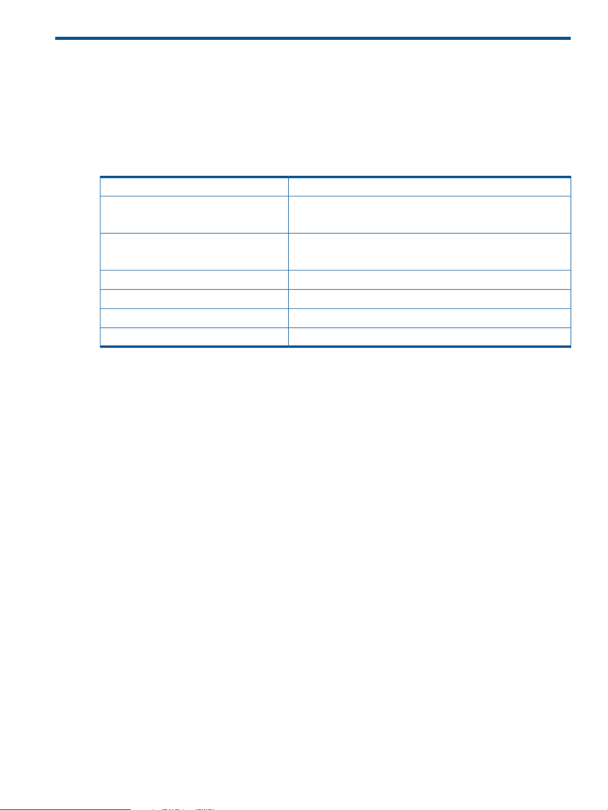
Locating the HP P4800 G2 solution warranty entitlement labels
You must locate and identify the serial number on the HP P4800 G2 solution components to obtain
service under the warranty. A warranty entitlement label (see Figure 6 (page 14)) is placed in each
of the following locations on the HP P4800 G2 solution:
• Top of the disk enclosure drawer. To access the label, pull out a disk enclosure drawer and
look at the top of the drawer near the front.
• Right side of the server blade. To access the label, pull out the affected server blade and look
on the right side of the blade.
Troubleshooting 13
Page 14
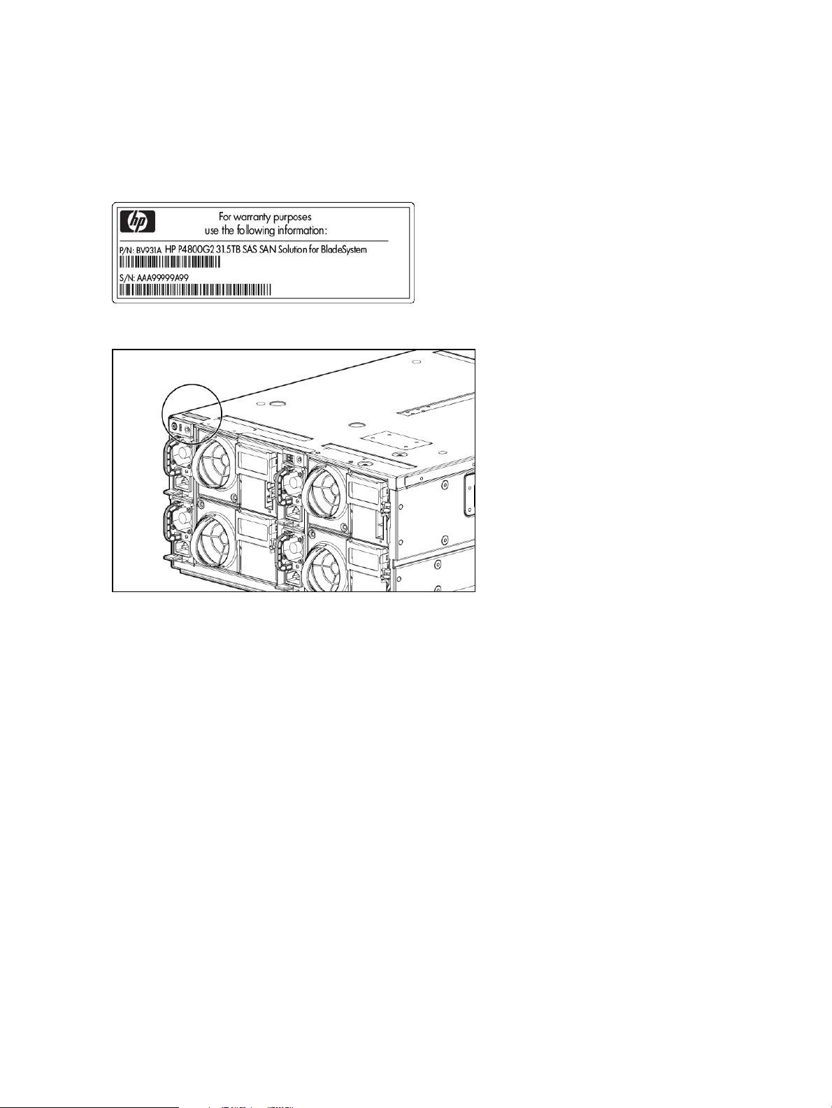
• Top of the SAS switch, near the back. To access the label, pull the affected SAS switch out of
the blade enclosure and look at the top of the SAS switch.
• Back of the disk enclosure chassis, left-hand front, top corner of the chassis.
The back of the disk enclosure chassis may be the most accessible label, as shown in Figure 7
(page 14).
Figure 6 Warranty entitlement label
Figure 7 Warranty entitlement label location
Performing field system recovery of the HP P4800 G2 solution
Overview
The field system recovery procedures for the HP P4800 G2 solution includes the following tasks:
• Obtaining the feature registration license key for the HP P4800 G2 solution.
• Running server diagnostics
• Re-imaging the HP P4460sb G2 server blade or the HP P4000sb server blade with the SAN/iQ
software and re-installing the license key.
Before you start
Have the following items ready:
• BIOS version I27, 09/30/2010 installed on the HP P4800 G2 solution
• USB flash drive, formatted with a Windows FAT 32 file system (this is the default for Windows
XP)
• HP P4000 Storage System Quick Restore .iso or CD created from the .iso
• HP SmartStart CD x64
• HP P4000 Management Software DVD
14 Maintaining the HP P4800 G2 solution
Page 15

Obtaining a license key
You must obtain a license key for the server blade before you begin the SAN/iQ software imaging
process. First, you obtain the MAC address of the HP P4800 G2 solution, then request the license
key using the MAC address.
Obtain the MAC address
Complete the following steps:
1. Log into iLO for the server blade.
2. Navigate to the System Information →NIC tab to obtain the eth0/Port 1 MAC address.
3. Copy the MAC address for future use.
Request the license key
The easiest way to enter the license key into the HP P4800 G2 solution is by using a USB flash
drive. You may also enter in the license key if you do not have a USB flash drive.
1. Go to the HP Software Licensing portal at https://webware.hp.com and click Manage licenses.
2. Follow the steps to reprint the original license key.
3. Prepare the key for use in the system recovery process.
Name the file as follows, with no file extension:
featurekey_<MAC address with no colons>
For example:
featurekey_0030482A189B
4. Save this file to the USB flash drive.
5. If you have more than one server blade to image, repeat steps in both sections “Obtain the
MAC address” (page 15) and “Obtaining a license key” (page 15).
6. Re-image the SAN/iQ software.
Re-imaging the server blade with the SAN/iQ software
If you do not have the license key, start with the instructions, “Obtaining a license key” (page 15),
for obtaining the MAC address and license key.
To re-image the server blades, perform the steps in the following sections for each blade.
Verify minimum server requirements
1. Log in to the iLO for the server blade.
2. Mount the HP SmartStart CD x64 using Virtual Mount.
3. Boot the server blade from the CD.
4. Select a language.
5. Accept the HP End User License Agreement.
6. Select Maintenance.
7. Select HP Insight Diagnostics.
8. On the Survey tab, verify that the specified items in the Overview category (default) meet the
minimum requirements listed in Table 2 (page 16).
CAUTION: If any items do not meet the requirements listed in Table 2 (page 16) and Table 3
(page 16), do not continue with this procedure.
Performing field system recovery of the HP P4800 G2 solution 15
Page 16

Table 2 Minimum requirements, overview category
Minimum requirementItem
CPU
NIC
CPU on the server blade: Intel Xeon Processor @ 2.40
Ghz
37 hard drives, which include the following:Type and number of drives
• Slot 2: 35 drives on the HP Smart Array P700m
controller
• Slot 0: 2 drives on the HP Smart Array P410i
controller
24 GBMemory
For the HP P4460sb G2 server blade, the Network
Controller is Emulex OneConnect 10Gb NIC:
v2.102.453.0 or later.
The HP P4000sb server blade has a Broadcom Network
Controller with no minimum requirement.
9. From the Categories list, select Storage.
10. Verify that the specified item meets the minimum requirements listed in Table 3 (page 16).
Table 3 Minimum requirements, storage category
Minimum requirementItem
Array Controller in Slot 0: HP Smart Array P410i
controller
• Model: HP P410i
• Firmware: 3.52 or later
• Installed Memory: 0 MB
• BIOS boot device order: 1
Array Controller in Slot 2: HP Smart Array P700m
controller
Run server diagnostics
1. On the HP Insight Diagnostics Test tab, select Quick Test and specify the number of loops.
2. Click Begin Testing.
The Survey Tab displays the data from the tests.
Wait for the tests to finish, which may take several minutes.
3. When the tests have completed, select the Log tab and check the failure log to see if the Quick
Test reports any failures.
4. If the Quick Test reports any errors, fix all errors before continuing.
If you need more information about an error, run a Complete Test on any component that
reported a failure.
If you want to run only specific tests, use the Custom Test option.
For assistance with the Complete or Custom Test options, see the HP SmartStart CD x64 or
contact HP technical support.
• Model: HP P700m
• Firmware: 7.22 or later
• Installed Memory: 512 MB
• Battery1: OK
• BIOS boot device order: 2
5. Click Exit Diagnostics.
6. Disconnect the HP SmartStart CD x64 from Virtual Media and reboot.
16 Maintaining the HP P4800 G2 solution
Page 17

7. Image the SAN/iQ software.
Image the SAN/iQ software
IMPORTANT: If the server blade accidentally power-cycles during the SAN/iQ software imaging
process, you cannot successfully resume or restart the imaging. You must begin with “Re-imaging
the server blade with the SAN/iQ software” (page 15).
1. Log in to the iLO for the server blades.
2. Mount the HP P4000 Storage System Quick Restore .iso using Virtual Mount.
3. When prompted, insert the USB flash drive containing the license key file.
NOTE: Use the iLO Dongle (delivered with the HP P4800 G2 solution) to convert the USB
flash drive into a USB port so that you can plug in the USB key.
4. When prompted to identify the OS version to install, enter Y.
IMPORTANT: Manually entering the license key
If the installer program cannot find a properly formatted license key on the USB flash drive,
you will be given the chance to enter in the license key.
Enter the license key if prompted. You have three attempts to correctly enter a valid HP license
key. If all three attempts are unsuccessful, restart the process with Step 1.
5. Finish the SAN/iQ software imaging.
Finish the SAN/iQ software imaging
The imaging process starts and displays the Auto Imaging Done message when complete.
1. Disconnect the Virtual Media using iLO.
2. Remove the USB flash drive from the Dongle.
3. Reboot the server blades.
4. Enter start to log into the server blade.
5. Navigate to Network TCP/IP Settings.
6. Assign an IP address to the server blade.
The server blade is now ready for use.
Next steps
Install the CMC from the HP P4000 Management Software DVD. Open the CMC, and use the
wizards on the Getting Started Launch Pad to begin using the HP P4800 G2 solution.
Repairing a storage system
For instructions on repairing a storage system, see the “Repairing a Storage System” and the
“Powering Off the Storage System” sections in the HP P4000 SAN Solution User Guide.
RAID 10 disk replacement and rebuild behavior
The RAID 10 configuration includes a single hot spare in bay 35.
When a disk is removed or fails in a RAID 10 configuration, the hot spare automatically begins
rebuilding. When the failed disk is replaced, the replacement disk begins rebuilding rather than
becoming the hot spare. At that time, the disk in bay 35 transitions back to being a hot spare. This
means that a simple disk replacement involves two rebuilds.
If more than one disk fails or is removed, the hot spare begins rebuilding one of the failed or
removed disks. When the multiple failed disks are replaced, the P700 controller attempts to restore
the disk in bay 35 as a hot spare, but it can only rebuild a single disk at a time. Any disks that
Repairing a storage system 17
Page 18

are queued for rebuilding will be reported as "OK" by the RAID controller (via the hpacucli). The
Disk Status tab in the CMC shows all disks as unsafe to remove, except the disk that is currently
rebuilding.
Upgrading SAN/iQ software
For instructions on upgrading the SAN/iQ software, see the P4000 SAN Solution Software Release
Notes.
Adding capacity to an existing P4800 G2 SAN
The P4800 G2 SAN can be expanded in 2-node increments, up to a total of eight server blades
and four disk enclosures. Adding additional nodes to an existing SAN requires field installation.
Because of the recommendation to power off the SAS switches and corresponding disk enclosures
if installing the new equipment into the same rack, the customer must first safely take the SAN
offline.
Before adding nodes to an existing SAN, upgrade to the latest SAN/iQ software. Otherwise, the
new nodes will operate at the older software version.
Customer requirements
Before beginning the equipment installation, the customer must perform the following actions:
• Disconnect iSCSI sessions from the SAN volumes and snapshots
• Use the Shut Down Management Group feature in the CMC
After the field installation, the customer can finish adding the configured storage to the existing
SAN as follows:
• Manually power on the server blades for the existing SAN and wait for the management
group to come up in the CMC
• Discover the new server blades in the CMC using the Find feature
• Add the newly discovered systems to the existing management group and cluster, or create
a new cluster if desired
If adding the new storage to the existing cluster, the volume and snapshot data restripes on
all the storage systems.
Upgrading firmware
Follow the procedures for upgrading the firmware of each component located in the individual
component product user guides. For more information, see the component guides listed in
“Additional component removal and replacement instructions” (page 20).
The following operations will take a volume offline:
• Upgrading the controller firmware
All controllers must run the same firmware version. (For instructions, see the component guides
listed in “Component removal and replacement instructions” (page 20).)
Since zero-downtime firmware flash is not supported for the controllers in the HP P4800 G2
solution, you must run the flash utility on both of the server blades. After running flash utility,
reboot both server blades so the update occurs.
• Upgrading the disk enclosure firmware
• Upgrading the disk enclosure drive firmware
IMPORTANT: Be sure to first power down the disk enclosures before upgrading the disk
enclosure drive firmware.
18 Maintaining the HP P4800 G2 solution
Page 19

• Upgrading the SAS switch firmware
• Upgrading the VC Flex-10 firmware
• Upgrading the server blade firmware
If a volume is not replicated, upgrades to the server blade firmware and OA firmware (BIOS) will
take the volume offline.
Upgrading firmware 19
Page 20

4 Removing and replacing the HP P4800 G2 solution
components
This section contains information and procedures specific to replacing the HP P4800 G2 solution
components.
Additional component removal and replacement instructions
For detailed information about the removal and replacement of HP P4800 G2 solution components,
see the resources listed in Table 4 (page 20). These documents are located on the HP P4800 G2
SAN Solution for BladeSystem documentation CD that accompanies the HP P4800 G2 solution.
Table 4 Component removal and replacement instructions
ResourceComponent
HP ProLiant BL460c G7 Server Blade Maintenance and Service GuideHP P4460sb G2 server blade
HP ProLiant BL460c G6 Server Blade Maintenance and Service GuideHP P4000sb server blade
HP 3Gb SAS BL Switch Replacement InstructionsHP SAS switch (pass-through modules)
HP Smart Array Controllers for HP ProLiant Servers User GuideHP Smart Array P700m controller
HP 600 Modular Disk System Maintenance and Service GuideHP disk enclosures
HP BladeSystem c7000 Enclosure Maintenance and Service GuideHP c-Class blade enclosure
HP Smart Array Controllers for HP ProLiant Servers User GuideHP Smart Array P410i controller (BIOS boot
controller)
Identifying hot pluggable and non-hot pluggable components
IMPORTANT: Hot add and hot removal of the disk enclosures are not supported by HP P4800
G2 SAS BladeSystem SAN Solution.
The following HP P4800 G2 solution components are hot-pluggable; therefore, you do not need
to power down the device before replacing a part:
• Drives
• External fans
• Power supplies
• Blade disk drives
All other HP P4800 G2 solution components are not hot-pluggable. You must first power down
the device before replacing a part.
CAUTION: To prevent losing access to data during any maintenance operation on components
of the SAS fabric, including the SAS switches, SAS cables, and I/O modules on the disk enclosure,
first power down the server blades using the procedures to shut down the management group in
the CMC Online Help or HP P4000 SAN Solution User Guide.
Replacing the server blade and server blade components
For more detailed instructions on replacing the server blade or server blade components, see
Table 4 (page 20) for resources.
20 Removing and replacing the HP P4800 G2 solution components
Page 21

Replacing a server blade
This section describes the implications for the HP P4800 G2 solution software and not the
mechanical aspects of replacing the server blade.
WARNING! Administrators should verify the firmware version of a replacement server blade
before inserting it in the blade enclosure.
WARNING! Be sure to only replace a server blade in the bay from which it was removed. Do
not swap or move server blades in a blade enclosure or disk enclosure in HP P4800 G2 solution
systems. If you do, nodes will lose failover ability and you may lose connectivity to the disks and
network.
WARNING! For cooling practices, do not leave a server bay open for an extended period of
time. When removing an active component, immediately replace it with a blank.
IMPORTANT: If the boot disk(s) from the blade being replaced are available, placing them in
the new blade allows it to boot to its original configuration. Do not reset the network settings if
you are using the original boot disk(s) on the blade being replaced.
IMPORTANT: If the original boot disk(s) are not available or are damaged, the blade must be
re-imaged using a recovery CD. Doing so requires that the administrator access the console of the
blade through the iLO (or blade KVM dongle) to set the server name and IP address. If you are
not using the original boot disk(s), be sure to reset the network settings.
IMPORTANT: The HP P4800 G2 solution should handle a single blade failure for an extended
period of time without loss of data or lost access to the data. The cluster, however, will remain in
a degraded state until the replacement blade is functioning.
To prepare the server blade for replacement:
1. Confirm the RAID and customer data.
Ensure that RAID is configured on the old blade and that the customer data exists on the disk
enclosures.
2. Confirm the IP address.
Ensure that the existing server blade is configured with a static or reserved IP address and not
DHCP. If necessary, convert the server blade to a static or reserved IP address. Record this IP
address for verification after the process is complete.
3. Record the MAC address.
Record the MAC address of the old blade for later use. Also record the server blade hostname
for later verification.
4. Delete the NIC bond.
Delete any NIC bond previously established on the old blade by using the console or the
CMC. The NIC bond must be deleted because it retains the MAC address of the old blade.
If you are unable to delete the NIC bond at this time, make sure to delete it on the power
cycle following the blade swap.
To replace the server blade or its system board:
1. Power down the server blade.
To power down the server blade from the CMC, see the “Powering off the storage system”
instructions in the HP P4000 SAN Solution User Guide.
2. Note the server blade bay number, and then remove the server blade from the blade enclosure.
NOTE: For instructions on removing and replacing server blade components, see Table 4
(page 20) for the applicable server blade maintenance and service guide.
Replacing the server blade and server blade components 21
Page 22

3. Ensure that all components of the original blade are in place in the replacement blade. In
particular, ensure that:
• The original system disks are in place. This task is essential.
• The memory size of the replacement blade is a minimum of 24 GB or larger.
• The HP Smart Array P700m controller card is in place.
4. Insert the blade in its original bay in the blade chassis.
5. Connect to the iLO, create a user, and assign the password (make sure the password is the
same password that is assigned to the other blades). The IP address is configured automatically
to be the same IP address as the original blade.
For more information, see “HP P4800 G2 solution cabling” (page 31).
6. Boot the server blade.
7. Verify that the server blade can access the disk storage by using the CMC.
Replacing a server blade disk drive
The system disk on a server blade comprises a logical RAID 0 disk that is mirrored over two physical
SFF disk drives in the server blade. As long as one drive continues to operate, the server blade
can operate.
You do not need to power down the server blade; instead, you can hot-swap disk drives. However,
you must replace the removed drive with a drive of the same size or larger.
To replace a disk drive in the server blade:
1. Check the state of the internal logical disk drive.
For more information, see Table 1 (page 13) for the applicable server blade user guide.
2. If the state is failed, follow the procedure in “Replacing both server blade disk drives”
(page 22).
3. Remove the failed drive.
If you remove the wrong drive, the mirror set will break, and the server blade may crash.
Reinsert the good drive and reboot the server blade.
For instructions on removing the drive, see Table 4 (page 20) for the applicable server blade
maintenance and service guide.
4. Insert the replacement drive.
Replacing both server blade disk drives
As long as one disk drive in the server blade continues to operate, the server blade can operate.
However if both disk drives fail, the system disk is lost and you must restore the server blade.
To reinstall a server blade:
1. Remove both disk drives.
2. Insert two replacement drives.
3. Reinstall the server blade by following the quick restore instructions, see “Performing field
system recovery of the HP P4800 G2 solution” (page 14).
Replacing the controller and controller components
This section describes how to replace the controller and its components (see Figure 8 (page 23)).
22 Removing and replacing the HP P4800 G2 solution components
Page 23

Figure 8 HP Smart Array P700m controller
1. Status LEDs (runtime LEDs)
2. Connector
3. Cache
4. Connector for the cable to the cache
5. Mezzanine connector to system board
Replacing the controller
The following steps refer to “HP Smart Array P700m controller” (page 23).
1. Verify component failure by checking LED and error messages.
To interpret the illumination pattern of these LEDs, see “Runtime LEDs for P700m model” in the
HP Smart Array Controllers for HP ProLiant Servers User Guide.
2. Back up all data.
3. Close all applications.
4. Power down the server blade using the CMC.
Wait at least 1 minute for the blade to power down. This procedure flushes all data from the
cache.
To power down the server blade from the CMC, see the “Powering off the storage system”
instructions in the HP P4000 SAN Solution User Guide.
CAUTION: Since the HP P4800 G2 solution uses external data storage, make sure that the
server blade is the first unit to be powered down and the last to be powered up. This precaution
ensures that the system does not mark the drives as failed when the server blade is powered
up.
5. Remove the server blade from the blade enclosure.
6. Remove the access panel from the server blade.
7. Remove the cache, keeping it connected to the battery.
NOTE: When removing the cache to transfer data, the battery must remain connected so
that the data is preserved.
8. Remove the existing controller.
9. Install the replacement controller.
Replacing the controller and controller components 23
Page 24

10. Plug the cache into the connector on the controller, routing the battery cable so that the cache
and battery can be removed together if necessary.
NOTE: Keep the battery connected to the cache so that the data is preserved.
11. Reinstall the access panel.
12. Reinstall the server blade in the blade enclosure.
After reinstalling the server blade, reset the BIOS. For instructions, see “CMC does not detect
drives” (page 13).
13. Verify component status.
14. Confirm that both server blades are running the same firmware version.
NOTE: Use the CMC Hardware Report to view the controller firmware version.
If the server blades are not running the same firmware version, update the controller firmware
with the Smart Update Firmware DVD located at hp.com/support and drivers.
For detailed instructions, see “Installing a mezzanine controller in a previously configured server
blade” in the HP Smart Array Controllers for HP ProLiant Servers User Guide.
For instructions on replacing the battery and cache, see “Upgrading or replacing controller options”
in the HP Smart Array Controllers for HP ProLiant Servers User Guide.
Replacing the VC Flex-10 module
CAUTION: Be sure to update the firmware on the new VC Flex-10 module. This operation will
take the volumes offline.
IMPORTANT: Clients will lose connectivity during this procedure unless using a bonded network.
If not using a bonded network, clients should be disconnected before starting the procedure. In
addition, both externally facing uplinks must be connected to your external network. If uplinks are
not connected to the external network, connectivity will be lost when one of the Flex-10 switches
goes offline during a firmware update.
To replace a VC Flex-10 module:
1. Disconnect the network connections into the VC Flex-10 module (bay 1 or 2).
2. Remove the VC Flex-10 module.
3. Replace the VC Flex-10 module.
4. Reconnect the cables that were disconnected in Step 1 to their original ports.
5. Restore the configuration settings.
For more information, see “Backing up HP P4800 G2 solution configurations” (page 11).
Replacing the SAS switch
This section provides instructions for removing and replacing the SAS switch in the HP P4800 G2
solution.
CAUTION: Before replacing the SAS switch, be sure to power down the server blades using the
procedures to shut down the management group in the CMC Online Help or HP P4000 SAN
Solution User Guide.
24 Removing and replacing the HP P4800 G2 solution components
Page 25

IMPORTANT: Replace the SAS switches one at a time. When you remove a switch, I/O continues
on the remaining switch. Before resetting a switch, verify that all storage is accessible by the
remaining data path. Replacing both SAS switches at one time disconnects the storage and could
compromise data integrity.
If a SAS switch fails, storage access continues through the remaining SAS switch. This causes
storage access to set a preference to all LUNs in the remaining data path. This preference remains
in place until the controllers in the blade enclosure are power cycled, or the remaining path becomes
unavailable.
CAUTION: Power down the disk enclosure before disconnecting a SAS cable. Failing to do so
may damage the I/O module.
To replace the SAS switch:
1. Remove the power cable.
2. Disconnect the SAS cables, noting which cable goes to which port.
3. Remove the switch.
4. Install the replacement switch.
5. Attach the power cable.
6. Update the switch firmware.
a. Open the HP Virtual SAS Manager.
b. Select Force VSM Active.
This selection copies the zone and firmware information from the active switch to the passive,
replacement switch. The replacement switch then becomes the active switch.
7. Reconnect the SAS cables to their original locations, see “HP P4800 G2 solution cabling”
(page 31).
NOTE: Do not attach the SAS cables to the replacement switch until the firmware update is
complete.
Wait at least 60 seconds before removing another SAS switch.
The SAS switch should now provide a redundant access path to storage. Storage controllers will
distribute I/O evenly over the switches upon restart.
Replacing a SAS cable
CAUTION: Failing to follow these steps in this order may damage the I/O module.
1. Before disconnecting a SAS cable, power down the server blades using the procedures to
shut down the management group in the CMC Online Help or HP P4000 SAN Solution User
Guide.
2. Manually power off the disk enclosure.
3. Replace the SAS cable.
See “HP P4800 G2 solution cabling” (page 31) for an illustration of HP P4800 G2 solution
connectivity.
Replacing a SAS cable 25
Page 26

Replacing the disk enclosure I/O module
This section describes how to remove and replace the disk enclosure I/O module on the HP P4800
G2 solution.
CAUTION: Before replacing the I/O module, be sure to power down the server blades using the
procedures to shut down the management group in the CMC Online Help or HP P4000 SAN
Solution User Guide. In addition, be sure the hard drive drawer is closed completely before
removing or replacing the disk enclosure I/O module.
CAUTION: Power down the disk enclosure before disconnecting a SAS cable.
To remove the component:
1. Disconnect the SAS cables, and release the I/O handle.
2. Push the I/O handle down to unlatch the I/O module.
3. Remove the I/O module.
Figure 9 Removal of the I/O module
CAUTION: For best cooling practices, do not operate the enclosure for extended periods with
more than one component or blank removed. When removing an active component, replace it
with a blank.
To replace the I/O module, reverse the removal procedure.
Replacing the disk enclosure power supply
There are four power supplies in each disk enclosure chassis—two on the left and two on the right.
The system can operate with a single power supply on the left and a single power supply on the
right.
1. Remove a power cable.
2. Remove the power supply unit.
3. Insert a new power supply unit.
4. Reattach the power cable.
Replacing the disk enclosure fan
There are four fans in each disk enclosure chassis. The system can operate for a short period with
one fan removed.
NOTE: The disk enclosure drawer must be closed while you replace the fan module.
26 Removing and replacing the HP P4800 G2 solution components
Page 27

1. Remove fan unit.
2. Insert the new fan unit.
Replacing the disk enclosure hard drive
CAUTION: Before replacing the disk enclosure hard drive, be sure to power down the server
blades using the procedures to shut down the management group in the CMC Online Help or HP
P4000 SAN Solution User Guide.
IMPORTANT: Before pulling a drive out of the disk enclosure, HP recommends that you use the
CMC to turn on the drive LED so that you can physically identify the correct drive to replace.
For detailed instructions on how to physically remove and replace a hard drive, see the “Removal
and replacement procedures” chapter in the HP 600 Modular Disk System Maintenance and
Service Guide.
For general instructions on replacing disk drives and ensuring data availability, see the HP P4000
SAN Solution User Guide.
Replacing the disk enclosure hard drive 27
Page 28

5 Support and other resources
Contacting HP
For worldwide technical support information, see the HP support website:
http://www.hp.com/support
Before contacting HP, collect the following information:
• Product model names and numbers
• Technical support registration number (if applicable)
• Product serial numbers
• Error messages
• Operating system type and revision level
• Detailed questions
Subscription service
HP recommends that you register your product at the Subscriber's Choice for Business website:
http://www.hp.com/go/e-updates
After registering, you will receive e-mail notification of product enhancements, new driver versions,
firmware updates, and other product resources.
HP Insight Remote Support software
HP strongly recommends that you install HP Insight Remote Support software to complete the
installation or upgrade of your product and to enable enhanced delivery of your HP Warranty,
HP Care Pack Service or HP contractual support agreement. HP Insight Remote Support supplements
your monitoring, 24x7 to ensure maximum system availability by providing intelligent event
diagnosis, and automatic, secure submission of hardware event notifications to HP, which will
initiate a fast and accurate resolution, based on your product’s service level. Notifications may be
sent to your authorized HP Channel Partner for on-site service, if configured and available in your
country. The software is available in two variants:
• HP Insight Remote Support Standard: This software supports server and storage devices and
is optimized for environments with 1 to 50 servers. Ideal for customers who can benefit from
proactive notification, but do not need proactive service delivery and integration with a
management platform.
• HP Insight Remote Support Advanced: This software provides comprehensive remote monitoring
and proactive service support for nearly all HP servers, storage, network, and SAN
environments, plus selected non-HP servers that have a support obligation with HP. It is
integrated with HP Systems Insight Manager. A dedicated server is recommended to host both
HP Systems Insight Manager and HP Insight Remote Support Advanced.
Details for both versions are available at:
http://www.hp.com/go/insightremotesupport
To download the software, go to Software Depot:
http://www.software.hp.com
Select Insight Remote Support from the menu on the right.
28 Support and other resources
Page 29

Related information
The following documents provide related information:
• HP Converged Infrastructure Reference Architecture for VMware View
• HP BladeSystem c-Class Enclosure Troubleshooting Guide
• HP BladeSystem c7000 Enclosure Maintenance and Service Guide
This document should only be used by persons qualified to service computer equipment.
• HP BladeSystem c7000 Enclosure Quick Setup Instructions
• HP BladeSystem Onboard Administrator User Guide
• HP Integrated Lights-Out 2 User Guide
• Virtual Connect for c-Class BladeSystem User Guide
• HP P4000 SAN Solution User Guide
• HP ProLiant BL460c G7 Server Blade Maintenance and Service Guide
• HP ProLiant BL460c G7 Server Blade Installation Instructions
• HP ProLiant BL460c G7 Server Blade User Guide
• HP ProLiant BL460c G6 Server Blade Maintenance and Service Guide
• HP ProLiant BL460c G6 Server Blade Installation Instructions
• HP ProLiant BL460c G6 Server Blade User Guide
• HP 3Gb SAS BL Switch replacement instructions
• HP 3Gb SAS BL Switch installation instructions
• HP 3Gb SAS BL Switch user guide
• HP Smart Array Controllers for HP ProLiant Servers User Guide
• HP Virtual SAS Manager User Guide
• HP Direct-Connect External SAS storage for HP BladeSystem Solutions Deployment Guide
• HP ProLiant Servers Troubleshooting Guide
• HP 600 Modular Disk System User Guide
• HP 600 Modular Disk System Maintenance and Service Guide
This document describes removal and replacement procedures for the disk enclosure (also
known as the HP 600 Modular Disk System). It should only be used by persons qualified to
service computer equipment.
You can find these documents on the Manuals page of the HP Business Support Center website:
http://www.hp.com/support/manuals
To locate a HP P4800 G2 solution document, see “Documentation available” (page 9).
HP websites
For additional information, see the following HP websites:
• http://www.hp.com
• http://www.hp.com/go/storage
• http://www.hp.com/service_locator
• http://www.hp.com/support/manuals
• http://www.hp.com/support/downloads
Related information 29
Page 30

Rack stability
Rack stability protects personnel and equipment.
WARNING! To reduce the risk of personal injury or damage to equipment:
• Extend leveling jacks to the floor.
• Ensure that the full weight of the rack rests on the leveling jacks.
• Install stabilizing feet on the rack.
• In multiple-rack installations, fasten racks together securely.
• Extend only one rack component at a time. Racks can become unstable if more than one
component is extended.
Customer self repair
HP customer self repair (CSR) programs allow you to repair your HP product. If a CSR part needs
replacing, HP ships the part directly to you so that you can install it at your convenience. Some
parts do not qualify for CSR. Your HP-authorized service provider will determine whether a repair
can be accomplished by CSR.
For more information about CSR, contact your local service provider, or see the CSR website:
http://www.hp.com/go/selfrepair
Replaceable parts
This product contains replaceable parts. To identify the replaceable parts, see the individual
component guides listed in “Component removal and replacement instructions” (page 20).
Parts that are available for customer self repair (CSR) are indicated as follows:
✓ Mandatory CSR. You order the part directly from HP and repair the product yourself. On-site or
return-to-depot repair is not provided under warranty.
• Optional CSR. You can order the part directly from HP and repair the product yourself, or you
can request that HP repair the product. If you request repair from HP, you may be charged for the
repair depending on the product warranty.
-- No CSR. The replaceable part is not available for self repair. For assistance, contact an
HP-authorized service provider.
For more information about CSR, contact your local service provider. For North America, see the
CSR website:
http://www.hp.com/go/selfrepair
To determine the warranty service provided for this product, see the warranty information website:
http://www.hp.com/go/storagewarranty
To order a replacement part, contact an HP-authorized service provider or see the HP Parts Store
online:
http://www.hp.com/buy/parts
30 Support and other resources
Page 31

A HP P4800 G2 solution cabling
The HP P4800 G2 solution SAS cabling is shown in Figure 10 (page 31) through Figure 13
(page 34).
Figure 10 HP P4800 G2 solution 2-node cabling
1. HP VC Flex-10 modules (2)
2. HP 3Gb SAS BL switches (2)
3. HP ProLiant Onboard Administrator
4. Disk enclosure power on button
31
Page 32

Figure 11 HP P4800 G2 solution 4-node cabling
1. HP VC Flex-10 modules (2)
2. HP 3Gb SAS BL switches (2)
3. HP ProLiant Onboard Administrator
4. Disk enclosure power on buttons (2)
32 HP P4800 G2 solution cabling
Page 33

Figure 12 HP P4800 G2 solution 6-node cabling
1. HP VC Flex-10 modules (2)
2. HP 3Gb SAS BL switches (2)
3. HP ProLiant Onboard Administrator
4. Disk enclosure power on buttons (3)
33
Page 34

Figure 13 HP P4800 G2 solution 8-node cabling
1. HP VC Flex-10 modules (2)
2. HP 3Gb SAS BL switches (2)
3. HP ProLiant Onboard Administrator
4. Disk enclosure power on buttons (4)
34 HP P4800 G2 solution cabling
Page 35

B Regulatory compliance notices
This section contains regulatory notices for the HP P4800 G2 SAN Solution for BladeSystem.
Regulatory compliance identification numbers
For the purpose of regulatory compliance certifications and identification, this product has been
assigned a unique regulatory model number. The regulatory model number can be found on the
product nameplate label, along with all required approval markings and information. When
requesting compliance information for this product, always refer to this regulatory model number.
The regulatory model number is not the marketing name or model number of the product.
Product specific information:
HP P4000sb server blade
HP 4460sb G2 server blade
Regulatory model number: HSTNS-BC38-S
FCC and CISPR classification: Class A, 22:2005
These products contain laser components. See Class 1 laser statement in the “Laser compliance
notices” (page 39) section.
Federal Communications Commission notice
Part 15 of the Federal Communications Commission (FCC) Rules and Regulations has established
Radio Frequency (RF) emission limits to provide an interference-free radio frequency spectrum.
Many electronic devices, including computers, generate RF energy incidental to their intended
function and are, therefore, covered by these rules. These rules place computers and related
peripheral devices into two classes, A and B, depending upon their intended installation. Class A
devices are those that may reasonably be expected to be installed in a business or commercial
environment. Class B devices are those that may reasonably be expected to be installed in a
residential environment (for example, personal computers). The FCC requires devices in both classes
to bear a label indicating the interference potential of the device as well as additional operating
instructions for the user.
FCC rating label
The FCC rating label on the device shows the classification (A or B) of the equipment. Class B
devices have an FCC logo or ID on the label. Class A devices do not have an FCC logo or ID on
the label. After you determine the class of the device, refer to the corresponding statement.
Class A equipment
This equipment has been tested and found to comply with the limits for a Class A digital device,
pursuant to Part 15 of the FCC rules. These limits are designed to provide reasonable protection
against harmful interference when the equipment is operated in a commercial environment. This
equipment generates, uses, and can radiate radio frequency energy and, if not installed and used
in accordance with the instructions, may cause harmful interference to radio communications.
Operation of this equipment in a residential area is likely to cause harmful interference, in which
case the user will be required to correct the interference at personal expense.
Class B equipment
This equipment has been tested and found to comply with the limits for a Class B digital device,
pursuant to Part 15 of the FCC Rules. These limits are designed to provide reasonable protection
against harmful interference in a residential installation. This equipment generates, uses, and can
radiate radio frequency energy and, if not installed and used in accordance with the instructions,
may cause harmful interference to radio communications. However, there is no guarantee that
interference will not occur in a particular installation. If this equipment does cause harmful
interference to radio or television reception, which can be determined by turning the equipment
Regulatory compliance identification numbers 35
Page 36

off and on, the user is encouraged to try to correct the interference by one or more of the following
measures:
• Reorient or relocate the receiving antenna.
• Increase the separation between the equipment and receiver.
• Connect the equipment into an outlet on a circuit that is different from that to which the receiver
is connected.
• Consult the dealer or an experienced radio or television technician for help.
Declaration of Conformity for products marked with the FCC logo, United States only
This device complies with Part 15 of the FCC Rules. Operation is subject to the following two
conditions: (1) this device may not cause harmful interference, and (2) this device must accept any
interference received, including interference that may cause undesired operation.
For questions regarding this FCC declaration, contact us by mail or telephone:
• Hewlett-Packard Company P.O. Box 692000, Mail Stop 510101 Houston, Texas 77269-2000
• Or call 1-281-514-3333
Modification
The FCC requires the user to be notified that any changes or modifications made to this device
that are not expressly approved by Hewlett-Packard Company may void the user's authority to
operate the equipment.
Cables
When provided, connections to this device must be made with shielded cables with metallic RFI/EMI
connector hoods in order to maintain compliance with FCC Rules and Regulations.
Canadian notice (Avis Canadien)
Class A equipment
This Class A digital apparatus meets all requirements of the Canadian Interference-Causing
Equipment Regulations.
Cet appareil numérique de la class A respecte toutes les exigences du Règlement sur le matériel
brouilleur du Canada.
Class B equipment
This Class B digital apparatus meets all requirements of the Canadian Interference-Causing
Equipment Regulations.
Cet appareil numérique de la class B respecte toutes les exigences du Règlement sur le matériel
brouilleur du Canada.
European Union notice
This product complies with the following EU directives:
• Low Voltage Directive 2006/95/EC
• EMC Directive 2004/108/EC
Compliance with these directives implies conformity to applicable harmonized European standards
(European Norms) which are listed on the EU Declaration of Conformity issued by Hewlett-Packard
for this product or product family.
36 Regulatory compliance notices
Page 37

This compliance is indicated by the following conformity marking placed on the product:
Certificates can be obtained from http://www.hp.com/go/certificates.
Hewlett-Packard GmbH, HQ-TRE, Herrenberger Strasse 140, 71034 Boeblingen, Germany
Japanese notices
Japanese VCCI-A notice
Japanese VCCI-B notice
This marking is valid for non-Telecom products and EU
harmonized Telecom products (e.g., Bluetooth).
Japanese VCCI marking
Japanese power cord statement
Korean notices
Class A equipment
Japanese notices 37
Page 38

Class B equipment
Taiwanese notices
BSMI Class A notice
Taiwan battery recycle statement
Turkish recycling notice
Türkiye Cumhuriyeti: EEE Yönetmeliğine Uygundur
38 Regulatory compliance notices
Page 39

Laser compliance notices
English laser notice
This device may contain a laser that is classified as a Class 1 Laser Product in accordance with
U.S. FDA regulations and the IEC 60825-1. The product does not emit hazardous laser radiation.
WARNING! Use of controls or adjustments or performance of procedures other than those
specified herein or in the laser product's installation guide may result in hazardous radiation
exposure. To reduce the risk of exposure to hazardous radiation:
• Do not try to open the module enclosure. There are no user-serviceable components inside.
• Do not operate controls, make adjustments, or perform procedures to the laser device other
than those specified herein.
• Allow only HP Authorized Service technicians to repair the unit.
The Center for Devices and Radiological Health (CDRH) of the U.S. Food and Drug Administration
implemented regulations for laser products on August 2, 1976. These regulations apply to laser
products manufactured from August 1, 1976. Compliance is mandatory for products marketed in
the United States.
Dutch laser notice
French laser notice
Laser compliance notices 39
Page 40

German laser notice
Italian laser notice
Japanese laser notice
40 Regulatory compliance notices
Page 41

Spanish laser notice
Recycling notices
English recycling notice
Disposal of waste equipment by users in private household in the European Union
This symbol means do not dispose of your product with your other household waste. Instead, you should
protect human health and the environment by handing over your waste equipment to a designated
collection point for the recycling of waste electrical and electronic equipment. For more information,
please contact your household waste disposal service
Recycling notices 41
Page 42

Bulgarian recycling notice
Изхвърляне на отпадъчно оборудване от потребители в частни домакинства в Европейския
съюз
Този символ върху продукта или опаковката му показва, че продуктът не трябва да се изхвърля заедно
с другите битови отпадъци. Вместо това, трябва да предпазите човешкото здраве и околната среда,
като предадете отпадъчното оборудване в предназначен за събирането му пункт за рециклиране на
неизползваемо електрическо и електронно борудване. За допълнителна информация се свържете с
фирмата по чистота, чиито услуги използвате.
Czech recycling notice
Likvidace zařízení v domácnostech v Evropské unii
Tento symbol znamená, že nesmíte tento produkt likvidovat spolu s jiným domovním odpadem. Místo
toho byste měli chránit lidské zdraví a životní prostředí tím, že jej předáte na k tomu určené sběrné
pracoviště, kde se zabývají recyklací elektrického a elektronického vybavení. Pro více informací kontaktujte
společnost zabývající se sběrem a svozem domovního odpadu.
Danish recycling notice
Bortskaffelse af brugt udstyr hos brugere i private hjem i EU
Dette symbol betyder, at produktet ikke må bortskaffes sammen med andet husholdningsaffald. Du skal
i stedet den menneskelige sundhed og miljøet ved at afl evere dit brugte udstyr på et dertil beregnet
indsamlingssted for af brugt, elektrisk og elektronisk udstyr. Kontakt nærmeste renovationsafdeling for
yderligere oplysninger.
Dutch recycling notice
Inzameling van afgedankte apparatuur van particuliere huishoudens in de Europese Unie
Dit symbool betekent dat het product niet mag worden gedeponeerd bij het overige huishoudelijke afval.
Bescherm de gezondheid en het milieu door afgedankte apparatuur in te leveren bij een hiervoor bestemd
inzamelpunt voor recycling van afgedankte elektrische en elektronische apparatuur. Neem voor meer
informatie contact op met uw gemeentereinigingsdienst.
42 Regulatory compliance notices
Page 43

Estonian recycling notice
Äravisatavate seadmete likvideerimine Euroopa Liidu eramajapidamistes
See märk näitab, et seadet ei tohi visata olmeprügi hulka. Inimeste tervise ja keskkonna säästmise nimel
tuleb äravisatav toode tuua elektriliste ja elektrooniliste seadmete käitlemisega egelevasse kogumispunkti.
Küsimuste korral pöörduge kohaliku prügikäitlusettevõtte poole.
Finnish recycling notice
Kotitalousjätteiden hävittäminen Euroopan unionin alueella
Tämä symboli merkitsee, että laitetta ei saa hävittää muiden kotitalousjätteiden mukana. Sen sijaan sinun
on suojattava ihmisten terveyttä ja ympäristöä toimittamalla käytöstä poistettu laite sähkö- tai
elektroniikkajätteen kierrätyspisteeseen. Lisätietoja saat jätehuoltoyhtiöltä.
French recycling notice
Mise au rebut d'équipement par les utilisateurs privés dans l'Union Européenne
Ce symbole indique que vous ne devez pas jeter votre produit avec les ordures ménagères. Il est de
votre responsabilité de protéger la santé et l'environnement et de vous débarrasser de votre équipement
en le remettant à une déchetterie effectuant le recyclage des équipements électriques et électroniques.
Pour de plus amples informations, prenez contact avec votre service d'élimination des ordures ménagères.
German recycling notice
Entsorgung von Altgeräten von Benutzern in privaten Haushalten in der EU
Dieses Symbol besagt, dass dieses Produkt nicht mit dem Haushaltsmüll entsorgt werden darf. Zum
Schutze der Gesundheit und der Umwelt sollten Sie stattdessen Ihre Altgeräte zur Entsorgung einer dafür
vorgesehenen Recyclingstelle für elektrische und elektronische Geräte übergeben. Weitere Informationen
erhalten Sie von Ihrem Entsorgungsunternehmen für Hausmüll.
Recycling notices 43
Page 44

Greek recycling notice
Απόρριψη άχρηοτου εξοπλισμού από ιδιώτες χρήστες στην Ευρωπαϊκή Ένωση
Αυτό το σύμβολο σημαίνει ότι δεν πρέπει να απορρίψετε το προϊόν με τα λοιπά οικιακά απορρίμματα.
Αντίθετα, πρέπει να προστατέψετε την ανθρώπινη υγεία και το περιβάλλον παραδίδοντας τον άχρηστο
εξοπλισμό σας σε εξουσιοδοτημένο σημείο συλλογής για την ανακύκλωση άχρηστου ηλεκτρικού και
ηλεκτρονικού εξοπλισμού. Για περισσότερες πληροφορίες, επικοινωνήστε με την υπηρεσία απόρριψης
απορριμμάτων της περιοχής σας.
Hungarian recycling notice
A hulladék anyagok megsemmisítése az Európai Unió háztartásaiban
Ez a szimbólum azt jelzi, hogy a készüléket nem szabad a háztartási hulladékkal együtt kidobni. Ehelyett
a leselejtezett berendezéseknek az elektromos vagy elektronikus hulladék átvételére kijelölt helyen történő
beszolgáltatásával megóvja az emberi egészséget és a környezetet.További információt a helyi
köztisztasági vállalattól kaphat.
Italian recycling notice
Smaltimento di apparecchiature usate da parte di utenti privati nell'Unione Europea
Questo simbolo avvisa di non smaltire il prodotto con i normali rifi uti domestici. Rispettare la salute
umana e l'ambiente conferendo l'apparecchiatura dismessa a un centro di raccolta designato per il
riciclo di apparecchiature elettroniche ed elettriche. Per ulteriori informazioni, rivolgersi al servizio per
lo smaltimento dei rifi uti domestici.
Latvian recycling notice
Europos Sąjungos namų ūkio vartotojų įrangos atliekų šalinimas
Šis simbolis nurodo, kad gaminio negalima išmesti kartu su kitomis buitinėmis atliekomis. Kad
apsaugotumėte žmonių sveikatą ir aplinką, pasenusią nenaudojamą įrangą turite nuvežti į elektrinių ir
elektroninių atliekų surinkimo punktą. Daugiau informacijos teiraukitės buitinių atliekų surinkimo tarnybos.
44 Regulatory compliance notices
Page 45

Lithuanian recycling notice
Nolietotu iekārtu iznīcināšanas noteikumi lietotājiem Eiropas Savienības privātajās mājsaimniecībās
Šis simbols norāda, ka ierīci nedrīkst utilizēt kopā ar citiem mājsaimniecības atkritumiem. Jums jārūpējas
par cilvēku veselības un vides aizsardzību, nododot lietoto aprīkojumu otrreizējai pārstrādei īpašā lietotu
elektrisko un elektronisko ierīču savākšanas punktā. Lai iegūtu plašāku informāciju, lūdzu, sazinieties ar
savu mājsaimniecības atkritumu likvidēšanas dienestu.
Polish recycling notice
Utylizacja zużytego sprzętu przez użytkowników w prywatnych gospodarstwach domowych w
krajach Unii Europejskiej
Ten symbol oznacza, że nie wolno wyrzucać produktu wraz z innymi domowymi odpadkami.
Obowiązkiem użytkownika jest ochrona zdrowa ludzkiego i środowiska przez przekazanie zużytego
sprzętu do wyznaczonego punktu zajmującego się recyklingiem odpadów powstałych ze sprzętu
elektrycznego i elektronicznego. Więcej informacji można uzyskać od lokalnej firmy zajmującej wywozem
nieczystości.
Portuguese recycling notice
Descarte de equipamentos usados por utilizadores domésticos na União Europeia
Este símbolo indica que não deve descartar o seu produto juntamente com os outros lixos domiciliares.
Ao invés disso, deve proteger a saúde humana e o meio ambiente levando o seu equipamento para
descarte em um ponto de recolha destinado à reciclagem de resíduos de equipamentos eléctricos e
electrónicos. Para obter mais informações, contacte o seu serviço de tratamento de resíduos domésticos.
Romanian recycling notice
Casarea echipamentului uzat de către utilizatorii casnici din Uniunea Europeană
Acest simbol înseamnă să nu se arunce produsul cu alte deşeuri menajere. În schimb, trebuie să protejaţi
sănătatea umană şi mediul predând echipamentul uzat la un punct de colectare desemnat pentru reciclarea
echipamentelor electrice şi electronice uzate. Pentru informaţii suplimentare, vă rugăm să contactaţi
serviciul de eliminare a deşeurilor menajere local.
Recycling notices 45
Page 46

Slovak recycling notice
Likvidácia vyradených zariadení používateľmi v domácnostiach v Európskej únii
Tento symbol znamená, že tento produkt sa nemá likvidovať s ostatným domovým odpadom. Namiesto
toho by ste mali chrániť ľudské zdravie a životné prostredie odovzdaním odpadového zariadenia na
zbernom mieste, ktoré je určené na recykláciu odpadových elektrických a elektronických zariadení.
Ďalšie informácie získate od spoločnosti zaoberajúcej sa likvidáciou domového odpadu.
Spanish recycling notice
Eliminación de los equipos que ya no se utilizan en entornos domésticos de la Unión Europea
Este símbolo indica que este producto no debe eliminarse con los residuos domésticos. En lugar de ello,
debe evitar causar daños a la salud de las personas y al medio ambiente llevando los equipos que no
utilice a un punto de recogida designado para el reciclaje de equipos eléctricos y electrónicos que ya
no se utilizan. Para obtener más información, póngase en contacto con el servicio de recogida de
residuos domésticos.
Swedish recycling notice
Hantering av elektroniskt avfall för hemanvändare inom EU
Den här symbolen innebär att du inte ska kasta din produkt i hushållsavfallet. Värna i stället om natur
och miljö genom att lämna in uttjänt utrustning på anvisad insamlingsplats. Allt elektriskt och elektroniskt
avfall går sedan vidare till återvinning. Kontakta ditt återvinningsföretag för mer information.
Battery replacement notices
Dutch battery notice
46 Regulatory compliance notices
Page 47

French battery notice
German battery notice
Battery replacement notices 47
Page 48

Italian battery notice
Japanese battery notice
48 Regulatory compliance notices
Page 49

Spanish battery notice
Battery replacement notices 49
Page 50

Glossary
Acronyms and Abbreviations
CMC Central Management Console
CSR Customer Self Repair
DHCP Dynamic Host Configuration Protocol
EBIPA Enclosure bay IP addressing
ESX VMware's enterprise-class virtualization platform
FBWC Flash-backed write cache
FCC Federal Communications Commission
FOM Failover Manager
iLO 2 HP Integrated Lights-Out 2
iSCSI Internet SCSI)
KVM Keyboard, video, mouse switch
LUN Logical unit number
NIC Network interface card
OA Onboard Administrator
POST Power-on self test
RBSU ROM-based setup utility
RF Radio frequency
SAN Storage Area Network
SAS Serial-Attached SCSI
SFF Small Form Factor
SSH Secure Shell
UPS Uninterruptible power supply
VIP Virtual IP address
50 Glossary
Page 51

Index
A
available documents, 9
B
backing up
configurations, 11
backup configuration, 12
battery replacement notices, 46
C
cabling
diagram, 31
HP P4800 G2 solution, 31
Canadian notice, 36
component
replacement instructions, 20
components
hardware, 5
hot-pluggable, 20
non-hot-pluggable, 20
configuration
back view, 5
backing up, 11, 12
factory settings, 11
front view, 5
configuration backup
methods, 12
secure copy tool, 12
contacting HP, 28
controller
replacing, 22
customer self repair, 30
parts list, 30
D
Declaration of Conformity, 36
disk drive
server blade, 22
disk enclosure
fan, 26
hard drive, 27
power supply, 26
disk enclosure fan
replacing, 26
disk enclosure hard drive
replacing, 27
disk enclosure I/O module
replacing, 26
disk enclosure power supply
replacing, 26
Disposal of waste equipment, European Union, 41
document
related information, 29
documentation
HP website, 29
documentation available, 9
E
European Union notice, 36
F
Federal Communications Commission notice, 35
firmware
upgrades, 18
firmware upgrade, 20
Flex-10 module
replacing, 24
Flex-10 module, replacing, 24
H
hard drive
disk enclosure, 27
help
obtaining, 28
HP
technical support, 28
I
I/O module
replacing, 26
Insight Remote Support software, 28
J
Japanese notices, 37
K
Korean notices, 37
L
laser compliance notices, 39
M
maintenance
HP P4800 G2 solution, 13
warranty entitlement labels, 13
mezzanine controller
battery, 23
replacing, 23
mezzanine controller, replacing, 23
O
offline
volumes, 18
overview
general description, 5
P
parts
replaceable, 30
51
Page 52

R
rack stability
warning, 30
recovery
HP P4800 G2 solution, 14
recycling notices, 41
regulatory compliance
Canadian notice, 36
European Union notice, 36
identification numbers, 35
Japanese notices, 37
Korean notices, 37
laser, 39
recycling notices, 41
Taiwanese notices, 38
related documentation, 29
remote support software, 28
replacing
both server blade disk drives, 22
controller, 22
server blade, 21
server blade disk drive, 22
replacing the disk enclosure fan, 26
replacing the disk enclosure hard drive, 27
replacing the disk enclosure i/O module, 26
replacing the disk enclosure power supply, 26
replacing the I/O module, 26
replacing the mezzanine controller, 23
replacing the SAS cable, 25
replacing the SAS switch, 24
replacing the VC Flex-10 module, 24
utility
system backup, 12
V
VC Flex-10 module
bays, 24
configuration backup, 11
replacing, 24
Virtual Connect Flex-10 module
backing up configuration, 11
Virtual Connect Manager
for configuration backup, 11
rebuilding SAS switch, 12
W
warning
rack stability, 30
warranty entitlement labels
locations, 13
websites
customer self repair, 30
HP , 29
HP Subscriber's Choice for Business, 28
product manuals, 29
S
SAS cable, 25
SAS switch, 12, 24
server blade
replacement, 21
server blade disk drive
replacement, 22
replacing both, 22
solution configuration, 5
storage system
repair, 17
Subscriber's Choice, HP, 28
support software, remote, 28
T
Taiwanese notices, 38
technical support
HP, 28
service locator website, 29
troubleshooting
BIOS reset, 13
components, 13
HP P4800 G2 solution, 13
specific issues, 13
U
upgrading firmware, 20
52 Index
 Loading...