

Page 1

hp traffic director
server appliances
getting started guide for the hp
e-commerce traffic director server
appliances sa8200/sa8220 and the
hp traffic director server appliances
sa7200/sa7220
Page 2

© Copyright 2001 Hewlett-Packard Company. All rights reserved.
Hewlett-Packard Com pany
3000 Hanover Street
Palo Alto, CA 94304-1185
Publication Number
5971-0898
March 2001
Disclaimer
The information contai ne d in this document is subject to change witho ut notic e .
HEWLETT-PACKARD COMPANY MAKES NO WARRANTY OF ANY
KIND WITH REGARD TO THIS MATERIAL, INCLUDING, BUT NOT
LIMITED TO, THE IMPLIED WARRANTIES OF MERCHANTABILITY
AND FITNESS FOR A PARTICULAR PURPOSE. Hewlett-Packard shall not
be liable for errors contained herein or for incid ental or consequent ial damages
in connection with the furnishing, performance, or use of this material.
Hewlett-Packard assumes no responsibility for the use or reliabili ty of its
software on equipment that is not fu r nished by Hewlett-Packard.
Warranty
A copy of the specific warranty terms applicable to your Hewlett-Packard
products and replacement parts can be obtained from http://www.hp.com/
serverappliances/support/.
*Other brands and names are the property of their respective owne rs.
Page 3

Getting Started
Before You Begin
This document will guide you through the installation and basic
configuration of your HP e-Commerce Traffic Director Server
Appliance SA8200/SA8220 and HP Traffic Director Server
Appliance SA7200/SA7220.
NOTE: For ease of
reading, all models are
referred to as the SA 8220
throughout this
document. Unless noted
otherwise, all SA8220
references refer to all
models
This document covers the following topics:
• Physical installa tion
• Configuration checklists
• Running Setup using the Boot Monitor
• Configuring DNS
• Using the Graphical User Interface (GUI)
• Helpful hints
• Where to go from here
• Support information
Page 4

HP Traffic Director Server Appliances Getting Started Guide
Parts Checklist
Ensure that the items listed below are included in the box with your
system:
• HP e-Commerce Traffic Director Server Appliance SA8200/
SA8220 or HP Traffic Director Server Appliance SA7200/
SA7220, as appropriate
• HP Traffic Director Server Appliances User Guide
• HP Traffic Director Server Appliances Getting Started Guide
(this document)
• HP Traffic Director Server Appliances Release Notes
• AC power cord
• Null-modem cable
• RJ-45 network cable
• Rack and rail mounting brackets with Phillips mounting screws
Contact HP Customer Support if any of the above items are missing
from your shipment.
Support
Website
Visit http://www.hp.com/serverappliances/support/
for late breaking information and for details regarding the current
software release.
2
Page 5
Physical Installation
If you have already mounted your system, or if yo ur system d oes not
require mounting, proceed to “Wiring Co nnectio ns” later in this
document.
You can physically install the SA8220 in either of two ways. Each
installation method requires a particular type of mounting brackets,
and are included in the SA8220's shipping container.
• In a standard 19” rack, cantilevered from the mounting brackets
• In a cabinet with side rail mounts
Physical Installation
Rack
Installation
CAUTION: Do not use
the enclosed small
mounting brackets for
rack installation . These
are used for side rail
installation.
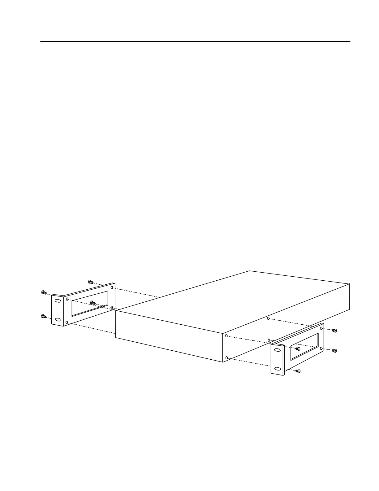
Rack mounting requires the use of the large mounting brackets, and
all eight of the included Phillips screws.
1. Locate the two large mounting brackets and the provided screws.
2. Attach a large mounting bracket t o each side of the SA822 0. Use
four screws to secure each bracket to the holes near the front of
the SA8220, as shown below.
NOTE: These screws are
provided with your rack
hardware, not the
SA8220.
Rack Mounting the SA8220
3. Position the SA8220 in the desired space of your 19” rack and
attach the front flange of each mounting bracket to the rack with
two screws each.
3
Page 6
HP Traffic Director Server Appliances Getting Started Guide
Side Rail
Installation
Side rail mounting of the SA8220 requires the use of the enclosed
small mounting brac kets and four of the Phillips head screws.
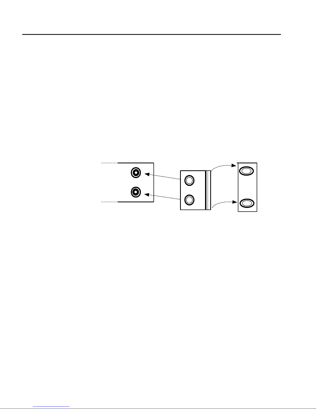
1. Locate the two small mounti ng bracket s and th e provided scre ws.
2. Attach a side rail to each SA8220 using the rows of five screw
holes on the side of the SA8220, equidistant from the top and
bottom, as shown below. The screws for this procedure are not
provided with the SA8220; they are supplied with your side rail
hardware.
SA8220 bracket
holes
side-view
Mounting bracket side-view
(connect to SA8220)
Rail mount holes
end-view
NOTE: The small
mounting brackets have
recesses that allow them
to fit over the front end of
the side rail.
Side Rail Mounting of the SA8220
3. Attach a small mounting bracket to each side of the SA8220,
using two of the provided screws for each bracket. Use the holes
nearest to the front of the SA8220.
4. Slide the SA8220 into the cabinet’s receiving rails and secure th e
front flange of each mounting bracket with two screws.
4
Page 7
Physical Installation
Wiring
Connections
1. On the rear of the SA8220, connect the provided AC power
cable.
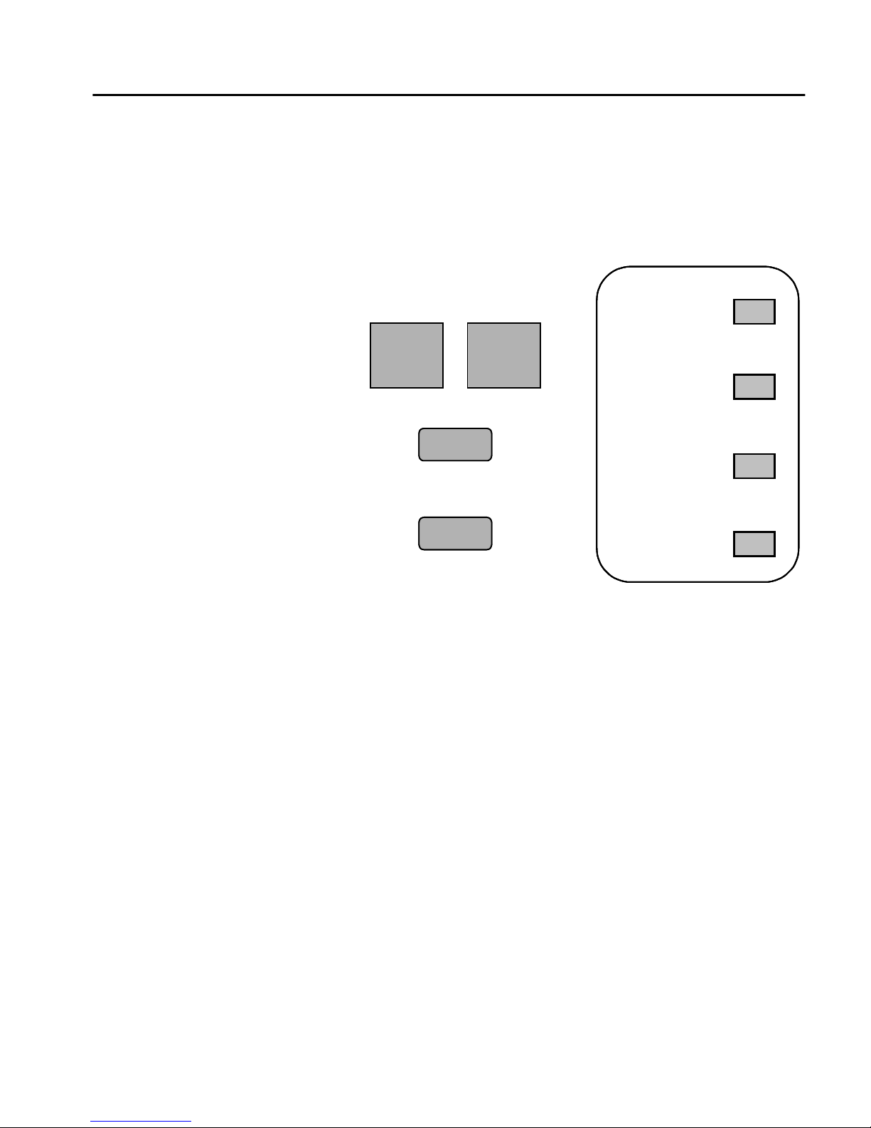
2. Refer to this diagram for all wiring connections on the front
panel of the SA8220.
Network Server
Network Server
Console
Console
Failover
Failover
Power
Power
Power
Status
Status
Status
Act 1
Act 1
Act 1
Act 2
Act 2
Act 2
NOTE: For more
information about serial
cable failover, see
Chapter 2 in the User
Guide.
Front Panel Ports and LEDs
3. For Single NIC (Network Interface Card) configurations:
Connect the Network port to your net work usi ng the provided RJ-
45 network cable.
For Dual NIC configurations: Connect the Network port to your
outside network, and the Server por t t o y our ser ver si de net wor k,
using the provided RJ-45 networ k cable and a network cable you
provide, respectively.
4. Use the provided serial cable to connect the Console serial port to
the serial port of any terminal or workstation capable of running
a terminal emulator program.
5. If you use cable-based failover to manage a backup SA8220,
connect the second SA8220 in the manner described above and
connect the Failover ports of the tw o units using the seria l cable
provided with the backup SA8220.
6. If the power is not already on, turn on the SA8220 using the
Reset switch on the rear panel.
5
Page 8

HP Traffic Director Server Appliances Getting Started Guide
Configuring Your Terminal
This procedure assumes that you are running HyperTerminal* on
your workstation, and that your workstation is already connected to
the SA8220. If using another terminal emulator, you must adapt
these instructions as appropriate.
1. Note the serial port of your workstation (COM1, COM2, etc.)
2. Run HyperTerminal on your workstation.
3. In the Name field of the Connection Description window, type a
descriptive name, then click OK.
The Connect To panel displays.
4. In the Connect Using…list box, cli ck “Direct to COM1” (or the
serial port you noted in step 1).
5. Click OK.
The COMn Properties panel displays, where n is yo ur comm port
number.
6. Configure the port settings for 9600 baud, 8 data bits, no parity,
1 stop bit (9600-8-N-1), with flow control set to “None.”
7. Click OK.
8. From the File menu, click Properties.
9. Click the Settings tab.
10.Click the ASCII Setup button.
11.Change the values for Line and Character del ay from 0 to at l east
1 millisecond.
12.Click OK twice to exit.
13.Press Enter.
6
Page 9

Configuring Your Terminal
Configuration
This section contains two configuration tables, the Quick Site
Configuration and the Detailed Site Configuration. One of these
Checklists
must be filled out before continuing. We recommend using the
Detailed Site Configuration table on the next page. Its use is
mandatory when install ing more than on e SA8220. However, i f you
are in a hurry and need to get a single SA8220 up and running
quickly, use the Quick Site Configuration below.
We recommend that you photocopy the Quick or Detailed Site
Configuration table, as appropriate. Fill out the copy before
proceeding, and keep it handy while you perform the installation
procedures.
Setting Choice
Hostname assigned to the SA8220’s network side
interface
IP address(es) assigned to the SA8220’s NIC
card(s), and associated subnet mask(s)
Default gateway for traffic from the SA8220 to the
network
The intended failover method
Network side online IP address to be shared by
the two SA8220s, if you use serial cable failover
Quick Site Configuration
For further information regarding the choices in these configuration
tables, see Chapter 2 in the User Guide.
o NONE o ROUTE o SERIAL
7
Page 10

HP Traffic Director Server Appliances Getting Started Guide
Setting Parameter Choice
Hostname assigned to the SA8220’s
network side interface
Media Type
Duplex Type
Will the SA8220 use Dynamic Host
Configuration Protocol (DHCP)?
If not using DHCP, continue below:
Network port
Server port
Default gateway for traffic from the
SA8220 to the network
The intended failover method
o 100BASE o AUTO
o 10BASE
o FULL o AUTO
o HALF
o YES
o NO
IP address
IP netmask
IP address
IP netmask
o NONE/DISABLED
o SERIAL o ROUTE
For Serial Failover mode only:
Is the device primary or backup?
Will Autoboot be enabled?
Will the SA8220 use Domain Naming
System (DNS)?
If using DNS, complete the following:
Domain Name
Primary DNS Server IP
Additional DNS Server IP
8
Online IP
Online hostna me
Disabled by default o YES o NO
Detailed Site Configuration
o PRIMARY
o BACKUP
o YES o NO
Page 11

Running Setup Using the Boot Monitor
Running Setup Using the Boot Monitor
NOTE: The SA8220 is
not directing traffi c when
the Boot Monitor is in
operation.
NOTE: If Autoboot is
enabled, you must first
interrupt the bootup
sequence by pressing a
key at the
key to stop
autoboot
Press any
prompt. In a
few seconds, the
monitor> prompt
displays. This confirms
that Boot Monitor is
running. Also, this
document assumes that
the SA8220’s serial port
is in a secure
environment and no
password is required to
access the Boot Monitor
for initial setup and
configuration. However,
after the device is booted
using either the
boot
command in the Boot
Monitor, or the autoboot
function, a password is
required to log on to the
Command Line Interface.
At the first use of the SA8220, you must use the Boot Monitor to
perform the initial configuration.
After entering the initial configuration pa rameters with the
setup
command and booting, the SA8220 is ready for routine operations
using either the Graphical User Interface (see Chapter 4 in the User
Guide) or the Command Line Interface (see Chapter 5 in the User
Guide).
1. Type your information as indicated at the prompts. For example:
monitor>setup
Enable dual NIC operation (yes, no) [no]
--->yes
Auto configure the Network side NIC speed and
duplex? (yes, no) [yes] --->
Auto configure the Server side NIC speed and
duplex? (yes, no) [yes] --->
DHCP is disabled for dual NIC operation.
Enter the hostname you would like to assign to
the Network NIC --->CSLab7k
Enter the IP Address for the Network side NIC
--->10.6.3.21
Enter the IP Address for the Server side NIC
--->10.6.5.21
Enter the Netmask for the Network side NIC
--->255.255.255.0
Enter the Netmask for the Server side NIC
--->255.255.255.0
Enter default gateway --->10.6.3.1
Would you like to configure DNS (yes,no)?
[no] --->
DNS not configured.
Specify failover method (disabled, serial,
route) [disabled] --->
Enable Autoboot? (yes, no) [no] --->yes
9
Page 12

HP Traffic Director Server Appliances Getting Started Guide
2. If using DNS, type yo ur inf ormatio n as indi cated a t the pr ompts.
For example:
NOTE: For more
information on DNS, see
“Configuring DNS” later
in this chapter.
monitor>dns
Would you like to configure DNS (yes,no)?
[no] --->yes
Enter Domain name(‘-’ to cancel)
--->crisc.com
Enter the IP Address of the Primary name
server (‘-’ to cancel) -->10.6.3.5
Specify additional name server (<return> to
end) ---> 10.6.3.10
3. Save the configuration file by typing your information as
indicated at the prompts. For example:
monitor>save
List of currently saved configuration file(s).
You may save over an existing configuration
file or enter a new name.
<configuration files are listed here>
‘active.cfg’ is the last booted configuration.
Enter configuration file name (- to cancel):
[active.cfg] ---> Configuration save canceled!
4. Reboot the system. For example:
monitor>boot
<system information is displayed here>
Select a boot configuration from the following
files
<configuration files are listed here>
Boot configuration file name? [active.cfg]
--->
Do you really want to boot ‘active.cfg’?
[y] --->
Please stand by, the system is being booted.
..... Done
5. Type your new root password at the prompts. For example:
New root password (8 to 128 significant
characters) --->password
Retype new password --->password
10
Page 13

Running Setup Using the Boot Monitor
6. Login to the SA8220, using the factory defaults:
login:admin
password:admin
NOTE: Access is
controlled using Access
Control Lists. For more
information, see Chapter
5 in the User Guide.
Requirements
for DHCP
(Optional)
7. To permit all administration tasks to be performed without
restriction from all IP addresses and to enable IP forwarding,
type the following comman d:
HP SA8220#config sys security mode open
After the initial configuration, you do not need to access the Boot
Monitor again unless your network configuration changes.
While the SA8220 is booting, the front panel LEDs display a
characteristic start pattern. After the boot sequence concludes, the
Power LED is solid and the Status LED blinks. If you observe any
deviation from thi s behavior, see Appendix E in the User G uide . The
SA8220 normally requires approximately two minutes to boot.
When the procedure is complete, the monitor prompt appears (if
Autoboot is disabled).
DHCP provides a method by whi ch devices usi ng TCP/I P can obtain
configuration parameters automatically through the network at
restart. If you use DHCP, you must provide the DHCP server with
the following parameters for it to pass to the SA8220:
NOTE: DHCP is not
available during dual
NIC operations, or when
Serial Cable Failover is
enabled.
• IP address
• Netmask
• Default gateway
• Host Name (the SA8220’s name)
• Domain (optional)
• Domain Name Server (optional)
11
Page 14

HP Traffic Director Server Appliances Getting Started Guide
Configuring DNS
We recommend using IP addresses for the fastest performance. You
can also use a host table in the SA8220 when IP addresses are not
assigned via DHCP. The host table makes SA8220 r estarts faster and
eliminates the chance of service failure due to DNS errors and timeouts.
Using a DNS
Server
Using the
SA8220
without a DNS
Server
The SA8220 is sometimes required to identify itself and other devices
on its network by name and IP address. If your site has a DNS server
that contains the names of the SA8220 and servers, the SA8220 can
be configured to recognize t hese by entering the DNS addresses in the
SA8220’s Boot Monitor.
Host name resolution is always performed in the following order:
1. Local static hosts table
2. Primary DNS server
3. Secondary DNS server
Another way is to add hosts to the SA8220’s host tables, which
contain an IP address and hostname for each device.
Host tables are managed using the CLI. This procedure walks you
through the naming and addressing setup for the SA8220.
For more information on the CLI, see Chapter 5 in the User Guide.
Configure the hosts file to avoid DNS dependency
A static hosts table and DNS servers can be used in co ncert . When a
hostname is not resolv ed by static hosts table lookup, the SA8220 wi ll
use the DNS server.
1. Enter the following into the SA8220’s hosts file to avoid the need
• The SA8220's own name (automatically entered by the Boot
• The backup SA8220's name (if using serial cable failover, see
• The “online” SA8220 name (if using serial cable failover)
12
for DNS:
Monitor program, though you can subsequently change it)
Chapter 3 of the User Guide)
Page 15

Configuring DNS
• Names of any servers included in the configuration, if entered as
names as opposed to addresses
• Names of any clients from which administration via the CLI or
the GUI will be performed
• Names of any TFTP servers that will be used to send or retrieve
configuration files
Adding and Deleting Host Entries
The CLI command, config sys hosts info lists the contents
of the hosts file.
1. To add a host, type this command:
HP SA8220/config/sys/hosts#add <IP address>
’alias’ <hostname> {’alias1’ <hostname>
{’alias2’ <hostname> {’alias3’ <hostname>
{’alias4’ <hostname> {’alias5’ <hostname>
{’alias6’ <hostname> }}}}}}
For example:
HP SA8220/config/sys/hosts#add 10.5.5.13
alias server13 alias2 http-serv13
Host ip ‘10.5.5.13’ added to host file.
The SA8220 is now able to access other devices on the network
by name, either through the local static name table or through
DNS.
2. To delete a host, type this command:
HP SA8220/config/sys/hosts#delete <IP
address>
For more information on these commands, see Chapt er 5 in the User
Guide.
13
Page 16

HP Traffic Director Server Appliances Getting Started Guide
Using the Graphical User Interface
Edit the
HOSTS file
Before using the Graphical User Interface (GUI), you must first add
the IP address and name of your SA8220 to your workstation’s
HOSTS file:
1. If you already know the location of your workstation’s HOSTS
file, proceed to step (5).
2. Launch Windows Explorer.
3. From the Tools menu, select Find > Files and Folders...
4. In the Named field, type hosts*.* and click Find Now. One or
more filenames matching your search criteria are displayed.
5. Open the HOSTS file (usually all uppercase, with no extension)
using Notepad* or another ASCII text editor.
6. Near the bottom of the file, type a line containing the IP address
of your SA8220 and its name, separated by a tab or spaces. For
example:
10.6.3.21 CSLab7k CSLab7k.crisc.com
7. Repeat step (6) on a separate line for each additional SA8220, if
applicable. The IP address and name for each must be unique.
14
8. Save the HOSTS file (typically CTRL-S or File > Save).
9. Close the text edit or, the Find window , and Windows Explor er, if
necessary.
Page 17

Using the Graphical User Interface
Java* plug-in
NOTE: If you have a
Java plug-in version lat er
than 1.1.1_004, yo u must
remove it before
installing this version.
To run the GUI using Windows, you must have Java plug -in version
1.1.1_004 (or earlier ) installed on your workstati on. If you attempt to
launch the GUI without it, you can download the plug-in directly
from the SA8220:
To download the plug- in using Communicator*
1. Launch the GUI by typing the URL for the SA8220 in the
browser’s Location field, and press Enter. For example:
http://CSLab7k:1095/
2. To begin the download process, click Click here to get the plugin.
A dialog box displays.
3. Click Get the Plug- i n.
A hypertext link displays.
4. Click Java Plug-in Version 1.1.1-004 for Windows.
The Windows “Save As” box displays.
5. To save the file (
plugin1_1_1-004-win.exe), click Save.
6. Close your browser.
7. Use Windows Explorer* to locate the file you saved in step (4).
8. To launch the plug-in installa tion, double-click the file.
The installation program displays.
9. Follow the prompts to install the plug-in.
10.When the installa tion completes, restart your browser.
11.Launch the GUI by typing the URL for the SA8220 in the
browser’s Location field, and press Enter. For example:
http://CSLab7k:1095/
The GUI displays.
15
Page 18

HP Traffic Director Server Appliances Getting Started Guide
To download the plug-in using Internet Explorer* 5.0
1. Launch the GUI by typing the URL for the SA8220 in the
browser’s Address field, and press Enter. For example:
http://CSLab7k:1095/
2. Click anywhere inside the white frame.
The “Error Locating Object Handler” window displays.
3. Click Yes.
A hypertext link displays.
4. Click Java Plug-in Version 1.1.1-004 for Windows.
The “File Download” win dow displays.
5. Click Run from Current Location to insta ll the plug-in.
6. When the installation completes, press the b rowser’s “Back”
button.
The GUI displays.
Helpful Hints
This table lists some helpful hints for using the SA8220.
Item Description
Defaul t l o gin
Configuration file
Username and password
The default username and password is admin (all lowercase)
Save your configurat ion fil e i mmediately after every change . You
should also export your current configuration file routinely to a
safe, secure location.
Devise a method to remember your username and password
Helpful Hints
16
Page 19

Where to go from here
Where to go from here
This table shows you where to find helpful information in the User
Guide.
Subject or Task Where to find it in the User Guide
Theory of Operations Chapter 2
Boot Monitor Commands Chapter 3
Using the Graphical User Interface (GUI) Chapter 4 (also in the Online Help)
Configuring Layer 4 and Layer 7 Services Chapter 4 (also in the Online Help)
Using the Command Line Interface (CLI) Chapter 5
Applications for the SA8220 Chapter 6
SNMP Information Chapter 7
Software Updates Chapter 8
How to Obtain Keys and Certificates Appendix B
How to Configure Out-of-Path Return (OPR) Appendix D
Diagnostics and Troubleshooting Appendix E
User Guide Directory
17
Page 20

HP Traffic Director Server Appliances Getting Started Guide
Support for your SA8220
U.S. and
Canada
Europe
For hardware service and telephone support, contact:
• An HP-authorized reseller
or
• HP Customer Support Center at 800-633-3600
For hardware service and telephone support, contact:
• An HP-authorized reseller
or
• One of the following HP Customer Support Centers:
Country and Number
Austria – 0660 6386
Belgium (Dutch) – 02 626 8806
Belgium (French) – 02 626 8807
Czech Republic – 420 2 613 07 310
Denmark – 3929 4099
English (non-UK) – +44 20 7512 5202
Finland – 02 03 47 288
France – 01 43 62 3434
Germany – 0180 525 8143
Greece – +30 (0) 16196411
Hungary – 36 1 382 1111
Ireland – 01 662 5525
Israel – 972 9 952 4848
Italy – 02 2 641 0350
Netherlands – 020 6068751
Norway – 22 11 6299
Poland – +48 22 8659800
Portugal – 21 317 6333
Russia – 7095 797 3520
South Africa RSA – 086 000 1030
Outside RSA – +27 11 258 9301
Spain – 902 321 123
Sweden – 08 619 2170
Switzerland – 084 880 1111
Turkey – 90 212 221 6969
United Kingdom – 0870 842 2339
18
Page 21

Support for your SA8220
Asia
For hardware service and telephone support, contact an HPauthorized reseller or one of these support centers:
Country and Number
Australia – 03-8877-8000
Hong Kong – 800-96-2598
India – 91-11-6826035
Indonesia – 0800-21511
Japan – 0120-220-119
Korea – +82-2-32700911
Malaysia – 60 3 2931811 or 1-800-881811
New Zealand –
Upper North Island – 09-356-6640
Lower North Island – 04-499-2026
South Island – 03-365-9805
People’s Republic of China – 86-8008105959
Philippines – 63 2 811-0643
Singapore – +65-2725300
Taiwan – +866-080-010055 / 886-2-7170055
Thailand – 66 2 6613891
Vietnam –
Hanoi – 84 4 9430101
Ho Chi Minh City – 84 8 8324155
Latin America
For hardware service and telephone support, contact an HPauthorized reseller or one of these support centers:
Country and Number
Argentina – (541) 4778-8380
Brazil –
Sao Paulo – (11) 3747-7799
All Others – 0800-15-77-51
Chile – 800-360-9999
Columbia – 9-800-91-9477
Guatemala – 1-800-999-5305
Mexico –
Ciudad de Mexico – 5258-9922
All Others – 800-472-6684
Peru – 0-800-10111
Puerto Rico – 1-877-232-0589
Venezuela –
Caracas – 207-8488
All Others – 800-47-777
19
Page 22

HP Traffic Director Server Appliances Getting Started Guide
Other
Countries
For hardware service, contact your local authorized reseller or HP
sales office. For telephone support, contact your authorized reseller.
20
 Loading...