

Page 1

HP Server
Ultra3 SCSI Host Bus Adapter
Installation and Configuration
Guide
HP Part Number 5990-2638
Printed in February 2002
Page 2

Notice
The information contained in this document is subject to change without notice.
Hewlett-Packard makes no warranty of any kind with regard to this material,
including, but not limited to, the implied warranties of merchantability and
fitness for a particular purpose. Hewlett-Packard shall not be liable for errors
contained herein or for incidental or consequential damages in connection with the
furnishing, performance, or use of this material.
Hewlett-Packard assumes no responsibility for the use or reliability of its software
on equipment that is not furnished by Hewlett-Packard.
This document contains proprietary information that is protected by copyright.
All rights are reserved. No part of this document may be photocopied,
reproduced, or translated to another language without the prior written consent
of Hewlett-Packard Company.
Novell NetWare® is a registered trademark of Novell, Inc. SCO®, SCO
OpenServer®, and UnixWare® are registered trademarks of The Santa Cruz
Operation, Inc. Windows® 95, Windows® 98, Windows® 2000 and Windows
NT® are registered trademarks of Microsoft Corporation. SCSISelect® is a
registered trademark of Adaptec. Linux is copyrighted under the GNU General
Public License. Caldera Systems, the C-logo, and OpenLinux are either registered
trademarks or trademarks of Caldera Systems, Inc. Debian® Linux is a registered
trademark of Debian. Redhat® is a registered trademark of Redhat, Inc. SuSE® is a
registered trademark of SuSE, Inc. TurboLinux Workstation® is a registered
trademark of TurboLinux, Inc. Wangtek is a registered trademark of Wangtek.
Hewlett-Packard Company
Network Server Division
Technical Communications/MS 45SLE
10955 Tantau Avenue
Cupertino, CA 95014 USA
© Copyright 2002, Hewlett-Packard Company.
Audience Assumptions
This guide is for the person who installs, administers, and troubleshoots LAN
servers. Hewlett-Packard Company assumes you are qualified in the servicing of
computer equipment and trained in recognizing hazards in products with hazardous
energy levels.
ii
Page 3

Contents
1 Installation and Setup . . . . . . . . . . . . . . . . . . . . . . . . . . . . . . . . . . . . . . . . . 1
Where to Obtain Installation Instructions . . . . . . . . . . . . . . . . . . 2
Bus Segments on the HP Ultra3 SCSI Host Adapter . . . . . . . . . . . . 2
Installing the HP Ultra3 SCSI Host Bus Adapter. . . . . . . . . . . . . . . 3
Setting Up SCSI Devices . . . . . . . . . . . . . . . . . . . . . . . . . 6
Connecting SCSI Devices . . . . . . . . . . . . . . . . . . . . . . . . 6
HP Ultra3 SCSI Host Adapter Driver Software . . . . . . . . . . . . . . . 9
Preloaded Ultra3 Drivers . . . . . . . . . . . . . . . . . . . . . . . . . 9
Embedded Ultra3 Drivers . . . . . . . . . . . . . . . . . . . . . . . . . 9
Troubleshooting . . . . . . . . . . . . . . . . . . . . . . . . . . . . . . . 10
2 Configuration with SCSISelect . . . . . . . . . . . . . . . . . . . . . . . . . . . . . . . . . 11
Starting SCSISelect . . . . . . . . . . . . . . . . . . . . . . . . . . . . . 13
Exiting SCSISelect. . . . . . . . . . . . . . . . . . . . . . . . . . . . . . 13
Using SCSISelect Settings . . . . . . . . . . . . . . . . . . . . . . . . . 13
SCSI Bus Interface Definitions . . . . . . . . . . . . . . . . . . . . . . 14
Boot Device Options . . . . . . . . . . . . . . . . . . . . . . . . . . . 14
SCSI Device Configuration . . . . . . . . . . . . . . . . . . . . . . . . 14
Advanced Configuration Options . . . . . . . . . . . . . . . . . . . . . 16
Using SCSI Disk Utilities. . . . . . . . . . . . . . . . . . . . . . . . . . . 18
3 Microsoft Windows NT Installation . . . . . . . . . . . . . . . . . . . . . . . . . . . . . 19
Installing the Driver When Installing Windows NT . . . . . . . . . . . . . . 19
Completing a Fresh Windows NT 4.0 Installation From Floppy Disk . . . 19
Completing a Fresh Windows NT 4.0 Installation From CD-ROM . . . . 20
Installing the Driver When Windows NT is Already Installed . . . . . . . . 20
Updating Windows NT 4.0 . . . . . . . . . . . . . . . . . . . . . . . . 20
Using Advanced Configuration Parameters . . . . . . . . . . . . . . . . . 21
Using Windows NT SCSI Parameters . . . . . . . . . . . . . . . . . . 21
Using Driver-specific Parameters . . . . . . . . . . . . . . . . . . . . . 23
Hot-Plug PCI Feature . . . . . . . . . . . . . . . . . . . . . . . . . . . 24
Using Windows NT and the Host Adapter . . . . . . . . . . . . . . . . . . 25
iii
Page 4

Contents
Removing a Host Adapter . . . . . . . . . . . . . . . . . . . . . . . . 25
Removing a Host Adapter in Windows NT 4.0 . . . . . . . . . . . . . . 26
Troubleshooting . . . . . . . . . . . . . . . . . . . . . . . . . . . . . . 26
Problems and Solutions . . . . . . . . . . . . . . . . . . . . . . . . . 26
Error Messages . . . . . . . . . . . . . . . . . . . . . . . . . . . . . 27
adpu160m.sys Error Messages . . . . . . . . . . . . . . . . . . . . . 27
4 Microsoft Windows 2000
Installation . . . . . . . . . . . . . . . . . . . . . . . . . . . . . . . . . . . . . . . . . . . . . . . . . 31
Installing the Driver When Installing Windows 2000 . . . . . . . . . . . . 31
Installing the Driver When Windows 2000 is Already Installed . . . . . . . 32
Upgrading an Existing Windows NT Version 4 Installation to Windows 2000 33
Using Advanced Configuration Parameters . . . . . . . . . . . . . . . . 33
Using Windows 2000 SCSI Parameters . . . . . . . . . . . . . . . . . 33
Using Driver-specific Parameters . . . . . . . . . . . . . . . . . . . . 35
Troubleshooting. . . . . . . . . . . . . . . . . . . . . . . . . . . . . . . 36
Problems and Solutions . . . . . . . . . . . . . . . . . . . . . . . . . 37
Error Messages . . . . . . . . . . . . . . . . . . . . . . . . . . . . . 37
Driver Error Messages . . . . . . . . . . . . . . . . . . . . . . . . . . 38
5 Novell NetWare Installation . . . . . . . . . . . . . . . . . . . . . . . . . . . . . . . . . . . . 41
Installing the Driver When Installing NetWare . . . . . . . . . . . . . . . 41
NetWare 3.12/3.2 . . . . . . . . . . . . . . . . . . . . . . . . . . . . 41
NetWare 4.12/4.2 . . . . . . . . . . . . . . . . . . . . . . . . . . . . 43
NetWare 5.0 . . . . . . . . . . . . . . . . . . . . . . . . . . . . . . . 44
DOS Drivers for CD-ROM Access . . . . . . . . . . . . . . . . . . . . . 44
Install CD-ROM Drivers on a DOS Bootable Hard Disk . . . . . . . . . 45
Installing the Driver When NetWare is Already Installed . . . . . . . . . . 46
Loading the Driver at Server Bootup . . . . . . . . . . . . . . . . . . . . 46
Using the Load Command Line Options . . . . . . . . . . . . . . . . . . 47
adpt160m.ham Command Line Options . . . . . . . . . . . . . . . . . 48
. . . . . . . . . . . . . . . . . . . . . . . . . . . . . . . . . . . . . . 49
Bit Mask Options . . . . . . . . . . . . . . . . . . . . . . . . . . . . . 49
Sample Load Commands . . . . . . . . . . . . . . . . . . . . . . . . 50
Using NetWare and the Host Adapter . . . . . . . . . . . . . . . . . . . 51
Using Removable Media . . . . . . . . . . . . . . . . . . . . . . . . . 51
Using the NetWare Tape Backup . . . . . . . . . . . . . . . . . . . . 52
iv
Page 5

Contents
Using a CD-ROM with NetWare . . . . . . . . . . . . . . . . . . . . . 52
Optimizing Performance . . . . . . . . . . . . . . . . . . . . . . . . . 53
Troubleshooting . . . . . . . . . . . . . . . . . . . . . . . . . . . . . . . 54
Error Messages . . . . . . . . . . . . . . . . . . . . . . . . . . . . . . 54
6 Linux Support. . . . . . . . . . . . . . . . . . . . . . . . . . . . . . . . . . . . . . . . . . . . . . . 59
A Product Specifications . . . . . . . . . . . . . . . . . . . . . . . . . . . . . . . . . . . . . . . 61
B Troubleshooting. . . . . . . . . . . . . . . . . . . . . . . . . . . . . . . . . . . . . . . . . . . . . 65
Troubleshooting Checklist . . . . . . . . . . . . . . . . . . . . . . . . . . 65
Common Error Messages . . . . . . . . . . . . . . . . . . . . . . . . . . 65
Device connected, but not ready. . . . . . . . . . . . . . . . . . . . . . 65
Start unit request failed . . . . . . . . . . . . . . . . . . . . . . . . . . 66
Time-out failure during … . . . . . . . . . . . . . . . . . . . . . . . . . 66
Attention! Too many devices are terminated on the SE connectors . . . 66
Attention! Insufficient termination detected on the SE connectors . . . . 66
C Regulatory Information . . . . . . . . . . . . . . . . . . . . . . . . . . . . . . . . . . . . . . . 67
Regulatory Notices - Electromagnetic Compliance . . . . . . . . . . . . . 67
Notice for United States
(Federal Communications Commission) . . . . . . . . . . . . . . . . . 67
Notice for Canada (Industry Canada) . . . . . . . . . . . . . . . . . . . 68
Notice for Japan. . . . . . . . . . . . . . . . . . . . . . . . . . . . . . 69
Notice for Korea . . . . . . . . . . . . . . . . . . . . . . . . . . . . . . 70
Notice for Taiwan . . . . . . . . . . . . . . . . . . . . . . . . . . . . . 70
D Warranty and Support . . . . . . . . . . . . . . . . . . . . . . . . . . . . . . . . . . . . . . . . 73
Hardware Accessories Limited Warranty . . . . . . . . . . . . . . . . . . 73
Hewlett-Packard Hardware Accessories . . . . . . . . . . . . . . . . . 73
Third-Party Hardware Products . . . . . . . . . . . . . . . . . . . . . . 74
HP Repair and Telephone Support . . . . . . . . . . . . . . . . . . . . . 74
World Wide Web . . . . . . . . . . . . . . . . . . . . . . . . . . . . . . . 74
Index . . . . . . . . . . . . . . . . . . . . . . . . . . . . . . . . . . . . . . . . . . . . . . . . . . . . . . . . . 75
v
Page 6

Contents
vi
Page 7
1 Installation and Setup
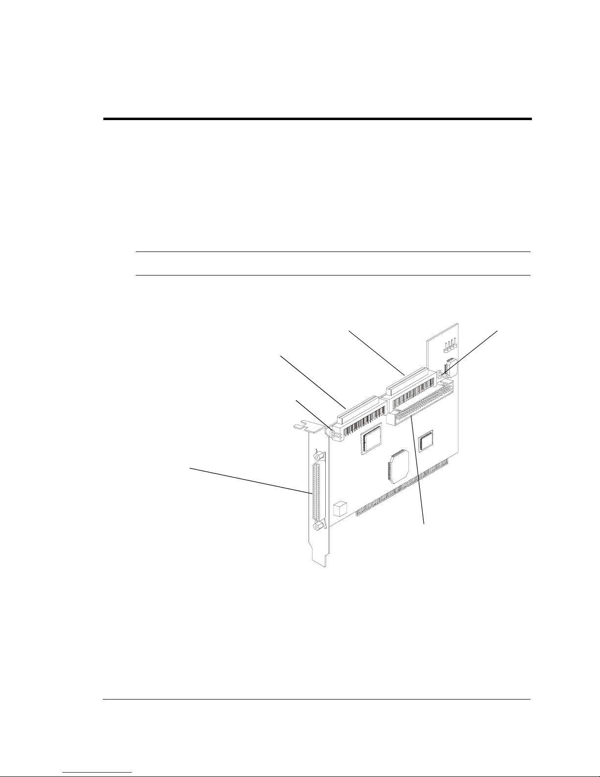
The HP Ultra3 Single Channel SCSI Host Bus Adapter enables you to connect up to
15 SCSI devices—such as hard disk drives, scanners, and CD-ROM drives—to HP
Servers with 32-bit or 64-bit PCI expansion slots. You can connect newer Ultra3 and
Ultra2 SCSI devices to the two 68-pin Low Voltage Differential/Single-Ended
(LVD/SE) connectors. You can also connect legacy SCSI devices to the 68-pin and
50-pin internal Single-Ended (SE) connectors.
NOTE The HP Server tc2110 uses only Ultra3 SCSI devices
68-pin Internal LVD/SE Connector
68-pin External LVD/SE Connector
Figure 1-1. HP Ultra3 Single Channel SCSI Host Bus Adapter
68-pin Internal SE Connector
J2
50-pin Internal SCSI SE Controller
J6
1
Page 8

Chapter 1 Installation and Setup
Although the HP Ultra3 SCSI Host Bus Adapter is a 64-bit PCI host bus adapter, it
also works in a 32-bit PCI slot. When installed in a 32-bit PCI slot, the host bus
adapter automatically runs in the slower 32-bit mode. This installation guide
explains how to:
· Install the HP Ultra3 SCSI host bus adapter
· Set up SCSI devices
· Connect SCSI devices
Where to Obtain Installation Instructions
Complete installation and removal instructions can be found in both of the following
sources:
· The HP Server Operations and Maintenance Guide, on the HP Server Online
Documentation CD-ROM shipped with your HP Server, has a complete chapter
on installing and configuring the HP Server.
· The HP Server Operations and Maintenance Guide for your HP Server can be
viewed and printed from the official HP Server web site:
http://www.hp.com
Bus Segments on the HP Ultra3 SCSI Host
Adapter
The HP Ultra3 SCSI host bus adapter features technology that ensures you get the
best performance from your Ultra3 and Ultra2 SCSI devices by electronically
isolating the primary LVD/SE segment from the secondary SE segment on the SCSI
bus. This allows the HP Ultra3 SCSI host bus adapter to support newer Ultra3 and
Ultra2 SCSI devices at speeds up to 160 MBytes/sec on the primary LVD/SE
segment while at the same time supporting Ultra (legacy) devices at speeds up to 40
MBytes/sec on the secondary SE segment. The following figure shows the two SCSI
segments.
2
Page 9

Chapter 1 Installation and Setup
Primary LVD/SE Segment
Figure 1-2. Primary and Secondary Bus Segments
Secondary LVD/SE Segment
NOTE If you attach Wide Ultra or Ultra SCSI devices to the LVD/SE
connector(s), the data transfer rate for all attached Ultra3 and
Ultra2 SCSI devices will drop to Ultra SCSI performance
levels. However, if you attach only Ultra3 and Ultra2 SCSI
devices to the LVD/SE connector(s), data will be transferred at
the maximum possible rate (80 MBytes/sec for Ultra2 devices
and 160 MBytes/sec for Ultra3 devices).
Installing the HP Ultra3 SCSI Host Bus Adapter
1. Discharge any static electricity build-up before handling the SCSI host bus
adapter by touching a grounded metal object (like the exposed metal parts on the
back of your HP Server).
WARNING Turn OFF power to the HP Server and disconnect the power
2. After you turn off your HP Server and unplug the power cord, remove the cover
from the Server.
cord.
3
Page 10
Chapter 1 Installation and Setup
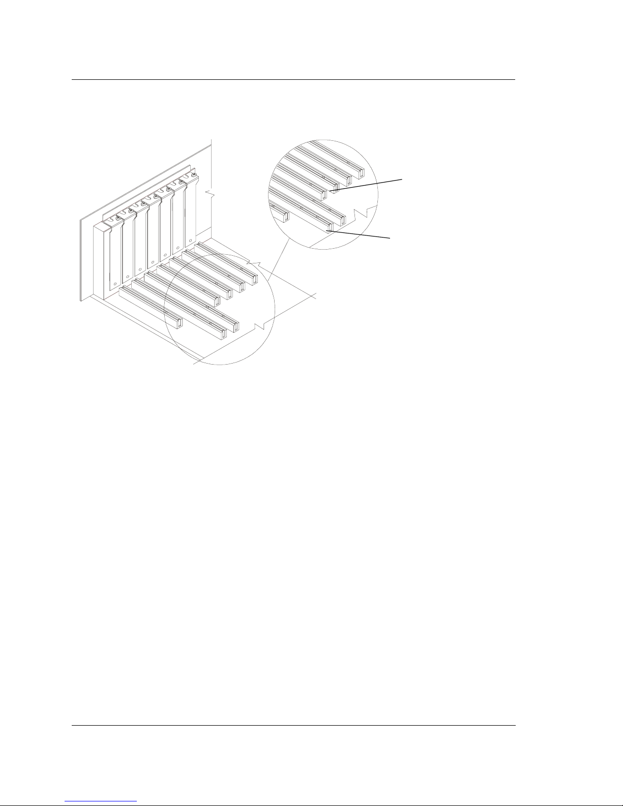
32-bit PCI Slot
64-bit PCI Slot
Figure 1-3. 32-bit and 64-bit Expansion Slots
3. Locate an unused 64-bit PCI expansion slot and remove the expansion slot
cover. If the HP Server does not have a 64-bit slot, you can install the host
adapter in a 32-bit PCI slot. (The expansion slot must be compliant with PCI
Rev. 2.1 or higher and must support bus mastering.)
4
Page 11
Chapter 1 Installation and Setup
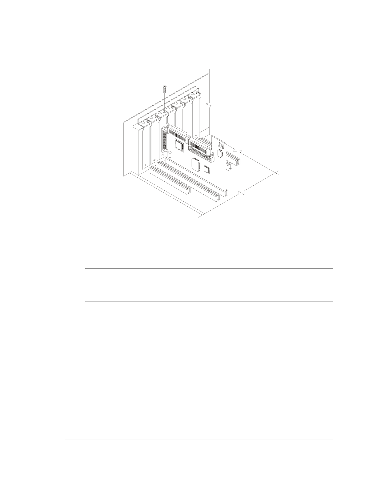
Figure 1-4. Host Bus Adapter Installed in 64-bit Slot
HP Servers may have vertical or horizontal expansion slots. Refer to your HP Server
manual to locate the PCI slots.
NOTE Be careful when inserting the HP Ultra3 SCSI host bus
adapter in a PCI slot. Some 32-bit slots will not accommodate
it, and the host adapter may break if you force it into the slot.
4. Insert the HP Ultra3 SCSI host bus adapter into the PCI expansion slot; press
down firmly until the host adapter clicks into place, then replace the slot cover
screw. When installed properly, the host adapter should appear level with the
expansion slot, as shown above.
5
Page 12

Chapter 1 Installation and Setup
Setting Up SCSI Devices
There are several things you may need to do to your SCSI devices before you
connect them to the HP Ultra3 SCSI host bus adapter:
· Check the SCSI IDs
· Set the termination
· Connect the power cables
Since setup can vary from device to device, always refer to the device’s
documentation for specific instructions.
Below are some guidelines for setting SCSI IDs and termination on your devices.
Check the SCSI IDs
The HP Ultra3 SCSI host bus adapter and each device you connect to it must have a
unique SCSI ID number ranging from 0 to 15. No two devices can have the same ID
number. The HP Ultra3 SCSI host bus adapter is preset to SCSI ID 7 and should not
be changed. If your HP Server will boot from a SCSI hard disk, make sure the SCSI
ID of that hard disk is set to 0. (Most SCSI hard disks are preset to SCSI ID 0 at the
factory.) The SCSI IDs for internal devices are usually set with jumpers; SCSI IDs
for external devices are usually set with a switch on the back of the device.
Terminate the Ends
To ensure reliable communication on the SCSI bus, the device at the end of each
cable, or the end of the cable itself, must have a terminator installed (or enabled).
Terminators must be removed, or termination must be disabled, on devices between
the ends of each cable.
Connecting SCSI Devices
You can connect up to 15 SCSI devices to the HP Ultra3 SCSI host bus adapter.
Before connecting devices, be sure to review “Setting Up SCSI Devices” on page 6.
Connecting the SCSI Host Adapter to the Common Tray
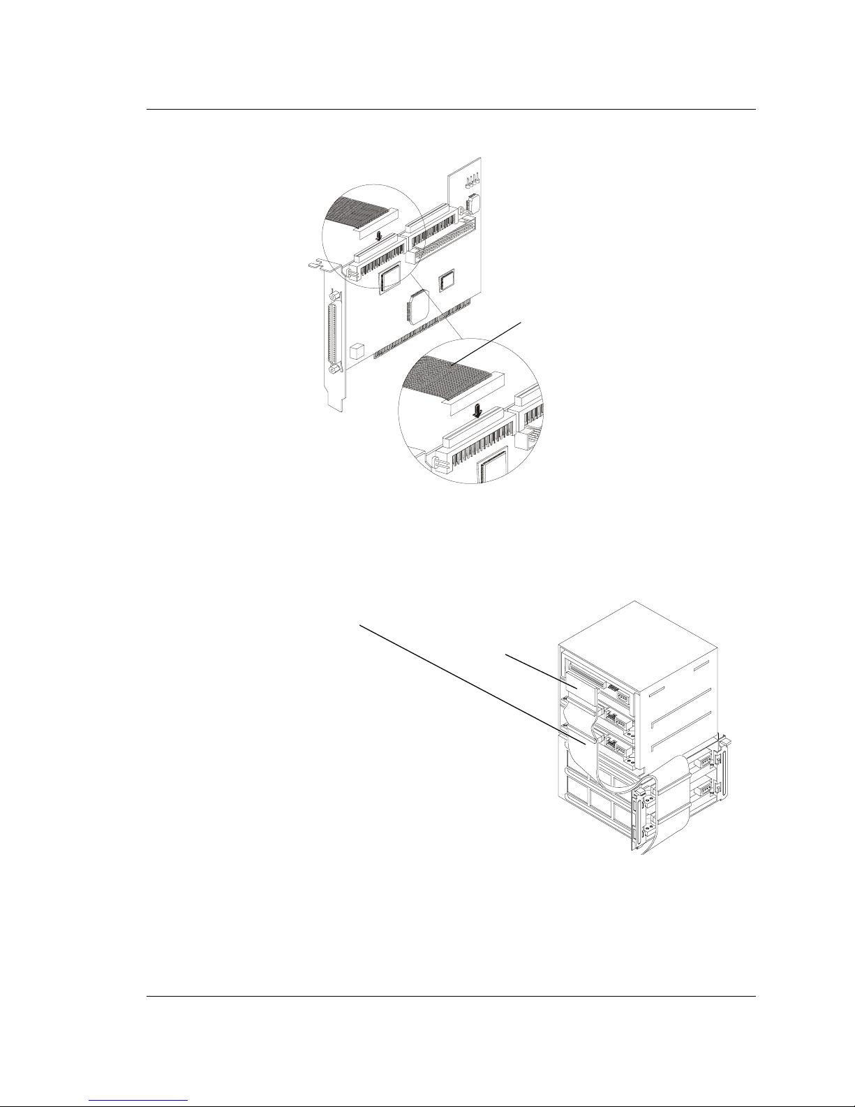
Connect internal Ultra3 SCSI devices to the internal LVD/SE connector on the HP
Ultra3 SCSI host bus adapter. Follow these steps to connect the devices:
1. Use a terminated twisted-pair SCSI cable.
2. Plug the non-terminated end of the twisted-pair cable to the internal LVD/SE
connector (Figure 1-5).
6
Page 13
Chapter 1 Installation and Setup
LVD SCSI Twisted-Pair Cable
Figure 1-5. LVD SCSI Twisted-Pair Cable
3. Plug the internal Ultra3 SCSI devices to the other cable connectors, starting with
the connector at the terminated end of the cable (Figure 1-6).
Terminated LVD SCSI Twisted-Pair Cable
Te rm in at or
Figure 1-6. Common Tray Cable Connection
7
Page 14
Chapter 1 Installation and Setup
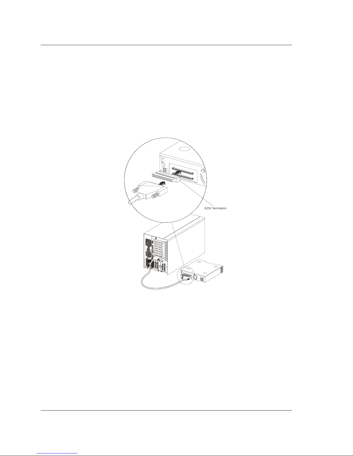
Connecting External SCSI Devices
Connect external Ultra3 SCSI devices to the 68-pin external LVD/SE SCSI
connector. Each external device will require a high density 68-pin external LVD
SCSI cable.
Follow these steps to connect the external devices:
1. Connect one end of the external LVD SCSI cable to the external LVD/SE
connector on the HP Ultra3 SCSI host bus adapter.
Figure 1-7. Connecting External SCSI Devices
2. Connect the other end of the external SCSI cable to a SCSI connector on the
back of an external SCSI device. If you are installing only one external device,
terminate the device and skip to Step 4.
3. Connect other external devices by cabling each device to the previous one, as
shown below.
8
Page 15
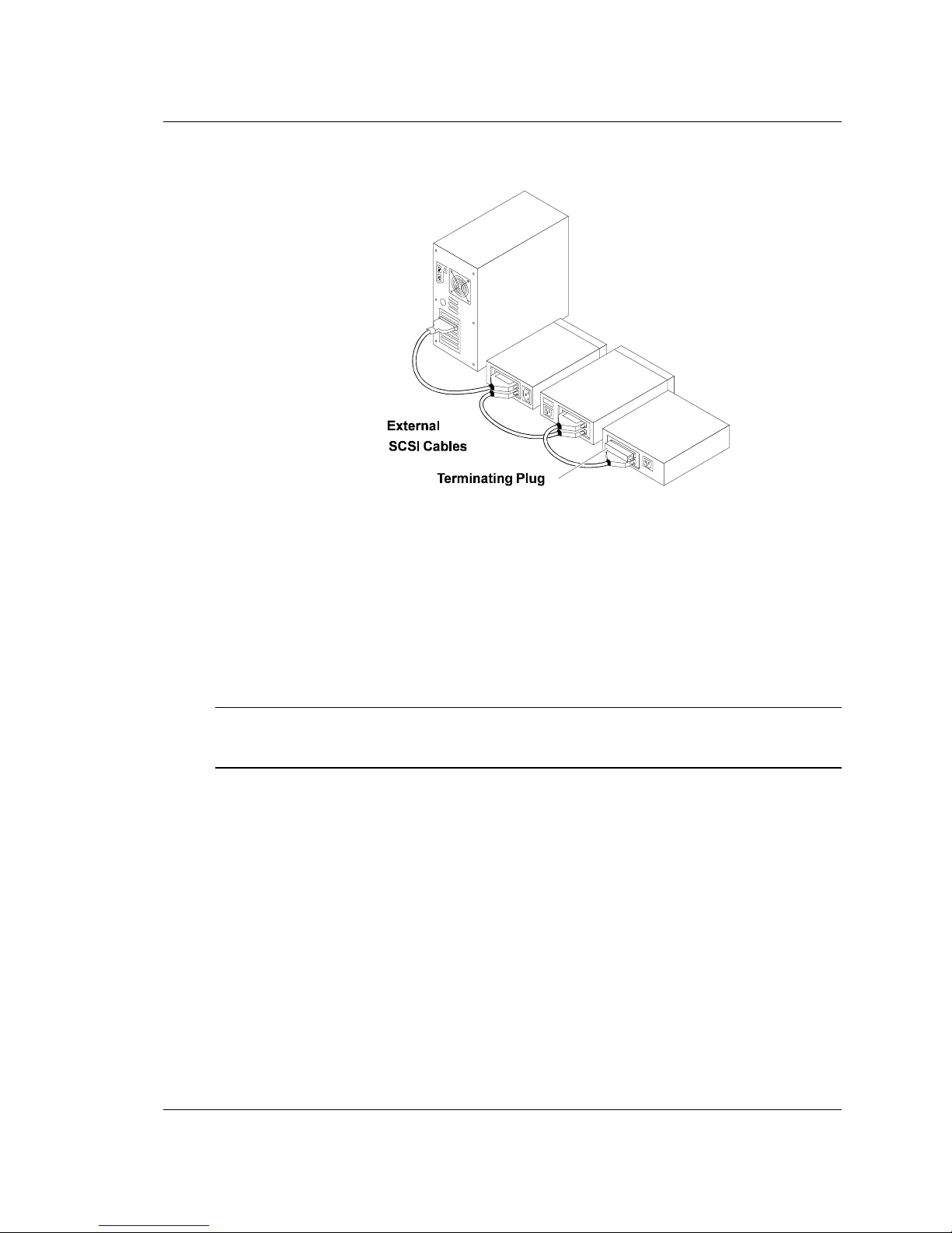
Chapter 1 Installation and Setup
Figure 1-8. Terminating the Last External SCSI Device
4. Terminate only the device at the end of the chain. (Use of an external
multi-mode SCSI terminator is required.)
5. Connect power cables to all external devices and to the HP Server.
HP Ultra3 SCSI Host Adapter Driver Software
NOTE To use the HP Ultra3 SCSI host bus adapter, driver software
must be installed for your operating system.
Preloaded Ultra3 Drivers
If the HP Ultra3 SCSI host bus adapter was included as part of an HP Server you
purchased, then the appropriate HP driver has already been pre-installed by HP and
you do not need to install it.
Embedded Ultra3 Drivers
Some operating systems have embedded driver support for the HP Ultra3 SCSI host
bus adapter. To determine if the host adapter is supported by the operating system
you are using, read the operating system manual or contact the operating system
vendor for information.
9
Page 16

Chapter 1 Installation and Setup
Troubleshooting
If you have any problems while installing the HP Ultra3 SCSI host bus adapter,
check the following items first:
· Are all SCSI devices powered on?
· Are all SCSI cables and power cables properly connected?
· Does each device on the SCSI bus have a unique SCSI ID?
· Does the total SCSI cable length exceed the maximum allowable length? (The
maximum cable length for the Ultra3 SCSI host adapter cannot exceed 12
meters.)
· Is the SCSI bus properly terminated?
If you are still unable to resolve a problem, contact HP Technical Support for help.
10
Page 17

2 Configuration with SCSISelect
SCSISelect, included with the HP Ultra3 SCSI Host Bus Adapter, enables you to
change SCSI settings without opening the computer or handling the host bus adapter.
SCSISelect also enables you to low-level format or verify the disk media of your
SCSI hard disk drives. The following table lists the available and default settings for
each SCSISelect option.
NOTE The default settings are appropriate for most systems. Run
SCSISelect if you need to change or view current settings, or
if you would like to run the SCSI disk utilities.
Table 2-1. SCSI Select Options
Default
SCSISelect Options Available Settings
SCSI Bus Interface Definitions:
Host Adapter SCSI ID 0-15 7
Setting
SCSI Parity Checking Enabled, Disabled Enabled
Host Adapter SCSI Termination
LVD/SE Connectors Automatic, Enabled,
SE Connectors Automatic
Boot Device Options:
Boot SCSI ID 0-15 0
Boot LUN Number
SCSI Device Configuration:
Sync Transfer Rate (MBytes/sec) 160, 80.0, 53.4, 40.0,
Automatic
Disabled
Automatic
Low ON/High ON
Low OFF/High OFF
Low OFF/High ON
1
0-7 0
160
32.0, 26.8, 20.0,
16.0, 13.4, 10.0,
ASYN
11
Page 18

Chapter 2 Configuration with SCSISelect
Table 2-1. SCSI Select Options
Default
SCSISelect Options Available Settings
Setting
Initiate Wide Negotiation Yes, No Yes (Enabled)
Enable Disconnection Yes, No Yes (Enabled)
Send Start Unit Command Yes, No Yes (Enabled)
Enable Write Back Cache
BIOS Multiple LUN Support
Include in BIOS Scan
2
Advanced Configuration Options:
Reset SCSI Bus at IC
Initialization
Display <Ctrl> <A> Messages
during BIOS Initialization
Extended BIOS Translation for
DOS Drives > 1 GByte
Verbose/Silent Mode Verbose, Silent Verbose
Host Adapter BIOS Enabled
Domain Validation
2
1
2
N/C (No Change)
Yes , N o
N/C (No
Change)
Yes, No No (Disabled)
Yes, No Yes (Enabled)
Enabled, Disabled Enabled
Enabled, Disabled Enabled
Enabled, Disabled Enabled
Enabled
Disabled: Not Scan
Disabled: Scan Bus
Enabled, Disabled Enabled
Support Removable Disks Under
BIOS as Fixed Disks
BIOS Support for Bootable
CD-ROM
2
BIOS Support for Int 13
Extensions
1
Setting is valid only if Multiple LUN Support is enabled
2
Settings are valid only if host adapter BIOS is enabled
12
2
Disabled, Boot Only,
2
All Disks
Disabled
Enabled, Disabled Enabled
Enabled, Disabled Enabled
Page 19

Chapter 2 Configuration with SCSISelect
Starting SCSISelect
Follow these steps to start SCSISelect:
1. Turn on or restart your system.
During the startup process, pay careful attention to the messages that appear on
your screen.
2. When the following message appears on your screen, press the Ctrl-A keys
simultaneously (this message appears for only a few seconds):
Press <Ctrl><A> for SCSISelect (TM) Utility!
3. From the menu that appears, use the arrow keys to move the cursor to the option
you want to select, then press Enter.
NOTE If you have difficulty viewing the display, press F5 to toggle
between color and monochrome modes. (This feature may not
work on some monitors.)
Exiting SCSISelect
Follow these steps to exit SCSISelect:
1. Press Esc until a message prompts you to exit (if you changed any settings, you
are prompted to save the changes before you exit).
2. At the prompt, select Yes to exit, then press any key to reboot the computer. Any
changes made in SCSISelect will take effect the next time the computer is
booted.
Using SCSISelect Settings
To select an option, use the arrow keys to move the cursor to the option, then press
Enter.
In some cases, selecting an option displays another menu. You can return to the
previous menu at any time by pressing Esc.
To restore the original SCSISelect default values, press F6 from the main
SCSISelect screen.
13
Page 20

Chapter 2 Configuration with SCSISelect
SCSI Bus Interface Definitions
· Host Adapter SCSI ID—(Default: 7) Sets the SCSI ID for the SCSI host bus
adapter. The Ultra3 SCSI Host Bus Adapter is set at 7, which gives it the highest
priority on the SCSI bus. We recommend that you do not change this setting.
· SCSI Parity Checking—(Default: Enabled) When set to Enabled, verifies the
accuracy of data transfer on the SCSI bus. Leave this setting enabled unless any
SCSI device connected to the Ultra3 SCSI Host Bus Adapter does not support
SCSI parity.
· Host Adapter SCSI Termination—(Default: Automatic) Determines the
termination setting for the SCSI host bus adapter. The default setting for both
the LVD/SE and SE connectors is Automatic, which allows the SCSI host bus
adapter to adjust the termination as needed depending on the configuration of the
connected SCSI devices. We recommend that you do not change this setting.
Boot Device Options
· Boot SCSI ID—(Default: 0) Specifies the SCSI ID of your boot device. We
recommend that you do not change the default setting.
· Boot LUN Number—(Default: 0) Specifies which LUN (Logical Unit
Number) to boot from on your boot device. This setting is not valid unless
Multiple LUN Support is Enabled (see “Advanced Configuration Options” on
page 16).
SCSI Device Configuration
SCSI Device Configuration options can be set individually for each connected SCSI
device.
NOTE To configure settings for a SCSI device, you must know its
SCSI ID (see “Using SCSI Disk Utilities” on page 18).
· Sync Transfer Rate—(Default: 160) Determines the maximum synchronous
data transfer rate that the SCSI host adapter supports. Use the maximum value
of 160 MBytes/sec. If a device is not Ultra160, select the transfer rate of the
device (80, 53, 40, ...).
14
Page 21

Chapter 2 Configuration with SCSISelect
· Initiate Wide Negotiation—(Default: Yes) When set to Yes, the SCSI host bus
adapter attempts 16-bit data transfer (wide negotiation). When set to No, the
SCSI host bus adapter uses 8-bit data transfer unless the SCSI device requests
wide negotiation.
NOTE Set Initiate Wide Negotiation to No if you are using an 8-bit
SCSI device that hangs or exhibits other performance
problems with 16-bit data transfer rate enabled.
· Enable Disconnection—(Default: Yes) When set to Yes, allows the SCSI
device to disconnect from the SCSI bus. Leave the setting at Yes if two or more
SCSI devices are connected to the SCSI host bus adapter. If only one SCSI
device is connected, changing the setting to No results in slightly better
performance.
· Send Start Unit Command—(Default: Yes) When set to Yes, the Start Unit
Command is sent to the SCSI device at bootup.
The following three options have no effect when the SCSI host bus adapter BIOS is
disabled. (The SCSI host bus adapter BIOS is normally enabled by default.)
· Enable Write Back Cache—(Default: N/C) Can be used to enable or disable
the write-back cache on SCSI disk drives connected to the host adapter. Leave
this option at its default setting of N/C (no change), which usually allows for
optimum drive performance.
· BIOS Multiple LUN Support—(Default: No) Leave this setting at No if the
device does not have multiple Logical Unit Numbers (LUNs). When set to Yes,
the SCSI host bus adapter BIOS provides boot support for a SCSI device with
multiple LUNs (for example, a CD “juke box” device in which multiple CDs can
be accessed simultaneously).
· Include in BIOS Scan—(Default: Yes) When set to Yes, the SCSI host bus
adapter BIOS includes the device as part of its BIOS scan at bootup.
15
Page 22

Chapter 2 Configuration with SCSISelect
Advanced Configuration Options
NOTE Do not change the Advanced Configuration Options unless
absolutely necessary.
· Reset SCSI Bus at IC Initialization—(Default: Enabled) When set to Enabled,
the SCSI host bus adapter generates a SCSI bus reset during its power-on
initialization and after a hard reset.
· Display <Ctrl> <A> Messages during BIOS Initialization—(Default:
Enabled) When set to Enabled, the SCSI host bus adapter BIOS displays the
Press <Ctrl> <A> for SCSISelect (TM) Utility!
message on your screen during system bootup. If this setting is disabled, you can
still invoke the SCSISelect Utility by pressing <Ctrl> <A> after the SCSI host
bus adapter BIOS banner appears.
· Extended BIOS Translation for DOS Drives > 1 GByte—(Default: Enabled)
When set to Enabled, provides an extended translation scheme for SCSI hard
disks with capacities greater than 1 GByte. This setting is necessary only for
MS-DOS 5.0 or above; it is not required for other operating systems, such as
NetWare or UNIX.
16
CAUTION Changing the translation scheme destroys all data on the drive.
Be sure to back up the data before changing the translation
scheme.
Use the MS-DOS Fdisk command to partition a disk larger than 1 GByte controlled
by the SCSI host bus adapter BIOS, when using DOS, Windows 3.1.x, or Windows
95/98.
· Verbose/Silent Mode—(Default: Verbose) When set Verbose, the SCSI host
bus adapter BIOS displays the host adapter model on the screen during system
bootup. When set to Silent, the message will not be displayed during bootup.
· Host Adapter BIOS (Configuration Utility Reserves BIOS Space)—
(Default: Enabled) Enables or disables the SCSI host bus adapter BIOS.
o Leave at Enabled to allow the SCSI host bus adapter BIOS to scan and
initialize all SCSI devices.
Page 23

Chapter 2 Configuration with SCSISelect
oSet to Disabled: Not scan if the devices on the SCSI bus (for
example, CD-ROM drives) are controlled by software drivers and do not
need the BIOS, and you do not want the BIOS to scan the SCSI bus.
o Set to Disabled: Scan Bus if you do not need the BIOS, but you want it to
scan the SCSI devices on the bus.
The following four options have no effect when the SCSI host bus adapter BIOS is
disabled. (The SCSI host bus adapter BIOS is normally enabled by default.)
· Domain Validation—(Default: Enabled) Determines the kinds of SCSI devices
connected and reduces data transfer speed when legacy SCSI devices are
detected. Displays the resulting data transfer rate.
· Support Removable Disks Under BIOS as Fixed Disks—(Default: Disabled)
Determines which removable-media drives are supported by the SCSI host bus
adapter BIOS. Choices are as follows:
o Disabled— No removable-media drives are treated as hard disk drives.
Software drivers are required because the drives are not controlled by the
BIOS.
CAUTION You may lose data if you remove a removable-media cartridge
from a SCSI drive controlled by the SCSI host bus adapter
BIOS while the drive is on. If you want to be able to remove
the media while the drive is on, install the removable-media
software driver and set Support Removable Disks Under
BIOS as Fixed Disks to Disabled.
o Boot Only—Only the removable-media drive designated as the boot device
is treated as a hard disk drive.
o All Disks—All removable-media drives supported by the BIOS are treated
as hard disk drives.
· BIOS Support for Bootable CD-ROMs—(Default: Enabled) When set to
Enabled, the SCSI host bus adapter BIOS allows the computer to boot from a
CD-ROM drive.
· BIOS Support for Int 13 Extensions—(Default: Enabled) When set to
Enabled, the SCSI host bus adapter BIOS supports Int 13h extensions as
required by Plug-and-Play. The setting can be either enabled or disabled if your
system is not Plug-and-Play.
17
Page 24

Chapter 2 Configuration with SCSISelect
Using SCSI Disk Utilities
To access the SCSI disk utilities, follow these steps:
1. Select the SCSI Disk Utilities option from the menu that appears after starting
SCSISelect. SCSISelect scans the SCSI bus (to determine the devices installed)
and displays a list of all SCSI IDs and the devices assigned to each ID.
2. Use the arrow keys to move the cursor to a specific ID and device, then press
Enter.
3. A small menu appears, displaying the options Format Disk and Verify Disk
Media.
o Format Disk—Allows you to perform a low-level format on a hard disk
drive. Most SCSI disk devices are preformatted at the factory and do not need
to be formatted again.
CAUTION A low-level format destroys all data on the drive. Be sure to
back up your data before performing this operation. You
cannot abort a low-level format once it has started.
o Verify Disk Media—Allows you to scan the media of a hard disk drive for
defects. If the utility finds bad blocks on the media, it prompts you to reassign
them; if you select yes, those blocks are no longer used. Pressing Esc at any
time aborts the utility.
18
Page 25

3 Microsoft Windows NT Installation
This chapter explains how to install the HP Ultra3 Family Manager Set driver <File
Name>adpu160m.sys for Windows NT.
If you are performing a first time Windows NT installation, see “Installing the
Driver When Windows NT is Already Installed” in the next section. If Windows NT
is already installed in your system, see “Installing the Driver When Windows NT is
Already Installed” on page 20.
Installing the Driver When Installing
Windows NT
The <File Name>adpu160m.sys driver is not embedded on the Windows NT 4.0
installation disks (or CD-ROM) and must be added during Windows NT installation.
Completing a Fresh Windows NT 4.0 Installation From Floppy
Disk
1. Start your system with the Windows NT Boot Disk in the floppy disk drive.
2. When prompted, insert disk #2 in your floppy disk drive. After a few moments
you will see a blue screen. To set up Windows NT now, press Enter.
3. Press S to skip auto-detection of your SCSI host adapter.
4. Press S again to specify an additional device.
5. Press Enter to select Others; insert the HP Ultra3 Family Manager Set disk for
Windows NT into your floppy disk drive.
6. Using the arrow keys, select the following driver and press Enter:
Adaptec Ultra3 PCI SCSI Controller (NT4.0)
7. To add other host adapters, press S and repeat from Step 5 for each additional
adapter and insert the appropriate driver disk.
8. Press Enter to continue with the Windows NT operating system setup. Follow
the instructions on-screen and in the Windows NT documentation to complete
the installation.
19
Page 26

Chapter 3 Microsoft Windows NT Installation
Completing a Fresh Windows NT 4.0 Installation From CD-ROM
1. Insert the Windows NT 4.0 CD into the CD-ROM drive.
2. Start your system. Press the F6 key when you see the following message:
"Setup is inspecting your computer’s hardware
configuration..."
3. If you do not see this message, your system may not be setup to boot from a CDROM. You will need to install from floppy disks. See “Completing a Fresh
Windows NT 4.0 Installation From Floppy Disk” on page 19.
4. When prompted, press S to specify an additional device.
5. Press Enter to select Others; insert the HP Ultra3 Family Manager Set disk for
Windows NT into your floppy disk drive.
6. Using the arrow keys, select the following driver and press Enter:
Adaptec Ultra3 PCI SCSI Controller (NT4.0)
7. To add other host adapters, press S and repeat from Step 4 for each additional
adapter and insert the appropriate driver disk.
8. Press Enter to continue with the Windows NT operating system setup. Follow
the instructions on-screen and in the Windows NT documentation to complete
the installation.
Installing the Driver When Windows NT is
Already Installed
To update or install the <File Name>adpu160m.sys driver if Windows NT 4.0 is
already installed, follow the instructions below.
Updating Windows NT 4.0
1. Start Windows NT.
2. Click the Start button on the Windows NT task bar, and then point to Settings.
3. Click the Control Panel.
4. Double-click the SCSI Adapters icon.
5. Click the Drivers tab, and then click the Add button.
6. In the Install Driver window, click the Have Disk button.
20
Page 27

Chapter 3 Microsoft Windows NT Installation
7. Insert the HP Ultra3 Family Manager Set disk for Windows NT into drive A.
8. From the Copy Manufacturer’s File From text box, type a:\nt4, and click OK.
9. In the Install Driver window, Click OK.
10. Click the New button when asked if you want to use the currently installed
driver(s) or install new one(s).
11. Type a:\nt4 again, and click Continue. The driver is now installed.
12. You must restart your computer for the changes to take effect. Click Yes to
restart your computer. Click No to return to the SCSI Adapters window.
Using Advanced Configuration Parameters
Advanced users may use software parameters to alter the configuration of the
Windows NT device drivers supplied by HP. All Windows NT configuration
information is stored in a data structure called the Registry. You can edit this
information through a tool called the Registry Editor.
CAUTION Do not edit your registry unless it is absolutely necessary. If
there is an error in your registry, your server may become
nonfunctional.
Using Windows NT SCSI Parameters
Follow the instructions below to enter the registry values that affect how the
Windows NT SCSI manager interprets the generic configuration information of
SCSI device drivers. All SCSI host adapters installed in your system are affected by
the values you enter here. A list of valid values follows:
NOTE The following value keys are case-sensitive and must be
entered exactly as shown.
· DisableTaggedQueuing — A nonzero value indicates that the SCSI host
adapter disables tagged queueing for SCSI devices. The data type for this value
is REG_SZ.
21
Page 28

Chapter 3 Microsoft Windows NT Installation
· DisableSynchronousTransfers — A nonzero value indicates that the SCSI
host adapter is not to initiate synchronous negotiations (but it may still accept
negotiations initiated by a SCSI target). The data type for this value is REG_SZ.
· DisableDisconnects — A nonzero value indicates that targets are not permitted
to disconnect during the execution of a SCSI command. The data type for this
value is REG_DWORD.
· MaximumLogicalUnit — This can limit the scan for connected devices on the
SCSI bus. Valid values are 1 to 8. If 1 is specified, the Windows NT SCSI
manager assumes that no SCSI targets support LUNs other than 0. Otherwise,
LUNs from 0 to 8 are scanned during system initialization. The data type for this
value is REG_DWORD.
· Maximum SGList — Specifies the maximum number of Scatter/Gather
elements. Valid values are 17-255. The data type for this value is
REG_DWORD.
To enter Windows NT parameters, follow these steps:
1. Select Run from the Start button.
2. Type regedt32 and press Enter.
3. Open the registry list to the following location:
\HKEY_LOCAL_MACHINE\System\CurrentControlSet\
Services\adpu160m\Parameters\Device
If the Parameters Device keys already exist, skip to Step 8 below to begin
entering values. If the keys do not yet exist, you will need to create them by
continuing with Step 4.
4. Click on the adpu160m key.
5. Select Add Key from the Edit menu; Type Parameters in the Key Name edit box.
Leave the Class edit box blank.
6. Click on the Parameters key.
7. Select Add Key from the Edit menu; Type Device in the Key Name edit box.
Leave the Class edit box blank.
8. To specify a certain host adapter, append Device with the number of the host
adapter. For example, type Device0 for the first host adapter, Device1 for the
second, etc. If you omit the host adapter number, the configuration information
applies to all Ultra3 Family host adapters.
22
Page 29

Chapter 3 Microsoft Windows NT Installation
9. Click on the Device key.
10. Select Add Value from the Edit menu. In the Value Name edit box, enter one of
the valid parameter values. Make sure to enter the appropriate data type for the
value. To enter additional values, repeat Step 8 through Step 9.
NOTE Changes made with the Registry Editor do not take effect until
you shut down and then restart your system.
Using Driver-specific Parameters
To use the Registry Editor to enter <File Name>adpu160m.sys driver-specific
parameters that affect the configuration information for SCSI PCI device drivers,
follow the instructions below. A list of valid parameters follows:
NOTE The following parameters are case-sensitive and must be
entered exactly as shown. When entering multiple parameters,
each parameter must be separated by a space.
· /INSTRUMENTATION—enables recording of I/O statistics and errors. If this
option is not specified, instrumentation defaults to disabled. The data type for
this value is REG_SZ.
· /INSTR_ERRLOG_Z=nnn—sets the maximum number of error log entries, if
/INSTRUMENTATION is enabled. If a number is not specified, the maximum
number or error log entries defaults to 32. Valid values are 0-128. The data type
for this value is REG_SZ.
· /MAXTAGS=nnn—specifies the tagged command queue depth. If a number is
not specified, the tagged queue depth defaults to 128. Valid values are 1-255.
The data type for this value is REG_SZ.
· /HOTPLUG —enables Hot-Plug PCI feature. If this option is not specified,
Hot-Plug PCI feature defaults to disabled.
To enter driver-specific parameters, follow these steps:
1. Select Run from the Start button.
2. Type regedt32 and press Enter.
3. Open the registry list to the following location:
23
Page 30

Chapter 3 Microsoft Windows NT Installation
\HKEY_LOCAL_MACHINE\System\CurrentControlSet\
Services\adpu160m\Parameters\Device\DriverParameters
If the Parameters, Device, and Driver Parameters keys already exist, skip to Step 10
below to begin entering parameters. If the keys do not yet exist, you will need to
create them by continuing with Step 4.
4. Click on the adpu160m key.
5. Select Add Key from the Edit menu; Type Parameters in the Key Name edit box.
Leave the Class edit box blank.
6. Click on the Parameters key.
7. Select Add Key from the Edit menu; Type Device in the Key Name edit box.
Leave the Class edit box blank.
To specify a certain host adapter, append Device with the number of the host
adapter. For example, type Device0 for the first host adapter, Device1 for the
second, etc. If you omit the host adapter number, the configuration information
applies to all Ultra3 host adapters.
8. Click on the Device key.
9. Select Add Value from the Edit menu; type Driver Parameters in the Key Name
edit box. Enter REG_SZ as the data type and press Enter.
10. A String Editor text box appears. Enter valid parameters in the text box. When
entering multiple parameters, each parameter must be separated by a space.
NOTE Changes made with the Registry Editor do not take effect until
you shut down and then restart your system.
Hot-Plug PCI Feature
Hot-Plug PCI is supported by the Windows NT 4.0 driver adpu160m.sys. You will
need a system that supports Hot-Plug PCI as well as associated Hot-Plug PCI
application software in order for Hot-Plug PCI to work. Do not enable the Hot-Plug
PCI feature unless your system is Hot-Plug PCI capable and you wish to use the HotPlug PCI feature.
Follow the instructions below to enable Hot-Plug PCI support in the driver:
1. Insert the HP Ultra3 Family Manager Set disk for Windows NT into drive A.
2. Select Run from the Start menu.
24
Page 31

Chapter 3 Microsoft Windows NT Installation
3. Type a:\nt4\hotp160m.reg and press Enter.
4. Click OK.
5. Reboot the system.
6. See the note following these instructions.
NOTE The file hotp160m.reg adds Hot-Plug related entries into the
NT Registry, including the driver-specific registry value /
HOTPLUG. Running hotp160m.reg will overwrite your
current driver-specific registry values located at:
\HKEY_LOCAL_MACHINE\System\CurrentControlSet\
Services\adpu160m\Parameters\Device\DriverPar
ameters
If you have previously added other driver specific registry
values, you should note them before running the
hotp160m.reg file. After running hotp160m.reg, you may
verify and restore those previously added driver-specific
registry values, if needed.
Using Windows NT and the Host Adapter
This section contains useful information on using Windows NT and your host
adapter.
Removing a Host Adapter
Removing a host adapter can be as simple as physically removing it from the slot
when your computer is shut down. Windows NT boots and functions properly in this
configuration, but a Warning message is generated every time you boot Windows
NT.
CAUTION If you have removed a host adapter but still have other host
adapters of the same type installed in your computer, do not
use Windows NT Setup to remove the device driver.
To eliminate the Warning message, you must update the Windows NT software
configuration, as described below:
25
Page 32

Chapter 3 Microsoft Windows NT Installation
Removing a Host Adapter in Windows NT 4.0
1. From the Control Panel, double-click the SCSI Adapters icon.
2. Click the Drivers tab.
3. Using the arrow keys select the following driver:
Adaptec 29160(N), 29160, 39160, AHA-3960D, AIC-7892/
7899 Ultra160 PCI SCSI Controller (NT 4.0)
4. Click the Remove button.
5. If you are sure you are removing the correct host adapter type, click Yes.
6. Click Yes to restart the computer and initialize changes. Click No to return to
the SCSI Adapters window.
NOTE Windows NT Setup does not delete the device driver from
your system disk; it only updates Windows NT software
configuration information so that the device driver is no
longer loaded during system bootup.
Troubleshooting
Problems and Solutions
I made changes to the host adapter configuration and Windows NT no longer
boots!
The boot manager for Windows NT contains recovery logic to allow you to return
to the last known good configuration. If you have changed your host adapter
configuration and Windows NT no longer boots, follow these steps to recover:
1. Undo any hardware changes you have made to the server since it was last
operational.
2. Reboot the server. Watch the display carefully during bootup. If the following
message appears, press the Spacebar and follow the instructions on-screen to
continue booting with the last known good configuration:
Press spacebar NOW to invoke the Last Known Good menu
26
Page 33

Chapter 3 Microsoft Windows NT Installation
3. Once your server is operational again, check all of the hardware and software
configuration changes you want to make. Look specifically for conflicts with
parts of the existing system configuration that are not being changed.
Error Messages
Error messages generated by the <File Name>adpu160m.sys driver can be viewed
by opening the Windows NT Event Viewer error logs.
To view events generated by the driver, follow these steps:
1. Double-click the Event Viewer icon in the Administrative Tools program group.
Error messages generated by the driver show up as Event ID 11. Error messages
generated by the SCSI port show up as Event ID 9.
2. To view event details, select System from the Log menu. Double-click the <File
Name>adpu160m.sys driver event that has an Event ID of 11. (There may be
none or multiple driver events.)
The top portion of the Event Detail dialog box displays information such as the
time that the event was generated, the computer on which the event occurred (in
case of remote monitoring), and the description of the event. The Data section
of the Event Details dialog box displays the error messages generated.
3. Click the Words radio button.
In the Data section of the dialog box, the entry in the second row and second
column (to the right of the 0010: entry) lists the error message generated by the
driver. The common error messages for the driver are described below.
NOTE The entry in the third row of the last column identifies the
SCSI ID of the device originating the error.
adpu160m.sys Error Messages
The following error messages are listed sequentially according to the last three digits
of the error message. For example, [xxxxx010], [xxxxx011], [xxxxx012], etc.
NOTE When reporting problems to HP Customer Support, be sure to
include the complete error message in your problem
description.
27
Page 34

Chapter 3 Microsoft Windows NT Installation
[xxxxx004] Command completed with error
[xxxxx005] Command completed with error
[xxxxx006] Command completed with error
A request issued to a target device completed with indication that there is an error.
In most cases, the error is recovered and normal operations continues.
[xxxxx010] Error issuing command
An error has occurred while the driver was setting up its internal data structures.
[xxxxx011] Error issuing command
The requested command is not supported by this driver.
[xxxxx012] Error issuing command
[xxxxxx99] Error issuing command
The driver does not recognize the target device.
[xxxxx021] Target device protocol error
An unexpected event occurred during data transfer between the adapter and target
device. Normally, this indicates a faulty or non-compliant target device.
[xxxxx022] Adapter or target device protocol error
The adapter or target device has broken the communication protocol. A badly
behaving device could cause this message to appear. Normally this is not a serious
problem. If you get this message frequently over a short period of time, it could
indicate that the device or system is malfunctioning. Unplug or power down unused
devices to see if the problem persists.
[xxxxx023] Target device parity error
The driver has detected a parity error by the target device.
[xxxxx024] Data overrun or underrun
The adapter was given more or less data than the expected amount of data.
[xxxxx031] Target device queue full
The target device internal buffer is full.
28
Page 35

Chapter 3 Microsoft Windows NT Installation
[xxxxx032] Target device busy
The target device reports a Busy status. Another program may already be using this
device.
[xxxxx050] Host adapter failure
[xxxxxx9A] Host adapter failure
Your host adapter may not be properly installed or is defective. Try resetting the
adapter in the PCI slot, or try installing it a different PCI slot.
[xxxxx081] Adapter initialization failure
[xxxxxx8A] Adapter initialization failure
[xxxxxx83] Adapter initialization failure
An error has occurred while the driver was setting up its internal data structures.
Verify that your adapter is supported by this version of the driver.
[xxxxx089] Unable to allocate memory
This indicates that there may be a problem with the amount of memory installed in
your system. Verify that your system has at least the minimum amount of memory
required by your operating system.
[xxxxx096] Adapter hardware initialization failure—possible resource
conflict
The driver has attempted to initialize the adapter hardware but failed. This might
suggest that the adapter resources (e.g., IRQ) conflict with another board installed
in your system.
[xxxxx097] Unable to allocate memory
This indicates that there may be a problem with the amount of memory installed in
your system. Verify that your system has at least the minimum amount of memory
required by your operating system.
[xxxxx0af] Unable to de-allocate memory that was allocated for a target
device
Normally, this is not a serious problem, unless you get this message frequently over
a short period of time. The memory can be reclaimed by rebooting the system.
29
Page 36

Chapter 3 Microsoft Windows NT Installation
[xxxxx0ce] Scatter/gather limit exceeded
An I/O request packet from the system contained a Scatter/Gather element list that
contained more elements than are supported by the miniport. Scatter/Gather is a list
of data segments that define the entire data transfer. Scatter/Gather is a means to
improve total data throughput. This error might be caused by a component external
to the miniport driver, such as the operating system or an ASPI application.
[xxxxxd4] Adapter hardware failure - adapter reset
The host adapter hardware failed and the miniport has to reset the hardware.
[xxxxx0d6] Internal driver error
An error has occurred while the driver was setting up its internal data structures. Try
installing the most up-to-date version of the driver available from the HP Web site
located at:
http://www.hp.com
30
Page 37

4 Microsoft Windows 2000
Installation
This chapter explains how to install the HP Ultra3 Family Manager Set driver for
Windows 2000.
If you are performing a first-time Windows 2000 installation, see “Installing the
Driver When Installing Windows 2000” . If Windows 2000 is already installed in
your system, see “Installing the Driver When Windows 2000 is Already Installed”
on page 32.)
Installing the Driver When Installing
Windows 2000
1. Start your system with the Windows 2000 Operating System CD-ROM disk in
your CD-ROM drive.
NOTE When using a CD-ROM drive to install Windows 2000 from
the bootable CD-ROM, make sure Bootable CD-ROM
support is enabled in either the system or SCSI BIOS setup
utility. If these options are not available, boot from the
Windows 2000 floppy disks.
2. You may see a message:
Press any key to boot from CD.
3. After Windows 2000 has completed installation, please reinstall your SCSI
driver from the Device Manager. Follow the steps in “Installing the Driver
When Windows 2000 is Already Installed” on page 32 to ensure the desired
driver is installed.
31
Page 38

Chapter 4 Microsoft Windows 2000 Installation
Installing the Driver When Windows 2000 is
Already Installed
To update or install the driver if Windows 2000 is already installed, follow these
instructions:
1. Start Windows 2000.
2. Click the Start button on the Windows 2000 task bar, and then point to Settings.
3. Click the Control Panel.
4. Double-click the System icon.
5. Select the Hardware tab and click the Device Manager button.
6. Under SCSI and RAID Controllers, click on the + sign to the left. This will
display the SCSI adapters currently installed. Right-click on the device you wish
to update and select Properties.
7. Click the Driver tab and click the Update Driver button. The Update Device
Driver Wizard will start. Click Next.
8. Select the “Search for a suitable driver” option and click Next.
9. Select the location where the updated driver is installed and click Next.
10. At this step, Windows 2000 will recommend one of two choices. If it
recommends using the driver found on the driver disk, then click Next and skip
to Step 12. It might recommend that you keep the existing driver and mention
that it found other suitable drivers. If this is the case, select “Install one of the
other drivers” and click Next.
11. You may be asked to enter the path for the driver.
\win2000\ultra160\adpu160m.sys
12. Click Finish. You may be required to reboot your system.
32
Page 39

Chapter 4 Microsoft Windows 2000 Installation
Upgrading an Existing Windows NT Version 4
Installation to Windows 2000
1. With your operating system started, insert your Windows 2000
CD-ROM and choose to upgrade your system. Your system will reboot.
2. The Windows 2000 Setup program will start. Press F6 when this message is
displayed:
Press F6 if you need to install a third party SCSI or
RAID driver...
3. Follow the directions from “Installing the Driver When Installing
Windows 2000” on page 31.
Using Advanced Configuration Parameters
Advanced users may use software parameters to alter the configuration of the
Windows 2000 device drivers supplied by HP. All Windows 2000 configuration
information is stored in a data structure supplied by Windows 2000, called the
Registry. You can edit this information through a tool called the Registry Editor.
CAUTION Do not edit your registry unless it is absolutely necessary. If
there is an error in your registry, your computer may become
nonfunctional.
Using Windows 2000 SCSI Parameters
Follow the instructions below to enter the registry values that affect how the
Windows 2000 SCSI manager interprets the generic configuration information of
SCSI device drivers. Each driver has its own key reference in the registry. In this
example, the Ultra160 key is used (adpu160m). The other keys are aic78xx, aic78u2,
adf6u160, and 2930u2. All SCSI host adapters supported by the modified key are
affected by the values you enter here. A list of valid values follows:
NOTE The following value keys are case-sensitive and must be
entered exactly as shown.
33
Page 40

Chapter 4 Microsoft Windows 2000 Installation
· DisableTaggedQueuing — A nonzero value indicates that the SCSI host
adapter disables tagged queueing for SCSI devices. The data type for this value
is REG_SZ.
· DisableDisconnects — A nonzero value indicates that targets are not allowed
to disconnect during the execution of a SCSI command. The data type for this
value is REG_DWORD.
· DisableMultipleRequests— This limits the number of commands to each
logical device to one. The data type for this value is REG_DWORD.
· MaximumLogicalUnit — This can limit the scan for connected devices on the
SCSI bus. Valid values are 0 to 7. If 1 is specified, the Windows 2000 SCSI
manager assumes that no SCSI targets support LUNs other than 0. Otherwise,
LUNs from 0 to 7 are scanned during system initialization. The data type for this
value is REG_DWORD.
· MaximumSGList — Specifies the maximum number of Scatter/Gather
elements. Valid values are 17-255. The data type for this value is
REG_DWORD.
To enter Windows 2000 parameters, follow these steps:
1. Select Run from the Start button.
2. Type regedt32 and press Enter.
3. Open the registry list to the following location:
\HKEY_LOCAL_MACHINE\System\CurrentControlSet\
Services\adpu160m\Parameters\Device
If the Parameters\Device keys already exist, skip to Step 8 below to begin
entering values. If the keys do not yet exist, you will need to create them by
continuing with Step 4.
4. Click on the adpu160m key.
5. Select Add Key from the Edit menu; type Parameters in the Key Name edit box.
Leave the Class edit box blank.
6. Click on the Parameters key.
7. Select Add Key from the Edit menu; type Device in the Key Name edit box.
Leave the Class edit box blank.
34
Page 41

Chapter 4 Microsoft Windows 2000 Installation
8. To specify a certain host adapter, append Device with the number of the host
adapter. For example, type Device0 for the first host adapter, Device1 for the
second, etc. If you omit the host adapter number, the configuration information
applies to all Ultra3 host adapters.
9. Click on the Device key.
10. Select Add Value from the Edit menu. In the Value Name edit box, enter one of
the valid parameter values. Make sure to enter the appropriate data type for the
value. To enter additional values, repeat Step 8 through Step 9.
NOTE Changes made with the Registry Editor do not take effect until
you restart your system.
Using Driver-specific Parameters
Follow the instructions below to enter the registry values that affect the
configuration information for SCSI PCI device drivers. Each driver has its own key
reference in the registry. In this example, the Ultra160 key is used (adpu160m). The
other keys are aic78xx, aic78u2, adf6u160, and 2930u2. All SCSI host adapters
supported by the modified key are affected by the values you enter here. A list of valid
parameters follows:
NOTE The following parameters are case-sensitive and must be
entered exactly as shown. When entering multiple parameters,
each parameter must be separated by a space.
· /MAXTAGS=nnn—specifies the tagged command queue depth. If a number is
not specified, the tagged queue depth defaults to 128. Valid values are 1-255.
The data type for this value is REG_SZ.
· /MEMMAP—when set, the SCSI manager is memory mapped. If this key is not
used, the default is I/O mapped. There are no valid values or default values. The
data type for this value is REG_SZ.
· /BUS_FAIRNESS—when set, the SCSI bus avoids device starvation. There are
no valid values or default values. The data type for this value is REG_SZ.
To enter driver-specific parameters, follow these steps:
1. Select Run from the Start button.
35
Page 42

Chapter 4 Microsoft Windows 2000 Installation
2. Type regedt32 and press Enter.
3. Open the registry list to the following location:
\HKEY_LOCAL_MACHINE\System\CurrentControlSet\
Services\adpu160m\Parameters\Device
If the Parameters\Device keys already exist, skip to Step 10 below to begin
entering parameters. If the keys do not yet exist, you will need to create them by
continuing with Step 4.
4. Click on the adpu160m key.
5. Select Add Key from the Edit menu; Type Parameters in the Key Name edit box.
Leave the Class edit box blank.
6. Click on the Parameters key.
7. Select Add Key from the Edit menu; Type Device in the Key Name edit box.
Leave the Class edit box blank.
To specify a certain host adapter, append Device with the number of the host
adapter. For example, type Device0 for the first host adapter, Device1 for the
second, etc. If you omit the host adapter number, the configuration information
applies to all Ultra3 host adapters.
8. Click on the Device key.
9. Select Add Value from the Edit menu; type DriverParameters in the Value
Name edit box. Enter REG_SZ as the data type and press Enter.
10. A String Editor text box appears. Enter valid parameters in the text box. When
entering multiple parameters, each parameter must be separated by a space.
NOTE Changes made with the Registry Editor do not take effect until
you restart your system.
Troubleshooting
Most problems can be resolved by following the recommendations in the “Problems
and Solutions” below. If you still experience problems after following the
recommendations, continue with the rest of this section.
36
Page 43

Chapter 4 Microsoft Windows 2000 Installation
Problems and Solutions
I made changes to the host adapter configuration and Windows 2000 no longer
boots!
The boot manager for Windows 2000 contains recovery logic to allow you to return
to the last known good configuration. If you have changed your host adapter
configuration and Windows 2000 no longer boots, follow these steps to recover:
1. Undo any hardware changes you have made to the server since it was last
operational.
2. Reboot the server. Watch the display carefully during bootup. When you see the
message “Starting Windows...” appear at the bottom of the screen, press F8.
This opens the Windows 2000 Advanced Options menu. Select the Last Known
Good Configuration option and select a boot profile.
3. Once your server is operational again, check all of the hardware and software
configuration changes you want to make. Look specifically for conflicts with
parts of the existing system configuration that are not being changed.
Error Messages
Error messages generated by the Windows 2000 Driver Set can be viewed by
opening the Windows 2000 Event Viewer error logs.
To view events generated by the driver, follow these steps:
1. Double-click the Event Viewer icon in the Administrative Tools program group.
Error messages generated by the driver show up as Event ID 11. Error messages
generated by the SCSI port show up as Event ID 9.
2. To view event details, select System Log from the Event Viewer tree. Doubleclick the appropriate Windows 2000 driver event that has an Event ID of 11.
(There may be none or multiple driver events.)
The top portion of the Event Detail dialog box displays information such as the
time that the event was generated, the computer on which the event occurred (in
case of remote monitoring), and the description of the event. The Data section
of the Event Details dialog box displays the error messages generated.
3. Click on the Words option.
37
Page 44

Chapter 4 Microsoft Windows 2000 Installation
In the Data section of the dialog box, the entry in the second row and second
column (to the right of the 0010: entry) lists the error message generated by the
driver. The common error messages for the driver are described below.
NOTE The entry in the third row of the last column identifies the
SCSI ID of the device originating the error.
Driver Error Messages
The following error messages are listed sequentially according to the last three digits
of the error message. For example, [xxxxx010], [xxxxx011], [xxxxx012], etc.
NOTE When reporting problems to HP Customer Support, be sure to
include the complete error message in your problem
description.
[xxxxx004] Command completed with error
[xxxxx005] Command completed with error
[xxxxx006] Command completed with error
A request issued to a target device completed with indication that there is an error.
In most cases, the error is recovered and normal operations continue.
[xxxxx010] Error issuing command
An error has occurred while the driver was setting up its internal data structures. Try
installing the most up-to-date version of the driver available from the HP Web site
at:
http://www.hp.com
[xxxxx011] Error issuing command
The requested command is not supported by this driver.
[xxxxx012] Error issuing command
[xxxxxx99] Error issuing command
The driver does not recognize the target device.
38
Page 45

Chapter 4 Microsoft Windows 2000 Installation
[xxxxx021] Target device protocol error
An unexpected event occurred during data transfer between the adapter and target
device. Normally, this indicates a faulty or non-compliant target device.
[xxxxx022] Adapter or target device protocol error
The adapter or target device has broken the communication protocol. A badly
behaving device could cause this message to appear. Normally this is not a serious
problem. If you get this message frequently over a short period of time, it could
indicate that the device or system is malfunctioning. Unplug or power down unused
devices to see if the problem persists.
[xxxxx023] Target device parity error
The driver has detected a parity error by the target device.
[xxxxx024] Data overrun or underrun
The adapter was given more or less data than the expected amount of data.
[xxxxx031] Target device queue full
The target device internal buffer is full.
[xxxxx032] Target device busy
The target device reports a Busy status. Another program may already be using this
device.
[xxxxx050] Host adapter failure
[xxxxxx9A] Host adapter failure
Your host adapter may not be properly installed or is defective. Try resetting the
adapter in the PCI slot, or try installing it a different PCI slot.
[xxxxx081] Adapter initialization failure
[xxxxxx8A] Adapter initialization failure
[xxxxxx83] Adapter initialization failure
An error has occurred while the driver was setting up its internal data structures.
Verify that your adapter is supported by this version of the driver.
39
Page 46

Chapter 4 Microsoft Windows 2000 Installation
[xxxxx089] Unable to allocate memory
This indicates that there may be a problem with the amount of memory installed in
your system. Verify that your system has at least the minimum amount of memory
required by your operating system.
[xxxxx096] Adapter hardware initialization failure—possible resource
conflict
The driver has attempted to initialize the adapter hardware but failed. This might
suggest that an adapter resource (for example, an IRQ) conflicts with another board
installed in your system.
[xxxxx097] Unable to allocate memory
This indicates that there may be a problem with the amount of memory installed in
your system. Verify that your system has at least the minimum amount of memory
required by your operating system.
[xxxxx0af] Unable to de-allocate memory that was allocated for a target
device
Normally, this is not a serious problem, unless you get this message frequently over
a short period of time. The memory can be reclaimed by rebooting the system.
[xxxxx0ce] Scatter/gather limit exceeded
An I/O request packet from the system contained a Scatter/Gather element list that
contained more elements than are supported by the miniport. Scatter/Gather is a list
of data segments that define the entire data transfer. Scatter/Gather is a means to
improve total data throughput. This error might be caused by a component external
to the miniport driver, such as the operating system or an ASPI application.
[xxxxxd4] Adapter hardware failure - adapter reset
The host adapter hardware failed and the miniport driver has to reset the hardware.
[xxxxx0d6] Internal driver error
An error has occurred while the driver was setting up its internal data structures. Try
installing the most up-to-date version of the driver available from the HP Web site
at:
http://www.hp.com
40
Page 47

5 Novell NetWare Installation
This chapter explains how to install the HP Ultra3 Family Manager Set driver <File
Name>adpt160m.ham for Novell NetWare— NetWare 3.3, 4.2, and 5.0.
If you are performing a first time NetWare installation, see “Installing the Driver
When Installing NetWare” in the next section. If NetWare is already installed in
your system, see “Installing the Driver When NetWare is Already Installed” on
page 46.
Installing the Driver When Installing NetWare
To install the <File Name>adpt160m.ham driver when you install NetWare, follow
the instructions below for the version of NetWare you are installing.
NetWare 3.12/3.2
Follow these instructions only if you are installing NetWare 3.12/3.2 for the first
time:
1. To complete the NetWare 3.12/3.2 installation, you must go to the Novell Web
site at:
http://developer.novell.com/devres/sas/certinfo.htm
and then download the nwpa_up.exe update patch from the link at the message:
Download the NWPA Update Package
2. Create the DOS partition on the boot hard disk drive.
3. If you are installing NetWare 3.12/3.2 from a CD-ROM attached to an HP Ultra3
host adapter, follow the instructions in “Install CD-ROM Drivers on a DOS
Bootable Hard Disk” on page 45 to configure your computer for CD-ROM
access.
If you are installing NetWare 3.12/3.2 from a CD-ROM attached to a host
adapter other than an HP Ultra3 host adapter, refer to your CD-ROM or
computer documentation for instructions on configuring your computer for
CD-ROM access.
4. Reboot your computer after configuring for CD-ROM access.
41
Page 48

Chapter 5 Novell NetWare Installation
5. Follow the instructions in your NetWare documentation for installing a new
server.
6. After NetWare installs the DOS portion of the software, down and exit to DOS
from the server prompt.
7. Copy the <File Name>adpt160m.ham and adpt160m.ddi from the NetWare
directory of the Ultra3 Family Manager Set disk for NetWare to the
c:\server.312 directory.
8. Change directory to c:\server.312, and copy the nwpa_up.exe patch file to the
directory.
9. Run nwpa_up.exe. (This will create another file, 312ptd.exe. Answer Y to the
prompt to overwrite cdrom.nlm.)
10. Run 312ptd.exe.
11. Create the directory c:\server.312\cdsave.
12. Copy cdrom.nlm to c:\server.312\cdsave.
13. Execute the following command lines to swap the server’s loader:
cd 312ptd\native\loader
lswap loader.exe \server.312\server.exe
cd \server.312
14. Create the startup.ncf file in the c:\server.312 directory using Edit or a text editor
with the following lines:
load c:\server.312\312ptd\native\start\npapatch
load c:\server.312\mmattrfx
load c:\server.312\nbi31x
load c:\server.312\adpt160m
Add any additional driver load lines for dual-channel or multiple-channel host
adapters.
15. Run server.exe.
16. Note the slot number detected for the HP Ultra3 SCSI host bus adapter.
The slot number can be added to the startup.ncf file, as described in Step 21
below, to automate driver load using the parameter slot=x, where x is the
detected slot number (for example, load c:\server.312\adpt160m slot=2).
17. Load Install. Create the NetWare partition, SYS volume, and mount the volume.
Complete the installation of the System and Public Files.
42
Page 49

Chapter 5 Novell NetWare Installation
18. Create the autoexec.ncf file. Add the following lines and then save the file.
load after311
load c:\server.312\nwpaload
search add 1 c:\server.312\cdsave
load cdrom
19. Load the following command from the console prompt:
load c:\server.312\312ptd\patch312
20. Install the patches from the c:\server.312\312ptd directory.
21. Edit the driver load command in the startup.ncf file to include the slot number
detected in Step Step 16 above (for example,
load c:\server.312\adpt160m slot=2).
22. Install any recommended vendor specific patches. See the Novell Web site for
details.
23. Down and Exit the server.
24. Run server.exe.
25. Installation of the driver for NetWare 3.12/3.2 is complete.
NetWare 4.12/4.2
Follow these instructions only if you are installing NetWare 4.12/4.2 for the first
time:
1. Begin installation of NetWare 4.12/4.2 on your server as instructed in your
NetWare documentation.
2. When a screen appears that asks you to select a disk driver, press Insert.
3. Insert the HP Ultra3 Family Manager Set disk for NetWare into your floppy disk
drive.
4. Press F3 and enter a:\netware as the path to the <File Name>adpt160m.ham
driver for NetWare.
5. Select adpt160m.ham and press Enter.
6. Select No not to save existing file, Yes to save existing file cdrom.nlm.
7. Select No not to save existing file, Yes to save existing file nbi.nlm.
8. Select No not to save existing file, Yes to save existing file nwpa.nlm.
43
Page 50

Chapter 5 Novell NetWare Installation
9. Select No not to save existing file, Yes to save existing file nwpaload.nlm.
10. Select Save parameter and continue, and press Enter.
11. To install additional adapters, follow the procedures from Step 5.
12. When complete, select “Continue the installation” to complete the installation.
NetWare 5.0
Follow these instructions only if you are installing NetWare 5.0 for the first time:
1. Begin installation of NetWare 5.0 on your server as instructed in your NetWare
documentation.
2. When a screen appears that asks you to add device drivers, select Modify and
press Enter.
3. Select “Storage adapters,” and press Enter.
4. Press Insert to add storage drivers.
5. Press Insert to add an unlisted driver.
6. Insert the HP Ultra3 Family Manager Set disk for NetWare into your floppy disk
drive.
7. Press F3 and enter a:\netware\v5_xx as the path to the <File
Name>adpt160m.ham driver for NetWare.
8. Select adpt160m.ham and press Enter.
9. Select “Return to driver” list, and press Enter.
10. To install additional adapters, follow the procedures from Step 4.
11. When complete, select Continue to complete the installation.
DOS Drivers for CD-ROM Access
The CD-ROM drivers need to be installed only if DOS access to a CD-ROM drive
attached to a SCSI host adapter is required. If NetWare is already installed, or if the
CD-ROM drive is not connected to a SCSI adapter, these drivers do not need to be
copied or installed. However, you may choose to install these drivers if you are
having trouble accessing your CD-ROM from NetWare.
NOTE You do not need these drivers for Windows NT or UNIX.
44
Page 51

Chapter 5 Novell NetWare Installation
Install CD-ROM Drivers on a DOS Bootable Hard Disk
The following systems files should be modified:
· config.sys
· autoexec.bat
1. Copy the files aspi8u2.sys and aspicd.sys from the DOS directory of the Ultra3
Family Manager Set disk to your C:\ drive. At the DOS prompt, type the
following lines and press Enter after each line:
mkdir c:\scsi
copy a:\dos\*.* c:\scsi
2. Modify config.sys for loading aspi8u2.sys and aspicd.sys, which is necessary
for connecting a CD-ROM. Either create this file in C:\ if you do not currently
have a config.sys, or add these lines to the existing config.sys file. Note that you
may need to change the path for the drivers.
device=c:\scsi\aspi8u2.sys /d
device=c:\scsi\aspicd.sys /d:aspicd0
3. Modify autoexec.bat for loading mscdex.exe. Either create this file in C:\ if you
do not currently have autoexec.bat, or add these lines to the existing
autoexec.bat file:
c:\dos\mscdex.exe /d:aspicd0 /m:12
NOTE This will assign the CD-ROM to the next available drive
letter, typically D:\ if there is only one DOS drive. If you are
using MS-DOS 5.0 and do not already have mscdex.exe, you
will need to either upgrade to MS-DOS 6.0 or above, or
download mscdex.exe from Microsoft BBS or CompuServe
forum.
4. Reboot your system. You are now able to access your CD-ROM drive from the
command line and from Windows.
45
Page 52

Chapter 5 Novell NetWare Installation
Installing the Driver When NetWare is Already
Installed
To update or install the <File Name>adpt160m.ham driver when NetWare is
already installed, follow the instructions in this section. The procedures are similar
for all versions of NetWare. Procedures that are specific to a NetWare version are
noted when necessary.
1. Make a backup copy of the old driver (if it exists) before installing the new
driver.
2. Copy the <File Name>adpt160m.ham driver from the HP Ultra3 Family
Manager Set disk for NetWare into the server’s startup directory (e.g.,
c:\nwserver, c:\server.40) on your hard disk. This overwrites any existing
version of the driver in the directory.
NOTE For NetWare 3.12/3.2 and 4.12/4.2, the file is in \netware. For
NetWare 5.0, the file is in \netware\v5_xx.
3. If necessary, modify the load command line in the startup.ncf file so that the
proper path to the driver and all appropriate command line options are specified.
See “Loading the Driver at Server Bootup” on page 46.
The correct syntax to load the Ultra3 Family driver is:
load [pathname]adpt160m [options]
Command line options are not case sensitive. Placing commas between command
line options is optional. See “Loading the Driver at Server Bootup” on page 46 for
possible values.
Loading the Driver at Server Bootup
To automatically load the <File Name>adpt160m.ham at server bootup, the
startup.ncf file (usually located in your server’s startup directory) must contain a
load command line that specifies the location of the driver and any appropriate
command line options (see “Using the Load Command Line Options” on page 47).
For additional information on the startup.ncf file, refer to your NetWare
documentation.
The correct syntax to load the driver is:
46
Page 53

Chapter 5 Novell NetWare Installation
load [pathname]adpt160m.ham [options]
For example, the command line to load the driver from the c:\nwserver directory,
with the verbose= option on is:
load c:\nwserver\adpt160m verbose=y
Command line options are not case sensitive. Placing commas between command
line options is optional. See “Using the Load Command Line Options” for possible
values.
To modify the startup.ncf file, follow these steps:
NOTE You can also use your DOS text editor to modify the
startup.ncf file.
1. Type load install at the NetWare prompt and press Enter.
2. Select the appropriate menu choice that allows you to edit the startup.ncf file.
3. Make the necessary changes. When you are done, press Esc.
Using the Load Command Line Options
You can specify several command line options when the driver is loaded. The
available options are described in the table below. This table describes command
line options for the <File Name>adpt160m.ham driver for Ultra3 SCSI host bus
adapter.
47
Page 54

Chapter 5 Novell NetWare Installation
adpt160m.ham Command Line Options
Table 5-1. adpt160m.ham Command Line Options
Option Values Default Description
auto_disable_tagq= on, off off Enables/disables auto disable
tagged queuing algorithm.
dev_enable= 0-FFFF FFFF Allows you to enable the driver's
registration of SCSI devices on a
per target basis. By default, all
targets are scanned. A bit value
of 0 causes the target not to
register under the operating
system. These devices are still
accessible via ASPI. This enable
bit mask is entered in hex (see
“Bit Mask Options” on
page 49).
flush_diskreq= 0-FFFF 0 A bit mask to send occasionally
ordered tags to specific targets.
By default, no targets receive
occasionally ordered tags. This
bit mask is entered in hex (see
“Bit Mask Options” on
page 49).
instr= on, off off Enables/disables recording of I/
O statistics.
lun_enable=
1
0-FF 01 A bit mask to enable scanning
for specific LUNs on all targets.
The default value of 01 causes
the driver to scan LUN 0 only.
This enable bit mask is entered
in hex (see “Bit Mask Options”
on page 49.)
max_tags= 1-128 16 Specifies maximum number of
tagged commands per device.
48
Page 55

Chapter 5 Novell NetWare Installation
Table 5-1. adpt160m.ham Command Line Options
Option Values Default Description
multlun_targets= 0-FFFF FFFF A bit mask to enable LUNs on
selected targets. By default,
LUNs on all targets are enabled.
This bit mask is entered in hex
(see “Bit Mask Options” on
page 49).
slot=
verbose= yes, no no Displays host adapter
1
Many multiple-LUN and removable-media devices are changers or magazines. Some of these are only
supported by the driver through an ASPI driver provided by the hardware vendor.
2
The values can vary and are dependent on the system configuration.
Bit Mask Options
Use the example below as an aid for calculating bit mask option hex values. Each
SCSI device is enabled by a 1 in its corresponding bit position. The table that follows
the figure lists the binary-to-hex conversions. Using this example, if you want to
enable scanning for LUNs 0, 2, and 6 on all targets, then use the command line
option of lun_enable=0045.
0-xxxx
2
0 Defines a physical slot number
for the host adapter. If 0 is
specified, or if this option is not
specified, then the driver loads
for all Ultra3 host adapters.
configuration information at load
time.
49
Page 56

Chapter 5 Novell NetWare Installation
Figure 5-1. Bit Mask Options
Table 5-2. Binary-Hex Conversion
BinaryHexBinaryHex
0000 0 1000 8
0001 1 1001 9
0010 2 1010 A
0011 3 1011 B
0100 4 1100 C
0101 5 1101 D
0110 6 1110 E
0111 7 1111 F
Sample Load Commands
Here is a simple load command with no option switches (if loaded from drive A):
load a:\netware\adpt160m.ham
If an error message appears when attempting to load the driver, refer to
“Troubleshooting” on page 54.
Here is an example of the adpt160m.ham driver being loaded with command line
options (if loaded from drive A):
load a:\netware\adpt160m.ham verbose=y slot=2
50
Page 57

Chapter 5 Novell NetWare Installation
Using NetWare and the Host Adapter
This section contains useful information on using NetWare and your host adapter.
Using Removable Media
The adpt160m.ham driver module fully supports removable-media disk drives,
including magneto-optical drives. Removable media is treated as a standard SCSI
hard disk, with some exceptions:
· The driver only recognizes and registers media with 512 bytes/sector.
· NetWare allows you to mount/dismount the media, and to lock/unlock the
media.
NetWare’s monitor.nlm program supports several removable-media options. Follow
these steps to view and configure these options:
1. Load monitor.nlm to display the various options.
2. Select Disk Information. All system disk drives appear.
3. Select the removable-media device. The following drive status items appear:
Table 5-3. Drive Status
Menu Choice Default Value
1. Volume Segments On Drive
2. Read After Write Verify
3. Drive Light Status
4. Driver Operating Status
5. Removable Drive Mount Status
6. Removable Drive Lock Status
1
Valid for both removable and non-removable types of SCSI disk drives.
2
Valid for removable media only.
Mount Status
Mounting causes a drive to come on-line as a NetWare storage device. Dismounted
drives are inactive and cannot be accessed.
1
1
1
1
2
2
(select for list)
Hardware Level
Not Supported
Active
Mounted
Not Locked
51
Page 58

Chapter 5 Novell NetWare Installation
Before you eject your current media, you should first Dismount it (menu choice 5).
When the media status is Dismounted, you can eject the media. However, NetWare
does not allow you to dismount it if the media is locked.
To insert your new media, wait for the drive to spin-up, and then select the Drive
Mount option.
Lock Status
If your removable-media device supports the Lock/Unlock feature, you can lock the
media (menu choice 6). The media must be in the Not Locked state before you can
eject it. If the media is Locked, it cannot be ejected when you press the Eject button.
Using the NetWare Tape Backup
Included with Novell NetWare is a server-based tape backup utility called
sbackup.nlm. This utility allows you to backup server disk drives to a server tape
drive. The utility supports HP host adapters.
Novell NetWare documentation contains instructions for loading the server backup
software. Refer to the NetWare Server Backup Manual to load the tapedai, tsa, and
sbackup modules.
1. Once you have loaded adpt160m.ham, load tsaxxx.nlm (tsa312.nlm, tsa400.nlm,
tsa410.nlm) and sbackup with these options:
:load scsi2tp.cdm
:load tsaxxx
:load sbackup
The appropriate driver that interfaces sbackup to ASPI is loaded automatically.
2. When sbackup is loaded, it asks for a login name. Enter the appropriate name.
3. If sbackup asks you to select the device driver, select the HP DIBI-2 Tape
Driver, regardless of the type of SCSI tape drive being attached (e.g., even if the
tape drive is manufactured by Wangtek, do not select the Wangtek driver).
Novell publishes a list of SCSI tape drives supported by sbackup.nlm.
Using a CD-ROM with NetWare
To use a CD-ROM with NetWare, follow these instructions:
1. Load <File Name>adpt160m.ham by entering the following line:
:load [pathname]adpt160m
52
Page 59

Chapter 5 Novell NetWare Installation
2. The scsicd.cdm driver will auto-load if the device(s) are detected.
NOTE For multiple LUN CDs, enable multiple LUN scanning with
the lun_enable switch (e.g., load adpt160m lun_enable=FF).
The lun_enable switch is needed for <File
Name>adpt160m.ham.
Enter the following line at the prompt:
scan all luns
3. Enter the following line at the prompt and then note the number and name of the
CD:
:cd device list
4. Enter the number or volume name of the CD at the command line:
:cd mount [x] [name]
5. Edit the startup.ncf file to include the load commands in Step 1 and Step 2
above, if auto-mounting devices.
6. Edit the driver load command in the startup.ncf file to include the slot number
(for example, load c:\server.312\adpt160m slot=2).
Optimizing Performance
The HP Ultra3 SCSI Bus Master firmware increases the SCSI performance of the
HP Ultra3 host adapters under multitasking environments. The firmware uses a
paging mechanism to handle up to 255 simultaneous SCSI commands. The
sequencer can simultaneously manage up to 128 tagged, or 1 nontagged, SCSI
commands for each SCSI device, up to a limit of 255 SCSI commands. The
firmware can queue as many commands as the operating system is able to send to
the host adapter. To set this feature, enter the following command:
max_tags=n
In general, a low number of max_tags gives better sequential performance, and a
high number a better random performance.
NOTE A large number of max_tags can also cause starvation
problems leading to deactivation with some drives.
53
Page 60

Chapter 5 Novell NetWare Installation
Troubleshooting
Error Messages
The error messages listed below are the messages associated with the <File
Name>adpt160m.ham driver. Messages are listed sequentially according to the last
three digits of the error code. For example, [xxxxx080], [xxxxx081], [xxxxx082],
etc.
NOTE When reporting problems to HP Customer Support, be sure to
include the complete error code in your problem description.
[xxxxx080] Unable to allocate memory
This indicates that there may be a problem with the amount of memory installed in
your system. Verify that your system has at least the minimum amount of memory
required by your operating system.
[xxxxx081] Adapter software initialization failure
An error has occurred while the driver was setting up its internal data structures.
Verify that your adapter is supported by this version of the driver.
[xxxxx082] Internal driver error
An error has occurred while the driver was setting up its internal data structures. Try
installing the most up-to-date version of the driver available from the HP Web site
located at:
http://www.hp.com
[xxxxx083] Adapter not supported by this version of the driver
Your adapter is not supported by the driver on your system. You may have installed
a new adapter and have not updated the driver on your system.
[xxxxx084] Adapter software initialization failure
An error has occurred while the driver was setting up its internal data structures. Try
installing the most up-to-date version of the driver available from the HP Web site
located at:
http://www.hp.com
54
Page 61

Chapter 5 Novell NetWare Installation
[xxxxx085] Unable to allocate memory
This indicates that there may be a problem with the amount of memory installed in
your system. Verify that your system has at least the minimum amount of memory
required by your operating system.
[xxxxx087] Internal driver error
An error has occurred while the driver was setting up its internal data structures. Try
installing the most up-to-date version of the driver available from the HP Web site
located at:
http://www.hp.com
[xxxxx088] Adapter software initialization failure
An error has occurred while the driver was setting up its internal data structures. Try
installing the most up-to-date version of the driver available from the HP Web site
located at:
http://www.hp.com
[xxxxx089] Unable to allocate memory
This indicates that there may be a problem with the amount of memory installed in
your system. Verify that your system has at least the minimum amount of memory
required by your operating system.
[xxxxx096] Adapter hardware initialization failure - possible resource
conflict
The driver has attempted to initialize the adapter hardware but failed. This might
suggest that the adapter resources (e.g., IRQ) conflict with the resources of another
board installed in your system.
[xxxxx099] Adapter software initialization failure
[xxxxx09a] Adapter software initialization failure
[xxxxx09b] Adapter software initialization failure
An error has occurred initializing one of the driver’s internal data structures for a
device connected to the adapter. This may result in problems accessing the device.
Try installing the most up-to-date version of the driver available from the HP Web
site located at:
http://www.hp.com
55
Page 62

Chapter 5 Novell NetWare Installation
[xxxxx0ab] Driver already loaded for this host bus adapter
The driver is already loaded for this adapter. Verify that the correct adapter is
specified in your command line or startup file.
[xxxxx0ac] Driver already loaded for all host bus adapters
The driver is already loaded for all the supported adapters in this system.
[xxxxx0a4] SCSI bus reset by third party hardware
Hardware such as an array enclosure may have reset the SCSI bus. This is a normal
condition unless you receive additional errors.
[xxxxx0a7] Unable to allocate memory
[xxxxx0a8] Unable to allocate memory
This indicates that there may be a problem with the amount of memory installed in
your system. Verify that your system has at least the minimum amount of memory
required by your operating system.
[xxxxx0a9] Possible interrupt conflict
This indicates that the adapter IRQ conflicts with the IRQ of another board installed
in your system. Check your hardware documentation for instructions on setting and
changing IRQs.
[xxxxx0c9] Invalid command line parameter
A command line option for the driver is invalid. See “Using the Load Command
Line Options” on page 47 for valid command line options.
[xxxxx0ca] Invalid command line syntax
[xxxxx0cb] Invalid command line syntax
[xxxxx0cc] Invalid command line syntax
The command line syntax for the driver is incorrect. See “Using the Load Command
Line Options” on page 47 for entering the correct syntax.
[xxxxx07c] Unable to allocate memory
[xxxxx07d] Unable to allocate memory
[xxxxx07e] Unable to allocate memory
56
Page 63

Chapter 5 Novell NetWare Installation
[xxxxx07f] Unable to allocate memory
This indicates that there may be a problem with the amount of memory installed in
your system. Verify that your system has at least the minimum amount of memory
required by your operating system.
57
Page 64

Chapter 5 Novell NetWare Installation
58
Page 65

6 Linux Support
The HP Ultra3 SCSI host bus adapter supports the following Linux Operating
Systems:
Table 6-1. Linux Operating System Support
Linux Operating System World Wide Web URL
Caldera Operations eDesktop 2.4 www.caldera.com
Debian Linux 2.2 www.debian.com
RedHat Linux 7.0 www.redhat.com
SuSE Linux 6.4 www.suse.com
TurboLinux Workstation 7.0 www.turbolinux.com
Installation Guides are available at the web sites listed above.
Refer to your HP Server User Guide for additional information on Linux support for
your system.
59
Page 66

Chapter 6 Linux Support
60
Page 67

A Product Specifications
These specifications list the operating conditions for the Ultra3 SCSI adapter. Check
the User Guide for the server containing the adapter, and ensure that the target
operating environment is suitable for both the server and adapter.
Table A-1. Electrical Spectifications
Description Specification
Power Requirements 5.0V +/- 5% @ 1.2A maximum
Power Consumption 6 W maximum
Bus Type PCI 2.1
Interface Protocol Bus Mastering DMA
Host Bus Burst Data Rate 266 MB/second
SCSI Bus Multimode LVD and SE
Peripheral Bus 64-bit/66.6MHz PCI, 32-bit
compatible
SCSI Data Transfer Rate 160 MB/second
Advanced SCSI Features Multimode operation of LVD and SE
output
Scatter/Gather Operation
Disconnect/Reconnect
Fully multitasking/multithreading
Tagged Queuing support
Multiple LUN support
Parity handling in Data, Message,
Status, Selection/Reselection and
Command phases
Active negation
Fully Disk Array capable
Supports OBDR (One Button Disaster
Recovery)
Device Support Up to 15 LVD or SE SCSI devices
61
Page 68

Appendix A Product Specifications
Table A-1. Electrical Spectifications
Cable Length 25m for a single LVD SCSI device
Up to 12m for 15 LVD devices
Electrical Termination Automatic active, programmable via
SCSISelect
Table A-2. Physical Specifications
Description Specification
Dimensions 6.875 x 3.725 x 0.44 inches
174.63 x 94.62 x 11.18 millimeters
Internal
Connector
One 68-pin LVD SCSI
One 68-pin Ultra Wide SCSI
One 50-pin Ultra SCSI
External
One 68-pin LVD SCSI
Connector
Table A-3. Environmental Specifications
Description Specification
Operational Temperature 0 to 55 Degrees C (32 to 131 degrees F)
Operational Humidity 10 to 90% Relative Humidity,
non-condensing
Operational Altitude -30 to 3045 Meters (10,000 feet)
62
Page 69

Appendix A Product Specifications
Table A-4. Regulatory Specifications
Description Specification
Meets
electromagnetic
compliance
requirements of:
Meets
electromagnetic
immunity
requirements of:
Meets safety
compliance
requirements of:
USA: CFR 47 part 15, Class B, C63.4 - 1992
Canada: Industry Canada, ICES-003, CISPR 22, Class
B
Europe: EN50081, EN 55022, Class B
Japan: VCCI, CISPR 22 Class B ITE
South Korea: Min. of Information & Communication,
Class B
Australia: AS/NZS 3548 - EN 55022
New Zealand: AS/NZS 3548 - EN55022
EU Countries: EN50082-1,EU, including:
ESD, IEC-801-2:1984, 4KV Contact, 8KV Air
Radiated Immunity, IEC-801-3:1984, 3V/m, 80% AM
Mod, 27 - 1000 MHz
Electric Fast Transients, IEC-801-4:1988
1.0KV Power, 0.5KV I/O lines
UL 1950
EN60950
Printed Circuit Board: 94 V-0 material
63
Page 70

Appendix A Product Specifications
64
Page 71

B Troubleshooting
Troubleshooting Checklist
Most problems that occur with your host adapter result from errors in preparing and
connecting devices on the SCSI bus. If you have problems when using your host
adapter, check these items first:
· Are all SCSI devices powered?
· Are all SCSI bus cables and power cables properly connected?
· Is the host adapter firmly seated and secured in a PCI slot that is capable of bus
mastering?
· Is pin-1 orientation maintained throughout the SCSI bus?
· Do the host adapter and all devices on the SCSI bus have unique SCSI IDs?
· Are all devices on the SCSI bus terminated properly?
· Are the PCI configuration parameters set correctly in your HP Servers setup
program?
· Is parity checking consistently enabled or disabled on all devices on the SCSI
bus?
If your problems persist, continue with the following sections.
Common Error Messages
If the host adapter BIOS is enabled, but fails to initialize, the system displays a
specific error message followed by a BIOS Installation Failure message. Here are
some of these error messages and their meanings:
Device connected, but not ready.
The host adapter received no answer when it requested data from an installed SCSI
device. Try setting the Send Start Unit Command to yes for the host adapter.
If the message still appears, follow the drive manufacturer's instructions to make
sure the drive is set to spin up when the power is switched ON.
65
Page 72

Appendix B Troubleshooting
Start unit request failed
The BIOS was unable to send a Start Unit Command to the device. Run the
SCSISelect utility and disable Send Start Unit Command for the device.
Time-out failure during …
An unexpected time-out occurred. Check SCSI bus termination. Try disconnecting
the SCSI peripheral cables from the host adapter and then starting the HP Server. If
the HP Server successfully restarts, check SCSI bus termination and cable
connections. One of the devices on the SCSI bus may be defective.
Attention! Too many devices are terminated on the SE
connectors
The SCSI host bus adapter BIOS has detected that more than two devices have been
terminated on the narrow SE SCSI segment. Verify the termination on the devices
connected to the internal and external connectors. Terminate only the SCSI device
at the ends of the cable. Remove or disable the terminators on the SCSI devices
between the ends of the cable.
Attention! Insufficient termination detected on the SE
connectors
The SCSI host bus adapter BIOS has detected that either only one or no devices have
been terminated on the narrow SE SCSI segment. Verify the termination on the
devices connected to the internal and external connectors. Terminate only the SCSI
device at the ends of the cable. Remove or disable any terminators on the SCSI
devices between the ends of the cable.
NOTE The termination detection feature is only implemented on the
internal narrow SE connectors. The 68-pin LVD/SE connector
does not support this feature.
66
Page 73

C Regulatory Information
Regulatory Notices - Electromagnetic
Compliance
Electromagnetic Compatibility (EMC) requirements have been established in many
countries to regulate the radio frequency energy generated by Information
Technology Equipment (ITE). This energy is generated during the normal and
intended use of this equipment and so it is limited by country regulations to levels
intended to minimize potential interference to other electrical equipment, including
public safety services.
Two levels of radio frequency energy are allowed according to the type or use of
equipment. Class A levels have been established for use in commercial or business
environments. Class B levels are lower than the Class A requirement and have been
established for use in residential environments. Class B levels are also suitable when
the environment includes electrically sensitive equipment.
The server equipment you have purchased has been provided with a compliance
label to indicate where it may be used with reasonable protection to the environment
in which it is used. Additional statements are provided below to conform to
international and domestic regulations.
NOTE Check the label on your product to determine the level of
operation.
Notice for United States
(Federal Communications Commission)
Class B Equipment
This equipment has been tested and found to comply with the limits for a Class B
digital device, pursuant to Part 15 of the FCC Rules. These limits are designed to
provide reasonable protection against harmful interference in a residential
installation. This equipment generates, uses, and can radiate radio frequency energy
and, if not installed and used in accordance with the instructions, may cause harmful
interference to radio communications. However, there is no guarantee that
interference will not occur in a particular installation. If this equipment does cause
67
Page 74

Appendix C Regulatory Information
harmful interference to radio or television reception, which can be determined by
turning the equipment off and on, correct the interference by one or more of the
following measures:
· Reorient or relocate the receiving antenna.
· Increase the separation between the equipment and the receiver.
· Connect the equipment into an outlet on a power circuit different from that to
which the receiver is connected.
· Consult the dealer or an experienced radio/television technician for help.
Hewlett-Packard's system certification tests were conducted with HP-supported
peripheral devices and HP shielded cables, such as those you receive with your
server. Changes or modifications not expressly approved by Hewlett-Packard could
void the user's authority to operate the equipment. Cables used with this device must
be properly shielded to comply with the requirements of the FCC.
Class A Equipment
This equipment has been tested and found to comply with the limits for Class A
digital devices, pursuant to Part 15 of the FCC Rules. These limits are designed to
provide reasonable protection against harmful interference when the equipment is
operated in a commercial environment. This equipment generates, uses, and can
radiate radio frequency energy and, if not installed and used in accordance with the
instructions manual, may cause harmful interference to radio communications.
Operation of this equipment in a residential area is likely to cause harmful
interference in which case the user is required to correct the interference at their own
expense.
Class A Accessories
Installation and use of a Class A accessory creates a system that meets the
requirements for industrial and commercial environments. If you are installing a
class A accessory in a system that has been labeled as a class B product, the
requirements and notice for class A equipment shall be applied.
Notice for Canada (Industry Canada)
This digital apparatus meets all requirements of the Canadian Interference-Causing
Equipment Regulations.
Cet appareil numérique respecte toutes les exigences du Règlement sur le matériel
brouilleur du Canada.
68
Page 75

Appendix C Regulatory Information
Notice for Japan
The equipment you have purchased may be in either the class A or class B category.
For products labeled as Class B:
This equipment is in the Class B category information technology equipment based
on the rules of Voluntary Control Council For Interference by Information
Technology Equipment (VCCI). Although aimed for residential area operation,
radio interference may be caused when used near a radio or TV receiver.
Read the instructions for correct operation.
For products labeled as Class A:
This equipment is in the Class A category information technology equipment based
on the rules of Voluntary Control Council For Interference by Information
Technology Equipment (VCCI). When used in a residential area, radio interference
may be caused. In this case, you may need to take appropriate corrective actions.
69
Page 76

Appendix C Regulatory Information
Notice for Korea
The configuration of the server you have purchased is Class A.
Class A Equipment:
Please note that this equipment has been approved for business purposes with regard
to electromagnetic interference. If purchased in error for use in a residential area,
you may wish to exchange the equipment where you purchased it.
Class B Equipment:
Please note that this equipment has been approved for non-business purposes with
regards to electromagnetic interference. This equipment can be allowed for use in
all areas as well as residential areas.
Notice for Taiwan
Class A Warning
70
Page 77

Appendix C Regulatory Information
DECLARATION OF CONFORMITY (US and EU)
according to ISO/IEC Guide 22 and EN 45014
Manufacturer's Name: Hewlett-Packard Company
Manufacturer's Address: 10955 Tantau Avenue
Cupertino, California, 95014 , USA
declares, that the product
Product Name: The HP Server Ultra3 SCSI Host Bus Adapter
Model Number: P3413A
Product Options: All
conforms to the following Product Specifications:
Safety: IEC 60950:1991+A1+A2+A3+A4 /
EN 60950:1992+A1+A2+A3+A4+A11
EMC: CISPR 22:1997 / EN 55022:1998
CISPR 24:1997 / EN 55024:1998
IEC 61000-3-2:1995 / EN 61000-3-2:1995 +A14
IEC 61000-3-3:1994 / EN 61000-3-3:199
Supplementary Information:
The product herewith complies with the requirements of the Low Voltage Directive
73/23/EEC and the EMC Directive 89/336/EEC and carries the CE-marking
accordingly.
Date: September 12, 2001
Product Regulations Manager
European contact for regulatory topics only:
Hewlett-Packard GmbH, HQ-TRE, Herrenberger Strasse 130,
D-71034 Böblingen (FAX: +49-7031-14-3143)
North American Contact:
Hewlett-Packard Company Product Regulations Manager, 3000 Hanover Street,
Palo Alto, California, 94304
(Ph. # 650-857-1501)
71
Page 78

Appendix C Regulatory Information
72
Page 79

D Warranty and Support
The hardware warranty below applies to components purchased as accessories. If
your component was factory installed as part of an HP Server model, refer to the
HP Server Warranty and Service/Support Booklet for the warranty limitations,
customer responsibilities, and other terms and conditions.
Hardware Accessories Limited Warranty
Hewlett-Packard Hardware Accessories
An HP Server Hardware Accessory is an internal HP hardware product that
is specifically designated for use with HP Servers; is added on or integrated into an
HP Server in order to provide higher performance, capacity, or increased capability;
and is listed as a product in HP's Corporate Price List. Upon installation inside an
HP Server, the HP Server Hardware Accessory carries a System-Matching
Warranty. This warranty includes a one-year Return-to-HP warranty or the
remainder of the warranty period for the original HP Server in which it is installed,
whichever is longer.
This accessory may be serviced through expedited part shipment. In this event, HP
will prepay shipping charges, duty, and taxes; provide telephone assistance on
replacement of the component; and pay shipping charges, duty, and taxes for any
part that HP asks to be returned.
HP warrants this HP Server Hardware Accessory against defects in material and
workmanship, under normal use, for the period specified in the section titled
HP Server Limited Warranty Coverage. The warranty commences on receipt of this
product by Customer from HP or Reseller. If HP or Reseller receives notice of such
defects during the warranty period, HP or Reseller will either, at its option, repair or
replace products that prove to be defective.
Should HP or Reseller be unable to repair or replace the hardware accessory within
a reasonable amount of time, Customer's alternate remedy shall be a refund of the
purchase price upon return of the hardware accessory product.
HP products external to the system processor unit, such as external storage
subsystems, printers, or other peripherals, are covered by the applicable warranty for
those products. HP SureStore drives are considered external accessories and carry
their own warranty.
73
Page 80

Appendix D Warranty and Support
The customer may be required to run HP-supplied configuration and diagnostic
programs before a replacement will be dispatched or an on-site visit is authorized.
Third-Party Hardware Products
HP does not warrant third-party hardware products. Third-party hardware products
may be warranted in accordance with the third-party warranty statement
accompanying the product. On-site visits caused by third-party hardware products—
whether internal to the HP Server system processor unit (such as non-HP DIMMs)
or external to the system processor unit (such as LAN cabling)—are subject to
standard per-incident travel and labor charges.
HP Repair and Telephone Support
Refer to the HP Server Warranty and Service/Support Booklet supplied with your
HP Server system documentation for instructions on how to obtain HP repair and
telephone support.
World Wide Web
On the World Wide Web go to:
http://www.hp.com
74
Page 81

Index
A
aspi8u2.sys
aspicd.sys
autoexec.bat
B
Backup
Bit mask options
C
CD-ROM
Command line options
config.sys
Configuration information
D
Disconnects
Drivers
CD-ROM
E
Electromagnetic Compliance
Error messages
NetWare
Windows NT
H
Hardware accessories limited warranty
host adapter
Hot-plug PCI
, 45
, 45
, 45
, 52
, 48, 49
, 41, 44, 52
, 46, 47
, 45
, 49
, 22, 34
, 45
, 67
, 54
, 27, 37
, 65
, 24
, 73
, 22, 34, 48
LUN
M
max_tags
Mount status
mscdex.exe
N
NetWare
adpt160m.ham
backup
bit mask options
CD-ROM support
command line options
error messages
installing the driver
load command
max_tags
monitor.nlm
optimizing performance
removable media
server bootup
tag queuing
troubleshooting
tsa.nlm
using a CD-ROM
O
Optimizing performance
, 53
, 51
, 45
, 41, 44, 50, 54
, 52
, 48
, 52
, 54
, 41–46
, 46, 47, 50
, 53
, 51
, 51
, 46
, 48
, 54
, 52
, 52
, 46, 47
, 53
, 53
I
Installation
NetWare driver
Windows NT driver
installation
interference
L
Load command
Lock status
, 65
, 52
, 41–46
, 68
, 46, 47, 50
, 19–21
P
Parameters
Windows NT
R
Registry editor
Regulatory Notices - Electromagnetic
Compliance
Removable media
, 21, 22, 23, 35
, 21
, 67
, 51
75
Page 82

Index
S
Scatter-gather
Support
Synchronous negotiation
T
Tagged commands
Tagged queuing
Tape backup
Troubleshooting
NetWare
Windows NT
W
Warranty
hardware accessories limited
Windows NT
adpu160m.sys
driver installation
error log entries
error messages
hot-plug PCI
parameters
problems and solutions
registry editor
removing a host adapter
removing the driver
troubleshooting
, 22, 34
, 74
, 48
, 21, 34, 48
, 52
, 54–55
, 26–30
, 19
, 19–21
, 23
, 27, 37
, 24
, 21, 22, 23, 35
, 21
, 25
, 26–30
, 22
, 73
, 26
, 25
76
 Loading...