

Page 1
Marketing Name / Model
[List multiple models if applicable.]
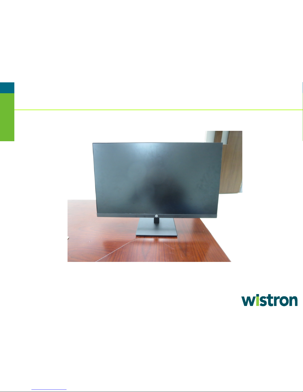
Name/Model: HP Giraffe P274 Display
1.0 Items Requiring Selective Treatment
Quantity of
product
Assemblies (PCA)
power BD interface BD
Batteries, excluding Li-Ion batteries.
All types including standard alkaline, coin or button
style batteries
0
Li-Ion batteries. Include all Li-Ion batteries if more
Battery(ies) are attached to the product by (check all
required tools in the sections 3.1 and 3.2.
0
Mercury-containing components
For example, mercury in lamps, display backlights,
scanner lamps, switches, batteries
0
Liquid Crystal Displays (LCD) with a surface greater
than 100 sq cm
Includes background illuminated displays with gas
discharge lamps panel
1
Cathode Ray Tubes (CRT)
0
Capacitors / condensers (Containing PCB/PCT)
0
Electrolytic Capacitors / Condensers measuring
greater than 2.5 cm in diameter or height
1
External electrical cables and cords
AC power cord , HD cable, HDMI cable, VGA cable
4
Gas Discharge Lamps
0
Plastics containing Brominated Flame Retardants
weighing > 25 grams (not including PCBs or PCAs
0
Product End-of-Life Disassembly Instructions
Product Category: External Options Monitor and Display
Purpose: The document is intended for use by end-of-life recyclers or treatment facilities. It provides the basic instructions for
the disassembly of HPI products to remove components and materials requiring selective treatment, as defined by EU directive
2012/19/EC, Waste Electrical and Electronic Equipment (WEEE).
NOTE: Recyclers should sort plastic materials into resin streams for recycling based on the ISO 11469 plastic marking code on
the plastic part. For any questions on plastic marking, please contact HP’s Sustainability Contact
1.1 Items listed below are classified as requiring selective treatment.
1.2 Enter the quantity of items contained within the product which require selective treatment in the right column, as
applicable.
.
Item Description Notes
Printed Circuit Boards (PCB) or Printed Circuit
than one is provided with the product (such as a
detachable notebook keyboard battery, RTC coin cell,
etc.)
With a surface greater than 10 sq cm
that apply with an “x” inside the “[ ]”):
[ ] screws
[ ] snaps
[ ] adhesive
[ ] other. Explain
NOTE: Add detailed removal procedures including
items
included in
2
EL-MF877-00 Page 1
Template Revision C
Last revalidation date 09-May-2018
HPI instructions for this template are available at EL-MF877-01
Page 2
Item Description Notes
Quantity of
product
already listed as a separate item above)
Components and parts containing toner and ink,
including liquids, semi-liquids (gel/paste) and toner
Include the cartridges, print heads, tubes, vent
chambers, and service stations.
0
Components and waste containing asbestos
0
Components, parts and materials containing
refractory ceramic fibers
0
Components, parts and materials containing
radioactive substances
0
2.0 Tools Required
Tool Description
Tool Size (if
applicable)
Description #1 SCREW DRIVER(PHILLIPS HEAD)
#1
Description #2 SCREW DRIVER(PHILLIPS HEAD)
#2
Description #3 SCREW DRIVER(HEX HEAD)
Description #4 SPANNER
#10
3.0 Product Disassembly Process
items
included in
List the type and size of the tools that would typically be used to disassemble the product to a point where components and
materials requiring selective treatment can be removed.
3.1 List the basic steps that should typically be followed to remove components and materials requiring selective treatment
including the required steps to remove the external enclosure:
1. Remove Cable From Display Head
2. Remove Stand Base From Display Head
3. Remove Rear Cover From Display Head
4. Remove Adhesive From Display Head
5. Remove Bracket From Display Head
6. Remove Middle Frame From Display Head
7. Middle Frame ASSY Disassembly
8. Rear Cover ASSY Disassembly
9. Bracket ASSY Disassembly
10. Stand ASSY Disassembly
11. Base ASSY Disassembly
12. Panel Module Disassembly
3.2 Optional Graphic. If the disassembly process is complex, insert a graphic illustration below to identify the items contained
in the product that require selective treatment (with descriptions and arrows identifying locations).
EL-MF877-00 Page 2
Template Revision C
Last revalidation date 09-May-2018
HPI instructions for this template are available at EL-MF877-01
Page 3
P274 Disassemble Process
Prepare By: Jess Yang
Date : 2018/12/07
Page 4
1.Remove Cable From Display Head
1
1.Remove cable from display head
Page 5
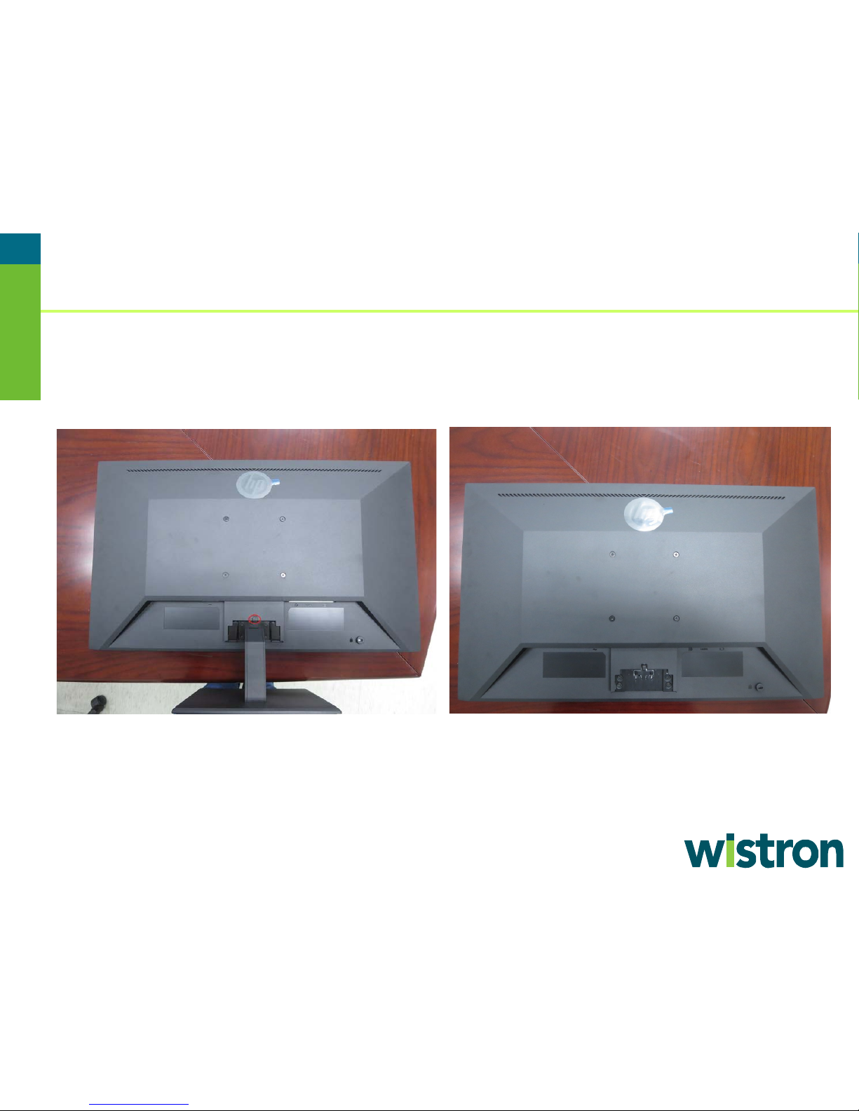
2.Remove Stand Base From Display Head
2
2.Push the red point 3.Remove stand base assembly
Page 6
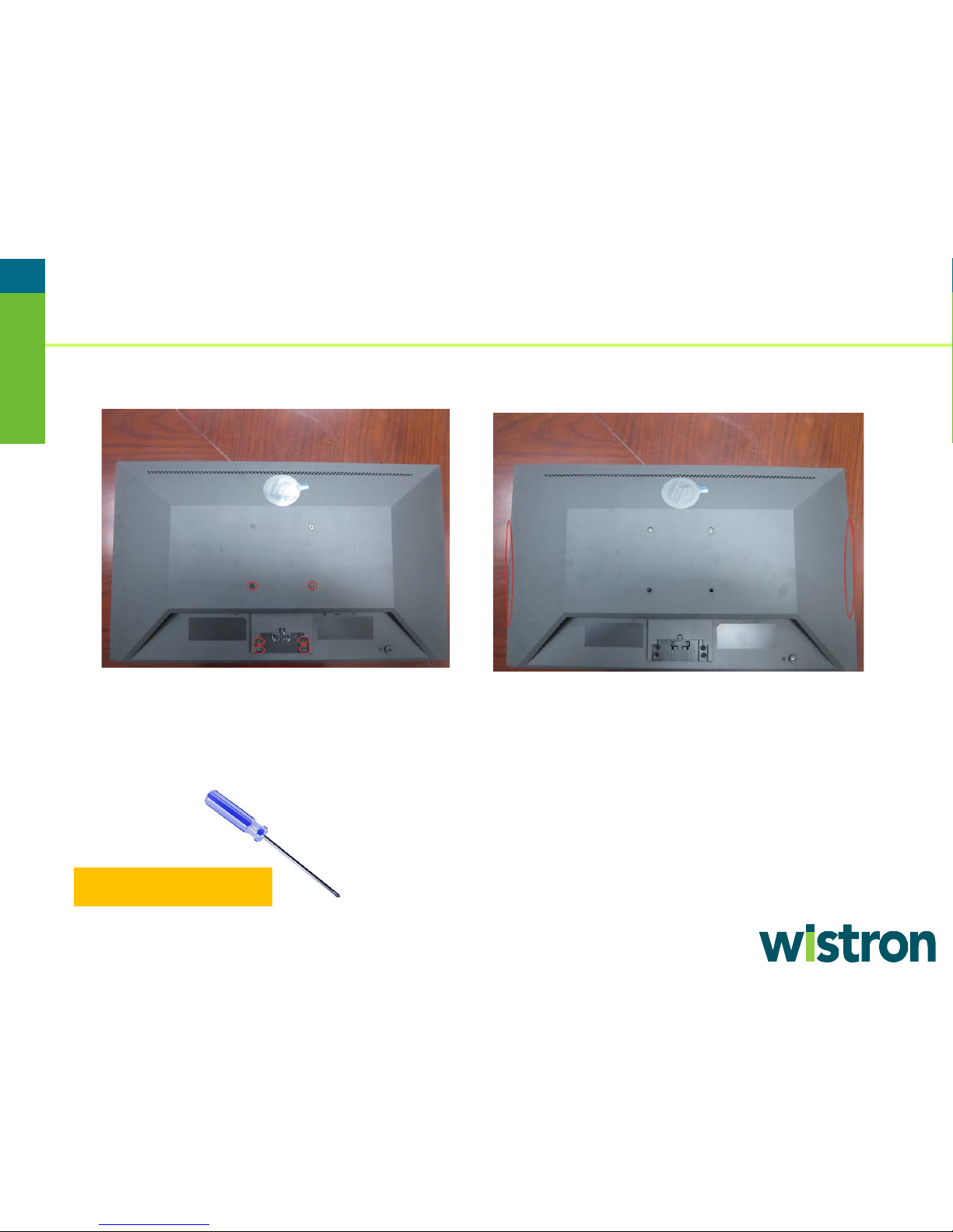
3.Remove Rear Cover From Display Head
3
4.Release the six screws from rear cover
by cross screwdriver
5.Pull up rear cover left and right side
cross screwdriver
Page 7

3.Remove Rear Cover From Display Head
4
7.Remove rear cover
6.Pull the rear cover from the bottom up
Page 8

4.Remove Adhesive From Display Head
5
8.Remove aluminum foil 9.Remove acetate tape
Page 9

5.Remove Bracket From Display Head
6
10. Release the two screws from bracket
by cross screwdriver
11. Overturn bracket and remove all cables
Page 10

6.Remove Middle Frame From Display Head
7
12.Remove bracket assembly and release
the thirteen screws from middle frame
13.Remove middle frame from the top
down
Page 11

7.Middle Frame ASSY Disassembly
8
14.Destroy heat stake then remove OSD
key and lens
Page 12

8.Rear Cover ASSY Disassembly
9
15.Destroy heat stake then remove the
small iron
Page 13

9.Bracket ASSY Disassembly
10
16.Remove the black mylar
17.Release the five screws by cross screwdriver
18.Release the four screws by cross
screwdriver
19.Remove PCB then tear off gasket and
white mylar
Page 14

10.Stand ASSY Disassembly
11
20.Push the release button then remove
the stand
21.Release the four screws by cross
screwdriver
22.Remove hinge from stand 23.Release four screws from hinge
Page 15

10.Stand ASSD Disassembly
12
24.Release the two screws and nut
from hinge by cross screwdriver
25.Remove all part
Page 16

11.Base ASSY Disassembly
13
26.Remove the five rubbers then
release all screws by cross screwdriver
27.Remove the chassis
Page 17

12.Panel Module Disassembly
14
19.Disassemble panel assembly
Page 18

12.Panel Module Disassembly
15
19.Disassemble panel assembly
Page 19

12.Panel Module Disassembly
16
19.Disassemble panel assembly
Page 20

17
Thank You !!!
 Loading...