

Page 1

www.hp.com/go/pcaccessories
hp
wireless LAN
access point
installation guide
P1981A
Page 2

Notice
The information contained in the documents accompanying this product is subject to change without notice.
Hewlett-Packard makes no warranty of any kind with regard to this material, including, but not limited to,
the implied warranties of merchantability and fitness for a particular purpose.
Hewlett-Packard shall not be liable for errors contained herein or for incidental or consequential damages in
connection with the furnishing, performance, or use of this material. Hewlett-Packard assumes no
responsibility for the use or reliability of its software on equipment that is not furnished by Hewlett-Packard.
These documents contain proprietary information that is protected by copyright.
All rights are reserved. No part of these documents may be photocopied, reproduced, or translated to
another language without the prior written consent of Hewlett-Packard Company.
Page 3

English
Introduction . . . . . . . . . . . . . . . . . Chapter 1
Hardware Installation . . . . . . . . . Chapter 2
Software Installation and
Network Settings. . . . . . . . . . . . . Chapter 3
Troubleshooting . . . . . . . . . . . . . Chapter 4
Technical Specifications. . . . . . . Chapter 5
Regulatory Information . . . . . . . Chapter 6
Page 4

Page 5

Chapter 1 - Introduction
This chapter introduces you to your HP Wireless LAN Access Point.
Welcome
The HP Wireless LAN Access Point enables you to create various types of wireless
network applications in your office.
Wireless networking is an ‘out-of-the-box’ mode of operation for the Wireless LAN
Access Point. After powering the device, it will forward the data communication from
one wireless computer to another. You can easily extend your wireless network by
adding more wireless computers.
A wireless network uses radio waves to communicate between wireless computers.
The waves can pass through solid objects, like walls. A data encryption feature is
used to increase the security of your wireless network.
To create a wireless network you will need:
• An HP Wireless LAN Access Point: To provide wireless data communications
between computers, to the Internet, or to a wired Ethernet network
• USB Wireless LAN devices: For each computer you want to connect to the wireless
network.
Supported Operating Systems
The HP Wireless LAN Access Point is compatible with the following operating
systems:
• Windows 95
• Windows 98
• Windows 2000
• Windows NT 4.0
Support
You can find extra documentation for the HP wireless product range on the software
CD-ROM supplied with the Wireless LAN Access Point.
For the latest information on the HP wireless range, access the HP web site at:
www.hp.com/go/bri osupport
www.hp.com/go/vec trasuppor t
www.hp.com/go/kay aksupport
www.hp.com/go/e-p csupport
Kit Contents
Your HP Wireless LAN Access Point kit includes the following items:
• 1 HP Wireless LAN Access Point
•1 HP Wireless LAN Access Point Getting Started guide
•1 Installation Software CD-ROM
• 1 Power adapter
• 1 Telephone cable
• Screws and plugs.
English 1
Page 6

Network Options
There are multiple ways to set up a wireless network: Internet through your phone,
Internet through your cable modem and Wireless to wired network.
• Internet through Your Phone Line
The Wireless LAN Access Point includes a built-in 56K modem that allows you to
share an Internet connection between multiple computers. To use the Wireless
LAN Access Point to access the Internet, you must have a traditional phone line,
and an account with an Internet Service Provider.
• Internet through Your Cable Modem
If you have an account with a cable Internet Service Provider and you have a cable
modem, you can use the Wireless LAN Access Point to connect your wireless
computers to the Internet.
• Wireless to Wired Network
When connected by the Wireless LAN Access Point, the computers of a wired
Ethernet group and the computers of your wireless network can share a printer or
any other network device.
NOTE An RG-11 telephone cable for connecting the Wireless LAN Access Point to your
phone outlet comes with your kit. While HP have tried to ensure that the supplied
cable works in as many countries as possible, you may need to purchase the correct
telephone cable for the country where you are using the Wireless LAN Access Point.
Ethernet cables for connecting your cable modem are not supplied with your HP
Wireless LAN Access Point and must be purchased separately.
Network Scenarios
Before you begin installing your USB Wireless LAN it is important to consider which
kind of wireless network you want to create.
The HP Wireless LAN Access Point allows you to create a variety of wireless
networks. For a detailed description of the possible network scenarios, access the HP
web site at www.hp.com/go/pcaccessories
2 English
Page 7

Chapter 2 - Hardware Installation
This chapter describes how to install a Wireless LAN network.
Before You Start
Before beginning a network installation, read the following information:
CAUTION Once you have supplied po we r to the HP Wir eless LAN Ac cess Po in t, do not cove r the
device or block the airflow to the device with any other objects. Ensure that the device
is not exposed to high temperatures or high levels of humidity.
Placing Your HP Wireless LAN Access Point
Before beginning network installation, it is recommended that you follow these
guidelines:
• Position the device as centrally as possible to the computers that will be in the
wireless network
• Place the device next to a power outlet that can be easily reached by the power
cord
• If you are planning to connect your Wireless LAN Access Point to a phone line,
ensure that the phone outlet is close to the device
• If you are planning to connect external equipment to the Ethernet port of your
Wireless LAN Access Point, ensure that the equipment is close to the device.
Cleaning Your HP Wireless LAN Access Point
To maintain the functionality of your HP Wireless LAN Access Point, always keep the
device as clean as possible. The device can be cleaned with a soft tissue. Avoid the
use of abrasive cleaning materials or aggressive liquids such as alcohol.
English 3
Page 8

Removing the Rear Cover
When making cable connections to the HP Wireless LAN Access Point, first remove
the rear cover from the device. To remove the cover:
1 Take the front of the device in
one hand and the rear cover in
your other hand.
2 Press in the release latches on
both sides of the rear cover.
3 Pull the unit away from the
rear cover until the release
latches come out of the rear
cover.
4 Lift up the device to
disconnect it from the rear
cover.
release catches
rear cover unit
NOTE Write down the ID code of your HP Wireless LAN Access Point. The code later can
be found on a small label at the rear of the device. You will need this ID code if you
want to make any changes to the settings of your network.
4 English
Page 9
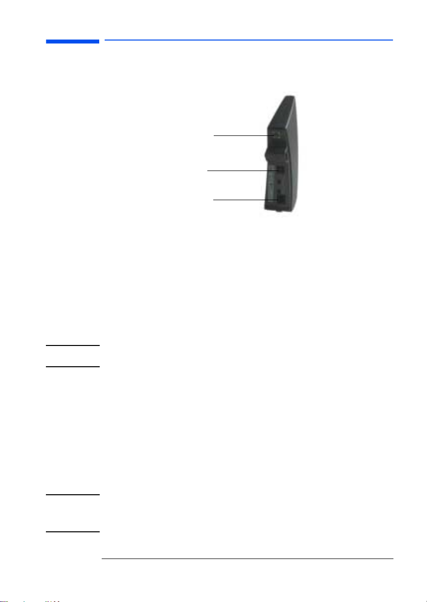
Connecting the Cables
After removing the rear cover, you will see three cables sockets at the rear of the
device.
telephone socket
power socket
Ethernet socket
Connecting the Power Adapter Cable
To connect the power cable, plug the connector at the end of the power adapter
cable into the power socket of the HP Wireless LAN Access Point.
Connecting a Telephone Cable for Internet through Your Phone
Line
If you want to have Internet via your phone line you can use the telephone cable that
came with your kit. To connect a telephone cable:
1 Plug one of the connectors on the telephone cable into the telephone socket of
the HP Wireless LAN Access Point.
2 Plug the other connector on the telephone cable to your phone outlet.
NOTE Depending on local standards, you may need a special adapter plug to connect the
NOTE To connect the HP Wireless LAN Access Point to an Ethernet network, use a
telephone cable to your outlet.
If you want Internet via your cable modem, use a 10BaseT crossover cable to make a
direct connection between the HP Wireless LAN Access Point and your cable
modem.
Connecting an Ethernet Cable for Internet through Your Cable
Modem
If you want Internet via your cable modem, use an Ethernet cable and a 10BaseT
crossover cable to make a direct connection between the HP Wireless LAN Access
Point and your cable modem.
To connect an Ethernet cable:
1 Plug one of the Ethernet cable connectors into the Ethernet sockets of the HP
Wireless LAN Access Point.
2 Plug the other Ethernet cable connector into your cable modem.
standard 10BaseT cable to connect your HP Wireless LAN Access Point to the
Ethernet hub and a 10BaseT crossover cable for making a direct connection between
the HP Wireless LAN Access Point and a single Ethernet device (not via a hub).
English 5
Page 10

Wall Mounting the Wireless LAN Access Point
The information in this section is only applicable if you want to mount the HP
Wireless LAN Access Point to the wall.
To mount the Wireless LAN Access Point to the wall:
1 Pierce the three rear screw
holes with a sharp pointed
object.
2 Decide where and how you
want to place the HP Wireless
LAN Access Point (you may
consider mounting the device
upside-down on high spots, to
be able to see the LEDs).
3 Place the rear cover against
the wall, and put three marks
on the wall to indicate the
screw positions.
4 Use the screws and the plugs
that came with your kit to fix
the rear cover to the wall.
rear cover
screw holes
Attaching the Rear Cover
Once the cables have been successfully connected and the placement decided, you
can attach the rear cover to the Wireless LAN Access Point. To attach the rear cover:
1 Bring the device close to the rear cover.
2 Guide the cable(s) coming from the device through the cable entrance of the rear
cover.
3 Insert the small hook at the bottom of the unit in the rear cover slot.
4 Turn the un it to th e rea r cov er. Pr es s in bo th re leas e l atche s to in sert t he m in the
rear cover.
5 Push the rear cover against the unit until the release latches lock into place.
If you want to place the HP Wireless LAN Access Point on a flat surface you have to
guide the cable(s) through the cable entrance at the back of the rear cover. By doing
this, the device can stand upright.
6 English
Page 11
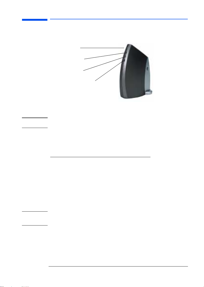
Powering the HP Wireless LAN Access Point
There is no On/Off switch on the HP Wireless LAN Access Point. This is because the
device uses very little power.
Power LED
Wireless LED
Ethernet LED
Telephone/Modem LED
To power-up the device:
1 Plug the power adapter into a power outlet to start the power-up process.
CAUTION After applying power to the Wireless LAN Access Point, do not cover the device or
block the airflow to the device with any other objects.
2 Monitor the LED activity on the device. The LEDs will change color between
Yellow, Red and Green. When finished, the Wireless LAN Access Point shows
LED activity as listed in the table below.
Name Color/Activity Description
Power Steady Green Power enabled
Wireless Off, or Flashing
Ethernet Off, or Flashing
Telephone/
Modem
NOTE If the HP Wireless LAN Access Point does not switch to normal operation within one
minute, try to solve the problem with the troubleshooting information in the online
manual on the CD-ROM.
Green or Red
Green or Red
Off, or Flashing
Green or Red
Wireless activity
Ethernet activity
Modem activity
English 7
Page 12

Page 13

Chapter 3 - Software Installation and
Network Settings
This chapt er describes how to install the Wireless LAN Access Poin t software and set
new settings for your network.
Installing Software
Choosing Your Computer
Decide on which of your wireless computers you are going to install the software.
This computer will be your administrative station and, once the software is installed,
it will allow you to change the settings for your wireless network. You can install the
software on any computer, as long as it has:
• A USB Wireless LAN connected to your PC
• At least 5MB of free hard disk space
• Microsoft Windows 95, Windows 98 or Windows 2000
• If you are planning to connect external equipment to the Ethernet port of your
Wireless LAN Access Point, ensure that the equipment is close to the device.
NOTE Installing the software on more than one computer allows you to change the network
NOTE If your computer has Autorun enabled, the CD-ROM will start automatically. To
settings from more locations. However, it is recommended that you do not install the
software on all the computers in your wireless network as it increases the chances
of the settings being changed regularly by all members of the wireless network.
Performing the Installation
Follow these steps to install the software on your computer:
1 Insert the CD-ROM into your CD-drive.
2 Click the Start button on the Windows taskbar.
3 Select Run.
4 Click the Browse button to open the Browse window.
5 Double click on the icon for your CD-ROM drive to see the contents of the CD-
ROM.
6 Open the Software directory, then select RG
7 Double-click the Setup.exe file.
8 An install program will start. Follow the instructions on your screen to install the
software on your computer.
install the software select Install Software and then RG Setup tool.
English 9
Page 14

Changing the Settings
Preparation
Before attempting to change the settings, follow these steps:
1 Make sure that all necessary cables are connected to the Wireless LAN Access
Point.
2 Make sure that your Wireless LAN Access Point is powered and is operating
normally.
3 Make sure that the Wireless USB LAN settings on your wireless computer are
correct.
Running the Utility
Follow these steps to run the setup utility and change the network settings:
1 Click the Start button on the Windows taskbar.
2 Select Programs and then Orinoco.
3 Select the RG Setup Utility.
4 Change the settings when required or desired.
NOTE The Wireless LAN Access Point and all USB Wireless LANs in your wireless network,
must have the same Encryption Key in order for the devices to transmit and receive
readable data. This means that if you change the Encryption Key for the Wireless
LAN Access Point, you must update the Encryption Key in the settings on every
wireless computer in your wireless network.
10 English
Page 15

Chapter 4 - Troubleshooting
This chapter demonstrates how to solve any problems with your Wireless LAN
Access Point device.
HP Support
You can get help solving problems with HP accessories from the following HP
support Web sites:
www.hp.com/go/briosupport
www.hp.com/go/vectrasupport
www.hp.com/go/kayaksupport
www.hp.com/go/e-pcsupport
Reset and Reload Buttons
The Reload button
Pressing the Reload button will return the Access Point to its initial configuration. In
this state the encryption will be disabled and you will be able to access the Access
Point without the Encryption Key.
The Reset button
Pressing the Reset button will reset the Access Point if it has become frozen.
Special Modes
The Wireless LAN Access Point has several special modes.
Occurrence Action
After supplying power to the Access Point The Access Point will start automatically returns to
normal operation within 1 minute
After finishing the RG Setup utility The network settings will be sent from your
After pressing the Reset button The Access Point will restart and automatically
After pressing the Reload button The Access Point will restart and automatically
computer to the Access Point. The Access Point will
then restart and automatically return to normal
operation within 1 minute
return to normal operation within 1 minute
return to normal operation
English 11
Page 16

Troubleshooting Scenarios
Use the following scenarios to solve problems:
Scenario 1
I can not make a connection between my computer(s), or to the Internet.
1 If the Access Point is in one of the special modes, wait for approximately one
minute to allow the Access Point to return to normal operation. Perform a reset
if the Access Point does not automatically return from a special mode to normal
operation within approximately one minute.
2 Make sure you have set the right values for the following USB Wireless LAN
parameters on your wireless computers:
•Network Name: Enter the Access Point ID
•Encryption Key: Enter the last 5 digits of the Access Point ID.
NOTE Note: The Access Point and all USB Wireless LANs in the wireless network must have
the same Encryption Key in order for the devices to transmit and receive readable
data. This means that if you changed the Encryption Key with the RG Setup Utility,
you have to update the Encryption Key in the USB Wireless LAN settings on every
wireless PCs in your network.
3 Us e the Ac c ess Po int LE D tab l e or th e Acce s s Poin t Tro u bles hoot ing ta b le to fi nd
the problem.
Scenario 2
My network worked fine, but after running the RG Setup utility I can not make a
connection between my computer(s), or to the Internet.
1 Make sure to set the right value for the Access Point ID in the RG Setup utility.
2 The Access Point and all USB Wireless LANs in your wireless network, must have
the same Encryption Key in order for the devices to transmit and receive
readable data. This means that if you changed the Encryption Key for the Access
Point in the RG Setup utility, you have to update the Encryption Key on every
wireless computer in your network.
3 Use the Access Point LEDs and the Access Point Troubleshooting table to find
the problem.
12 English
Page 17

Scenario 3
I changed the Encryption Key of my Wireless LAN Access Point with the RG Set-up
utility. Now I want to update the Encryption Key on my wireless computers, but have
forgotten the 5 character Encryption Key code.
1 If you change the Encryption Key on the Access Point, you have to update the
Encryption Key on every wireless computer in your network.The Access Point
and all wireless computers in your network, must have the same Encryption Key
in order for the devices to transmit and receive readable data.
2 If you change the Encryption Key, you are advised to write it down and keep it in
a safe place. If you forget the key, you will not be able to update the Encryption
Key in the USB Wire less LAN settings on your wireless computers. As a result of
that you will also no t be abl e to cha nge the Access Point Encr yp ti on Key wi th the
setup utility.
3 There is no other way to solve the problem than to perform a 'reload' on the
Access Point. The reload will change the Encryption Key to the default value.
4 After the reload you can run the Access Point RG Set-up utility again, and change
the default Encryption Key to a new value. Do not forget to update the
Encryption Key in the USB Wireless LAN settings on your wireless computers.
NOTE Whenever you change the Encryption Key, you are advised to write it down and keep
it in a safe place.
LED Activity
Power
LED
Off Off Off Off No power Check power cable and power supply
Off On/Flashing On/Flashing On/Flashing Broken Return Access Point to dealer
Green Off Off/Flashing
Green Flashing
Green Off On/Flashing/
Green Off Flashing Red On/Flashing/
Green Flashing
Green On/Off On/Off Flashing Red Impossible to send data to the
Red/Orange Red/Orange Red/Orange Red/Orange Access Point broken Return to HP dealer
Red Red Red Red Booting up or crashed If Access Point has just been powered
Wireless
LED
Red
On/Off
Ethernet
LED
Green
On/Flashing/
Off
Off
Flashing
On/Off
Modem
LED
Off/Flashing
Green
On/Flashing/
Off
On/Flashing/
Off
Off
Off No data received from phone
Access Point Status Solution
No data received from
wireless network
Impossible to send data to
wireless network
No data received from the
Ethernet/wireless network
Impossible to send data to
Ethernet/wireless network
line
phoneline
1. Connect PCs with USB Wireless LAN
2. Reduce distance between USB
Wireless LAN
1. Connect PCs with USB Wireless LAN
2. Reduce distance between USB
Wireless LAN
3. If in special mode, wait 1 minute
1. If in special mode, wait 1 minute
2. Check Ethernet cable is working
1. If in special mode, wait 1 minute
2. Check Ethernet cable is working
1. If in special mode, wait 1 minute
2. Try to set-up an Internet connection
3. Make sure phoneline works correctly
1. If in special mode, wait 1 minute
2. Make sure the phoneline works
correctly
up it is booting up no action should be
taken. If LEDs remain red for a
prolonged period the Access Point has
crashed and should be reset.
English 13
Page 18

Support Part Numbers
Product Support Part Number Description
P1981A US #ABA: US Wireless LAN Access
Point
P1981A EUR #ABB: EUR Wireless LAN Access
Point
P1981A UK #ABU: UK Wireless LAN Access
Point
P1981A Australia #ABG: Australia Wireless LAN
Access Point
P1981-63001 US Wireless LAN Access
Point
P1981-63002 EUR Wireless LAN Access
Point
P1981-63003 UK Wireless LAN Access
Point
P1981-63004 Australia Wireless LAN
Access Point
14 English
Page 19

Chapter 5 - Technical Information
Technical Specifications
Wireless Data Rate up to 11 Mbps
WLAN Standard IEEE 802.11 (standard for High speed and Wi-Fi certified WLAN)
Bit Error Rate better than 10
Frequency band / Channels 2.4 Ghz.
Selectable channels:
• Channel A: 2412 MHz
• Channel B: 2427 MHz
• Channel C: 2442 MHz
• Channel D: 2457 MHz
Input Voltage 7 to 15V DC
Modem 56k, V.90, RJ-11 (female)
Ethernet 10Base-T, RJ-45
Wireless HP Wireless USB LAN
Operating Temperature 0 to +40
Storage Temperature -10 to +50
-5
o
C
o
C
Humidity max. 95% (no condensation allowed)
Baromatic Pressure 740 to 1050 hPa
Dimensions (HxWxL) 208 mm (H) x 52 mm (W) x155 mm (L)
Weight 350g
English 15
Page 20

Radio Specifications
Radio Output Power 15 dbm (nominal)
Spreading 11-chip Barker Sequence
Wireless Data Rate
Environment 11 Mb/s 5.5 Mb/s 2 Mb/s 1 Mb/s
Range if open
Range if semi-open
Range if closed
1
3
2
160 m
(525 ft.)
50 m
(165 ft.)
25 m
(80 ft.)
270 m
(885 ft.)
70 m
(230 ft.)
35 m
(115 ft.)
400 m
(1300 ft.)
90 m
(300 ft.)
40 m
(130 ft.)
550 m
(1750 ft.)
115 m
(375 ft.)
50 m
(165 ft.)
Modulation technique DSSS
Receiver Sensitivity
(for BER =10
Delay Spread
(at FER of <1%)
1. In Open environments, antennae can “see” each other, i.e. there are no physical obstructions between them.
2. In Semi-open environments, work space is divided by shoulder-height, hollow wall elements, antennas are at
desktop level.
3. Closed environments, work space is separated by floor-to-ceiling brick walls.
-5
)
CCK
-82 dBm -87 dBm -91 dBM -94 dBm
65 ns 225 ns 400 ns 500 ns
DSSS
CCK
DSSS
DQPSK
DSSS
DBPSK
NOTE The range values provide a rule of thumb and may vary according to the actual
conditions at the location where the product will be installed. The range of the
wireless signal is related to Transmit Rate of the wireless communication. The range
of your wireless devices can be affected when the antennae are placed near metal
surfaces and solid high-density materials. Range is also impacted due to “obstacles”
in the signal path of the radio that may either absorb or reflect the radio signal.
16 English
Page 21

Power Adpater Specifications
Types AU, UK, US, JP, EU
Dimensions (HxMxL) 78 mm (H) x48 mm (W) x75 mm (L)
Input voltage 100 to 240V +/- 10%
Frequency 47 to 63 Hz
Operating temperature 0 to +50
Storage temperature -20 to+85
Humidity 20 to 90%
o
C
o
C
English 17
Page 22

Page 23

Chapter 6 - Regulatory Information
Part 15 FCC Compliance Statement
This device complies with Part 15 of FCC rules. Operation is subject to the following
two conditions:
1. This device may not cause harmful interference, and
2. This device must accept any interference received, including interference that
may cause undesired operation.
Operation environment
For Home and Office use
Notice
This equipment has been tested and found to comply with the limits of Class B digital
device, pursuant to Part 15 of the FCC Rules. These limits are designed to provide
reasonable protection against harmful interference in a residential installation. This
equipment generates, uses and can radiate radio frequency energy and, if not
installed and used in accordance with the instructions, may cause harmful
interference to radio communications. However, there is no guarantee that
interference will not occur in a particular installation, if this equipment does cause
harmful interference radio or television reception, which can be determined by
turning the equipment off and on, the user is encouraged to try to correct the
interference by one or more of the following measures:
! Reorient or relocate the receiving antenna.
! Increase the separation between the equipment and receiver.
! Connect the equipment into an outlet on a circuit different from that to which
the receiver is connected.
! Consult the dealer or an experienced radio/TV technician for help.
Caution
To comply with the limits for class B digital device according to Part 15 of FCC Rules,
this device must be installed in computer equipment certified to comply with the
Class B limits. All cables used to connect the computers and peripherals must be
shielded and grounded. Operation with non-certified/Shielded cables may result in
radio/TV interference.
Modification
Any modification not expressly approved by the manufacturer of this device could
void the user's authority to operate the device.
PART 68 FCC Compliance Statement
This equipment complies with Part 68 of the FCC Rules. A label is attached to this
equipment that contains, among other information, the FCC registration number and
ringer equivalence number (REN) for this equipment. If requested, this information
must be provided to the telephone company.
An FCC compliant telephone cord and modular plug is provided with this equipment.
This equipment is designed to be connected to the telephone network or premises wiring using a compatible modular jack which is FCC part 68 compliant. Connection to the
telephone network should be made by using standard modular telephone jack type
RJ11.
The REN is useful to determine the qua ntity of devices that may be connected to the
telephone line and still have all of those devices ring when your telephone number is
called. In most, but not all areas, the sum of the RENs should not exceed five (5.0).
To be certain of the number of devices that may be connected to the line, as deter-
English 19
Page 24

mined by the total RENs, contact the telephone company to determine the maximum
REN for the calling area.
If this equipment causes harm to the telephone network, the telephone company
may discontinue your service temporarily. If advance notice is not practical, the telephone company will notify the customer as soon as possible. Also, you will be advised
of your right to file a complaint with the FCC if you believe it is necessary.
The telephone company may make changes in its facilities, equipment, operations, or
procedures that could affect the operation of the equipment. If this happens, the
telephone company will provide advance notice in order for you to make the necessary modifications in order to maintain uninterrupted service.
In the event this equipment should fail to operate properly, disconnect the unit from
the telephone line. Try using another FCC approved telephone in the same telephone jack. If the trouble persists, call the telephone company repair service bureau.
If the trouble does not persist and appear s to be with this unit, disconnect the unit
from the telephone line and discontinue use of the unit until it is repaired. Please
note that the telephone company may ask that you disconnect the equipment from
the telephone network until the problem has been corrected or until you are sure
that the equipment is not malfunctioning.
The user must use the accessories and cables supplied by the manufacturer to get
optimum performance from the product.
No repairs may be done by the customer.
If trouble is experienced with this equipment, please contact your authorized
support provider for repair and warranty information. If the trouble is causing harm
to the telephone network, the telephone company may request you remove the
equipment from the network until the problem is resolved.
This equipment cannot be used on telephone company provided coin service.
Connection to Party Line Service is subject to state tariffs.
When programming and/or making test calls to emergency numbers:
! Remain on the line and briefly explain to the dispatcher the reason for the call.
! Perform such activities in the off-peak hours such as early morning or late
evenings.
The Telephone Consumer Protection Act of 1991 makes it unlawful for any person to
use a computer or other electronic device to send any message via a telephone facsimile machine unless such message clearly contains, in a margin at the top or bottom of each transmitted page or on the first page of the transmission, the date and
time it is sent and an identification of the business, other entity, or individual sending
the message and the telephone number of the sending machine of such business,
other entity, or individual.
In order to program this information into your facsimile, refer to your communications software user manual.
Industry Canada Information
The Industry of Canada label identifies certified equipment. This certification means
that the equipment meets the telecommunications network prospective, operational
and safety requirements as described in the appropriate Terminal Equipment
Technical Requirements document(s). The department does not guarantee the
equipment will operate to the user's satisfaction.
Before installing this equipment, make sure you are permitted to connect it to the
facilities of the local Telecommunications Company. You must install the equipment
using an acceptable method of connection. In some cases you may also extend the
company's inside wiring for single line individual service by means of certified
connector assembly (telephone extension cord). You should be aware, however, that
20 English
Page 25

compliance with the above conditions may not prevent degradation of service in
some situations.
Repairs to certified equipment should be made by an authorized Canadian
maintenance facility designed by the supplier. Any repairs or alterations made by a
user to this equipment or equipment malfunctions, may give the telephone
communications company cause to request the user to disconnect the equipment.
For your own protection, make sure that the electrical ground connections of the
power utility, telephone lines and internal metallic water pipes systems, if present,
are connected together. This precaution may be particularly important in rural areas.
Caution: Do not attempt to make electrical ground connections yourself, contact the
appropriate electric inspection authority or an electrician.
To prevent radio interferance to the licensed service, this device is intended to be
operated indoors and away from windows to provide maximum sheilding. Equipment
that is installed outdoors is subject licensing.
Notice: The Ringer Equivalence Number (REN) assigned to each terminal device
provides an indication of the maximum number of terminals allowed to be connected
to a telephone interface. The termination on an interface may consist of any
combination of devices subject only to the requirement that the sum of the Ringer
Equivalence Numbers of all devices does not exceed 5.
EMC Notice: This class A/B digital apparatus complies with Canadian ICES-003
English 21
Page 26

PAN European Regulatory Note
The equipment has been approved under RTTE-Directive. For such product, the following statement is required:
“This equipment has been designed to work with main European countries. Network
compatibility is dependent on internal software settings. Contact your vendor if it is
necessary to use the equipment on a different telephone network or for further product support contact your support provider on the phone numbers provided in the
support warranty documentation provided with the PC.
This equipment has been approved in accordance with Council Decision 98/482/EC
for Pan European single terminal connection to the Public Switched Telephone Network (PSTN). However, due to differences between individual PSTNs provided in
different countries the approval does not, of itself, give an unconditional assurance of
successful operation on every PSTN network termination point.
In the event of problems, you should contact your equipment supplier in the first
instance.
"Dieses Geraet wurde gemaess der Entscheidung 98/482/EG des Rates europaweit
zur Anschaltung als einzelne Endeinrichtung an das oeffentliche Fernsprechnetz
zugelassen. Aufgrund der zwischen den oeffentlichen Fernsprechnetzen verschiedener Staaten bestehenden Unterschiede Stellt diese Zulassung an sich jedoch
keine unbedingte Gewaehr fuer einen erfolgreichen Betrieb des Geraets an jedem
Netzabschlusspunkt dar.
Falls beim Betrieb Probleme auftreten, sollten Sie sich zunaechst an ihren Fachhaendler wenden."
"Cet équipement a reçu l'agrément, conformément à la décision 98/482/CE du Conseil, concernant la connexion paneuropéenne de terminal unique aux Réseaux Téléphoniques Publics Commutés (RTPC). Toutefois, comme il existe des différences
d'un pays à l'autre entre les RTPC, l'agrément en soi ne constitue pas une garantie
absolue de fonctionnement optimal à chaque point de terminaison du réseau RTPC.
En cas de problème, vous devez contacter en premier lieu votre fournisseur."
"La presente apparecchiatura terminale è stata approvata in conformità della decione
98/482/CE del Consigho per la connessione panaeuropea come terminale singolo ad
una reteanalogica PSTN. A causa delle differenze tra le reti dei differenti paesi,
l'approvazione non garantisce però di per sé il funzionamento coretto in tutti punti di
terminazione di rete PSTN.
In caso di problemi contattare in primo luogo il fornitore del prodotto."
"Este equipo ha sido homologado de conformidad con la Decisión 98/482/CE del Consejo para la conexión panaeuropea de un terminal simple a la red telefónica pública
commutada (RTPC). No obstante, a la vista de la diferencias que existen entre las
RTPC que se ofrecen en diferentes países, la homologación no constituye por si sola
una garantia in condicional de funcionamiento satisfactorio en todos los puntos de
terminación de la red de una RTPC.
En caso de surgir algún problema, procede ponerse en contacto en primer lugar el
proveedor de equipo."
"Dit apparaat is goedgekeurd volgens Beschikking 98/482/EG van de Raad voor de
pan-europese aansluiting van enkelvoudige eindapparatuur op het openbare
geschakelde telefoonnetwerk (PSTN). Gezien de verschillen tussen de individuele
PSTN's in de verschillende landen, biedt deze goedkeuring op zichzelf geen onvoorwaardelijke garantie voor een succesvolle werking op elk PSTN-netwerkaansluit-
22 English
Page 27

punt.
Neem bij problemen in eerste instantie contact op met de leverancier van het apparaat."
Network Compatibility Declaration
This product is designed to interwork with the Public Switched Telecommunication
Networks in UK, Ireland, Netherlands, Sweden, Denmark, Finland, Switzerland, Luxembourg, Belgium, France, Germany, Spain, Portugal, Iceland, Greece, Italy, Norway
and Austria.
English 23
Page 28

Notice for Japan
NEW ZEALAND TELECOM WARNINGS
General
“The grant of a Telepermit for any item of terminal equipment indicates only that
Telecom has accepted that the item complies with minimum conditions for
connection to its network. It indicates no endorsement of the product by Telecom,
nor does it provide any sort of warranty. Above all, it provides no assurance that any
item will work correctly in all respects with another item of Telepermited equipment
of a different make or model, nor does it imply that any product is compatible with all
of Telecom’s network services.”
“This equipment does not fully meet Telecom’s impedance requirements.
Performance limitations may occur when used in conjunction with some parts of the
network. Telecom will accept no responsibility should difficulties arise in such
circumstances.”
“This equipment shall not be set up to make automatic calls to the Telecom ‘111’
Emergency Service.”
“If a charge for local calls is unacceptable, the ‘Dial’ button should NOT be used for
local calls. Only the 7-digits of the local number should be dialled from your
telephone. DO NOT dial the area code digit or the ‘0’ prefix.”
“This equipment may not provide for the effective hand-over of a call to another
device connected to the same line.”
Important Notice
“Under power failure conditions, this telephone may not operate. Please ensure that
a separate telephone, not dependent on local power, is available for emergency use.”
“Some parameters required for compliance with Telecom’s Telepermit requirements
are dependent on the equipment (PC) associated with this device. The associated
equipment shall be set to operate within the following limits for compliance with
Telecom’s Specification:-
24 English
Page 29

1
a Th ere shall be no mo re tha n 10 call attempts to the same number within any
30 minute period for any single manual call initiation, and
b The equipment shall go on-hook for a period of not less than 30 seconds
between the end of one attempt and the beginning of the next attempt.
2 Where automatic calls are made to different numbers, the equipment shall go on-
line for a period of not less than 5 seconds between the end of one attempt and
the beginning of the next attempt.
3 The equipment shall be set to ensure that calls are answered between 3 and 30
seconds of receipt of ringing.”
“All persons using this device for recording telephone conversations shall comply
with the New Zealand law. This requires that at least one party to the conversation is
to be aware that it is being recorded. In addition, the Principles enumerated in the
Privacy Act 1993 shall be complied with in respect to the nature of the personal
information collected, the purpose for its collection, how it is used and what is
disclosed to any other party.”
English 25
Page 30

Hardware Warranty
This HP accessory is covered by a limited hardware warranty for a period of one year
from the date of purchase by the original end-user. The type of service provided is
return to an HP or repair-authorized reseller service-center.
At Hewlett-Packard's discretion, a defective accessory will be repaired or replaced
by a new unit, either of the same type or of an equivalent model.
If this accessory is purchased and used together with an HP Brio, HP e-pc, HP Vectra
personal computer or an HP Kayak PC Workstation, it will be covered by the
warranty of this computer or workstation, under the same conditions of service and
duration.
Please, refer to the warranty statement provided with your HP personal computer or
PC workstation for warranty limitations, customer responsibilities and other terms
and conditions.
FOR CONSUMER TRANSACTIONS IN AUSTRALIA AND NEW ZEALAND: THE
WARRANTY TERMS CONTAINED IN THIS STATEMENT, EXCEPT TO THE
EXTENT LAWFULLY PERMITTED, DO NOT EXCLUDE, RESTRICT OR MODIFY
AND ARE IN ADDITION TO THE MANDATORY STATUTORY RIGHTS APPLICABLE
TO THE SALE OF THIS PRODUCT TO YOU.
HP Software Warranty
THIS WARRANTY STATEMENT TAKES PRECEDENCE OVER ANY OTHER
SOFTWARE WARRANTY STATEMENT INCLUDED WITH THIS PRODUCT
Ninety-Day Limited Software Warranty
HP warrants for a period of NINETY (90) DAYS from the date of the purchase that
the software product will execute its programming instructions when all files are
properly installed. HP does not warrant that the software will be uninterrupted or
error free. HP does not warrant to the performance of usefulness of any software
provided with your computer product. Unless otherwise expressly provided by HP, it
is your own responsibility to obtain the latest version of any software and support
directly from the software owner or authorized distributor. In the event that this
software product fails to execute its programming instructions during the warranty
period, Customer’s remedy shall be a refund or repair. Should HP be unable to
replace the media within a reasonable amount of time, Customer’s alternate remedy
shall be a refund of the purchase price upon return of the product and all copies
Removable Media (If supplied)
HP warrants the removable media, if supplied, upon which this product is recorded
to be free from defects in materials and workmanship under normal use for a period
of NINETY (90) DAYS from the date of purchase. In the event the media proves to be
defective during the warranty period, Customer’s remedy shall be to return the
media to HP for replacement. Should HP be unable to replace the media within a
reasonable amount of time, Customer’s alternate remedy shall be a refund of the
purchase price upon return of the product and destruction of all other nonremovable
media copies of the software product.
Notice of Warranty Claims
Customer must notify HP in writing of any warranty claim not later than thirty (30)
days after the expiration of the warranty period.
The above warranty shall not apply to defects resulting from: misuse; unauthorized
modification; operation or storage outside the environmental specifications for the
product; in-transit damage; improper maintenance; or defects resulting from use of
non-HP software, accessories, media, supplies, consumables, or such items not
designed for use with the product.
26 English
Page 31

HP MAKES NO OTHER EXPRESS WARRANTY, WHETHER WRITTEN OR ORAL
WITH RESPECT TO THIS PRODUCT. ANY IMPLIED WARRANTY OF
MERCHANTABILITY OR FITNESS FOR A PARTICULAR PURPOSE IS LIMITED TO
THE DURATION OF THE EXPRESS WARRANTY SET FORTH ABOVE. SOME
STATES OR PROVINCES DO NOT ALLOW LIMITATIONS ON HOW LONG AN
IMPLIED WARRANTY LASTS, SO THE ABOVE LIMITATIONS OR EXCLUSION MAY
NOT APPLY TO YOU.
Limitation of Liability and Remedies
THE REMEDIES PROVIDED ABOVE ARE CUSTOMER’S SOLE AND EXCLUSIVE
REMEDIES. IN NO EVENT SHALL HP BE LIABLE FOR ANY DIRECT, INDIRECT,
SPECIAL, INCIDENTAL OR CONSEQUENTIAL DAMAGES (INCLUDING LOST
PROFIT) WHETHER BASED ON WARRANTY, CONTRACT, TORT OR ANY OTHER
LEGAL THEORY. Some states or provinces do not allow the exclusion or limitation of
incidental or consequential damages, so the above limitation or exclusion may not
apply to you.
FOR CONSUMER TRANSACTIONS IN AUSTRALIA AND NEW ZEALAND: THE
WARRANTY TERMS CONTAINED IN THIS STATEMENT, EXCEPT TO THE
EXTENT LAWFULLY PERMITTED, DO NOT EXCLUDE, RESTRICT OR MODIFY
AND ARE IN ADDITION TO THE MANDATORY STATUTORY RIGHTS APPLICABLE
TO THE SALE OF THIS PRODUCT TO YOU.
HP Software License Agreement
CAREFULLY READ THIS LICENSE AGREEMENT BEFORE PROCEEDING TO
OPERATE THE HP ACCESSORY. RIGHTS IN THE SOFTWARE ARE OFFERED
ONLY ON THE CONDITION THAT THE CUSTOMER AGREES TO ALL TERMS AND
CONDITIONS OF THIS LICENSE AGREEMENT. PROCEEDING TO INSTALLING
AND USING THE ACCESSORY INDICATES YOUR ACCEPTANCE OF THESE
TERMS AND CONDITIONS. IF YOU DO NOT AGREE TO THE LICENSE
AGREEMENT, YOU MUST NOW DESTROY ANY MASTER DISKETTES OR CDROMS, OR RETURN THE COMPLETE ACCESSORY AND SOFTWARE FOR A FULL
REFUND.
UNLESS OTHERWISE STATED BELOW, THIS HP SOFTWARE PRODUCT LICENSE
AGREE MENT SHALL GOVER N THE USE OF ALL SOFTWARE THAT IS PROVIDED
TO YOU, THE CUSTOMER, AS PART OF THE HP ACCESSORY. IT SHALL
SUPERSEDE ANY NON-HP SOFTWARE LICENSE TERMS THAT MAY BE FOUND
ON-LINE, OR IN ANY DOCUMENTATION OR OTHER MATERIALS CONTAINED IN
THE ACCESSORY PRODUCT PACKAGING.
Note: Operating System Software by Microsoft is licensed to you under the Microsoft
End User License Agreement (EULA) contained in the Microsoft documentation.
The following License Terms govern the use of the software:
USE. Customer may use the software on any one computer. Customer may not
network the software or otherwise use it on more than one computer. Customer may
not reverse assemble or decompile the software unless authorized by law.
COPIES AND ADAPTATIONS. Customer may make copies or adaptations of the
software (a) for archival purposes or (b) when copying or adaptation is an essential
step in the use of the software with a computer so long as the copies and adaptations
are used in no other manner.
OWNERSHIP. Customer agrees that he/she does not have any title or ownership of
the software, other than ownership of the physical media. Customer acknowledges
and agrees that the software is copyrighted and protected under the copyright laws.
Customer acknowledges and agrees that the software may have been developed by a
third party software supplier named in the copyright notices included with the
software, who shall be authorized to hold the Customer responsible for any copyright
infringement or violation of this Agreement.
English 27
Page 32

TRANSFER OF RIGHTS IN SOFTWARE. Customer may transfer rights in the
software to a third party only as part of the transfer of all rights a nd only if Customer
obtains the prior agreement of the third party to be bound by the terms of this
License Agreement. Upon such a transfer, Customer agrees that his/her rights in the
software are terminated and that he/she will either destroy his/her copies and
adaptations or deliver them to the third party.
SUBLICENSING AND DISTRIBUTION. Customer may not lease, sublicense
thesoftware or distribute copies or adaptations of the software to anyone in physical
media or by telecommunication without the prior written consent of HewlettPackard.
TERMINATION. Hewlett-Packard may terminate this software license for failure to
comply with any of these terms provided Hewlett-Packard has requested Customer
to cure the failure and Customer has failed to do so within thirty (30) days of such
notice.
UPDATES AND UPGRADES. Customer agrees that the software does not include
updates and upgrades which may be available from Hewlett-Packard under a
separate support agreement.
EXPORT CLAUSE. Customer agrees not to export or re-export the software or any
copy or adaptation in violation of the U.S. Export Administration regulations or other
applicable regulation.
U.S. GOVERNMENT RESTRICTED RIGHTS. Use, duplication, or disclosure by the
U.S. Government is subject to restrictions as set forth in subparagraph (c)(1)(ii) of
the Rights in Technical Data and Computer Software clause in DFARS 252.227-7013.
Hewlett-Packard Company. 3000 Hanover Street, Palo Alto, CA 94304 U.S.A. Rights
for non-DOD U.S. Government Departments and Agencies are as set forth in FAR
52.227-19(c)(1,2).
(9 Nov 1998)
28 English
Page 33

DECLARATION OF CONFORMITY
According to ISO/IEC Guide 22 and CEN/CENELEC EN 45014
Manufacturer's name: HEWLETT-PACKARDFrance
Manufacturer's address: 5 Avenue Raymond Chanas-Eybens
Declares that the product(s):
Product Name HP 802.11b Wireless LAN Access Point
(if applicable, add: Product Options)
Model Number(s) P1981A
Conform(s) to the following Product Specifications:
SAFETY
ELECTROMAGNETICCOMPATABILITY
TELECOM : Equipment Class 2 . Compliant with:
1) This device complies with Part 15 of the FCC rules. Operation is subject to the following two conditions:
2) All products sold in the European Economic Area (EEA) bear the CE marking
• International: IEC 60950:1991 +A1 +A2 +A3+A4 / GB4943- 1995
• Europe: EN 60950:1992 +A1 +A2 +A3 +A4 + A11
• CISPR 22:1993+A1+A2/ EN 55022:1994+A1+A2 Class B
• CISPR24: 1997 / EN55024 :1998
• IEC 61000-3-3:1994 / EN 61000-3-3:1995
• FCC Title 47 CFR, Part 15 Class B
• ICES-003, Issue 3
• VCCI-B
• AS/NZ 3548:1995
• RTTE 1999/5/EEC
• FCC part 68
• CS-03
• ACA TS002-1997
• HKTA2011
• IDA TS PSTN1
• CETELEC
Products bearing the CE marking (2) also comply with:
•IEC 61000-3-2:1995 / EN 61000-3-2:1995.
Those products comply with the requirements of the following Directives and carry the CE-marking accordingly: EMC Directive 89/336/EEC and Low Voltage Directive 73/23/EEC, both amended by the Directive 93/68/EEC. The product complies with
the R&TTE Directive 1999/5/EC (Annex IV).
(1) This device may not cause harmful interference , and
(2) This device must accept any interference received, including interference that may cause undes-
ired
operation
38053 GRENOBLE Cedex 09 - FRANCE
Grenoble
25th October 2000 Didier CABARET
Quality Manager
Europeancontactfor regulatorytopics only: Hewlett-Packard GmbH, HQ-TRE, HerrenbergerStrasse
13071034 Boeblingen, Germany
English 29
Page 34

Page 35

Page 36

Paper not bleached with chlorine
Part Number
Printed in
P1981-90027
China
09/00
 Loading...