

Page 1

HPE ProLiant MicroServer Gen10 Plus User
Guide
Abstract
This document is for the person who installs, administers, and troubleshoots servers and storage systems.
Hewlett Packard Enterprise assumes you are qualified in the servicing of computer equipment and trained in
recognizing hazards in products with hazardous energy levels.
Part Number: P19356-001
Published: February 2020
Edition: 1
Page 2

©
Copyright 2020 Hewlett Packard Enterprise Development LP
Notices
The information contained herein is subject to change without notice. The only warranties for Hewlett Packard Enterprise
products and services are set forth in the express warranty statements accompanying such products and services.
Nothing herein should be construed as constituting an additional warranty. Hewlett Packard Enterprise shall not be liable
for technical or editorial errors or omissions contained herein.
Confidential computer software. Valid license from Hewlett Packard Enterprise required for possession, use, or copying.
Consistent with FAR 12211 and 12212, Commercial Computer Software, Computer Software Documentation, and
Technical Data for Commercial Items are licensed to the U.S. Government under vendor's standard commercial license.
Links to third-party websites take you outside the Hewlett Packard Enterprise website. Hewlett Packard Enterprise has no
control over and is not responsible for information outside the Hewlett Packard Enterprise website.
Acknowledgments
ClearCenter™, ClearOS™, and ClearVM™ are trademarks of ClearCenter Corporation in the United States and/or other
countries.
Intel®, Pentium® Gold, and Xeon® are trademarks of Intel Corporation in the U.S. and other countries.
Linux® is the registered trademark of Linus Torvalds in the U.S. and other countries.
Microsoft®, Windows®, and Windows Server® are either registered trademarks or trademarks of Microsoft Corporation in
the United States and/or other countries.
Red Hat® Enterprise Linux® are registered trademarks of Red Hat, Inc. in the United States and other countries.
VMware ESXi™ and VMware vSphere® are registered trademarks or trademarks of VMware, Inc. in the United States and
other jurisdictions.
All third-party marks are property of their respective owners.
Page 3

Contents
Component identification................................................................................................ 6
Operations........................................................................................................................ 15
Front panel components..............................................................................................................................................................................................6
Front panel LEDs and button................................................................................................................................................................................... 7
Front panel LED power fault codes..................................................................................................................................................... 7
Rear panel components................................................................................................................................................................................................8
Rear panel LEDs............................................................................................................................................................................................................... 9
System board components..................................................................................................................................................................................... 10
System maintenance switch descriptions.....................................................................................................................................11
DIMM label identification........................................................................................................................................................................11
Drive bay numbering.................................................................................................................................................................................................. 13
Drive screws.....................................................................................................................................................................................................................13
Riser board slots............................................................................................................................................................................................................14
Power up the server.................................................................................................................................................................................................... 15
Power down the server..............................................................................................................................................................................................15
Removing the front bezel.........................................................................................................................................................................................15
Installing the front bezel...........................................................................................................................................................................................17
Removing the chassis cover................................................................................................................................................................................... 18
Installing the chassis cover..................................................................................................................................................................................... 20
Removing the system board assembly............................................................................................................................................................ 20
Installing the system board assembly.............................................................................................................................................................. 22
Setup..................................................................................................................................24
Optional service.............................................................................................................................................................................................................24
Initial system installation..........................................................................................................................................................................................24
HPE Installation Service.......................................................................................................................................................................... 24
Setting up the server.................................................................................................................................................................................25
Server orientation options.......................................................................................................................................................................................30
Position the server in a horizontal orientation...........................................................................................................................30
Position the server in a vertical orientation.................................................................................................................................30
Operational requirements........................................................................................................................................................................................32
Site requirements........................................................................................................................................................................................32
Space and airflow requirements.........................................................................................................................................................32
Temperature requirements................................................................................................................................................................... 32
Power requirements.................................................................................................................................................................................. 33
Electrical grounding requirements....................................................................................................................................................33
Server warnings and cautions............................................................................................................................................................................... 33
Electrostatic discharge.............................................................................................................................................................................................. 34
POST screen options.................................................................................................................................................................................................. 34
Installing or deploying an operating system................................................................................................................................................ 35
Hardware options installation...................................................................................... 36
Introduction......................................................................................................................................................................................................................36
Drive options................................................................................................................................................................................................................... 36
3
Page 4

Drive support information......................................................................................................................................................................36
Drive installation guidelines..................................................................................................................................................................36
Installing an LFF drive..............................................................................................................................................................................37
Installing an SFF drive.............................................................................................................................................................................. 39
Memory options.............................................................................................................................................................................................................42
Memory population table....................................................................................................................................................................... 43
DIMM ranks ....................................................................................................................................................................................................43
DIMM handling guidelines......................................................................................................................................................................43
Installing a DIMM.........................................................................................................................................................................................44
Storage controller options.......................................................................................................................................................................................45
Installing a Smart Array storage controller..................................................................................................................................45
Configuring an HPE Smart Array Gen10 controller................................................................................................................47
Expansion board options..........................................................................................................................................................................................48
Installing an expansion board..............................................................................................................................................................48
Internal USB device options................................................................................................................................................................................... 52
Install an internal USB device...............................................................................................................................................................52
External HPE RDX Backup System option.....................................................................................................................................................53
iLO enablement option..............................................................................................................................................................................................54
Installing the iLO enablement option..............................................................................................................................................54
HPE Trusted Platform Module
Overview...........................................................................................................................................................................................................56
HPE Trusted Platform Module
Installing and enabling the HPE TPM
20 Gen10 option.....................................................................................................................................56
20 guidelines...........................................................................................................................56
20 Gen10 option.................................................................................................... 57
Cabling.............................................................................................................................. 62
Cabling overview ..........................................................................................................................................................................................................62
Storage cabling.............................................................................................................................................................................................................. 62
Four-bay drive cabling: Onboard SATA controller cabling.................................................................................................62
Four-bay drive cabling: Smart Array controller cabling........................................................................................................63
Fan cabling........................................................................................................................................................................................................................64
Software and configuration utilities............................................................................65
Server mode.....................................................................................................................................................................................................................65
Product QuickSpecs.................................................................................................................................................................................................... 65
Active Health System Viewer................................................................................................................................................................................ 65
Active Health System............................................................................................................................................................................... 65
HPE iLO 5..........................................................................................................................................................................................................................66
iLO Federation.............................................................................................................................................................................................. 67
iLO RESTful API........................................................................................................................................................................................... 67
RESTful Interface Tool.............................................................................................................................................................................67
iLO Amplifier Pack......................................................................................................................................................................................67
Integrated Management Log.................................................................................................................................................................................68
Intelligent Provisioning..............................................................................................................................................................................................68
Intelligent Provisioning operation.....................................................................................................................................................68
Management security.................................................................................................................................................................................................69
Scripting Toolkit for Windows and Linux....................................................................................................................................................... 69
UEFI System Utilities.................................................................................................................................................................................................. 70
Selecting the boot mode ........................................................................................................................................................................70
Secure Boot.....................................................................................................................................................................................................71
Launching the Embedded UEFI Shell .............................................................................................................................................71
HPE Smart Storage Administrator..................................................................................................................................................................... 72
HPE InfoSight for servers ....................................................................................................................................................................................... 72
USB support.....................................................................................................................................................................................................................73
4
Page 5

External USB functionality.....................................................................................................................................................................73
Redundant ROM support......................................................................................................................................................................................... 73
Safety and security benefits................................................................................................................................................................. 73
Keeping the system current................................................................................................................................................................................... 73
Updating firmware or system ROM.................................................................................................................................................. 73
Drivers................................................................................................................................................................................................................76
Software and firmware.............................................................................................................................................................................76
Operating system version support................................................................................................................................................... 76
HPE Pointnext Portfolio..........................................................................................................................................................................76
Proactive notifications..............................................................................................................................................................................77
Troubleshooting..............................................................................................................78
NMI functionality...........................................................................................................................................................................................................78
Troubleshooting resources..................................................................................................................................................................................... 78
System battery replacement.........................................................................................79
System battery information....................................................................................................................................................................................79
Removing and replacing the system battery................................................................................................................................................79
Safety, warranty, and regulatory information.......................................................... 82
Regulatory information............................................................................................................................................................................................. 82
Notices for Eurasian Economic Union............................................................................................................................................. 82
Turkey RoHS material content declaration................................................................................................................................. 83
Ukraine RoHS material content declaration................................................................................................................................83
Warranty information................................................................................................................................................................................................. 83
Specifications...................................................................................................................84
Environmental specifications.................................................................................................................................................................................84
Mechanical specifications.........................................................................................................................................................................................85
Websites............................................................................................................................86
Support and other resources........................................................................................ 87
Accessing Hewlett Packard Enterprise Support.........................................................................................................................................87
ClearCARE technical support.................................................................................................................................................................................87
Accessing updates....................................................................................................................................................................................................... 87
Customer self repair....................................................................................................................................................................................................88
Remote support.............................................................................................................................................................................................................88
Documentation feedback......................................................................................................................................................................................... 89
5
Page 6
Component identification
This chapter describes the external and internal server features and components.
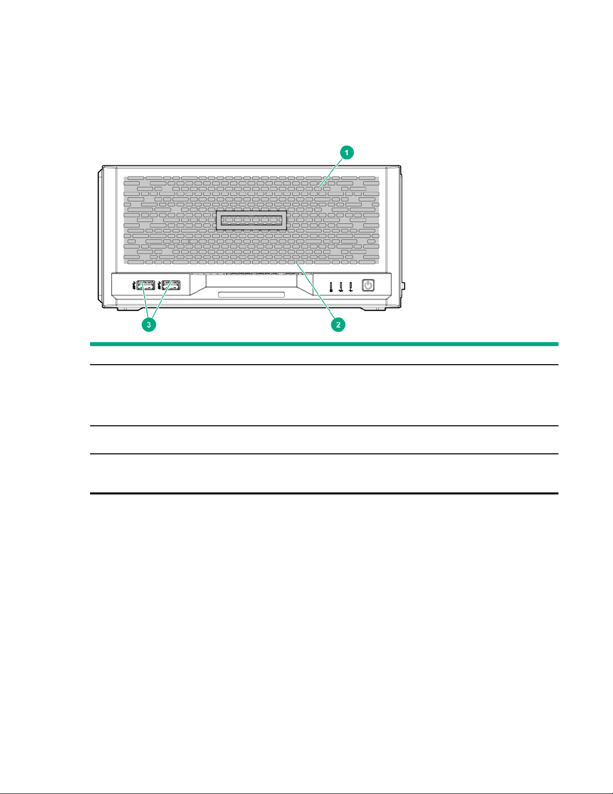
Front panel components
Item Component Description
1 Drive bays (4, behind the front bezel) By default, the drive bays support 35-inch LFF SATA drives.
To support 25-inch SFF drives, install the SFF drive converter
option.
2 Front bezel To access the drive bays, remove this bezel.
3 USB 32 Gen 2 Type-A ports
1
These ports are also known as SuperSpeed USB 10 Gb/s ports. The appropriate cable and compatible hardware are required to take
advantage of the 10 Gb/s data transfer speed.
1
Connect USB devices. These ports are backwards compatible with
earlier USB Type-A version devices.
6 Component identification
Page 7
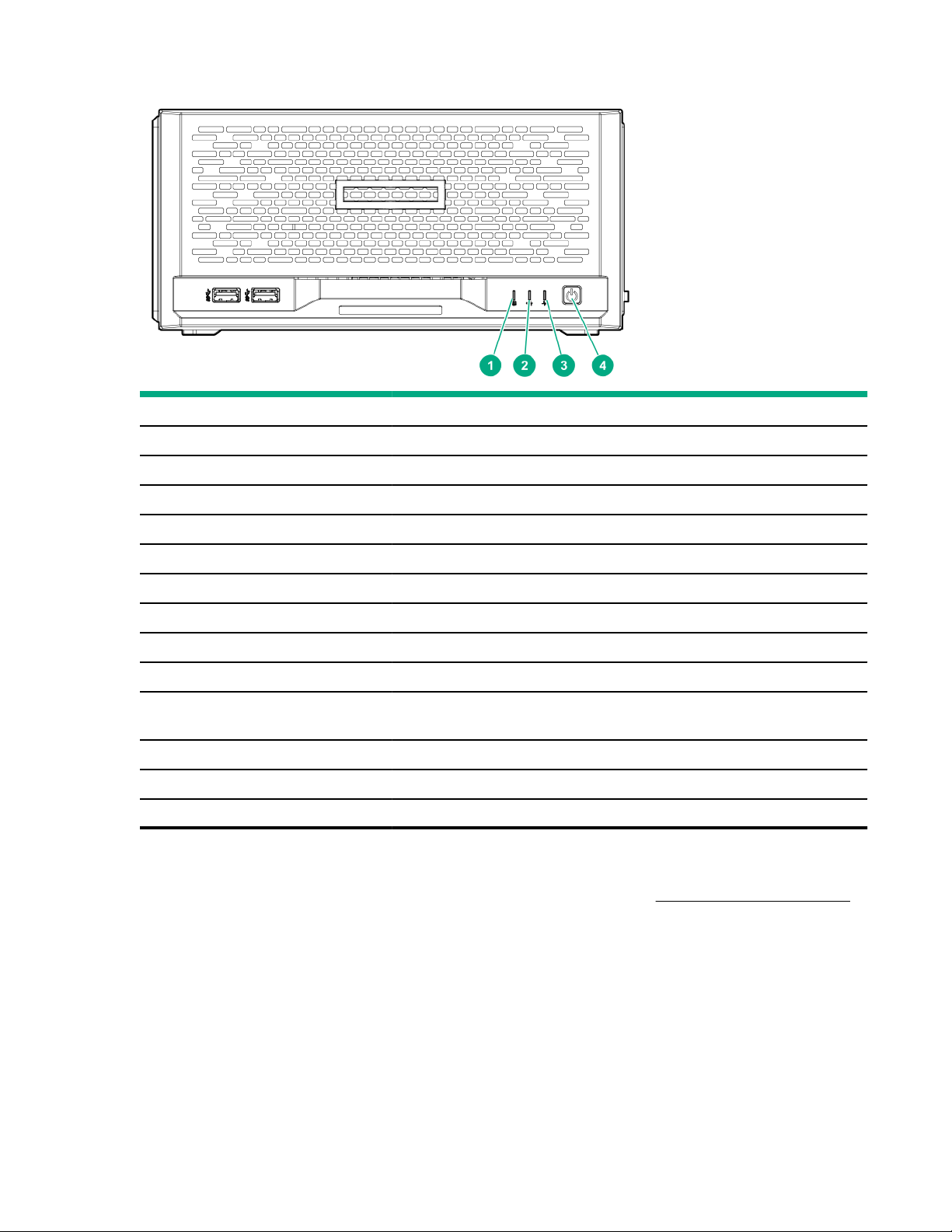
Front panel LEDs and button
Item Description Status Definition
2, 3
1
Flashing green Ongoing drive activity
O No drive activity
Solid green Linked to network
1 Drive activity LED
2 NIC status LED
Flashing green Network active
O No network activity
3 Health LED
3
Solid green Normal
Flashing green iLO is rebooting
4
4
4 Power on/Standby button
and system power LED
3
Flashing amber System degraded
Flashing red System critical
Solid green System on and normal operation
Flashing green Performing power-on sequence
Amber System in standby
O No power present
1
This LED only reflects the status of drives that are connected to the onboard SATA port.
2
This LED reflects the status of the onboard NIC ports managed by the embedded Intel I350-AM4 Ethernet Controller.
3
When these LEDs flash simultaneously, a power fault has occurred. For more information, see
4
If the health LED indicates a degraded or critical state, review the system IML or use iLO to review the system health status.
5
Facility power is not present, power cord is not attached, or power supply failure has occurred.
5
Front panel LED power fault codes.
Front panel LED power fault codes
The following table provides a list of power fault codes, and the subsystems that are aected. Not all power faults are
used by all servers.
Component identification
7
Page 8
Subsystem LED behavior
System board 1 flash
Processor 2 flashes
Memory 3 flashes
Riser board PCIe slots 4 flashes
FlexibleLOM 5 flashes
Removable HPE Smart Array SR Gen10 controller 6 flashes
System board PCIe slots 7 flashes
Power backplane or storage backplane 8 flashes
Power supply 9 flashes
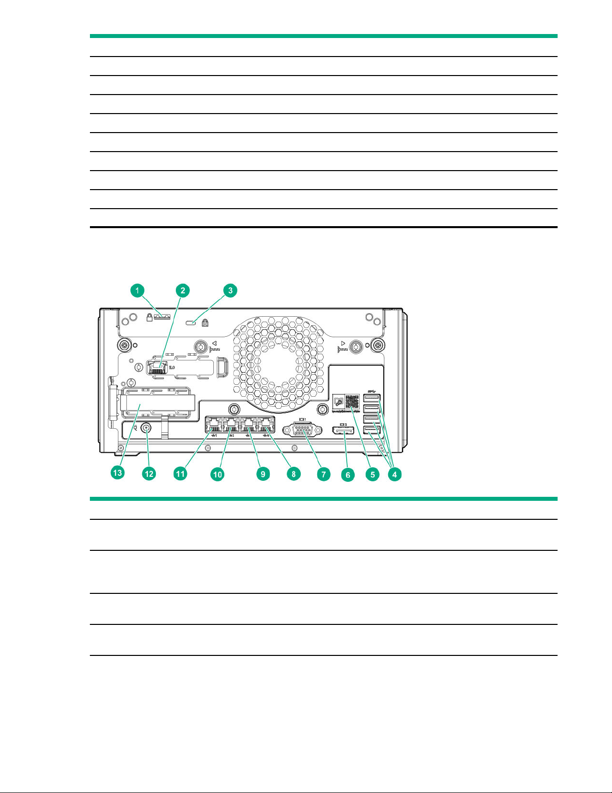
Rear panel components
Item Component Description
1 Padlock eye To lock the chassis cover and prevent access to the internal
2 iLO dedicated network port To connect iLO to a dedicated management network, connect a
3 Kensington security slot To secure the server to a heavy or immovable object, connect an
4 USB 32 Gen 1 Type-A ports
8 Component identification
components, attach a padlock here.
standard Ethernet cable here. This port requires the installation of the
iLO enablement option.
antitheft security cable here.
1
Connect USB devices. These ports are backwards compatible with
earlier USB Type-A version devices.
Table Continued
Page 9
Item Component Description
5 System QR code label To access the server mobile product page (https://www.hpe.com/
qref/microservergen10plus), use a QR code scanner app in your
smartphone to scan this label. This mobile page contains links to server
setup information, spare part numbers, QuickSpecs, troubleshooting
resources, and other useful product links.
6 DisplayPort 10 Connects to a high-resolution digital display device.
7 VGA port Connects to an analog display device.
8 1 Gb RJ-45 port 4
9 1 Gb RJ-45 port 3
10 1 Gb RJ-45 port 2
To connect the server to a wired network, connect a standard Ethernet
cable here.
11 1 Gb RJ-45 port 1/iLO shared
network port
12 Power jack Connects the power cord.
13 PCIe3 ×16 expansion slot Connects a half-height, half-length (low-profile) PCIe3 expansion board
1
These ports are also known as SuperSpeed USB 5 Gb/s ports. The appropriate cable and compatible hardware are required to take
advantage of the 5 Gb/s data transfer speed.
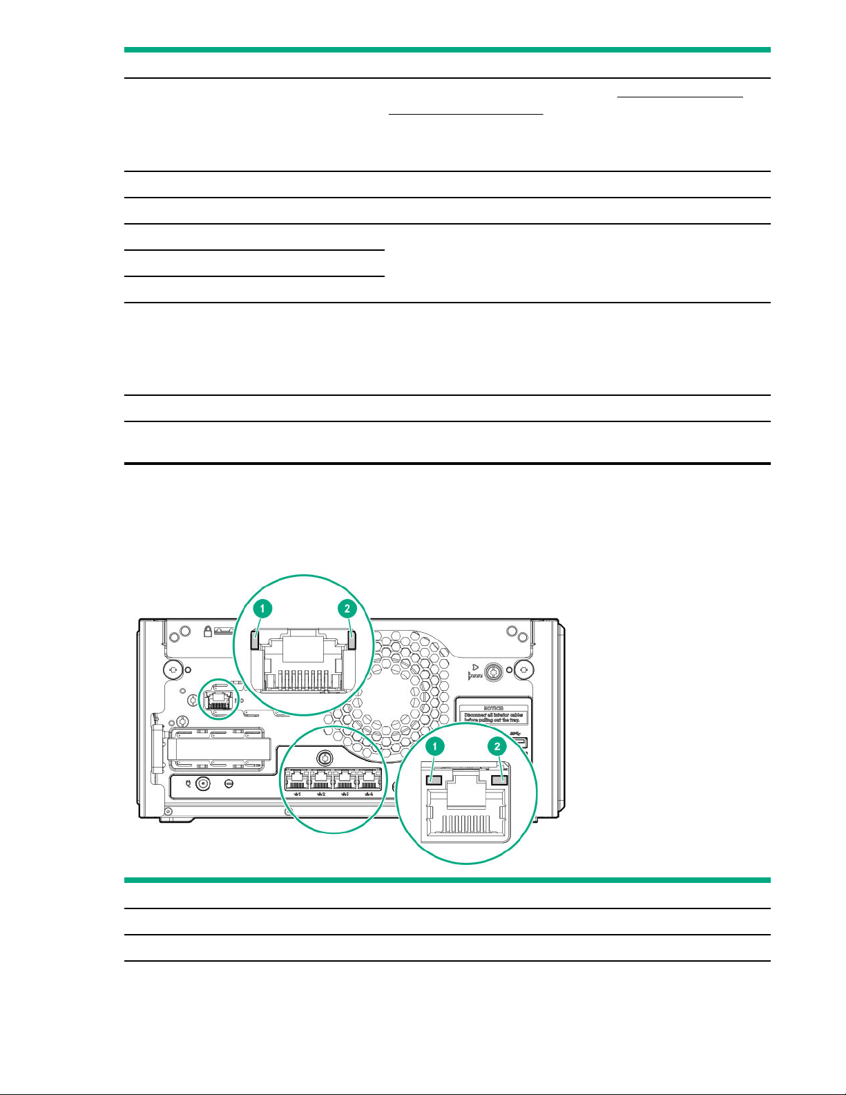
Rear panel LEDs
To connect the server to a wired network, connect a standard Ethernet
cable here.
When the iLO enablement option is installed, this port can be
configured to handle both server network and iLO network traic.
option.
Item
1 NIC link Solid green Network link
LED Status Definition
O No network link
Table Continued
Component identification 9
Page 10
Item LED Status Definition
2 NIC status Solid green Linked to network
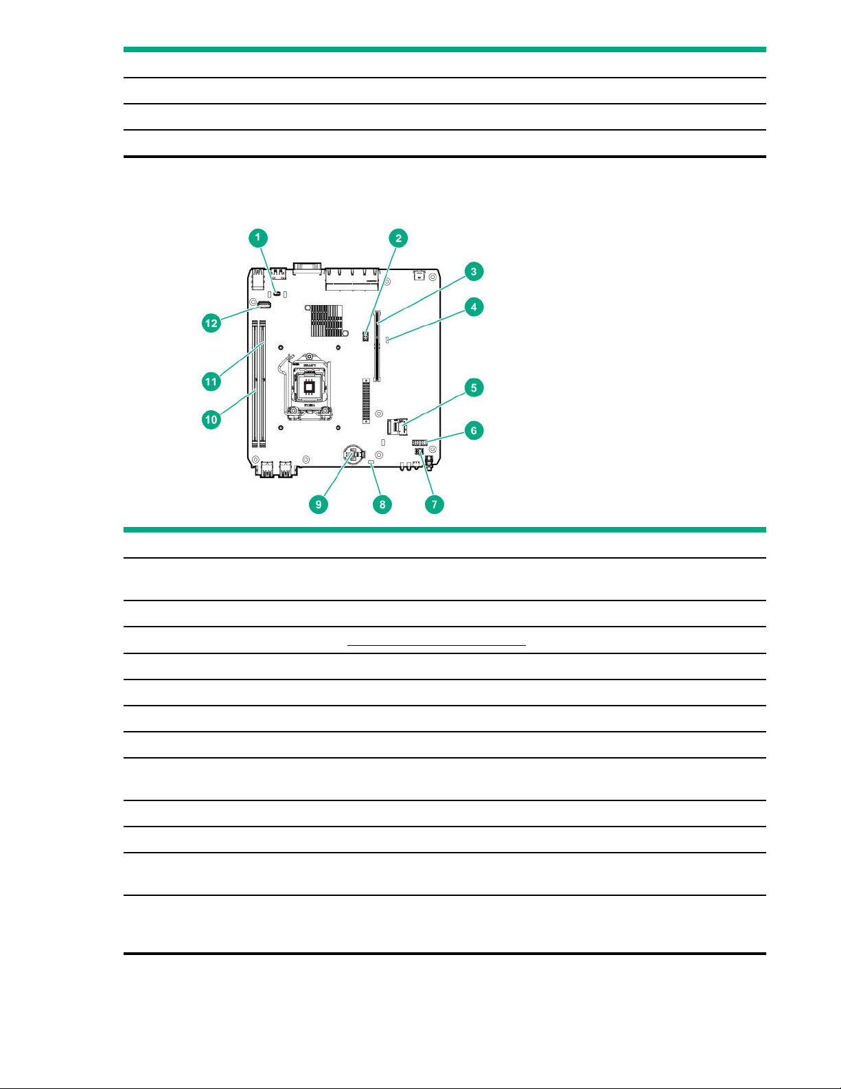
System board components
Flashing green Network active
O No network activity
Item Component Description
1 TPM connector This connector supports the HPE Trusted Platform Module 20 Gen10 option
(864279-B21) for data security.
2 Fan connector Connects the fan cable.
3 Riser connector Connects the system riser board.
4 System maintenance switch Use this switch to physically configure various server settings.
5 SATA 6GB/s port Connects the drive SATA cable.
6 Drive sideband connector Connects the drive sideband signal cable.
7 Drive power connector Connects the drive power cable.
8 CMOS header Use this header to clear the CMOS and reset the BIOS settings to their factory
default values.
9 System battery This battery provides power to the server CMOS and real-time clock.
10 DIMM slot 1B This slot supports standard UDIMMs with ECC only.
11 DIMM slot 2A This slot supports standard UDIMMs with ECC only. If only one UDIMM is
installed, install it in this slot.
12 Internal USB 20 port Connect a USB device, such as a USB security key or a USB drive key, intended
for permanent use. The internal connection avoids issues of clearance on the
front or rear of the server and prevents physical access to secure data.
10 Component identification
Page 11
System maintenance switch descriptions
Position Default Function
1
S1
S2 O Reserved
S3 O Reserved
S4 O Reserved
1
S5
3
S61, 2,
S7 O Reserved
S8 — Reserved
S9 — Reserved
O
O
O
O = iLO 5 security is enabled.
On = iLO 5 security is disabled.
O = Power-on password is enabled.
On = Power-on password is disabled.
O = No function
On = Restore default manufacturing settings
S10 — Reserved
S11 — Reserved
S12 — Reserved
1
To access the redundant ROM, set S1, S5, and S6 to On.
2
When the system maintenance switch position 6 is set to the On position, the system is prepared to restore all configuration settings to
their manufacturing defaults.
3
When the system maintenance switch position 6 is set to the On position and Secure Boot is enabled, some configurations cannot be
restored. For more information, see Secure Boot.
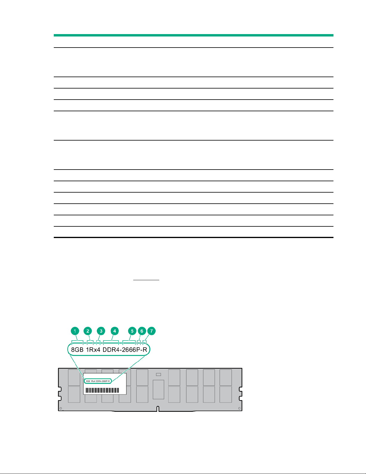
DIMM label identification
To determine DIMM characteristics, see the label attached to the DIMM. The information in this section helps you to use
the label to locate specific information about the DIMM.
Component identification
11
Page 12

Item Description Example
1 Capacity
2 Rank
3 Data width on DRAM
4 Memory generation
8 GB
16 GB
32 GB
64 GB
128 GB
1R = Single rank
2R = Dual rank
4R = Quad rank
8R = Octal rank
x4 = 4-bit
x8 = 8-bit
x16 = 16-bit
PC4 = DDR4
5 Maximum memory speed
6 CAS latency
7
DIMM type
2133 MT/s
2400 MT/s
2666 MT/s
2933 MT/s
P = CAS 15-15-15
T = CAS 17-17-17
U = CAS 20-18-18
V = CAS 19-19-19 (for RDIMM, LRDIMM)
V = CAS 22-19-19 (for 3DS TSV LRDIMM)
Y = CAS 21-21-21 (for RDIMM, LRDIMM)
Y = CAS 24-21-21 (for 3DS TSV LRDIMM)
R = RDIMM (registered)
L = LRDIMM (load reduced)
12 Component identification
E = Unbuered ECC (UDIMM)
Page 13
For more information about product features, specifications, options, configurations, and compatibility, see the HPE DDR4
SmartMemory QuickSpecs on the Hewlett Packard Enterprise website (https://www.hpe.com/support/
DDR4SmartMemoryQS).
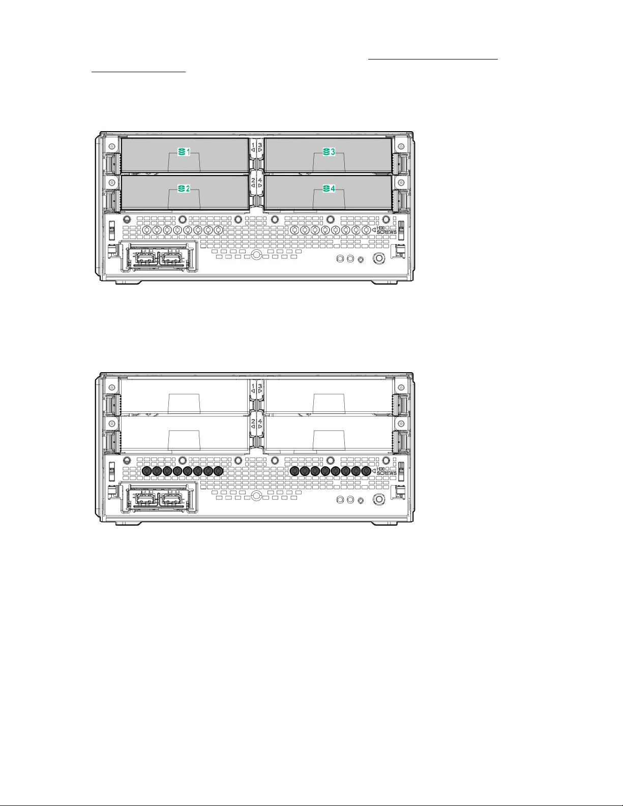
Drive bay numbering
Drive screws
There are 16 T-15 Torx screws located under the drive bays. Use these screws to install drives in the server.
Component identification
13
Page 14
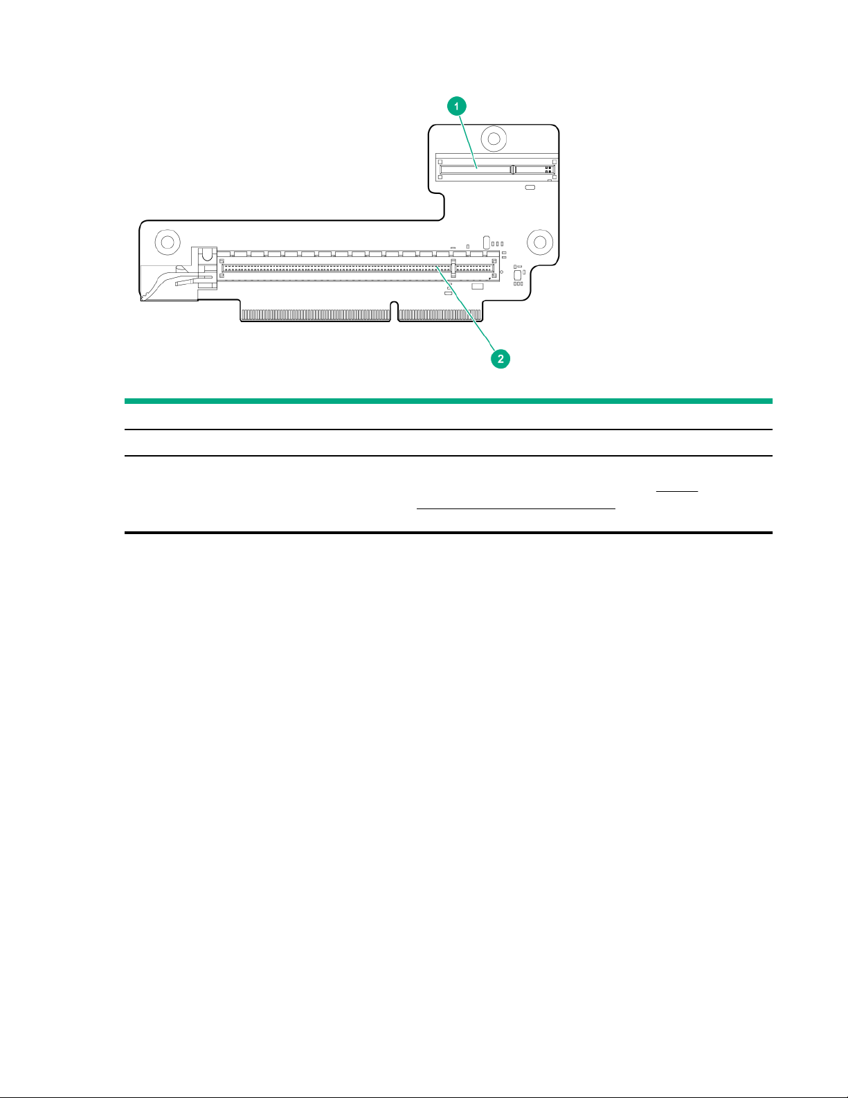
Riser board slots
Item Description Supported option
1 iLO dedicated network module slot Install the iLO enablement option here.
2 PCIe3 ×16 expansion slot Install a half-height PCIe3 ×16 expansion board here. See the
product QuickSpecs on the server website at https://
www.hpe.com/servers/microserver for list of supported
expansion options.
14 Component identification
Page 15

Operations
This chapter describes the hardware operations carried out prior to and after installing or removing a hardware option, or
performing a server maintenance or troubleshooting procedure.
Before performing these hardware operations, review and observe the server warnings and cautions.
Power up the server
To power up the server, use one of the following methods:
• Press the Power On/Standby button.
• Use the virtual power button through iLO.
Power down the server
Before powering down the server for any upgrade or maintenance procedures, perform a backup of critical server data
and programs.
IMPORTANT: When the server is in standby mode, auxiliary power is still being provided to the system.
To power down the server, use one of the following methods:
• Press and release the Power On/Standby button.
This method initiates a controlled shutdown of applications and the OS before the server enters standby mode.
• Press and hold the Power On/Standby button for more than 4 seconds to force the server to enter standby mode.
This method forces the server to enter standby mode without properly exiting applications and the OS. If an
application stops responding, you can use this method to force a shutdown.
• Use a virtual power button selection through iLO 5.
This method initiates a controlled remote shutdown of applications and the OS before the server enters standby
mode.
Before proceeding, verify that the server is in standby mode by observing that the system power LED is amber.
Removing the front bezel
To access the drive bays, remove the front bezel.
Procedure
1. Power down the server.
2. Disconnect the power cord from the AC source.
3. Remove the power adapter cord from the power cord clip, and then disconnect the power adapter from the server.
4. Disconnect all peripheral cables from the server.
5. If the server is in a vertical orientation, position the server in a horizontal orientation.
Operations
15
Page 16
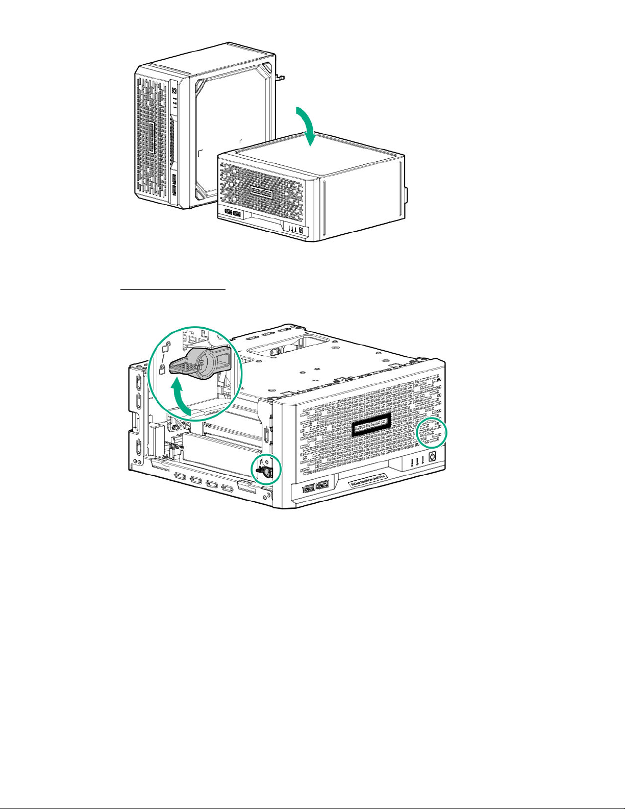
6. If the front bezel is locked, do the following:
a. Remove the chassis cover.
Switch the bezel locks upward.
b.
To remove an unlocked front bezel, do the following:
7.
16
a. Pivot the bottom part of the bezel upward (callout 1).
b. Release the bezel tabs from their chassis openings (callout 2).
Operations
Page 17
Installing the front bezel
Procedure
Make sure that the bezel locks are in the unlocked position.
1.
2. Install the front bezel:
a. Insert the bezel tabs to their chassis openings (callout 1).
b. Pivot the bottom part of the bezel downward (callout 2).
Operations
17
Page 18
3. If you prefer to secure the bezel to the chassis, switch the bezel locks downward.
If removed, install the chassis cover.
4.
If removed, install the security padlock and/or the Kensington security lock.
5.
For more information, see the lock documentation.
Connect all peripheral cables to the server.
6.
Connect the power adapter to the server, and then secure the power adapter cord in the power cord clip.
7.
8. Connect the power cord to the AC source.
Power up the server.
9.
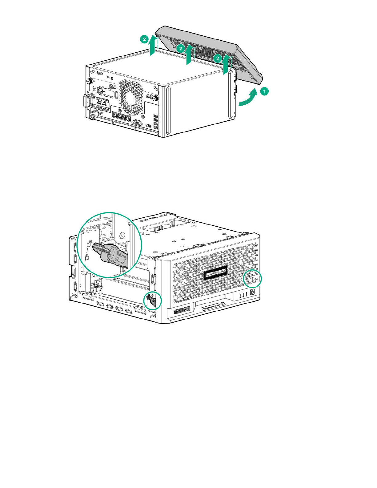
Removing the chassis cover
To access the front bezel locks, remove the chassis cover.
18
Operations
Page 19
Procedure
1. Power down the server.
2. Disconnect the power cord from the AC source.
3. Remove the power adapter cord from the power cord clip, and then disconnect the power adapter from the server.
4. Disconnect all peripheral cables from the server.
5. If installed, unlock and remove the security padlock and/or the Kensington security lock.
For more information, see the lock documentation.
6. If the server is in a vertical orientation, position the server in a horizontal orientation.
Remove the chassis cover:
7.
Remove the cover thumbscrews.
a.
If the thumbscrews are too tight, use a T-15 Torx screwdriver to remove them (callout 1).
Slide the cover about half an inch towards the rear panel until the arrowhead markers on the front edge of the
b.
chassis are exposed, and then detach the cover from the server (callout 2).
Operations
19
Page 20
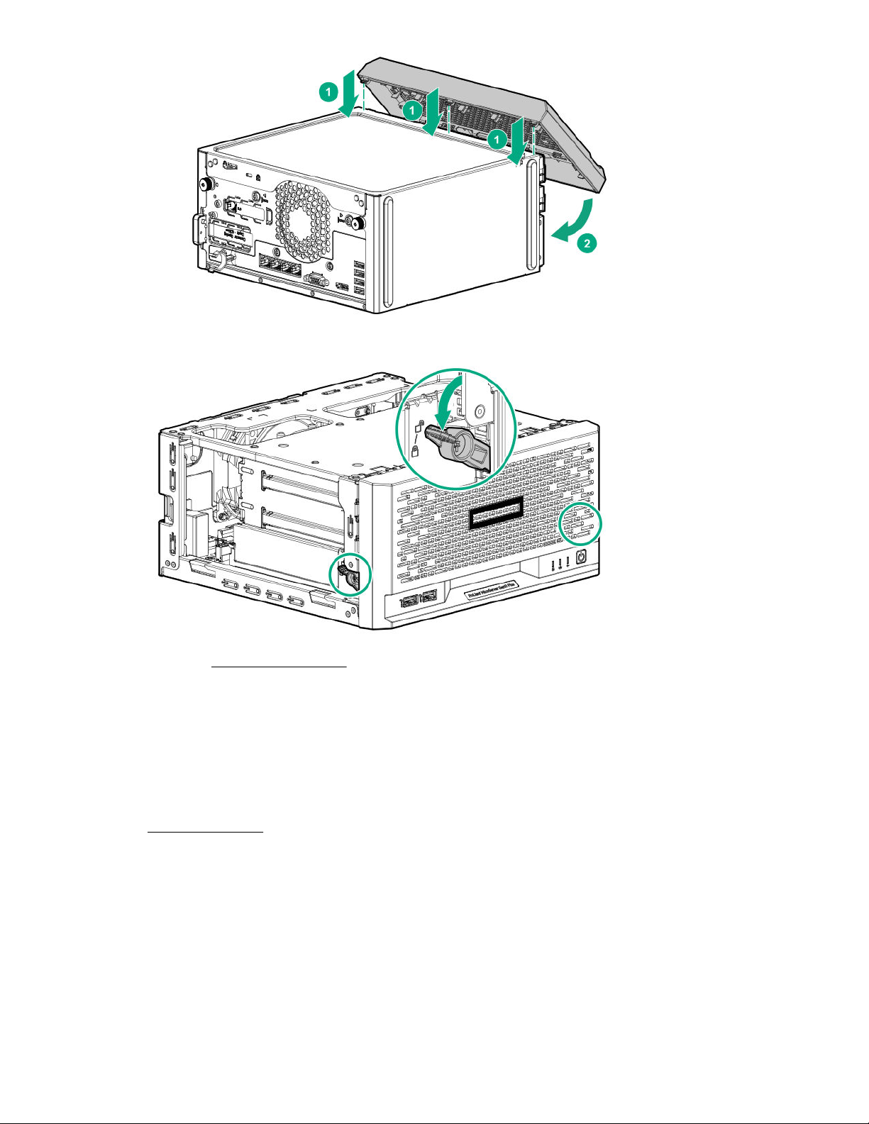
Installing the chassis cover
Procedure
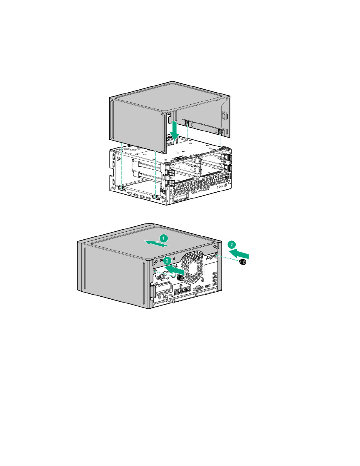
1. Install the chassis cover:
a. Insert the cover tabs to their chassis openings. Make sure that the cover is flushed against the top of the chassis.
Slide the chassis cover towards the front panel (callout 1), and then install the chassis thumbscrews (callout 2).
b.
2. If removed, install the security padlock and/or the Kensington security lock.
For more information, see the lock documentation.
3. Connect all peripheral cables to the server.
4. Connect the power adapter to the server, and then secure the power adapter cord in the power cord clip.
5. Connect the power cord to the AC source.
Power up the server.
6.
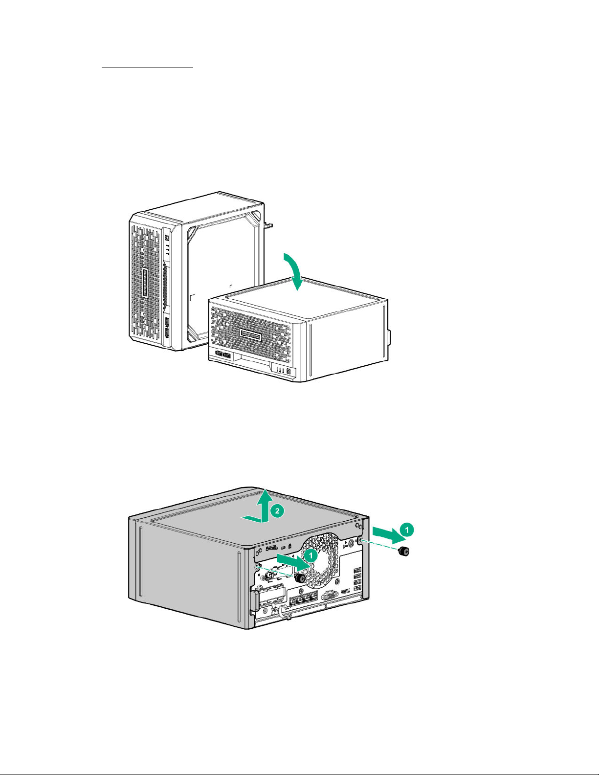
Removing the system board assembly
To access most internal components, remove the system board assembly.
20
Operations
Page 21
Prerequisites
Before you perform this procedure, make sure that you have a T-15 Torx screwdriver available.
Procedure
1. Power down the server.
2. Disconnect the power cord from the AC source.
3. Remove the power adapter cord from the power cord clip, and then disconnect the power adapter from the server.
4. Disconnect all peripheral cables from the server.
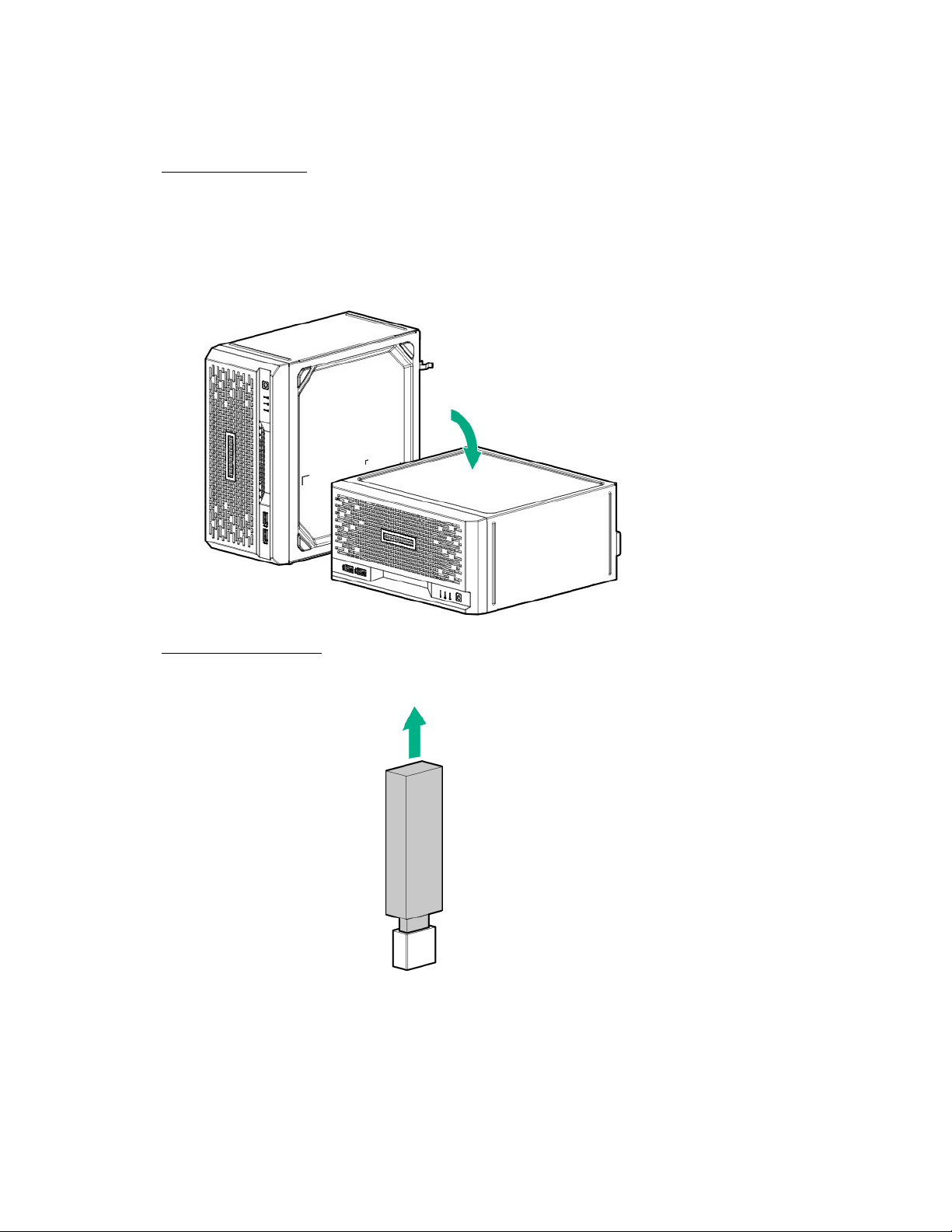
5. If the server is in a vertical orientation, position the server in a horizontal orientation.
Remove the chassis cover.
6.
If a tall internal USB device is installed, remove the device.
7.
8. Remove the system board tray screws.
Operations
21
Page 22
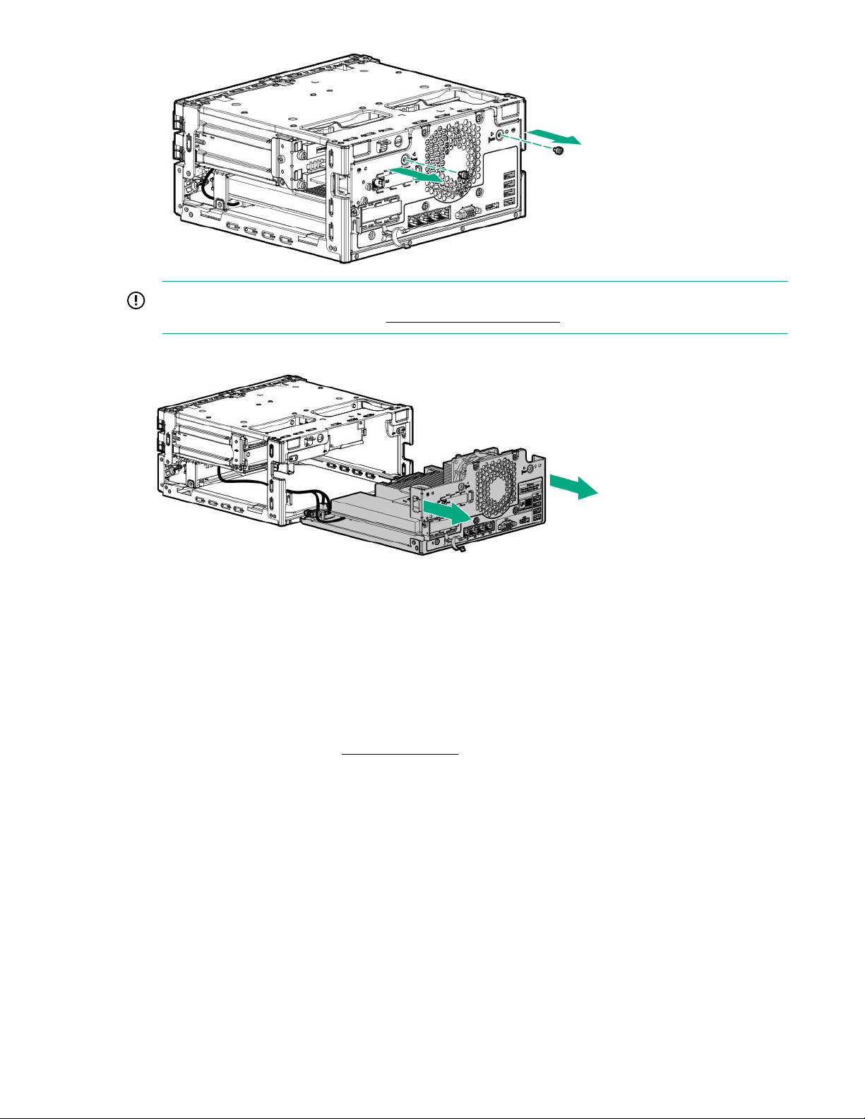
IMPORTANT: The storage cables connect the system board to the chassis. If you are completely separating the
system board assembly from the chassis, disconnect the storage cabling.
9. Use the blue touchpoints on both sides of the tray to pull out the system board assembly from the chassis.
Installing the system board assembly
Prerequisites
Before you perform this procedure, make sure that you have a T-15 Torx screwdriver available.
22
Procedure
If the storage cables were removed, reconnect the cables.
1.
2. Install the system board assembly:
a. Slide the system board assembly into the chassis (callout 1).
b. Install the system board assembly screws (callout 2).
Operations
Page 23
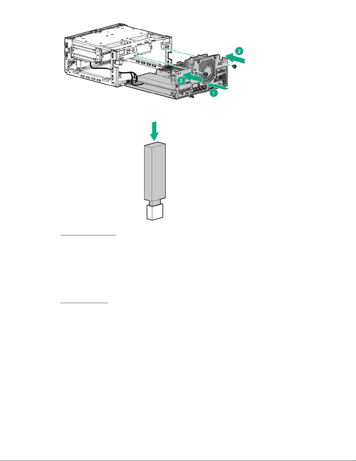
3. If removed, install the internal USB device.
Install the chassis cover.
4.
If removed, install the security padlock and/or the Kensington security lock.
5.
For more information, see the lock documentation.
Connect all peripheral cables to the server.
6.
Connect the power adapter to the server, and then secure the power adapter cord in the power cord clip.
7.
Connect the power cord to the AC source.
8.
Power up the server.
9.
Operations
23
Page 24

Setup
Optional service
Delivered by experienced, certified engineers, Hewlett Packard Enterprise support services help you keep your servers up
and running with support packages tailored specifically for HPE ProLiant systems. Hewlett Packard Enterprise support
services let you integrate both hardware and software support into a single package. A number of service level options are
available to meet your business and IT needs.
Hewlett Packard Enterprise support services oer upgraded service levels to expand the standard product warranty with
easy-to-buy, easy-to-use support packages that will help you make the most of your server investments. Some of the
Hewlett Packard Enterprise support services for hardware, software or both are:
• Foundation Care – Keep systems running.
◦ 6-Hour Call-to-Repair
◦ 4-Hour 24x7
◦ Next Business Day
• Proactive Care – Help prevent service incidents and get you to technical experts when there is one.
◦ 6-Hour Call-to-Repair
1
1
◦ 4-Hour 24x7
◦ Next Business Day
• Deployment service for both hardware and software
• Hewlett Packard Enterprise Education Services – Help train your IT sta.
1
The time commitment for this repair service might vary depending on the geographical region of site. For more service
information available in your site, contact your local Hewlett Packard Enterprise support center.
For more information on Hewlett Packard Enterprise support services, see the Hewlett Packard Enterprise website.
Initial system installation
Depending on your technical expertise and the complexity of the product, for the initial system installation, select one of
the following options:
• Ordering the HPE Installation Service
• Setting up the server
HPE Installation Service
HPE Installation Service provides basic installation of Hewlett Packard Enterprise branded equipment, software products,
as well as HPE-supported products from other vendors that are sold by HPE or by HPE authorized resellers. The
Installation Service is part of a suite of HPE deployment services that are designed to give users the peace of mind that
comes from knowing that their HPE and HPE-supported products have been installed by an HPE specialist.
24
The HPE Installation Service provides the following benefits:
Setup
Page 25

• Installation by an HPE authorized technical specialist.
• Verification prior to installation that all service prerequisites are met.
• Delivery of the service at a mutually scheduled time convenient to your organization.
• Allows your IT resources to stay focused on their core tasks and priorities.
• Full coverage during the warranty period for products that require installation by an HPE authorized technical
specialist.
For more information on the features, limitations, provisions, and ordering information of the HPE Installation Service, see
this Hewlett Packard Enterprise website:
https://www.hpe.com/support/installation-service
Setting up the server
Prerequisites
Before setting up the server:
• Download the latest SPP:
https://www.hpe.com/servers/spp/download
Support validation required
• Verify that your OS or virtualization software is supported:
https://www.hpe.com/info/ossupport
• Read the HPE UEFI requirements for ProLiant servers on the HPE website:
https://www.hpe.com/support/Gen10UEFI
If the UEFI requirements are not met, you might experience boot failures or other errors when installing the operating
system.
• Obtain the storage driver if needed:
◦ Download it from the HPE Support Center website:
https://www.hpe.com/support/hpesc
◦ Extract it from the SPP.
• Read the operational requirements for the server:
Operational requirements
• Read the safety and compliance information on the HPE website:
https://www.hpe.com/support/safety-compliance-enterpriseproducts
• Take note of the iLO hostname and default login credentials on the iLO information label on the bottom of the server.
Procedure
Unbox the server
1. Unbox the server and verify the contents:
Setup
25
Page 26
• Server
• Power cord and adapter
• Antislip rubber strips (2)
• Printed setup documentation
The server does not ship with OS media. All system software and firmware is preloaded on the server.
Install the hardware options
2. (Optional) Install the hardware options. For installation instructions, see the server user guide on the HPE website:
https://www.hpe.com/info/microservergen10plus-docs
Orient the server
3. Select the server orientation:
Position the server in a horizontal orientation.
•
• Position the server in a vertical orientation.
Connect the peripheral devices and the power cord
IMPORTANT: The iLO shared connectivity of the RJ-45 port 1 is dependent on the presence of the iLO
enablement module. If this optional module is not installed, use an in-band communication method for accessing
iLO.
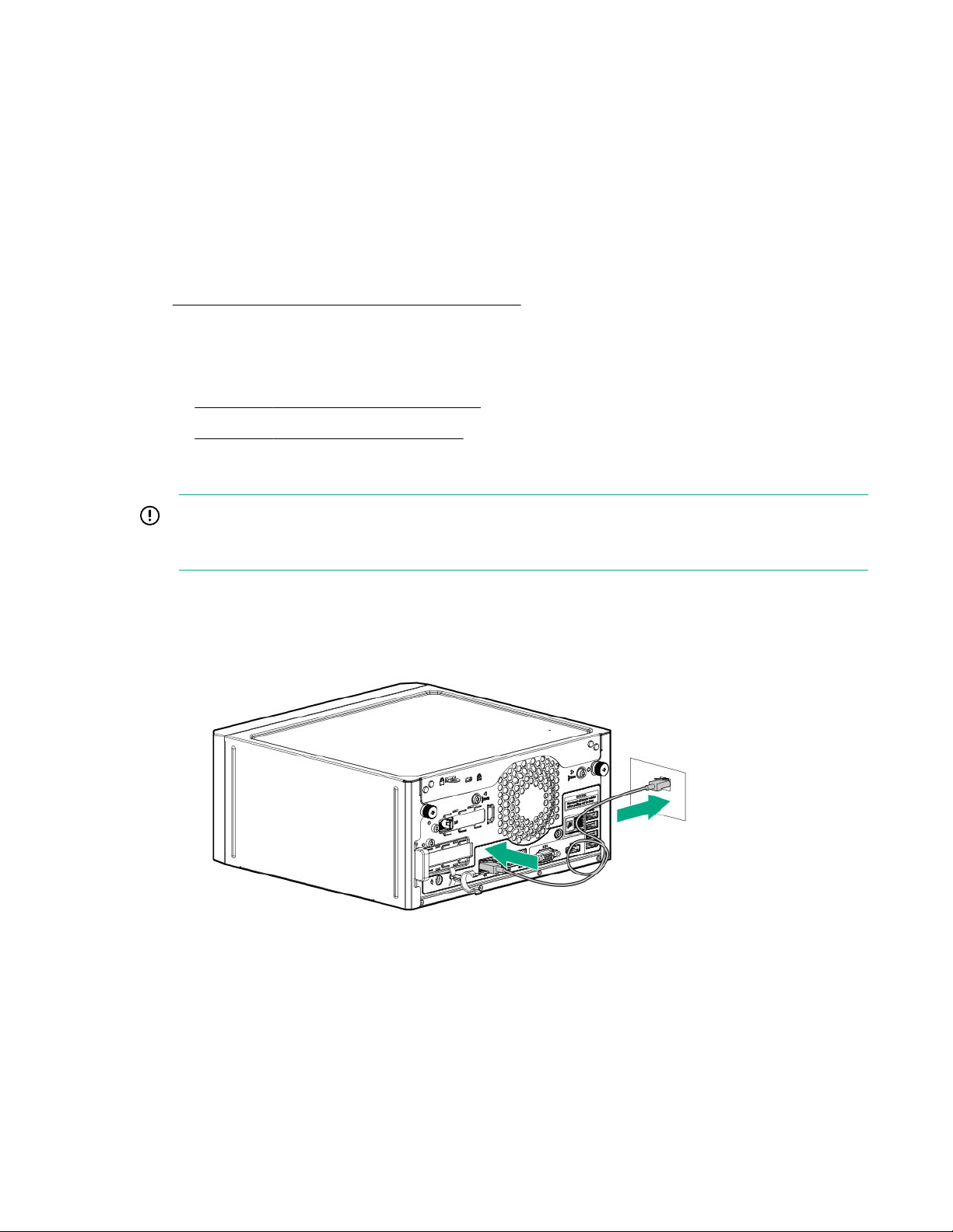
Connect the network cable:
4.
Connect one end of the network cable to the NIC port.
a.
Connect the other end of the network cable to a network jack or a network device, such as router or LAN switch.
b.
5. Connect the power cord:
a. Connect the power adapter to the server power jack with the connector secured in the power cord clip (callout
1).
b. Connect the power cord to the adapter (callout 2).
26
c. Connect the power cord to the AC power source (callout 3).
Setup
Page 27
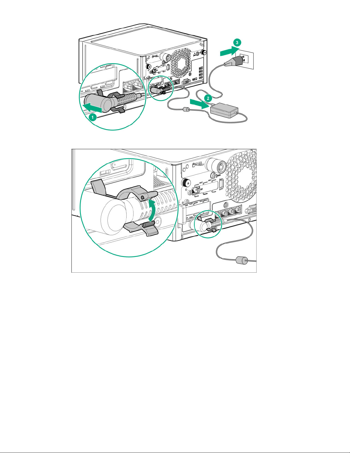
d. Close the power cord clip until it clicks into place.
Decide how to manage the server:
6.
• Locally: Use a KVM switch or a connect a keyboard, monitor, and mouse.
Setup
27
Page 28

• Remotely: Connect to the iLO web interface and run a remote console:
This action requires the iLO enablement option for remote iLO access.
Verify the following:
a.
◦ iLO is licensed to use the remote console feature.
If iLO is not licensed, visit the HPE website:
https://www.hpe.com/info/ilo
◦ The iLO dedicated or shared network port is connected to a secure network.
Using a browser, navigate to the iLO web interface, and then log in.
b.
https://<iLO hostname or IP address>
Note the following:
◦ The iLO hostname and default login credentials on the iLO information label on the bottom of the server.
◦ If a DHCP server assigns the IP address, the IP address appears on the boot screen.
◦ If a static IP address is assigned, use that IP address.
In the side navigation, click the Remote Console & Media link, and then launch a remote console.
c.
Power on the server
28
7. Press the Power On/Standby button.
For remote management, use the iLO virtual power button.
8. Using the SPP,
• System ROM
• Storage controller
• Network controller
• Intelligent Provisioning
Set up the storage
Setup
update the following:
Page 29

9. Set up the storage. Do one of the following:
• To configure the server to boot from a SAN, see the following guide:
https://www.hpe.com/info/boot-from-san-config-guide
• If an HPE Smart Array controller is installed, use the HPE Smart Storage Administrator to create arrays:
a. From the boot screen, press F10 to run Intelligent Provisioning.
b. From Intelligent Provisioning, run HPE Smart Storage Administrator.
• If no controller option is installed, do one of the following:
◦ AHCI is enabled by default. You can deploy an OS or virtualization software.
◦ Disable AHCI, enable software RAID, and then create an array:
a. From the boot screen, press F9 to run UEFI System Utilities.
b. From the UEFI System Utilities screen, select System Configurations > BIOS/Platform Configuration
(RBSU) > Storage Options > SATA Controller Options > Embedded SATA Configuration > Smart
Array SW RAID Support.
c. Enable Smart Array SW RAID Support.
Save the configuration and reboot the server.
d.
Create an array:
e.
From the boot screen, press F9 to run UEFI System Utilities.
I.
From the UEFI System Utilities screen, select System Configuration > Embedded Storage: HPE
II.
Smart Storage S100i SR Gen10 > Array Configuration > Create Array.
Deploy an OS or virtualization software
Deploy an OS or virtualization software. Do one of the following:
10.
• Press F10 at the POST screen.
You are prompted to select whether you want to enter the Intelligent Provisioning or HPE Rapid Setup Software
mode. After you have selected a mode, you must reprovision the server to change the mode that launches when
you boot to F10.
• Manually deploy an OS:
Insert the installation media.
a.
For remote management, click Virtual Drives in the iLO remote console to mount images, drivers, or files to a
virtual folder. If a storage driver is required to install the OS, use the virtual folder to store the driver.
b. Press F11 at boot screen to select the boot device.
c. After the OS installed,
update the drivers.
Register the server
11. To experience quick service and
https://myenterpriselicense.hpe.com
eicient support, register the server at the HPE website:
Setup
29
Page 30

Server orientation options
The server can be oriented in a horizontal or vertical setup depending on the available space in the installation site.
Position the server in a horizontal orientation
There are four antislip rubber pads preinstalled on the base of the server for a horizontal setup.
In a horizontal setup, you can stack up to three MicroServers on top of each other.
Position the server in a vertical orientation
The server can be oriented vertically for a smaller footprint setup. There are two pairs of divots on both sides of the server
for attaching the antislip rubber strips. Two antislip rubber strips are shipped with the server.
30
Setup
Page 31

Prerequisites
Before you perform this procedure, make sure that you have the following items available:
• Isopropyl alcohol wipe
• Antislip rubber strips
Procedure
1. Use an isopropyl alcohol wipe to clean the divots on the side of the server. Allow the alcohol to evaporate before
continuing.
Peel o the protective liner from the rubber strips.
2.
Attach the strips onto the divots. To ensure proper adhesion, press along the entire strip.
3.
Position the server in a vertical orientation.
4.
Setup
31
Page 32

Operational requirements
Site requirements
The server may be located in an oice space or a purpose-made equipment room. The location must:
• Comply with local health and safety regulations.
• Be clean, tidy, and free of excessive dust and vibration.
• Be in an area in which the server cannot easily be disconnected from its power source.
• Not be adjacent to or underneath any area or piece of equipment where liquid is stored.
• Not be in a place where the server might be bumped, scratched, or disturbed.
• Be within an area that is ideally locked or at minimum not accessible to unauthorized personnel.
• Be within patching distance, directly or via cable management cross-patches, of the location of the WAN connection
and the switch that supplies the oice/room floor network ports.
Space and airflow requirements
Leave at least a 10 cm (4 in) clearance space at the front and back of the server for proper ventilation.
CAUTION: The server draws in cool air through the ventilation openings on the front side, and expels warm air
through the ventilation openings on the rear side. Do not block these openings. Failure to observe this caution will
result in improper airflow and
insuicient cooling that can lead to thermal damage.
Temperature requirements
To ensure continued safe and reliable equipment operation, install or position the system in a well-ventilated, climatecontrolled environment.
The maximum recommended ambient operating temperature (TMRA) for most server products is 35°C (95°F). The
temperature in the room where the rack is located must not exceed 35°C (95°F).
32
Setup
Page 33

CAUTION: To reduce the risk of damage to the equipment when installing third-party options:
• Do not permit optional equipment to impede airflow around the server or to increase the internal rack
temperature beyond the maximum allowable limits.
• Do not exceed the manufacturer’s TMRA.
Power requirements
Installation of this equipment must comply with local and regional electrical regulations governing the installation of
information technology equipment by licensed electricians. This equipment is designed to operate in installations covered
by NFPA 70, 1999 Edition (National Electric Code) and NFPA-75, 1992 (code for Protection of Electronic Computer/Data
Processing Equipment). For electrical power ratings on options, refer to the product rating label or the user
documentation supplied with that option.
WARNING: To reduce the risk of personal injury, fire, or damage to the equipment, do not overload the AC supply
branch circuit that provides power to the rack. Consult the electrical authority having jurisdiction over wiring and
installation requirements of your facility.
CAUTION: Protect the server from power fluctuations and temporary interruptions with a regulating
uninterruptible power supply. This device protects the hardware from damage caused by power surges and voltage
spikes and keeps the system in operation during a power failure.
Electrical grounding requirements
The server must be grounded properly for proper operation and safety. In the United States, you must install the
equipment in accordance with NFPA 70, 1999 Edition (National Electric Code), Article 250, as well as any local and
regional building codes. In Canada, you must install the equipment in accordance with Canadian Standards Association,
CSA C221, Canadian Electrical Code. In all other countries, you must install the equipment in accordance with any
regional or national electrical wiring codes, such as the International Electrotechnical Commission (IEC) Code 364, parts 1
through 7. Furthermore, you must be sure that all power distribution devices used in the installation, such as branch
wiring and receptacles, are listed or certified grounding-type devices.
Because of the high ground-leakage currents associated with multiple servers connected to the same power source,
Hewlett Packard Enterprise recommends the use of a PDU that is either permanently wired to the building’s branch circuit
or includes a nondetachable cord that is wired to an industrial-style plug. NEMA locking-style plugs or those complying
with IEC 60309 are considered suitable for this purpose. Using common power outlet strips for the server is not
recommended.
Server warnings and cautions
WARNING: To reduce the risk of personal injury, electric shock, or damage to the equipment, disconnect the power
cord to remove power from the server. Pressing the Power On/Standby button does not shut
completely. Portions of the power supply and some internal circuitry remain active until AC power is removed.
WARNING: To reduce the risk of personal injury from hot surfaces, allow the drives and the internal system
components to cool before touching them.
o system power
CAUTION: Protect the server from power fluctuations and temporary interruptions with a regulating UPS. This
device protects the hardware from damage caused by power surges and voltage spikes and keeps the server in
operation during a power failure.
Setup 33
Page 34

CAUTION: To prevent improper airflow and insuicient cooling that can lead to thermal damage, observe the
following:
• Do not operate the server with the front bezel or chassis cover removed.
• Periodically clean the dust filter on the inner surface of the front bezel.
CAUTION: To prevent damage to electrical components, properly ground the server before beginning any
installation procedure. Improper grounding can cause electrostatic discharge.
CAUTION: To avoid data loss, Hewlett Packard Enterprise recommends that you back up all server data before
installing or removing a hardware option, or performing a server maintenance or troubleshooting procedure.
Electrostatic discharge
Be aware of the precautions you must follow when setting up the system or handling components. A discharge of static
electricity from a finger or other conductor may damage system boards or other static-sensitive devices. This type of
damage may reduce the life expectancy of the system or component.
To prevent electrostatic damage:
• Avoid hand contact by transporting and storing products in static-safe containers.
• Keep electrostatic-sensitive parts in their containers until they arrive at static-free workstations.
• Place parts on a grounded surface before removing them from their containers.
• Avoid touching pins, leads, or circuitry.
• Always be properly grounded when touching a static-sensitive component or assembly. Use one or more of the
following methods when handling or installing electrostatic-sensitive parts:
◦ Use a wrist strap connected by a ground cord to a grounded workstation or computer chassis. Wrist straps are
flexible straps with a minimum of 1 megohm ±10 percent resistance in the ground cords. To provide proper
ground, wear the strap snug against the skin.
◦ Use heel straps, toe straps, or boot straps at standing workstations. Wear the straps on both feet when standing
on conductive floors or dissipating floor mats.
◦ Use conductive field service tools.
◦ Use a portable field service kit with a folding static-dissipating work mat.
If you do not have any of the suggested equipment for proper grounding, have an authorized reseller install the part.
For more information on static electricity or assistance with product installation, contact an authorized reseller.
POST screen options
When the server is powered on, the POST screen is displayed. The following options are displayed:
34
• System Utilities (F9)
Use this option to configure the system BIOS.
• Intelligent Provisioning (F10)
Use this option to deploy an operating system or configure storage.
Setup
Page 35

• Boot order (F11)
Use this option to make a one-time boot selection.
• Network boot (F12)
Use this option to boot the server from the network.
Installing or deploying an operating system
Before installing an operating system, observe the following:
• Be sure to read the HPE UEFI requirements for ProLiant servers on the Hewlett Packard Enterprise website. If UEFI
requirements are not met, you might experience boot failures or other errors when installing the operating system.
• Update firmware before using the server for the first time, unless software or components require an older version. For
more information, see
• For the latest information on supported operating systems, see the Hewlett Packard Enterprise website.
• The server does not ship with OS media. All system software and firmware is preloaded on the server.
Keeping the system current.
Setup 35
Page 36

Hardware options installation
This chapter provides detailed instructions on how to install hardware options.
For more information on supported options, see the product QuickSpecs on the HPE ProLiant MicroServer Gen10 Plus
website at:
https://www.hpe.com/servers/microserver
To view the warranty for your server and supported options, see Warranty information.
Introduction
Install any hardware options before initializing the server. If multiple options are being installed, read the installation
instructions for all the hardware options to identify similar steps and streamline the installation process.
WARNING: To reduce the risk of personal injury from hot surfaces, allow the drives and the internal system
components to cool before touching them.
CAUTION: To prevent damage to electrical components, properly ground the server before beginning any
installation procedure. Improper grounding can cause electrostatic discharge.
Drive options
Drive support information
• This server has four drive bays that support:
◦ Non-hot-plug LFF SATA hard drives
◦ Non-hot-plug SFF SATA hard drives and solid-state drives (SSD)
SFF drive configurations require the SFF-to-LFF drive converter option.
• The embedded HPE Smart Array S100i SR Gen10 Controller supports SATA drive installation. This controller supports
RAID levels 0, 1, 5, and 10.
• To support better reliability, security and eiciency in storage, install a Smart Array Gen10 type-p controller option.
Drive installation guidelines
• Populate drive bays based on the drive numbering sequence. Start from the drive bay with the lowest device
number.
• All drives grouped into the same drive array must meet the following criteria:
◦ They must be either all hard drives or all solid-state drives.
◦ Drives should be the same capacity to provide the greatest storage space eiciency when drives are grouped
together into the same drive array.
• The system automatically sets all device numbers.
36
Hardware options installation
Page 37

Installing an LFF drive
The LFF drives supported in this server do not require a drive caddy or a drive carrier to install. You only have to use the
drive mounting screws on the chassis.
Prerequisites
Before you perform this procedure, make sure that you have a T-15 Torx screwdriver available.
Procedure
1. Power down the server.
2. Disconnect the power cord from the AC source.
3. Remove the power adapter cord from the power cord clip, and then disconnect the power adapter from the server.
4. Disconnect all peripheral cables from the server.
5. If installed, unlock and remove the security padlock and/or the Kensington security lock.
For more information, see the lock documentation.
6. If the server is in a vertical orientation, position the server in a horizontal orientation.
Remove the front bezel.
7.
Remove four drive screws from the front panel.
8.
Hardware options installation
37
Page 38

9. Install the screws in the drive.
Slide the drive into the bay until it clicks into place.
10.
11. Install the front bezel.
12. Connect all peripheral cables to the server.
13. Connect the power adapter to the server, and then secure the power adapter cord in the power cord clip.
14. Connect the power cord to the AC source.
Power up the server.
15.
16. Determine the status of the server drives.
38
Hardware options installation
Page 39

The installation is complete.
To configure arrays, see the HPE Smart Array SR Gen10 Configuration Guide at the Hewlett Packard Enterprise
website.
Installing an SFF drive
To install SFF hard drives and SSDs, use the SFF-to-LFF drive converter option.
In general, SFF hard drives require as little as half the power and generate significantly less heat than LFF hard drives.
SSDs have no moving parts. Information is stored in microchips. Traditional hard drives use a mechanical arm with a read/
write head to move around and read information from the right location on a rotating storage platters. This lack of
rotating media in SSDs:
• Greatly reduces the SSD’s power consumption
• Enable SSDs to tolerate significantly higher operating shock and vibration levels SSDs are suitable for server
workloads with highly random data under a variety of write-workload applications.
Prerequisites
Before you perform this procedure, make sure that you have the following items available:
• T-10 Torx screwdriver
• T-15 Torx screwdriver
• SFF drive converter option kit. This kit includes:
◦ Drive converter tray
◦ T-10 screws (4)
Procedure
Power down the server.
1.
Disconnect the power cord from the AC source.
2.
Remove the power adapter cord from the power cord clip, and then disconnect the power adapter from the server.
3.
Disconnect all peripheral cables from the server.
4.
If installed, unlock and remove the security padlock and/or the Kensington security lock.
5.
For more information, see the lock documentation.
6. If the server is in a vertical orientation, position the server in a horizontal orientation.
Hardware options installation
39
Page 40

7. Remove the front bezel.
8. Install the SFF drive in the drive converter tray.
Follow the callout sequence in the following illustration to install the screws included in the converter kit on the
9.
bottom side of the drive converter tray.
40
Hardware options installation
Page 41

10. Remove three drive screws from the front panel.
Install the three screws removed from the front panel on the left and right sides of the drive converter tray.
11.
Hardware options installation
41
Page 42

12. Slide the drive converter tray into the bay until it clicks into place.
Install the front bezel.
13.
If removed, install the security padlock and/or the Kensington security lock.
14.
For more information, see the lock documentation.
Connect all peripheral cables to the server.
15.
Connect the power adapter to the server, and then secure the power adapter cord in the power cord clip.
16.
17. Connect the power cord to the AC source.
Power up the server.
18.
Determine the status of the server drives.
19.
The installation is complete.
To configure arrays, see the HPE Smart Array SR Gen10 Configuration Guide at the Hewlett Packard Enterprise
website.
Memory options
The server has two DIMM slots supporting standard PC4-2666V UDIMM for a maximum memory capacity of 32 GB.
42
Hardware options installation
Page 43

The memory operating speed is determined by the installed processor:
• Intel Pentium Gold processors support DIMM speed of up to 2400 MT/s.
• Intel Xeon E processors support DIMM speed of up to 2666 MT/s.
Memory population table
DIMM slot 2A DIMM slot 1B Memory capacity
8 GB — 8 GB
16 GB — 16 GB
8 GB 8 GB 16 GB
16 GB 16 GB 32 GB
DIMM ranks
To understand and configure memory protection modes properly, an understanding of DIMM rank is helpful. Some DIMM
configuration requirements are based on these classifications.
A single-rank DIMM has one set of memory chips that is accessed while writing to or reading from the memory. A dualrank DIMM is similar to having two single-rank DIMMs on the same module, with only one rank accessible at a time. A
quad-rank DIMM is, eectively, two dual-rank DIMMs on the same module. Only one rank is accessible at a time. The
server memory control subsystem selects the proper rank within the DIMM when writing to or reading from the DIMM.
Dual- and quad-rank DIMMs provide the greatest capacity with the existing memory technology. For example, if current
DRAM technology supports 8 GB single-rank DIMMs, a dual-rank DIMM would be 16 GB, and a quad-rank DIMM would be
32 GB, and an octal-rank LRDIMM would be 64 GB.
LRDIMMs are labeled as quad- and octal-rank DIMMs. There are four and eight ranks of DRAM on the DIMM, but the
LRDIMM buer creates an abstraction that allows the DIMM to appear as a logical dual-rank DIMM to the system. This is
called Rank Multiplication. The LRDIMM buer also isolates the electrical loading of the DRAM from the system to allow
for faster operation. These two changes allow the system to support up to three LRDIMMs per memory channel, providing
for greater memory capacity and higher memory operating speed compared to quad-rank RDIMMs.
DIMM handling guidelines
When handling a DIMM, observe the following guidelines:
• Avoid electrostatic discharge.
• Always hold DIMMs by the side edges only.
• Avoid touching the connectors on the bottom of the DIMM.
• Never wrap your fingers around a DIMM.
• Avoid touching the components on the sides of the DIMM.
• Never bend or flex the DIMM.
CAUTION: Failure to properly handle DIMMs can cause damage to the components on the DIMM, as well as the
system board connector.
Hardware options installation 43
Page 44

Installing a DIMM
The server uses memory to perform almost all its operations. Upgrading the server memory capacity leads to faster bootup, processing period, and timely responses to promote optimum system performance.
In a single-DIMM configuration, install the DIMM in the DIMM slot 2A.
Procedure
1. Power down the server.
2. Disconnect the power cord from the AC source.
3. Remove the power adapter cord from the power cord clip, and then disconnect the power adapter from the server.
4. Disconnect all peripheral cables from the server.
5. If installed, unlock and remove the security padlock and/or the Kensington security lock.
For more information, see the lock documentation.
6. If the server is in a vertical orientation, position the server in a horizontal orientation.
Remove the chassis cover.
7.
Remove the system board assembly.
8.
Install the DIMM:
9.
a. Open the DIMM slot latches (callout 1).
b. Align the notch on the bottom edge of the DIMM with the keyed surface of the DIMM slot, and then fully press
the DIMM into the slot until the latches snap back into place (callout 2).
44
Hardware options installation
Page 45

The DIMM slots are structured to ensure proper installation. If you try to insert a DIMM but it does not fit easily
into the slot, you might have positioned it incorrectly. Reverse the orientation of the DIMM and insert it again.
10. Install the server board assembly.
Install the chassis cover.
11.
If removed, install the security padlock and/or the Kensington security lock.
12.
For more information, see the lock documentation.
Connect all peripheral cables to the server.
13.
Connect the power adapter to the server, and then secure the power adapter cord in the power cord clip.
14.
Connect the power cord to the AC source.
15.
Power up the server.
16.
The installation is complete.
After installing the DIMMs, use the System Utilities > System Configuration > BIOS/Platform Configuration (RBSU) >
Memory Options to configure the memory settings.
Storage controller options
The base server supports the embedded HPE Smart Array S100i SR Gen10 Controller. To support better reliability,
security, and
eiciency in the storage, install a Smart Array Gen10 type-p controller option.
Installing a Smart Array storage controller
Prerequisites
Before you perform this procedure, make sure that you have a T-15 Torx screwdriver available.
Before you perform this procedure, perform the following steps:
1. Back up data on the system.
2. Close all applications.
Update the server firmware if it is not the latest revision.
3.
Hardware options installation
45
Page 46

4. Do one of the following:
• If the new Smart Array is the new boot device, install the device drivers.
• If the new Smart Array is not the new boot device, go to the next step.
5. Ensure that users are logged o and that all tasks are completed on the server.
CAUTION: In systems that use external data storage, be sure that the server is the first unit to be powered down
and the last to be powered back up. Taking this precaution ensures that the system does not erroneously mark the
drives as failed when the server is powered up.
Procedure
Power down the server.
1.
2. Disconnect the power cord from the AC source.
3. Remove the power adapter cord from the power cord clip, and then disconnect the power adapter from the server.
4. Disconnect all peripheral cables from the server.
If installed, unlock and remove the security padlock and/or the Kensington security lock.
5.
For more information, see the lock documentation.
If the server is in a vertical orientation, position the server in a horizontal orientation.
6.
7. Remove the chassis cover.
8. Remove the system board assembly.
9. If the storage controller board is shipped with a full-height bracket attached,
10. Remove the expansion slot blank.
replace it with a low-profile one.
46
Hardware options installation
Page 47

Retain the blank for future use.
11. Install the storage controller. Make sure that the storage controller is firmly seated in the slot.
Cable the controller.
12.
Install the server board assembly.
13.
Install the chassis cover.
14.
If removed, install the security padlock and/or the Kensington security lock.
15.
For more information, see the lock documentation.
Connect all peripheral cables to the server.
16.
Connect the power adapter to the server, and then secure the power adapter cord in the power cord clip.
17.
18. Connect the power cord to the AC source.
Configure the storage controller.
19.
The installation is complete.
Configuring an HPE Smart Array Gen10 controller
Procedure
Power up the server.
1.
2. If you are running the server in UEFI Boot Mode, select the boot options.
Hardware options installation
47
Page 48

3. Update the drive firmware if it is not the latest revision.
4. (Optional) If running the server in Legacy Boot Mode, set the controller as the boot controller.
5. (Optional) If running the server in Legacy Boot Mode, change the controller boot order.
6. If the new controller is not the new boot device, install the device drivers.
7. If the controller firmware is not the latest version, use SPP to update it.
8. Use UEFI System Utilities or HPE Smart Storage Administrator (HPE SSA) to create arrays and logical drives.
See the following resources for more information:
• SPP – See the product documentation in the information library:
https://www.hpe.com/info/spp/docs
• UEFI System Utilities or HPE Smart Storage Administrator – See the following guide in the information library
https://www.hpe.com/info/smartstorage-docs):
(
HPE Smart Array SR Gen10 Configuration Guide
Expansion board options
The server riser board has a PCIe3 ×16 expansion slot that supports a half-height, half-length (low-profile) expansion
board option such as:
• A storage controller board to enable advanced drive features.
• A network adapter with advanced Ethernet connectivity features.
• A single-width accelerator to meet your computational and graphics workload requirements.
Installing an expansion board
Prerequisites
Before you perform this procedure, make sure that you have a T-15 Torx screwdriver available.
Procedure
Power down the server.
1.
Disconnect the power cord from the AC source.
2.
3. Remove the power adapter cord from the power cord clip, and then disconnect the power adapter from the server.
4. Disconnect all peripheral cables from the server.
5. If installed, unlock and remove the security padlock and/or the Kensington security lock.
For more information, see the lock documentation.
6. If the server is in a vertical orientation, position the server in a horizontal orientation.
48
Hardware options installation
Page 49

7. Remove the chassis cover.
8. Remove the system board assembly.
9. Remove the expansion slot blank.
Retain the blank for future use.
10. If the expansion board is shipped with an air bale attached, remove this bale from the board.
11. If the expansion board is shipped with a full-height bracket attached, replace it with a low-profile one.
12. Make sure that any switches or jumpers on the expansion board are set properly.
For more information, see the documentation that ships with the option.
13. Install the expansion board. Make sure that the board is firmly seated in the slot.
Hardware options installation
49
Page 50

14. Connect all necessary internal cabling to the expansion board.
For more information on these cabling requirements, see the documentation that ships with the option.
15. Install the server board assembly.
Install the chassis cover.
16.
17. Connect all necessary external cabling to the expansion board.
For more information on these cabling requirements, see the documentation that ships with the option.
18. If removed, install the security padlock and/or the Kensington security lock.
For more information, see the lock documentation.
Connect all peripheral cables to the server.
19.
Connect the power adapter to the server, and then secure the power adapter cord in the power cord clip.
20.
Connect the power cord to the AC source.
21.
Power up the server.
22.
The installation is complete.
Remove the air bale from the expansion board
Procedure
Remove the air
The number and location of the latches that secure the bale to the board will vary depending on the expansion board.
The illustration below is an example image only. See the expansion board documentation for model-specific information.
50
Hardware options installation
bale from the expansion board.
Page 51

Install a low-profile bracket on the expansion board
The number and location of the bracket screws will vary depending on the expansion board. The illustrations below are
example images only. See the expansion board documentation for model-specific information.
Procedure
Remove the full-height bracket from the expansion board.
1.
2. Install the low-profile bracket on the expansion board.
Hardware options installation
51
Page 52

Internal USB device options
The server has an internal USB 20 port that you can use to install an internal USB flash media device for:
• booting up from flash solution
• data backup/redundancy
Install an internal USB device
Procedure
Power down the server.
1.
Disconnect the power cord from the AC source.
2.
Remove the power adapter cord from the power cord clip, and then disconnect the power adapter from the server.
3.
Disconnect all peripheral cables from the server.
4.
If installed, unlock and remove the security padlock and/or the Kensington security lock.
5.
For more information, see the lock documentation.
6. If the server is in a vertical orientation, position the server in a horizontal orientation.
52
Hardware options installation
Page 53

7. Remove the chassis cover.
8. Plug in the USB device into the internal USB port.
Install the chassis cover.
9.
If removed, install the security padlock and/or the Kensington security lock.
10.
For more information, see the lock documentation.
Connect all peripheral cables to the server.
11.
12. Connect the power adapter to the server, and then secure the power adapter cord in the power cord clip.
13. Connect the power cord to the AC source.
Power up the server.
14.
The installation is complete.
External HPE RDX Backup System option
To install a simple, inexpensive, and reliable way to securely store your data backups, install an external HPE RDX Backup
System. The backup system is a removable, ruggedized, hard disk drive system.
Hardware options installation
53
Page 54

The backup system consists of two components:
• RDX cartridge
• RDX docking station
Hewlett Packard Enterprise recommends that no more than one HPE RDX Removable Disk Backup System be connected
to a system at a time.
For more information on installing and configuring the external HPE RDX Removable Disk Backup System, see the Storage
section of the Hewlett Packard Enterprise Information Library:
https://www.hpe.com/info/storage/docs
iLO enablement option
The server base configuration only supports in-band communication for accessing iLO. The iLO enablement option comes
preinstalled with an iLO Essentials license. The remote iLO access feature is activated after the iLO enablement module is
installed.
Installing the iLO enablement option
Prerequisites
Before you perform this procedure, make sure that you have a T-15 Torx screwdriver available.
Procedure
Power down the server.
1.
Disconnect the power cord from the AC source.
2.
Remove the power adapter cord from the power cord clip, and then disconnect the power adapter from the server.
3.
Disconnect all peripheral cables from the server.
4.
If installed, unlock and remove the security padlock and/or the Kensington security lock.
5.
For more information, see the lock documentation.
If the server is in a vertical orientation, position the server in a horizontal orientation.
6.
54
Hardware options installation
Page 55

7. Remove the chassis cover.
8. Remove the system board assembly.
9. Remove the iLO enablement module blank.
Retain the blank for future use.
Install the iLO enablement module (callout 1), and then install the screw on the rear panel (callout 2). Make sure that
10.
the module is firmly seated in the slot.
11. Install the server board assembly.
Install the chassis cover.
12.
13. If removed, install the security padlock and/or the Kensington security lock.
For more information, see the lock documentation.
14. Connect all peripheral cables to the server.
15. Connect the power adapter to the server, and then secure the power adapter cord in the power cord clip.
Hardware options installation
55
Page 56

16. Connect the power cord to the AC source.
17. Power up the server.
The installation is complete.
The iLO dedicated network port is now the default port for iLO connection. To configure the iLO dedicated network port
settings, see the iLO user guide at the following website:
https://www.hpe.com/support/ilo-docs
HPE Trusted Platform Module 2.0 Gen10 option
Overview
Use these instructions to install and enable an HPE TPM 20 Gen10 Kit in a supported server. This option is not
supported on a Gen9 and earlier server.
This procedure includes three sections:
1. Installing the Trusted Platform Module board.
Enabling the Trusted Platform Module.
2.
Retaining the recovery key/password.
3.
HPE TPM
and later. For more information about operating system support, see the product QuickSpecs on the Hewlett Packard
Enterprise website (https://www.hpe.com/info/qs). For more information about Microsoft Windows BitLocker Drive
Encryption feature, see the Microsoft website (https://www.microsoft.com).
20 installation is supported with specific operating system support such as Microsoft Windows Server 2012 R2
CAUTION: If the TPM is removed from the original server and powered up on a
TPM including keys will be erased.
IMPORTANT: In UEFI Boot Mode, the HPE TPM 20 Gen10 Kit can be configured to operate as TPM 20 (default)
or TPM 12 on a supported server. In Legacy Boot Mode, the configuration can be changed between TPM 12 and
TPM 20, but only TPM 12 operation is supported.
HPE Trusted Platform Module 2.0 guidelines
CAUTION: Always observe the guidelines in this document. Failure to follow these guidelines can cause hardware
damage or halt data access.
Hewlett Packard Enterprise SPECIAL REMINDER: Before enabling TPM functionality on this system, you must ensure
that your intended use of TPM complies with relevant local laws, regulations and policies, and approvals or licenses must
be obtained if applicable.
For any compliance issues arising from your operation/usage of TPM which violates the above mentioned requirement,
you shall bear all the liabilities wholly and solely. Hewlett Packard Enterprise will not be responsible for any related
liabilities.
dierent server, data stored in the
When installing or replacing a TPM, observe the following guidelines:
56
Hardware options installation
Page 57

• Do not remove an installed TPM. Once installed, the TPM becomes a permanent part of the system board.
• When installing or replacing hardware, Hewlett Packard Enterprise service providers cannot enable the TPM or the
encryption technology. For security reasons, only the customer can enable these features.
• When returning a system board for service replacement, do not remove the TPM from the system board. When
requested, Hewlett Packard Enterprise Service provides a TPM with the spare system board.
• Any attempt to remove the cover of an installed TPM from the system board can damage the TPM cover, the TPM,
and the system board.
• If the TPM is removed from the original server and powered up on a dierent server, all data stored in the TPM
including keys will be erased.
• When using BitLocker, always retain the recovery key/password. The recovery key/password is required to complete
Recovery Mode after BitLocker detects a possible compromise of system integrity.
• Hewlett Packard Enterprise is not liable for blocked data access caused by improper TPM use. For operating
instructions, see the TPM documentation or the encryption technology feature documentation provided by the
operating system.
Installing and enabling the HPE TPM 2.0 Gen10 option
Installing the Trusted Platform Module board
Preparing the server for installation
Procedure
Observe the following warnings:
1.
WARNING: To reduce the risk of personal injury, electric shock, or damage to the equipment, remove power
from the server by removing the power cord. The front panel Power On/Standby button does not shut
system power. Portions of the power supply and some internal circuitry remain active until AC power is
removed.
WARNING: To reduce the risk of personal injury from hot surfaces, allow the drives and the internal system
components to cool before touching them.
Update the system ROM.
2.
Locate and download the latest ROM version from the Hewlett Packard Enterprise Support Center website.
Follow the instructions on the website to update the system ROM.
3. Power down the server (
4. Disconnect the power cord from the AC source.
5. Remove the power adapter cord from the power cord clip, and then disconnect the power adapter from the server.
6. Disconnect all peripheral cables from the server.
Power up the server).
o
7. If installed, unlock and remove the security padlock and/or the Kensington security lock.
For more information, see the lock documentation.
8. If the server is in a vertical orientation, position the server in a horizontal orientation.
Hardware options installation
57
Page 58

9. Remove the chassis cover.
10. Remove the system board assembly.
11. Proceed to Installing the TPM board and cover.
Installing the TPM board and cover
Procedure
Observe the following alerts:
1.
CAUTION: If the TPM is removed from the original server and powered up on a
the TPM including keys will be erased.
CAUTION: The TPM is keyed to install only in the orientation shown. Any attempt to install the TPM in a
dierent orientation might result in damage to the TPM or system board.
Align the TPM board with the key on the connector, and then install the TPM board. To seat the board, press the TPM
2.
board firmly into the connector. To locate the TPM connector on the system board, see the server label on the access
panel.
dierent server, data stored in
58
Hardware options installation
Page 59

3. Install the TPM cover:
a. Line up the tabs on the cover with the openings on either side of the TPM connector.
To snap the cover into place, firmly press straight down on the middle of the cover.
b.
4. Proceed to Preparing the server for operation.
Preparing the server for operation
Procedure
1. Install the server board assembly.
2. Install the chassis cover.
3. If removed, install the security padlock and/or the Kensington security lock.
For more information, see the lock documentation.
Hardware options installation
59
Page 60

4. Connect all peripheral cables to the server.
5. Connect the power adapter to the server, and then secure the power adapter cord in the power cord clip.
6. Connect the power cord to the AC source.
7. Power up the server.
Enabling the Trusted Platform Module
Procedure
1. During the server startup sequence, press the F9 key to access System Utilities.
2. From the System Utilities screen, select System Configuration > BIOS/Platform Configuration (RBSU) > Server
Security > Trusted Platform Module options.
3. Verify the following:
• "Current TPM Type" is set to TPM
• "Current TPM State" is set to Present and Enabled.
• "TPM Visibility" is set to Visible.
If changes were made in the previous step, press the F10 key to save your selection.
4.
If F10 was pressed in the previous step, do one of the following:
5.
• If in graphical mode, click Yes.
• If in text mode, press the Y key.
Press the ESC key to exit System Utilities.
6.
If changes were made and saved, the server prompts for reboot request. Press the Enter key to confirm reboot.
7.
If the following actions were performed, the server reboots a second time without user input. During this reboot, the
TPM setting becomes
• Changing TPM bus from FIFO to CRB
• Enabling or disabling TPM
• Clearing the TPM
eective.
2.0.
8. Enable TPM functionality in the OS, such as Microsoft Windows BitLocker or measured boot.
For more information, see the Microsoft website.
Retaining the BitLocker recovery key/password
The recovery key/password is generated during BitLocker setup, and can be saved and printed after BitLocker is enabled.
When using BitLocker, always retain the recovery key/password. The recovery key/password is required to enter Recovery
Mode after BitLocker detects a possible compromise of system integrity.
To help ensure maximum security, observe the following guidelines when retaining the recovery key/password:
60
Hardware options installation
Page 61

• Always store the recovery key/password in multiple locations.
• Always store copies of the recovery key/password away from the server.
• Do not save the recovery key/password on the encrypted hard drive.
Hardware options installation 61
Page 62

Cabling
Cabling overview
This section provides guidelines that help you make informed decisions about cabling the server and hardware options to
optimize performance.
CAUTION: When routing cables, always be sure that the cables are not in a position where they can be pinched or
crimped.
Storage cabling
Four-bay drive cabling: Onboard SATA controller cabling
IMPORTANT: The four-bay non-hot-plug drive cable assembly consists of the drive and ambient sensor cables. If
any of these cables becomes defective, the entire cable assembly will need to be replaced.
Cable color Description
Orange Drive power cable
Blue Drive sideband signal cable
Gold Drive data cable
Pink Thermal ambient sensor cable
62 Cabling
Page 63

Four-bay drive cabling: Smart Array controller cabling
IMPORTANT: The four-bay non-hot-plug drive cable assembly consists of the drive and ambient sensor cables. If
any of these cables becomes defective, the entire cable assembly will need to be replaced.
Cable color Description
Orange Drive power cable
Blue Drive sideband signal cable
Gold Drive data cable
Pink Thermal ambient sensor cable
Cabling 63
Page 64

Fan cabling
64 Cabling
Page 65

Software and configuration utilities
Server mode
The software and configuration utilities presented in this section operate in online mode, oline mode, or in both modes.
Software or configuration utility Server mode
Active Health System Online and Oline
HPE iLO 5 Online and Oline
HPE Smart Storage Administrator Online and Oline
iLO RESTful API Online and Oline
Intelligent Provisioning Online and Oline
Scripting Toolkit for Windows and Linux Online
Service Pack for ProLiant Online and Oline
Smart Update Manager Online and Oline
UEFI System Utilities Oline
Product QuickSpecs
For more information about product features, specifications, options, configurations, and compatibility, see the product
QuickSpecs on the Hewlett Packard Enterprise website (https://www.hpe.com/info/qs).
Active Health System Viewer
Active Health System Viewer (AHSV) is an online tool used to read, diagnose, and resolve server issues quickly using AHS
uploaded data. AHSV provides Hewlett Packard Enterprise recommended repair actions based on experience and best
practices. AHSV provides the ability to:
• Read server configuration information
• View Driver/Firmware inventory
• Review Event Logs
• Respond to Fault Detection Analytics alerts
• Open new and update existing support cases
Active Health System
The Active Health System monitors and records changes in the server hardware and system configuration.
Software and configuration utilities
65
Page 66

The Active Health System provides:
• Continuous health monitoring of over 1600 system parameters
• Logging of all configuration changes
• Consolidated health and service alerts with precise time stamps
• Agentless monitoring that does not aect application performance
For more information about the Active Health System, see the iLO user guide at the following website: https://
www.hpe.com/support/ilo-docs.
Active Health System data collection
The Active Health System does not collect information about your operations, finances, customers, employees, or
partners.
Examples of information that is collected:
• Server model and serial number
• Processor model and speed
• Storage capacity and speed
• Memory capacity and speed
• Firmware/BIOS and driver versions and settings
The Active Health System does not parse or change OS data from third-party error event log activities (for example,
content created or passed through the OS).
Active Health System Log
The data collected by the Active Health System is stored in the Active Health System Log. The data is logged securely,
isolated from the operating system, and separate from customer data. Host resources are not consumed in the collection
and logging of Active Health System data.
When the Active Health System Log is full, new data overwrites the oldest data in the log.
It takes less than 5 minutes to download the Active Health System Log and send it to a support professional to help you
resolve an issue.
When you download and send Active Health System data to Hewlett Packard Enterprise, you agree to have the data used
for analysis, technical resolution, and quality improvements. The data that is collected is managed according to the
privacy statement, available at https://www.hpe.com/info/privacy.
HPE iLO 5
iLO 5 is a remote server management processor embedded on the system boards of HPE ProLiant servers and Synergy
compute modules. iLO enables the monitoring and controlling of servers from remote locations. iLO management is a
powerful tool that provides multiple ways to configure, update, monitor, and repair servers remotely. iLO (Standard)
comes preconfigured on Hewlett Packard Enterprise servers without an additional cost or license.
Features that enhance server administrator productivity and additional new security features are licensed. For more
information, see the iLO licensing guide at the following website: https://www.hpe.com/support/ilo-docs.
For more information about iLO, see the iLO user guide at the following website: https://www.hpe.com/support/ilo-
docs.
66
Software and configuration utilities
Page 67

iLO Federation
iLO Federation enables you to manage multiple servers from one system using the iLO web interface.
When configured for iLO Federation, iLO uses multicast discovery and peer-to-peer communication to enable
communication between the systems in iLO Federation groups.
When you navigate to one of the iLO Federation pages, a data request is sent from the iLO system running the web
interface to its peers, and from those peers to other peers until all data for the selected iLO Federation group is retrieved.
iLO supports the following features:
• Group health status—View server health and model information.
• Group virtual media—Connect URL-based media for access by a group of servers.
• Group power control—Manage the power status of a group of servers.
• Group power capping—Set dynamic power caps for a group of servers.
• Group firmware update—Update the firmware of a group of servers.
• Group license installation—Enter a license key to activate iLO licensed features on a group of servers.
• Group configuration—Add iLO Federation group memberships for multiple iLO systems.
Any user can view information on iLO Federation pages, but a license is required for using the following features: Group
virtual media, Group power control, Group power capping, Group configuration, and Group firmware update.
For more information about iLO Federation, see the iLO user guide at the following website: https://www.hpe.com/
support/ilo-docs.
iLO RESTful API
iLO includes the iLO RESTful API, which is Redfish API conformant. The iLO RESTful API is a management interface that
server management tools can use to perform configuration, inventory, and monitoring tasks by sending basic HTTPS
operations (GET, PUT, POST, DELETE, and PATCH) to the iLO web server.
To learn more about the iLO RESTful API, see the Hewlett Packard Enterprise website (https://www.hpe.com/support/
restfulinterface/docs).
For specific information about automating tasks using the iLO RESTful API, see libraries and sample code at https://
www.hpe.com/info/redfish.
RESTful Interface Tool
The RESTful Interface Tool (iLOREST) is a scripting tool that allows you to automate HPE server management tasks. It
provides a set of simplified commands that take advantage of the iLO RESTful API. You can install the tool on your
computer for remote use or install it locally on a server with a Windows or Linux Operating System. The RESTful Interface
Tool oers an interactive mode, a scriptable mode, and a file-based mode similar to CONREP to help decrease automation
times.
For more information, see the following website: https://www.hpe.com/info/resttool.
iLO Amplifier Pack
iLO Amplifier Pack is an advanced server inventory, firmware and driver update solution that enables rapid discovery,
detailed inventory reporting, firmware, and driver updates by leveraging iLO advanced functionality. iLO Amplifier Pack
performs rapid server discovery and inventory for thousands of supported servers for the purpose of updating firmware
and drivers at scale.
Software and configuration utilities
67
Page 68

For more information about iLO Amplifier Pack, see the iLO Amplifier Pack User Guide at the following website: https://
www.hpe.com/support/ilo-ap-ug-en.
Integrated Management Log
The IML records hundreds of events and stores them in an easy-to-view form. The IML timestamps each event with oneminute granularity.
You can view recorded events in the IML in several ways, including the following:
• From within HPE SIM
• From within the UEFI System Utilities
• From within the Embedded UEFI shell
• From within the iLO web interface
Intelligent Provisioning
Intelligent Provisioning is a single-server deployment tool embedded in ProLiant servers and HPE Synergy compute
modules. Intelligent Provisioning simplifies server setup, providing a reliable and consistent way to deploy servers.
Intelligent Provisioning
screen, you are prompted to select whether you want to enter the Intelligent Provisioning or HPE Rapid Setup Software
mode.
NOTE: After you have selected a mode, you must reprovision the server to change the mode that launches when you boot
to F10.
Intelligent Provisioning prepares the system for installing original, licensed vendor media and Hewlett Packard Enterprisebranded versions of OS software. Intelligent Provisioning also prepares the system to integrate optimized server support
software from the Service Pack for ProLiant (SPP). SPP is a comprehensive systems software and firmware solution for
ProLiant servers, server blades, their enclosures, and HPE Synergy compute modules. These components are preloaded
with a basic set of firmware and OS components that are installed along with Intelligent Provisioning.
IMPORTANT: HPE ProLiant DX/XL servers do not support operating system installation with Intelligent
Provisioning, but they do support the maintenance features. For more information, see "Performing Maintenance" in
the Intelligent Provisioning user guide and online help.
After the server is running, you can update the firmware to install additional components. You can also update any
components that have been outdated since the server was manufactured.
To access Intelligent Provisioning:
• Press F10 from the POST screen and enter either Intelligent Provisioning or HPE Rapid Setup Software.
• From the iLO web interface using Always On. Always On allows you to access Intelligent Provisioning without
rebooting your server.
330 and later includes HPE Rapid Setup Software. When you launch F10 mode from the POST
Intelligent Provisioning operation
NOTE: Intelligent Provisioning
Intelligent Provisioning includes the following components:
68
Software and configuration utilities
340 and later requires iLO firmware version 210.
Page 69

• Critical boot drivers
• Active Health System (AHS)
• Erase Utility
• Deployment Settings
IMPORTANT:
• Although your server is preloaded with firmware and drivers, Hewlett Packard Enterprise recommends updating
the firmware upon initial setup. Also, downloading and updating the latest version of Intelligent Provisioning
ensures the latest supported features are available.
• For ProLiant servers, firmware is updated using the Intelligent Provisioning Firmware Update utility.
• Do not update firmware if the version you are currently running is required for compatibility.
NOTE: Intelligent Provisioning does not function within multihomed configurations. A multihomed host is one that is
connected to two or more networks or has two or more IP addresses.
Intelligent Provisioning provides installation help for the following operating systems:
• Microsoft Windows Server
• Red Hat Enterprise Linux
• SUSE Linux Enterprise Server
• VMware ESXi/vSphere Custom Image
• ClearOS
Not all versions of an OS are supported. For information about specific versions of a supported operating system, see the
OS Support Matrix on the Hewlett Packard Enterprise website (https://www.hpe.com/info/ossupport).
Management security
HPE ProLiant Gen10, HPE ProLiant Gen10 Plus, and HPE Apollo servers are built with some of the industry's most
advanced security capabilities, out of the box, with a foundation of secure embedded management applications and
firmware. The management security provided by HPE embedded management products enables secure support of
modern workloads, protecting your components from unauthorized access and unapproved use. The range of embedded
management and optional software and firmware available with the iLO Advanced license provides security features that
help ensure protection, detection, and recovery from advanced cyber attacks. For more information, see the HPE Gen10
and Gen10 Plus Security Reference Guide on the Hewlett Packard Enterprise Information Library at
www.hpe.com/support/gen10-security-ref-en.
Scripting Toolkit for Windows and Linux
https://
The STK for Windows and Linux is a server deployment product that delivers an unattended automated installation for
high-volume server deployments. The STK is designed to support ProLiant servers. The toolkit includes a modular set of
utilities and important documentation that describes how to apply these tools to build an automated server deployment
process.
Software and configuration utilities
69
Page 70

The STK provides a flexible way to create standard server configuration scripts. These scripts are used to automate many
of the manual steps in the server configuration process. This automated server configuration process cuts time from each
deployment, making it possible to scale rapid, high-volume server deployments.
For more information or to download the STK, see the Hewlett Packard Enterprise website.
UEFI System Utilities
The UEFI System Utilities is embedded in the system ROM. Its features enable you to perform a wide range of
configuration activities, including:
• Configuring system devices and installed options.
• Enabling and disabling system features.
• Displaying system information.
• Selecting the primary boot controller or partition.
• Configuring memory options.
• Launching other preboot environments.
HPE servers with UEFI can provide:
• Support for boot partitions larger than 22 TB. Such configurations could previously only be used for boot drives when
using RAID solutions.
• Secure Boot that enables the system firmware, option card firmware, operating systems, and software collaborate to
enhance platform security.
• UEFI Graphical User Interface (GUI)
• An Embedded UEFI Shell that provides a preboot environment for running scripts and tools.
• Boot support for option cards that only support a UEFI option ROM.
Selecting the boot mode
This server provides two Boot Mode configurations: UEFI Mode and Legacy BIOS Mode. Certain boot options require that
you select a specific boot mode. By default, the boot mode is set to UEFI Mode. The system must boot in UEFI Mode to
use certain options, including:
• Secure Boot, UEFI Optimized Boot, Generic USB Boot, IPv6 PXE Boot, iSCSI Boot, and Boot from URL
• Fibre Channel/FCoE Scan Policy
NOTE: The boot mode you use must match the operating system installation. If not, changing the boot mode can impact
the ability of the server to boot to the installed operating system.
Prerequisite
When booting to UEFI Mode, leave UEFI Optimized Boot enabled.
Procedure
1. From the System Utilities screen, select System Configuration > BIOS/Platform Configuration (RBSU) > Boot
Options > Boot Mode.
2. Select a setting.
70
Software and configuration utilities
Page 71

• UEFI Mode (default)—Configures the system to boot to a UEFI compatible operating system.
• Legacy BIOS Mode—Configures the system to boot to a traditional operating system in Legacy BIOS compatibility
3. Save your setting.
4. Reboot the server.
Secure Boot
Secure Boot is a server security feature that is implemented in the BIOS and does not require special hardware. Secure
Boot ensures that each component launched during the boot process is digitally signed and that the signature is validated
against a set of trusted certificates embedded in the UEFI BIOS. Secure Boot validates the software identity of the
following components in the boot process:
• UEFI drivers loaded from PCIe cards
• UEFI drivers loaded from mass storage devices
• Preboot UEFI Shell applications
• OS UEFI boot loaders
When Secure Boot is enabled:
mode.
• Firmware components and operating systems with boot loaders must have an appropriate digital signature to execute
during the boot process.
• Operating systems must support Secure Boot and have an EFI boot loader signed with one of the authorized keys to
boot. For more information about supported operating systems, see https://www.hpe.com/servers/ossupport.
You can customize the certificates embedded in the UEFI BIOS by adding or removing your own certificates, either from a
management console directly attached to the server, or by remotely connecting to the server using the iLO Remote
Console.
You can configure Secure Boot:
• Using the System Utilities options described in the following sections.
• Using the iLO RESTful API to clear and restore certificates. For more information, see the Hewlett Packard Enterprise
website (
• Using the secboot command in the Embedded UEFI Shell to display Secure Boot databases, keys, and security
reports.
https://www.hpe.com/info/redfish).
Launching the Embedded UEFI Shell
Use the Embedded UEFI Shell option to launch the Embedded UEFI Shell. The Embedded UEFI Shell is a preboot
command-line environment for scripting and running UEFI applications, including UEFI boot loaders. The Shell also
provides CLI-based commands you can use to obtain system information, and to configure and update the system BIOS.
Software and configuration utilities
71
Page 72

Prerequisites
Embedded UEFI Shell is set to Enabled.
Procedure
1. From the System Utilities screen, select Embedded Applications > Embedded UEFI Shell.
The Embedded UEFI Shell screen appears.
2. Press any key to acknowledge that you are physically present.
This step ensures that certain features, such as disabling Secure Boot or managing the Secure Boot certificates using
third-party UEFI tools, are not restricted.
3. If an administrator password is set, enter it at the prompt and press Enter.
The Shell> prompt appears.
4. Enter the commands required to complete your task.
5. Enter the exit command to exit the Shell.
HPE Smart Storage Administrator
HPE SSA is the main tool for configuring arrays on HPE Smart Array SR controllers. It exists in three interface formats: the
HPE SSA GUI, the HPE SSA CLI, and HPE SSA Scripting. All formats provide support for configuration tasks. Some of the
advanced tasks are available in only one format.
The diagnostic features in HPE SSA are also available in the standalone software HPE Smart Storage Administrator
Diagnostics Utility CLI.
During the initial provisioning of the server or compute module, an array is required to be configured before the operating
system can be installed. You can configure the array using SSA.
HPE SSA is accessible both
and online:
• Accessing HPE SSA in the oline environment
IMPORTANT: If you are updating an existing server in an
SSA through Service Pack for ProLiant before performing configuration procedures.
Using one of multiple methods, you can run HPE SSA before launching the host operating system. In oline mode,
users can configure or maintain detected and supported devices, such as optional Smart Array controllers and
integrated Smart Array controllers. Some HPE SSA features are only available in the
setting the boot controller and boot volume.
• Accessing HPE SSA in the online environment
This method requires an administrator to download the HPE SSA executables and install them. You can run HPE SSA
online after launching the host operating system.
For more information, see HPE Smart Array SR Gen10 Configuration Guide at the Hewlett Packard Enterprise website.
oline (either through HPE Intelligent Provisioning or as a standalone bootable ISO image)
oline environment, obtain the latest version of HPE
oline environment, such as
HPE InfoSight for servers
The HPE InfoSight portal is a secure web interface hosted by HPE that allows you to monitor supported devices through a
graphical interface.
72
Software and configuration utilities
Page 73

HPE InfoSight for servers:
• Combines the machine learning and predictive analytics of HPE InfoSight with the health and performance monitoring
of Active Health System (AHS) and HPE iLO to optimize performance and predict and prevent problems
• Provides automatic collection and analysis of the sensor and telemetry data from AHS to derive insights from the
behaviors of the install base to provide recommendations to resolve problems and improve performance
For more information on getting started and using HPE InfoSight for servers, go to: https://www.hpe.com/info/
infosight-servers-docs.
USB support
Hewlett Packard Enterprise Gen10 and Gen10 Plus servers support all USB operating speeds depending on the device
that is connected to the server.
External USB functionality
Hewlett Packard Enterprise provides external USB support to enable local connection of USB devices for server
administration, configuration, and diagnostic procedures.
For additional security, external USB functionality can be disabled through USB options in UEFI System Utilities.
Redundant ROM support
The server enables you to upgrade or configure the ROM safely with redundant ROM support. The server has a single
ROM that acts as two separate ROM images. In the standard implementation, one side of the ROM contains the current
ROM program version, while the other side of the ROM contains a backup version.
NOTE: The server ships with the same version programmed on each side of the ROM.
Safety and security benefits
When you flash the system ROM, the flashing mechanism writes over the backup ROM and saves the current ROM as a
backup, enabling you to switch easily to the alternate ROM version if the new ROM becomes corrupted for any reason.
This feature protects the existing ROM version, even if you experience a power failure while flashing the ROM.
Keeping the system current
Updating firmware or system ROM
To update firmware or system ROM, use one of the following methods:
• The Firmware Update option in the System Utilities.
• The fwupdate command in the Embedded UEFI Shell.
• Service Pack for ProLiant (SPP)
• HPE online flash components
• Moonshot Component Pack
Software and configuration utilities
73
Page 74

Service Pack for ProLiant
SPP is a systems software and firmware solution delivered as a single ISO file download. This solution uses SUM as the
deployment tool and is tested and supports HPE ProLiant, HPE BladeSystem, HPE Synergy, and HPE Apollo servers and
infrastructure.
SPP, along with SUM and iSUT, provides Smart Update system maintenance tools that systematically update HPE
ProLiant, HPE BladeSystem, HPE Synergy, and HPE Apollo servers and infrastructure.
SPP can be used in an online mode on a server running Windows, Linux, or VMware vSphere ESXi, or in an oline mode
where the server is booted to an operating system included in the ISO file.
The preferred method for downloading an SPP is using the SPP Custom Download at https://www.hpe.com/
servers/spp/custom.
The SPP is also available for download from the SPP download page at
Smart Update Manager
SUM is an innovative tool for maintaining and updating the firmware, drivers, and system software of HPE ProLiant, HPE
BladeSystem, HPE Synergy, and HPE Apollo servers, infrastructure, and associated options.
SUM identifies associated nodes you can update at the same time to avoid interdependency issues.
Key features of SUM include:
• Discovery engine that finds installed versions of hardware, firmware, and software on nodes.
• SUM deploys updates in the correct order and ensures that all dependencies are met before deploying an update.
• Interdependency checking.
• Automatic and step-by-step Localhost Guided Update process.
• Web browser-based user interface.
• Ability to create custom baselines and ISOs.
• Support for iLO Repository (Gen10 or later iLO 5 nodes only).
• Simultaneous firmware and software deployment for multiple remote nodes.
• Local
• Extensive logging in all modes.
oline firmware deployments with SPP deliverables.
https://www.hpe.com/servers/spp/download.
NOTE: SUM does not support third-party controllers, including flashing hard drives behind the controllers.
Integrated Smart Update Tools
Integrated Smart Update Tools (iSUT) is the smart update solution for performing online firmware and driver updates.
iSUT is used with iLO 4, iLO 5, and with update solutions (management appliances such as iLO Amplifier Pack or HPE
OneView and Smart Update Manager (SUM) to stage, install, and activate firmware and driver updates.
The solution must be installed on the operating system, where it updates results through Rich Infrastructure Services
(RIS) communication.
• iSUT: Polls iLO to check for requests from SUM or iLO Amplifier Pack for updates through the management network
and orchestrates staging, deploying, and activating updates. You can adjust the polling interval by issuing the
74
Software and configuration utilities
Page 75

appropriate command-line option provided by iSUT. Performs inventory on target servers, stages deployment, deploys
updates, and then reboots the servers.
• iLO 5 with integrated Smart Update (Gen10 or later servers only): Performs iLO Repository-based updates by
downloading the components from iLO Repository when iLO Installation Queue has the components which can be
updated by iSUT.
• iLO Amplifier Pack and HPE OneView: Displays available updates for servers. Communicates with iSUT (or SUT 1.x)
to initiate updates using the iLO Redfish interface. iSUT reports the status of updates to iLO Amplifier Pack through
iLO Restful Interface.
• SUM: A tool for firmware and driver maintenance for HPE ProLiant servers and associated options.
NOTE: SUM and iLO Amplifier Pack should not manage the same nodes.
Updating firmware from the System Utilities
Use the Firmware Updates option to update firmware components in the system, including the system BIOS, NICs, and
storage cards.
Procedure
Access the System ROM Flash Binary component for your server from the Hewlett Packard Enterprise Support Center.
1.
Copy the binary file to a USB media or iLO virtual media.
2.
Attach the media to the server.
3.
Launch the System Utilities, and select Embedded Applications > Firmware Update.
4.
Select a device.
5.
The Firmware Updates screen lists details about your selected device, including the current firmware version in use.
Select Select Firmware File.
6.
Select the flash file in the File Explorer list.
7.
The firmware file is loaded and the Firmware Updates screen lists details of the file in the Selected firmware file
field.
Select Image Description, and then select a firmware image.
8.
A device can have multiple firmware images.
Select Start firmware update.
9.
Updating the firmware from the UEFI Embedded Shell
Procedure
1. Access the System ROM Flash Binary component for your server from the Hewlett Packard Enterprise Support Center
(https://www.hpe.com/support/hpesc).
2. Copy the binary file to a USB media or iLO virtual media.
3. Attach the media to the server.
4. Boot to the UEFI Embedded Shell.
5. To obtain the assigned file system volume for the USB key, enter map –r.
Software and configuration utilities
75
Page 76

6. Change to the file system that contains the System ROM Flash Binary component for your server. Enter one of the
fsx file systems available, such as fs0: or fs1:, and press Enter.
7. Use the cd command to change from the current directory to the directory that contains the binary file.
8. Flash the system ROM by entering fwupdate –d BIOS -f filename.
9. Reboot the server. A reboot is required after the firmware update in order for the updates to take eect and for
hardware stability to be maintained.
Online Flash components
This component provides updated system firmware that can be installed directly on supported operating systems.
Additionally, when used in conjunction with SUM, this Smart Component allows the user to update firmware on remote
servers from a central location. This remote deployment capability eliminates the need for the user to be physically
present at the server to perform a firmware update.
Drivers
IMPORTANT: Always perform a backup before installing or updating device drivers.
Update drivers using any of the following Smart Update Solutions:
• Download the latest Service Pack for ProLiant (includes Smart Update Manager)
• Create a custom SPP download
• Download Smart Update Manager for Linux
• Download specific drivers
To locate the drivers for a server, go to the Hewlett Packard Enterprise Support Center website, and then search
for the product name/number.
Software and firmware
Update software and firmware before using the server for the first time, unless any installed software or components
require an older version.
For system software and firmware updates, use one of the following sources:
• Download the SPP from the Hewlett Packard Enterprise website (https://www.hpe.com/servers/spp/download).
• Download individual drivers, firmware, or other system software components from the server product page in the
Hewlett Packard Enterprise Support Center website (https://www.hpe.com/support/hpesc).
Operating system version support
For information about specific versions of a supported operating system, refer to the operating system support matrix.
HPE Pointnext Portfolio
HPE Pointnext delivers confidence, reduces risk, and helps customers realize agility and stability. Hewlett Packard
Enterprise helps customers succeed through Hybrid IT by simplifying and enriching the on-premise experience, informed
by public cloud qualities and attributes.
Operational Support Services enable you to choose the right service level, length of coverage, and response time to fit
your business needs. For more information, see the Hewlett Packard Enterprise website:
76
Software and configuration utilities
Page 77

https://www.hpe.com/us/en/services/operational.html
Utilize the Advisory and Transformation Services in the following areas:
• Private or hybrid cloud computing
• Big data and mobility requirements
• Improving data center infrastructure
• Better use of server, storage, and networking technology
For more information, see the Hewlett Packard Enterprise website:
https://www.hpe.com/services/consulting
Proactive notifications
30 to 60 days in advance, Hewlett Packard Enterprise sends notifications to subscribed customers on upcoming:
• Hardware, firmware, and software changes
• Bulletins
• Patches
• Security alerts
You can subscribe to proactive notifications on the Hewlett Packard Enterprise website.
Software and configuration utilities
77
Page 78

Troubleshooting
NMI functionality
An NMI crash dump enables administrators to create crash dump files when a system is hung and not responding to
traditional debugging methods.
An analysis of the crash dump log is an essential part of diagnosing reliability problems, such as hanging operating
systems, device drivers, and applications. Many crashes freeze a system, and the only available action for administrators is
to cycle the system power. Resetting the system erases any information that could support problem analysis, but the NMI
feature preserves that information by performing a memory dump before a hard reset.
To force the OS to initiate the NMI handler and generate a crash dump log, the administrator can use the iLO Generate
NMI feature.
Troubleshooting resources
Troubleshooting resources are available for HPE Gen10 server products in the following documents:
• Troubleshooting Guide for HPE ProLiant Gen10 servers provides procedures for resolving common problems and
comprehensive courses of action for fault isolation and identification, issue resolution, and software maintenance.
• Error Message Guide for HPE ProLiant Gen10 servers and HPE Synergy provides a list of error messages and
information to assist with interpreting and resolving error messages.
• Integrated Management Log Messages and Troubleshooting Guide for HPE ProLiant Gen10 and HPE Synergy
provides IML messages and associated troubleshooting information to resolve critical and cautionary IML events.
To access the troubleshooting resources, see the Hewlett Packard Enterprise Information Library (https://www.hpe.com/
info/gen10-troubleshooting).
78
Troubleshooting
Page 79

System battery replacement
System battery information
The server contains an internal lithium manganese dioxide, a vanadium pentoxide, or an alkaline battery that provides
power to the real-time clock. If this battery is not properly handled, a risk of the fire and burns exists. To reduce the risk of
personal injury:
• Do not attempt to recharge the battery.
• Do not expose the battery to temperatures higher than 60°C (140°F).
• Do not expose the battery to extremely low air pressure as it might lead to explosion or leakage of flammable liquid or
gas.
• Do not disassemble, crush, puncture, short external contacts, or dispose the battery in fire or water.
• If the server no longer automatically displays the correct date and time, then replace the battery that provides power
to the real-time clock. Under normal use, battery life is 5 to 10 years.
Removing and replacing the system battery
Prerequisites
Before you perform this procedure, make sure that you have a small flat-bladed, nonconductive tool available.
Procedure
Power down the server.
1.
Disconnect the power cord from the AC source.
2.
Remove the power adapter cord from the power cord clip, and then disconnect the power adapter from the server.
3.
Disconnect all peripheral cables from the server.
4.
If the server is in a vertical orientation, position the server in a horizontal orientation.
5.
System battery replacement
79
Page 80

6. Remove the chassis cover.
7. Remove the system board assembly.
8. Locate the battery on the system board.
9. Remove the system battery:
a. Use a small flat-bladed, nonconductive tool to press the battery latch (callout 1).
b. Remove the system battery from the socket (callout 2).
Install the system battery:
10.
With the side of the battery showing the "+" sign facing up, insert the battery into the socket (callout 1).
a.
Press the system battery down until it clicks into place (callout 2).
b.
11. Install the server board assembly.
Install the chassis cover.
12.
13. If removed, install the security padlock and/or the Kensington security lock.
For more information, see the lock documentation.
14. Connect all peripheral cables to the server.
80
System battery replacement
Page 81

15. Connect the power adapter to the server, and then secure the power adapter cord in the power cord clip.
16. Connect the power cord to the AC source.
17.
Power up the server.
18. Properly dispose of the old battery.
For more information about proper battery disposal, contact an authorized reseller or an authorized service provider.
System battery replacement 81
Page 82

Safety, warranty, and regulatory information
Regulatory information
To view the regulatory information for your product, view the Safety and Compliance Information for Server, Storage,
Power, Networking, and Rack Products, available at the Hewlett Packard Enterprise Support Center:
https://www.hpe.com/support/Safety-Compliance-EnterpriseProducts
Additional regulatory information
Hewlett Packard Enterprise is committed to providing our customers with information about the chemical substances in
our products as needed to comply with legal requirements such as REACH (Regulation EC No 1907/2006 of the European
Parliament and the Council). A chemical information report for this product can be found at:
https://www.hpe.com/info/reach
For Hewlett Packard Enterprise product environmental and safety information and compliance data, including RoHS and
REACH, see:
https://www.hpe.com/info/ecodata
For Hewlett Packard Enterprise environmental information, including company programs, product recycling, and energy
eiciency, see:
https://www.hpe.com/info/environment
Notices for Eurasian Economic Union
Manufacturer and Local Representative Information
Manufacturer information:
Hewlett Packard Enterprise, 6280 America Center Drive, San Jose, CA 95002 U.S.
Local representative information Russian:
•
Russia
ООО "Хьюлетт Паккард Энтерпрайз", Российская Федерация, 125171, г. Москва, Ленинградское
шоссе, 16А, стр.3, Телефон: +7 499 403 4248 Факс: +7 499 403 4677
• Kazakhstan
TOO «Хьюлетт-Паккард (К)», Республика Казахстан, 050040, г. Алматы, Бостандыкский район,
проспект Аль-Фараби, 77/7, Телефон/факс: + 7 727 355 35 50
Local representative information Kazakh:
• Russia
ЖШС "Хьюлетт Паккард Энтерпрайз", Ресей Федерациясы, 125171, Мәскеу, Ленинград тас
жолы, 16A блок 3, Телефон: +7 499 403 4248 Факс: +7 499 403 4677
• Kazakhstan
82
Safety, warranty, and regulatory information
Page 83

ЖШС «Хьюлетт-Паккард (К)», Қазақстан Республикасы, 050040, Алматы к., Бостандык ауданы,
Әл-Фараби даңғ ылы, 77/7, Телефон/факс: +7 727 355 35 50
Manufacturing date:
The manufacturing date is defined by the serial number.
If you need help identifying the manufacturing date, contact tre@hpe.com.
Turkey RoHS material content declaration
Türkiye Cumhuriyeti: AEEE Yönetmeliğine Uygundur
Ukraine RoHS material content declaration
Warranty information
To view the warranty information for your product, see the links provided below:
HPE ProLiant and IA-32 Servers and Options
https://www.hpe.com/support/ProLiantServers-Warranties
HPE Enterprise and Cloudline Servers
https://www.hpe.com/support/EnterpriseServers-Warranties
HPE Storage Products
https://www.hpe.com/support/Storage-Warranties
HPE Networking Products
https://www.hpe.com/support/Networking-Warranties
Safety, warranty, and regulatory information
83
Page 84

Specifications
Environmental specifications
Specifications Value
Temperature range*
Operating 10°C to 35°C (50°F to 95°F)
Nonoperating -30°C to 60°C (-22°F to 140°F)
Relative humidity (noncondensing)
Operating
Nonoperating
Altitude
Operating 3050 m (10000 ft). This value may be limited by the type and number of
Nonoperating 9144 m (30000 ft). Maximum allowable altitude change rate is 457 m/min
Standard operating support
—
—
8% to 90%
28°C (824°F) maximum wet bulb temperature
5 to 95%
387°C (1017°F) maximum wet bulb temperature
—
options installed. Maximum allowable altitude change rate is 457 m/min (1500
ft/min).
(1500 ft/min).
10°C to 35°C (50°F to 95°F) at sea level with an altitude derating of
above sea level to a maximum of 3050 m (10000 ft), no direct sustained sunlight. Maximum rate of change is 20°C/hr
(36°F/hr). The upper limit and rate of change may be limited by the type and number of options installed.
System performance during standard operating support may be reduced if operating above 30°C (86°F).
Extended ambient operating support
For approved hardware configurations, the supported system inlet range is extended to be: 5°C to 10°C (41°F to 50°F)
and 35°C to 40°C (95°F to 104°F) at sea level with an altitude derating of
above 900 m (2953 ft) to a maximum of 3050 m (10000 ft). The approved hardware configurations for this system are
listed at the Hewlett Packard Enterprise website.
40°C to 45°C (104°F to 113°F) at sea level with an altitude derating of 10°C per every 125 m (18°F per every 410 ft)
above 900 m (2953 ft) to a maximum of 3050 m (10000 ft). The approved hardware configurations for this system are
listed on the Hewlett Packard Enterprise website.
System performance may be reduced if operating in the extended ambient operating range.
10°C per every 305 m (18°F per every 1000 ft)
10°C per every 175 m (18°F per every 574 ft)
84
Specifications
Page 85

Mechanical specifications
Dimension Value
Height 1189 cm (468 in)
Depth 2450 cm (965 in)
Width 2450 cm (965 in)
Weight, minimum (one drive and one DIMM installed, no iLO
enablement module or expansion board installed)
Weight, maximum (four drives, two DIMMs, iLO enablement
module, and an expansion board installed)
482 kg (1063 lb)
720 kg (1587 lb)
Specifications 85
Page 86

Websites
General websites
Hewlett Packard Enterprise Information Library
https://www.hpe.com/info/EIL
Single Point of Connectivity Knowledge (SPOCK) Storage compatibility matrix
https://www.hpe.com/storage/spock
Storage white papers and analyst reports
https://www.hpe.com/storage/whitepapers
For additional websites, see
Product websites
HPE ProLiant MicroServer Gen10 Plus product page
https://www.hpe.com/servers/microserver
HPE ProLiant MicroServer Gen10 Plus support page
https://www.hpe.com/support/microservergen10plus
HPE ProLiant MicroServer Gen10 Plus user documents
https://www.hpe.com/info/microservergen10plus-docs
Support and other resources.
86
Websites
Page 87

Support and other resources
Accessing Hewlett Packard Enterprise Support
• For live assistance, go to the Contact Hewlett Packard Enterprise Worldwide website:
https://www.hpe.com/info/assistance
• To access documentation and support services, go to the Hewlett Packard Enterprise Support Center website:
https://www.hpe.com/support/hpesc
Information to collect
• Technical support registration number (if applicable)
• Product name, model or version, and serial number
• Operating system name and version
• Firmware version
• Error messages
• Product-specific reports and logs
• Add-on products or components
• Third-party products or components
ClearCARE technical support
Support for ClearOS and ClearVM is not provided by Hewlett Packard Enterprise. Support for ClearOS and ClearVM is
purchased and delivered by ClearCenter. You can purchase single support incidents by submitting a support ticket to
ClearCenter, or you can purchase a Bronze, Silver, Gold, or Platinum ClearCARE subscription. For more information, go to
the ClearOS website:
https://www.clearos.com/
Several levels of professional technical support are available to licensed users. For more information, go to the ClearCARE
support website:
https://www.clearos.com/products/support/clearcare-overview
Accessing updates
• Some software products provide a mechanism for accessing software updates through the product interface. Review
your product documentation to identify the recommended software update method.
• To download product updates:
Hewlett Packard Enterprise Support Center
https://www.hpe.com/support/hpesc
Support and other resources
87
Page 88

Hewlett Packard Enterprise Support Center: Software downloads
https://www.hpe.com/support/downloads
Software Depot
https://www.hpe.com/support/softwaredepot
• To subscribe to eNewsletters and alerts:
https://www.hpe.com/support/e-updates
• To view and update your entitlements, and to link your contracts and warranties with your profile, go to the Hewlett
Packard Enterprise Support Center More Information on Access to Support Materials page:
https://www.hpe.com/support/AccessToSupportMaterials
IMPORTANT: Access to some updates might require product entitlement when accessed through the Hewlett
Packard Enterprise Support Center. You must have an HPE Passport set up with relevant entitlements.
Customer self repair
Hewlett Packard Enterprise customer self repair (CSR) programs allow you to repair your product. If a CSR part needs to
be replaced, it will be shipped directly to you so that you can install it at your convenience. Some parts do not qualify for
CSR. Your Hewlett Packard Enterprise authorized service provider will determine whether a repair can be accomplished by
CSR.
For more information about CSR, contact your local service provider.
Remote support
Remote support is available with supported devices as part of your warranty or contractual support agreement. It
provides intelligent event diagnosis, and automatic, secure submission of hardware event notifications to Hewlett Packard
Enterprise, which will initiate a fast and accurate resolution based on your product's service level. Hewlett Packard
Enterprise strongly recommends that you register your device for remote support.
If your product includes additional remote support details, use search to locate that information.
Remote support and Proactive Care information
HPE Get Connected
https://www.hpe.com/services/getconnected
HPE Proactive Care services
https://www.hpe.com/services/proactivecare
HPE Datacenter Care services
https://www.hpe.com/services/datacentercare
HPE Proactive Care service: Supported products list
https://www.hpe.com/services/proactivecaresupportedproducts
HPE Proactive Care advanced service: Supported products list
https://www.hpe.com/services/proactivecareadvancedsupportedproducts
Proactive Care customer information
Proactive Care central
https://www.hpe.com/services/proactivecarecentral
Proactive Care service activation
https://www.hpe.com/services/proactivecarecentralgetstarted
88
Support and other resources
Page 89

Documentation feedback
Hewlett Packard Enterprise is committed to providing documentation that meets your needs. To help us improve the
documentation, send any errors, suggestions, or comments to Documentation Feedback (docsfeedback@hpe.com). When
submitting your feedback, include the document title, part number, edition, and publication date located on the front
cover of the document. For online help content, include the product name, product version, help edition, and publication
date located on the legal notices page.
Support and other resources 89
 Loading...