

Page 1

HP MSR Router Series
IP Multicast
Configuration Guide(V5)
Part number: 5998-8182
Software version: CMW520-R2513
Document version: 6PW106-20150808
Page 2

Legal and notice information
© Copyright 2015 Hewlett-Packard Development Company, L.P.
No part of this documentation may be reproduced or transmitted in any form or by any means without
prior written consent of Hewlett-Packard Development Company, L.P.
The information contained herein is subject to change without notice.
HEWLETT-PACKARD COMPANY MAKES NO WARRANTY OF ANY KIND WITH REGARD TO THIS
MATERIAL, INCLUDING, BUT NOT LIMITED TO, THE IMPLIED WARRANTIES OF MERCHANTABILITY
AND FITNESS FOR A PARTICULAR PURPOSE. Hewlett-Packard shall not be liable for errors contained
herein or for incidental or consequential damages in connection with the furnishing, performance, or use
of this material.
The only warranties for HP products and services are set forth in the express warranty statements
accompanying such products and services. Nothing herein should be construed as constituting an
additional warranty. HP shall not be liable for technical or editorial errors or omissions contained herein.
i
Page 3

Contents
Multicast overview ······················································································································································· 1
Overview ············································································································································································ 1
Multicast overview ···················································································································································· 1
Multicast features ······················································································································································ 3
Common notations in multicast ······························································································································· 4
Multicast advantages and applications ················································································································· 4
Multicast models ································································································································································ 5
Multicast architecture ························································································································································ 5
Multicast addresses ·················································································································································· 6
Multicast protocols ··················································································································································· 9
Multicast packet forwarding mechanism ····················································································································· 11
Multicast support for VPNs ············································································································································ 12
Introduction to VPN instances ······························································································································ 12
Multicast application in VPNs ······························································································································ 12
Configuring IGMP ······················································································································································ 14
Overview ········································································································································································· 14
IGMP versions ························································································································································ 14
IGMPv1 overview ·················································································································································· 14
IGMPv2 overview ·················································································································································· 16
IGMPv3 overview ·················································································································································· 16
IGMP SSM mapping ············································································································································· 18
IGMP proxying ······················································································································································ 19
IGMP support for VPNs ········································································································································ 20
Protocols and standards ······································································································································· 20
IGMP configuration task list ·········································································································································· 20
Configuring basic IGMP functions ······························································································································· 21
Configuration prerequisites ·································································································································· 21
Enabling IGMP ······················································································································································ 21
Specifying the IGMP version ································································································································ 22
Configuring an interface as a static member interface ····················································································· 22
Configuring a multicast group filter ····················································································································· 23
Setting the maximum number of multicast groups that an interface can join ················································· 23
Adjusting IGMP performance ······································································································································· 24
Configuration prerequisites ·································································································································· 24
Configuring Router-Alert option handling methods ···························································································· 24
Configuring IGMP query and response parameters ·························································································· 25
Enabling IGMP fast-leave processing ·················································································································· 27
Enabling the IGMP host tracking function ·········································································································· 28
Configuring IGMP SSM mapping ································································································································ 28
Configuration prerequisites ·································································································································· 29
Enabling SSM mapping ········································································································································ 29
Configuring SSM mappings ································································································································· 29
Configuring IGMP proxying ········································································································································· 29
Configuration prerequisites ·································································································································· 30
Enabling IGMP proxying ······································································································································ 30
Configuring multicast forwarding on a downstream interface ········································································· 30
Displaying and maintaining IGMP ······························································································································· 31
IGMP configuration examples ······································································································································ 32
i
Page 4

Basic IGMP functions configuration example ····································································································· 32
SSM mapping configuration example ················································································································ 34
IGMP proxying configuration example ··············································································································· 37
Troubleshooting IGMP ··················································································································································· 39
No membership information exists on the receiver-side router ········································································ 39
Membership information is inconsistent on the routers on the same subnet ··················································· 40
Configuring PIM ························································································································································· 41
Overview ········································································································································································· 41
PIM-DM overview ·················································································································································· 41
PIM-SM overview ··················································································································································· 44
BIDIR-PIM overview ················································································································································ 49
Administrative scoping overview ························································································································· 52
PIM-SSM overview ················································································································································· 54
Relationship among PIM protocols ······················································································································ 55
PIM support for VPNs ············································································································································ 56
Protocols and standards ······································································································································· 56
Configuring PIM-DM ······················································································································································ 56
PIM-DM configuration task list······························································································································ 57
Configuration prerequisites ·································································································································· 57
Enabling PIM-DM ··················································································································································· 57
Enabling state-refresh capability ·························································································································· 58
Configuring state-refresh parameters ·················································································································· 58
Configuring PIM-DM graft retry period ··············································································································· 59
Configuring PIM-SM······················································································································································· 59
PIM-SM configuration task list ······························································································································ 60
Configuration prerequisites ·································································································································· 60
Enabling PIM-SM ··················································································································································· 61
Configuring an RP ················································································································································· 62
Configuring a BSR ················································································································································· 64
Configuring administrative scoping ···················································································································· 67
Configuring multicast source registration············································································································ 69
Configuring switchover to SPT ····························································································································· 70
Configuring BIDIR-PIM ··················································································································································· 71
BIDIR-PIM configuration task list ··························································································································· 71
Configuration prerequisites ·································································································································· 71
Enabling PIM-SM ··················································································································································· 72
Enabling BIDIR-PIM ················································································································································ 72
Configuring an RP ················································································································································· 73
Configuring a BSR ················································································································································· 75
Configuring administrative scoping ···················································································································· 78
Configuring PIM-SSM ···················································································································································· 80
PIM-SSM configuration task list ···························································································································· 80
Configuration prerequisites ·································································································································· 80
Enabling PIM-SM ··················································································································································· 81
Configuring the SSM group range ······················································································································ 81
Configuring common PIM features ······························································································································· 82
Configuration task list ··········································································································································· 82
Configuration prerequisites ·································································································································· 82
Configuring a multicast data filter ······················································································································· 83
Configuring a hello message filter ······················································································································ 83
Configuring PIM hello options ····························································································································· 84
Setting the prune delay timer ······························································································································· 85
Configuring common PIM timers ························································································································· 86
Configuring join/prune message sizes ··············································································································· 87
ii
Page 5

Displaying and maintaining PIM ·································································································································· 88
PIM configuration examples ········································································································································· 89
PIM-DM configuration example ··························································································································· 89
PIM-SM non-scoped zone configuration example ····························································································· 92
PIM-SM admin-scoped zone configuration example ························································································· 98
BIDIR-PIM configuration example ······················································································································· 104
PIM-SSM configuration example ························································································································ 108
Troubleshooting PIM ···················································································································································· 111
A multicast distribution tree cannot be built correctly ······················································································ 111
Multicast data abnormally terminated on an intermediate router ·································································· 112
RPs cannot join SPT in PIM-SM ·························································································································· 113
RPT establishment failure or source registration failure in PIM-SM ································································ 114
Configuring multicast routing and forwarding ······································································································ 115
Overview ······································································································································································· 115
RPF check mechanism ········································································································································· 115
Static multicast routes ·········································································································································· 117
Multicast forwarding across unicast subnets ···································································································· 119
Multicast traceroute ············································································································································· 119
Configuration task list ·················································································································································· 120
Enabling IP multicast routing ······································································································································· 120
Configuring multicast routing and forwarding ·········································································································· 121
Configuration prerequisites ································································································································ 121
Configuring static multicast routes ····················································································································· 121
Configuring a multicast routing policy ·············································································································· 122
Configuring a multicast forwarding range ······································································································· 123
Configuring the multicast forwarding table size ······························································································ 123
Tracing a multicast path ····································································································································· 124
Displaying and maintaining multicast routing and forwarding ··············································································· 125
Configuration examples ·············································································································································· 126
Changing an RPF route ······································································································································· 126
Creating an RPF route ········································································································································· 128
Multicast forwarding over GRE tunnels ············································································································· 130
Troubleshooting multicast routing and forwarding ··································································································· 133
Static multicast route failure ······························································································································· 133
Multicast data fails to reach receivers··············································································································· 134
Configuring IGMP snooping ·································································································································· 135
Hardware compatibility ··············································································································································· 135
Overview ······································································································································································· 135
Basic concepts in IGMP snooping ····················································································································· 135
How IGMP snooping works ······························································································································· 137
IGMP snooping proxying ··································································································································· 138
Protocols and standards ····································································································································· 140
IGMP snooping configuration task list ······················································································································· 140
Configuring basic IGMP snooping functions ············································································································ 141
Configuration prerequisites ································································································································ 141
Enabling IGMP snooping ··································································································································· 141
Specifying the version of IGMP snooping ········································································································ 141
Configuring IGMP snooping port functions ··············································································································· 142
Configuration prerequisites ································································································································ 142
Setting aging timers for dynamic ports ············································································································· 142
Configuring static ports ······································································································································· 143
Configuring a port as a simulated member host ····························································································· 144
Enabling IGMP snooping fast-leave processing ······························································································· 145
iii
Page 6

Disabling a port from becoming a dynamic router port ················································································· 145
Configuring IGMP snooping querier ························································································································· 146
Configuration prerequisites ································································································································ 146
Enabling IGMP snooping querier ······················································································································ 146
Configuring parameters for IGMP queries and responses ············································································· 147
Configuring source IP addresses for IGMP queries ························································································· 148
Configuring IGMP snooping proxying ······················································································································ 148
Configuration prerequisites ································································································································ 148
Enabling IGMP snooping proxying ··················································································································· 148
Configuring the source IP addresses for the IGMP messages sent by the proxy ·········································· 149
Configuring IGMP snooping policies ························································································································· 149
Configuration prerequisites ································································································································ 149
Configuring a multicast group filter ··················································································································· 149
Configuring multicast source port filtering ········································································································ 150
Enabling dropping unknown multicast data ····································································································· 151
Enabling IGMP report suppression ···················································································································· 152
Setting the maximum number of multicast groups that a port can join ························································· 153
Enabling multicast group replacement ·············································································································· 153
Setting the 802.1p precedence for IGMP messages ······················································································ 154
Enabling the IGMP snooping host tracking function ······················································································· 155
Displaying and maintaining IGMP snooping ············································································································ 155
IGMP snooping configuration examples ··················································································································· 156
Group policy and simulated joining configuration example ·········································································· 156
Static port configuration example ····················································································································· 158
IGMP snooping querier configuration example ······························································································· 161
IGMP snooping proxying configuration example ···························································································· 163
Troubleshooting IGMP snooping ································································································································ 166
Layer 2 multicast forwarding cannot function ·································································································· 166
Appendix ······································································································································································ 166
Processing of multicast protocol messages ······································································································· 166
Configuring MSDP ·················································································································································· 168
Overview ······································································································································································· 168
How MSDP works ··············································································································································· 168
MSDP support for VPNs ······································································································································ 173
Protocols and standards ····································································································································· 173
MSDP configuration task list ······································································································································· 174
Configuring basic MSDP functions ····························································································································· 174
Configuration prerequisites ································································································································ 174
Enabling MSDP ···················································································································································· 174
Creating an MSDP peer connection ·················································································································· 175
Configuring a static RPF peer ···························································································································· 175
Configuring an MSDP peer connection ····················································································································· 176
Configuration prerequisites ································································································································ 176
Configuring MSDP peer description·················································································································· 176
Configuring an MSDP mesh group ··················································································································· 176
Configuring MSDP peer connection control ····································································································· 177
Configuring SA message related parameters ··········································································································· 178
Configuration prerequisites ································································································································ 178
Configuring SA message content ······················································································································ 178
Configuring SA request messages ····················································································································· 179
Configuring SA message filtering rules ············································································································· 179
Configuring the SA cache mechanism ·············································································································· 180
Displaying and maintaining MSDP ···························································································································· 181
MSDP configuration examples ···································································································································· 181
iv
Page 7

PIM-SM Inter-domain multicast configuration ··································································································· 181
Inter-AS multicast configuration by leveraging static RPF peers ····································································· 186
Anycast RP configuration ···································································································································· 191
SA message filtering configuration ···················································································································· 195
Troubleshooting MSDP ················································································································································ 199
MSDP peers stay in down state ························································································································· 199
No SA entries exist in the router's SA cache ··································································································· 199
No SA entries exist in the router's SA cache ··································································································· 200
Configuring MBGP ·················································································································································· 201
MBGP overview ···························································································································································· 201
Protocols and standards ·············································································································································· 201
MBGP configuration task list ······································································································································· 201
Configuring basic MBGP functions ···························································································································· 202
Configuration prerequisites ································································································································ 202
Configuration procedure ···································································································································· 202
Controlling route advertisement and reception ········································································································· 202
Configuration prerequisites ································································································································ 202
Configuring MBGP route redistribution ············································································································· 203
Configuring default route redistribution into MBGP ························································································ 203
Configuring MBGP route summarization ·········································································································· 204
Advertising a default route to an IPv4 MBGP peer or peer group ································································ 204
Configuring outbound MBGP route filtering ····································································································· 205
Configuring inbound MBGP route filtering ······································································································· 206
Configuring MBGP route dampening ··············································································································· 207
Configuring MBGP route attributes ···························································································································· 208
Configuration prerequisites ································································································································ 208
Configuring MBGP route preferences ··············································································································· 208
Configuring the default local preference ·········································································································· 208
Configuring the MED attribute ··························································································································· 209
Configuring the NEXT_HOP attribute ················································································································ 209
Configuring the AS_PATH attribute ··················································································································· 210
Optimizing MBGP networks ······································································································································· 210
Configuration prerequisites ································································································································ 211
Configuring MBGP soft reset ······························································································································ 211
Enabling the MBGP ORF capability ·················································································································· 212
Configuring the maximum number of MBGP routes for load balancing ······················································· 213
Configuring a large scale MBGP network ················································································································ 213
Configuration prerequisites ································································································································ 213
Configuring IPv4 MBGP peer groups················································································································ 213
Configuring MBGP community ·························································································································· 214
Configuring an MBGP route reflector ··············································································································· 215
Displaying and maintaining MBGP ··························································································································· 216
Displaying MBGP ················································································································································ 216
Resetting MBGP connections ······························································································································ 217
Clearing MBGP information ······························································································································· 217
MBGP configuration example····································································································································· 218
Configuring multicast VPN ····································································································································· 222
Overview ······································································································································································· 222
MD-VPN overview ··············································································································································· 224
Protocols and standards ····································································································································· 227
How MD-VPN works ···················································································································································· 227
Share-MDT establishment ··································································································································· 227
Share-MDT-based delivery ·································································································································· 231
v
Page 8

MDT switchover ··················································································································································· 234
Multi-AS MD VPN ················································································································································ 235
Multicast VPN configuration task list ·························································································································· 236
Configuring MD-VPN ··················································································································································· 236
Configuration prerequisites ································································································································ 236
Enabling IP multicast routing in a VPN instance ······························································································ 237
Configuring a share-group and an MTI binding ······························································································ 237
Configuring MDT switchover parameters ········································································································· 238
Enabling switch-group reuse logging ················································································································ 238
Configuring BGP MDT ················································································································································· 239
Configuration prerequisites ································································································································ 239
Configuring BGP MDT peers or peer groups ··································································································· 239
Configuring a BGP MDT route reflector ············································································································ 240
Displaying and maintaining multicast VPN ··············································································································· 240
Multicast VPN configuration examples ······················································································································ 241
Single-AS MD VPN configuration example ······································································································ 241
Multi-AS MD VPN configuration example ········································································································ 254
Troubleshooting MD-VPN ············································································································································ 266
A share-MDT cannot be established ·················································································································· 266
An MVRF cannot be created ······························································································································ 267
Configuring MLD ····················································································································································· 268
Overview ······································································································································································· 268
MLD versions ························································································································································ 268
How MLDv1 works ·············································································································································· 268
How MLDv2 works ·············································································································································· 270
MLD message types············································································································································· 271
MLD SSM mapping ············································································································································· 274
MLD proxying ······················································································································································ 275
Protocols and standards ····································································································································· 275
MLD configuration task list ·········································································································································· 276
Configuring basic MLD functions ······························································································································· 276
Configuration prerequisites ································································································································ 276
Enabling MLD ······················································································································································ 277
Configuring the MLD version ····························································································································· 277
Configuring static joining ··································································································································· 277
Configuring an IPv6 multicast group filter ········································································································ 278
Setting the maximum number of IPv6 multicast groups that an interface can join ······································· 278
Adjusting MLD performance ······································································································································· 279
Configuration prerequisites ································································································································ 279
Configuring Router-Alert option handling methods ·························································································· 279
Configuring MLD query and response parameters ·························································································· 280
Enabling MLD fast-leave processing ·················································································································· 282
Enabling the MLD host tracking function ·········································································································· 283
Configuring MLD SSM mapping ································································································································ 283
Configuration prerequisites ································································································································ 283
Enabling MLD SSM mapping ····························································································································· 284
Configuring MLD SSM mapping entries ··········································································································· 284
Configuring MLD proxying ········································································································································· 284
Configuration prerequisites ································································································································ 284
Enabling MLD proxying ······································································································································ 285
Configuring IPv6 multicast forwarding on a downstream interface ······························································ 285
Displaying and maintaining MLD ······························································································································· 286
MLD configuration examples ······································································································································ 287
Basic MLD functions configuration example ····································································································· 287
vi
Page 9

MLD SSM mapping configuration example ····································································································· 289
MLD proxying configuration example ··············································································································· 292
Troubleshooting MLD ··················································································································································· 294
No member information exists on the receiver-side router ············································································· 294
Membership information is inconsistent on the routers on the same subnet ················································· 295
Configuring IPv6 PIM ·············································································································································· 296
Overview ······································································································································································· 296
IPv6 PIM-DM overview ········································································································································ 296
IPv6 PIM-SM overview ········································································································································ 299
IPv6 BIDIR-PIM overview ····································································································································· 305
IPv6 administrative scoping overview ··············································································································· 308
IPv6 PIM-SSM overview ······································································································································ 310
Relationship among IPv6 PIM protocols ············································································································ 312
Protocols and standards ····································································································································· 312
Configuring IPv6 PIM-DM ············································································································································ 312
IPv6 PIM-DM configuration task list ··················································································································· 312
Configuration prerequisites ································································································································ 313
Enabling IPv6 PIM-DM ········································································································································ 313
Enabling state-refresh capability ························································································································ 313
Configuring state-refresh parameters ················································································································ 314
Configuring IPv6 PIM-DM graft retry period ···································································································· 314
Configuring IPv6 PIM-SM ············································································································································ 315
IPv6 PIM-SM configuration task list ···················································································································· 315
Configuration prerequisites ································································································································ 315
Enabling IPv6 PIM-SM ········································································································································· 316
Configuring an RP ··············································································································································· 316
Configuring a BSR ··············································································································································· 319
Configuring IPv6 administrative scoping ·········································································································· 322
Configuring IPv6 multicast source registration ································································································· 323
Configuring switchover to SPT ··························································································································· 324
Configuring IPv6 BIDIR-PIM ········································································································································· 325
IPv6 BIDIR-PIM configuration task list ················································································································ 325
Configuration prerequisites ································································································································ 325
Enabling IPv6 PIM-SM ········································································································································· 326
Enabling IPv6 BIDIR-PIM ····································································································································· 326
Configuring an RP ··············································································································································· 326
Configuring a BSR ··············································································································································· 328
Configuring IPv6 administrative scoping ·········································································································· 332
Configuring IPv6 PIM-SSM ·········································································································································· 333
IPv6 PIM-SSM configuration task list ················································································································· 333
Configuration prerequisites ································································································································ 333
Enabling IPv6 PIM-SM ········································································································································· 334
Configuring the IPv6 SSM group range ··········································································································· 334
Configuring common IPv6 PIM features ···················································································································· 334
Configuration task list ········································································································································· 335
Configuration prerequisites ································································································································ 335
Configuring an IPv6 multicast data filter ··········································································································· 335
Configuring a hello message filter ···················································································································· 336
Configuring IPv6 PIM hello options ··················································································································· 336
Setting the prune delay timer ····························································································································· 338
Configuring common IPv6 PIM timers ··············································································································· 338
Configuring join/prune message sizes ············································································································· 340
Configuring IPv6 PIM to work with BFD ············································································································ 340
Displaying and maintaining IPv6 PIM ························································································································ 341
vii
Page 10

IPv6 PIM configuration examples ······························································································································· 342
IPv6 PIM-DM configuration example ················································································································· 342
IPv6 PIM-SM non-scoped zone configuration example ··················································································· 345
IPv6 PIM-SM admin-scoped zone configuration example ··············································································· 350
IPv6 BIDIR-PIM configuration example ·············································································································· 362
IPv6 PIM-SSM configuration example ··············································································································· 367
Troubleshooting IPv6 PIM ············································································································································ 370
A multicast distribution tree cannot be built correctly ······················································································ 370
IPv6 multicast data is abnormally terminated on an intermediate router ······················································ 371
RPs cannot join the SPT in IPv6 PIM-SM ············································································································ 372
RPT cannot be established or a source cannot register in IPv6 PIM-SM ························································ 372
Configuring IPv6 multicast routing and forwarding ····························································································· 374
Overview ······································································································································································· 374
RPF check mechanism ········································································································································· 374
RPF check implementation in IPv6 multicast ····································································································· 375
IPv6 multicast forwarding across IPv6 unicast subnets ···················································································· 376
Configuration task list ·················································································································································· 377
Enabling IPv6 multicast routing ··································································································································· 377
Configuring IPv6 multicast routing and forwarding ································································································· 377
Configuration prerequisites ································································································································ 377
Configuring an IPv6 multicast routing policy ··································································································· 377
Configuring an IPv6 multicast forwarding range ····························································································· 378
Configuring the IPv6 multicast forwarding table size ······················································································ 379
Displaying and maintaining IPv6 multicast routing and forwarding ······································································ 380
IPv6 multicast forwarding over GRE tunnel configuration example ········································································ 381
Troubleshooting abnormal termination of IPv6 multicast data ······································································· 384
Configuring MLD snooping ···································································································································· 386
Hardware compatibility ··············································································································································· 386
Overview ······································································································································································· 386
Basic MLD snooping concepts ··························································································································· 387
How MLD snooping works ································································································································· 388
MLD snooping proxying ····································································································································· 389
Protocols and standards ····································································································································· 391
MLD snooping configuration task list ························································································································· 391
Configuring basic MLD snooping functions ·············································································································· 392
Configuration prerequisites ································································································································ 392
Enabling MLD snooping ····································································································································· 392
Specifying the version of MLD snooping ·········································································································· 392
Configuring MLD snooping port functions ················································································································· 393
Configuration prerequisites ································································································································ 393
Configuring aging timers for dynamic ports ···································································································· 393
Configuring static ports ······································································································································· 394
Configuring a port as a simulated member host ····························································································· 395
Enabling MLD snooping fast-leave processing ································································································· 395
Disabling a port from becoming a dynamic router port ················································································· 396
Configuring MLD snooping querier ··························································································································· 397
Configuration prerequisites ································································································································ 397
Enabling MLD snooping querier ························································································································ 397
Configuring parameters for MLD queries and responses ··············································································· 398
Configuring the source IPv6 addresses for MLD queries ················································································ 398
Configuring MLD snooping proxying ························································································································ 399
Configuration prerequisites ································································································································ 399
Enabling MLD snooping proxying ····················································································································· 399
viii
Page 11

Configuring the source IPv6 addresses for the MLD messages sent by the proxy ······································· 399
Configuring an MLD snooping policy ························································································································ 400
Configuration prerequisites ································································································································ 400
Configuring an IPv6 multicast group filter ········································································································ 400
Configuring IPv6 multicast source port filtering ······························································································· 401
Enabling dropping unknown IPv6 multicast data ···························································································· 402
Enabling MLD report suppression ······················································································································ 403
Setting the maximum number of multicast groups that a port can join ························································· 403
Enabling IPv6 multicast group replacement ····································································································· 404
Setting the 802.1p precedence for MLD messages ························································································ 405
Enabling the MLD snooping host tracking function ························································································· 406
Displaying and maintaining MLD snooping ·············································································································· 406
MLD snooping configuration examples ····················································································································· 407
IPv6 group policy and simulated joining configuration example ·································································· 407
Static port configuration example ····················································································································· 409
MLD snooping querier configuration example ································································································· 413
MLD snooping proxying configuration example ······························································································ 414
Troubleshooting MLD snooping ·································································································································· 417
Layer 2 multicast forwarding cannot function ·································································································· 417
Configured IPv6 multicast group policy fails to take effect ············································································· 417
Appendix ······································································································································································ 418
Processing of IPv6 multicast protocol messages ······························································································· 418
Configuring IPv6 MBGP ········································································································································· 419
IPv6 MBGP overview ··················································································································································· 419
IPv6 MBGP configuration task list ······························································································································ 419
Configuring basic IPv6 MBGP functions ···················································································································· 420
Configuration prerequisites ································································································································ 420
Configuring an IPv6 MBGP peer ······················································································································· 420
Configuring a preferred value for routes from a peer or a peer group ························································ 420
Controlling route distribution and reception ············································································································· 421
Configuration prerequisites ································································································································ 421
Injecting a local IPv6 MBGP route ····················································································································· 421
Configuring IPv6 MBGP route redistribution ···································································································· 421
Configuring IPv6 MBGP route summarization ································································································· 422
Advertising a default route to a peer or peer group ······················································································· 422
Configuring outbound IPv6 MBGP route filtering ···························································································· 423
Configuring inbound IPv6 MBGP route filtering ······························································································ 423
Configuring IPv6 MBGP route dampening ······································································································· 424
Configuring IPv6 MBGP route attributes ···················································································································· 425
Configuration prerequisites ································································································································ 425
Configuring IPv6 MBGP route preferences ······································································································· 425
Configuring the default local preference ·········································································································· 425
Configuring the MED attribute ··························································································································· 425
Configuring the NEXT_HOP attribute ················································································································ 426
Configuring the AS_PATH attribute ··················································································································· 426
Optimizing IPv6 MBGP networks ······························································································································· 427
Configuration prerequisites ································································································································ 427
Configuring IPv6 MBGP soft reset ····················································································································· 427
Enabling the IPv6 MBGP ORF capability ········································································································· 428
Configuring the maximum number of equal-cost routes for load-balancing ················································· 429
Configuring a large scale IPv6 MBGP network ········································································································ 430
Configuration prerequisites ································································································································ 430
Configuring an IPv6 MBGP peer group ··········································································································· 430
Configuring IPv6 MBGP community ·················································································································· 430
ix
Page 12

Configuring an IPv6 MBGP route reflector ······································································································· 431
Displaying and maintaining IPv6 MBGP ··················································································································· 432
Displaying IPv6 MBGP ········································································································································ 432
Resetting IPv6 MBGP connections ····················································································································· 433
Clearing IPv6 MBGP information ······················································································································ 434
IPv6 MBGP configuration example ···························································································································· 434
Network requirements ········································································································································· 434
Configuration procedure ···································································································································· 435
Support and other resources ·································································································································· 437
Contacting HP ······························································································································································ 437
Subscription service ············································································································································ 437
Related information ······················································································································································ 437
Documents ···························································································································································· 437
Websites ······························································································································································· 437
Conventions ·································································································································································· 438
Index ········································································································································································ 440
x
Page 13
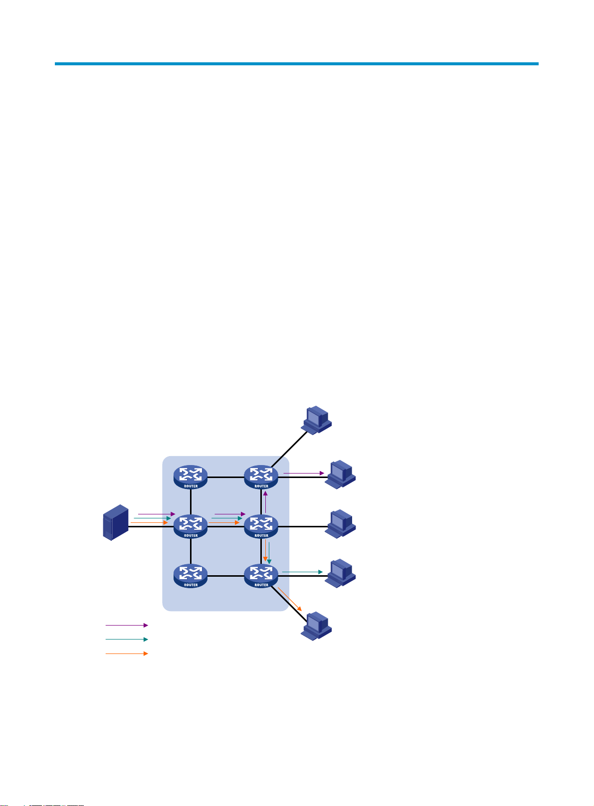
Multicast overview
Overview
As a technique that coexists with unicast and broadcast, the multicast technique effectively addresses the
issue of point-to-multipoint data transmission. By enabling high-efficiency point-to-multipoint data
transmission over a network, multicast greatly saves network bandwidth and reduces network load.
By using multicast technology, a network operator can easily provide new value-added services, such as
live webcasting, Web TV, distance learning, telemedicine, Web radio, real-time video conferencing, and
other bandwidth-critical and time-critical information services.
Unless otherwise stated, the term "multicast" in this document refers to IP multicast.
Multicast overview
The information transmission techniques include unicast, broadcast, and multicast.
Unicast
In unicast transmission, the information source must send a separate copy of information to each host that
needs the information.
Figure 1 Unicast transmission
Source
IP network
Packets for Host B
Packets for Host D
Packets for Host E
Host A
Receiver
Host B
Host C
Receiver
Host D
Receiver
Host E
In Figure 1, assume that Host B, Host D, and Host E need the information. A separate transmission
channel must be established from the information source to each of these hosts.
In unicast transmission, the traffic transmitted over the network is proportional to the number of hosts that
need the information. If a large number of hosts need the information, the information source must send
1
Page 14
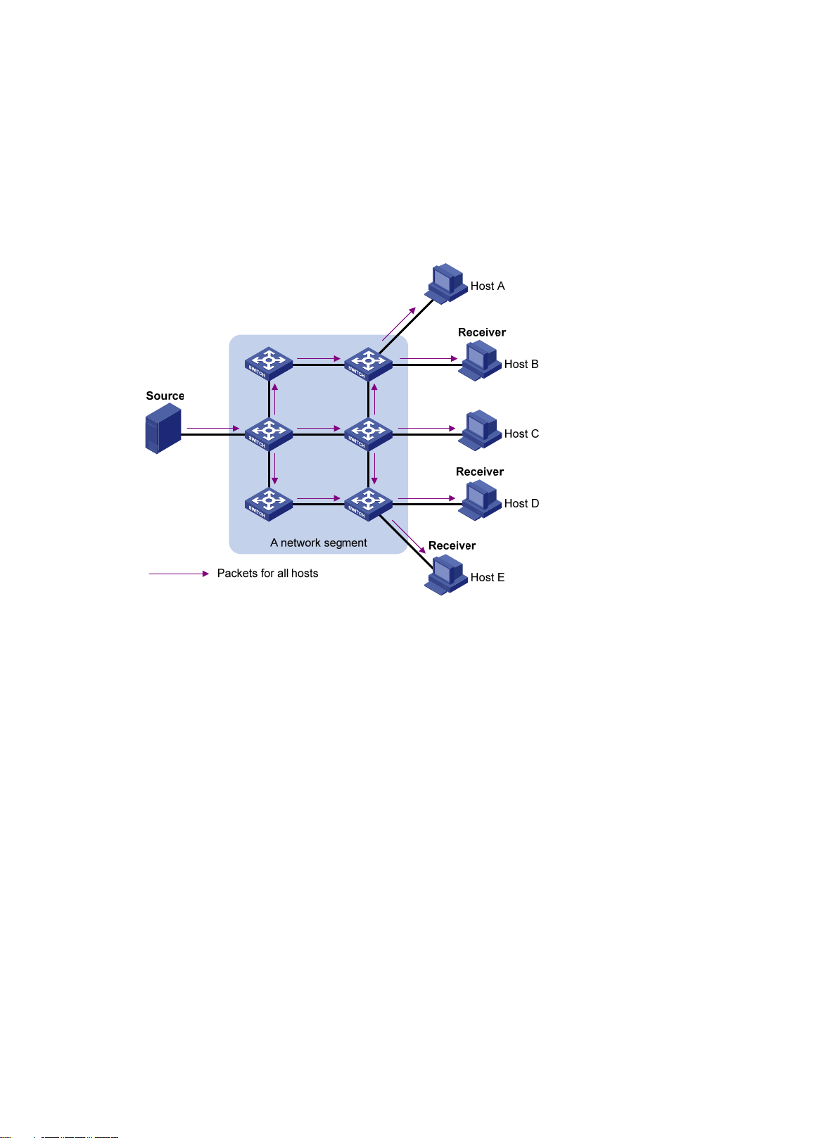
Broadcast
a separate copy of the same information to each of these hosts. Sending many copies can place a
tremendous pressure on the information source and the network bandwidth.
Unicast is not suitable for batch transmission of information.
In broadcast transmission, the information source sends information to all hosts on the subnet, even if
some hosts do not need the information.
Figure 2 Broadcast transmission
Multicast
In Figure 2, assume that only Host B, Host D, and Host E need the information. If the information is
broadcast to the subnet, Host A and Host C also receive it. In addition to information security issues,
broadcasting to hosts that do not need the information also causes traffic flooding on the same subnet.
Broadcast is disadvantageous in transmitting data to specific hosts. Moreover, broadcast transmission is
a significant waste of network resources.
Unicast and broadcast techniques cannot provide point-to-multipoint data transmissions with the
minimum network consumption.
Multicast transmission can solve this problem. When some hosts on the network need multicast
information, the information sender, or multicast source, sends only one copy of the information.
Multicast distribution trees are built through multicast routing protocols, and the packets are replicated
only on nodes where the trees branch.
2
Page 15
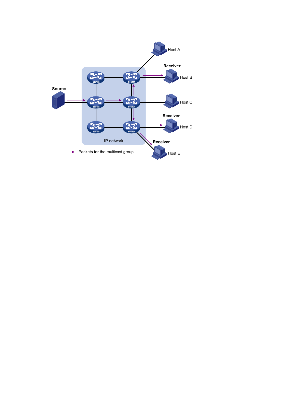
Figure 3 Multicast transmission
As shown in Figure 3, the multicast source sends only one copy of the information to a multicast group.
Host B, Host D, and Host E, which are receivers of the information, must join the multicast group. The
routers on the network duplicate and forward the information based on the distribution of the group
members. Finally, the information is correctly delivered to Host B, Host D, and Host E.
To summarize, multicast has the following advantages:
• Advantages over unicast—Because multicast traffic flows to the farthest-possible node from the
source before it is replicated and distributed, an increase in the number of hosts does not increase
the load of the source or the usage of network resources.
• Advantages over broadcast—Because multicast data is sent only to the receivers that need it,
multicast uses network bandwidth reasonably and enhances network security. In addition, data
broadcast is confined to the same subnet, but multicast is not.
Multicast features
Multicast transmission has the following features:
• A multicast group is a multicast receiver set identified by an IP multicast address. Hosts join a
multicast group to become members of the multicast group before they can receive the multicast
data addressed to that multicast group. Typically, a multicast source does not need to join a
multicast group.
• An information sender is called a "multicast source." A multicast source can send data to multiple
multicast groups at the same time, and multiple multicast sources can send data to the same
multicast group at the same time.
• All hosts that have joined a multicast group become members of the multicast group. The group
memberships are dynamic. Hosts can join or leave multicast groups at any time. Multicast groups
are not subject to geographic restrictions.
• Routers or Layer 3 switches that support Layer 3 multicast are called "multicast routers" or "Layer 3
multicast devices." In addition to providing the multicast routing function, a multicast router can also
3
Page 16

manage multicast group memberships on stub subnets with attached group members. A multicast
router itself can be a multicast group member.
For a better understanding of the multicast concept, you can compare multicast transmission to the
transmission of TV programs.
Table 1 Comparing TV program transmission and multicast transmission
TV transmission Multicast transmission
A TV station transmits a TV program through a
channel.
A user tunes the TV set to the channel. A receiver joins the multicast group.
The user starts to watch the TV program transmitted
by the TV station through the channel.
The user turns off the TV set or tunes to another
channel.
Common notations in multicast
The following notations are commonly used in multicast transmission:
• (*, G)—Rendezvous point tree (RPT), or a multicast packet that any multicast source sends to
multicast group G. Here, the asterisk (*) represents any multicast source, and "G" represents a
specific multicast group.
• (S, G)—Shortest path tree (SPT), or a multicast packet that multicast source S sends to multicast
group G. Here, "S" represents a specific multicast source, and "G" represents a specific multicast
group.
For more information about the concepts RPT and SPT, see "Configuring PIM" and "Configuring IPv6
PIM."
A multicast source sends multicast data to a multicast
group.
The receiver starts to receive the multicast data that the
source is sending to the multicast group.
The receiver leaves the multicast group or joins another
group.
Multicast advantages and applications
The multicast technique has the following advantages:
• Enhanced efficiency—Reduces the processor load of information source servers and network
devices.
• Optimal performance—Reduces redundant traffic.
• Distributed application—Enables point-to-multipoint applications at the price of minimum network
resources.
The multicast technique can be use for the following applications:
• Multimedia and streaming applications, such as web TV, web radio, and real-time video/audio
conferencing
• Communication for training and cooperative operations, such as distance learning and
telemedicine
• Data warehouse and financial applications (stock quotes)
• Any other point-to-multipoint application for data distribution
4
Page 17

Multicast models
Based on how the receivers treat the multicast sources, the multicast models include any-source multicast
(ASM), source-filtered multicast (SFM), and source-specific multicast (SSM).
• ASM model—In the ASM model, any sender can send information to a multicast group as a
multicast source, and receivers can join a multicast group (identified by a group address) and
obtain multicast information addressed to that multicast group. In this model, receivers do not know
the positions of the multicast sources in advance. However, they can join or leave the multicast
group at any time.
• SFM model—The SFM model is derived from the ASM model. To a sender, the two models appear
to have the same multicast membership architecture.
The SFM model functionally extends the ASM model. The upper-layer software checks the source
address of received multicast packets and permits or denies multicast traffic from specific sources.
Therefore, receivers can receive the multicast data from only part of the multicast sources. Because
not all multicast sources are valid to receivers, they are filtered.
• SSM model—Users might be interested in the multicast data from only certain multicast sources. The
SSM model provides a transmission service that enables users to specify the multicast sources that
they are interested in at the client side.
The main difference between the SSM model and the ASM model is that in the SSM model,
receivers have already determined the locations of the multicast sources by some other means. In
addition, the SSM model uses a multicast address range that is different from that of the ASM/SFM
model, and dedicated multicast forwarding paths are established between receivers and the
specified multicast sources.
Multicast architecture
IP multicast addresses the following issues:
• Where should the multicast source transmit information to? (Multicast addressing.)
• What receivers exist on the network? (Host registration.)
• Where is the multicast source that will provide data to the receivers? (Multicast source discovery.)
• How should information be transmitted to the receivers? (Multicast routing.)
IP multicast is an end-to-end service. The multicast architecture involves the following parts:
1. Addressing mechanism—A multicast source sends information to a group of receivers through a
multicast address.
2. Host registration—Receiver hosts can join and leave multicast groups dynamically. This
mechanism is the basis for management of group memberships.
3. Multicast routing—A multicast distribution tree (a forwarding path tree for multicast data on the
network) is constructed for delivering multicast data from a multicast source to receivers.
4. Multicast applications—A software system that supports multicast applications, such as video
conferencing, must be installed on multicast sources and receiver hosts. The TCP/IP stack must
support reception and transmission of multicast data.
5
Page 18

Multicast addresses
Network-layer multicast addresses (namely, multicast IP addresses) enables communication between
multicast sources and multicast group members. In addition, a technique must be available to map
multicast IP addresses to link-layer multicast MAC addresses.
The membership of a group is dynamic. Hosts can join or leave multicast groups at any time.
IP multicast addresses
• IPv4 multicast addresses:
The IANA assigns the Class D address space (224.0.0.0 to 239.255.255.255) for IPv4 multicast.
Table 2 Class D IP address blocks and description
Address block Description
224.0.0.0 to 224.0.0.255
224.0.1.0 to 238.255.255.255
Reserved permanent group addresses. The IP address 224.0.0.0 is
reserved. Other IP addresses can be used by routing protocols and
for topology searching, protocol maintenance, and so on. Table 3
ommon permanent group addresses. A packet destined for an
lists c
address in this block will not be forwarded beyond the local subnet
regardless of the TTL value in the IP header.
Globally scoped group addresses. This block includes the following
types of designated group addresses:
• 232.0.0.0/8—SSM group addresses.
• 233.0.0.0/8—Glop group addresses.
Administratively scoped multicast addresses. These addresses are
239.0.0.0 to 239.255.255.255
considered locally unique rather than globally unique, and can be
reused in domains administered by different organizations without
causing conflicts. For more information, see RFC 2365.
"Glop" is a mechanism for assigning multicast addresses between different ASs. By filling an AS
number into the middle two bytes of 233.0.0.0, you get 255 multicast addresses for that AS. For
more information, see RFC 2770.
Table 3 Some reserved multicast addresses
Address Description
224.0.0.1 All systems on this subnet, including hosts and routers.
224.0.0.2 All multicast routers on this subnet.
224.0.0.3 Unassigned.
224.0.0.4 DVMRP routers.
224.0.0.5 OSPF routers.
224.0.0.6 OSPF designated routers and backup designated routers.
224.0.0.7 ST routers.
224.0.0.8 ST hosts.
224.0.0.9 RIPv2 routers.
224.0.0.11 Mobile agents.
6
Page 19

Address Description
p
224.0.0.12 DHCP server/relay agent.
224.0.0.13 All PIM routers.
224.0.0.14 RSVP encapsulation.
224.0.0.15 All CBT routers.
224.0.0.16 SBM.
224.0.0.17 All SBMs.
224.0.0.18 VRRP.
• IPv6 multicast addresses:
Figure 4 IPv6 multicast format
The following describes the fields of an IPv6 multicast address, as shown in Figure 4:
{ 0xFF—Contains the most significant eight bits 11111111, which indicates that this address is an
IPv6 multicast address.
{ Flags—Contains four bits, as shown in Figure 5 and described in Table 4.
Figure 5 Flags field format
Table 4 Flags field description
Bit Descri
0 Reserved, set to 0.
tion
• When set to 0, it indicates that this address is an IPv6 multicast
R
address without an embedded RP address.
• When set to 1, it indicates that this address is an IPv6 multicast address
with an embedded RP address. (The P and T bits must also be set to 1.)
• When set to 0, it indicates that this address is an IPv6 multicast
P
address not based on a unicast prefix.
• When set to 1, it indicates that this address is an IPv6 multicast address
based on a unicast prefix. (The T bit must also be set to 1.)
• When set to 0, it indicates that this address is an IPv6 multicast
T
address permanently-assigned by IANA.
• When set to 1, it indicates that this address is a transient, or
dynamically assigned IPv6 multicast address.
7
Page 20
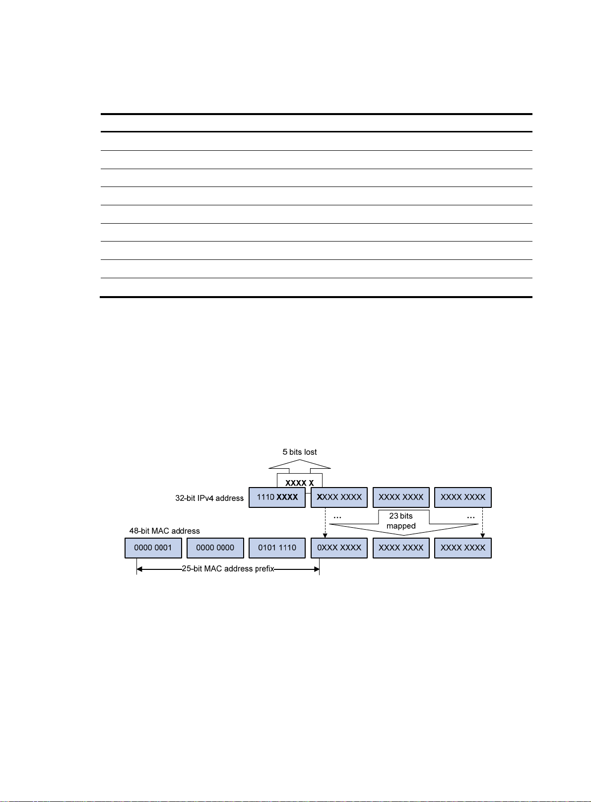
{ Scope—Contains four bits, which indicate the scope of the IPv6 internetwork for which the
g
multicast traffic is intended. Table 5 de
Table 5 Values of the Scope field
Value Meanin
0, F Reserved.
1 Interface-local scope.
2 Link-local scope.
3 Subnet-local scope.
4 Admin-local scope.
5 Site-local scope.
6, 7, 9 through D Unassigned.
8 Organization-local scope.
E Global scope.
{ Group ID—Contains 112 bits. It uniquely identifies an IPv6 multicast group in the scope that the
Scope field defines.
Ethernet multicast MAC addresses
scribes the values of the Scope field.
A multicast MAC address identifies a group of receivers at the data link layer.
• IPv4 multicast MAC addresses:
As defined by IANA, the most significant 24 bits of an IPv4 multicast MAC address are 0x01005E.
Bit 25 is 0, and the other 23 bits are the least significant 23 bits of a multicast IPv4 address.
Figure 6 IPv4-to-MAC address mapping
As shown in Figure 6, the most significant four bits of a multicast IPv4 address are 1110, which
means that this address is a multicast address. Only 23 bits of the remaining 28 bits are mapped
to a MAC address, so five bits of the multicast IPv4 address are lost. As a result, 32 multicast IPv4
addresses map to the same IPv4 multicast MAC address. Therefore, in Layer 2 multicast
forwarding, a switch might receive some multicast data destined for other IPv4 multicast groups.
The upper layer must filter such redundant data.
• IPv6 multicast MAC addresses:
As shown in Figure 7, the m
ost significant 16 bits of an IPv6 multicast MAC address are 0x3333.
The least significant 32 bits are the least significant 32 bits of a multicast IPv6 address.
8
Page 21

Figure 7 An example of IPv6-to-MAC address mapping
Multicast protocols
Multicast protocols include the following categories:
• Layer 3 and Layer 2 multicast protocols:
{ Layer 3 multicast refers to IP multicast working at the network layer.
Layer 3 multicast protocols—IGMP, MLD, PIM, IPv6 PIM, MSDP, MBGP, and IPv6 MBGP.
{ Layer 2 multicast refers to IP multicast working at the data link layer.
Layer 2 multicast protocols—IGMP snooping, MLD snooping, PIM snooping, IPv6 PIM
snooping, multicast VLAN, and IPv6 multicast VLAN.
• IPv4 and IPv6 multicast protocols:
{ For IPv4 networks—IGMP snooping, PIM snooping, multicast VLAN, IGMP, PIM, MSDP, and
MBGP.
{ For IPv6 networks—MLD snooping, IPv6 PIM snooping, IPv6 multicast VLAN, MLD, IPv6 PIM,
and IPv6 MBGP.
This section provides only general descriptions about applications and functions of the Layer 2 and Layer
3 multicast protocols in a network. For more information about these protocols, see the related chapters.
Layer 3 multicast protocols
Layer 3 multicast protocols include multicast group management protocols and multicast routing
protocols.
9
Page 22
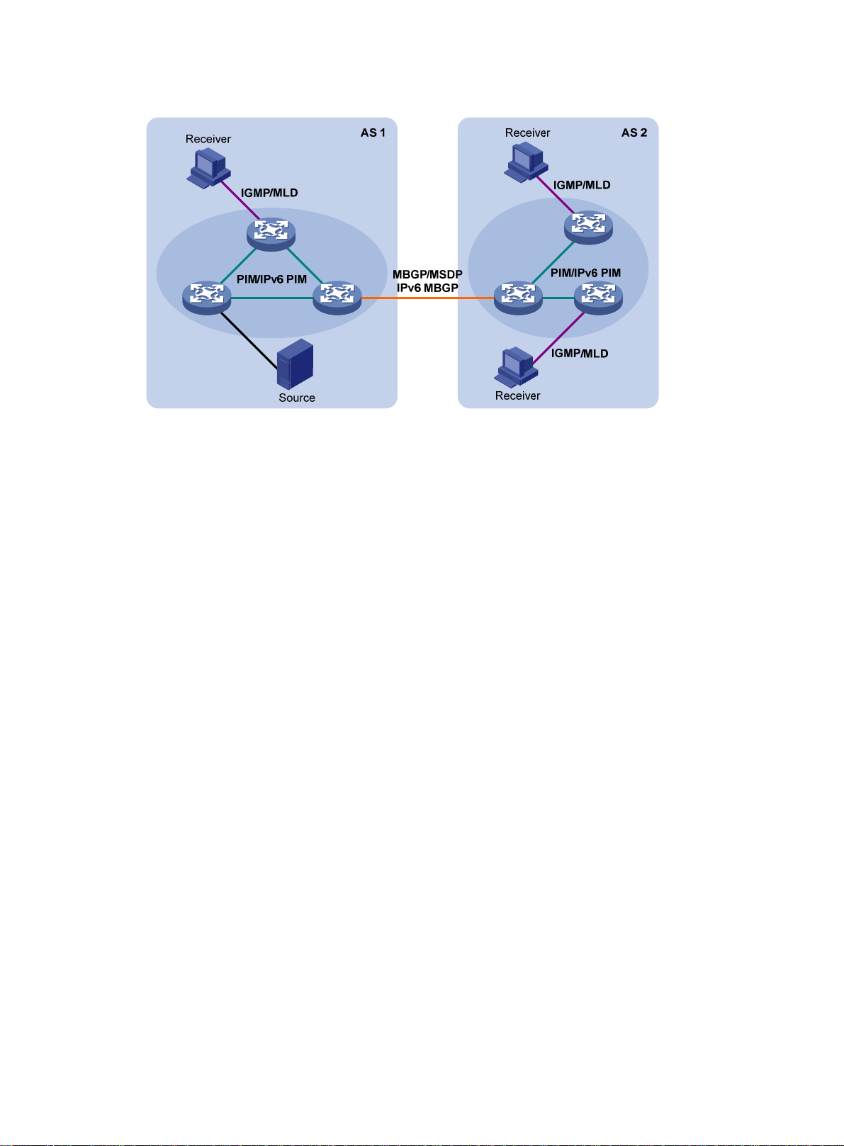
Figure 8 Positions of Layer 3 multicast protocols
• Multicast group management protocols:
Typically, the Internet Group Management Protocol (IGMP) or Multicast Listener Discovery (MLD)
protocol is used between hosts and Layer 3 multicast devices that directly connect to the hosts.
These protocols define the mechanism of establishing and maintaining group memberships
between hosts and Layer 3 multicast devices.
• Multicast routing protocols:
A multicast routing protocol runs on Layer 3 multicast devices to establish and maintain multicast
routes and forward multicast packets correctly and efficiently. Multicast routes constitute loop-free
data transmission paths (namely, a multicast distribution tree) from a data source to multiple
receivers.
In the ASM model, multicast routes include intra-domain routes and inter-domain routes.
{ An intra-domain multicast routing protocol discovers multicast sources and builds multicast
distribution trees within an AS to deliver multicast data to receivers. Among a variety of mature
intra-domain multicast routing protocols, Protocol Independent Multicast (PIM) is most widely
used. Based on the forwarding mechanism, PIM has dense mode (often referred to as
"PIM-DM") and sparse mode (often referred to as "PIM-SM").
{ An inter-domain multicast routing protocol is used for delivery of multicast information between
two ASs. So far, mature solutions include Multicast Source Discovery Protocol (MSDP) and
Multicast Border Gateway Protocol (MBGP). MSDP propagates multicast source information
among different ASs. MBGP is an extension of the Multiprotocol Border Gateway Protocol
(MP-BGP) for exchanging multicast routing information among different ASs.
For the SSM model, multicast routes are not divided into intra-domain routes and inter-domain
routes. Because receivers know the position of the multicast source, channels established through
PIM-SM are sufficient for the transport of multicast information.
Layer 2 multicast protocols
Layer 2 multicast protocols include IGMP snooping, MLD snooping, PIM snooping, and IPv6 PIM
snooping.
10
Page 23

Figure 9 Positions of Layer 2 multicast protocols
• IGMP snooping and MLD snooping:
IGMP snooping and MLD snooping are multicast constraining mechanisms that run on Layer 2
devices. They manage and control multicast groups by monitoring and analyzing IGMP or MLD
messages exchanged between the hosts and Layer 3 multicast devices, effectively controlling the
flooding of multicast data in a Layer 2 network.
• PIM snooping and IPv6 PIM snooping:
PIM snooping and IPv6 PIM snooping run on Layer 2 devices. They determine which ports are
interested in multicast data by analyzing the received IPv6 PIM messages, and add the ports to a
multicast forwarding entry to make sure multicast data can be forwarded to only the ports that are
interested in the data.
Multicast packet forwarding mechanism
In a multicast model, a multicast source sends information to the host group identified by the multicast
group address in the destination address field of IP multicast packets. To deliver multicast packets to
receivers located at different positions of the network, multicast routers on the forwarding paths usually
need to forward multicast packets that an incoming interface receives to multiple outgoing interfaces.
Compared with a unicast model, a multicast model is more complex in the following aspects:
• To ensure multicast packet transmission in the network, unicast routing tables or multicast routing
tables (for example, the MBGP routing table) specially provided for multicast must be used as
guidance for multicast forwarding.
• To process the same multicast information from different peers received on different interfaces of the
same device, every multicast packet undergoes a reverse path forwarding (RPF) check on the
incoming interface. The result of the RPF check determines whether the packet will be forwarded or
discarded. The RPF check mechanism is the basis for most multicast routing protocols to implement
multicast forwarding.
For more information about the RPF mechanism, see "Configuring multicast routing and forwarding" and
"Configuring IPv6 multicast routing and forwarding."
11
Page 24
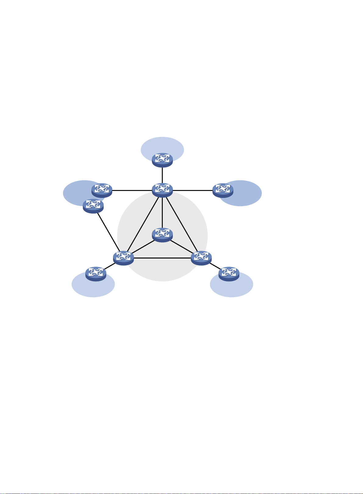
Multicast support for VPNs
Multicast support for VPNs refers to multicast applied in VPNs.
Multicast support for VPNs is not available in IPv6 networks.
Introduction to VPN instances
VPNs must be isolated from one another and from the public network. As shown in Figure 10, VPN A and
VPN B separately access the public network through PE devices.
Figure 10 VPN networking diagram
VPN A
CE a2
CE b1
CE a1
VPN A
CE b2
PE 1
PE 2
P
Public network
CE b3
VPN BVPN B
CE a3
PE 3
VPN A
• The provider (P) device belongs to the public network. The customer edge (CE) devices belong to
their respective VPNs. Each CE device serves its own VPN and maintains only one set of forwarding
mechanisms.
• The provider edge (PE) devices connect to the public network and the VPNs. Each PE device must
strictly distinguish the information for different networks, and maintain a separate forwarding
mechanism for each network. On a PE device, a set of software and hardware that serve the same
network forms an instance. Multiple instances can exist on the same PE device, and an instance can
reside on different PE devices. On a PE device, the instance for the public network is called the
public network instance, and those for VPNs are called VPN instances.
Multicast application in VPNs
A PE device that supports multicast for VPNs does the following operations:
• Maintains an independent set of multicast forwarding mechanisms for each VPN, including the
multicast protocols, PIM neighbor information, and multicast routing table. In a VPN, the device
forwards multicast data based on the forwarding table or routing table for that VPN.
• Implements the isolation between different VPNs.
12
Page 25

• Implements information exchange and data conversion between the public network and VPN
instances.
As shown in Figure 10, w
hen a multicast source in VPN A sends a multicast stream to a multicast group,
only the receivers that belong to both the multicast group and VPN A can receive the multicast stream.
The multicast data is multicast both in VPN A and on the public network.
13
Page 26

Configuring IGMP
Overview
As a TCP/IP protocol responsible for IP multicast group member management, the IGMP is used by IP
hosts and adjacent multicast routers to establish and maintain their multicast group memberships.
IGMP versions
• IGMPv1 (documented in RFC 1112 )
• IGMPv2 (documented in RFC 2236)
• IGMPv3 (documented in RFC 3376)
All IGMP versions support the ASM model. In addition to the ASM model, IGMPv3 can directly
implement the SSM model. IGMPv1 and IGMPv2 must work with the IGMP SSM mapping function to
implement the SSM model. For more information about the ASM and SSM models, see "Multicast
overview."
IGMPv1 overview
IGMPv1 manages multicast group memberships based on the query and response mechanism.
All multicast routers on the same subnet can get IGMP membership report messages (often called
"reports") from hosts, but the subnet needs only one router to act as the IGMP querier to send IGMP
query messages (often called "queries"). The querier election mechanism determines which router acts
as the IGMP querier on the subnet.
In IGMPv1, the designated router (DR) elected by the working multicast routing protocol (such as PIM)
serves as the IGMP querier. For more information about DR, see "Configuring PIM."
14
Page 27
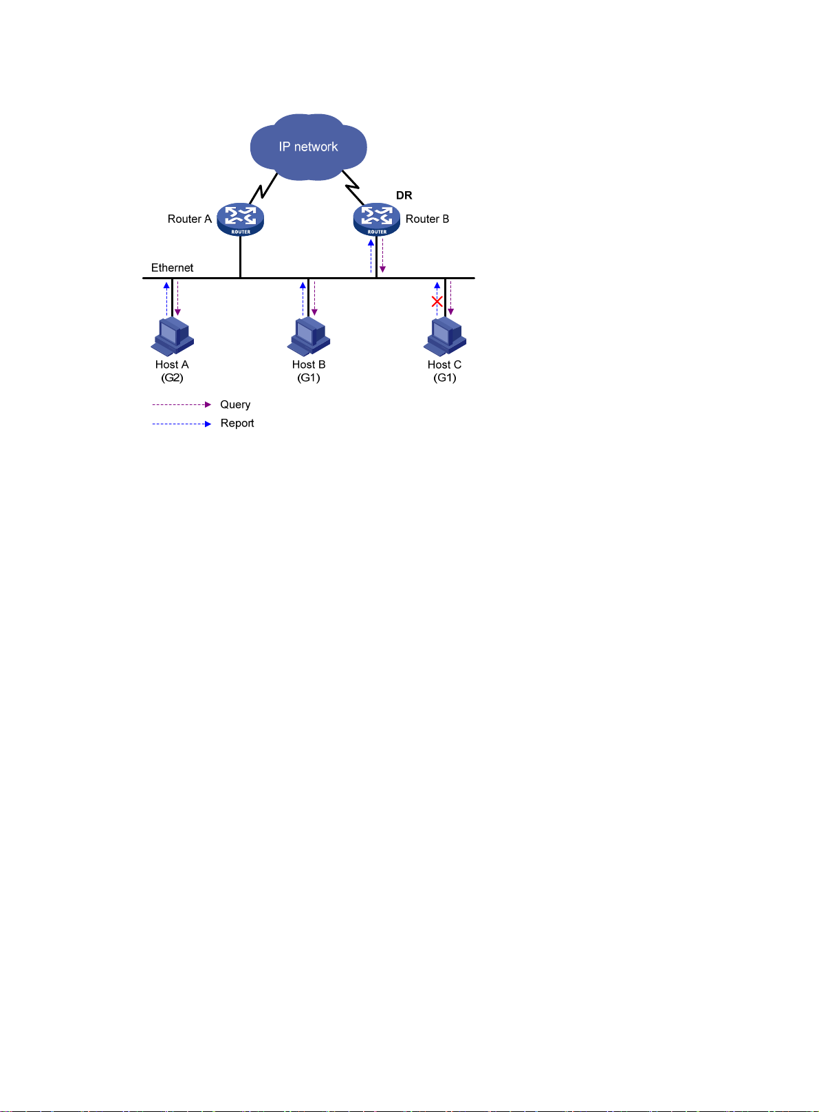
Figure 11 IGMP queries and reports
As shown in Figure 11, assume that Host B and Host C are interested in multicast data addressed to
multicast group G1, and Host A is interested in multicast data addressed to G2. The following process
describes how the hosts join the multicast groups and how the IGMP querier (Router B in the figure)
maintains the multicast group memberships:
1. The hosts send unsolicited IGMP reports to the addresses of the multicast groups that they want to
join, without having to wait for the IGMP queries from the IGMP querier.
2. The IGMP querier periodically multicasts IGMP queries (with the destination address of 224.0.0.1)
to all hosts and routers on the local subnet.
3. After receiving a query message, Host B or Host C (the delay timer of whichever expires first) sends
an IGMP report to the multicast group address of G1, to announce its membership for G1. Assume
that Host B sends the report message. After receiving the report from Host B, Host C (which is on
the same subnet as Host B) suppresses its own report for G1, because the IGMP routers (Router A
and Router B) have already known that at least one host on the local subnet is interested in G1. This
IGMP report suppression mechanism helps reduce traffic on the local subnet.
4. At the same time, because Host A is interested in G2, it sends a report to the multicast group
address of G2.
5. Through the query/report process, the IGMP routers determine that members of G1 and G2 are
attached to the local subnet, and the multicast routing protocol (PIM, for example) that is running
on the routers generates (*, G1) and (*, G2) multicast forwarding entries. These entries will be the
basis for subsequent multicast forwarding, where asterisk represents any multicast source.
6. When the multicast data addressed to G1 or G2 reaches an IGMP router, because the (*, G1) and
(*, G2) multicast forwarding entries exist on the IGMP router, the router forwards the multicast
data to the local subnet, and then the receivers on the subnet receive the data.
IGMPv1 does not specifically define a leave group message (often called a "leave message.") When an
IGMPv1 host is leaving a multicast group, it stops sending reports to the address of the multicast group
that it listened to. If no member exists in a multicast group on the subnet, the IGMP router will not receive
any report addressed to that multicast group. In this case, the router will delete the multicast forwarding
entries for that multicast group after a period of time.
15
Page 28

IGMPv2 overview
Compared with IGMPv1, IGMPv2 has introduced a querier election mechanism and a leave-group
mechanism.
Querier election mechanism
In IGMPv1, the DR elected by the Layer 3 multicast routing protocol (such as PIM) serves as the querier
among multiple routers on the same subnet.
IGMPv2 introduced an independent querier election mechanism. The querier election process is as
follows:
1. Initially, every IGMPv2 router assumes itself as the querier and sends IGMP general query
messages (often called "general queries") to all hosts and routers on the local subnet. The
destination address is 224.0.0.1.
2. After receiving a general query, every IGMPv2 router compares the source IP address of the query
message with its own interface address. After comparison, the router with the lowest IP address
wins the querier election and all other IGMPv2 routers become non-queriers.
3. All the non-queriers start a timer, known as "other querier present timer". If a router receives an
IGMP query from the querier before the timer expires, it resets this timer. Otherwise, it assumes the
querier to have timed out and initiates a new querier election process.
"Leave group" mechanism
In IGMPv1, when a host leaves a multicast group, it does not send any notification to the multicast router.
The multicast router relies on the host response timeout timer to determine whether a group has members.
This adds to the leave latency.
In IGMPv2, when a host leaves a multicast group, the following steps occur:
1. This host sends a leave message to all routers on the local subnet. The destination address is
224.0.0.2.
2. After receiving the leave message, the querier sends a configurable number of group-specific
queries to the group that the host is leaving. The destination address field and group address field
of the message are both filled with the address of the multicast group that is being queried.
3. One of the remaining members (if any on the subnet) of the group that is being queried should
send a membership report within the maximum response time set in the query messages.
4. If the querier receives a membership report for the group within the maximum response time, it will
maintain the memberships of the group. Otherwise, the querier will assume that no hosts on the
subnet are still interested in multicast traffic to that group and will stop maintaining the
memberships of the group.
IGMPv3 overview
IGMPv3 is based on and is compatible with IGMPv1 and IGMPv2. It provides hosts with enhanced
control capabilities and provides enhancements of query and report messages.
Enhancements in control capability of hosts
IGMPv3 introduced two source filtering modes (Include and Exclude). These modes allow a host to join
a designated multicast group and to choose whether to receive or reject multicast data from a designated
multicast source. When a host joins a multicast group, one of the following occurs:
• If it expects to receive multicast data from specific sources like S1, S2, …, it sends a report with the
Filter-Mode denoted as "Include Sources (S1, S2, …)."
16
Page 29
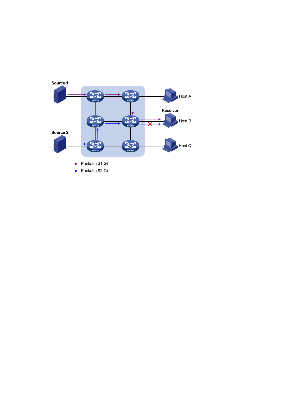
• If it expects to reject multicast data from specific sources like S1, S2, …, it sends a report with the
Filter-Mode denoted as "Exclude Sources (S1, S2, …)."
As shown in Figure 12,
the network comprises two multicast sources, Source 1 (S1) and Source 2 (S2),
both of which can send multicast data to multicast group G. Host B is interested in the multicast data that
Source 1 sends to G but not in the data from Source 2.
Figure 12 Flow paths of source-and-group-specific multicast traffic
In IGMPv1 or IGMPv2, Host B cannot select multicast sources when it joins multicast group G. Therefore,
multicast streams from both Source 1 and Source 2 will flow to Host B whether or not it needs them.
When IGMPv3 runs between the hosts and routers, Host B can explicitly express that it needs to receive
the multicast data that Source 1 sends to multicast group G (denoted as (S1, G)), rather than the multicast
data that Source 2 sends to multicast group G (denoted as (S2, G)). Only multicast data from Source 1
is delivered to Host B.
Enhancements in query and report capabilities
1. Query message carrying the source addresses:
IGMPv3 supports not only general queries (feature of IGMPv1) and group-specific queries (feature
of IGMPv2), but also group-and-source-specific queries.
{ A general query does not carry a group address or a source address.
{ A group-specific query carries a group address, but no source address.
{ A group-and-source-specific query carries a group address and one or more source addresses.
2. Reports containing multiple group records:
Unlike an IGMPv1 or IGMPv2 report message, an IGMPv3 report message is destined to
224.0.0.22 and contains one or more group records. Each group record contains a multicast
group address and a multicast source address list.
Group records include the following categories:
{ IS_IN—The source filtering mode is Include. The report sender requests the multicast data from
only the sources defined in the specified multicast source list.
{ IS_EX—The source filtering mode is Exclude. The report sender requests the multicast data from
any sources but those defined in the specified multicast source list.
{ TO_IN—The filtering mode has changed from Exclude to Include.
{ TO_EX—The filtering mode has changed from Include to Exclude.
17
Page 30
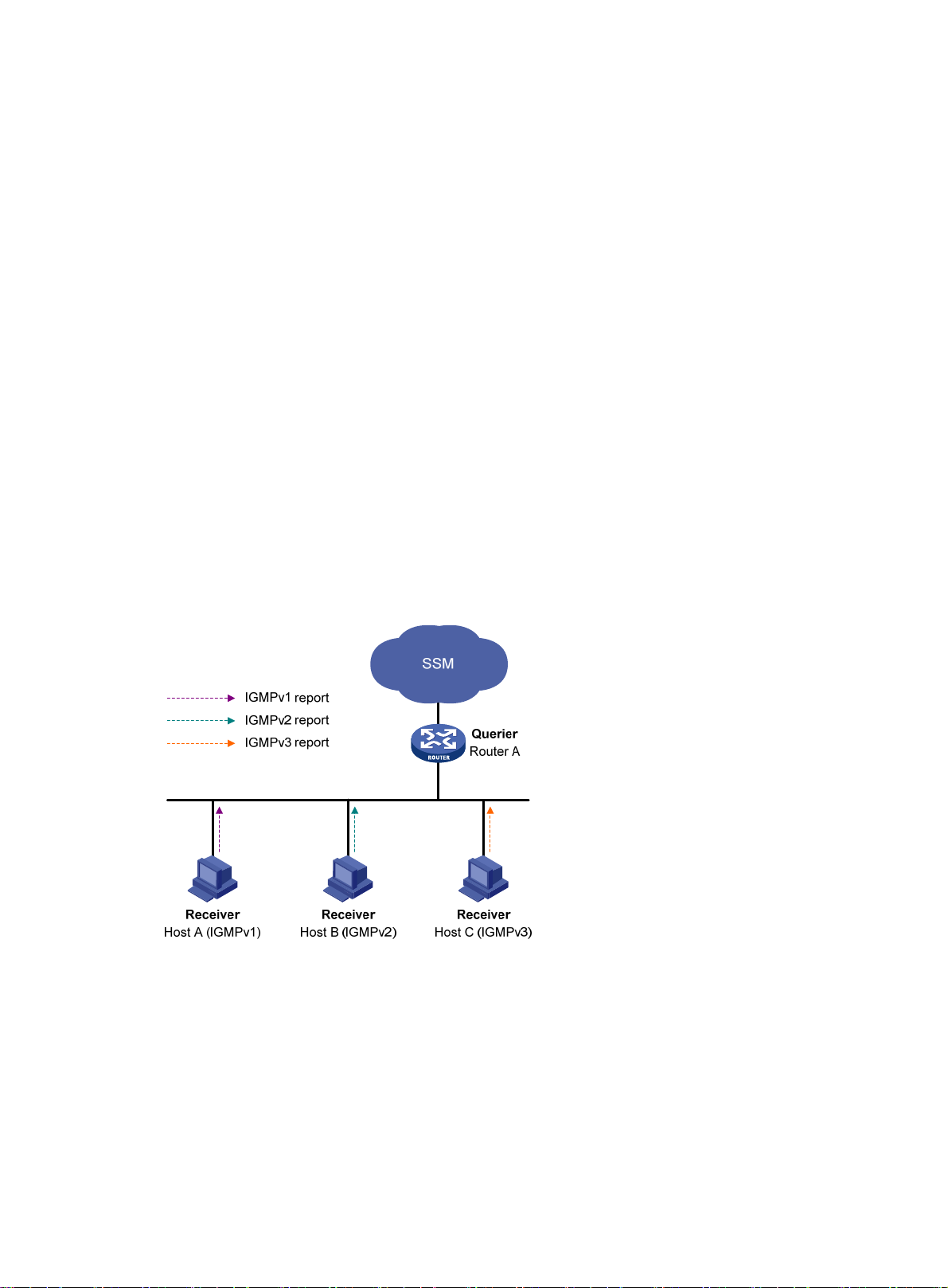
{ ALLOW—The Source Address fields in this group record contain a list of the additional sources
that the system wants to obtain data from, for packets sent to the specified multicast address. If
the change was to an Include source list, these sources are the addresses that were added to the
list. If the change was to an Exclude source list, these sources are the addresses that were
deleted from the list.
{ BLOCK—The Source Address fields in this group record contain a list of the sources that the
system no longer wants to obtain data from, for packets sent to the specified multicast address.
If the change was to an Include source list, these sources are the addresses that were deleted
from the list. If the change was to an Exclude source list, these sources are the addresses that
were added to the list.
IGMP SSM mapping
The IGMP SSM mapping feature enables you to configure static IGMP SSM mappings on the last-hop
router to provide SSM support for receiver hosts that are running IGMPv1 or IGMPv2. The SSM model
assumes that the last-hop router has identified the desired multicast sources when receivers join multicast
groups.
• When a host that is running IGMPv3 joins a multicast group, it can explicitly specify one or more
multicast sources in its IGMPv3 report.
• A host that is running IGM Pv1 or I GMPv2, however, cannot specify multicast source addresses in its
report. In this case, you must configure the IGMP SSM mapping feature to translate the (*, G)
information in the IGMPv1 or IGMPv2 report into (G, INCLUDE, (S1, S2...)) information.
Figure 13 IGMP SSM mapping
As shown in Figure 13, on an SSM network, Host A, Host B, and Host C run IGMPv1, IGMPv2, and
IGMPv3, respectively. To provide SSM service for all the hosts if IGMPv3 is not available on Host A and
Host B, you must configure the IGMP SSM mapping feature on Router A.
With the IGMP SSM mapping feat ure configu red, when Router A rec eives an IGMP v1 or IGM Pv2 repor t,
it checks the multicast group address G carried in the message and does the following:
• If G is not in the SSM group range, Router A cannot provide the SSM service but can provide the
ASM service.
• If G is in the SSM group range but no IGMP SSM mappings that correspond to the multicast group
G have bee n co nfig ured on Ro uter A, Ro uter A cannot provide SSM service and drops the message.
18
Page 31

• If G is in the SSM group range and the IGMP SSM mappings have been configured on Router A for
multicast group G, Router A translates the (*, G) information in the IGMP report into (G, INCLUDE,
(S1, S2...)) information based on the configured IGMP SSM mappings and provides SSM service
accordingly.
NOTE:
The IGMP SSM mapping feature does not process IGMPv3 reports.
For more information about the SSM group range, see "Configuring PIM."
IGMP proxying
In a simple tree-shaped topology, it is not necessary to configure complex multicast routing protocols,
such as PIM, on edge devices. Instead, you can configure IGMP proxying on these devices. With IGMP
proxying configured, the device serves as a proxy for the downstream hosts to send IGMP messages,
maintain group memberships, and implement multicast forwarding based on the memberships. In this
case, each boundary device is a host but no longer a PIM neighbor to the upstream device.
Figure 14 IGMP proxying
As shown in Figure 14, an IGMP proxy device has the following types of interfaces:
• Upstream interface—Also called the "proxy interface." A proxy interface is an interface on which
IGMP proxying is configured. It is in the direction toward the root of the multicast forwarding tree.
An upstream interface acts as a host that is running IGMP. Therefore, it is also called the "host
interface."
• Downstream interface—An interface that is running IGMP and is not in the direction toward the
root of the multicast forwarding tree. A downstream interface acts as a router that is running IGMP.
Therefore, it is also called the "router interface."
An IGMP proxy device maintains a group membership database, which stores the group memberships
on all the downstream interfaces. Each entry comprises the multicast address, filter mode, and source list.
Such an entry is a collection of members in the same multicast group on each downstream interface.
19
Page 32

An IGMP proxy device performs host functions on the upstream interface based on the database. It
responds to queries according to the information in the database or sends join/leave messages when the
database changes. On the other hand, the IGMP proxy device performs router functions on the
downstream interfaces by participating in the querier election, sending queries, and maintaining
memberships based on the reports.
IGMP support for VPNs
IGMP maintains group memberships on a per-interface base. After receiving an IGMP message on an
interface, IGMP processes the packet within the VPN that the interface belongs to. If IGMP that runs in a
VPN needs to exchange information with another multicast protocol, it passes the information only to the
protocol that runs in this VPN.
Protocols and standards
• RFC 1112, Host Extensions for IP Multicasting
• RFC 2236, Internet Group Management Protocol, Version 2
• RFC 3376, Internet Group Management Protocol, Version 3
• RFC 4605, Internet Group Management Protocol (IGMP)/Multicast Listener Discovery (MLD)-Based
Multicast Forwarding ("IGMP/MLD Proxying")
IGMP configuration task list
For the configuration tasks in this section, the following rules apply:
• The configurations made in IGMP view are effective on all interfaces. The configurations made in
interface view are effective only on the current interface.
• A configuration made in interface view always has priority over the same global configuration in
IGMP view. If you do not make the configuration in interface view, the corresponding global
configuration made in IGMP view applies to the interface.
Complete these tasks to configure IGMP:
Task Remarks
Enabling IGMP Required.
Specifying the IGMP version Optional.
Configuring basic IGMP
functions
Adjusting IGMP performance
Configuring an interface as a static member interface Optional.
Configuring a multicast group filter Optional.
Setting the maximum number of multicast groups that an
interface can join
Configuring Router-Alert option handling methods Optional.
Configuring IGMP query and response parameters Optional.
Enabling IGMP fast-leave processing Optional.
Optional.
Configuring IGMP SSM
mapping
Enabling the IGMP host tracking function Optional.
Enabling SSM mapping Optional.
Configuring SSM mappings Optional.
20
Page 33

Task Remarks
Enabling IGMP proxying Optional.
Configuring IGMP proxying
Configuring multicast forwarding on a downstream
interface
Configuring basic IGMP functions
This section describes how to configure basic IGMP functions.
Configuration prerequisites
Before you configure basic IGMP functions, complete the following tasks:
• Configure any unicast routing protocol so that all devices in the domain are interoperable at the
network layer.
• Configure PIM-DM or PIM-SM.
• Determine the IGMP version.
• Determine the multicast group and multicast source addresses for static group member
configuration.
Optional.
• Determine the ACL rule for multicast group filtering.
• Determine the maximum number of multicast groups that an interface can join.
Enabling IGMP
To configure IGMP, you must enable IGMP on the interface where the multicast group memberships will
be established and maintained.
Enabling IGMP for the public network
Step Command Remarks
1. Enter system view.
2. Enable IP multicast routing.
3. Enter interface view.
4. Enable IGMP.
Enabling IGMP for a VPN instance
Step Command Remarks
5. Enter system view.
6. Create a VPN instance and
enter its view.
system-view N/A
multicast routing-enable Disabled by default.
interface interface-type
interface-number
igmp enable Disabled by default.
system-view N/A
ip vpn-instance vpn-instance-name
N/A
N/A
7. Configure an RD for the VPN
instance.
8. Enable IP multicast routing.
route-distinguisher
route-distinguisher
multicast routing-enable Disabled by default.
21
No RD is configured by default.
Page 34

Step Command Remarks
9. Enter interface view.
10. Bind the interface with the
VPN instance.
11. Enable IGMP.
interface interface-type
interface-number
ip binding vpn-instance
vpn-instance-name
igmp enable Disabled by default.
For more information about the ip vpn-instance, route-distinguisher, and ip binding vpn-instance
commands, see MPLS Command Reference.
Specifying the IGMP version
Because the protocol packets of different IGMP versions vary in structure and type, you must specify the
same IGMP version for all routers on the same subnet. Otherwise, IGMP cannot work correctly.
Specifying the global version of IGMP
Step Command Remarks
1. Enter system view.
2. Enter public network IGMP view or
VPN instance IGMP view.
system-view N/A
igmp [ vpn-instance
vpn-instance-name ]
N/A
By default, an interface belongs to
the public network, and is not
bound with any VPN instance.
N/A
3. Specify the global version of IGMP.
version version-number IGMPv2 by default.
Specifying the version of IGMP on an interface
Step Command Remarks
1. Enter system view.
2. Enter interface view.
3. Specify the version of IGMP
on the interface.
system-view N/A
interface interface-type
interface-number
igmp version version-number IGMPv2 by default.
N/A
Configuring an interface as a static member interface
You can configure an interface as a static member of a multicast group or a multicast source and group,
so that the interface can receive multicast data addressed to that multicast group for the purpose of
testing multicast data forwarding.
Configuration guidelines
• When you configure an interface on a PIM-SM device as a static member interface, if the interface
is PIM-SM enabled, the interface must be a PIM-SM DR. If the interface is IGMP enabled but not
PIM-SM enabled, it must be an IGMP querier. For more information about PIM-SM and a DR, see
"Configuring PIM."
• A static member interface does not respond to queries that the IGMP querier sends. When you
configure an interface as a static member or cancel this configuration on the interface, the interface
22
Page 35

does not unsolicitedly send any IGMP report or IGMP leave message. In other words, the interface
is not a real member of the multicast group or the multicast source and group.
Configuration procedure
To configure an interface as a static member interface:
Step Command Remarks
1. Enter system view.
system-view N/A
2. Enter interface view.
3. Configure the interface as a
static member interface.
interface interface-type
interface-number
igmp static-group group-address
[ source source-address ]
Configuring a multicast group filter
To restrict the hosts on the network attached to an interface from joining certain multicast groups, you can
set an ACL rule on the interface as a packet filter. In this way, the interface maintains only the multicast
groups that match the criteria.
To configure a multicast group filter:
Step Command Remarks
1. Enter system view.
2. Enter interface view.
3. Configure a multicast group
filter.
system-view N/A
interface interface-type
interface-number
igmp group-policy acl-number
[ version-number ]
N/A
An interface is not a static member
of any multicast group or multicast
source and group by default.
N/A
By default, no multicast group filter
is configured on this interface.
Namely, hosts on the current
interface can join any valid
multicast group. .
Setting the maximum number of multicast groups that an interface can join
This configuration only limits the number of multicast groups that are dynamically joined.
To configure the maximum number of multicast groups an interface can join:
Step Command
1. Enter system view.
2. Enter interface view.
3. Configure the maximum
number of multicast groups
that the interface can join.
system-view N/A
interface interface-type
interface-number
igmp group-limit limit
23
Remarks
N/A
The default value varies by device model.
For more information, see IP Multicast
Command Reference.
Page 36

Adjusting IGMP performance
When you adjust IGMP performance, follow these guidelines:
• The configurations made in IGMP view are effective on all interfaces. The configurations made in
interface view are effective only on the current interface.
• A configuration made in interface view always takes priority over the same configuration made in
IGMP view, regardless of the configuration sequence.
Configuration prerequisites
Before adjusting IGMP performance, complete the following tasks:
• Configure any unicast routing protocol so that all devices in the domain are interoperable at the
network layer.
• Configure basic IGMP functions.
• Determine the startup query interval.
• Determine the startup query count.
• Determine the IGMP general query interval.
• Determine the IGMP querier's robustness variable.
• Determine the maximum response time for IGMP general queries.
• Determine the IGMP last-member query interval.
• Determine the other querier present interval.
Configuring Router-Alert option handling methods
IGMP queries include group-specific queries and group-and-source-specific queries. Multicast groups
change dynamically, so a device cannot maintain the information for all multicast sources and groups.
For this reason, when an IGMP router receives a multicast packet but cannot locate the outgoing interface
for the destination multicast group, it must use the Router-Alert option to pass the multicast packet to the
upper-layer protocol for processing. For more information about the Router-Alert option, see RFC 2113 .
An IGMP message is processed differently depending on whether it carries the Router-Alert option in the
IP header:
• For compatibility, the device by default ignores the Router-Alert option and processes all received
IGMP messages, no matter whether the IGMP messages carry the Router-Alert option.
• To enhance device performance, avoid unnecessary costs, and ensure protocol security, configure
the device to discard IGMP messages that do not carry the Router-Alert option.
Configuring Router-Alert option handling methods globally
Step Command Remarks
1. Enter system view.
2. Enter public network IGMP
view or VPN instance IGMP
view.
system-view N/A
igmp [ vpn-instance
vpn-instance-name ]
N/A
24
Page 37

Step Command Remarks
3. Configure the router to
discard any IGMP message
that does not carry the
Router-Alert option.
4. Enable insertion of the
Router-Alert option into IGMP
messages.
require-router-alert
send-router-alert
Configuring Router-Alert option handling methods on an interface
Step Command Remarks
1. Enter system view.
system-view N/A
By default, the device does not
check the Router-Alert option.
By default, IGMP messages carry
the Router-Alert option.
2. Enter interface view.
3. Configure the interface to
discard any IGMP message
that does not carry the
Router-Alert option.
4. Enable insertion of the
Router-Alert option into IGMP
messages.
interface interface-type
interface-number
igmp require-router-alert
igmp send-router-alert
N/A
By default, the device does not
check the Router-Alert option.
By default, IGMP messages carry
the Router-Alert option.
Configuring IGMP query and response parameters
On startup, the IGMP querier sends IGMP general queries at the startup query interval, which is
one-quarter of the IGMP general query interval. The number of queries, or the startup query count, is user
configurable.
After startup, the IGMP querier periodically sends IGMP general queries at the IGMP general query
interval to check for multicast group members on the network. You can modify the IGMP general query
interval based on actual condition of the network.
The IGMPv2 querier sends IGMP group-specific queries at the IGMP last-member query interval when it
receives an IGMP leave message. The IGMPv3 querier sends IGMP group-and-source-specific queries at
the IGMP last-member query interval when it receives a multicast group and multicast mapping change
report. The number of queries, or the last-member query count, equals the robustness variable—the
maximum number of packet retransmissions.
A multicast listening host starts a delay timer for each multicast group it has joined when it receives an
IGMP query (general query, group-specific query, or group-and-source-specific query). The timer is
initialized to a random value in the range of 0 to the maximum response tim e derived i n the IGMP query.
When the timer value decreases to 0, the host sends an IGMP report to the corresponding multicast
group.
To speed up the response of hosts to IGMP queries and avoid simultaneous timer expirations causing
IGMP report traffic bursts, you must correctly set the maximum response time.
• For IGMP general queries, the maximum response time is set by the max-response-time command.
• For IGMP group-specific queries and IGMP group-and-source-specific queries, the maximum
response time equals the IGMP last-member query interval.
25
Page 38

When multiple multicast routers exist on the same subnet, the IGMP querier is responsible for sending
IGMP queries. If a non-querier router receives no IGMP query from the querier when the other querier
present interval expires, it considers that the querier as having failed and starts a new querier election.
Otherwise, the non-querier router resets the other querier present timer.
Configuration guidelines
• To avoid frequent IGMP querier changes, set the other querier present interval greater than the
IGMP general query interval.
• To avoid incorrect multicast group member removals, set the IGMP general query interval greater
than the maximum response time for IGMP general queries.
• The configurations of the maximum response time for IGMP general queries, the IGMP last member
query interval and the IGMP other querier present interval are effective only for IGMPv2 and
IGMPv3.
Configuring IGMP query and response parameters globally
Step Command Remarks
1. Enter system view.
2. Enter public network IGMP
view or VPN instance IGMP
view.
system-view N/A
igmp [ vpn-instance
vpn-instance-name ]
N/A
3. Configure the IGMP querier's
robustness variable.
4. Configure the startup query
interval.
5. Configure the startup query
count.
6. Configure the IGMP general
query interval.
7. Configure the maximum
response time for IGMP
general queries.
8. Configure the IGMP
last-member query interval.
9. Configure the other querier
present interval.
robust-count robust-value
startup-query-interval interval
startup-query-count value
timer query interval
max-response-time interval
last-member-query-interval
interval
timer other-querier-present
interval
2 by default.
A higher robustness variable
makes the IGMP querier more
robust, but results in longer
multicast group timeout time.
By default, the startup query
interval is one-quarter of the "IGMP
general query interval."
By default, the startup query count
is the same as the IGMP querier's
robustness variable.
60 seconds by default.
10 seconds by default.
1 second by default.
By default, the other querier
present interval is [ IGMP general
query interval ] × [ IGMP
robustness variable ] + [ maximum
response time for IGMP general
queries ] / 2.
26
Page 39

Configuring IGMP query and response parameters on an interface
Step Command Remarks
1. Enter system view.
system-view N/A
2. Enter interface view.
3. Configure the IGMP querier's
robustness variable.
4. Configure the startup query
interval.
5. Configure the startup query
count.
6. Configure the IGMP general
query interval.
7. Configure the maximum
response time for IGMP
general queries.
8. Configure the IGMP last
member query interval.
9. Configure the other querier
present interval.
interface interface-type
interface-number
igmp robust-count robust-value
igmp startup-query-interval
interval
igmp startup-query-count value
igmp timer query interval
igmp max-response-time interval 10 seconds by default.
igmp last-member-query-interval
interval
igmp timer other-querier-present
interval
N/A
2 by default.
A higher robustness variable
makes the IGMP querier more
robust, but results in longer
multicast group timeout time.
By default, the startup query
interval is one-quarter of the "IGMP
general query interval."
By default, the startup query count
is the same as the IGMP querier's
robustness variable.
60 seconds by default.
1 second by default.
By default, the other querier
present interval is [ IGMP general
query interval ] × [ IGMP
robustness variable ] + [ maximum
response time for IGMP general
queries ] / 2.
Enabling IGMP fast-leave processing
In some applications, such as ADSL dial-up networking, only one multicast receiver host is attached to a
port of the IGMP querier. To allow fast response to the leave messages of the host when it switches
frequently from one multicast group to another, you can enable IGMP fast-leave processing on the IGMP
querier.
With fast-leave processing enabled, after receiving an IGMP leave message from a host, the IGMP
querier directly sends a leave notification to the upstream without sending IGMP group-specific queries
or IGMP group-and-source-specific queries. Thus, the leave latency is reduced on one hand, and the
network bandwidth is saved on the other hand.
The IGMP fast-leave processing configuration is effective only if the device is running IGMPv2 or
IGMPv3.
Enabling IGMP fast-leave processing globally
Step Command Remarks
1. Enter system view.
system-view N/A
27
Page 40

Step Command Remarks
2. Enter public network IGMP
view or VPN instance IGMP
view.
igmp [ vpn-instance
vpn-instance-name ]
N/A
3. Enable IGMP fast-leave
processing.
fast-leave [ group-policy
acl-number ]
Enabling IGMP fast-leave processing on an interface
Step Command Remarks
1. Enter system view.
2. Enter interface view.
3. Enable IGMP fast-leave
processing.
system-view N/A
interface interface-type
interface-number
igmp fast-leave [ group-policy
acl-number ]
Enabling the IGMP host tracking function
When the IGMP host tracking function is enabled, the switch can record the information of the member
hosts that are receiving multicast traffic, including the host IP address, running duration, and timeout time.
You can monitor and manage the member hosts according to the recorded information.
Enabling the IGMP host tracking function globally
Step Command
1. Enter system view.
2. Enter public network IGMP
view/VPN instance IGMP
view.
3. Enable the IGMP host
tracking function globally.
system-view N/A
igmp [ vpn-instance vpn-instance-name ]
host-tracking Disabled by default.
Disabled by default.
N/A
Disabled by default.
Remarks
N/A
Enabling the IGMP host tracking function on an interface
Step Command
1. Enter system view.
2. Enter interface view.
3. Enable the IGMP host
tracking function on the
interface.
system-view N/A
interface interface-type interface-number
igmp host-tracking Disabled by default.
Remarks
N/A
Configuring IGMP SSM mapping
Because of some possible restrictions, some receiver hosts on an SSM network might run IGMPv1 or
IGMPv2. To provide SSM service support for these receiver hosts, configure the IGMP mapping feature
on the last-hop router.
28
Page 41

Configuration prerequisites
Before you configure the IGMP SSM mapping feature, complete the following tasks:
• Configure any unicast routing protocol so that all devices in the domain are interoperable at the
network layer.
• Configure basic IGMP functions.
Enabling SSM mapping
To ensure SSM service for all hosts on a subnet, enable IGMPv3 on the interface that forwards multicast
traffic onto the subnet, regardless of the IGMP version running on the hosts.
To enable the IGMP SSM mapping feature:
Step Command
1. Enter system view.
2. Enter interface view.
3. Enable the IGMP SSM
mapping feature.
system-view N/A
interface interface-type
interface-number
igmp ssm-mapping enable Disabled by default.
Configuring SSM mappings
By performing this configuration multiple times, you can map a multicast group to different multicast
sources.
On a device that supports both IGMP snooping and IGMP, if you configure simulated joining on an
IGMPv3-enabled VLAN interface without specify any multicast source, the simulated member host still
sends IGMPv3 reports. In this case, the corresponding multicast group will not be created based on the
configured IGMP SSM mappings. For more information about the igmp-snooping host-join command,
see IP Multicast Command Reference.
To configure an IGMP SSM mapping:
Step Command
1. Enter system view.
2. Enter public network
IGMP view or VPN
instance IGMP view.
system-view N/A
igmp [ vpn-instance vpn-instance-name ]
Remarks
N/A
Remarks
N/A
3. Configure an IGMP SSM
mapping.
ssm-mapping group-address { mask |
mask-length } source-address
No IGMP mappings are
configured by default.
Configuring IGMP proxying
This section describes how to configure IGMP proxying.
29
Page 42

Configuration prerequisites
Before you configure the IGMP proxying feature, complete the following tasks:
• Configure any unicast routing protocol so that all devices in the domain are interoperable at the
network layer.
• Enable IP multicast routing.
Enabling IGMP proxying
You can enable IGMP proxying on the interface in the direction toward the root of the multicast
forwarding tree to make the device serve as an IGMP proxy.
Configuration guidelines
• Each device can have only one interface serving as the proxy interface. In scenarios with multiple
instances, IGMP proxying is configured on only one interface per instance.
• You cannot enable IGMP on an interface with IGMP proxying enabled. Moreover, only the igmp
require-router-alert, igmp send-router-alert, and igmp version commands can take effect on such
an interface.
• You cannot enable other multicast routing protocols (such as PIM-DM or PIM-SM) on an interface
with IGMP proxying enabled, or vice versa. However, the source-lifetime, source-policy, and
ssm-policy commands configured in PIM view can still take effect. In addition, in IGMPv1, the
designated router (DR) is elected by the working multicast routing protocol (such as PIM) to serve as
the IGMP querier. Therefore, a downstream interface running IGMPv1 cannot be elected as the DR
and thus cannot serve as the IGMP querier.
• You cannot enable IGMP proxying on a VLAN interface with IGMP snooping enabled, or vice
versa.
Configuration procedure
To enable IGMP proxying:
Step Command
1. Enter system view.
2. Enter interface view.
3. Enable the IGMP
proxying feature.
system-view N/A
interface interface-type interface-number
igmp proxying enable Disabled by default.
Remarks
N/A
Configuring multicast forwarding on a downstream interface
Typically, to avoid duplicate multicast flows, only queriers can forward multicast traffic. On IGMP proxy
devices, a downstream interface must be a querier in order to forward multicast traffic to downstream
hosts. If the interface has failed in the querier election, you must manually enable multicast forwarding on
this interface.
On a multi-access network with more than one IGMP proxy device, you cannot enable multicast
forwarding on any other non-querier downstream interface after one of the downstream interfaces of
these IGMP proxy devices has been elected as the querier. Otherwise, duplicate multicast flows might be
received on the multi-access network.
To enable multicast forwarding on a downstream interface
30
Page 43

Step Command
1. Enter system view.
2. Enter interface view.
3. Enable multicast forwarding on
a non-querier downstream
interface.
system-view N/A
interface interface-type
interface-number
igmp proxying forwarding Disabled by default.
Displaying and maintaining IGMP
Task Command Remarks
display igmp [ all-instance | vpn-instance
vpn-instance-name ] group [ group-address |
Display IGMP group information.
Display the Layer 2 port
information of IGMP groups.
Display information about the hosts
tracked by IGMP on an interface.
interface interface-type interface-number ]
[ static | verbose ] [ | { begin | exclude |
include } regular-expression ]
display igmp group port-info [ vlan vlan-id ]
[ verbose ] [ | { begin | exclude | include }
regular-expression ]
display igmp host interface interface-type
interface-number group group-address
[ source source-address ] [ | { begin | exclude
| include } regular-expression ]
Remarks
N/A
Available in any view.
Available in any view.
Available in any view.
Display information about the hosts
tracked by IGMP on the Layer 2
ports.
Display IGMP configuration and
operation information.
Display the information of IGMP
proxying groups.
Display information in the IGMP
routing table.
Display IGMP SSM mappings.
display igmp host port-info vlan vlan-id group
group-address [ source source-address ] [ |
{ begin | exclude | include }
regular-expression ]
display igmp [ all-instance | vpn-instance
vpn-instance-name ] interface [ interface-type
interface-number ] [ verbose ] [ | { begin |
exclude | include } regular-expression ]
display igmp [ all-instance | vpn-instance
vpn-instance-name ] proxying group
[ group-address ] [ verbose ] [ | { begin |
exclude | include } regular-expression ]
display igmp [ all-instance | vpn-instance
vpn-instance-name ] routing-table
[ source-address [ mask { mask |
mask-length } ] | group-address [ mask { mask
| mask-length } ] | flags { act | suc } ] * [ |
{ begin | exclude | include }
regular-expression ]
display igmp [ all-instance | vpn-instance
vpn-instance-name ] ssm-mapping
group-address [ | { begin | exclude |
include } regular-expression ]
Available in any view.
Available in any view.
Available in any view.
Available in any view.
Available in any view.
31
Page 44

Task Command Remarks
Display the multicast group
information created from IGMPv1
and IGMPv2 reports based on the
configured IGMP SSM mappings.
Display information about the hosts
that join the group based on IGMP
SSM mappings on an interface.
Remove all the dynamic IGMP
group entries of a specified IGMP
group or all IGMP groups.
Remove all the dynamic Layer 2
port entries of a specified IGMP
group or all IGMP groups.
display igmp [ all-instance | vpn-instance
vpn-instance-name ] ssm-mapping group
[ group-address | interface interface-type
interface-number ] [ verbose ] [ | { begin |
exclude | include } regular-expression ]
display igmp ssm-mapping host interface
interface-type interface-number group
group-address source source-address [ |
{ begin | exclude | include }
regular-expression ]
reset igmp [ all-instance | vpn-instance
vpn-instance-name ] group { all | interface
interface-type interface-number { all |
group-address [ mask { mask | mask-length } ]
[ source-address [ mask { mask |
mask-length } ] ] } }
reset igmp group port-info { all |
group-address } [ vlan vlan-id ]
Available in any view.
Available in any view.
Available in user view.
This command cannot
remove static IGMP
group entries.
This command might
cause an interruption of
receivers' reception of
multicast data.
Available in user view.
This command cannot
remove the static Layer
2 port entries of IGMP
groups.
reset igmp [ all-instance | vpn-instance
vpn-instance-name ] ssm-mapping group { all
Clear IGMP SSM mappings.
| interface interface-type interface-number
{ all | group-address [ mask { mask |
mask-length } ] [ source-address [ mask { mask
| mask-length } ] ] } }
IGMP configuration examples
This section provides examples of configuring IGMP on routers.
Basic IGMP functions configuration example
Network requirements
As shown in Figure 15, the receivers receive VOD information through multicast. The receivers of different
organizations form stub networks N1 and N2. Host A and Host C are receivers in N1 and N2,
respectively.
Router A in the PIM network connects to N1, and both Router B and Router C connect to another stub
network, N2.
IGMPv2 runs between Router A and N1, and between the other two routers and N2. Router B acts as the
IGMP querier in N2 because it has a lower IP address.
Available in user view.
The hosts in N1 can join only multicast group 224.1.1.1, and the hosts in N2 can join any multicast
groups.
32
Page 45

Figure 15 Network diagram
Configuration procedure
1. Assign IP addresses and configure unicast routing:
a. Assign an IP address and subnet mask to each interface according to Figure 15. (Details not
shown.)
b. Configure OSPF on the routers on the PIM network to make sure they are interoperable at the
network layer and they can dynamically update their routing information. (Details not shown.)
2. Enable IP multicast routing, and enable PIM-DM and IGMP:
# Enable IP multicast routing on Router A, enable PIM-DM on each interface, and enable IGMP on
Ethernet 1/1.
<RouterA> system-view
[RouterA] multicast routing-enable
[RouterA] interface ethernet 1/1
[RouterA-Ethernet1/1] igmp enable
[RouterA-Ethernet1/1] pim dm
[RouterA-Ethernet1/1] quit
[RouterA] interface pos 5/0
[RouterA-Pos5/0] pim dm
[RouterA-Pos5/0] quit
# Enable IP multicast routing on Router B, enable PIM-DM on each interface, and enable IGMP on
Ethernet 1/1.
<RouterB> system-view
[RouterB] multicast routing-enable
[RouterB] interface ethernet 1/1
[RouterB-Ethernet1/1] igmp enable
[RouterB-Ethernet1/1] pim dm
[RouterB-Ethernet1/1] quit
[RouterB] interface pos 5/0
33
Page 46

[RouterB-Pos5/0] pim dm
[RouterB-Pos5/0] quit
# Enable IP multicast routing on Router C, enable PIM-DM on each interface, and enable IGMP on
Ethernet 1/1.
<RouterC> system-view
[RouterC] multicast routing-enable
[RouterC] interface ethernet 1/1
[RouterC-Ethernet1/1] igmp enable
[RouterC-Ethernet1/1] pim dm
[RouterC-Ethernet1/1] quit
[RouterC] interface pos 5/0
[RouterC-Pos5/0] pim dm
[RouterC-Pos5/0] quit
3. Configure a multicast group filter on Router A, so that the hosts connected to Ethernet 1/1 can join
only multicast group 224.1.1.1.
[RouterA] acl number 2001
[RouterA-acl-basic-2001] rule permit source 224.1.1.1 0
[RouterA-acl-basic-2001] quit
[RouterA] interface ethernet 1/1
[RouterA-Ethernet1/1] igmp group-policy 2001
[RouterA-Ethernet1/1] quit
Verifying the configuration
Use the display igmp interface command to view the IGMP configuration and operation status on each
router interface. For example:
# Display IGMP information on Ethernet 1/1 of Router B.
[RouterB] display igmp interface ethernet 1/1
Ethernet1/1(10.110.2.1):
IGMP is enabled
Current IGMP version is 2
Value of query interval for IGMP(in seconds): 60
Value of other querier present interval for IGMP(in seconds): 125
Value of maximum query response time for IGMP(in seconds): 10
Querier for IGMP: 10.110.2.1 (this router)
Total 1 IGMP Group reported
SSM mapping configuration example
Network requirements
As shown in Figure 16, the PIM-SM domain applies both the ASM model and SSM model for multicast
delivery. Router D's Ethernet 1/3 serves as the C-BSR and C-RP. The SSM group range is 232.1.1.0/24.
IGMPv3 runs on Router D's Ethernet 1/1. The receiver host runs IGMPv2, and does not support IGMPv3.
Therefore, the receiver host cannot specify expected multicast sources in its membership reports.
Sourc e 1, Sourc e 2, an d Sou rce 3 send mul tica st p ackets to mul tica st g roups in t he SSM grou p ran ge. Yo u
can configure the IGMP SSM mapping feature on Router D so that the receiver host will receive multicast
data from Source 1 and Source 3 only.
34
Page 47

Figure 16 Network diagram
Table 6 Interface and IP address assignment
Device Interface IP address
Source 1 — 133.133.1.1/24 Source 3 — 133.133.3.1/24
Source 2 — 133.133.2.1/24 Receiver — 133.133.4.1/24
Router A Eth1/1 133.133.1.2/24 Router C Eth1/1 133.133.3.2/24
Router A Eth1/2 192.168.1.1/24 Router C Eth1/2 192.168.3.1/24
Router A Eth1/3 192.168.4.2/24 Router C Eth1/3 192.168.2.2/24
Router B Eth1/1 133.133.2.2/24 Router D Eth1/1 133.133.4.2/24
Router B Eth1/2 192.168.1.2/24 Router D Eth1/2 192.168.3.2/24
Router B Eth1/3 192.168.2.1/24 Router D Eth1/3 192.168.4.1/24
Configuration procedure
1. Assign IP addresses and configure unicast routing:
a. Assign an IP address and subnet mask to each interface according to Figure 16. (Details not
shown.)
b. Configure OSPF on the routers in the PIM-SM domain to make sure they are interoperable at
the network layer and they can dynamically update their routing information. (Details not
shown.)
2. Enable IP multicast routing, enable PIM-SM on each interface, and enable IGMP and IGMP SSM
mapping on the host-side interface:
Device
Interface
IP address
# Enable IP multicast routing on Router D, enable PIM-SM on each interface and enable IGMPv3
and IGMP SSM mapping on Ethernet 1/1.
<RouterD> system-view
[RouterD] multicast routing-enable
[RouterD] interface ethernet 1/1
[RouterD-Ethernet1/1] igmp enable
[RouterD-Ethernet1/1] igmp version 3
[RouterD-Ethernet1/1] igmp ssm-mapping enable
[RouterD-Ethernet1/1] pim sm
[RouterD-Ethernet1/1] quit
35
Page 48

[RouterD] interface ethernet 1/2
[RouterD-Ethernet1/2] pim sm
[RouterD-Ethernet1/2] quit
[RouterD] interface ethernet 1/3
[RouterD-Ethernet1/3] pim sm
[RouterD-Ethernet1/3] quit
# Enable IP multicast routing on Router A, and enable PIM-SM on each interface.
<RouterA> system-view
[RouterA] multicast routing-enable
[RouterA] interface ethernet 1/1
[RouterA-Ethernet1/1] pim sm
[RouterA-Ethernet1/1] quit
[RouterA] interface ethernet 1/2
[RouterA-Ethernet1/2] pim sm
[RouterA-Ethernet1/2] quit
[RouterA] interface ethernet 1/3
[RouterA-Ethernet1/3] pim sm
[RouterA-Ethernet1/3] quit
The configuration on Router B and Router C is similar to that on Router A.
3. Configure C-BSR and C-RP interfaces on Router D.
[RouterD] pim
[RouterD-pim] c-bsr ethernet 1/3
[RouterD-pim] c-rp ethernet 1/3
[RouterD-pim] quit
4. Configure the SSM group range:
# Configure the SSM group range 232.1.1.0/24 on Router D.
[RouterD] acl number 2000
[RouterD-acl-basic-2000] rule permit source 232.1.1.0 0.0.0.255
[RouterD-acl-basic-2000] quit
[RouterD] pim
[RouterD-pim] ssm-policy 2000
[RouterD-pim] quit
# Configure the SSM group range on Router A, Router B and Router C in the same way. (Details
not shown.)
5. Configure IGMP SSM mappings on Router D.
[RouterD] igmp
[RouterD-igmp] ssm-mapping 232.1.1.0 24 133.133.1.1
[RouterD-igmp] ssm-mapping 232.1.1.0 24 133.133.3.1
[RouterD-igmp] quit
Verifying the configuration
# Display the IGMP SSM mapping information for multicast group 232.1.1.1 on the public network on
Router D.
[RouterD] display igmp ssm-mapping 232.1.1.1
Vpn-Instance: public net
Group: 232.1.1.1
Source list:
36
Page 49

133.133.1.1
133.133.3.1
# Display the multicast group information created based on the configured IGMP SSM mappings on the
public network on Router D.
[RouterD] display igmp ssm-mapping group
Total 1 IGMP SSM-mapping Group(s).
Interface group report information of VPN-Instance: public net
Ethernet1/1(133.133.4.2):
Total 1 IGMP SSM-mapping Group reported
Group Address Last Reporter Uptime Expires
232.1.1.1 133.133.4.1 00:02:04 off
# Display the PIM routing table information on the public network on Router D.
[RouterD] display pim routing-table
Vpn-instance: public net
Total 0 (*, G) entry; 2 (S, G) entry
(133.133.1.1, 232.1.1.1)
Protocol: pim-ssm, Flag:
UpTime: 00:13:25
Upstream interface: Ethernet1/3
Upstream neighbor: 192.168.4.2
RPF prime neighbor: 192.168.4.2
Downstream interface(s) information:
Total number of downstreams: 1
1: Ethernet1/1
Protocol: igmp, UpTime: 00:13:25, Expires: (133.133.3.1, 232.1.1.1)
Protocol: pim-ssm, Flag:
UpTime: 00:13:25
Upstream interface: Ethernet1/2
Upstream neighbor: 192.168.3.1
RPF prime neighbor: 192.168.3.1
Downstream interface(s) information:
Total number of downstreams: 1
1: Ethernet1/1
Protocol: igmp, UpTime: 00:13:25, Expires: -
IGMP proxying configuration example
Network requirements
As shown in Figure 17, PIM-DM runs on the core network. Host A and Host C in the stub network receive
VO D i n f or ma t i o n s e n t t o m u l t ic a s t g ro u p 22 4 .1.1.1.
Configure the IGMP proxying feature on Router B so that Router B can maintain group memberships and
forward multicast traffic without running PIM-DM.
37
Page 50

Figure 17 Network diagram
Configuration procedure
1. Assign an IP address and subnet mask to each interface according to Figure 17. (Details not
shown.)
2. Enable IP multicast routing, PIM-DM, IGMP, and IGMP proxying:
# Enable IP multicast routing on Router A, PIM-DM on Serial 2/1, and IGMP on Ethernet 1/1.
<RouterA> system-view
[RouterA] multicast routing-enable
[RouterA] interface serial 2/1
[RouterA-Serial2/1] pim dm
[RouterA-Serial2/1] quit
[RouterA] interface ethernet 1/1
[RouterA-Ethernet1/1] igmp enable
[RouterA-Ethernet1/1] pim dm
[RouterA-Ethernet1/1] quit
# Enable IP multicast routing on Router B, IGMP proxying on Ethernet 1/1, and IGMP on Ethernet
1/2.
<RouterB> system-view
[RouterB] multicast routing-enable
[RouterB] interface ethernet 1/1
[RouterB-Ethernet1/1] igmp proxying enable
[RouterB-Ethernet1/1] quit
[RouterB] interface ethernet 1/2
[RouterB-Ethernet1/2] igmp enable
[RouterB-Ethernet1/2] quit
Verifying the configuration
# Display the IGMP configuration and operation information on Ethernet 1/1 of Router B.
[RouterB] display igmp interface ethernet 1/1 verbose
Ethernet1/1(192.168.1.2):
IGMP proxy is enabled
Current IGMP version is 2
Multicast routing on this interface: enabled
Require-router-alert: disabled
Version1-querier-present-timer-expiry: 00:00:20
38
Page 51

# Display the IGMP group information on Router A.
[RouterA] display igmp group
Total 1 IGMP Group(s).
Interface group report information of VPN-Instance: public net
Ethernet1/1(192.168.1.1):
Total 1 IGMP Groups reported
Group Address Last Reporter Uptime Expires
224.1.1.1 192.168.1.2 00:02:04 00:01:15
The output shows that IGMP reports from the hosts are forwarded to Router A through the proxy interface,
Ethernet 1/1 of Router B.
Troubleshooting IGMP
This section describes common IGMP problems and how to troubleshoot them.
No membership information exists on the receiver-side router
Symptom
When a host sends a report for joining multicast group G, no membership information of the multicast
group G exists on the router closest to that host.
Analysis
Solution
• The correctness of networking and interface connections and whether the protocol layer of the
interface is up directly affect the generation of group membership information.
• Multicast routing must be enabled on the router, and IGMP must be enabled on the interface that
connects to the host.
• If the IGMP version on the router interface is lower than that on the host, the router will not be able
to recognize the IGMP report from the host.
• If you have configured the igmp group-policy command on the interface, the interface cannot
receive report messages that fail to pass filtering.
1. Use the display igmp interface command to verify that the networking, interface connection, and
IP address configuration are correct. If no information is output, the interface is in an abnormal
state. The reason might be that you have configured the shutdown command on the interface, that
the interface is not correctly connected, or that the IP address configuration is not correctly
completed.
2. Use the display current-configuration command to verify that multicast routing is enabled. If not,
use the multicast routing-enable command in system view to enable IP multicast routing. In
addition, check that IGMP is enabled on the corresponding interfaces.
3. Use the display igmp interface command to verify that the IGMP version on the interface is lower
than that on the host.
4. Use the display current-configuration interface command to verify that no ACL rule has been
configured to restrict the host from joining the multicast group G. If the host is restricted from
joining the multicast group G, the ACL rule must be modified to allow receiving the reports for the
multicast group G.
39
Page 52

Membership information is inconsistent on the routers on the same subnet
Symptom
The IGMP routers on the same subnet have different membership information.
Analysis
• A router running IGMP maintains multiple parameters for each interface, and these parameters
influence one another, forming very complicated relationships. Inconsistent IGMP interface
parameter configurations for routers on the same subnet will surely result in inconsistency of
memberships.
• In addition, although an IGMP router is compatible with a host that is running a different version of
IGMP, all routers on the sa me subnet must ru n the s ame version of IGMP. Incons istent I GMP versions
running on routers on the same subnet also leads to inconsistency of IGMP memberships.
Solution
1. Use the display current-configuration command to verify the IGMP configuration information on
the interfaces.
2. Use the display igmp interface command on all routers on the same subnet to verify the
IGMP-related timer settings. Make sure the settings are consistent on all the routers.
3. Use the display igmp interface command to verify that all the routers on the same subnet are
running the same version of IGMP.
40
Page 53

Configuring PIM
Overview
PIM provides IP multicast forwarding by leveraging unicast static routes or unicast routing tables
generated by any unicast routing protocol, such as RIP, OSPF, IS-IS, or BGP. Independent of the unicast
routing protocols running on the device, multicast routing can be implemented as long as the
corresponding multicast routing entries are created through unicast routes. PIM uses the RPF mechanism
to implement multicast forwarding. When a multicast packet arrives on an interface of the device, it
undergoes an RPF check. If the RPF check succeeds, the device creates the corresponding routing entry
and forwards the packet. If the RPF check fails, the device discards the packet. For more information
about RPF, see "Configuring multicast routing and forwarding."
Based on the implementation mechanism, PIM includes the following categories:
• Protocol Independent Multicast–Dense Mode (PIM-DM)
• Protocol Independent Multicast–Sparse Mode (PIM-SM)
• Bidirectional Protocol Independent Multicast (BIDIR-PIM)
• Protocol Independent Multicast Source-Specific Multicast (PIM-SSM)
PIM-DM overview
PIM-DM is a type of dense mode multicast protocol. It uses the push mode for multicast forwarding, and
is suitable for small-sized networks with densely distributed multicast members.
The following describes the basic implementation of PIM-DM:
• PIM-DM assumes that at least one multicast group member exists on each subnet of a network.
Therefore, multicast data is flooded to all nodes on the network. Then, branches without multicast
forwarding are pruned from the forwarding tree, leaving only those branches that contain receivers.
This flood-and-prune process takes place periodically. Pruned branches resume multicast
forwarding when the pruned state times out. Data is flooded again down these branches, and then
the branches are pruned again.
• When a new receiver on a previously pruned branch joins a multicast group, to reduce the join
latency, PIM-DM uses a graft mechanism to resume data forwarding to that branch.
Generally speaking, the multicast forwarding path is a source tree. That is, it is a forwarding tree with the
multicast source as its "root" and multicast group members as its "leaves." Because the source tree is the
shortest path from the multicast source to the receivers, it is also called an SPT.
The operating mechanism of PIM-DM is summarized as follows:
• Neighbor discovery
• SPT building
• Graft
• Assert
41
Page 54

g
g
Neighbor discovery
In a PIM domain, a PIM router discovers PIM neighbors and maintains PIM neighboring relationship with
other routers. It also builds and maintains SPTs by periodically multicasting hello messages to all other
PIM routers (224.0.0.13) on the local subnet.
Every PIM-enabled interface on a router sends hello messages periodically, and thus learns the PIM
neighboring information pertinent to the interface.
SPT building
The process of building an SPT is the flood-and-prune process.
1. In a PIM-DM domain, when a multicast source S sends multicast data to multicast group G, the
multicast packet is first flooded throughout the domain. The router first performs RPF check on the
multicast packet. If the packet passes the RPF check, the router creates an (S, G) entry and forwards
the data to all downstream nodes in the network. In the flooding process, an (S, G) entry is created
on all the routers in the PIM-DM domain.
2. Nodes without receivers downstream are pruned. A router having no receivers downstream sends
a prune message to the upstream node. The message notifies the upstream node to delete the
corresponding interface from the outgoing interface list in the (S, G) entry and to stop forwarding
subsequent packets addressed to that multicast group down to this node.
NOTE:
• An (S, G) entry contains the multicast source address S, multicast
roup address G, outgoing interface
list, and incoming interface.
• For a
iven multicast stream, the interface that receives the multicast stream is called "upstream," and
the interfaces that forward the multicast stream are called "downstream."
A prune process is first initiated by a leaf router. As shown in Figure 18, a router without any receiver
attached to it (the router connected with Host A, for example) sends a prune message. This prune process
goes on until only necessary branches are left in the PIM-DM domain. These branches constitute the SPT.
Figure 18 SPT building
Host A
Source
Server
Receiver
Host B
SPT
Prune message
Multicast packets
42
Receiver
Host C
Page 55

Graft
Assert
The flood-and-prune process takes place periodically. A pruned state timeout mechanism is provided. A
pruned branch restarts multicast forwarding when the pruned state times out and then is pruned again
when it no longer has any multicast receiver.
When a host attached to a pruned node joins a multicast group, to reduce the join latency, PIM-DM uses
a graft mechanism to resume data forwarding to that branch. The process is as follows:
1. The node that needs to receive multicast data sends a graft message toward its upstream node, as
a request to join the SPT again.
2. After receiving this graft message, the upstream node puts the interface on which the graft was
received into the forwarding state and responds with a graft-ack message to the graft sender.
3. If the node that sent a graft message does not receive a graft-ack message from its upstream node,
it will keep sending graft messages at a configurable interval until it receives an acknowledgment
from its upstream node.
On a shared-media network with more than one multicast router, the assert mechanism shuts off duplicate
multicast flows to the network. It does this by electing a unique multicast forwarder on the shared-media
network.
Figure 19 Assert mechanism
As shown in Figure 19, the assert mechanism is as follows:
1. After Router A and Router B receive an (S, G) packet from the upstream node, both routers forward
the packet to the local subnet.
As a result, the downstream node Router C receives two identical multicast packets, and both
Router A and Router B, on their own downstream interfaces, receive a duplicate packet forwarded
by the other.
2. After detecting this condition, both routers send an assert message to all PIM routers (224.0.0.13)
on the local subnet through the interface that received the packet.
The assert message contains the multicast source address (S), the multicast group address (G), and
the preference and metric of the unicast route/MBGP route/multicast static route to the source.
3. The routers compare these parameters, and either Router A or Router B becomes the unique
forwarder of the subsequent (S, G) packets on the shared-media subnet. The comparison process
is as follows:
a. The router with a higher preference to the source wins.
43
Page 56

b. If both routers have the same preference to the source, the router with a smaller metric to the
source wins.
c. If a tie exists in route metric to the source, the router with a higher IP address on the
downstream interface wins.
PIM-SM overview
PIM-DM uses the flood-and-prune principle to build SPTs for multicast data distribution. Although an SPT
has the shortest path, it is built with a low efficiency. Therefore the PIM-DM mode is not suitable for largeand medium-sized networks.
PIM-SM is a type of sparse mode multicast protocol. It uses the pull mode for multicast forwarding, and
is suitable for large-sized and medium-sized networks with sparsely and widely distributed multicast
group members.
The basic implementation of PIM-SM is as follows:
• PIM-SM assumes that no hosts need to receive multicast data. In the PIM-SM mode, routers must
specifically request a particular multicast stream before the data is forwarded to them. The core task
for PIM-SM to implement multicast forwarding will build and maintain RPTs. An RPT is rooted at a
router in the PIM domain as the common node, or RP, through which the multicast data travels along
the RPT and reaches the receivers.
• When a receiver is interested in the multicast data addressed to a specific multicast group, the
router conn ected to this rec eiver sends a join messa ge to the RP associated with that multicast group.
The path along which the message goes hop-by-hop to the RP forms a branch of the RPT.
• When a multicast source sends multicast streams to a multicast group, the source-side DR first
registers the multicast source with the RP by sending register messages to the RP by unicast until it
receives a register-stop message from the RP. The arrival of a register message at the RP triggers the
establishment of an SPT. Then, the multicast source sends subsequent multicast packets along the
SPT to the RP. After reaching the RP, the multicast packet is duplicated and delivered to the receivers
along the RPT.
Multicast traffic is duplicated only where the distribution tree branches, and this process automatically
repeats until the multicast traffic reaches the receivers.
The operating mechanism of PIM-SM is summarized as follows:
• Neighbor discovery
• DR election
• RP discovery
• RPT building
• Multicast source registration
• Switchover to SPT
• Assert
Neighbor discovery
PIM-SM uses a similar neighbor discovery mechanism as PIM-DM does. For more information, see
"Neighbor discovery."
DR election
PIM-SM also uses hello messages to elect a DR for a shared-media network (such as Ethernet). The
elected DR will be the only multicast forwarder on this shared-media network.
44
Page 57

A DR must be elected in a shared-media network, no matter this network connects to multicast sources or
to receivers. The receiver-side DR sends join messages to the RP. The source-side DR sends register
messages to the RP.
A DR is elected on a shared-media subnet by means of comparison of the priorities and IP addresses
carried in hello messages. An elected DR is substantially meaningful to PIM-SM. PIM-DM itself does not
require a DR. However, if IGMPv1 runs on any shared-media network in a PIM-DM domain, a DR must
be elected to act as the IGMPv1 querier on that shared-media network.
IGMP must be enabled on a device that acts as a receiver-side DR before receivers attached to this device
can join multicast groups through this DR. For more information about IGMP, see "Configuring IGMP."
Figure 20 DR election
As shown in Figure 20, the DR election process is as follows:
1. Routers on the shared-media network send hello messages to one another. The hello messages
2. In the case of a tie in the router priority, or if any router in the network does not support carrying
3. When the DR fails, a timeout in receiving a hello message triggers a new DR election process
RP discovery
The RP is the core of a PIM-SM domain. For a small-sized, simple network, one RP is enough for
forwarding information throughout the network, and you can statically specify the position of the RP on
each router in the PIM-SM domain. An RP can serve multiple multicast groups or all multicast groups, but
a given multicast group can have only one RP to serve it at a time.
In most cases, however, a PIM-SM network covers a wide area, and a huge amount of multicast traffic
must be forwarded through the RP. To lessen the RP burden and optimize the topological structure of the
RPT, you can configure multiple C-RPs in a PIM-SM domain, among which an RP is dynamically elected
through the bootstrap mechanism. Each elected RP serves a different multicast group range. For this
purpose, you must configure a BSR.
contain the router priority for DR election. The router with the highest DR priority will become the
DR.
the DR-election priority in hello messages, the router with the highest IP address will win the DR
election.
among the other routers.
45
Page 58

p
A BSR serves as the administrative core of the PIM-SM domain. A PIM-SM domain can have only one BSR,
but can have multiple C-BSRs. If the BSR fails, a new BSR is automatically elected from the C-BSRs to
avoid service interruption. A device can serve as a C-RP and a C-BSR at the same time.
As shown in Figure 21, ea
ch C-RP periodically unicasts its advertisement messages (C-RP-Adv messages)
to the BSR. A C-RP-Adv message contains the address of the advertising C-RP and the multicast group
range that it serves.
The BSR collects these advertisement messages. It then chooses the appropriate C-RP information for
each multicast group to form an RP-set. The RP-set is a database of mappings between multicast groups
and RPs. The BSR then encapsulates the RP-set in the BSMs that it periodically originates and floods the
bootstrap messages to the entire PIM-SM domain.
Figure 21 BSR and C-RPs
Based on the information in the RP-sets, all routers in the network can calculate the location of the
corresponding RPs based on the following rules:
1. The C-RP with the highest priority wins.
2. If all the C-RPs have the same priority, their hash values are calculated through the hashing
algorithm. The C-RP with the largest hash value wins.
3. If all the C-RPs have the same priority and hash value, the C-RP that has the highest IP address wins.
The hashing algorithm used for RP calculation is "Value (G, M, C
& M) + 12345) XOR C
) + 12345) mod 231."
i
) = (1103515245 * ( (1103515245 * ( G
i
Table 7 Values in the hashing algorithm
Value Descri
Value Hash value.
G IP address of the multicast group.
M Hash mask length.
Ci IP address of the C-RP.
& Logical operator of "and."
tion
XOR Logical operator of "exclusive-or."
Mod Modulo operator, which gives the remainder of an integer division.
46
Page 59

RPT building
Figure 22 RPT building in a PIM-SM domain
Host A
Source
Server
RPT
Join message
Multicast packets
RP DR
DR
Receiver
Host C
Receiver
Host B
As shown in Figure 22, the process of building an RPT is as follows:
1. When a receiver joins the multicast group G, it uses an IGMP message to inform the directly
connected DR.
2. After getting the receiver information, the DR sends a join message, which is forwarded
hop-by-hop to the RP that corresponds to the multicast group.
3. The routers along the path from the DR to the RP form an RPT branch. Each router on this branch
generates a (*, G) entry in its forwarding table. The asterisk means any multicast source. The RP is
the root of the RPT, and the DRs are the leaves of the RPT.
The multicast data addressed to the multicast group G flows through the RP, reaches the corresponding
DR along the established RPT, and finally is delivered to the receiver.
When a receiver is no longer interested in the multicast data addressed to the multicast group G, the
directly connected DR sends a prune message, which goes hop-by-hop along the RPT to the RP. After
receiving the prune message, the upstream node deletes the interface that connects to this downstream
node from the outgoing interface list and examines whether it has receivers for that multicast group. If not,
the router continues to forward the prune message to its upstream router.
Multicast source registration
Th e purpose of mult icast source re gistration is to i nform the RP about the existence of the multicast source.
47
Page 60
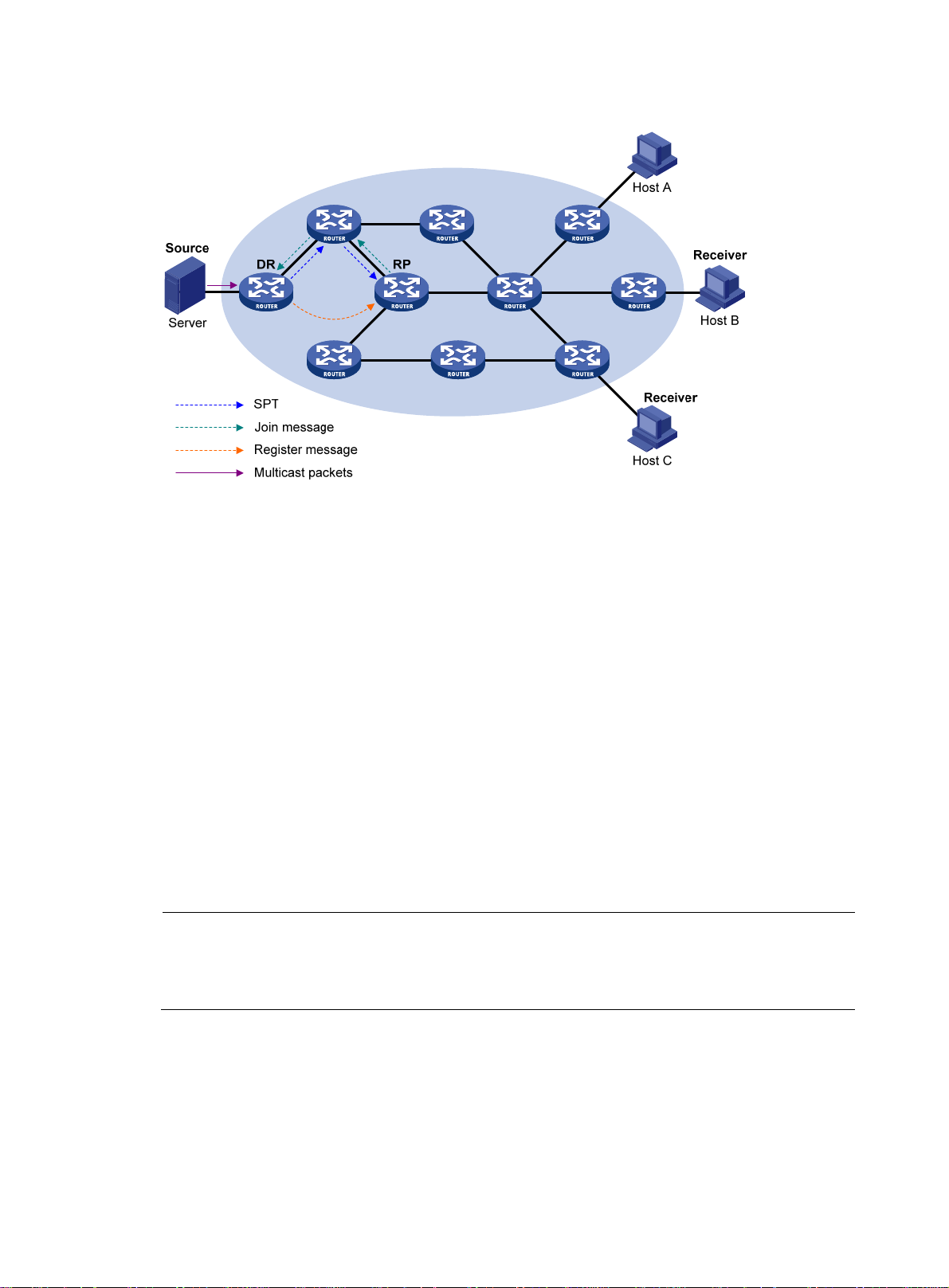
g
Figure 23 Multicast source registration
As shown in Figure 23, the multicast source registers with the RP as follows:
1. The multicast source S sends the first multicast packet to multicast group G.
2. After receiving the multicast packet, the DR that directly connects to the multicast source
encapsulates the packet in a PIM register message, and then sends the message to the
corresponding RP by unicast.
3. When the RP receives the register message, it does the following:
a. Extracts the multicast packet from the register message.
b. Forwards the multicast packet down the RPT.
c. Sends an (S, G) join message hop-by-hop toward the multicast source.
The routers along the path from the RP to the multicast source constitute an SPT branch. Each router
on this branch generates an (S, G) entry in its forwarding table. The source-side DR is the root of
the SPT, and the RP is the leaf of the SPT.
4. The subsequent multicast data from the multicast source travels along the established SPT to the RP.
Then, the RP forwards the data along the RPT to the receivers. When the multicast traffic arrives at
the RP along the SPT, the RP sends a register-stop message to the source-side DR by unicast to stop
the source registration process.
NOTE:
In this section, the RP is configured to initiate a switchover to SPT. If the RP is not confi
ured with switchover
to SPT, the DR at the multicast source side keeps encapsulating multicast data in register messages, and the
registration process will not stop unless no outgoing interfaces exist in the (S, G) entry on the RP.
Switchover to SPT
In a PIM-SM domain, a multicast group corresponds to one RP and RPT.
Before a switchover to SPT occurs, the source-side DR encapsulates all multicast data destined to the
multicast group in register messages and sends these messages to the RP. After receiving these register
messages, the RP extracts the multicast data and sends the multicast data down the RPT to the
48
Page 61

receiver-side DRs. The RP acts as a transfer station for all multicast packets. The whole process involves the
following issues:
• The source-side DR and the RP need to implement complicated encapsulation and de-encapsulation
of multicast packets.
• Multicast packets are delivered along a path that might not be the shortest one.
• An increase in multicast traffic adds a great burden on the RP, increasing the risk of failure.
To solve these issues, PIM-SM allows an RP or the receiver-side DR to initiate a switchover to SPT when the
traffic rate exceeds the threshold.
• The RP initiates a switchover to SPT:
The RP can periodically examine the passing-by multicast packets. If it finds that the traffic rate
exceeds a configurable threshold, the RP sends an (S, G) join message hop-by-hop toward the
multicast source to establish an SPT between the DR at the source side and the RP. Subsequent
multicast data travels along the established SPT to the RP.
For more information about the SPT switchover initiated by the RP, see "Multicast source
stration."
regi
• The receiver-side DR initiates a switchover to SPT:
After discovering that the traffic rate exceeds a configurable threshold, the receiver-side DR
initiates a switchover to SPT, as follows:
a. The receiver-side DR sends an (S, G) join message hop-by-hop toward the multicast source.
When the join message reaches the source-side DR, all the routers on the path have created the
(S, G) entry in their forwarding table, establishing an SPT branch.
b. When the multicast packets travel to the router where the RPT and the SPT deviate, the router
drops the multicast packets received from the RPT and sends an RP-bit prune message
hop-by-hop to the RP. After receiving this prune message, the RP sends a prune message
toward the multicast source (suppose only one receiver exists). Thus, SPT switchover is
completed.
c. Multicast data is directly sent from the source to the receivers along the SPT.
PIM-SM builds SPTs through SPT switchover more economically than PIM-DM does through the
flood-and-prune mechanism.
Assert
PIM-SM uses a similar assert mechanism as PIM-DM does. For more information, see "Assert."
BIDIR-PIM overview
In some many-to-many applications, such as multi-side video conference, there might be multiple
receivers interested in multiple multicast sources simultaneously. With PIM-DM or PIM-SM, each router
along the SPT must create an (S, G) entry for each multicast source, consuming a lot of system resources.
BIDIR-PIM addresses the problem. Derived from PIM-SM, BIDIR-PIM builds and maintains bidirectional
RPTs. Each RPT is rooted at an RP and connects multiple multicast sources with multiple receivers. Traffic
from the multicast sources is forwarded through the RPs to the receivers along the bidirectional RPTs. Each
router needs to maintain only one (*, G) multicast routing entry, saving system resources.
BIDIR-PIM is suitable for networks with dense multicast sources and dense receivers.
The operating mechanism of BIDIR-PIM is summarized as follows:
• Neighbor discovery
49
Page 62

• RP discovery
• DF election
• Bidirectional RPT building
Neighbor discovery
BIDIR-PIM uses the same neighbor discovery mechanism as PIM-SM does. For more information, see
"Neighbor discovery."
RP discovery
BIDIR-PIM uses the same RP discovery mechanism as PIM-SM does. For more information, see "RP
discovery."
In PIM-SM, an RP must be specified with a real IP address. In BIDIR-PIM, however, an RP can be specified
with a virtual IP address, which is called the rendezvous point address (RPA). The link corresponding to
the RPA's subnet is called the "rendezvous point link (RPL)." All interfaces connected to the RPL can act
as the RP, and they back up one another.
In BIDIR-PIM, an RPF interface is the interface pointing to an RP, and an RPF neighbor is the address of
the next hop to the RP.
DF election
On a network segment with multiple multicast routers, the same multicast packets might be forwarded to
the RP repeatedly. To address this issue, BIDIR-PIM uses a DF election mechanism to elect a unique DF for
each RP on every network segment within the BIDIR-PIM domain, and allows only the DF to forward
multicast data to the RP.
DF election is not necessary for an RPL.
Figure 24 DF election
Router DRouter E
RP
Router B Router C
Ethernet
DF election message
Multicast packets
Router A
Source
As shown in Figure 24, without the DF election mechanism, both Router B and Router C can receive
multicast packets from Router A. They might both forward the packets to downstream routers on the local
subnet. As a result, the RP (Router E) receives duplicate multicast packets. With the DF election
mechanism, once receiving the RP information, Router B and Router C initiate a DF election process for
the RP:
50
Page 63

1. Router B and Router C multicast DF election messages to all PIM routers (224.0.0.13). The election
messages carry the RP's address, and the priority and metric of the unicast route, MBGP route, or
multicast static route to the RP.
2. The router with a route of the highest priority becomes the DF.
3. In the case of a tie, the router with the route of the lowest metric wins the DF election.
4. In the case of a tie in the metric, the router with the highest IP address wins.
Bidirectional RPT building
A bidirectional RPT comprises a receiver-side RPT and a source-side RPT. The receiver-side RPT is rooted
at the RP and takes the routers directly connected to the receivers as leaves. The source-side RPT is also
rooted at the RP but takes the routers directly connected to the sources as leaves. The processes for
building these two parts are different.
Figure 25 RPT building at the receiver side
As shown in Figure 25, the process for building a receiver-side RPT is similar to that for building an RPT
in PIM-SM:
1. When a receiver joins multicast group G, it uses an IGMP message to inform the directly
connected router.
2. After getting the receiver information, the router sends a join message, which is forwarded
hop-by-hop to the RP of the multicast group.
3. The routers along the path from the receiver's directly connected router to the RP form an RPT
branch, and each router on this branch adds a (*, G) entry to its forwarding table. The * means
any multicast source.
When a receiver is no longer interested in the multicast data addressed to multicast group G, the directly
connected router sends a prune message, which goes hop-by-hop along the reverse direction of the RPT
to the RP. After receiving the prune message, each upstream node deletes the interface connected to the
downstream node from the outgoing interface list and examines whether it has receivers in that multicast
group. If not, the router continues to forward the prune message to its upstream router.
51
Page 64

Figure 26 RPT building at the multicast source side
As shown in Figure 26, the process for building a source-side RPT is relatively simple:
4. When a multicast source sends multicast packets to multicast group G, the DF in each network
segment unconditionally forwards the packets to the RP.
5. The routers along the path from the source's directly conn ected route r to th e RP f orm an RPT branch.
Each router on this branch adds a (*, G) entry to its forwarding table. The * means any multicast
source.
After a bidirectional RPT is built, multicast traffic is forwarded along the source-side RPT and receiver-side
RPT from sources to receivers.
If a receiver and a multicast source are at the same side of the RP, the source-side RPT and the
receiver-side RPT might meet at a node before reaching the RP. The multicast packets that the multicast
source sends to the receiver are directly forwarded by the node to the receiver, instead of by the RP.
Administrative scoping overview
Typically, a PIM-SM domain or BIDIR-PIM domain contains only one BSR. The BSR advertises RP-set
information within the entire PIM-SM domain or BIDIR-PIM domain. The information for all multicast
groups is forwarded within the network scope that the BSR administers. This is called the "non-scoped
BSR mechanism."
To implement refined management, you can divide a PIM-SM domain or BIDIR-PIM domain into one
global-scoped zone and multiple administratively scoped zones (admin-scoped zones). This is called the
"administrative scoping mechanism."
The administrative scoping mechanism effectively releases stress on the management in a single-BSR
domain and enables provision of zone-specific services through private group addresses.
Admin-scoped zones are divided to specific multicast groups. Zone border routers (ZBRs) form the
boundary of the admin-scoped zone. Each admin-scoped zone maintains one BSR, which serves
multicast groups within a specific range. Multicast protocol packets, such as assert messages and
bootstrap messages, for a specific group range cannot cross the admin-scoped zone boundary.
52
Page 65

Multicast group ranges within different admin-scoped zones can be overlapped. A multicast group is
valid only within its local admin-scoped zone, and functions as a private group address.
The global-scoped zone maintains a BSR, which serves the multicast groups that do not belong to any
admin-scoped zone.
Relationship between admin-scoped zones and the global-scoped zone
The global-scoped zone and each admin-scoped zone have their own C-RPs and BSRs. These devices are
effective only on their respective zones, and the BSR election and the RP election are implemented
independently. Each admin-scoped zone has its own boundary. The multicast information within a zone
cannot cross this boundary in either direction. You can have a better understanding of the global-scoped
zone and admin-scoped zones based on geographical locations and multicast group address ranges.
• In view of geographical locations:
An admin-scoped zone is a logical zone for particular multicast groups. The multicast packets for
such multicast groups are confined within the local admin-scoped zone and cannot cross the
boundary of the zone.
Figure 27 Relationship in view of geographical locations
As shown in Figure 27, for the multicast groups in a specific group address range, the
admin-scoped zones must be geographically separated and isolated. A router cannot belong to
multiple admin-scoped zones. In other words, different admin-scoped zones contain different
routers. However, the global-scoped zone includes all routers in the PIM-SM domain or BIDIR-PIM
domain. Multicast packets that do not belong to any admin-scoped zones are forwarded in the
entire PIM-SM domain or BIDIR-PIM domain.
• In view of multicast group address ranges:
Each admin-scoped zone serves specific multicast groups, of which the multicast group addresses
are valid only within the local zone. The multicast groups of different admin-scoped zones might
have intersections. All the multicast groups other than those of the admin-scoped zones are served
by the global-scoped zone.
53
Page 66

Figure 28 Relationship in view of multicast group address ranges
Admin-scope 1
G1 address
Global-scope
−G1−G2 address
G
As shown in Figure 28, the admin-scoped zones 1 and 2 have no intersection, but the
admin-scoped zone 3 is a subset of the admin-scoped zone 1. The global-scoped zone serves all
the multicast groups that are not covered by the admin-scoped zones 1 and 2, that is, G−G1−G2
in this case.
PIM-SSM overview
The SSM model and the ASM model are opposites. The ASM model includes the PIM-DM and PIM-SM
modes. The SSM model can be implemented by leveraging part of the PIM-SM technique. It is also called
"PIM-SSM."
The SSM model provides a solution for source-specific multicast. It maintains the relationship between
hosts and routers through IGMPv3.
Admin-scope 3
G3 address
Admin-scope 2
G2 address
In actual application, part of IGMPv3 or PIM-SM technique is adopted to implement the SSM model. In
the SSM model, receivers locate a multicast source by means of advertisements, consultancy, and so on.
No RP or RPT is required, no source registration process exists, and the MSDP is not needed for
discovering sources in other PIM domains.
The operating mechanism of PIM-SSM is summarized as follows:
• Neighbor discovery
• DR election
• SPT building
Neighbor discovery
PIM-SSM uses the same neighbor discovery mechanism as in PIM-DM and PIM-SM. See "Neighbor
discovery."
DR election
PIM-SSM uses the same DR election mechanism as in PIM-SM. See "DR election."
SPT building
The decision to build an RPT for PIM-SM or an SPT for PIM-SSM depends on whether the multicast group
that the receiver will join falls into the SSM group range (SSM group range reserved by IANA is
232.0.0.0/8).
54
Page 67

Figure 29 SPT building in PIM-SSM
Host A
Source
Server
SPT
Subscribe message
Multicast packets
RP
DR
DR
Receiver
Host C
Receiver
Host B
As shown in Figure 29, Host B and Host C are multicast information receivers. They send IGMPv3 report
messages to the respective DRs to express their interest in the information about the specific multicast
source S.
After receiving a report message, the DR first examines whether the group address in this message falls
into the SSM group range and does the following:
• If the group address falls into the SSM group range, the DR sends a subscribe message for channel
subscription hop-by-hop toward the multicast source S.
An (S, G) entry is created on all routers on the path from the DR to the source. An SPT is thereby
built in the network, with the source S as its root and receivers as its leaves. This SPT is the
transmission channel in PIM-SSM.
• If the group address does not fall into the SSM group range, the receiver-side DR sends a (*, G) join
message to the RP, and the source-side DR registers the multicast source.
In PIM-SSM, the term "channel" refers to a multicast group, and the term "channel subscription" refers to
a join message.
Relationship among PIM protocols
In a PIM network, PIM-DM cannot run together with PIM-SM, BIDIR-PIM, or PIM-SSM. However, PIM-SM,
BIDIR-PIM, and PIM-SSM can run together. When they run together, which one is chosen for a receiver
trying to join a group depends, as shown in Figure 30.
F
or more information about IGMP SSM mapping, see "Configuring IGMP."
55
Page 68
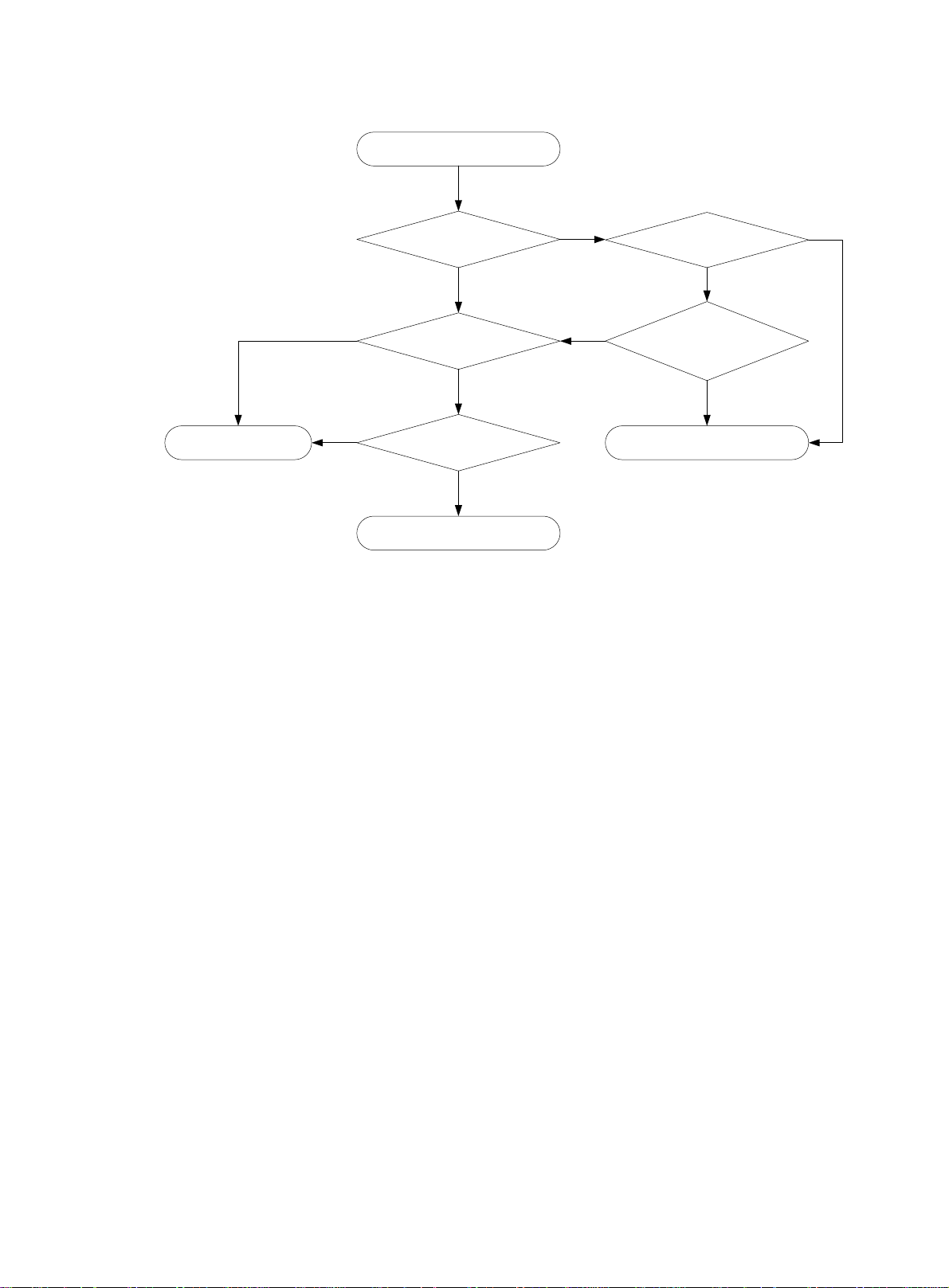
Figure 30 Relationship among PIM protocols
A receiver joins multicast group G.
No
PIM-SM runs for G.
No
PIM support for VPNs
To support PIM for VPNs, a multicast router that runs PIM maintains an independent set of PIM neighbor
table, multicast routing table, BSR information, and RP-set information for each VPN.
G is in the
SSM group range?
No
BIDIR-PIM is enabled?
Yes
G has a BIDIR-PIM RP?
Yes
BIDIR-PIM runs for G.
Yes
A multicast source is
specified?
No
An IGMP-SSM mapping is
configured for G?
PIM-SSM runs for G.
Yes
No
Yes
After receiving a multicast data packet, the multicast router checks which VPN the data packet belongs
to, and then forwards the packet according to the multicast routing table for that VPN or creates a
multicast routing entry for that VPN.
Protocols and standards
• RFC 3973, Protocol Independent Multicast-Dense Mode (PIM-DM): Protocol Specification(Revised)
• RFC 4601, Protocol Independent Multicast-Sparse Mode (PIM-SM): Protocol Specification (Revised)
• RFC 5015, Bidirectional Protocol Independent Multicast (BIDIR-PIM)
• RFC 5059, Bootstrap Router (BSR) Mechanism for Protocol Independent Multicast (PIM)
• RFC 4607, Source-Specific Multicast for IP
• Draft-ietf-ssm-overview-05, An Overview of Source-Specific Multicast (SSM)
Configuring PIM-DM
This section describes how to configure PIM-DM.
56
Page 69

A
PIM-DM configuration task list
Task Remarks
Enabling PIM-DM Required.
Enabling state-refresh capability Optional.
Configuring state-refresh parameters Optional.
Configuring PIM-DM graft retry period Optional.
Configuring common PIM features Optional.
Configuration prerequisites
Before you configure PIM-DM, complete the following tasks:
• Configure any unicast routing protocol so that all devices in the domain are interoperable at the
network layer.
• Determine the interval between state-refresh messages.
• Determine the minimum time to wait before receiving a new refresh message.
• Determine the TTL value of state-refresh messages.
• Determine the graft retry period.
Enabling PIM-DM
When PIM-DM is enabled, a router sends hello messages periodically to discover PIM neighbors and
processes messages from the PIM neighbors. When you deploy a PIM-DM domain, enable PIM-DM on
all non-border interfaces of the routers.
PIM-DM does not work with multicast groups in the SSM group range.
IMPORTANT:
ll the interfaces on a device must operate in the same PIM mode.
Enabling PIM-DM globally on the public network
Step Command Remarks
1. Enter system view.
2. Enable IP multicast routing.
3. Enter interface view.
4. Enable PIM-DM.
system-view N/A
multicast routing-enable Disabled by default.
interface interface-type
interface-number
pim dm Disabled by default.
Enabling PIM-DM in a VPN instance
Step Command Description
1. Enter system view.
system-view N/A
N/A
57
Page 70

Step Command Description
N/A
2. Create a VPN instance and
enter VPN instance view.
3. Configure an RD for the VPN
instance.
ip vpn-instance vpn-instance-name
route-distinguisher
route-distinguisher
For more information about this
command, see MPLS Command
Reference.
Not configured by default.
For more information about this
command, see MPLS Command
Reference.
4. Enable IP multicast routing.
5. Enter interface view.
6. Bind the interface with a VPN
instance.
7. Enable PIM-DM.
multicast routing-enable Disabled by default.
interface interface-type
interface-number
ip binding vpn-instance
vpn-instance-name
pim dm Disabled by default.
Enabling state-refresh capability
Pruned interfaces resume multicast forwarding when the pruned state times out. To prevent this, the router
with the multicast source attached periodically sends an (S, G) state-refresh message, which is forwarded
hop-by-hop along the initial multicast flooding path of the PIM-DM domain, to refresh the prune timer
state of all the routers on the path. A shared-media subnet can have the state-refresh capability only if the
state-refresh capability is enabled on all PIM routers on the subnet.
To enable the state-refresh capability:
N/A
By default, an interface belongs to
the public network, and is not
bound with any VPN instance.
For more information about this
command, see MPLS Command
Reference.
Step Command Remarks
1. Enter system view.
2. Enter interface view.
3. Enable the state-refresh
capability.
system-view N/A
interface interface-type
interface-number
pim state-refresh-capable
Configuring state-refresh parameters
The router directly connected with the multicast source periodically sends state-refresh messages. You can
configure the interval for sending such messages.
A router might receive multiple state-refresh messages within a short time. Some messages might be
duplicated messages. To keep a router from receiving such duplicated messages, you can configure the
time that the router must wait before it receives next state-refresh message. If the router receives a new
state-refresh message within the waiting time, it discards the message. If this timer times out, the router
will accept a new state-refresh message, refresh its own PIM-DM state, and reset the waiting timer.
58
N/A
Optional.
Enabled by default.
Page 71

The TTL value of a state-refresh message decrements by 1 whenever it passes a router before it is
forwarded to the downstream node until the TTL value comes down to 0. In a small network, a
state-refresh message might cycle in the network. To effectively control the propagation scope of
state-refresh messages, configure an appropriate TTL value based on the network size.
Perform the following configurations on all routers in the PIM domain.
To configure state-refresh parameters:
Step Command Remarks
1. Enter system view.
system-view N/A
2. Enter public network PIM view or
VPN instance PIM view.
3. Configure the interval between
state-refresh messages.
4. Configure the time to wait before
receiving a new state-refresh
message.
5. Configure the TTL value of
state-refresh messages.
pim [ vpn-instance
vpn-instance-name ]
state-refresh-interval interval
state-refresh-rate-limit interval
state-refresh-ttl ttl-value
Configuring PIM-DM graft retry period
In PIM-DM, graft messages are the only type of messages that involve the acknowledgment mechanism.
In a PIM-DM domain, a router sends a graft message to an upstream router. If the router does not receive
a graft-ack message from the upstream router within the specified time, the router send new graft
messages at a configurable interval (called a graft retry period). The router will keep sending graft
messages until it receives a graft-ack message from the upstream router.
For more information about the configuration of other timers in PIM-DM, see "Configuring common PIM
timer
s."
N/A
Optional.
60 seconds by default.
Optional.
30 seconds by default.
Optional.
255 by default.
To configure the graft retry period:
Step Command Remarks
1. Enter system view.
2. Enter interface view.
3. Configure the graft retry
period.
Configuring PIM-SM
This section describes how to configure PIM-SM.
system-view N/A
interface interface-type
interface-number
pim timer graft-retry interval
59
N/A
Optional.
3 seconds by default.
Page 72

PIM-SM configuration task list
Task Remarks
Enabling PIM-SM Required.
Configuring a static RP
Configuring an RP
Configuring a BSR
Configuring administrative scoping
Configuring multicast source registration Optional.
Configuring switchover to SPT Optional.
Configuring common PIM features Optional.
Configuring a C-RP
Enabling auto-RP
Configuring C-RP timers globally Optional.
Configuring a C-BSR Required.
Configuring a PIM domain border Optional.
Configuring global C-BSR parameters Optional.
Configuring C-BSR timers Optional.
Disabling BSM semantic fragmentation Optional.
Enabling administrative scoping Optional.
Configuring an admin-scoped zone boundary Optional.
Configuring C-BSRs for each admin-scoped zone
and the global-scoped zone
Required.
Use any
method.
Optional.
Configuration prerequisites
Before you configure PIM-SM, complete the following tasks:
• Configure any unicast routing protocol so that all devices in the domain are interoperable at the
network layer.
• Determine the IP address of a static RP and the ACL rule defining the range of multicast groups to
be served by the static RP.
• Determine the C-RP priority and the ACL rule defining the range of multicast groups to be served by
each C-RP.
• Determine the legal C-RP address range and the ACL rule defining the range of multicast groups to
be served.
• Determine the C-RP-Adv interval.
• Determine the C-RP timeout timer.
• Determine the C-BSR priority.
• Determine the hash mask length.
• Determine the ACL rule defining a legal BSR address range.
• Determine the BS period.
• Determine the BS timeout timer.
• Determine the ACL rule for register message filtering.
60
Page 73

A
• Determine the register suppression time.
• Determine the register probe time.
• Determine the multicast traffic rate threshold, ACL rule, and sequencing rule for a switchover to SPT.
• Determine the interval of checking the traffic rate threshold before a switchover to SPT.
Enabling PIM-SM
With PIM-SM enabled, a router sends hello messages periodically to discover PIM neighbors and
processes messages from the PIM neighbors. To deploy a PIM-SM domain, enable PIM-SM on all
non-border interfaces of the routers.
IMPORTANT:
ll the interfaces on a device must be enabled with the same PIM mode.
Enabling PIM-SM globally on the public network
Step Command Remarks
1. Enter system view.
system-view N/A
2. Enable IP multicast routing.
3. Enter interface view.
4. Enable PIM-SM.
Enabling PIM-SM in a VPN instance
Step Command Description
1. Enter system view.
2. Create a VPN instance and
enter VPN instance view.
3. Configure an RD for the VPN
instance.
4. Enable IP multicast routing.
5. Enter interface view.
multicast routing-enable Disabled by default.
interface interface-type
interface-number
pim sm Disabled by default.
system-view N/A
ip vpn-instance vpn-instance-name
route-distinguisher
route-distinguisher
multicast routing-enable Disabled by default.
interface interface-type
interface-number
N/A
N/A
For more information about this
command, see MPLS Command
Reference.
Not configured by default.
For more information about this
command, see MPLS Command
Reference.
N/A
By default, an interface belongs to
the public network, and is not
6. Bind the interface with a VPN
instance.
7. Enable PIM-SM.
ip binding vpn-instance
vpn-instance-name
pim sm Disabled by default.
61
bound with any VPN instance.
For more information about this
command, see MPLS Command
Reference.
Page 74

Configuring an RP
An RP can be manually configured or dynamically elected through the BSR mechanism. For a large PIM
network, static RP configuration is a tedious job. Generally, static RP configuration is just a backup
method for the dynamic RP election mechanism to enhance the robustness and operational
manageability of a multicast network.
When both PIM-SM and BIDIR-PIM run on the PIM network, do not use the same RP to serve PIM-SM and
BIDIR-PIM. Otherwise, exceptions might occur to the PIM routing table.
Configuring a static RP
If only one dynamic RP exists in a network, manually configuring a static RP can avoid communication
interruption because of single-point failures. It can also avoid frequent message exchange between C-RPs
and the BSR.
To make a static RP to work correctly, you must perform this configuration on all routers in the PIM-SM
domain and specify the same RP address.
To configure a static RP:
Step Command
1. Enter system view.
2. Enter public network PIM view
or VPN instance PIM view.
3. Configure a static RP for
PIM-SM.
Configuring a C-RP
In a PIM-SM domain, you can configure routers that intend to become the RP as C-RPs. The BSR collects
the C-RP information by receiving the C-RP-Adv messages from C-RPs or auto-RP announcements from
other routers and organizes the information into an RP-set, which is flooded throughout the entire network.
Then, the other routers in the network calculate the mappings between specific group ranges and the
corresponding RPs based on the RP-set. HP recommends that you configure C-RPs on backbone routers.
To guard against C-RP spoofing, you must configure a legal C-RP address range and the range of
multicast groups to be served on the BSR. In addition, because every C-BSR can become the BSR, you
must configure the same filtering policy on all C-BSRs in the PIM-SM domain.
When configuring a C-RP, ensure a relatively large bandwidth between this C-RP and the other devices
in the PIM-SM domain.
To configure a C-RP:
Remarks
system-view N/A
pim [ vpn-instance
vpn-instance-name ]
static-rp rp-address [ acl-number ]
[ preferred ]
N/A
By default, no static RP is
configured.
Step Command Remarks
1. Enter system view.
2. Enter public network PIM view
or VPN instance PIM view.
3. Configure an interface to be a
C-RP for PIM-SM.
system-view
pim [ vpn-instance vpn-instance-name ]
c-rp interface-type interface-number
[ group-policy acl-number | priority
priority | holdtime hold-interval |
advertisement-interval adv-interval ] *
62
N/A
N/A
No C-RPs are configured by
default.
Page 75

Step Command Remarks
4. Configure a legal C-RP
address range and the range
of multicast groups to be
served.
Enabling auto-RP
Auto-RP announcement and discovery messages are addressed to the multicast group addresses
224.0.1.39 and 224.0.1.40, respectively. With auto-RP enabled on a device, the device can receive
these two types of messages and record the RP information carried in such messages.
To enable auto-RP:
Step Command Remarks
1. Enter system view.
crp-policy acl-number
system-view N/A
Optional.
No restrictions by default.
2. Enter public network PIM view
or VPN instance PIM view.
3. Enable auto-RP.
Configuring C-RP timers globally
To enable the BSR to distribute the RP-set information within the PIM-SM domain, C-RPs must periodically
send C-RP-Adv messages to the BSR. The BSR learns the RP-set information from the received messages,
and encapsulates its own IP address together with the RP-set information in its bootstrap messages. The
BSR then floods the bootstrap messages to all PIM routers in the network.
Each C-RP encapsulates a timeout value in its C-RP-Adv messages. After receiving a C-RP-Adv message,
the BSR obtains this timeout value and starts a C-RP timeout timer. If the BSR fails to hear a subsequent
C-RP-Adv message from the C-RP when this timer times out, the BSR assumes the C-RP to have expired or
become unreachable.
For more information about the configuration of other timers in PIM-SM, see "Configuring common PIM
timer
s."
Configure the C-RP timers on C-RP routers.
To configure C-RP timers globally:
Step Command Remarks
1. Enter system view.
pim [ vpn-instance
vpn-instance-name ]
auto-rp enable Disabled by default.
system-view
N/A
N/A
2. Enter public network PIM view
or VPN instance PIM view.
3. Configure the C-RP-Adv
interval.
4. Configure C-RP timeout timer.
pim [ vpn-instance
vpn-instance-name ]
c-rp advertisement-interval interval
c-rp holdtime interval
63
N/A
Optional.
60 seconds by default.
Optional.
150 seconds by default.
Page 76

Configuring a BSR
A PIM-SM domain can have only one BSR, but must have at least one C-BSR. Any router can be
configured as a C-BSR. Elected from C-BSRs, the BSR is responsible for collecting and advertising RP
information in the PIM-SM domain.
Configuring a C-BSR
C-BSRs should b e con figured on route rs in the b ackb one network. When configuring a router as a C-BSR,
be sure to specify a PIM-SM-enabled interface on the router. The BSR election process is summarized as
follows:
• Initially, every C-BSR assumes itself to be the BSR of this PIM-SM domain and uses its interface IP
address as the BSR address to send bootstrap messages.
• When a C-BSR receives the bootstrap message of another C-BSR, it first compares its own priority
with the other C-BSR's priority carried in the message:
{ The C-BSR with a higher priority wins.
{ If a tie exists in the priority, the C-BSR with a higher IP address wins.
The loser uses the winner's BSR address to replace its own BSR address and no longer assumes
itself to be the BSR, and the winner retains its own BSR address and continues to assume itself to
be the BSR.
Configuring a legal range of BSR addresses enables filtering of bootstrap messages based on the
address range, therefore preventing a maliciously configured host from masquerading as a BSR. The
same configuration must be made on all routers in the PIM-SM domain. The following describes the
typical BSR spoofing cases and the corresponding preventive measures:
• Some maliciously configured hosts can forge bootstrap messages to fool routers and change RP
mappings. Such attacks often occur on border routers.
Because a BSR is inside the network whereas hosts are outside the network, you can protect a BSR
against attacks from external hosts by enabling the border routers to perform neighbor checks and
RPF checks on bootstrap messages and to discard unwanted messages.
• When an attacker c ontrols a route r in th e network o r when an i llegal router is present in the net work,
the attacker can configure this router as a C-BSR and make it win BSR election to control the right
of advertising RP information in the network. After a router is configured as a C-BSR, it automatically
floods the network with bootstrap messages.
Because a bootstrap message has a TTL value of 1, the whole network will not be affected as long
as the neighbor router discards these bootstrap messages. Therefore, with a legal BSR address
range configured on all routers in the entire network, all these routers will discard bootstrap
messages from out of the legal address range.
These preventive measures can partially protect the security of BSRs in a network. However, if an attacker
controls a legal BSR, the problem still exists.
Because the BSR and the other devices exchange a large amount of information in the PIM-SM domain,
provide a relatively large bandwidth between the C-BSRs and the other devices.
For C-BSRs interconnected through a GRE tunnel, configure static multicast routes to make sure the next
hop to a C-BSR is a tunnel interface. For more information about static multicast routes, see "Configuring
multicast routing and forwarding."
To configure a C-BSR:
64
Page 77

Step Command
1. Enter system view.
2. Enter public network PIM view
or VPN instance PIM view.
3. Configure an interface as a
C-BSR.
4. Configure a legal BSR
address range.
Configuring a PIM domain border
As the administrative core of a PIM-SM domain, the BSR sends the collected RP-set information in the form
of bootstrap messages to all routers in the PIM-SM domain.
A PIM domain border is a bootstrap message boundary. Each BSR has its specific service scope. A
number of PIM domain border interfaces partition a network into different PIM-SM domains. Bootstrap
messages cannot cross a domain border in either direction.
Perform the following configuration on routers that you want to configure as a PIM domain border.
To configure a PIM domain border:
Remarks
system-view N/A
pim [ vpn-instance
vpn-instance-name ]
c-bsr interface-type
interface-number [ hash-length
[ priority ] ]
bsr-policy acl-number
N/A
No C-BSRs are configured by
default.
Optional.
No restrictions on BSR address
range by default.
Step Command
1. Enter system view.
2. Enter interface view.
3. Configure a PIM domain
border.
Configuring global C-BSR parameters
In each PIM-SM domain, a unique BSR is elected from C-BSRs. The C-RPs in the PIM-SM domain send
advertisement messages to the BSR. The BSR summarizes the advertisement messages to form an RP-set
and advertises it to all routers in the PIM-SM domain. All the routers use the same hash algorithm to get
the RP address that corresponds to specific multicast groups.
The following rules apply to the hash mask length and C-BSR priority:
• You configure the hash mask length and C-BSR priority globally, in an admin-scoped zone, and in
the global-scoped zone.
• The values configured in the global-scoped zone or admin-scoped zone have preference over the
global values.
• If you do not configure these parameters in the global-scoped zone or admin-scoped zone, the
corresponding global values will be used.
Remarks
system-view N/A
interface interface-type
interface-number
pim bsr-boundary
N/A
By default, no PIM domain border
is configured.
For information about how to configure C-BSR parameters for an admin-scoped zone and global-scoped
zone, see "Configuring C-BSRs for each admin-scoped zone and the global-scoped zone."
P
erform the following configuration on C-BSR routers.
To configure C-BSR parameters:
65
Page 78

g
Step Command
1. Enter system view.
2. Enter public network PIM view
or VPN instance PIM view.
3. Configure the hash mask
length.
4. Configure the C-BSR priority.
Configuring C-BSR timers
The BSR election winner multicasts its own IP address and RP-set information through bootstrap messages
within the entire zone it serves. The BSR floods bootstrap messages throughout the network at the interval
of BS (BSR state) period. Any C-BSR that receives a bootstrap message retains the RP-set for the length of
BS timeout timer, during which no BSR election takes place. If no bootstrap message is received from the
BSR when the BS timeout timer expires, a new BSR election process is triggered among the C-BSRs.
Perform the following configuration on C-BSR routers.
To configure C-BSR timers:
Step Command
1. Enter system view.
Remarks
system-view N/A
pim [ vpn-instance
vpn-instance-name ]
c-bsr hash-length hash-length
c-bsr priority priority
N/A
Optional.
30 by default.
Optional.
By default, the C-BSR priority is 64.
Remarks
system-view N/A
2. Enter public network PIM view
or VPN instance PIM view.
3. Configure the BS period.
4. Configure the BS timeout
timer.
NOTE:
pim [ vpn-instance
vpn-instance-name ]
c-bsr interval interval
c-bsr holdtime interval
N/A
Optional.
By default, the BS period is
determined by the formula "BS
period = (BS timeout timer– 10) /
2." The default BS timeout timer is
130 seconds, so the default BS
period is (130 – 10) / 2 = 60
(seconds).
The BS period value must be
smaller than the BS timeout timer.
Optional.
By default, the BS timeout timer is
determined by the formula "BS
timeout timer = BS period × 2 +
10." The default BS period is 60
seconds, so the default BS timeout
timer = 60 × 2 + 10 = 130
(seconds).
If you confi
default one.
ure the BS period or the BS timeout timer, the system uses the configured one instead of the
66
Page 79

Disabling BSM semantic fragmentation
Generally, a BSR periodically distributes the RP-set information in bootstrap messages within the PIM-SM
domain. It encapsulates a BSM in an IP datagram and might split the datagram into fragments if the
message exceeds the MTU. In respect of such IP fragmentation, loss of a single IP fragment leads to
unavailability of the entire message.
Semantic fragmentation of BSMs can solve this issue. When a BSM exceeds the MTU, it is split to multiple
BSMFs.
• After receiving a BSMF that contains the RP-set information of one group range, a non-BSR router
updates corresponding RP-set information directly.
• If the RP-set information of one group range is carried in multiple BSMFs, a non-BSR router updates
corresponding RP-set information after receiving all these BSMFs.
Because the RP-set information contained in each segment is different, loss of some IP fragments will not
result in dropping of the entire message.
Generally, a BSR performs BSM semantic fragmentation according to the MTU of its BSR interface.
However, the semantic fragmentation of BSMs originated due to learning of a new PIM neighbor is
performed according to the MTU of the outgoing interface.
The function of BSM semantic fragmentation is enabled by default. A device that does not support this
function might regard a fragment as an entire message and learns only part of the RP-set information.
Therefore, if such devices exist in the PIM-SM domain, you need to disable the semantic fragmentation
function on the C-BSRs.
To disable the BSM semantic fragmentation function:
Step Command
1. Enter system view.
2. Enter public network PIM
view or VPN instance PIM
view.
3. Disable the BSM semantic
fragmentation function.
system-view N/A
pim [ vpn-instance
vpn-instance-name ]
undo bsm-fragment enable
Configuring administrative scoping
When administrative scoping is disabled, a PIM-SM domain has only one BSR. The BSR manages the
whole network. To manage your network more effectively and specifically, partition the PIM-SM domain
into multiple admin-scoped zones. Each admin-scoped zone maintains a BSR, which serves a specific
multicast group range. The global-scoped zone also maintains a BSR, which serves all the remaining
multicast groups.
Enabling administrative scoping
Before you configure an admin-scoped zone, you must enable administrative scoping.
Remarks
N/A
By default, the BSM semantic
fragmentation function is enabled.
Perform the following configuration on all routers in the PIM-SM domain.
To enable administrative scoping:
Step Command
1. Enter system view.
system-view N/A
67
Remarks
Page 80

Step Command
2. Enter public network PIM view
or VPN instance PIM view.
3. Enable administrative
scoping.
pim [ vpn-instance
vpn-instance-name ]
c-bsr admin-scope Disabled by default.
Configuring an admin-scoped zone boundary
ZBRs form the boundary of each admin-scoped zone. Each admin-scoped zone maintains a BSR, which
serves a specific multicast group range. Multicast protocol packets (such as assert messages and
bootstrap messages) that belong to this range cannot cross the admin-scoped zone boundary.
Perform the following configuration on routers that you want to configure as a ZBR.
To configure an admin-scoped zone boundary:
Step Command
1. Enter system view.
2. Enter interface view.
3. Configure a multicast
forwarding boundary.
system-view N/A
interface interface-type
interface-number
multicast boundary group-address
{ mask | mask-length }
Remarks
N/A
Remarks
N/A
By default, no multicast forwarding
boundary is configured.
The group-address { mask |
mask-length } argument can
specify the multicast groups that an
admin-scoped zone serves, in the
range of 239.0.0.0/8.
Configuring C-BSRs for each admin-scoped zone and the global-scoped zone
In a network with administrative scoping enabled, group-range-specific BSRs are elected from C-BSRs.
C-RPs in the network send advertisement messages to the specific BSR. The BSR summarizes the
advertisement messages to form an RP-set and advertises it to all routers in the specific admin-scoped
zone. All the routers use the same hash algorithm to get the RP address corresponding to the specific
multicast group.
The following rules apply to the hash mask length and C-BSR priority:
• You can configure these parameters globally, for an admin-scoped zone, and for the global-scoped
zone.
• The values of these parameters configured for the global-scoped zone or an admin-scoped zone
have preference over the global values.
• If you do not configure these parameters for the global-scoped zone or an admin-scoped zone, the
corresponding global values are used.
For configuration of global C-BSR parameters, see "Configuring global C-BSR parameters."
Configure C-BSRs for each admin-scoped zone and the global-scoped zone.
• Configure C-BSRs for each admin-scoped zone:
Perform the following configuration on the routers that you want to configure as C-BSRs in
admin-scoped zones.
To configure a C-BSR for an admin-scoped zone:
68
Page 81

Step Command
1. Enter system view.
2. Enter public network PIM view
or VPN instance PIM view.
3. Configure a C-BSR for an
admin-scoped zone.
system-view N/A
pim [ vpn-instance
vpn-instance-name ]
c-bsr group group-address { mask |
mask-length } [ hash-length
hash-length | priority priority ] *
Remarks
N/A
No C-BSRs are configured for an
admin-scoped zone by default.
The group-address { mask |
mask-length } argument can
specify the multicast groups that
the C-BSR serves, in the range of
239.0.0.0/8.
• Configure C-BSRs for the global-scoped zone:
Perform the following configuration on the routers that you want to configure as C-BSRs in the
global-scoped zone.
To configure a C-BSR for the global-scoped zone:
Step Command
1. Enter system view.
2. Enter public network PIM view
or VPN instance PIM view.
system-view N/A
pim [ vpn-instance
vpn-instance-name ]
Remarks
N/A
3. Configure a C-BSR for the
global-scoped zone.
c-bsr global [ hash-length
hash-length | priority priority ] *
Configuring multicast source registration
Within a PIM-SM domain, the source-side DR sends register messages to the RP, and these register
messages have different multicast source or group addresses. You can configure a filtering rule to filter
register messages so that the RP can serve specific multicast groups. If the filtering rule denies an (S, G)
entry, or if the filtering rule does not define the action for this entry, the RP will send a register-stop
message to the DR to stop the registration process for the multicast data.
In view of information integrity of register messages in the transmission process, you can configure the
device to calculate the checksum based on the entire register messages. However, to reduce the
workload of encapsulating data in register messages and for the sake of interoperability, do not use this
checksum calculation method.
When receivers stop receiving multicast data addressed to a certain multicast group through the RP (that
is, the RP stops serving the receivers of that multicast group), or when the RP starts receiving multicast
data from the multicast source along the SPT, the RP sends a register-stop message to the source-side DR.
After receiving this message, the DR stops sending register messages encapsulated with multicast data
and starts a register-stop timer. Before the register-stop timer expires, the DR sends a null register message
(a register message without encapsulated multicast data) to the RP. If the DR receives a register-stop
message during the register probe time, it will reset its register-stop timer. Otherwise, the DR starts
sending register messages with encapsulated data again when the register-stop timer expires.
No C-BSRs are configured for the
global-scoped zone by default.
The register-stop timer is set to a random value chosen uniformly from the interval (0.5 times
register_suppression_time, 1.5 times register_suppression_time) minus register_probe_time.
69
Page 82

Configure a filtering rule for register messages on all C-RP routers and configure them to calculate the
checksum based on the entire register messages. Configure the register suppression time and the register
probe time on all routers that might become source-side DRs.
To configure register-related parameters:
Step Command Remarks
1. Enter system view.
system-view N/A
2. Enter public network PIM view
or VPN instance PIM view.
3. Configure a filtering rule for
register messages.
4. Configure the device to
calculate the checksum based
on the entire register
messages.
5. Configure the register
suppression time.
6. Configure the register probe
time.
pim [ vpn-instance
vpn-instance-name ]
register-policy acl-number
register-whole-checksum
register-suppression-timeout
interval
probe-interval interval
Configuring switchover to SPT
Both the receiver-side DR and the RP can periodically check the traffic rate of passing-by multicast packets
and thus trigger a switchover to SPT.
Perform the following configuration on routers that might become receiver-side DRs and on C-RP routers.
To configure SPT switchover:
N/A
Optional.
No register filtering rule by default.
Optional.
By default, the checksum is
calculated based on the header of
register messages.
Optional.
60 seconds by default.
Optional.
5 seconds by default.
Step Command Remarks
1. Enter system view.
2. Enter public network PIM view
or VPN instance PIM view.
3. Configure the criteria for
triggering a switchover to SPT.
4. Configure the interval of
checking the traffic rate
threshold before initiating a
switchover to SPT.
system-view N/A
pim [ vpn-instance
vpn-instance-name ]
spt-switch-threshold { traffic-rate
| infinity } [ group-policy
acl-number [ order order-value] ]
timer spt-switch interval
70
N/A
Optional.
By default, the device switches to the
SPT immediately after it receives the
first multicast packet.
If the multicast source is learned
through MSDP, the device will switch
to the SPT immediately after it
receives the first multicast packet, no
matter how big the traffic rate
threshold is set.
Optional.
15 seconds by default.
Page 83

Configuring BIDIR-PIM
This section describes how to configure BIDIR-PIM.
BIDIR-PIM configuration task list
Task Remarks
Enabling PIM-SM Required.
Enabling BIDIR-PIM Required.
Configuring a static RP
Configuring a C-RP
Configuring an RP
Enabling auto-RP
Configuring C-RP timers globally Optional.
Configuring a C-BSR Required.
Configuring a BIDIR-PIM domain border Optional.
Required.
Use any method.
Configuring a BSR
Configuring administrative scoping
Configuring common PIM features Optional.
Configuration prerequisites
Before you configure BIDIR-PIM, complete the following tasks:
• Configure a unicast routing protocol so that all devices in the domain can reach each other.
• Determine the IP address of a static RP and the ACL that defines the range of the multicast groups
to be served by the static RP.
• Determine the C-RP priority and the ACL that defines the range of multicast groups to be served by
each C-RP.
• Determine the legal C-RP address range and the ACL that defines the range of multicast groups to
be served.
Configuring global C-BSR parameters Optional.
Configuring C-BSR timers Optional.
Disabling BSM semantic fragmentation Optional.
Enabling administrative scoping Optional.
Configuring an admin-scoped zone boundary Optional.
Configuring C-BSRs for each admin-scoped
zone and the global-scoped zone
Optional.
• Determine the C-RP-Adv interval.
• Determine the C-RP timeout timer.
• Determine the C-BSR priority.
• Determine the hash mask length.
• Determine the ACL defining the legal BSR address range.
• Determine the BS period.
• Determine the BS timeout timer.
71
Page 84

A
Enabling PIM-SM
Because BIDIR-PIM is implemented on the basis of PIM-SM, you must enable PIM-SM before enabling
BIDIR-PIM. To deploy a BIDIR-PIM domain, enable PIM-SM on all non-border interfaces of the domain.
IMPORTANT:
ll interfaces on a device must be enabled with the same PIM mode.
Enabling PIM-SM globally for the public network
Step Command
1. Enter system view.
2. Enable IP multicast routing.
3. Enter interface view.
4. Enable PIM-SM.
Enabling PIM-SM for a VPN instance
Step Command
1. Enter system view.
2. Create a VPN instance and
enter VPN instance view.
3. Configure an RD for the VPN
instance.
4. Enable IP multicast routing.
Remarks
system-view N/A
multicast routing-enable Disabled by default.
interface interface-type
interface-number
pim sm Disabled by default.
N/A
Remarks
system-view
ip vpn-instance vpn-instance-name
route-distinguisher
route-distinguisher
multicast routing-enable Disabled by default.
N/A
N/A
For more information about this
command, see MPLS Command
Reference.
Not configured by default.
For more information about this
command, see MPLS Command
Reference.
5. Enter interface view.
6. Bind the interface with the
VPN instance.
7. Enable PIM-SM.
interface interface-type
interface-number
ip binding vpn-instance
vpn-instance-name
pim sm Disabled by default.
N/A
By default, an interface belongs to
the public network, and is not
bound with any VPN instance.
For more information about this
command, see MPLS Command
Reference.
Enabling BIDIR-PIM
Perform this configuration on all routers in the BIDIR-PIM domain.
To enable BIDIR-PIM:
72
Page 85

Step Command
1. Enter system view.
2. Enter public network PIM view
or VPN instance PIM view.
3. Enable BIDIR-PIM.
Configuring an RP
An RP can be manually configured or dynamically elected through the BSR mechanism. For a large PIM
network, static RP configuration is a tedious job. Generally, static RP configuration is just used as a
backup method for the dynamic RP election mechanism to enhance the robustness and operation
manageability of a multicast network.
When both PIM-SM and BIDIR-PIM run on the PIM network, do not use the same RP to serve PIM-SM and
BIDIR-PIM. Otherwise, exceptions might occur to the PIM routing table.
Configuring a static RP
If only one dynamic RP exists in a network, manually configuring a static RP can avoid communication
interruption due to single-point failures and avoid frequent message exchange between C-RPs and the
BSR.
In BIDIR-PIM, a static RP can be specified with a virtual IP address. For example, if the IP addresses of the
interfaces at the two ends of a link are 10.1.1.1/24 and 10.1.1.2/24, you can specify a virtual IP address,
like 10.1.1.100/24, for the static RP. As a result, the link becomes an RPL.
Remarks
system-view N/A
pim [ vpn-instance
vpn-instance-name ]
bidir-pim enable Disabled by default.
N/A
To make a static RP to work correctly, you must perform this configuration on all routers in the BIDIR-PIM
domain and specify the same RP address.
To configure a static RP:
Step Command
1. Enter system view.
2. Enter public network PIM view
or VPN instance PIM view.
3. Configure a static RP for
BIDIR-PIM.
Configuring a C-RP
In a BIDIR-PIM domain, you can configure routers that intend to become the RP as C-RPs. The BSR collects
the C-RP information by receiving the C-RP-Adv messages from C-RPs or auto-RP announcements from
other routers. It organizes the information into an RP-set, which is flooded throughout the entire network.
Then, the other routers in the network calculate the mappings between specific group ranges and the
corresponding RPs based on the RP-set. HP recommends that you configure C-RPs on backbone routers.
To guard against C-RP spoofing, configure a legal C-RP address range and the range of multicast groups
to be served on the BSR. In addition, because every C-BSR has a chance to become the BSR, you must
configure the same filtering policy on all C-BSRs in the BIDIR-PIM domain.
Remarks
system-view N/A
pim [ vpn-instance
vpn-instance-name ]
static-rp rp-address [ acl-number ]
[ preferred ] bidir
N/A
No static RP by default.
When configuring a C-RP, ensure a relatively large bandwidth between this C-RP and the other devices
in the BIDIR-PIM domain.
73
Page 86

To configure a C-RP:
Step Command
1. Enter system view.
2. Enter public network PIM view
or VPN instance PIM view.
3. Configure an interface to be a
C-RP for BIDIR-PIM.
Enabling auto-RP
Auto-RP announcement and discovery messages are addressed to the multicast group addresses
224.0.1.39 and 224.0.1.40, respectively. With auto-RP enabled on a device, the device can receive
these two types of messages and record the RP information carried in such messages.
To enable auto-RP:
Step Command
1. Enter system view.
2. Enter public network PIM view
or VPN instance PIM view.
Remarks
system-view N/A
pim [ vpn-instance vpn-instance-name ] N/A
c-rp interface-type interface-number
[ group-policy acl-number | priority
priority | holdtime hold-interval |
advertisement-interval adv-interval ] *
bidir
No C-RP is configured by
default.
Remarks
system-view N/A
pim [ vpn-instance
vpn-instance-name ]
N/A
3. Enable auto-RP.
Configuring C-RP timers globally
To enable the BSR to distribute the RP-set information within the BIDIR-PIM domain, C-RPs must
periodically send C-RP-Adv messages to the BSR. The BSR learns the RP-set information from the received
messages, and encapsulates its own IP address together with the RP-set information in its bootstrap
messages. The BSR then floods the bootstrap messages to all PIM routers in the network.
Each C-RP encapsulates a timeout value in its C-RP-Adv messages. After receiving a C-RP-Adv message,
the BSR obtains this timeout value and starts a C-RP timeout timer. If the BSR fails to hear a subsequent
C-RP-Adv message from the C-RP within the timeout interval, the BSR assumes the C-RP to have expired
or become unreachable.
For more information about the configuration of other timers in BIDIR-PIM, see "Configuring common PIM
timer
s."
The C-RP timers need to be configured on C-RP routers.
To configure C-RP timers globally:
Step Command
1. Enter system view.
2. Enter public network PIM view
or VPN instance PIM view.
auto-rp enable Disabled by default.
Remarks
system-view N/A
pim [ vpn-instance
vpn-instance-name ]
N/A
3. Configure the C-RP-Adv
interval.
c-rp advertisement-interval interval
74
Optional.
60 seconds by default.
Page 87

Step Command
4. Configure C-RP timeout timer.
Configuring a BSR
A BIDIR-PIM domain can have only one BSR, but must have at least one C-BSR. Any router can be
configured as a C-BSR. Elected from C-BSRs, the BSR collects and advertises RP information in the
BIDIR-PIM domain.
Configuring a C-BSR
C-BSRs must be configured on routers in the backbone network. When configuring a router as a C-BSR,
be sure to specify a PIM-SM-enabled interface on the router. The BSR election process is as follows:
• Initially, every C-BSR assumes itself to be the BSR of the BIDIR-PIM domain, and uses its interface IP
address as the BSR address to send bootstrap messages.
• When a C-BSR receives the bootstrap message of another C-BSR, it first compares its own priority
with the other C-BSR's priority carried in message. The C-BSR with a higher priority wins. If a tie
exists in the priority, the C-BSR with a higher IP address wins. The loser uses the winner's BSR
address to replace its own BSR address and no longer assumes itself to be the BSR, and the winner
retains its own BSR address and continues assuming itself to be the BSR.
c-rp holdtime interval
Remarks
Optional.
150 seconds by default.
Configuring a legal range of BSR addresses enables filtering of bootstrap messages based on the
address range, thereby preventing a maliciously configured host from masquerading as a BSR. The same
configuration must be made on all routers in the BIDIR-PIM domain. The following are typical BSR
spoofing cases and the corresponding preventive measures:
• Some maliciously configured hosts can forge bootstrap messages to fool routers and change RP
mappings. Such attacks often occur on border routers. Because a BSR is inside the network whereas
hosts are outside the network, you can protect a BSR against attacks from external hosts by enabling
the border routers to perform neighbor checks and RPF checks on bootstrap messages and discard
unwanted messages.
• When a router in the network is controlled by an attacker or when an illegal router is present in the
network, the attacker can configure this router as a C-BSR and make it win BSR election to control
the right of advertising RP information in the network. After being configured as a C-BSR, a router
automatically floods the network with bootstrap messages. Because a bootstrap message has a TTL
value of 1, the whole network will not be affected as long as the neighbor router discards these
bootstrap messages. Therefore, with a legal BSR address range configured on all routers in the
entire network, all these routers will discard bootstrap messages from out of the legal address
range.
The preventive measures can partially protect the security of BSRs in a network. If a legal BSR is controlled
by an attacker, the preceding problem will still occur.
Because the BSR and the other devices exchange a large amount of information in the BIDIR-PIM domain,
provide a relatively large bandwidth between the C-BSRs and the other devices.
For C-BSRs interconnected through a GRE tunnel, configure static multicast routes to make sure the next
hop to a C-BSR is a tunnel interface. For more information about static multicast routes, see "Configuring
multicast routing and forwarding."
To configure a C-BSR:
75
Page 88

Step Command
1. Enter system view.
2. Enter public network PIM view
or VPN instance PIM view.
3. Configure an interface as a
C-BSR.
4. Configure a legal BSR
address range.
Configuring a BIDIR-PIM domain border
As the administrative core of a BIDIR-PIM domain, the BSR sends the collected RP-Set information in the
form of bootstrap messages to all routers in the BIDIR-PIM domain.
A BIDIR-PIM domain border is a bootstrap message boundary. Each BSR has its specific service scope.
A number of BIDIR-PIM domain border interfaces partition a network into different BIDIR-PIM domains.
Bootstrap messages cannot cross a domain border in either direction.
Perform the following configuration on routers that you want to configure as the PIM domain border.
To configure a BIDIR-PIM domain border:
Remarks
system-view N/A
pim [ vpn-instance
vpn-instance-name ]
c-bsr interface-type
interface-number [ hash-length
[ priority ] ]
bsr-policy acl-number
N/A
No C-BSRs are configured by
default.
Optional.
No restrictions on BSR address
range by default.
Step Command
1. Enter system view.
2. Enter interface view.
3. Configure a BIDIR-PIM
domain border.
Configuring global C-BSR parameters
In each BIDIR-PIM domain, a unique BSR is elected from C-BSRs. The C-RPs in the BIDIR-PIM domain send
advertisement messages to the BSR. The BSR summarizes the advertisement messages to form an RP-set
and advertises it to all routers in the BIDIR-PIM domain. All the routers use the same hash algorithm to get
the RP address corresponding to specific multicast groups.
The following rules apply to the hash mask length and C-BSR priority:
• You configure the hash mask length and C-BSR priority globally, in an admin-scoped zone, and in
the global-scoped zone.
• The values configured in the global-scoped zone or admin-scoped zone have preference over the
global values.
• If you do not configure these parameters in the global-scoped zone or admin-scoped zone, the
corresponding global values will be used.
Remarks
system-view N/A
interface interface-type
interface-number
pim bsr-boundary
N/A
By default, no BIDIR-PIM domain
border is configured.
For configuration of C-BSR parameters for an admin-scoped zone and global-scoped zone, see
"Configuring C-BSRs for each admin-scoped zone and the global-scoped zone."
Perform the following configuration on C-BSR routers.
To configure global C-BSR parameters:
76
Page 89

g
Step Command
1. Enter system view.
2. Enter public network PIM view
or VPN instance PIM view.
3. Configure the hash mask
length.
4. Configure the C-BSR priority.
Configuring C-BSR timers
The BSR election winner multicasts its own IP address and RP-Set information through bootstrap messages
within the entire zone it serves. The BSR floods bootstrap messages throughout the network at the interval
of the BS period.
Any C-BSR that receives a bootstrap message retains the RP-set for the length of BS timeout timer, during
which no BSR election takes place. If no bootstrap message is received from the BSR when the BS timeout
timer expires, a new BSR election process is triggered among the C-BSRs.
Perform the following configuration on C-BSR routers.
To configure C-BSR timers:
Remarks
system-view N/A
pim [ vpn-instance
vpn-instance-name ]
c-bsr hash-length hash-length
c-bsr priority priority
N/A
Optional.
30 by default.
Optional.
64 by default.
Step Command
1. Enter system view.
2. Enter public network PIM view
or VPN instance PIM view.
3. Configure the BS period.
4. Configure the BS timeout
timer.
system-view N/A
pim [ vpn-instance
vpn-instance-name ]
c-bsr interval interval
c-bsr holdtime interval
Remarks
N/A
Optional.
By default, the BS period is
determined by the formula "BS
period = (BS timeout timer – 10) /
2." The default BS timeout timer is
130 seconds, so the default BS
period is (130 – 10) / 2 = 60
(seconds).
The BS period value must be
smaller than the BS timeout timer.
Optional.
By default, the BS timeout timer is
determined by the formula "BS
timeout timer = BS period × 2 +
10." The default BS period is 60
seconds, so the default BS timeout
timer is 60 × 2 + 10 = 130
(seconds).
NOTE:
If you confi
ure the BS period or the BS timeout timer, the system uses the configured one instead of the
default one.
77
Page 90

Disabling BSM semantic fragmentation
Generally, a BSR periodically distributes the RP-set information in bootstrap messages within the
BIDIR-PIM domain. It encapsulates a BSM in an IP datagram and might split the datagram into fragments
if the message exceeds the MTU. In respect of such IP fragmentation, loss of a single IP fragment leads
to unavailability of the entire message.
Semantic fra gmentat ion of BSMs can solve t his issue. When a BSM exceeds the MT U, i t is split to BS MFs.
• After receiving a BSMF that contains the RP-set information of one group range, a non-BSR router
updates corresponding RP-set information directly.
• If the RP-set information of one group range is carried in multiple BSMFs, a non-BSR router updates
corresponding RP-set information after receiving all these BSMFs.
Because the RP-set information contained in each segment is different, loss of some IP fragments will not
result in dropping of the entire message.
Generally, a BSR performs BSM semantic fragmentation according to the MTU of its BSR interface.
However, the semantic fragmentation of BSMs originated due to learning of a new PIM neighbor is
performed according to the MTU of the outgoing interface.
The function of BSM semantic fragmentation is enabled by default. Devices not supporting this function
might deem a fragment as an entire message, thus learning only part of the RP-set information. Therefore,
if such devices exist in the BIDIR-PIM domain, you need to disable the semantic fragmentation function on
the C-BSRs.
To disable the BSM semantic fragmentation function:
Step Command
1. Enter system view.
2. Enter public network PIM
view or VPN instance PIM
view.
3. Disable the BSM semantic
fragmentation function.
system-view N/A
pim [ vpn-instance
vpn-instance-name ]
undo bsm-fragment enable
Configuring administrative scoping
When administrative scoping is disabled, a BIDIR-PIM domain has only one BSR. The BSR manages the
whole network. To manage your network more effectively and specifically, you can divide the BIDIR-PIM
domain into multiple admin-scoped zones. Each admin-scoped zone maintains a BSR, which serves a
specific multicast group range. The global-scoped zone also maintains a BSR, which serves all the rest
multicast groups.
Enabling administrative scoping
Before you configure an admin-scoped zone, you must enable administrative scoping first.
Remarks
N/A
By default, the BSM semantic
fragmentation function is enabled.
Perform the following configuration on all routers in the BIDIR-PIM domain.
To enable administrative scoping:
Step Command
1. Enter system view.
system-view N/A
78
Remarks
Page 91

Step Command
2. Enter public network PIM view
or VPN instance PIM view.
3. Enable administrative
scoping.
pim [ vpn-instance
vpn-instance-name ]
c-bsr admin-scope Disabled by default.
Configuring an admin-scoped zone boundary
The boundary of each admin-scoped zone is formed by ZBRs. Each admin-scoped zone maintains a BSR,
which serves a specific multicast group range. Multicast protocol packets (such as assert messages and
bootstrap messages) that belong to this range cannot cross the admin-scoped zone boundary.
Perform the following configuration on routers that you want to configure as a ZBR.
To configure an admin-scoped zone boundary:
Step Command
1. Enter system view.
2. Enter interface view.
3. Configure a multicast
forwarding boundary.
system-view N/A
interface interface-type
interface-number
multicast boundary group-address
{ mask | mask-length }
Remarks
N/A
Remarks
N/A
By default, no multicast forwarding
boundary is configured.
The group-address { mask |
mask-length } argument can
specify the multicast groups that an
admin-scoped zone serves, in the
range of 239.0.0.0/8.
Configuring C-BSRs for each admin-scoped zone and the global-scoped zone
In a network with administrative scoping enabled, group-range-specific BSRs are elected from C-BSRs.
C-RPs in the network send advertisement messages to the specific BSR. The BSR summarizes the
advertisement messages to form an RP-set and advertises it to all routers in the specific admin-scoped
zone. All the routers use the same hash algorithm to get the RP address corresponding to the specific
multicast group.
The following rules apply to the hash mask length and C-BSR priority:
• You can configure the hash mask length and C-BSR priority globally, for a admin-scoped zone, and
for the global-scoped zone.
• The values of these parameters configured for the global-scoped zone or an admin-scoped zone
have preference over the global values.
• If you do not configure these parameters for the global-scoped zone or an admin-scoped zone, the
corresponding global values are used.
For configuration of global C-BSR parameters, see "Configuring global C-BSR parameters."
Configure C-BSRs for each admin-scoped zone and the global-scoped zone.
• Configure C-BSRs for each admin-scoped zone:
Perform the following configuration on the routers that you want to configure as C-BSRs in
admin-scoped zones.
To configure a C-BSR for an admin-scoped zone:
79
Page 92

Step Command
1. Enter system view.
2. Enter public network PIM view
or VPN instance PIM view.
3. Configure a C-BSR for an
admin-scoped zone.
system-view N/A
pim [ vpn-instance
vpn-instance-name ]
c-bsr group group-address { mask |
mask-length } [ hash-length
hash-length | priority priority ] *
Remarks
N/A
No C-BSRs are configured for an
admin-scoped zone by default.
The group-address { mask |
mask-length } argument can
specify the multicast groups that
the C-BSR serves, in the range of
239.0.0.0/8.
• Configure C-BSRs for the global-scoped zone:
Perform the following configuration on the routers that you want to configure as C-BSRs in the
global-scoped zone.
To configure a C-BSR for the global-scoped zone:
Step Command
1. Enter system view.
2. Enter public network PIM view
or VPN instance PIM view.
system-view N/A
pim [ vpn-instance
vpn-instance-name ]
Remarks
N/A
3. Configure a C-BSR for the
global-scoped zone.
c-bsr global [ hash-length
hash-length | priority priority ] *
Configuring PIM-SSM
PIM-SSM needs the support of IGMPv3. Be sure to enable IGMPv3 on PIM routers with multicast
receivers.
PIM-SSM configuration task list
Complete these tasks to configure PIM-SSM:
Task Remarks
Enabling PIM-SM Required.
Configuring the SSM group range Optional.
Configuring common PIM features Optional.
Configuration prerequisites
No C-BSRs are configured for the
global-scoped zone by default.
Before you configure PIM-SSM, complete the following tasks:
• Configure any unicast routing protocol so that all devices in the domain are interoperable at the
network layer.
• Determine the SSM group range.
80
Page 93

A
Enabling PIM-SM
The implementation of the SSM model is based on some subsets of PIM-SM. Therefore, you must enable
PIM-SM before configuring PIM-SSM.
When you deploy a PIM-SSM domain, enable PIM-SM on non-border interfaces of the routers.
IMPORTANT:
ll the interfaces on a device must be enabled with the same PIM mode.
Enabling PIM-SM globally on the public network
Step Command Remarks
1. Enter system view.
system-view N/A
2. Enable IP multicast routing.
3. Enter interface view.
4. Enable PIM-SM.
Enabling PIM-SM in a VPN instance
Step Command Description
1. Enter system view.
2. Create a VPN instance and
enter VPN instance view.
3. Configure an RD for the VPN
instance.
4. Enable IP multicast routing.
5. Enter interface view.
multicast routing-enable Disabled by default.
interface interface-type
interface-number
pim sm Disabled by default.
system-view N/A
ip vpn-instance vpn-instance-name
route-distinguisher
route-distinguisher
multicast routing-enable Disabled by default.
interface interface-type
interface-number
N/A
N/A
For more information about this
command, see MPLS Command
Reference.
No RD is configured by default.
For more information about this
command, see MPLS Command
Reference.
N/A
By default, an interface belongs to
the public network, and it is not
6. Bind the interface with a VPN
instance.
7. Enable PIM-SM.
ip binding vpn-instance
vpn-instance-name
pim sm Disabled by default.
bound with any VPN instance.
For more information about this
command, see MPLS Command
Reference.
Configuring the SSM group range
Whether the PIM-SSM model or the PIM-SM model delivers the information from a multicast source the
receivers depends on whether the group address in the (S, G) packets that the receivers request falls into
81
Page 94

the SSM group range. All PIM-SM-enabled interfaces assume the PIM-SSM model for multicast groups
within this address range.
Configuration guidelines
• Perform the following configuration on all routers in the PIM-SSM domain.
• Make sure the same SSM group range is configured on all routers in the entire domain. Otherwise,
multicast information cannot be delivered through the SSM model.
• When a member of a multicast group in the SSM group range sends an IGMPv1 or IGMPv2 report
message, the device does not trigger a (*, G) join.
Configuration procedure
To configure an SSM multicast group range:
Step Command Remarks
1. Enter system view.
system-view N/A
2. Enter public network PIM view
or VPN instance PIM view.
3. Configure the SSM group
range.
pim [ vpn-instance
vpn-instance-name ]
ssm-policy acl-number
Configuring common PIM features
For the configuration tasks in this section, the following rules apply:
• The configurations made in PIM view are effective on all interfaces. The configurations made in
interface view are effective only on the current interface.
• A configuration made in interface view always has priority over the same configuration made in
PIM, regardless of the configuration sequence.
Configuration task list
Task Remarks
Configuring a multicast data filter Optional.
Configuring a hello message filter Optional.
Configuring PIM hello options Optional.
N/A
Optional.
232.0.0.0/8 by default.
Setting the prune delay timer Optional.
Configuring common PIM timers Optional.
Configuring join/prune message sizes Optional.
Configuration prerequisites
Before you configure common PIM features, complete the following tasks:
• Configure any unicast routing protocol so that all devices in the domain are interoperable at the
network layer.
• Configure PIM-DM, or PIM-SM, or PIM-SSM.
82
Page 95

• Determine the ACL rule for filtering multicast data.
• Determine the ACL rule defining a legal source address range for hello messages.
• Determine the priority for DR election (global value/interface level value).
• Determine the PIM neighbor timeout timer (global value/interface value).
• Determine the prune message delay (global value/interface level value).
• Determine the prune override interval (global value/interface level value).
• Determine the prune delay.
• Determine the hello interval (global value/interface level value).
• Determine the maximum delay between hello message (interface level value).
• Determine the assert timeout timer (global value/interface value).
• Determine the join/prune interval (global value/interface level value).
• Determine the join/prune timeout (global value/interface value).
• Determine the multicast source lifetime.
• Determine the maximum size of join/prune messages.
• Determine the maximum number of (S, G) entries in each join/prune message.
Configuring a multicast data filter
In either a PIM-DM domain or a PIM-SM domain, routers can check passing-by multicast data based on
the configured filtering rules and determine whether to continue forwarding the multicast data. In other
words, PIM routers can act as multicast data filters. These filters can help implement traffic control and
also control the information available to downstream receivers to enhance data security.
Generally, a smaller distance from the filter to the multicast source results in a more remarkable filtering
effect.
To configure a multicast data filter:
Step Command Remarks
1. Enter system view.
2. Enter public network PIM view
or VPN instance PIM view.
3. Configure a multicast group
filter.
system-view N/A
pim [ vpn-instance
vpn-instance-name ]
source-policy acl-number
N/A
No multicast data filter by default.
This filter works not only on
independent multicast data but
also on multicast data
encapsulated in register messages.
Configuring a hello message filter
Along with the wide applications of PIM, the security requirement for the protocol is becoming
increasingly demanding. The establishment of correct PIM neighboring relationship is the prerequisite for
secure application of PIM.
To guard against PIM message attacks, you can configure a legal source address range for hello
messages on interfaces of routers to ensure the correct PIM neighboring relationship.
83
Page 96

To configure a hello message filter:
Step Command
1. Enter system view.
2. Enter interface view.
3. Configure a hello message
filter.
system-view N/A
interface interface-type
interface-number
pim neighbor-policy acl-number
Configuring PIM hello options
In either a PIM-DM domain or a PIM-SM domain, hello messages exchanged among routers contain the
following configurable options:
• DR_Priority (for PIM-SM only)—Priority for DR election. The device with the highest priority wins the
DR election. You can configure this option for all the routers in a shared-media LAN that directly
connects to the multicast source or the receivers.
• Holdtime—PIM neighbor lifetime. If a router receives no hello message from a neighbor when the
neighbor lifetime expires, it regards the neighbor failed or unreachable.
Remarks
N/A
No hello message filter by default.
When the hello message filter is
configured, if hello messages of an
existing PIM neighbor fail to pass
the filter, the PIM neighbor will be
removed automatically when it
times out.
• LAN_Prune_Delay—Delay of forwarding prune messages on a shared-media LAN. This option
consists of LAN delay (namely, prune message delay), override interval, and neighbor tracking
support (namely, the capability to disable join message suppression).
The prune message delay defines the delay time for a router to forward a received prune message
to the upstream routers. The override interval defines a time period for a downstream router to
override a prune message. If the prune message delay or override interval on different PIM routers
on a shared-media LAN are different, the largest value takes effect.
A router does not immediately prune an interface after it receives a prune message from the
interface. Instead, it starts a timer (the prune message delay plus the override interval). If interface
receives a join message before the override interval expires, the router does not prune the
interface. Otherwise, the router prunes the interface when the timer (the prune message delay plus
the override interval) expires.
You can enable the neighbor tracking function (or disable the join message suppression function)
on an upstream router to track the states of the downstream nodes that have sent the join message
and the joined state holdtime timer has not expired. If you want to enable the neighbor tracking
function, you must enable it on all PIM routers on a shared-media LAN. Otherwise, the upstream
router cannot track join messages from every downstream routers..
• Generation ID—A router generates a generation ID for hello messages when an interface is
enabled with PIM. The generation ID is a random value, but only changes when the status of the
router changes. If a PIM router finds that the generation ID in a hello message from the upstream
router has changed, it assumes that the status of the upstream router has changed. In this case, it
sends a join message to the upstream router for status update. You can configure an interface to
drop hello messages without the generation ID options to promptly know the status of an upstream
router.
84
Page 97

Configuring hello options globally
Step Command Remarks
1. Enter system view.
system-view N/A
2. Enter public network PIM view
or VPN instance PIM view.
3. Set the DR priority.
4. Set the neighbor lifetime.
5. Set the prune message delay.
6. Set the override interval.
7. Enable the neighbor tracking
function.
Configuring hello options on an interface
Step Command Remarks
1. Enter system view.
2. Enter interface view.
pim [ vpn-instance
vpn-instance-name ]
hello-option dr-priority priority
hello-option holdtime interval
hello-option lan-delay interval
hello-option override-interval
interval
hello-option neighbor-tracking Disabled by default.
system-view N/A
interface interface-type
interface-number
N/A
Optional.
1 by default.
Optional.
105 seconds by default.
Optional.
500 milliseconds by default.
Optional.
2500 milliseconds by default.
N/A
3. Set the DR priority.
4. Set the neighbor lifetime.
5. Set the prune message delay.
6. Set the override interval.
7. Enable the neighbor tracking
function.
8. Enable dropping hello
messages without the
Generation ID option.
pim hello-option dr-priority priority
pim hello-option holdtime interval
pim hello-option lan-delay interval
pim hello-option override-interval
interval
pim hello-option neighbor-tracking
pim require-genid
Setting the prune delay timer
The prune delay timer on an upstream router on a shared-media network can make the upstream router
not perform the prune action immediately after it receives the prune message from its downstream router.
Instead, the upstream router maintains the current forwarding state for a period of time that the prune
delay timer defines. In this period, if the upstream router receives a join message from the downstream
router, it cancels the prune action. Otherwise, it performs the prune action.
Optional.
1 by default.
Optional.
105 seconds by default.
Optional.
500 milliseconds by default.
Optional.
2500 milliseconds by default.
Disabled by default.
By default, an interface accepts
hello message without the
Generation ID option.
85
Page 98

To set the prune delay timer:
Step Command Remarks
1. Enter system view.
system-view N/A
2. Enter public network PIM view
or VPN instance PIM view.
3. Set the prune delay timer.
pim [ vpn-instance
vpn-instance-name ]
prune delay interval
Configuring common PIM timers
PIM routers discover PIM neighbors and maintain PIM neighboring relationship with other routers by
periodically sending hello messages.
After receiving a hello message, a PIM router waits a random period, which is smaller than the maximum
delay between hello messages, before sending a hello message. This delay avoids collisions that occur
when multiple PIM routers send hello messages simultaneously.
A PIM router periodically sends join/prune messages to its upstream for state update. A join/prune
message contains the join/prune timeout timer. The upstream router sets a join/prune timeout timer for
each pruned downstream interface.
Any router that has lost assert election will prune its downstream interface and maintain the assert state
for a period of time. When the assert state times out, the assert losers will resume multicast forwarding.
When a router fails to receive subsequent multicast data from multicast source S, the router does not
immediately delete the corresponding (S, G) entry. Instead, it maintains the (S, G) entry for a period of
time (namely, the multicast source lifetime) before deleting the (S, G) entry.
N/A
Optional.
By default, the local prune delay
timer is not configured.
NOTE:
If no special networking requirements are raised, use the default settings for the timers.
Configuring common PIM timers globally
Step Command Remarks
1. Enter system view.
2. Enter public network PIM view
or VPN instance PIM view.
3. Configure the hello interval.
4. Configure the join/prune
interval.
5. Configure the join/prune
timeout timer.
6. Configure assert timeout
timer.
system-view N/A
pim [ vpn-instance
vpn-instance-name ]
timer hello interval
timer join-prune interval
holdtime join-prune interval
holdtime assert interval
N/A
Optional.
30 seconds by default.
Optional.
60 seconds by default.
Optional.
210 seconds by default.
Optional.
180 seconds by default.
86
Page 99

Step Command Remarks
7. Configure the multicast source
lifetime.
source-lifetime interval
Configuring common PIM timers on an interface
Step Command Remarks
1. Enter system view.
2. Enter interface view.
3. Configure the hello interval.
4. Configure the maximum delay
between hello messages.
5. Configure the join/prune
interval.
6. Configure the join/prune
timeout timer.
7. Configure assert timeout
timer.
system-view N/A
interface interface-type
interface-number
pim timer hello interval
pim triggered-hello-delay interval
pim timer join-prune interval
pim holdtime join-prune interval
pim holdtime assert interval
Optional.
210 seconds by default.
N/A
Optional.
30 seconds by default.
Optional.
5 seconds by default.
Optional.
60 seconds by default.
Optional.
210 seconds by default.
Optional.
180 seconds by default.
Configuring join/prune message sizes
A large join/prune message size might result in loss of a larger amount of information if a message is lost.
You can set a small value for the size of each join/prune message to reduce the impact in case of the loss
of a message.
By controlling the maximum number of (S, G) entries in each join/prune message, you can effectively
reduce the number of (S, G) entries sent per unit of time.
To configure join/prune message sizes:
Step Command Remarks
1. Enter system view.
2. Enter public network PIM view
or VPN instance PIM view.
3. Configure the maximum size
of each join/prune message.
4. Configure the maximum
number of (S, G) entries in
each join/prune message.
system-view N/A
pim [ vpn-instance
vpn-instance-name ]
jp-pkt-size packet-size
jp-queue-size queue-size
N/A
Optional.
8100 bytes by default.
Optional.
1020 by default.
87
Page 100

Displaying and maintaining PIM
Task Command Remarks
Display information about the
BSR in the PIM-SM domain and
the locally configured C-RP.
Display information about the
unicast routes used by PIM.
Display the number of PIM
control messages.
Display the DF information of
BIDIR-PIM.
Display information about
unacknowledged PIM-DM graft
messages.
Display PIM information on an
interface or all interfaces.
display pim [ all-instance | vpn-instance
vpn-instance-name ] bsr-info [ | { begin | exclude |
include } regular-expression ]
display pim [ all-instance | vpn-instance
vpn-instance-name ] claimed-route [ source-address ] [ |
{ begin | exclude | include } regular-expression ]
display pim [ all-instance | vpn-instance
vpn-instance-name ] control-message counters
[ message-type { probe | register | register-stop } |
[ interface interface-type interface-number |
message-type { assert | bsr | crp | graft | graft-ack |
hello | join-prune | state-refresh } ] * ] [ | { begin |
exclude | include } regular-expression ]
display pim [ all-instance | vpn-instance
vpn-instance-name ] df-info [ rp-address ] [ | { begin |
exclude | include } regular-expression ]
display pim [ all-instance | vpn-instance
vpn-instance-name ] grafts [ | { begin | exclude |
include } regular-expression ]
display pim [ all-instance | vpn-instance
vpn-instance-name ] interface [ interface-type
interface-number ] [ verbose ] [ | { begin | exclude |
include } regular-expression ]
Available in any
view.
Available in any
view.
Available in any
view.
Available in any
view.
Available in any
view.
Available in any
view.
Display information about
join/prune messages to send.
Display PIM neighboring
information.
Display PIM routing table
information.
Display RP information.
display pim [ all-instance | vpn-instance
vpn-instance-name ] join-prune mode { sm [ flags
flag-value ] | ssm } [ interface interface-type
interface-number | neighbor neighbor-address ] *
[ verbose ] [ | { begin | exclude | include }
regular-expression ]
display pim [ all-instance | vpn-instance
vpn-instance-name ] neighbor [ interface interface-type
interface-number | neighbor-address | verbose ] * [ |
{ begin | exclude | include } regular-expression ]
display pim [ all-instance | vpn-instance
vpn-instance-name ] routing-table [ group-address
[ mask { mask-length | mask } ] | source-address [ mask
{ mask-length | mask } ] | incoming-interface
[ interface-type interface-number | register ] |
outgoing-interface { include | exclude | match }
{ interface-type interface-number | register } | mode
mode-type | flags flag-value | fsm ] * [ | { begin |
exclude | include } regular-expression ]
display pim [ all-instance | vpn-instance
vpn-instance-name ] rp-info [ group-address ] [ | { begin
| exclude | include } regular-expression ]
Available in any
view.
Available in any
view.
Available in any
view.
Available in any
view.
88
 Loading...