

Page 1

HP MSR Router Series
A
CL and QoS
Configuration Guide(V7)
Part number: 5998-6351
Software version: CMW710-R0106
Document version: 6PW101-20140807
Page 2

Legal and notice information
© Copyright 2014 Hewlett-Packard Development Company, L.P.
No part of this documentation may be reproduced or transmitted in any form or by any means without
prior written consent of Hewlett-Packard Development Company, L.P.
The information contained herein is subject to change without notice.
HEWLETT-PACKARD COMPANY MAKES NO WARRANTY OF ANY KIND WITH REGARD TO THIS
MATERIAL, INCLUDING, BUT NOT LIMITED TO, THE IMPLIED WARRANTIES OF MERCHANTABILITY
AND FITNESS FOR A PARTICULAR PURPOSE. Hewlett-Packard shall not be liable for errors contained
herein or for incidental or consequential damages in connection with the furnishing, performance, or use
of this material.
The only warranties for HP products and services are set forth in the express warranty statements
accompanying such products and services. Nothing herein should be construed as constituting an
additional warranty. HP shall not be liable for technical or editorial errors or omissions contained herein.
i
Page 3

Contents
Legal and notice information ·········································································································································i
Configuring ACLs ························································································································································· 5
Overview ············································································································································································ 5
ACL categories ························································································································································· 5
Numbering and naming ACLs ································································································································ 5
Match order ······························································································································································ 5
Rule numbering ························································································································································· 6
Fragments filtering with ACLs ·································································································································· 7
Configuration task list ······················································································································································· 7
Configuring a basic ACL ·················································································································································· 7
Configuring an IPv4 basic ACL ······························································································································ 8
Configuring an IPv6 basic ACL ······························································································································ 8
Configuring an advanced ACL ········································································································································ 9
Configuring an IPv4 advanced ACL······················································································································· 9
Configuring an IPv6 advanced ACL···················································································································· 10
Configuring an Ethernet frame header ACL ················································································································ 11
Copying an ACL ···························································································································································· 12
Configuring packet filtering with ACLs ························································································································ 12
Applying an ACL to an interface for packet filtering························································································· 12
Applying an ACL to an interzone instance for packet filtering ········································································ 13
Setting the interval for generating and outputting packet filtering logs ··························································· 13
Setting the packet filtering default action ··········································································································· 13
Displaying and maintaining ACLs ································································································································ 14
ACL configuration example ·········································································································································· 15
Network requirements ··········································································································································· 15
Configuration procedure ······································································································································ 15
Verifying the configuration ··································································································································· 16
QoS overview ····························································································································································· 17
QoS service models ······················································································································································· 17
Best-effort service model ······································································································································· 17
IntServ model ························································································································································· 17
DiffServ model ······················································································································································· 17
QoS techniques overview ············································································································································· 17
Deploying QoS in a network ······························································································································· 18
QoS processing flow in a device ························································································································ 19
Configuring a QoS policy ········································································································································· 20
Non-MQC approach ····················································································································································· 20
MQC approach ····························································································································································· 20
Configuration procedure diagram ······························································································································· 20
Defining a traffic class ··················································································································································· 21
Defining a traffic behavior ············································································································································ 21
Defining a QoS policy ··················································································································································· 22
Configuring a parent policy ································································································································· 22
Configuring a child policy ···································································································································· 22
Applying the QoS policy ··············································································································································· 23
Applying the QoS policy to an interface or PVC ······························································································· 23
i
Page 4

Applying the QoS policy to the control plane···································································································· 24
Applying the QoS policy to the management interface control plane ···························································· 25
Configuring the QoS policy-based traffic rate statistics collection period for an interface ···································· 25
Displaying and maintaining QoS policies ·················································································································· 26
Configuring priority mapping ··································································································································· 28
Overview ········································································································································································· 28
Introduction to priorities ········································································································································ 28
Priority maps ·························································································································································· 28
Priority mapping configuration tasks ··························································································································· 29
Configuring an uncolored priority map ······················································································································· 29
Configuring a port to trust packet priority for priority mapping ··············································································· 30
Changing the port priority of an interface ·················································································································· 30
Displaying and maintaining priority mapping ············································································································ 30
Port priority configuration example ······························································································································ 31
Network requirements ··········································································································································· 31
Configuration procedure ······································································································································ 31
Priority mapping table and priority marking configuration example ······································································· 32
Network requirements ··········································································································································· 32
Configuration procedure ······································································································································ 33
Configuring traffic policing, GTS, and rate limit ····································································································· 35
Overview ········································································································································································· 35
Traffic evaluation and token buckets ··················································································································· 35
Traffic policing ······················································································································································· 36
GTS ········································································································································································· 37
Rate limit ································································································································································· 37
Configuring traffic policing ··········································································································································· 38
Configuring traffic policing by using the MQC approach ··············································································· 38
Configuring traffic policing by using the non-MQC approach ········································································ 39
Configuring GTS ···························································································································································· 40
Configuring GTS by using the MQC approach ································································································· 40
Configuring GTS by using the non-MQC approach ························································································· 41
Configuring the rate limit ·············································································································································· 42
Displaying and maintaining traffic policing, GTS, and rate limit ············································································· 42
Traffic policing and GTS configuration example ········································································································ 43
Network requirements ··········································································································································· 43
Configuration procedure ······································································································································ 43
IP rate limit configuration example ······························································································································· 44
Network requirements ··········································································································································· 44
Configuration procedure ······································································································································ 45
Configuring congestion management ······················································································································ 46
Overview ········································································································································································· 46
FIFO ········································································································································································ 47
WFQ ······································································································································································· 47
CBQ ········································································································································································ 48
Congestion management technique comparison ······························································································· 49
Configuring the FIFO queue size·································································································································· 50
Displaying and maintaining FIFO ································································································································ 51
Configuring WFQ ·························································································································································· 51
Displaying and maintaining WFQ ······························································································································· 52
Configuring CBQ ··························································································································································· 52
Predefined classes, traffic behaviors, and policies ···························································································· 52
Defining a class ····················································································································································· 53
Defining a traffic behavior ··································································································································· 53
2
Page 5

Defining a QoS policy ·········································································································································· 56
Applying the QoS policy ······································································································································ 56
Configuring the maximum available interface bandwidth ··············································································· 57
Setting the maximum reserved bandwidth as a percentage of available bandwidth ··································· 58
Displaying and maintaining CBQ ······················································································································· 58
CBQ configuration example ································································································································ 59
Configuring packet information pre-extraction ··········································································································· 60
Configuration procedure ······································································································································ 60
Configuration example ········································································································································· 60
Configuring congestion avoidance ··························································································································· 62
Overview ········································································································································································· 62
Tail drop ································································································································································· 62
RED and WRED ····················································································································································· 62
Relationship between WRED and queuing mechanisms ··················································································· 63
WRED configuration approaches ························································································································ 63
WRED parameters ················································································································································· 63
Configuring WRED on an interface ····························································································································· 64
Configuration procedure ······································································································································ 64
Configuration example ········································································································································· 64
Displaying and maintaining WRED ····························································································································· 65
Configuring traffic filtering ········································································································································ 66
Configuration procedure ··············································································································································· 66
Configuration example ·················································································································································· 67
Network requirements ··········································································································································· 67
Configuration procedure ······································································································································ 67
Configuring priority marking ····································································································································· 68
Configuration procedure ··············································································································································· 68
Configuration example ·················································································································································· 69
Network requirements ··········································································································································· 69
Configuration procedure ······································································································································ 70
Configuring traffic redirecting ··································································································································· 72
Configuration procedure ··············································································································································· 72
Configuration example ·················································································································································· 73
Network requirements ··········································································································································· 73
Configuration procedure ······································································································································ 73
Configuring QPPB ······················································································································································ 75
Overview ········································································································································································· 75
QPPB fundamentals ························································································································································ 75
QPPB configuration task list ·········································································································································· 76
Configuring the route sender ········································································································································ 76
Configuring basic BGP functions ························································································································· 76
Creating a routing policy ····································································································································· 76
Configuring the route receiver ······································································································································ 76
Configuring basic BGP functions ························································································································· 76
Configuring a routing policy ································································································································ 76
Enabling QPPB on the route receiving interface ································································································ 77
Configuring a QoS policy ···································································································································· 77
Applying the QoS policy to an interface ············································································································ 77
QPPB configuration examples ······································································································································ 77
QPPB configuration example in an IPv4 network ······························································································ 77
QPPB configuration example in an MPLS L3VPN ······························································································ 80
QPPB configuration example in an IPv6 network ······························································································ 88
3
Page 6

Appendixes ································································································································································· 92
Appendix A Acronym ···················································································································································· 92
Appendix B Default uncolored priority maps ·············································································································· 93
Appendix C Introduction to packet precedences ······································································································· 94
IP precedence and DSCP values ·························································································································· 94
802.1p priority ······················································································································································ 95
Configuring MPLS QoS ············································································································································· 97
Overview ········································································································································································· 97
Configuration prerequisites ··········································································································································· 97
Configuring MPLS CAR ················································································································································· 97
Configuring MPLS priority marking ······························································································································ 98
Configuring time ranges ········································································································································· 100
Configuration procedure ············································································································································· 100
Displaying and maintaining time ranges··················································································································· 100
Time range configuration example ···························································································································· 100
Support and other resources ·································································································································· 102
Contacting HP ······························································································································································ 102
Subscription service ············································································································································ 102
Related information ······················································································································································ 102
Documents ···························································································································································· 102
Websites ······························································································································································· 102
Conventions ·································································································································································· 103
Index ········································································································································································ 105
4
Page 7

Configuring ACLs
In this chapter, "MSR1000" refers to MSR1002-4. "MSR2000" refers to MSR2003, MSR2004-24,
MSR2004-48. "MSR3000" collectively refers to MSR3012, MSR3024, MSR3044, MSR3064.
"MSR4000" collectively refers to MSR4060 and MSR4080.
Overview
An access control list (ACL) is a set of rules (or permit or deny statements) for identifying traffic based on
criteria such as source IP address, destination IP address, and port number.
ACLs are primarily used for packet filtering. "Configuring packet filtering with ACLs" provides an
example. You can use ACLs in QoS, security, routing, and other feature modules for identifying traffic.
The packet drop or forwarding decisions varies with the modules that use ACLs.
ACL categories
Category ACL number IP version
Basic ACLs 2000 to 2999
Advanced ACLs 3000 to 3999
Ethernet frame
header ACLs
4000 to 4999 N/A
IPv4 Source IPv4 address.
IPv6 Source IPv6 address.
IPv4
IPv6
Numbering and naming ACLs
Each ACL category has a unique range of ACL numbers. When creating an ACL, you must assign it a
number. In addition, you can assign the ACL a name for ease of identification. After creating an ACL with
a name, you cannot rename it or delete its name.
For an IPv4 basic or advanced ACLs, its ACL number and name must be unique in IPv4. For an IPv6 basic
or advanced ACL, its ACL number and name must be unique in IPv6.
Match criteria
Source IPv4 address, destination IPv4 address,
packet priority, protocol number, and other
Layer 3 and Layer 4 header fields.
Source IPv6 address, destination IPv6 address,
packet priority, protocol number, and other
Layer 3 and Layer 4 header fields.
Layer 2 header fields, such as source and
destination MAC addresses, 802.1p priority,
and link layer protocol type.
Match order
The rules in an ACL are sorted in a specific order. When a packet matches a rule, the device stops the
match process and performs the action defined in the rule. If an ACL contains overlapping or conflicting
rules, the matching result and action to take depend on the rule order.
5
Page 8

The following ACL match orders are available:
gory
Seq
• config—Sorts ACL rules in ascending order of rule ID. A rule with a lower ID is matched before a
rule with a higher ID. If you use this method, check the rules and their order carefully.
• auto—Sorts ACL rules in depth-first order. Depth-first ordering makes sure any subset of a rule is
always matched before the rule. Table 1 lists the sequence of tie breakers that depth-first ordering
uses to sort rules for each type of ACL.
Table 1 Sort ACL rules in depth-first order
ACL cate
IPv4 basic ACL
IPv4 advanced ACL
IPv6 basic ACL
IPv6 advanced ACL
Ethernet frame
header ACL
uence of tie breakers
1. VPN instance.
2. More 0s in the source IPv4 address wildcard (more 0s means a
narrower IPv4 address range).
3. Rule configured earlier.
1. VPN instance.
2. Specific protocol number.
3. More 0s in the source IPv4 address wildcard mask.
4. More 0s in the destination IPv4 address wildcard.
5. Narrower TCP/UDP service port number range.
6. Rule configured earlier.
1. VPN instance.
2. Longer prefix for the source IPv6 address (a longer prefix means a
narrower IPv6 address range).
3. Rule configured earlier.
1. VPN instance.
2. Specific protocol number.
3. Longer prefix for the source IPv6 address.
4. Longer prefix for the destination IPv6 address.
5. Narrower TCP/UDP service port number range.
6. Rule configured earlier.
1. More 1s in the source MAC address mask (more 1s means a smaller
MAC address).
2. More 1s in the destination MAC address mask.
3. Rule configured earlier.
A wildcard mask, also called an inverse mask, is a 32-bit binary number represented in dotted decimal
notation. In contrast to a network mask, the 0 bits in a wildcard mask represent "do care" bits, and the
1 bits represent "don't care" bits. If the "do care" bits in an IP address are identical to the "do care" bits
in an IP address criterion, the IP address matches the criterion. All "don't care" bits are ignored. The 0s
and 1s in a wildcard mask can be noncontiguous. For example, 0.255.0.255 is a valid wildcard mask.
Rule numbering
ACL rules can be manually numbered or automatically numbered. This section describes how automatic
ACL rule numbering works.
Rule numbering step
If you do not assign an ID to the rule you are creating, the system automatically assigns it a rule ID. The
rule numbering step sets the increment by which the system automatically numbers rules. For example, the
6
Page 9

default ACL rule numbering step is 5. If you do not assign IDs to rules you are creating, they are
automatically numbered 0, 5, 10, 15, and so on. The wider the numbering step, the more rules you can
insert between two rules.
By introducing a gap between rules rather than contiguously numbering rules, you have the flexibility of
inserting rules in an ACL. This feature is important for a config-order ACL, where ACL rules are matched
in ascending order of rule ID.
Automatic rule numbering and renumbering
The ID automatically assigned to an ACL rule takes the nearest higher multiple of the numbering step to
the current highest rule ID, starting with 0.
For example, if the numbering step is 5 (the default), and there are five ACL rules numbered 0, 5, 9, 10,
and 12, the newly defined rule is numbered 15. If the ACL does not contain any rule, the first rule is
numbered 0.
Whenever the step changes, the rules are renumbered, starting from 0. For example, if there are five rules
numbered 5, 10, 13, 15, and 20, changing the step from 5 to 2 causes the rules to be renumbered 0, 2,
4, 6, and 8.
Fragments filtering with ACLs
Traditional packet filtering matches only first fragments of packets, and allows all subsequent non-first
fragments to pass through. Attackers can fabricate non-first fragments to attack networks.
To avoid the risks, the HP ACL implementation does the follows:
• Filters all fragments by default, including non-first fragments.
• Allows for matching criteria modification, for example, filters non-first fragments only.
Configuration task list
Tasks at a glance
(Required.) Perform at least one of the following tasks:
• Configuring a basic ACL
{ Configuring an IPv4 basic ACL
{ Configuring an IPv6 basic ACL
• Configuring an advanced ACL
{ Configuring an IPv4 advanced ACL
{ Configuring an IPv6 advanced ACL
• Configuring an Ethernet frame header ACL
(Optional.) Copying an ACL
(Optional.) Configuring packet filtering with ACLs
Configuring a basic ACL
This section describes procedures for configuring IPv4 and IPv6 basic ACLs.
7
Page 10

Configuring an IPv4 basic ACL
IPv4 basic ACLs match packets based only on source IP addresses.
To configure an IPv4 basic ACL:
Step Command Remarks
1. Enter system view.
2. Create an IPv4 basic ACL and
enter its view.
3. (Optional.) Configure a
description for the IPv4 basic
ACL.
4. (Optional.) Set the rule
numbering step.
system-view N/A
acl number acl-number [ name
acl-name ] [ match-order { auto |
config } ]
description text
step step-value The default setting is 5.
By default, no ACL exists.
IPv4 basic ACLs are numbered in
the range of 2000 to 2999.
You can use the acl name acl-name
command to enter the view of a
named ACL.
By default, an IPv4 basic ACL has
no ACL description.
rule [ rule-id ] { deny | permit }
[ counting | fragment | logging |
5. Create or edit a rule.
6. (Optional.) Add or edit a rule
comment.
source { source-address
source-wildcard | any } |
time-range time-range-name |
vpn-instance vpn-instance-name ] *
rule rule-id comment text
Configuring an IPv6 basic ACL
IPv6 basic ACLs match packets based only on source IP addresses.
To configure an IPv6 basic ACL:
Step Command Remarks
1. Enter system view.
2. Create an IPv6 basic ACL
view and enter its view.
3. (Optional.) Configure a
description for the IPv6 basic
ACL.
4. (Optional.) Set the rule
numbering step.
system-view N/A
acl ipv6 number acl-number
[ name acl-name ] [ match-order
{ auto | config } ]
description text
step step-value The default setting is 5.
By default, an IPv4 basic ACL does
not contain any rule.
The logging keyword takes effect
only when the module (for
example, packet filtering) that uses
the ACL supports logging.
By default, no rule comments are
configured.
By default, no ACL exists.
IPv6 basic ACLs are numbered in
the range of 2000 to 2999.
You can use the acl ipv6 name
acl-name command to enter the
view of a named ACL.
By default, an IPv6 basic ACL has
no ACL description.
8
Page 11

Step Command Remarks
rule [ rule-id ] { deny | permit }
5. Create or edit a rule.
[ counting | fragment | logging |
routing [ type routing-type ] |
source { source-address
source-prefix |
source-address/source-prefix |
any } | time-range
time-range-name | vpn-instance
vpn-instance-name ] *
By default, an IPv6 basic ACL does
not contain any rule.
The logging keyword takes effect
only when the module (for
example, packet filtering) that uses
the ACL supports logging.
6. (Optional.) Add or edit a rule
comment.
rule rule-id comment text
Configuring an advanced ACL
This section describes procedures for configuring IPv4 and IPv6 advanced ACLs.
Configuring an IPv4 advanced ACL
IPv4 advanced ACLs match packets based on the following criteria:
• Source IP addresses.
• Destination IP addresses.
• Packet priorities.
• Protocol numbers.
• Other protocol header information, such as TCP/UDP source and destination port numbers, TCP
flags, ICMP message types, and ICMP message codes.
Compared to IPv4 basic ACLs, IPv4 advanced ACLs allow more flexible and accurate filtering.
To configure an IPv4 advanced ACL:
By default, no rule comments are
configured.
Step Command Remarks
1. Enter system view.
2. Create an IPv4 advanced ACL
and enter its view.
3. (Optional.) Configure a
description for the IPv4
advanced ACL.
4. (Optional.) Set the rule
numbering step.
system-view N/A
By default, no ACL exists.
IPv4 advanced ACLs are
acl number acl-number [ name
acl-name ] [ match-order { auto |
config } ]
description text
step step-value The default setting is 5.
9
numbered in the range of 3000 to
3999.
You can use the acl name acl-name
command to enter the view of a
named ACL.
By default, an IPv4 advanced ACL
has no ACL description.
Page 12

Step Command Remarks
rule [ rule-id ] { deny | permit }
protocol [ { { ack ack-value | fin
fin-value | psh psh-value | rst
rst-value | syn syn-value | urg
urg-value } * | established } |
5. Create or edit a rule.
counting | destination
{ dest-address dest-wildcard |
any } | destination-port operator
port1 [ port2 ] | { dscp dscp |
{ precedence precedence | tos tos }
* } | fragment | icmp-type
{ icmp-type [ icmp-code ] |
icmp-message } | logging | source
{ source-address source-wildcard |
any } | source-port operator port1
[ port2 ] | time-range
time-range-name | vpn-instance
vpn-instance-name ] *
By default, an IPv4 advanced ACL
does not contain any rule.
The logging keyword takes effect
only when the module (for
example, packet filtering) that uses
the ACL supports logging.
6. (Optional.) Add or edit a rule
comment.
rule rule-id comment text
Configuring an IPv6 advanced ACL
IPv6 advanced ACLs match packets based on the following criteria:
• Source IPv6 addresses.
• Destination IPv6 addresses.
• Packet priorities.
• Protocol numbers.
• Other protocol header fields such as the TCP/UDP source port number, TCP/UDP destination port
number, ICMPv6 message type, and ICMPv6 message code.
Compared to IPv6 basic ACLs, IPv6 advanced ACLs allow more flexible and accurate filtering.
To configure an IPv6 advanced ACL:
Step Command Remarks
1. Enter system view.
2. Create an IPv6 advanced ACL
and enter its view.
3. (Optional.) Configure a
description for the IPv6
advanced ACL.
system-view N/A
acl ipv6 number acl-number
[ name acl-name ] [ match-order
{ auto | config } ]
description text
By default, no rule comments are
configured.
By default, no ACL exists.
IPv6 advanced ACLs are
numbered in the range of 3000 to
3999.
You can use the acl ipv6 name
acl-name command to enter the
view of a named ACL.
By default, an IPv6 advanced ACL
has no ACL description.
10
Page 13

Step Command Remarks
4. (Optional.) Set the rule
numbering step.
5. Create or edit a rule.
step step-value The default setting is 5.
rule [ rule-id ] { deny | permit }
protocol [ { { ack ack-value | fin
fin-value | psh psh-value | rst
rst-value | syn syn-value | urg
urg-value } * | established } |
counting | destination
{ dest-address dest-prefix |
dest-address/dest-prefix | any } |
destination-port operator port1
[ port2 ] | dscp dscp | flow-label
flow-label-value | fragment |
icmp6-type { icmp6-type
icmp6-code | icmp6-message } |
logging | routing [ type
routing-type ] | hop-by-hop [ type
hop-type ] | source
{ source-address source-prefix |
source-address/source-prefix |
any } | source-port operator port1
[ port2 ] | time-range
time-range-name | vpn-instance
vpn-instance-name ] *
By default, IPv6 advanced ACL
does not contain any rule.
The logging keyword takes effect
only when the module (for
example, packet filtering) that uses
the ACL supports logging.
6. (Optional.) Add or edit a rule
comment.
rule rule-id comment text
By default, no rule comments are
configured.
Configuring an Ethernet frame header ACL
Ethernet frame header ACLs, also called "Layer 2 ACLs," match packets based on Layer 2 protocol
header fields, such as:
• Source MAC address.
• Destination MAC address.
• 802.1p priority (VLAN priority).
• Link layer protocol type.
To configure an Ethernet frame header ACL:
Step Command Remarks
1. Enter system view.
2. Create an Ethernet frame
header ACL and enter its
view.
system-view N/A
By default, no ACL exists.
Ethernet frame header ACLs are
acl number acl-number [ name
acl-name ] [ match-order { auto |
config } ]
numbered in the range of 4000 to
4999.
You can use the acl name acl-name
command to enter the view of a
named ACL.
11
Page 14

Step Command Remarks
3. (Optional.) Configure a
description for the Ethernet
frame header ACL.
4. (Optional.) Set the rule
numbering step.
5. Create or edit a rule.
description text
step step-value The default setting is 5.
rule [ rule-id ] { deny | permit } [ cos
vlan-pri | counting | dest-mac
dest-address dest-mask | { lsap
lsap-type lsap-type-mask | type
protocol-type protocol-type-mask }
| source-mac source-address
source-mask | time-range
time-range-name ] *
By default, an Ethernet frame
header ACL has no ACL
description.
By default
header ACL does not contain any
rule.
,
an Ethernet frame
6. (Optional.) Add or edit a rule
comment.
Copying an ACL
You can create an ACL by copying an existing ACL (source ACL). The new ACL (destination ACL) has the
same properties and content as the source ACL, but not the same ACL number and name.
To successfully copy an ACL, make sure:
• The destination ACL number is from the same category as the source ACL number.
• The source ACL already exists, but the destination ACL does not.
To copy an ACL:
Step Command
1. Enter system view.
2. Copy an existing ACL to create a new ACL.
rule rule-id comment text
system-view
acl [ ipv6 ] copy { source-acl-number | name
source-acl-name } to { dest-acl-number | name
dest-acl-name }
By default, no rule comments are
configured.
Configuring packet filtering with ACLs
Th is section descri bes procedures for applyi ng an ACL to fil ter incoming or ou tgoing IP v4 or IP v6 packets
on the specified interface.
Applying an ACL to an interface for packet filtering
Step Command
1. Enter system view.
2. Enter interface view.
system-view N/A
interface interface-type
interface-number
12
Remarks
N/A
Page 15

Step Command
Remarks
By default, an interface does not
filter packets.
You can apply up to 32 ACLs to the
same direction of an interface.
3. Apply an ACL to the interface
to filter packets.
packet-filter [ ipv6 ] { acl-number |
name acl-name } { inbound |
outbound }
Applying an ACL to an interzone instance for packet filtering
Step Command
1. Enter system view.
2. Enter interzone view.
3. Apply an ACL to the interzone
instance to filter packets.
system-view N/A
interzone source
source-zone-name destination
destination-zone-name
packet-filter [ ipv6 ] { acl-number |
name acl-name }
Remarks
N/A
By default, an interzone does not
filter packets.
You can apply up to 32 ACLs to the
same interzone instance.
Setting the interval for generating and outputting packet filtering logs
After you set the interval, the device periodically generates and outputs the packet filtering logs to the
information center, including the number of matching packets and the matched ACL rules. For more
information about information center, see Network Management and Monitoring Configuration Guide.
To set the interval for generating and outputting packet filtering logs:
Step Command
1. Enter system view.
2. Set the interval for generating
and outputting packet filtering
logs.
system-view N/A
acl [ ipv6 ] logging interval interval
Setting the packet filtering default action
Step Command
1. Enter system view.
2. Set the packet filtering default
action to deny.
system-view N/A
packet-filter default deny
Remarks
The default setting is 0 minutes,
which mean that no packet filtering
logs are generated.
Remarks
By default, the packet filter permits
packets that do not match any ACL
rule to pass.
13
Page 16

Displaying and maintaining ACLs
Execute display commands in any view and reset commands in user view.
Task Command
Display ACL configuration and match statistics.
Display ACL application information for packet
filtering (MSR1000/MSR2000/MSR3000).
Display ACL application information for packet
filtering (MSR4000).
Display match statistics and default action statistics for
packet filtering ACLs.
Display the accumulated statistics for packet filtering
ACLs.
Display detailed ACL packet filtering information
(MSR1000/MSR2000/MSR3000).
display acl [ ipv6 ] { acl-number | all | name
acl-name }
display packet-filter { interface [ interface-type
interface-number ] [ inbound | outbound ] | interzone
[ source source-zone-name destination
destination-zone-name ] }
display packet-filter { interface [ interface-type
interface-number ] [ inbound | outbound ] | interzone
[ source source-zone-name destination
destination-zone-name ] [ slot slot-number ] }
display packet-filter statistics { interface interface-type
interface-number { inbound | outbound } [ default |
[ ipv6 ] { acl-number | name acl-name } ] | interzone
source source-zone-name destination
destination-zone-name [ [ ipv6 ] { acl-number | name
acl-name } ] } [ brief ]
display packet-filter statistics sum { inbound |
outbound } [ ipv6 ] { acl-number | name acl-name }
[ brief ]
display packet-filter verbose { interface interface-type
interface-number { inbound | outbound } | interzone
source source-zone-name destination
destination-zone-name } [ [ ipv6 ] { acl-number | name
acl-name } ]
Display detailed ACL packet filtering information
(MSR4000).
Clear ACL statistics.
Clear match statistics (including the accumulated
statistics) and default action statistics for packet
filtering ACLs.
display packet-filter verbose { interface interface-type
interface-number { inbound | outbound } | interzone
source source-zone-name destination
destination-zone-name } [ [ ipv6 ] { acl-number | name
acl-name } ] [ slot slot-number ]
reset acl [ ipv6 ] counter { acl-number | all | name
acl-name }
reset packet-filter statistics { interface [ interface-type
interface-number ] { inbound | outbound } [ default |
[ ipv6 ] { acl-number | name acl-name } ] | interzone
[ source source-zone-name destination
destination-zone-name ] [ ipv6 ] { acl-number | name
acl-name } ] }
14
Page 17
ACL configuration example
Network requirements
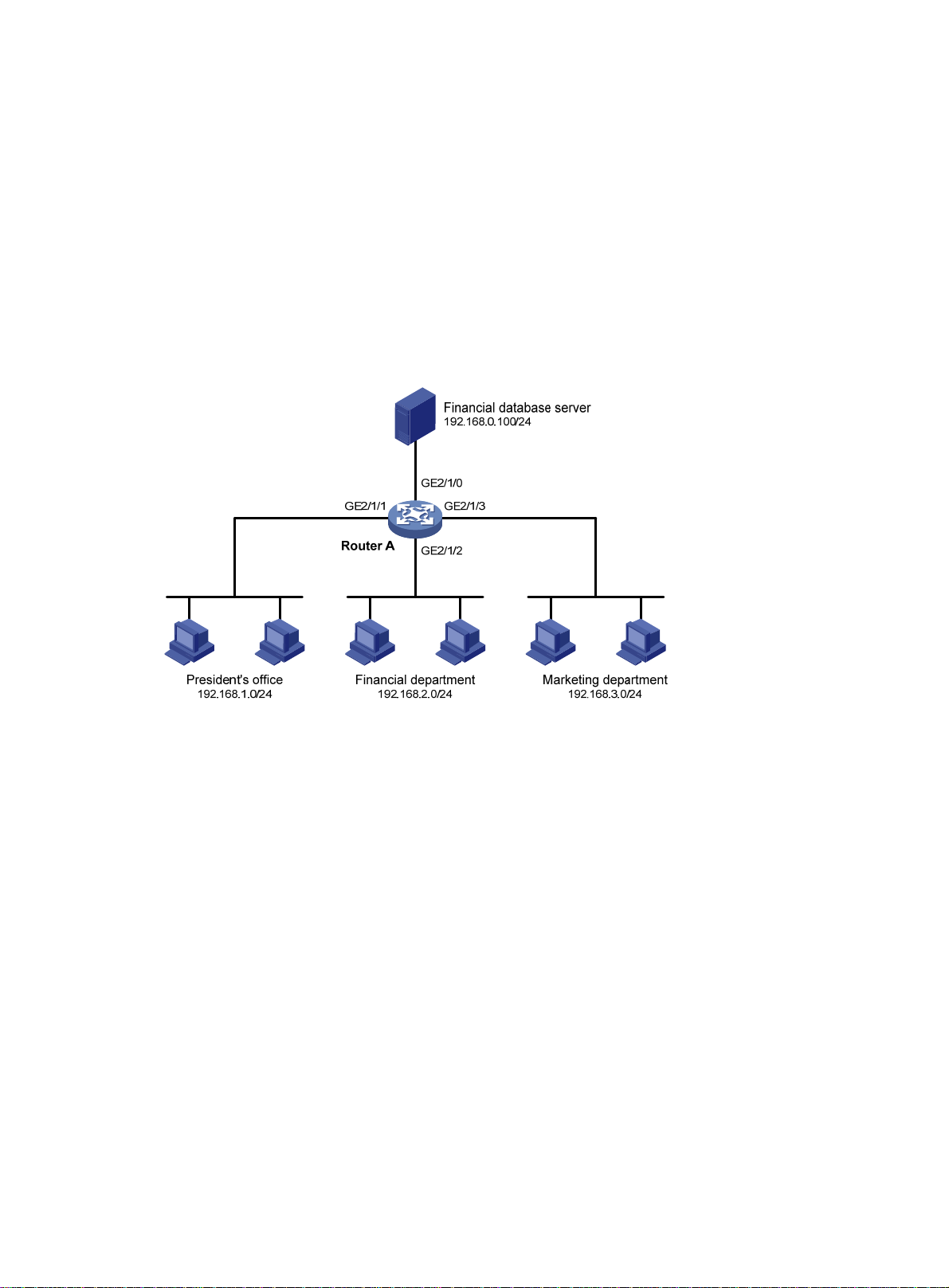
A company interconnects its departments through Router A. Configure an ACL to:
• Permit access from the President's office at any time to the financial database server.
• Permit access from the Financial department to the database server only during working hours (from
8:00 to 18:00) on working days.
• Deny access from any other department to the database server.
Figure 1 Network diagram
Configuration procedure
# Create a periodic time range from 8:00 to 18:00 on working days.
<RouterA> system-view
[RouterA] time-range work 08:0 to 18:00 working-day
# Create an IPv4 advanced ACL numbered 3000 and configure three rules in the ACL. One rule permits
access from the President's office to the financial database server, one rule permits access from the
Financial department to the database server during working hours, and one rule denies access from any
other department to the database server.
[RouterA] acl number 3000
[RouterA-acl-adv-3000] rule permit ip source 192.168.1.0 0.0.0.255 destination
192.168.0.100 0
[RouterA-acl-adv-3000] rule permit ip source 192.168.2.0 0.0.0.255 destination
192.168.0.100 0 time-range work
[RouterA-acl-adv-3000] rule deny ip source any destination 192.168.0.100 0
[RouterA-acl-adv-3000] quit
# Apply IPv4 advanced ACL 3000 to filter outgoing packets on interface GigabitEthernet 2/1/0.
[RouterA] interface gigabitethernet 2/1/0
[RouterA-GigabitEthernet2/1/0] packet-filter 3000 outbound
15
Page 18

[RouterA-GigabitEthernet2/1/0] quit
Verifying the configuration
# Ping the database server from a PC in the Financial department during the working hours. (All PCs in
this example use Windows XP).
C:\> ping 192.168.0.100
Pinging 192.168.0.100 with 32 bytes of data:
Reply from 192.168.0.100: bytes=32 time=1ms TTL=255
Reply from 192.168.0.100: bytes=32 time<1ms TTL=255
Reply from 192.168.0.100: bytes=32 time<1ms TTL=255
Reply from 192.168.0.100: bytes=32 time<1ms TTL=255
Ping statistics for 192.168.0.100:
Packets: Sent = 4, Received = 4, Lost = 0 (0% loss),
Approximate round trip times in milli-seconds:
Minimum = 0ms, Maximum = 1ms, Average = 0ms
The output shows that the database server can be pinged.
# Ping the database server from a PC in the Marketing department during the working hours.
C:\> ping 192.168.0.100
Pinging 192.168.0.100 with 32 bytes of data:
Request timed out.
Request timed out.
Request timed out.
Request timed out.
Ping statistics for 192.168.0.100:
Packets: Sent = 4, Received = 0, Lost = 4 (100% loss),
The output shows the database server cannot be pinged.
# Display configuration and match statistics for IPv4 advanced ACL 3000 on Device A during the
working hours.
[RouterA] display acl 3000
Advanced ACL 3000, named -none-, 3 rules,
ACL's step is 5
rule 0 permit ip source 192.168.1.0 0.0.0.255 destination 192.168.0.100 0
rule 5 permit ip source 192.168.2.0 0.0.0.255 destination 192.168.0.100 0 time-range work
(4 times matched) (Active)
rule 10 deny ip destination 192.168.0.100 0 (4 times matched)
The output shows that rule 5 is active. Rule 5 and rule 10 have been matched four times as the result of
the ping operations.
16
Page 19

QoS overview
In data communications, Quality of Service (QoS) provides differentiated service guarantees for
diversified traffic in terms of bandwidth, delay, jitter, and drop rate, all of which can affect QoS.
QoS manages network resources and prioritizes traffic to balance system resources.
The following section describes typical QoS service models and widely used QoS techniques.
QoS service models
This section describes several typical QoS service models.
Best-effort service model
The best-effort model is a single-service model. The best-effort model is not as reliable as other models
and does not guarantee delay-free delivery.
The best-effort service model is the default model for the Internet and applies to most network
applications. It uses the First In First Out (FIFO) queuing mechanism.
IntServ model
The integrated service (IntServ) model is a multiple-service model that can accommodate diverse QoS
requirements. This service model provides the most granularly differentiated QoS by identifying and
guaranteeing definite QoS for each data flow.
In the IntServ model, an application must request service from the network before it sends data. IntServ
signals the service request with the RSVP. All nodes receiving the request reserve resources as requested
and maintain state information for the application flow. For more information about RSVP, see MPLS
Configuration Guide.
The IntServ model demands high storage and processing capabilities because it requires all nodes along
the transmission path to maintain resource state information for each flow. This model is suitable for
small-sized or edge networks, but not large-sized networks, for example, the core layer of the Internet,
where billions of flows are present.
DiffServ model
The differentiated service (DiffServ) model is a multiple-service model that can meet diverse QoS
requirements. It is easy to implement and extend. DiffServ does not signal the network to reserve
resources before sending data, as IntServ does.
QoS techniques overview
The QoS techniques include the following functions:
17
Page 20
• Traffic classification.
• Traffic policing.
• Traffic shaping.
• Rate limit.
• Congestion management.
• Congestion avoidance.
The following section briefly introduces these QoS techniques.
All QoS techniques in this document are based on the DiffServ model.
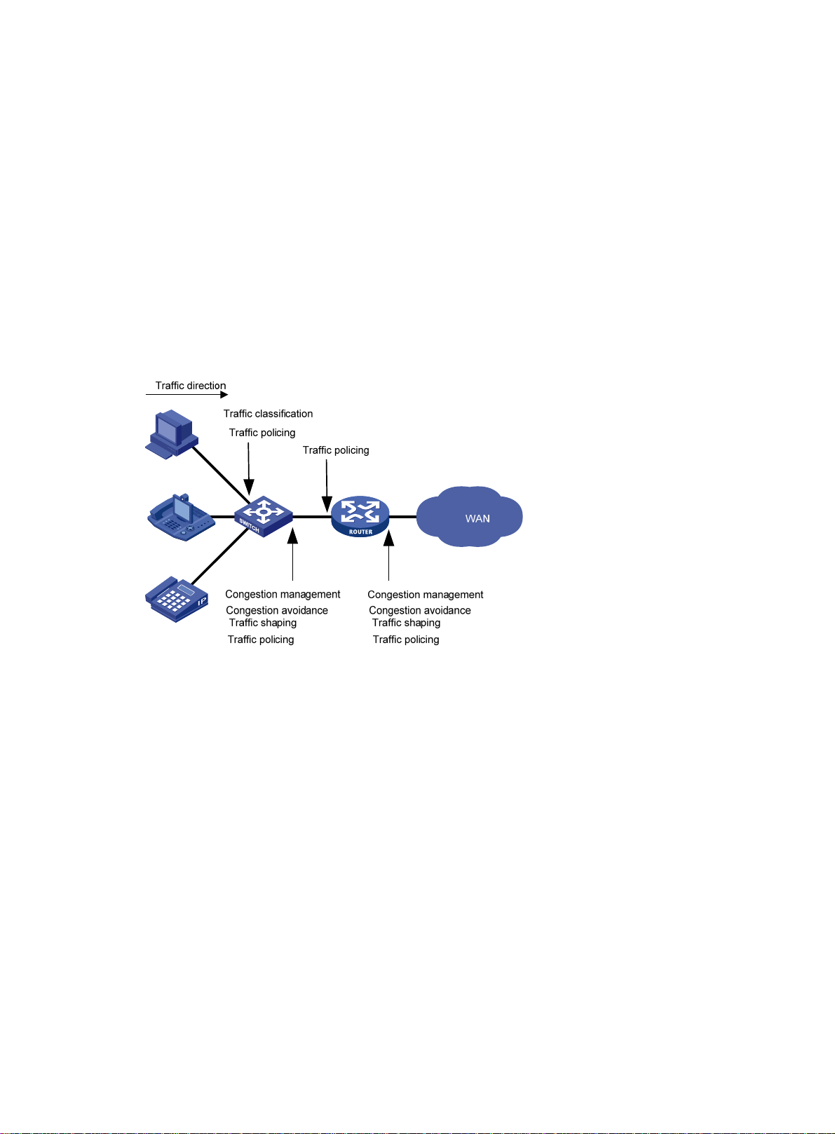
Deploying QoS in a network
Figure 2 Position of the QoS techniques in a network
As shown in Figure 2, traffic classification, traffic shaping, traffic policing, congestion management, and
congestion avoidance mainly implement the following functions:
• Traffic classification—Uses match criteria to assign packets with the same characteristics to a traffic
class. Based on traffic classes, you can provide differentiated services.
• Traffic policing—Polices flows and imposes penalties to prevent aggressive use of network resources.
You can apply traffic policing to both incoming and outgoing traffic of a port.
• Traffic shaping—Adapts the output rate of traffic to the network resources available on the
downstream device to eliminate packet drops. Traffic shaping usually applies to the outgoing traffic
of a port.
• Congestion management—Provides a resource scheduling policy to determine the packet
forwarding sequence when congestion occurs. Congestion management usually applies to the
outgoing traffic of a port.
• Congestion avoidance—Monitors the network resource usage. It is usually applied to the outgoing
traffic of a port. When congestion worsens, congestion avoidance reduces the queue length by
dropping packets.
18
Page 21
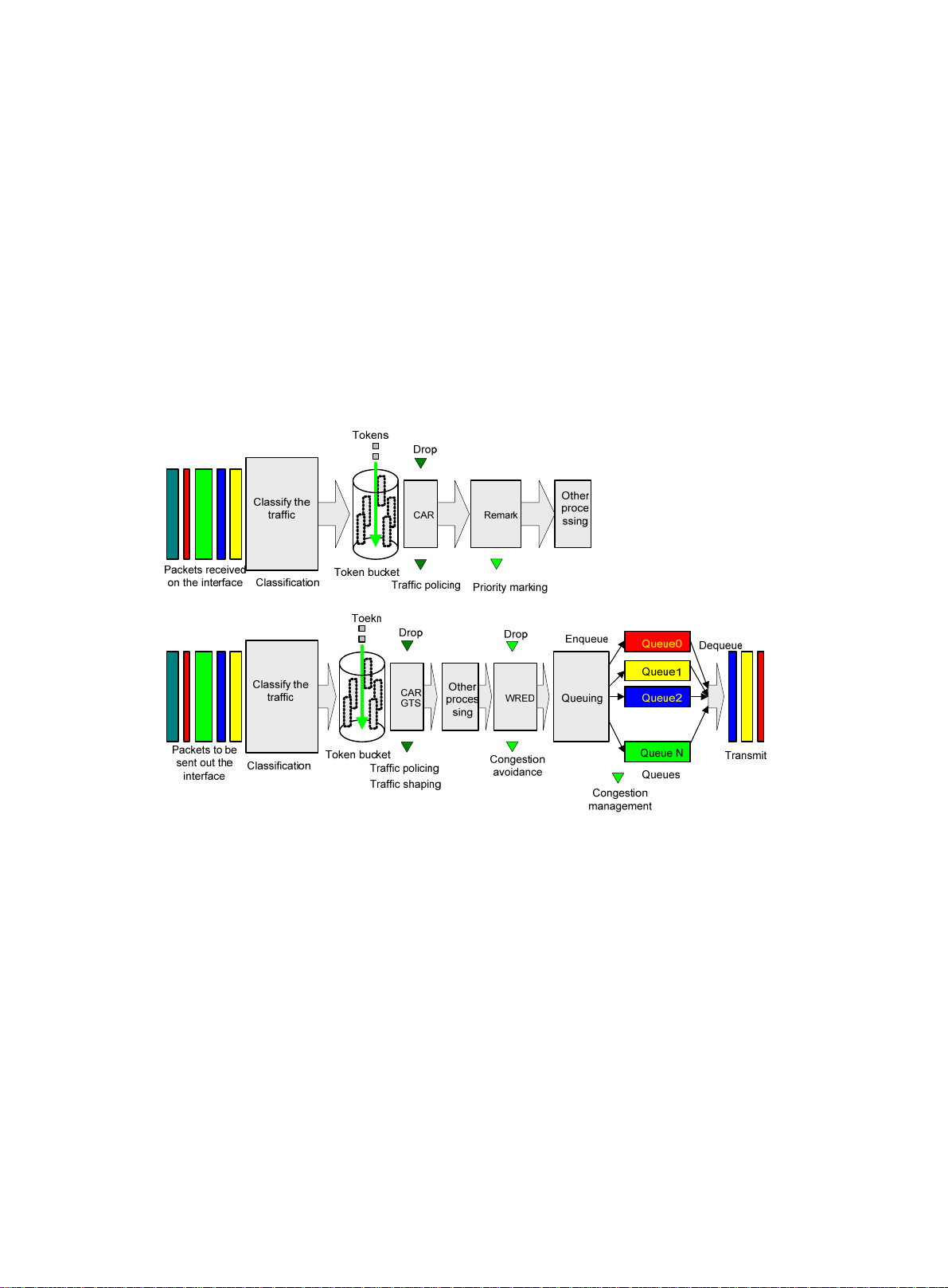
QoS processing flow in a device
Figure 3 briefly describes how the QoS module processes traffic:
1. Traffic classifier identifies and classifies traffic for subsequent QoS actions.
2. The QoS module takes various QoS actions on classified traffic as configured, depending on the
traffic processing phase and network status. For example, you can configure the QoS module to
perform the following:
{ Traffic policing for incoming traffic.
{ Traffic shaping for outgoing traffic.
{ Congestion avoidance before congestion occurs.
{ Congestion management when congestion occurs.
Figure 3 QoS processing flow
...
19
Page 22

Configuring a QoS policy
In this chapter, "MSR1000" refers to MSR1002-4. "MSR2000" refers to MSR2003, MSR2004-24,
MSR2004-48. "MSR3000" collectively refers to MSR3012, MSR3024, MSR3044, MSR3064.
"MSR4000" collectively refers to MSR4060 and MSR4080.
You can configure QoS by using the MQC approach or non-MQC approach. Some features support
both approaches, but some support only one.
Non-MQC approach
In the non-MQC approach, you configure QoS service parameters without using a QoS policy. For
example, you can use the rate limit feature to set a rate limit on an interface without using a QoS policy.
MQC approach
In the modular QoS configuration (MQC) approach, you configure QoS service parameters by using
QoS policies. A QoS policy defines the shaping, policing, or other QoS actions to take on different
classes of traffic. It is a set of class-behavior associations.
A traffic class is a set of match criteria for identifying traffic, and it uses the AND or OR operator:
• If the operator is AND, a packet must match all the criteria to match the traffic class.
• If the operator is OR, a packet matches the traffic class if it matches any of the criteria in the traffic
class.
A traffic behavior defines a set of QoS actions to take on packets, such as priority marking and redirect.
By associating a traffic behavior with a traffic class in a QoS policy, you apply the specific set of QoS
actions to the traffic class.
Configuration procedure diagram
Figure 4 shows how to configure a QoS policy.
20
Page 23

Figure 4 QoS policy configuration procedure
Defining a traffic class
Step Command
1. Enter system view.
2. Create a traffic class and
enter traffic class view.
3. Configure match criteria.
system-view N/A
traffic classifier classifier-name
[ operator { and | or } ]
if-match [ not ] match-criteria
Defining a traffic behavior
A traffic behavior is a set of QoS actions (such as traffic filtering, shaping, policing, and priority marking)
to perform on a traffic class.
To define a traffic behavior:
Step Command
1. Enter system view.
2. Create a traffic behavior and
enter traffic behavior view.
system-view N/A
traffic behavior behavior-name
Remarks
By default, no traffic class is
configured.
By default, no match criterion is
configured.
For more information, see the
if-match command in ACL and
QoS Command Reference.
Remarks
By default, no traffic behavior is
configured.
See the subsequent chapters,
3. Configure actions in the traffic
behavior.
depending on the purpose of the
traffic behavior: traffic policing,
traffic filtering, priority marking,
and so on.
21
By default, no action is configured
for a traffic behavior.
Page 24

Defining a QoS policy
Configuring a parent policy
You associate a traffic behavior with a traffic class in a QoS policy to perform the actions defined in the
traffic behavior for the traffic class of packets.
To associate a traffic class with a traffic behavior in a QoS policy:
Step Command
1. Enter system view.
2. Create a QoS policy and
enter QoS policy view.
3. Associate a traffic class with a
traffic behavior to create a
class-behavior association in
the QoS policy.
system-view N/A
qos policy policy-name
classifier classifier-name behavior
behavior-name
Configuring a child policy
You can nest a QoS policy in a traffic behavior to reclassify the traffic class associated with the behavior.
Then the actions that are defined in the QoS policy are taken on the reclassified traffic. The QoS policy
nested in the traffic behavior is called a child policy. The QoS policy that nests the behavior is called a
parent policy.
To nest QoS policies successfully, follow these guidelines:
• If class-based queuing (CBQ) is configured in a child policy, GTS must be configured in the parent
policy, and the CIR specified in GTS must be greater than or equal to CBQ bandwidth.
• If the CIR in GTS is specified as a percentage for a parent policy, the CBQ bandwidth must be
configured as a percentage for the child policy. If the CIR in GTS is specified as a value in kbps for
a parent policy, the CBQ bandwidth can be configured as a percentage or a value in kbps for the
child policy.
Remarks
By default, no QoS policy is
configured.
By default, a traffic class is not
associated with a traffic behavior.
Repeat this step to create more
class-behavior associations.
• GTS cannot be configured in the child policy.
To nest a child QoS policy in a parent QoS policy:
Step Command
1. Enter system view.
2. Create a class for the
parent policy and enter
class view.
3. Configure match criteria.
system-view N/A
traffic classifier classifier-name
[ operator { and | or } ]
if-match [ not ] match-criteria
22
Remarks
By default, no class is configured.
By default, no match criterion is
configured.
For more information about configuring
match criteria, see ACL and QoS
Command Reference.
Page 25

Step Command
4. Return to system view.
5. Create a behavior for the
parent policy and enter
behavior view.
6. Nest the child QoS
policy.
7. Return to system view.
8. Create the parent policy
and enter parent policy
view.
9. Associate the class with
the behavior in the
parent policy.
quit N/A
traffic behavior behavior-name By default, no behavior is created.
traffic-policy policy-name By default, policy nesting is not configured.
quit N/A
qos policy policy-name By default, no policy is created.
classifier classifier-name
behavior behavior-name
Applying the QoS policy
You can apply a QoS policy to the following destinations:
• Interface or PVC—The Q oS p olic y take s effect on th e tra ffic sent or re ceived on t he i nter face or P VC .
Remarks
By default, a class is not associated with a
behavior.
• Control plane—The QoS policy takes effect on the traffic received on the control plane.
• Management interface control plane—The QoS policy takes effect on the traffic sent from the
management interface to the control plane.
You can modify traffic classes, traffic behaviors, and class-behavior associations in a QoS policy even
after it is applied. If a traffic class references an ACL for traffic classification, you can delete or modify the
ACL.
Applying the QoS policy to an interface or PVC
A QoS policy can be applied to multiple interfaces or PVCs, but only one QoS policy can be applied to
one direction (inbound or outbound) of an interface or PVC.
The QoS policy applied to the outgoing traffic on an interface or PVC does not regulate local packets,
which are critical protocol packets sent by the local system for operation maintenance. The most common
local packets include link maintenance, routing, LDP, RSVP, and SSH packets.
To apply the QoS policy to an interface or PVC:
Step Command
1. Enter system view.
system-view N/A
• Enter interface view:
interface interface-type
2. Enter interface or PVC
view.
interface-number
• Enter PVC view:
a. interface atm interface-number
b. pvc vpi/vci
Remarks
Settings in interface view take
effect on the current interface.
Settings in PVC view take
effect on the current PVC.
23
Page 26

3. Apply the QoS policy to
the interface or PVC.
qos apply policy policy-name { inbound |
outbound }
Applying the QoS policy to the control plane
A device provides the data plane and the control plane:
• Data plane—The units at the data plane are responsible for receiving, transmitting, and switching
(forwarding) packets, such as various dedicated forwarding chips. They deliver super processing
speeds and throughput.
• Control plane—The units at the control plane are processing units running most routing and
switching protocols. They are responsible for protocol packet resolution and calculation, such as
CPUs. Compared with data plane units, the control plane units allow for great packet processing
flexibility but have lower throughput.
When the data plane receives packets that it cannot recognize or process, it transmits them to the control
plane. If the transmission rate exceeds the processing capability of the control plane, the control plane
will be busy handling undesired packets and fail to handle legitimate packets correctly or timely. As a
result, protocol performance is affected.
To address this problem, apply a QoS policy to the control plane to take QoS actions, such as traffic
filtering or rate limiting, on inbound traffic. This makes sure the control plane can correctly receive,
transmit, and process packets.
By default, no QoS policy is
applied to an interface or
PVC.
The router is enabled with predefined control plane QoS policies by default. A predefined control plane
QoS policy uses the protocol type or protocol group type to identif y the t yp e of packets s ent to the control
plane. You can reference protocol types or protocol group types in if-match commands in traffic class
view for traffic classification. Then you can reconfigure traffic behaviors for these traffic classes as
required. You can use the display qos policy control-plane pre-defined command to display predefined
control plane QoS policies.
If the hardware resources of an interface card are insufficient, applying a QoS policy to the control plane
might fail on the interface card. The system does not automatically roll back the QoS policy already
applied to the MPU or other interface cards. To ensure consistency, you must use the undo qos apply
policy command to manually remove the QoS policy configuration applied to them.
Configuration procedure
To apply the QoS policy to the control plane:
Step Command
1. Enter system view.
2. Enter control plane view.
3. Apply the QoS policy to
the control plane.
Remarks
system-view N/A
• MSR1000/MSR2000/MSR3000:
control-plane
• MSR4000:
control-plane slot slot-number
qos apply policy policy-name inbound
N/A
By default, no QoS policy is
applied to a control plane.
24
Page 27

y
Applying the QoS policy to the management interface control plane
The following matrix shows the feature and hardware compatibility:
Hardware Feature compatibilit
MSR1000 No
MSR2000 No
MSR3000 No
MSR4000 Yes
If the transmission rate of the packets sent from the management interface to the control plane exceeds
the processing capability of the control plane, the control plane will fail to handle the packets correctly
or timely. As a result, protocol performance is affected.
To address this problem, apply a rate-limiting QoS policy to the packets sent from the management
interface to the control plane. This makes sure the control plane can correctly receive, transmit, and
process packets from the management interface.
By default, the management interface is enabled with predefined rate-limiting QoS policies by default. A
predefined rate-limiting QoS policy uses the protocol type or protocol group type to identify the type of
packets sent to the management interface. You can reference protocol types or protocol group types in
if-match commands in traffic class view for traffic classification and then reconfigure traffic behaviors for
these traffic classes as required. You can use the display qos policy control-plane management
pre-defined command to display the traffic behaviors.
To apply the QoS policy to the management interface control plane:
Step Command
1. Enter system view.
2. Enter management
interface control plane
view.
3. Apply the QoS policy to
the management
interface control plane.
system-view N/A
control-plane management N/A
qos apply policy policy-name inbound
Remarks
By default, no QoS policy is
applied to the management
interface control plane.
Configuring the QoS policy-based traffic rate statistics collection period for an interface
You can enable collection of per-class traffic statistics over a period of time, including the average
forwarding rate and drop rate. For example, if you set the statistics collection period to n minutes, the
system collects traffic statistics for the most recent n minutes and refreshes the statistics every 10/n minutes.
You can use the display qos policy interface command to view the collected traffic rate statistics.
To configure the QoS policy-based traffic rate statistics collection period for an interface:
25
Page 28

Step Command
1. Enter system view.
2. Enter interface view.
3. Configure the traffic rate
statistics collection period
for the interface.
system-view N/A
interface interface-type interface-number N/A
qos flow-interval interval
Remarks
The default setting is 5 minutes.
A subinterface uses the statistics
collection period configured on
the main interface.
A PVC uses the statistics
collection period configured on
the ATM main interface.
Displaying and maintaining QoS policies
Execute display commands in any view and reset commands in user view.
Task Command
Display traffic class configuration
(MSR1000/MSR2000/MSR3000).
Display traffic class configuration
(MSR4000).
display traffic classifier { system-defined | user-defined }
[ classifier-name ]
display traffic classifier { system-defined | user-defined }
[ classifier-name ] [ slot slot-number ]
Display traffic behavior configuration
(MSR1000/MSR2000/MSR3000).
Display traffic behavior configuration
(MSR4000).
Display QoS policy configuration
(MSR1000/MSR2000/MSR3000).
Display QoS policy configuration
(MSR4000).
Display information about QoS policies
applied to interfaces
(MSR1000/MSR2000/MSR3000).
Display information about QoS policies
applied to interfaces (MSR4000).
Display information about QoS policies
applied to the control plane
(MSR1000/MSR2000/MSR3000).
Display information about QoS policies
applied to a control plane (MSR4000).
Display information about QoS policies
applied to the management interface
control plane (MSR4000).
display traffic behavior { system-defined | user-defined }
[ behavior-name ]
display traffic behavior { system-defined | user-defined }
[ behavior-name ] [ slot slot-number ]
display qos policy { system-defined | user-defined } [ policy-name
[ classifier classifier-name ] ]
display qos policy { system-defined | user-defined } [ policy-name
[ classifier classifier-name ] ] [ slot slot-number ]
display qos policy interface [ interface-type interface-number [ pvc
{ pvc-name | vpi/vci } ] ] [ inbound | outbound ]
display qos policy interface [ interface-type interface-number [ pvc
{ pvc-name | vpi/vci } ] ] [ slot slot-number ] [ inbound | outbound ]
display qos policy control-plane
display qos policy control-plane slot slot-number
display qos policy control-plane management
Display information about the predefined
QoS policy applied to the control plane
(MSR1000/MSR2000/MSR3000).
display qos policy control-plane pre-defined
26 27
Page 29

Display information about the predefined
QoS policy applied to a control plane
(MSR4000).
Display information about the predefined
QoS policy applied to the management
interface control plane (MSR4000).
Clear the statistics for the QoS policy
applied to the control plane
(MSR1000/MSR2000/MSR3000).
display qos policy control-plane pre-defined [ slot slot-number ]
display qos policy control-plane management pre-defined
reset qos policy control-plane
Clear the statistics for the QoS policy
applied to a control plane (MSR4000).
Clear the statistics for the QoS policy
applied to the management interface
control plane (MSR4000).
reset qos policy control-plane slot slot-number
reset qos policy control-plane management
Page 30

Configuring priority mapping
Overview
When a packet arrives, a device assigns a set of QoS priority parameters to the packet based on either
a priority field carried in the packet or the port priority of the incoming port. This process is called
"priority mapping." During this process, the device can modify the priority of the packet according to the
priority mapping rules. The set of QoS priority parameters decides the scheduling priority and
forwarding priority of the packet.
Priority mapping is implemented with priority maps and involves the following priorities:
• 802.1p priority.
• DSCP.
• EXP.
• IP precedence.
• Local precedence.
Introduction to priorities
Priorities include the following types: priorities carried in packets, and priorities locally assigned for
scheduling only.
Packet-carried priorities include 802.1p priority, DSCP precedence, IP precedence, and EXP. These
priorities have global significance and affect the forwarding priority of packets across the network. For
more information about these priorities, see "Appendixes."
Locally assigned priorities only have local significance. They are assigned by the device only for
scheduling. These priorities include the local precedence, drop priority, and user priority, as follows:
• Local precedence—Used for queuing. A local precedence value corresponds to an output queue. A
packet with higher local precedence is assigned to a higher priority output queue to be
preferentially scheduled.
• User priority—Precedence that the device automatically extracts from a priority field of the packet
according to its forwarding path. It is a parameter for determining the scheduling priority and
forwarding priority of the packet. The user priority represents:
{ The 802.1p priority for Layer 2 packets.
{ The IP precedence for Layer 3 packets.
{ The EXP for MPLS packets.
Priority maps
The device provides various types of priority maps. By looking through a priority map, the device decides
which priority value to assign to a packet for subsequent packet processing.
28
Page 31

The default priority maps (as shown in Appendix B Default uncolored priority maps) are available for
priority mapping. They are adequate in most cases. If a default priority map cannot meet your
requirements, you can modify the priority map as required.
Priority mapping configuration tasks
You can configure priority mapping by using any of the following methods:
• Configuring priority trust mode—In this method, you can configure a port to look up a trusted
priority type (802.1p, for example) in incoming packets in the priority maps. Then, the system maps
the trusted priority to the target priority types and values.
• Changing port priority—If no packet priority is trusted, the port priority of the incoming port is used.
By changing the port priority of a port, you change the priority of the incoming packets on the port.
To configure priority mapping, perform the following tasks:
Tasks at a glance
(Optional.) Configuring an uncolored priority map
(Required.) Perform one of the following tasks:
• Configuring a port to trust packet priority for priority mapping
• Changing the port priority of an interface错误!未找到引用源。
Configuring an uncolored priority map
The router provides the following types of priority map:
Priority map Description
dot1p-lp 802.1p-local priority map.
dscp-lp DSCP-local priority map.
To configure an uncolored priority map:
Step Command
1. Enter system view.
2. Enter priority map view.
3. Configure mappings for the
priority map.
system-view N/A
qos map-table { dot1p-lp | dscp-lp } N/A
import import-value-list export export-value
Remarks
By default, the default
priority maps are used.
For more information, see
"Appendix B Default
uncolored priority maps."
Newly configured
mappings overwrite the
old ones.
29
Page 32

Configuring a port to trust packet priority for priority mapping
This feature is supported only on routers installed with Layer 2 switching modules. For information about
interface modules, see HP MSR Series Routers Interface Module Manual.
You can configure the device to trust a particular priority field carried in packets for priority mapping on
ports or globally.
When you configure the trusted packet priority type on an interface, use the following available
keywords:
• dot1p—Uses the 802.1p priority of received packets for mapping.
• dscp—Uses the DSCP precedence of received IP packets for mapping.
To configure the trusted packet priority type on an interface:
Step Command
1. Enter system view.
2. Enter interface view.
3. Configure the trusted
packet priority type.
system-view N/A
interface interface-type
interface-number
qos trust { dot1p | dscp } By default, the port priority is trusted.
Remarks
N/A
Changing the port priority of an interface
If an interface does not trust any packet priority, the device uses its port priority to look for the set of
priority parameters for the incoming packets. By changing port priority, you can prioritize traffic received
on different interfaces.
To change the port priority of an interface:
Step Command
1. Enter system view.
2. Enter interface view.
3. Set the port priority of
the interface.
system-view N/A
interface interface-type interface-number N/A
qos priority priority-value The default setting is 0.
Remarks
Displaying and maintaining priority mapping
Execute display commands in any view.
30
Page 33

Task Command
Display priority map configuration.
Display the trusted packet priority type
on a port.
display qos map-table [ dot1p-lp | dscp-lp ]
display qos trust interface [ interface-type interface-number ]
Port priority configuration example
Network requirements
As shown in Figure 5, the IP precedence of traffic from Router A to Router C is 3, and the IP precedence
of traffic from Router B to Router C is 1.
Configure Router C to preferentially process packets from Router A to the server when GigabitEthernet
2/1/2 of Router C is congested.
Figure 5 Network diagram
G
E
2
/
I
1
P
/
0
p
r
e
c
e
d
e
n
c
e
3
G
E
2
/
1
/
0
1
/
1
/
2
GE
1
e
c
1
/
n
1
e
/
d
2
e
E
c
e
G
r
p
P
I
Configuration procedure
# Assign port priority to GigabitEthernet 2/1/0 and GigabitEthernet 2/1/1. Make sure the priority of
GigabitEthernet 2/1/0 is higher than that of GigabitEthernet 2/1/1, and no trusted packet priority type
is configured on GigabitEthernet 2/1/0 or GigabitEthernet 2/1/1.
<RouterC> system-view
[RouterC] interface gigabitethernet 2/1/0
[RouterC-GigabitEthernet2/1/0] qos priority 3
[RouterC-GigabitEthernet2/1/0] quit
[RouterC] interface gigabitethernet 2/1/1
[RouterC-GigabitEthernet2/1/1] qos priority 1
[RouterC-GigabitEthernet2/1/1] quit
31
Page 34

g p
y
Priority mapping table and priority marking configuration example
Network requirements
As shown in Figure 6:
• The marketing department connects to GigabitEthernet 2/1/0 of the router, which sets the 802.1p
priority of traffic from the marketing department to 3.
• The R&D department connects to GigabitEthernet 2/1/1 of the router, which sets the 802.1p
priority of traffic from the R&D department to 4.
• The management department connects to Ethernet 2/1/2 of the router, which sets the 802.1p
priority of traffic from the management department to 5.
Configure port priority, 802.1p-to-local mapping table, and priority marking to implement the plan as
described in Table 2.
Table 2 Configuration plan
Traffic
destination
Public servers
Internet
Traffic priority order
R&D department >
management
department > marketing
department
Management
department > marketing
department > R&D
department
Queuin
Traffic source
R&D department 6 High
Management
department
Marketing department 2 Low
R&D department 2 Low
Management
department
Marketing department 3 Medium
lan
Output queue Queue priorit
4 Medium
6 High
32
Page 35
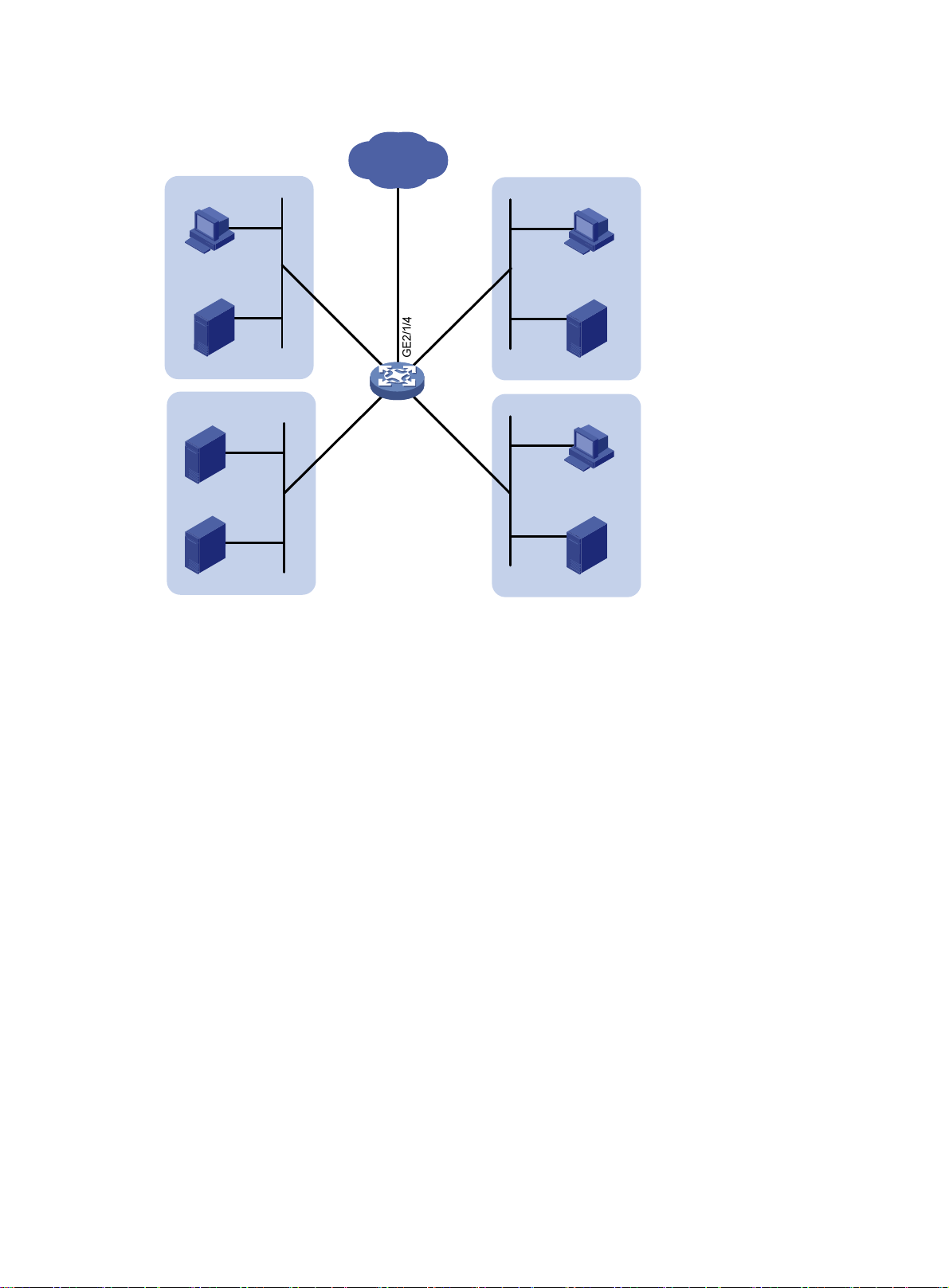
Figure 6 Network diagram
Internet
Host
Server
Management Dept
Data server
Mail server
Public servers
GE2/1
/1/3
E2
G
/2
Router
GE2/1/1
GE2/1/
Host
Server
R&D Dept
0
Marketing Dept
Host
Server
Configuration procedure
1. Configure trusting port priority:
# Set the port priority of GigabitEthernet 2/1/0 to 3.
<Router> system-view
[Router] interface gigabitethernet 2/1/0
[Router-GigabitEthernet2/1/0] qos priority 3
[Router-GigabitEthernet2/1/0] quit
# Set the port priority of GigabitEthernet 2/1/1 to 4.
[Router] interface gigabitethernet 2/1/1
[Router-GigabitEthernet2/1/1] qos priority 4
[Router-GigabitEthernet2/1/1] quit
# Set the port priority of GigabitEthernet 2/1/2 to 5.
[Router] interface gigabitethernet 2/1/2
[Router-GigabitEthernet2/1/2] qos priority 5
[Router-GigabitEthernet2/1/2] quit
2. Configure the 802.1p-to-local mapping table to map 802.1p priority values 3, 4, and 5 to local
precedence values 2, 6, and 4.
This guarantees the R&D department, management department, and marketing department
decreased priorities to access the public servers.
[Router] qos map-table dot1p-lp
[Router-maptbl-dot1p-lp] import 3 export 2
[Router-maptbl-dot1p-lp] import 4 export 6
33 34
Page 36

[Router-maptbl-dot1p-lp] import 5 export 4
[Router-maptbl-dot1p-lp] quit
3. Map the local precedence values 6 and 2 to local precedence values 2 and 3 and keep local
precedence value 4 unchanged.
This guarantees the management department, marketing department, and R&D department
decreased priorities to access the Internet.
[Router] traffic classifier rd
[Router-classifier-rd] if-match local-precedence 6
[Router-classifier-rd] quit
[Router] traffic classifier market
[Router-classifier-market] if-match local-precedence 2
[Router-classifier-market] quit
[Router] traffic behavior rd
[Router-behavior-rd] remark local-precedence 2
[Router-behavior-rd] quit
[Router] traffic behavior market
[Router-behavior-market] remark local-precedence 3
[Router-behavior-market] quit
[Router] qos policy policy1
[Router-qospolicy-policy1] classifier rd behavior rd
[Router-qospolicy-policy1] classifier market behavior market
[Router-qospolicy-policy1] quit
[Router] interface gigabitethernet 2/1/4
[Router-GigabitEthernet2/1/4] qos apply policy policy1 outbound
Page 37

Configuring traffic policing, GTS, and rate limit
In this chapter, "MSR1000" refers to MSR1002-4. "MSR2000" refers to MSR2003, MSR2004-24,
MSR2004-48. "MSR3000" collectively refers to MSR3012, MSR3024, MSR3044, MSR3064.
"MSR4000" collectively refers to MSR4060 and MSR4080.
Overview
Traffic policing helps assign network resources (including bandwidth) and increase network performance.
For example, you can configure a flow to use only the resources committed to it in a certain time range.
This avoids network congestion caused by burst traffic.
Traffic policing, Generic Traffic Shaping (GTS), and rate limit control the traffic rate and resource usage
according to traffic specifications. You can use token buckets for evaluating traffic specifications.
Traffic evaluation and token buckets
Token bucket features
A token bucket is analogous to a container that holds a certain number of tokens. Each token represents
a certain forwarding capacity. The system puts tokens into the bucket at a constant rate. When the token
bucket is full, the extra tokens cause the token bucket to overflow.
Evaluating traffic with the token bucket
A token bucket mechanism evaluates traffic by looking at the number of tokens in the bucket. If the
number of tokens in the bucket is enough for forwarding the packets, the traffic conforms to the
specification (called "conforming traffic"), and the corresponding tokens are taken away from the bucket.
Otherwise, the traffic does not conform to the specification (called "excess traffic").
A token bucket has the following configurable parameters:
• Mean rate at which tokens are put into the bucket, which is the permitted average rate of traffic. It
is usually set to the committed information rate (CIR).
• Burst size or the capacity of the token bucket. It is the maximum traffic size permitted in each burst.
It is usually set to the committed burst size (CBS). The set burst size must be greater than the
maximum packet size.
Each arriving packet is evaluated.
Complicated evaluation
You can set two token buckets, bucket C and bucket E, to evaluate traffic in a more complicated
environment and achieve more policing flexibility. For example, traffic policing uses the following
parameters:
• CIR—Rate at which tokens are put into bucket C. It sets the average packet transmission or
forwarding rate allowed by bucket C.
• CBS—Size of bucket C, which specifies the transient burst of traffic that bucket C can forward.
• PIR—Rate at which tokens are put into bucket E, which specifies the average packet transmission or
forwarding rate allowed by bucket E.
35
Page 38

• EBS—Size of bucket E, which specifies the transient burst of traffic that bucket E can forward.
CBS is implemented with bucket C, and EBS with bucket E. In each evaluation, packets are measured
against the following bucket scenarios:
• If bucket C has enough tokens, packets are colored green.
• If bucket C does not have enough tokens but bucket E has enough tokens, packets are colored
yellow.
• If neither bucket C nor bucket E has sufficient tokens, packets are colored red.
Traffic policing
Traffic policing supports policing the inbound traffic and the outbound traffic.
A typical application of traffic policing is to supervise the specification of traffic entering a network and
limit it within a reasonable range. Another application is to "discipline" the extra traffic to prevent
aggressive use of network resources by an application. For example, you can limit bandwidth for HTTP
packets to less than 50% of the total. If the traffic of a session exceeds the limit, traffic policing can drop
the packets or reset the IP precedence of the packets. Figure 7 shows an example of policing outbound
traffic on an interface.
Figure 7 Traffic policing
Traffic policing is widely used in policing traffic entering the ISP networks. It can classify the policed traffic
and take predefined policing actions on each packet depending on the evaluation result:
• Forwarding the packet if the evaluation result is "conforming."
• Dropping the packet if the evaluation result is "excess."
• Forwarding the packet with its precedence re-marked if the evaluation result is "conforming."
• Delivering the packet to next-level traffic policing with its precedence re-marked if the evaluation
result is "conforming."
• Entering the next-level policing (you can set multiple traffic policing levels each focused on objects
at different levels).
36
Page 39

GTS
GTS supports shaping the outbound traffic. GTS limits the outbound traffic rate by buffering exceeding
traffic. You can use GTS to adapt the traffic output rate on a device to the input traffic rate of its connected
device to avoid packet loss.
The differences between traffic policing and GTS are as follows:
• Packets to be dropped with traffic policing are retained in a buffer or queue with GTS, as shown
in Figure 8. When enough tokens are in the token bucket, the buffered packets are sent at an even
rate.
• GTS can result in additional delay and traffic policing does not.
Figure 8 GTS
For example, in Figure 9, Router B performs traffic policing on packets from Router A and drops packets
exceeding the limit. To avoid packet loss, you can perform GTS on the outgoing interface of Router A so
that packets exceeding the limit are cached in Router A. Once resources are released, GTS takes out the
cached packets and sends them out.
Figure 9 GTS application
Router A
Rate limit
Rate limit controls the rate of inbound and outbound traffic. The outbound traffic is taken for example.
The rate limit of a physical interface specifies the maximum rate for forwarding packets (including critical
packets).
Physical link
Router B
37
Page 40

Rate limit also uses token buckets for traffic control. When rate limit is configu red on an interface, a token
bucket handles all packets to be sent through the interface for rate limiting. If enough tokens are in the
token bucket, packets can be forwarded. Otherwise, packets are put into QoS queues for congestion
management. In this way, the traffic passing the physical interface is controlled.
Figure 10 Rate limit implementation
The token bucket mechanism limits traffic rate when accommodating bursts. It allows bursty traffic to be
transmitted if enough tokens are available. If tokens are scarce, packets cannot be transmitted until
efficient tokens are generated in the token bucket. It restricts the traffic rate to the rate for generating
tokens.
Rate limit controls the total rate of all packets on a physical interface. It is easier to use than traffic policing
in controlling the total traffic rate on a physical interface.
Configuring traffic policing
You can configure traffic policing by using the MQC approach or non-MQC approach. If traffic policing
is configured by using both the MQC approach and non-MQC approach, the configuration in MQC
approach takes effect.
Configuring traffic policing by using the MQC approach
Step Command
1. Enter system view.
2. Create a traffic class
and enter traffic class
view.
system-view N/A
traffic classifier classifier-name
[ operator { and | or } ]
Remarks
By default, no traffic class is
configured.
By default, no match criterion is
3. Configure match
criteria.
4. Return to system view.
if-match [ not ] match-criteria
quit N/A
38
configured.
For more information about the
if-match command, see ACL and QoS
Command Reference.
Page 41

Step Command
5. Create a traffic
behavior and enter
traffic behavior view.
6. Configure a traffic
policing action.
7. Return to system view.
8. Create a QoS policy
and enter QoS policy
view.
9. Associate the traffic
class with the traffic
behavior in the QoS
policy.
10. Return to system view.
traffic behavior behavior-name
car cir committed-information-rate [ cbs
committed-burst-size [ ebs
excess-burst-size ] ] [ pir
peak-information-rate ] [ green action |
red action | yellow action ] *
quit N/A
qos policy policy-name
classifier classifier-name behavior
behavior-name
quit N/A
• Applying the QoS policy to an
interface or PVC
• Applying the QoS policy to the
11. Apply the QoS policy.
control plane
• Applying the QoS policy to the
management interface control
plane
12. (Optional.) Display
traffic policing
configuration.
display qos policy user-defined
[ policy-name ]
Remarks
By default, no traffic behavior is
configured.
By default, no traffic policing action is
configured.
By default, no QoS policy is
configured.
By default, a traffic class is not
associated with a traffic behavior.
Choose one of the application
destinations as needed.
By default, no QoS policy is applied.
Available in any view.
Configuring traffic policing by using the non-MQC approach
Configuring CAR-list-based traffic policing
Step Command
1. Enter system view.
2. Configure a CAR list.
3. Enter interface view.
system-view N/A
qos carl carl-index { dscp dscp-list | mac
mac-address | mpls-exp mpls-exp-value |
precedence precedence-value |
{ destination-ip-address |
source-ip-address } { range start-ip-address to
end-ip-address | subnet ip-address
mask-length } [ per-address
[ shared-bandwidth ] ] }
interface interface-type interface-number N/A
39
Remarks
By default, no CAR list is
configured.
Page 42

Step Command
qos car { inbound | outbound } carl
4. Configure a
CAR-list-based CAR
policy on the interface.
carl-index cir committed-information-rate [ cbs
committed-burst-size [ ebs excess-burst-size ] ]
[ pir peak-information-rate ] [ green action |
red action | yellow action ] *
Configuring ACL-based traffic policing
Step Command
1. Enter system view.
2. Enter interface view.
3. Configure an
ACL-based CAR
policy on the
interface.
system-view N/A
interface interface-type interface-number N/A
qos car { inbound | outbound } acl [ ipv6 ]
acl-number cir committed-information-rate
[ cbs committed-burst-size [ ebs
excess-burst-size ] ] [ pir
peak-information-rate ] [ green action |
red action | yellow action ] *
Configuring traffic policing for all traffic
Step Command
1. Enter system view.
system-view N/A
Remarks
By default, no CAR policy is
configured.
Remarks
By default, no CAR policy is
configured on an interface.
Remarks
2. Enter interface view.
3. Configure a CAR
policy for all traffic on
the interface.
interface interface-type interface-number N/A
qos car { inbound | outbound } any cir
committed-information-rate [ cbs
committed-burst-size [ ebs
excess-burst-size ] ] [ pir
peak-information-rate ] [ green action |
red action | yellow action ] *
By default, no CAR policy is
configured on an interface.
Configuring GTS
You can configure GTS by using either the MQC approach or non-MQC approach.
Configuring GTS by using the MQC approach
Step Command
1. Enter system view.
2. Create a class and
enter class view.
system-view N/A
traffic classifier classifier-name [ operator
{ and | or } ]
Remarks
By default, no class is created.
40
Page 43

Step Command
3. Configure match
criteria.
4. Return to system view.
5. Create a behavior and
enter behavior view.
6. Configure a GTS
action.
7. Return to system view.
8. Create a QoS policy
and enter policy view.
if-match [ not ] match-criteria
quit N/A
traffic behavior behavior-name
• In absolute value:
gts cir committed-information-rate [ cbs
committed-burst-size [ ebs
excess-burst-size ] ] [ queue-length
queue-length ]
• In percentage:
gts percent cir cir-percent [ cbs cbs-time
[ ebs ebs-time ] ] [ queue-length
queue-length ]
quit
qos policy policy-name
Remarks
By default, no match criterion
is configured.
For configurable match
criteria, see the if-match
command in ACL and QoS
Command Reference.
By default, no behavior is
created.
By default, no GTS action is
configured.
N/A
By default, no QoS policy is
created.
9. Associate the class with
the traffic behavior in
the QoS policy.
10. Return to system view.
11. Apply the QoS policy.
12. (Optional.) Display
traffic behavior
configuration.
classifier classifier-name behavior
behavior-name
quit N/A
• Applying the QoS policy to an interface or
PVC
• Applying the QoS policy to the control
plane
display qos policy user-defined
[ policy-name ]
By default, a traffic class is not
associated with a traffic
beha or.
vi
By default, a QoS policy is not
applied.
Choose one of the application
destinations as needed.
Available in any view.
Configuring GTS by using the non-MQC approach
You can configure the following types of GTS when using the non-MQC approach:
• ACL-based GTS—Configures GTS parameters for traffic matching a specific ACL. By specifying
multiple ACLs, you can set GTS parameters for traffic of different traffic classes.
• GTS for all traffic—Configures GTS parameters for all traffic.
Configuring ACL-based GTS
Step Command
1. Enter system view.
2. Enter interface view.
system-view N/A
interface interface-type interface-number N/A
41
Remarks
Page 44

3. Configure ACL-based
GTS on the interface.
Configuring GTS for all traffic
qos gts acl [ ipv6 ] acl-number cir
committed-information-rate [ cbs
committed-burst-size [ ebs
excess-burst-size ] ] [ queue-length
queue-length ]
By default, GTS is not configured
on an interface.
Step Command
1. Enter system view.
2. Enter interface view.
3. Configure GTS on the
interface.
system-view N/A
interface interface-type interface-number N/A
qos gts any cir committed-information-rate
[ cbs committed-burst-size [ ebs
excess-burst-size ] ] [ queue-length
queue-length ]
Configuring the rate limit
The rate limit of a physical interface specifies the maximu m rate of i nco min g packets o r ou tgoi ng packets .
To configure the rate limit:
Step Command
1. Enter system view.
2. Enter interface view.
3. Configure the rate limit
for the interface.
system-view N/A
interface interface-type interface-number N/A
qos lr { inbound | outbound } cir
committed-information-rate [ cbs
committed-burst-size [ ebs
excess-burst-size ] ]
Remarks
By default, GTS is not configured
on an interface.
Remarks
By default, rate limit is not
configured on an interface.
Displaying and maintaining traffic policing, GTS, and rate limit
Execute display commands in any view.
Task Command
Display CAR configuration and statistics on
an interface.
Display CAR lists
(MSR1000/MSR2000/MSR3000).
Display CAR lists (MSR4000). display qos carl [ carl-index ] [ slot slot-number ]
Display traffic policing configuration. display qos policy user-defined [ policy-name ]
display qos car interface [ interface-type interface-number ]
display qos carl [ carl-index ]
42
Page 45

Task Command
Display GTS configuration and statistics on
an interface.
Display rate limit configuration and statistics
on an interface.
display qos gts interface [ interface-type interface-number ]
display qos lr interface [ interface-type interface-number ]
Traffic policing and GTS configuration example
Network requirements
As shown in Figure 11:
• The server, Host A, and Host B can access the Internet through Router A and Router B.
• The server, Host A, and GigabitEthernet 2/1/0 of Router A are in the same network segment.
• Host B and GigabitEthernet 2/1/1 of Router A are in the same network segment.
Perform traffic control for the packets GigabitEthernet 2/1/0 of Router A receives from the server and
Host A, as follows:
• Limit the rate of packets from the server to 54 kbps. When the traffic rate is below 54 kbps, the
traffic is forwarded. When the traffic rate exceeds 54 kbps, the excess packets are marked with IP
precedence 0 and then forwarded.
• Limit the rate of packets from Host A to 8 kbps. When the traffic rate is below 8 kbps, the traffic is
forwarded. When the traffic rate exceeds 8 kbps, the excess packets are dropped.
Perform traffic control on GigabitEthernet 2/1/0 and GigabitEthernet 2/1/1 of Router B, as follows:
• Limit the incoming traffic rate on GigabitEthernet 2/1/0 to 500 kbps, and the excess packets are
dropped.
• Limit the outgoing traffic rate on GigabitEthernet 2/1/1 to 1000 kbps, and the excess packets are
dropped.
Figure 11 Network diagram
Server
1.1.1.1/8 1.1.1.2/8
Ethernet
Host A
GE1/1/0
Router A
GE2/1/1
Router B
GE2/1/0
Host B
GE2/1/2
Internet
GE2/1/1
Configuration procedure
1. Configure Router A:
43
Page 46

# Configure GTS on GigabitEthernet 2/1/2, shaping the packets when the sending rate exceeds
500 kbps to decrease the packet loss rate of GigabitEthernet 2/1/0 of Router B.
<RouterA> system-view
[RouterA] interface gigabitethernet 2/1/2
[RouterA-GigabitEthernet2/1/2] qos gts any cir 500
[RouterA-GigabitEthernet2/1/2] quit
# Configure ACLs to permit the packets from the server and Host A.
[RouterA] acl number 2001
[RouterA-acl-basic-2001] rule permit source 1.1.1.1 0
[RouterA-acl-basic-2001] quit
[RouterA] acl number 2002
[RouterA-acl-basic-2002] rule permit source 1.1.1.2 0
[RouterA-acl-basic-2002] quit
# Configure CAR policies for different flows received on GigabitEthernet 2/1/0.
[RouterA] interface gigabitethernet 2/1/0
[RouterA-GigabitEthernet2/1/0] qos car inbound acl 2001 cir 54 cbs 4000 ebs 0 green
pass red remark-prec-pass 0
[RouterA-GigabitEthernet2/1/0] qos car inbound acl 2002 cir 8 cbs 1875 ebs 0 green
pass red discard
[RouterA-GigabitEthernet2/1/0] quit
2. Configure Router B:
# Configure a CAR policy on GigabitEthernet 2/1/0 to limit the incoming traffic rate to 500 kbps
and drop the excess packets.
<RouterB> system-view
[RouterB] interface gigabitethernet 2/1/0
[RouterB-GigabitEthernet2/1/0] qos car inbound any cir 500 cbs 32000 ebs 0 green pass
red discard
[RouterB-GigabitEthernet2/1/0] quit
# Configure a CAR policy on GigabitEthernet 2/1/1 to limit the sending rate to 1 Mbps and drop
the excess packets.
[RouterB] interface gigabitethernet 2/1/1
[RouterB-GigabitEthernet2/1/1] qos car outbound any cir 1000 cbs 65000 ebs 0 green
pass red discard
IP rate limit configuration example
Network requirements
As shown in Figure 12, configure a CAR-list-based CAR policy on GigabitEthernet 2/1/1 to limit the rate
of incoming packets from each IP address in the range of 2.1.1.1 to 2.1.1.100 to 5 kbps and to allow all IP
addresses in the range to share the remaining bandwidth.
44 45
Page 47
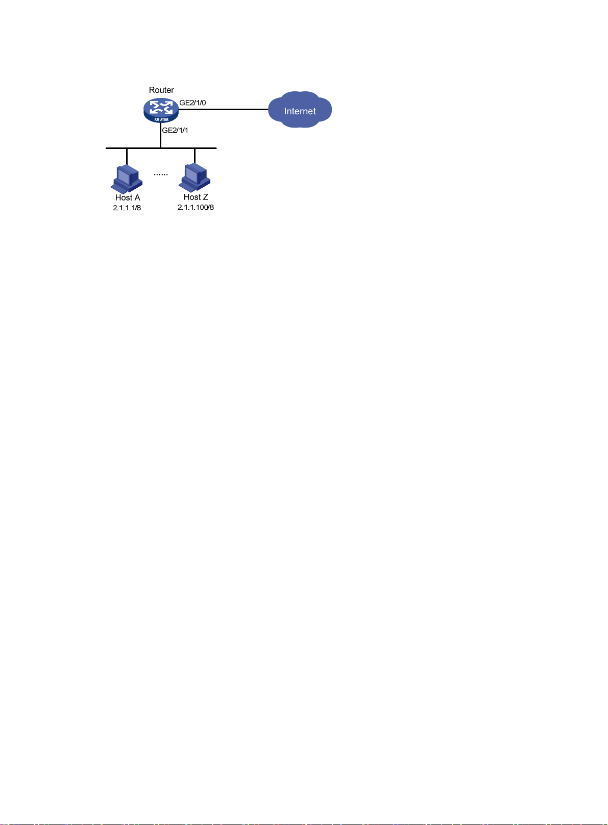
Figure 12 Network diagram
Configuration procedure
# Configure per-IP-address rate limiting on GigabitEthernet 2/1/1 to limit the rate of each host on the
network segment 2.1.1.1 through 2.1.1.100, and allow all IP addresses in the network segment to share the
remaining bandwidth.
<Router> system-view
[Router] qos carl 1 source-ip-address range 2.1.1.1 to 2.1.1.100 per-address
shared-bandwidth
[Router] interface gigabitethernet 2/1/1
[Router-GigabitEthernet2/1/1] qos car inbound carl 1 cir 500 cbs 1875 ebs 0 green pass
red discard
[Router-GigabitEthernet2/1/1] quit
Page 48

Configuring congestion management
In this chapter, "MSR1000" refers to MSR1002-4. "MSR2000" refers to MSR2003, MSR2004-24,
MSR2004-48. "MSR3000" collectively refers to MSR3012, MSR3024, MSR3044, MSR3064.
"MSR4000" collectively refers to MSR4060 and MSR4080.
Overview
Congestion occurs on a link or node when traffic size exceeds the processing capability of the link or
node. It is typical of a statistical multiplexing network and can be caused by link failures, insufficient
resources, and various other causes. Figure 13 shows common congestion scenarios.
Figure 13 Traffic congestion causes
Congestion produces the following negative results:
• Increased delay and jitter during packet transmission.
• Decreased network throughput and resource use efficiency.
• Network resource (memory, in particular) exhaustion and system breakdown.
Congestion is unavoidable in switched networks or multiuser application environments. To improve the
service performance of your network, implement congestion management policies.
For example, congestion management defines a resource dispatching policy to prioritize packets for
forwarding when congestion occurs.
Congestion management involves queue creating, traffic classification, packet enqueuing, and queue
scheduling.
Queuing is a common congestion management technique. It classifies traffic into queues and picks out
packets from each queue by using an algorithm. Various queuing algorithms are available, and each
addresses a particular network traffic problem. Your choice of algorithm significantly affects bandwidth
assignment, delay, and jitter.
This section describes several common queue-scheduling mechanisms.
46
Page 49

FIFO
Figure 14 FIFO queuing
As shown in Figure 14, the first in first out (FIFO) uses a single queue and does not classify traffic or
schedule queues. FIFO delivers packets depending on their arrival order: the packet that arrives earlier
is scheduled first. The only concern of FIFO is queue length, which affects delay and packet loss rate. On
a device, resources are assigned to packets depending on their arrival order and load status of the
device. The best-effort service model uses FIFO queuing.
WFQ
FIFO does not address congestion problems. If only one FIFO output/input queue exists on a port, you
cannot ensure timely delivery of mission-critical or delay-sensitive traffic or smooth traffic jitter. If
malicious traffic occupies bandwidth aggressively, the problems increase. To control congestion and
prioritize forwarding of critical traffic, use other queue scheduling mechanisms, where multiple queues
can be configured. Within each queue, FIFO is still used.
Figure 15 Weighted fair queuing (WFQ)
FQ is designed to equally allocate network resources to reduce the delay and jitter of each traffic flow as
much as possible. FQ follows these principles:
• Different queues have fair dispatching opportunities for delay balancing among flows.
47
Page 50

• Short packets and long packets are equally scheduled. If long packets and short packets exist in
queues, statistically the short packets are scheduled preferentially to reduce the jitter between
packets.
WFQ considers weights when determining the queue scheduling order. Statistically, WFQ gives
high-priority traffic more scheduling opportunities than low-priority traffic. To balance the delay of every
traffic flow, WFQ automatically classifies traffic according to the "session" information of traffic, and
attempts to provide as many queues as possible for traffic flows. The session information of traffic
includes protocol type, TCP or UDP source/destination port numbers, source/destination IP addresses, IP
precedence bits in the ToS field. When dequeuing packets, WFQ assigns the outgoing interface
bandwidth to each traffic flow by precedence. The higher precedence value a traffic flow has, the more
bandwidth it gets.
For example, five flows exist in the current interface with precedence 0, 1, 2, 3, and 4, respectively. The
total bandwidth quota is the sum of all the (precedence value + 1)s, 1 + 2 + 3 + 4 + 5 = 15.
The bandwidth percentage assigned to each flow is (precedence value of the flow + 1)/total bandwidth
quota. The bandwidth percentages for flows are 1/15, 2/15, 3/15, 4/15, and 5/15, respectively.
Because WFQ can balance the delay and jitter of each flow when congestion occurs, it is suitable for
handling special situations. For example, WFQ is used in the assured forwarding (AF) services of the
RSVP, and WFQ is used to schedule buffered packets in GTS.
CBQ
Figure 16 CBQ
Class-based queuing (CBQ) extends WFQ by supporting user-defined classes. When network
congestion occurs, CBQ uses user-defined traffic match criteria to enqueue packets. Before packets are
enqueued, congestion avoidance actions, such as tail drop or WRED and bandwidth restriction check,
are performed. When being dequeued, packets are scheduled by WFQ.
CBQ provides the following queues:
48
Page 51

yp
• Emergency queue—Enqueues emergent packets. The emergency queue is a FIFO queue without
bandwidth restriction.
• Low Latency Queuing (LLQ)—An EF queue. Because packets are fairly treated in CBQ,
delay-sensitive flows like video and voice packets might not be transmitted timely. To solve this
problem, LLQ combines PQ and CBQ to preferentially transmit delay-sensitive flows like voice
packets. When defining traffic classes for LLQ, you can configure a class of packets to be
preferentially transmitted. The packets of all priority classes are assigned to the same priority queue.
Bandwidth restriction on each class of packets is checked before the packets are enqueued. During
the dequeuing operation, packets in the priority queue are transmitted first. To reduce the delay of
the other queues except the priority queue, LLQ assigns the maximum available bandwidth to each
priority class. The bandwidth value polices traffic during congestion. When no congestion is
present, a priority class can use more than the bandwidth assigned to it. During congestion, the
packets of each priority class exceeding the assigned bandwidth are discarded.
• Bandwidth queuing (BQ)—An AF queue. The BQ provides guaranteed bandwidth for AF traffic,
and schedules the AF classes proportionally. The system supports up to 64 AF queues.
• Default queue—A WFQ queue. The default queue transmits the BE traffic by using the remaining
interface bandwidth.
The system matches packets with classification rules in the following order:
• Match packets with priority classes and then the other classes.
• Match packets with priority classes in the configuration order.
• Match packets with other classes in the configuration order.
• Match packets with classification rules in a class in the configuration order.
Congestion management technique comparison
Congestion management techniques offer different QoS capabilities to meet different application
requirements, as explained in Table 3.
Table 3 Congestion management technique comparison
T
e Number of queues Advantages Disadvantages
• All packets are treated equally.
The available bandwidth, delay
and drop probability are
determined by the arrival order of
packets.
• No restriction on traffic from
FIFO
• No need to configure, easy
1
to use.
• Easy to operate, low delay.
connectionless protocols
(protocols without any flow control
mechanism, UDP, for example),
resulting in bandwidth loss for
traffic of connection-oriented
protocols (TCP, for example).
• No delay guarantee for
time-sensitive real-time
applications, such as VoIP.
49
Page 52

Type Number of queues Advantages Disadvantages
• Easy to configure.
• Bandwidth guarantee for
packets from cooperative
(interactive) sources (such as
TCP packets).
• Reduces jitter.
• Reduces the delay for
WFQ Configurable
interactive applications with
a small amount of data.
The processing speed is slower than
FIFO.
• Bandwidth assignment
based on traffic priority.
• Automatic bandwidth
reassignment to increase
bandwidth for each class
when the number of traffic
classes decreases.
• Flexible traffic classification
based on rules and
differentiated queue
scheduling mechanisms for
EF, AF and BE services.
• Highly precise bandwidth
guarantee and queue
scheduling on the basis of
AF service weights for
various AF services.
• Absolute preferential queue
scheduling for the EF service
to meet the delay
requirement of real-time
data.
The system overheads are large.
CBQ
Configurable (0 to
64)
• Overcomes the PQ
disadvantage where some
low-priority queues are not
serviced by restricting the
high-priority traffic.
• WFQ scheduling for
best-effort traffic (the default
class).
Configuring the FIFO queue size
FIFO is the default queue scheduling mechanism for an interface, and the FIFO queue size is
configurable. Queue length can affect delay and packet loss ratio.
You must enable the rate limit function for the queuing function to take effect on a subinterface.
To configure the FIFO queue size:
50
Page 53

p
Step Command
1. Enter system view.
w:
pe
2. Enter interface or PVC
view.
3. Configure the FIFO queue
size.
• Enter interface vie
interface interface-ty
interface-number
• Enter PVC view:
a. interface atm
interface-number
b. pvc vpi/vci
qos fifo queue-length
queue-length
Displaying and maintaining FIFO
Ex y view
ecute the display command in an
Task Command
.
Remarks
N/A system-view
N/A
The default FIFO queue size
If the burst traffic is too heavy, increase
the queue length to make queue
scheduling more accurate.
is 75.
Conf
Display the FIFO configuration and display qos queue fifo interface [ interface-type interface-number
[ pvc { pvc-name | vpi/vci } ] ] statistics for an interface or PVC.
iguring WFQ
You must enable the
• Tunnel interfaces.
• Subinterfaces.
• HDLC link bundle interfaces.
• VT/dialer interfaces configured with PPPoE, PPPoA, PPPoEoA, PPPoFR, or MPoFR. (Frame relay
traffic shaping is not enabled on an interface configured with PPPoFR or MPoFR).
On an interface or PV
onfigure WFQ-relatc
command can modify the WFQ-related parameters.
To configure WFQ:
Ste
Command
1. Enter system view.
2. Enter interface or PVC view.
rate limit function for the queuing function to take effect on these interfaces:
C that is not enabled with WFQ, the qos wfq command can enable WFQ and
ed parameters. If WFQ has been enabled for the interface or PVC, the qos wfq
Remarks
system-view N/A
• Enter interface view:
interface interface
• Enter PVC view:
a. interface atm interface-number
b. pvc vpi/vci
-type interface-number
N/A
51
Page 54

Displ
Step Command
qos wfq [ dscp | precedence ] [ queue-length
3. Configure WFQ.
max-q
ueue-length | queue-number
total-q
ueue-number ] *
aying and maintaining WFQ
Execute display commands in any view.
Task
Display the WFQ configuration and statistics
for an interface or PVC.
Command
display qos queue wfq interface [ interfac
interface-number [ pvc { pvc-name | vpi/vci
Remarks
By default, WFQ is not
configured.
Configuring CBQ
Predefined classes, traffic behaviors, and policies
The system predefines the following classes, traffic behaviors, and policies:
e-type
} ] ]
Predefine
Predefine
Predefine
d classes
The system predefines some classes and defines general rules for the classes. You can u
predefined classes wh
• default-class—Matches the default traffic.
• ef, af1, af2, af3, af4—Matches IP DSCP value ef, af1, af2, af3, af4, respectively.
• ip-prec0, ip-prec1, …ip-prec7—Matches IP precedence value 0, 1, …7, respectively.
• mpls-exp0, mpls-exp1, …mpls-exp7—Matches MPLS EXP value 0, 1, …7, respectively.
en defining a policy:
se these
d traffic behaviors
The system predefines some tra
• ef—Assigns a class of packets to the EF queue and assigns 20% of the available interface or PVC
bandwidth to the class of packets.
• af—Assigns a
bandwidth to the class of packets.
• be—Defines no features.
• be-flow-based—Assigns a class of p
WRED. By default, 256 WFQ queues exist, and WRED is an IP precedenc
class of packets to the AF queue and assigns 20% of the available interface or PVC
ffic behaviors and defines QoS features for the behaviors.
ackets to a WFQ queue and specifies the drop policy as
e-based drop policy.
d QoS policy
The system predefines a QoS policy, specifies a predefined class for the policy and a
predefined behavior with the class. The policy is named default, with the default CBQ action.
ssociates a
The policy default is defined as follows:
• Associates the predefined class ef with the predefined traffic behavior ef.
• Associates predefined classes af1 through af4 with the predefined traffic behavior af.
52
Page 55

p
• Associates the predefined class default-class with the predefined traffic behavior be.
Defining a class
Defin
Configur
tS ep Command
1. Enter system view.
2. Create a class and
enter class view.
3. Configure match
criteria.
system-view N/A
traffic classifie
classifier-name [ operator
{ and | or } ]
if-match [ not ] match-criteria
r
Remarks
By default, no class is created.
By default, no match criterion is configu
For more info
criteria, see ACL and QoS Command
Reference.
rmation about configuring match
red.
ing a traffic behavior
To define a traffic behavior, create the traffic behavi
behavior view.
e AF and the minimum guaranteed bandwidth
When you configure AF and the minimum guaranteed bandwidth, follow these guidelines:
• You can apply this traffic behavior only to the outgoing traffic of an interface.
• You cannot configure the queue ef command together with the queue af command in the sam
traffic behavior.
or first and then configure QoS attributes in traffic
e
• To configure que
ue af for multiple classes of a policy, you must configure them in one of the
following units:
Bandwidth.
{
{ Percentage of the available bandwidth.
{ Percentage of the remaining bandwidth.
• To configure both the queue ef command and the queue af command in a policy, you must
configure them in the same unit (either bandwidth or per
percentage of the remaining bandwidth, you can config
T igure AF and the minimum bandwidth:
o conf guaranteed
S e
t
Command
1. Enter system view.
2. Create a traffic behavio
enter traffic behavior v
3. Configure AF and the
minimum guaranteed
bandwidth.
r and
iew.
system-view N/A
queue af bandwidth { ba
pct percentage | remaining-pct
remain
Configuring EF and the maximum bandwidth
centage). When you configure AF in
ure EF in an absolute value or percentage.
Remarks
By default, no behavior is created. traffic behavior behavior-name
ndwidth |
By default, AF is not configured.
ing-percentage }
When you configure EF and the maximum bandwidth, follow these guidelines:
53
Page 56

• You cannot configure the queue ef command together with the any of the commands queue af and
queue-length for a traffic behavior.
• The default class c
• To configure que
following units:
{ Bandwidth.
{ Percentage of the available bandwidth.
• To configure both the queue ef command and the queue af command in a policy, you must
configure them in the same unit (either band
percentage of the remaining bandwidth, you can configure EF in an absolute value or percentage.
T igure EF and the maximum
o conf bandwidth:
Step Command
1. Enter system view.
2. Create a traffic behavi
enter traffic behavior vi
3. Configure EF and the
maxi
Configuring WFQ
annot be associated with a traffic behavior including EF.
ue ef for multiple classes of a policy, you must configure them in one of the
mum bandwidth.
or and
ew.
width or percentage). When you configure AF in
Remarks
system-view N/A
queue ef bandwidth
[ cbs burst ] | pct percentage
[ cbs-ratio ratio] }
{ bandwidth
By default, EF is not configured.
.traffic behavior behavior-name By default, no behavior is created
Step Command
1. Enter system view.
2. Create a traffic be
3. Configure WFQ.
You can associate the traffic behavior that contains a WFQ action only with the default class.
Configurin maximum queue size g the
Step Command
1. Enter system view.
2. Create a traffic behavior and
3. Set the maximum queue size.
havior and
enter traffic behav
enter traffic behavior view.
ior view.
Remarks
system-view N/A
traffic behavior behavior-name By default, no behavior is created.
queue wfq [ queue-number
total-queue-number ]
By default, WFQ is not config
ured.
Remarks
system-view N/A
traffic behavior behavior-name By default, no behavior is created.
the
queue-length queue-length
By default, tail drop is used and
queue size is 64.
If the burst traffic is too heavy,
increase the queue length to make
queue scheduling more accurate.
Configure the queue af command or the queue wfq command before you configure the queue-length
command. The undo queue af or undo queue wfq command also cancels the queue-length command.
54
Page 57

p
p
Enabling WR
When you enable WRED, follow these guidelines:
• Before enablin
• wred command and the queue-len command are mutually xclusive.
The
• en WRED is disabled, other WR nfigurations ar
To enable WRED:
Ste
1. Enter system view.
2. Create a traffic behavior
3. Enable WRED.
Configur
ing the exponent for WRED to calculate the average queue size
B onfiguring the WRED expone the queue af or command has been
efore c
c ed and the wred command ha nable WRED.
onfigur
To configure the exponent for WR
ED
g WRED, configure the queue af or queue wfq command.
Wh
and enter traffic behavior
view.
gth
ED co
Command
traffic behavior
behavior-name
wred [ dscp |
ip-precedence ]
nt, make sure
s been used to e
ED to calculate the average queu
e deleted.
Remarks
N/Asystem-view
By default, no traffic behavior is created.
By default, WRED is not enabled.
e
queue wfq
e size:
Ste
1. Enter system view.
2. Create
3. Configure the exponent for WRED
Configur r a DSCP value in WRED
ing the lower limit, upper limit, and drop probability denominator fo
To perform this configuration, make sure DSCP-based WRED has been enabled with the wred dscp
command.
Disabling WRED also removes the wred dscp command configuration.
emovi
R ng the queue af or queu mand configuration ves the WRED-related
ameter
par s.
To configure the lower limit, upper limit
Step Command
1. Enter system view.
2. Create a traffic behavior and
a traffic behavior and
enter traffic behavior view.
to calculate the average queue
size.
enter traffic behavior view.
Command
system-view N/A
traffic behavior behavior-name
wred weighting-constant
exponent
e wfq com also remo
, and drop probability denominator for a DSCP value in WRED:
system-view N/A
traffic behavior behavior-name
Remarks
By default, no traffic behavior is
created.
The default setting is 9.
Remarks
By default, no traffic behavior is
created.
55
Page 58

p
in WRED
Step Command
3. Configure the lower limit,
upper limit, and drop
probability denominato
DSCP value in WRED.
r for a
wred dscp dscp-value low-limit
low-limit high-limit high-limit
[ discard-probability discard-prob ]
Remarks
By default, low-limit is 10,
high-limit is 30, and discard-prob
is 10.
Repeat this co
more DSCP val
mmand to configure
ues.
ing the lowerConfigur limit, upper limit, and drop probability denominator for an IP precedence value
o pe rm T rfo
ip-pr dence command.
Disabling WRED also re wred ip-prece figurat n.
Removing the queue af or que
parameters.
To configure the lower limit, up
in WRED:
Ste
1. Enter system view.
this configuration, make sure IP pr edence-based WRED has been enabled with the wred
ece
moves the dence command con io
ue wfq command configur n ed
per limit, and drop probability denom e value
Command
system-view N/A
ec
atio also removes the WRED-relat
inator for an IP precedenc
Remarks
2. Create a traffic behavior and
enter traffic behavior view.
3. Configure the lower limit,
upper limit, and drop
robability denominator for
p
an IP precedence v
WRED.
alue in
Defining a QoS policy
Step Command
1. Enter system view.
2. Create a policy and enter
policy view.
3. Associate a traffic
behavior with a class in the
policy.
plying tAp
he QoS policy
traffic behavior behavior-name
wred ip-precedence precedence
low-limit l
high-limit
discard-pro
system-view N/A
qos policy policy-name By default, no policy is created.
classifier classifier-name
beh
avior behavior-name
ow-limit high-limit
[ discard-probability
b ]
Remarks
By default, a class is not associated with a
behavior.
By default, no traffic behavior is
created.
By default, low-limit is 10,
high-limit is 30, and discard-prob
is
Repeat this command to configure
more IP precedence values.
10.
Use the qos apply policy command to apply a policy to a physical interface or PVC. You can apply
policy to multiple p
hysical interfaces or PVCs.
56
a
Page 59

p
Configura strictions and guidelines
tion re
• You can apply a Q onfigured w ical in
remark, car, queue af
• An inbound QoS policy ctions: queue ef, queue af, or queue wfq.
• You must enable the rat uing function to t
oS policy c ith QoS actions to phys terfaces, for example
, queue ef, and queue wfq.
cannot contain these queuing a
e limit function for the que ake effect on subinterfaces.
Configuration procedure
To apply a policy to an interface or PV
Command
Ste
1. Enter system view.
2. Enter interface or PVC view.
3. Apply a policy to the interface
or PVC.
C:
Remarks
system-view N/A
• Enter interface view:
interface interface-type
interface-number
• Enter PVC view:
a. interface atm
interface-number
b. pvc vpi/vci
qos apply policy policy-name By default, no QoS policy is
{ inbound | outbound }
Settings in interface view
effect on the current interface.
Settings in PVC view take effect
on the current PVC.
applied to an interface or PVC.
take
Configuring the maximum available interface bandwidth
The maximum available interface bandwidth refers to the maximum interfa
bandwidth check when CBQ enqueues packets. It is not the actual bandwidth of the physical interface.
If no maximum availa
CBQ calculation:
• The actual baud rate or rate if the interface is a physi
0 kbps if the interface is a virtual interface, for example•
Configura uidelines
tion g
• HP recommends th onfigure the
the actual available width of the physical interface or logic l link.
• On subinterfaces, you m
calculation.
Config
uration procedure
To configure the maximum interface available bandwidth:
Step Command
1. Enter system view.
ble bandwidth is configured for an interface, the following bandwidth is used for
cal one.
, HDLC link bundle interface.
at you c maximum available interface bandwidth to be smaller than
band a
ust configure the bandwidth command to p Q
rovide base bandwidth for CB
Remarks
system-view N/A
ce bandwidth used for
2. Enter interface view.
3. Configure the maximum
available bandwidth of
the interface.
interface interface-type interface-number
bandwidth bandwidth-value
57
N/A
For more information about this
command, see In
Command Reference.
terface
Page 60

p
Settin
g the maximum reserved bandwidth as a percentage of
available bandwidth
he maximum reserved bandwidth is set on a per-interface basis and decides the maximum bandwidth
T
a ble for the QoS queues on e. It is typically set n han 80% of available
ssigna an interfac o greater t
bandwidth, considering idth for contr frame
Use the default maximum r st situations. When tuning the setting, make
sure the Layer 2 frame header plu the maximum available bandwidth of the
interface.
To configure the maximum reserved bandwidth on an in
Ste
Command
1. Enter system view.
2. Enter interface view.
3. Set the maximum reserved
b
andwidth as a percentage of
a
vailable bandwidth.
the bandw ol traffic and Layer 2 headers.
eserved bandwidth setting in mo
s the data traffic is under
terface:
Remarks
system-view N/A
• Enter interface view:
interf
ace interface-type
interface-number
• Enter PVC view
a. interface a
interface-
pvc vpi/vci
b.
qos reserved-b
percent
:
tm
number
andwidth pct
N/A
The default setting is 80.
Displaying and maintaining CBQ
E commands in any
xecute display view.
Task Command
Displa y class configuration. ed } [ classifier-name ]display traffic classifier { system-defined | user-defin
Display traffic behavior
configuration.
Display QoS policy
configuration.
Display information about QoS
policies applied to an interface or
PVC
(MSR1000/MSR2000/MSR300
0).
Display information about QoS
policies applied
PVC (MSR4000
Display information about CBQ display qos queue cbq interface [ interface-type interfac
on an interface or PVC.
to an interface or
).
display traffic behavior { system-defined | user-defined } [ behavior-name ]
display qos policy { system-defined | user-defined } [ policy-name
[ classifier classifier-name ] ]
display qos policy interface
{ pvc-name | vpi/vci } ] ] [ inbound | outbound ]
display qos policy interface [ interface-type interface-number [ pvc
{ pvc-name | vpi/vci } ] ] [ slot slot-number ] [ inbound | outbound ]
{ pvc-name | vpi/vci } ] ]
[ interface-type interface-number [ pvc
e-number [ pvc
58
Page 61

C
BQ configuration example
Network re
As shown in Figure 1
• Traffic from Router C is classified into three cla
• Perform EF for traffic with a DSCP value of EF and set the maximum bandwidth
Before performing the configuration, make sure:
• The route from Router C to Router D through Router A and R
• The DSCP fields have been set for the traffic before the traff
Figure 17 Network diagram
quirements
7, configure a QoS policy to meet the following requirements:
sses based on DSCP values. Perform AF for traffic with
DSCP values of AF11 and AF21, and set a minimum guaranteed bandwidth perce
the traffic.
traffic to 30%.
outer B is reachable.
ic enters Router A.
Router C
Router A
GE2/1/0
1.1.1.1/24
AF11
AF21
EF
Router D
EthernetEthernet
GE2/1/0
1.1.1.2/24
Router B
ntage of 5% for
percentage for the
Configur
ing Router A
# Define three classes to match the IP packets w
<RouterA> system-view
[RouterA] traffic classifier af11_clas
[RouterA-classifier-af11_class] if-matc
[RouterA-classifier-af11_class] quit
[RouterA]traffic classifier af21_cla
[RouterA-classifier-af21_class] if-match dscp af21
[RouterA-classifier-af21_
[RouterA] traffic classifier ef_class
[RouterA-classifier-ef_class] if-match dscp ef
[RouterA-classifier-ef_class] quit
class] quit
# Define two traffic behaviors, and enable AF
5% in each traffic behavior.
[RouterA] traffic behavior af11_beha
[RouterA-behavior-af11_behav] queue af bandwidth pct 5
[RouterA-behavior-af11_behav] quit
[RouterA] traffic behavior af21_behav
[RouterA-behavior-af21_behav] queue af bandwidth pct 5
ith the DSCP values AF11, AF21, and EF, respectively.
s
h dscp af11
ss
and set a minimum guaranteed bandwidth percentage of
v
59
Page 62

[RouterA-behavior-af21_behav] quit
Conf
# Define a traffic behavior, and enable EF and set a maximum bandwidth percentage of 30% (both
bandwidth and delay are guaranteed f
[RouterA] traffic behavior ef_behav
[RouterA-behavior-ef_behav] queue ef bandwidth pct 30
[RouterA-behavior-ef_behav] quit
# Define a QoS policy and associat
[RouterA] qos policy dscp
[RouterA-qospolicy-dscp] classifier af11_cl
[RouterA-qospolicy-dscp] classifier af21_class behavior af21_beha
[RouterA-qospolicy-dscp] classifier ef_class behavior ef_behav
[RouterA-qospolicy-dscp] quit
or EF traffic) in the traffic behavior.
e the configured traffic behaviors with classes in the QoS policy.
ass behavior af11_behav
v
# Apply the QoS policy to the outgoing traffic of GigabitEthernet 2/1/0.
[RouterA] interface gigabitethernet 2/1/0
[RouterA-GigabitEthernet2/1/0] ip address 1.1.1.1 255.255.255.0
[RouterA-GigabitEthernet2/1/0] qos apply policy dscp outbound
The configuration enables EF traffic to be forwarded preferentially when congestion occurs.
iguring packet information pre-extraction
If a tunnel interface has processed the incoming IP packets, for example, if the tunnel interface has used
GRE to encapsulate packets, the GRE
result, the QoS module cannot obtain the I
To process the original IP packets with QoS on
ket information pre-extraction on the logical interface.
pac
Configuration procedure
To configure packet information pr
Step Command Remarks
1. Enter system view.
2. Enter tunnel interface view.
3. Enable packet information
pre-extraction on the tunnel
interface.
Configuration example
-encapsulated packets enter the QoS module for processing. As a
P information of the original packets.
the physical interface for a tunnel interface, configure
e-extraction:
system-view N/A
interface tunnel interface-number N/A
By default, packet information
qos pre-classify
pre-extraction is disabled on a
tunnel interface.
Network
requirements
Enable packet information pre-extra
Configuration procedure
# Enable packet information pre-extraction on tunnel interface Tunnel 0.
ction on a tunnel interface.
60 61
Page 63

<Sysname> system-view
[Sysname] interface tunnel 0
[Sysname-Tunnel0] qos pre-classify
Page 64

Configuring congestion avoidance
Overview
Avoiding congestion before it occurs is a proactive approach to improving network perform
flow control mechanism, congestion avoidance:
• Actively monitors network resources (such as queues and memory buffers).
• Drops packets when congestion is expected to occur or deteriorate.
When dropping packets from a source end, congestion avoidance cooperates wi
mechanism at the source end to regulate the network traffic size. The combination of
drop policy and the source-end flow control mechanism helps maximize throughp
efficiency and minimize packet loss and delay.
Tail drop
Congestion management techniques drop all packets that are arriving at a full queue
mechanism results in global TCP synchronization. If packets from multiple TCP connectio
these TCP connections go into the state of congestion avoidance and slow start to re
traffic peak occurs later. Consequently, the network traffic jitters all the time.
RED and WRED
ou can use Random Early Detection (RED) or Weighted Random Early Detection (WRED) to avoid
Y
global TCP synchronization.
ance. As a
th the flow control
the local packet
ut and network use
. This tail drop
ns are dropped,
duce traffic, but
Both RED and WRED avoid global TCP synchronization by randomly dropping packets. When the
sending rates of some TCP sessions slow dow
remain at high sending rates. Link bandwidth is e
rates always exist.
The RED or WRED algorithm sets an upper threshold
the packets in a queue as follows:
• When the queue size is shorter than the lower threshold, no packet is dropped.
• When the queue size reaches the upper threshold, all subsequent packets are dropped.
• When the queue size i
are dropped at random. The drop probability in a queue inc
the maximum drop probability.
If the current queue size is
policy, burst traffic is not f
with the upper threshold and lower threshold to determine the drop probability.
Th verage queue size reflects the queue size change trend but is not sensitive to burst queue siz
e a
changes, and burst traffic can be fairly treated.
s between the lower threshold and the upper threshold, the received packets
compared with the upper threshold and lower threshold to determine the drop
airly treated. To solve this problem, WRED compares the average queue size
n after their packets are dropped, other TCP sessions
fficiently used, because TCP sessions at high sending
and lower threshold for each queue, and processes
reases along with the queue size under
e
62
Page 65

With WFQ queuing used, you can set the exponent for average queue size calculation, upper threshold,
lower threshold, and drop probability for packets with different precedence values respectively to
provide differentiated drop policies.
With FIFO queuing used, you can set the exponent for average queue size calculation, upper threshold,
lower threshold, and drop probab
ility for each queue to provide differentiated drop policies for different
classes of packets.
Rel
ationship between WRED and queuing mechanisms
Figure 18 Relationship between WRED and queuing mechanisms
WRED drop
Packets to be sent
through this interface
……
Classify
Packets
dropped
Through combining W
own queue after cla
RED with WF ealiz has its
ssification, a flo a smaller queue size has a lo t drop probability,
when a flow with a larger queu
flow with a smaller queue size ar protected.
Queue 1 weight 1
Queue 2 weight 2
……
Qu
eue N-1 weight N-1
Queue N weight N
Q, the flow-based WRED can be r
w with
e size has a higher packet drop probability. In this way, the benefits of the
e
Schedule
Packets sent
Interface
Sending queue
ed. Because each flow
wer packe
WRED configuration approaches
You can configure WRED by using
• Interface configuration
• WRED table configuration—Configure a WRED table in system view n apply the WRED
table to an interface.
The router supports only the interf
WRED parame
Determine the following param
• Upper threshold and lower threshold—When the average queue size is sm
threshold, packets are not dropped. When the average queue size is between the lower threshold
and the upper threshold, the packets are dro
—Conf interfac
ters
one of the following approaches:
igure WRED parameters on an e and enable WRED.
ace configuration approach.
eters before configuring WRED:
pped at random. The longer the queue, the higher the
63
and the
aller than the lower
Page 66

drop probability. When the average queue size exceeds the upper threshold, subsequent packets
are dropped.
• Drop precedence—A parameter used for packet drop. The value 0 corresponds to green packets,
the value 1 corre
are dropped preferen
sponds to yellow packets, and the value 2 corresponds to red packets. Red packets
tially.
Conf
Confi
• Exponent for average queue si
average queue size is to real-time queue size c
queue size is average queue size =
–n
x 2 ), where n is the exponent.
ze calculation—The greater the exponent, the less sensitive the
hanges. The formula for calculating the average
( previous average queue size x (1 – 2
–n
) ) + (current queue size
• Denominator for drop probability calculation—The greater the denominator, the smaller the
calculated drop probability.
iguring WRED on an interface
guration procedure
To configure WRED on an interface:
Step Command
1. Enter system view.
system-view N/A
• Enter int
interf
ace
2. Enter interface or
PVC view.
interface
• Enter PVC view:
a. interface atm interface-number
b. pvc vpi/vci
erface view:
interface-type
-number
Remarks
N/A
3. Enable WRED.
4. (Optional.) Set the WRED
exponent for average queue
size calculation.
5. (Optional.) Set the
drop-related parameters for a
precedence value.
Configuration example
Network requirements
Configure WRED as follows:
• Enable IP precedence-based WRED on interface GigabitEthernet 2/1/0.
• Set the following parameters for packets with IP precedence 3: lower threshold 20, upper threshold
40, and drop probability denominator 15.
qos wred [ dscp | ip-precedence ]
enable
qos wred weighting-constant exponent
qos wred { ip-precedence
ip-precedence | dscp dscp-value }
low-limit low-limit high-limit high-limit
discard-probability discard-prob
By default, tail drop is
adopted.
The default setting is 9.
By default, low-limit is 10,
high-limit is 30, and
discard-prob is 10.
Repeat this command to
configure more precedence
values.
64 65
Page 67

• Set the exponent for average queue size calculatio
Configuration procedure
# Enter system view.
<Sysname> system-view
# Enter interface view.
[Sysname] interface gigabitethernet 2/1/0
# Enable IP precedence-based WRED.
[Sysname-GigabitEthernet2/1/0] qos wred
# Set the following parameters for packets with IP precedence value 3: lower threshold 20, upper
threshold 40, and drop prob
[Sysname-GigabitEthernet2/1/0] qos wred ip-precedence 3 low-limit 20 high-limit 40
discard-probability 15
n to 6.
ip-precedence enable
ability denominator 15.
# Set the exponent for a queue size ca
[Sysname-GigabitEthernet2 /0] qos wred weighting-constant 6
verage lculation to 6.
/1
Displaying and maintaining WRED
Execute display commands in any view.
Task
Display WRED configuration a
an interface or PVC.
nd statistics for display qos wred interface [
Command
| vpi/vci }
interface-type interface-number
] ] [ pvc { pvc-name
Page 68

Configuring traffic filtering
You can filter in or filter out traffic of a class by associating the class with a traffic filtering action. For
example, you can filter packets sourced from a specific IP address according to network status.
Configuration procedure
To configure traffic filtering:
Step Command
1. Enter system view.
2. Create a traffic class and
enter traffic class view.
3. Configure match criteria.
4. Return to system view.
5. Create a traffic behavior
and enter traffic behavior
view.
6. Configure the traffic
filtering action.
7. Return to system view.
8. Create a QoS policy and
enter QoS policy view.
9. Associate the traffic class
with the traffic behavior in
the QoS policy.
system-view N/A
traffic classifier classifier-name [ operator By default, no traffic class is
{ and | or } ] configured.
if-match [ not ] match-criteria
quit N/A
traffic behavior be
filter { deny | pe
quit N/A
qos policy policy-n
classifier classifier-name behavior
behavior-name
havior-name
rmit }
ame
Remarks
By default, no match criterion
is configured.
By default, no traffic behavior
is configured.
By default, no traffic filtering
action is configured.
By default, no QoS policy is
configured.
By default, a traffic class is not
associated with a traffic
behavior.
10. Return to system view.
11. Apply the QoS policy.
12. (Optional.) Display the
traffic filtering
configuration.
quit N/A
• Applying the QoS policy to an
interface or PVC destinations as nee
• Applying the Q
plane
display qos policy user-defined
[ policy-name ]
oS policy to the control
66 67
Choose one of the application
By default, no QoS policy is
ap
plied.
Available in any view.
ded.
Page 69

Configuration example
Network requirements
As shown in Figure 19, configure traffic filtering on GigabitEthernet 2/1/0 to deny the incoming packets
with a source port number other than 21.
Figure 19 Network diagram
Configuration procedure
# Create advanced ACL 3000,
.
21
<Router> system-view
[Router] acl number
[Router-acl-adv-3000] rul
[Router-acl-adv-3000] quit
3000
# Create a traffic class named classifier_1, and use ACL 3000 as the match c lass.
[Router] traffic classifier classifier_1
[Router-classifier-classifier_1] if-match acl 3000
[Router-classifier-classi r_1] quit
# Create a traffic behavior named behavior_1, and configure the traffic filterin s.
[Router] traffic behavior behavior_1
[Router-behavior-behavi fil
[Router-behavior-behavio
# Create a QoS policy nam
behavior_1
[Router] qos policy policy
[Router-qospolicy-policy] classifier classifier_1 behavior behavior_1
[Router-qospolicy-po
# Apply the QoS policy bitEthernet 2/1/0.
[Router] interface giga
in the QoS policy.
licy] quit
named policy to the incoming traffic of Giga
and configure a rule to match packets whose source port number is not
permit tcp source-port neq 21
e 0
riterion in the traffic c
fie
g action to drop packet
or_1] ter deny
r_1] quit
ed class classifie avior
policy, and associate traffic r_1 with traffic beh
bitethernet 2/1/0
et
2/1/0] qos apply policy policy inbound [Router-GigabitEthern
Page 70

Configuring priority marking
Priori ty m arki ng s ets the priori ty fi f packets to modify the priori le,
elds or flag bits o ty of packets. For examp
you can use priority marking to set IP precedence or DSCP for a traffic class o ntrol the
forwarding of these packets
.
To configure priority marking, you a h
et the pri ields or flag bits of the traffic class o
Priority marking can be used tog h infor
priority mapping."
Co proce
nfiguration dure
To configure priority marking:
Step Command
1. Enter system view.
2. Create a traffic class and
enter traffic class view.
3. Configure match criteria.
f IP packets to co
c n associate a traffic class with a traffic be
ority f
avior configured with the
f packets. priority marking action to s
et er with priority mapping. For more mation, see "Configuring
Remarks
system-view N/A
traffic classifier classifier-name [ operator { and
| or } ]
if-match [ not
] match-criteria
By default, no traffic class
is configured.
By default, no match
criterion is configured.
For more inform
about the
command, see
QoS
Command
Reference.
ation
if-match
ACL and
4. Return to system view.
5. Create a traffic behavior
and enter traffic behavior
view.
6. Configure a priority
marking action.
7. Return to system view.
quit N/A
traffic behavior behavior-name
By default, no traffic
behavior is configured.
• Set the DSCP value for packets:
remark dscp dscp-value
• Set the 802.1p priority for packets:
remark dot1p dot1p-value
Set the IP precedence for packets:
remark ip-precedence ip-precedence-value
• Set the local precedence for packets:
remark local-precedence
local-precedence-value
Use one of the
commands.
By default, no priority
marking action is
configured.
• Set the local QoS ID for packets:
remark qos-local-id local-id-value
quit N/A
68
Page 71

Step Command
8. Create a QoS policy and
enter QoS policy view.
9. Associate the traffic class
or in
Conf
with the traffic behavi
the QoS policy.
10. Return to system view.
11. Apply the
12. (Optional.) Display the
priority marking
configuration.
QoS policy.
iguration example
Network requirements
Remarks
qos policy policy-name
classifier classifier-name behavior
behavior-name
quit N/A
• Applying the QoS policy to an interface or
PVC
• Applying the QoS policy to the control
plane
display qos policy user-defined [ policy-name ] Available in any view.
By default, no QoS policy
is configured.
By default, a traffic class
is not associated with a
traffic behavior.
Choose one of the
application destinations
as needed.
By default, no QoS policy
is applied.
As shown in Figure 20, configure priority marking on the router to me
Traffic source Destination
Host A, B Data server High
Host A, B Mail server Medium
Host A, B File server Low
et the following requirements:
Processing priority
Figure 20 Network diagram
69
Page 72

Confi
guration procedure
# Create advanced ACL 3000, and configure
192.168.0.1.
<Router> sy
[Router] acl number 3000
[Router-acl-adv-3000] rule permit ip destination 192.168.0.1 0
[Router-acl-adv-3000] quit
stem-view
# Create advanced ACL 3001, and configure a rule to match packets with destina
192.168.0.2.
[Router] acl numbe
[Router-acl-adv-3001] rule permit ip de
[Router-acl-adv-3001] quit
r 3001
# Create advanced ACL 3002, and configure a
192.168.0.3.
[Router] acl number 3002
Router-acl-adv-3002] rule permit ip destination 192.168.0.3 0
[
[Router-acl-adv-3002] quit
# Create a traffic class named classifier_dbserver, and use ACL 3000 as the match criterion in the traffic
class.
[Router] traffic classifier classifier_dbserver
[Router-classifier-classifier_dbserver] if-match acl 3000
[Router-classifier-classifier_dbserver] quit
a rule to match packets with destination IP address
tion IP address
stination 192.168.0.2 0
rule to match packets with destination IP address
# Create a traffic class named classifier_mserver, and use ACL 3001 as the match criterion in the traffic
class.
[Router] traffic classifier classifier_mserver
[Router-classifier-classifier_mserver] if-match acl 3001
[Router-classifier-classifier_mserver] quit
# Create a traffic class named classifier_fserver, and use ACL 3002 as the match criterion in the traffic
class.
[Router] traffic classifier classifier_fserver
[Router-classifier-classifier_fserver] if-match acl 3002
[Router-classifier-classifier_fserver] quit
# Create a traffic behavior named behavior_dbserver, and configure the action of setting the local
precedence value to 4.
[Router] traffic behavior behavior_dbserver
[Router-behavior-behavior_dbserver] remark local-precedence 4
[Router-behavior-behavior_dbserver] quit
# Create a traffic behavior named behavior_mserver, and configure the action of setting the local
precedence value to 3.
[Router] traffic behavior behavior_mserver
[Router-behavior-behavior_mserver] remark local-precedence 3
[Router-behavior-behavior_mserver] quit
# Create a traffic behavior named behavior_fserver, and configure the action of setting the local
precedence value to 2.
70 71
Page 73

[Router] traffic behavior behavior_fserver
[Router-behavior-behavior_fserver] remark local-preced
[Router-behavior-behavior_fserver] quit
ence 2
# Create a QoS policy named policy_server, and associate traffic classes with traffic behaviors in the
QoS policy.
[Router] qos policy policy_server
[Router-qospolicy-policy_server] classifier c
behavior_dbserver
Router-qospolicy-policy_server] classifier classifier_mse[
behavior_mserver
[ policy-policy_server] classifier
Router-qos classifier_fserver behavior
behavior_fserver
[Router-qospolicy-policy_server] quit
# A cy named policy_server to the i 1/0.
pply the QoS poli ncoming traffic of GigabitEthernet 2/
[Router] interface gigabitethernet 2/1/0
Router-Gi cy policy_server inbound
[ gabitEthernet2/1/0] qos apply poli
[Router-GigabitEthernet2/1/0] quit
lassifier_dbserver behavior
rver behavior
Page 74

g
y
Configuring traffic redirecting
Traffic redirecting redirects packe tching the specified match criteria to a or processing.
ts ma location f
The router supports redirecting traffic to an interface.
The following matrix shows the featu
re and hardware compatibility:
Hardware Traffic redirectin
MSR1000 No
MSR2000 No
MSR3000 Yes on HMIM-24GSW interface modules
MSR4000 Yes on HMIM-24GSW interface modules
Configuration procedure
To configure traffic redirecting:
Step Command
1. Enter system view.
2. Create a traffic class and
enter traffic class view.
system-view N/A
traffic classifier classifier-name [ operator { and
| or } ]
feature compatibilit
Remarks
By default, no t
exists.
raffic class
3. Configure match criteria.
4. Return to system view.
5. Create a traffic behavi
and enter traffic behav
view.
6. Configure a traffic
redirecting action.
7. Return to system view.
8. Create a QoS policy and
enter QoS policy view.
or
ior
By default, no match
criterion is configured for
a traffic class.
if-match [ not ] match-criteria
quit N/A
traffic behavior behavior-name
redi
rect interface interface-type
interface-number configured for a traffic
quit N/A
qos policy policy-name
For more information
about the match criteria,
see the if-match
command in ACL and
QoS Command
Reference.
By default, no traffic
behavior exists.
By default, no traffic
redirecting action is
behavior.
By default, no QoS policy
exists.
72
Page 75

Conf
Netw
Step Command
9. Associate the traffic class
with the traffic behavior in
the QoS policy.
10. Return to system view.
classifier classifier-n
behavior-name
quit N/A
• Applying th
11. Apply the QoS policy.
12. (Optional.) Display traffic
redirecting configuration.
PVC
• Applying the QoS policy to the control
plane
display qos policy user-defined [ policy-name ] Available in any view.
ame behavior class-behavior
e QoS policy to an interface or
Remarks
By default, no
association is configured
for a QoS policy.
Choose one of the
application destinations
as neede
By default, a QoS policy
is not applied.
iguration example
ork requirements
As shown in Figure 21, packets from network segments 2.2.2.0/24 and 3.3.3.0/2
through GigabitEthernet 2/1/0.
d.
4 enter Router A
Configure traffic redirecting on GigabitEthernet 2/1/0 to meet the following requir
• Packets from network segment 2.2.2.0/24 are
• Packets from network segment 3.3.3.0/24 are forwarded to GigabitEth
Figure 21
Network diagram
Configuration procedure
# Create basic ACL 2000, and configure a rule to match packets from network segment 2.2.2.0/24.
<RouterA> system-view
[RouterA] acl number 2000
[RouterA-acl-basic-2000] rule permit source 2.2.2.0 0.0.0.255
[RouterA-acl-basic-2000] quit
# Create basic ACL 2001, and configure a rule to match packets from network segment 3.3.3.0/24.
[RouterA] acl number 2001
[RouterA-acl-basic-2001] rule permit source 3.3.3.0 0.0.0.255
[RouterA-acl-basic-2001] quit
ements:
forwarded to GigabitEthernet 2/1/1.
ernet 2/1/2.
# Create a traffic class named classifier_1, and use ACL 2000 as the match criterion in the traffic class.
[RouterA] traffic classifier classifier_1
[RouterA-classifier-classifier_1] if-match acl 2000
73 74
Page 76

[RouterA-classifier-classifier
_1] quit
# Create a traffic class named classif
[RouterA] traffic classifier classifier_2
[RouterA-classifier-classifier_2] if-match acl 2001
[RouterA-classifier-classifier_2] quit
# Create a traffic behavior named behavior_1, and configure the action o
GigabitEthern
[RouterA] tr
[RouterA-behavior-behavior_1] redirect interface gigabitethernet 2/1/1
[RouterA-behavior-behavior_1] quit
et 2/1/1.
affic behavior behavior_1
# Create a traffic behavior named behavior_2, and configure the action of r
ier_2, and use ACL 2001 as the match criterion in the traffic class.
f redirecting traffic to
edirecting traffic to
GigabitEthernet 2/1/2.
[RouterA] traffic behavior behavior_2
[RouterA-behavior-behavior_2] redirect interface gigabitethernet 2/1/2
[RouterA-behavior-behavior_2] quit
# Create a QoS policy named policy, associate traffic class classifier_1 with traffic behavior behavior_1,
and associate traffic class classifier_2 with traffic behavior behavior_2 in the QoS policy.
[RouterA] qos policy policy
[RouterA-qospolicy-policy] classifier classifi
[RouterA-qospolicy-policy] classifier classifier_2 behavior behavior_2
[RouterA-qospolicy-
policy] quit
er_1 behavior behavior_1
# Apply the QoS policy policy to th
[RouterA] interface gigabiteth
[RouterA-GigabitEthernet2/1/0] qos apply policy policy inbound
e incoming traffic of GigabitEthernet 2/1/0.
ernet 2/1/0
Page 77

Configuring QPPB
T th routers and Layer 3 switches.
he term "router" in this document refers to bo
Over
view
T Border Gateway Protocol (QPPB) feature enables you to
he QoS Policy Propagation Through the
c s ts, and BGP AS paths.
las ify IP packets based on BGP community lists, prefix lis
T ows:
he QPPB feature is implemented as foll
e advertising them.
The BGP route sender preclassifies routes befor•
• The BGP route receiver sets the IP precedence and local QoS ID for the routes and takes
appropriate QoS actions on the packets that match the r
QPPB minimizes the QoS policy configuration and mana
the network topology changes. It is suitable for a large-scaled complex network that clas
based on source or destination IP addresses for QoS.
QPPB applies to IBGP and EBGP. You can use i
autonomous systems.
QPPB fundamentals
QPPB works on the BGP receiver. It depends on the BGP route sender to preclassify routes.
The BGP route sender uses a routing policy to set route attributes for BGP routes before advertising them.
outes.
gement efforts on the BGP route receiver when
sifies packets
t within an autonomous system or across multiple
The BGP receiver performs the following tasks:
• Uses a routing policy to match routes based on these
• Sets IP precedence and local QoS ID for the matching
The BGP receiver performs the following tasks:
1. Compares the routes
community attributes.
2. Applies the IP precedence and local QoS ID
3. Adds the BGP routes and their associated IP precedence and local QoS ID to the routing table.
4. Applies the IP precedence and local QoS ID to the packets sour
address in the route.
5. Takes QoS actions on the packets acco
with the incoming route policy based on their BGP AS path, prefix, or
to the matching routes.
rding to the QoS priority settings.
route attributes.
routes.
ced from or destined to the IP
75
Page 78

QPPB configuration task list
Tasks at a glance
Configuring the route sender:
• (Required.) Configuring functions
• (Optional.) Creating a routing po
Configuring the route receiver:
• (Required.) Configuring basic BG functions
• (Required.) Configuring a routing policy
• (Required.) Enabling QPPB on the route receiving interface
• (Required.) Configuring a QoS policy
• (Required.) Applying the QoS policy t
basic BGP
licy
P
o an interface
Configuring the route sender
Configure the BGP route sender to set route attributes for routes b
Configuring basic BGP functions
For more information, see —IP Routing Configurati
C
reating a routing policy
onfigure a routing policy to classify routes and set route attributes for the route classes. For more
C
information, see Layer 3—IP Routing Configuration Guide
Layer 3 on Guide.
Configuring the route receiver
Configure the BGP route receiver to match the route attributes set by the router sender and set the
QPPB-related attr
Configuring basic BGP functions
For more information,
ibutes.
see Layer 3—IP Routing Configuration Guide.
efore advertising them.
.
C
onfiguring a routing policy
Configure a routing policy to match the route attributes set by the route sender, and set the IP precedence,
local QoS ID, or both for the matching routes. For more information, see Layer 3—IP Routing
Configuration Guide.
76
Page 79

p
Enabling QPPB on the route receiving interface
Step Command
1. Enter system view.
2. Enter interface view.
3. Enable QPPB
on the interface.
system-view N/A
interface interface-type
interface-number
bgp-policy { destination | source }
{ ip-prec-map | ip-qos-map } *
Configuring a QoS policy
The c use the IP precedence and local QoS ID set by the routing policy as match
lasses in the QoS policy
criter
ia.
Applying interface
the QoS policy to an
Ste
Command
1.
Enter system view.
2. Enter interface view.
system-view N/A
interface interface-type
interface-number
Remarks
N/A
By default, QPPB is disabled.
The command applies to only
incoming traffic.
Remarks
N/A
3.
QPPB c
Apply the specified policy to
the interface.
onfiguration examples
qos apply policy policy-name By defa
{ inbound | outbound }
applied.
QPPB configuration example in an IPv4 network
Network requ
irements
As sh
own in Figure 22, all routers run BGP.
Conf ing tasks:
igure QPPB so that Router B can perform the follow
•
Receive routes.
• outing policy.
Set IP precedence values and local QoS IDs according to the r
•
Use the QoS policy to limit the traffic rate to 512 kbps.
ult, a QoS policy is not
77
Page 80

Figur
e 22 Network diagram
Configuration
1. Details not shown.)
2. Configure a BG
3. Configure Router B:
procedure
Configure IP addresses for each interface. (
P connection to Router B, and add the network 1.1.1.0/8 to the BGP routing table
on Router A.
<RouterA> system-view
[RouterA] bgp 1000
[RouterA-bgp]
[RouterA-bgp] peer 168.1.1.2 connect-interface GigabitEthernet 2/1/1
[RouterA-bgp] addres
[RouterA-bgp-ipv4] import-route direct
[RouterA-bgp-ipv4] peer 168.1.1.2 enable
[RouterA-bgp-ipv4] quit
[RouterA-bgp] quit
# Configure a BGP connection to Router A, apply the routing polic
168.1.1.1, and add the network 2.2.2.0/8 to the
<RouterB> system-view
[RouterB] bgp 2000
[RouterB-bgp] peer 168.1.1.1 as-number 1000
[RouterB-bgp] peer 168.1.1.1 connect-interface
[RouterB-bgp] address-family ipv4
[RouterB-bgp-ipv4] peer 168.1.1.1 enable
[RouterB-bgp-ipv4] peer 168.1.1.1 route-p
[RouterB-bgp-ipv4] quit
[RouterB-bgp] quit
# Configure the routing policy qppb.
[RouterB] route-policy qppb
[RouterB-route-policy-qppb-0] apply ip-precedence 1
[RouterB-route-po
[RouterB-route-policy-qppb-0] quit
# Enable QPP
[RouterB] interface gigab
[RouterB-GigabitEthernet2/1/1] bgp-po
[RouterB-GigabitEthern
# Configure a QoS policy.
[RouterB] traff
[RouterB-cl
[RouterB-cl
peer 168.1.1.2 as-number 2000
s-family ipv4
BGP routing table.
GigabitEthernet 2/1/1
olicy qppb import
permit node 0
licy-qppb-0] apply qos-local-id 3
B on interface GigabitEthernet 2/1/1.
itethernet 2/1/1
licy source ip-prec-map ip-qos-map
et2/1/1] quit
ic classifie
assi
fier-qppb] if-match ip-precedence 1
assifier-qppb] if-match qos-local-id 3
r qppb
y qppb to routes from the peer
78
Page 81

[RouterB-classifier-qppb] quit
[RouterB] traf
[RouterB[RouterB-behavio
[RouterB] qos policy qppb
[RouterB-qospolicy-qpp
[RouterB-qospolicy-qppb] qu
# Apply the QoS policy qppb to
[RouterB] inter
[RouterB-Gi
[RouterB-GigabitEthernet2/1
fic behavior qppb
behavior-qppb] car cir 512 green pass red discard
r-qppb] quit
b] classifier qppb behavior qppb
it
incoming traffic on interface GigabitEthernet 2/1/1.
face gigabitethernet 2/1/1
gabitEthernet2/1/1] qos apply policy qppb inbound
/1] quit
Verifying
the configuration
# Verify that the related route on Ro
[RouterB] display ip routing-table 1.1.1.0 24 verbose
Summary Count : 1
Destination: 1.1.1.0/24
Protocol: BGP Process ID: 0
SubProtID: 0x2 Age: 00h00m
Cost: 0 Preference: 255
IpPre: 1 QosLocalID: 3
Tag: 0 State: Active Adv
OrigTblID: 0
TableID: 0x2 OrigAs: 1000
NibID: 0x15000000 LastA
AttrID: 0x0 Neighbor: 168.1.1.1
Flags: 0x100
Label: NULL Re
BkLabel: NULL BkNextHop: N/A
Tunnel ID: Invalid Interface: GigabitEthernet2/1/1
BkTunnel ID: Invalid
x0 OrigVrf: default-vrf
60 OrigNextHop: 168.1.1.1
BkInterface: N/A
uter B takes effect.
33s
s: 1000
alNextHop: 168.1.1.1
# Display the QoS policy configuration on GigabitEthernet 2/1/1 of Router B.
[RouterB] display qos policy interface gigabitethernet 2/1/1
Interface: GigabitEthernet2/1/1
Direction: Inbound
Policy: qppb
Classifier: default-class
Matched : 51 (Packets) 4022 (Bytes)
inute ics:
5-m statist
ward (pp
For
pped pps
Dro
ator
Oper
(s)
Rule
ed: 0/28 s/bps)
: 0/0 ( /bps)
: AND
:
79
Page 82

If-match any
Behavior: be
-none Classifier: qppb
0 (Bytes) Matched : 0 (Packets)
5-minute statistics:
Forwarded: 0/0 (pps/bps)
Dropped : 0/0 (pps/bps)
Operator: AND
Rule(s) :
If-match ip-precedence 1
If-match qos-local-id 3
Behavior: qppb
Committed Access Rate:
CIR 512 (kbps)
Green action : pass
Yellow action : pass
Red action : discard
Green packets : 0 (Packets) 0 (Bytes)
Yellow packets: 0 (Packets) 0 (Bytes)
Red packets : 0 (Packets) 0 (Bytes)
, CBS 32000 (Bytes), EBS 512 (Bytes)
QPPB configuration example in an MPLS L3VPN
Network requ
irements
As sh
own in Figure 23, all routers run BGP.
Conf
igure QPPB so that Router C can perform the following tasks:
•
Receive routes.
•
Set the QPPB local QoS IDs.
• each direction.
Use the QoS policy to limit the traffic rate to 2 Mbps in
Figur
e 23 Network diagram
Table P address assignment
4 Interfaces and I
Dev
ice Interface IP address
ter A
Rou
ter C
Rou
GE2/1/0 192.168.1.2/24
GE2/1/1 167.1.1.1/24 GE2/1/1 168.1.1.2/24
GE2/1/0 169.1.1.2/24
GE2/1/1 168.1.1.1/24
80
Device
Router B
Router D
Interface
GE2/1/0 167.1.1.2/24
GE2/1/1 169.1.1.1/24
GE2/1/0 192.168.3.2/24
IP address
Page 83

Configuration
1.
2.
3.
procedure
Configure IP addresses for each interface. (Details not shown.)
Configure a BGP connection on Router A.
<RouterA> system-view
[RouterA] bgp 100
[RouterA-bgp] peer 167.1.1.2 as-number 200
[RouterA-bgp] peer 167.1.1.2 connect-interface
[RouterA-bgp] address-family ipv4
[RouterA-bgp-ipv4] import-route direc
[RouterA-bgp-ipv4]
[RouterA-bgp-ipv4] quit
[RouterA-bgp] quit
peer 167.1.1.2 enable
t
Configure Router B:
# Configure a VPN instance.
<RouterB> system-view
[RouterB] ip vpn-instance vpn1
[RouterB-vpn-instance-vpn1] route[RouterB-vpn-instance-vpn1]
[RouterB-vpn-instance-vpn1] v
[RouterB-vpn-instan
ce-vpn1] quit
vpn-target 200:1 export-extcommunity
distinguisher 200:1
pn-target 200:1 import-extcommunity
# Configure a BGP connection.
[RouterB] router id 1.1.1.1
[RouterB] bgp 200
[RouterB-bgp] peer 2.2.2.2 as-number 200
[RouterB-bgp] peer 2.2.2.2 connect-inter
[RouterB-bgp] ip vpn-instance vpn1
[RouterB-bgp-vpn1] peer 167.1.1.1 as-number 100
[RouterB-bgp-vpn1] address-fam
[RouterB-bgp-ipv4-vpn1] p
[RouterB-bgp-ipv4-vpn1] quit
[RouterB-bgp] address-family vpnv4
[RouterB-bgp-vpnv4] peer 2.2.2.2 enable
[RouterB-bgp-vpnv4] quit
[RouterB-bgp] quit
ily ipv4
eer 167.1.1.1 enable
face loopback 0
# Configure MPLS.
[RouterB] mpls lsr-id 1.1.1.1
[RouterB] mpls ldp
[RouterB-mpls-ldp] quit
# Configure OSPF.
[RouterB] ospf
[RouterB-ospf-1] area 0
[RouterB-ospf-1-area-0.0.
[RouterB-ospf-1-ar
[RouterB-ospf-1[RouterB-ospf-1] quit
ea-0.0.0.0] network 168.1.1.0 0.0.0.255
area-0.0.0.0] quit
0.0] network 1.1.1.1 0.0.0.0
gigabitethernet 2/1/1
81
Page 84

# Bind interface GigabitEthernet 2/1/0 to the VPN instance vpn1.
[RouterB] interface gigabitethernet 2/1/0
[RouterB-GigabitEtherne
[RouterB-GigabitEthernet
[RouterB-GigabitEthernet2/1/0] quit
t2/1/0] ip binding vpn-instance vpn1
2/1/0] ip address 167.1.1.2 24
# Enable MPLS on interface GigabitEthernet 2/1/1.
[RouterB] interface gigabitether
[RouterB-GigabitEthernet2/1/1] mp
[RouterB-GigabitEthernet2/1/1] mpls ldp enable
[RouterB-GigabitEthernet2/1/1]
4.
Configure Router C:
net 2/1/1
ls enable
quit
# Configure a VPN instance.
<RouterC> system-view
[RouterC] ip vpn-instance vpn1
[RouterC-vpn-instance-vpn1] route-distingui
[RouterC-vpn-instance-vpn1] vpn-target 200:1 ex
[RouterC-vpn-instance-vpn1] vpn-target 200:1 imp
[RouterC-vpn-instance-vpn1] quit
sher 200:1
port-extcommunity
ort-extcommunity
# Configure a BGP connection.
[RouterC] router id 2.2.2.2
[RouterC] bgp 200
[RouterC-bgp] peer 1.1.1.1 as-number 200
[RouterC-bgp] peer 1.1.1.1 connect-in
[RouterC-bgp] ip vpn-instance vpn1
[RouterC-bgp-vpn1] peer 169.1.1.1 as-number
[RouterC-bgp-vpn1] address-family ipv4
[RouterC-bgp-ipv4-vpn1] peer 169.1.1.1 enable
[RouterC-bgp-ipv4-vpn1] peer 169.1.1.1 route-policy qppb import
[RouterC
[RouterC-bgp-vpn1] quit
[RouterC-bgp] address-family vpnv4
[RouterC-bgp-vpnv4] peer 1.1.1.1 enab
[RouterC-bgp-vpnv4] pee
[RouterC-bgp-vpnv4]
[RouterC-bgp] quit
-bgp-ipv4-vpn1] quit
r 1.1.1.1 route-policy qppb import
quit
terface loopback 0
300
le
# Configure a routing policy.
[RouterC] route-policy qppb permit
[RouterC-route-policy-qppb-0] apply qos-lo
[RouterC-route-policy-qppb-0] quit
node 0
cal-id 1023
# Configure MPLS.
[RouterC] mpl
[RouterC] mpls ldp
[RouterC-mpls-ldp] quit
s lsr-id 2.2.2.2
# Configure OSPF.
[RouterC] ospf
[RouterC-ospf-1] area 0
[RouterC-ospf-1-area-0.0.0.0] network 2.2.2.2 0.0.0.0
82
Page 85

[RouterC-ospf-1-area-0.0.0.0] network 168.1.1.0 0.0.0.255
[RouterC-ospf-1-area-0.0.0.0] quit
[RouterC-ospf-1] quit
# Configure a QoS policy.
[RouterC] traffic classifier qppb
[RouterC-classifier-qppb] if-match qos-local-id 1023
[RouterC-classifier-qppb] quit
[RouterC] traffic behavior qppb
[RouterC-behavior-qppb] car cir 2000 green pass red discard
[RouterC-behavior-qppb] quit
[RouterC] qos policy qppb
[RouterC-qospolicy-qppb] classifier qppb behavior qppb
[RouterC-qospolicy-qppb] quit
# Enable MPLS on interface GigabitEthernet 2/1/1.
[RouterC] interface gigabitethernet 2/1/1
[RouterC-GigabitEthernet2/1/1] mpls enable
[RouterC-GigabitEthernet2/1/1] mpls ldp enable
# Enable QPPB on interfaces GigabitEthernet 2/1/0 and GigabitEthernet 2/1/1.
[RouterC-GigabitEthernet2/1/1] bgp-policy
[RouterC-GigabitEthernet2/1/1] quit
[RouterC] interface gigabitethe
[RouterC-GigabitEthernet2/1/0] bgp-policy destination ip-qos-map
[RouterC-GigabitEthernet2/1/0] qu
rnet 2/1/0
it
destination ip-qos-map
# Bind interface GigabitEthernet 2/1/0 to the VPN instance vpn1.
[RouterC] interface gigabitethernet 2/1/0
[RouterC-GigabitEthernet2/1/0] ip binding vpn-instance vpn1
[RouterC-GigabitEthernet2/1/0] ip address 169.1.1.2 24
# Apply the QoS policy qppb to the incoming and outgoing traffic of interfac
e GigabitEthernet
2/1/0.
[RouterC-GigabitEthernet2/1/0] qos apply policy qppb inbound
[RouterC-GigabitEthernet2/1/0] qos apply policy qppb outbound
5. Configure a BGP connection on Router D.
<RouterD> system-view
[RouterD] bgp 300
[RouterD-bgp] peer 169.1.1.2 as-number 200
[RouterD-bgp] peer 169.1.1.2 connect-interface gigabitethernet
[RouterD-bgp] address-family ipv4
[RouterD-bgp-ipv4] peer 169.1.1.2 enable
[RouterD-bgp-ipv4] import-route direct
[RouterD-bgp-ipv4] quit
2/1/1
Verifying
the configuration
# Verify that the related routes on Router A take effect.
[RouterA] display ip routing-table
Destinations : 18 Routes : 18
83
Page 86

Destination/Mask Proto Pre Cost NextHop Interface
0.0.0.0/32 Direct 0 0 127.0.0.1 InLoop0
127.0.0.0/8 Direct 0 0 127.0.0.1 InLoop0
127.0.0.0/32 Direct 0 0 127.0.0.1 InLoop0
127.0.0.1/32 Direct 0 0 127.0.0.1 InLoop0
127.255.255.255/32 Direct 0 0 127.0.0.1 InLoop0
167.1.1.0/24 Direct 0 0 167.1.1.1 GE2/1/1
167.1.1.0/32 Direct 0 0 167.1.1.1 GE2/1/1
167.1.1.1/32 Direct 0 0 127.0.0.1 InLoop0
167.1.1.255/32 Direct 0 0 167.1.1.1 GE2/1/1
169.1.1.0/24 BGP 255 0 167.1.1.2 GE2/1/1
192.168.1.0/24 Direct 0 0 192.168.1.2 GE2/1/0
192.168.1.0/32 Direct 0 0 19
192.168.1.2/32 Direct 0 0
2.168.1.255/32 Direct 0 0 19
192.168.3.0/24 BGP 255 0
4.0.0.0/4 Direct 0 0 22
224.0.0.0/24 Direct 0 0 0.0.0.0 NULL0
255.255.255.255/32 Direct 0 0 127.0.0.1 InLoop0
127.0.0.1 InLoop0
192.168.1.2 GE2/1/0
167.1.1.2 GE2/1/1
0.0.0.0 NULL0
2.168.1.2 GE2/1/0
# Verify that the related routes on Router B take effect.
[RouterB] display ip routing-table
Destinations : 14 Routes : 14
Destination/Mask Proto Pre Cost NextHop Interface
0.0.0.0/32 Direct 0 0 127.0.0.1 InLoop0
1.1.1.1/32 Direct 0 0 127.0.0.1 InLoop0
2.2.2.2/32 OSPF 10 1 168.1.1.1 GE2/1/1
127.0.0.0/8 Direct 0 0 127.0.0.1 InLoop0
127.0.0.0/32 Direct 0 0 127.0.0.1 InLoop0
127.0.0.1/32 Direct 0 0 127.0.0.1 InLoop0
127.255.255.255/32 Direct 0 0 127.0.0.1 InLoop0
168.1.1.0/24 Direct 0 0 168.1.1.2
8.1.1.0/32 Direct 0 0 168.1.1.2 GE2/1/1
16
168.1.1.2/32 Direct 0 0
8.1.1.255/32 Direct 0 0 168.1.1.2 GE2/1/1
16
224.0.0.0/4 Direct 0 0 0.0.0.0 NULL0
224.0.0.0/24 Direct 0 0 0.0.0.0 NULL0
255.255.255.255/32 Direct 0 0 127.0.0.1 InLoop0
[RouterB] display ip routing-table vpn-instance vpn1
Destinations : 16 Routes : 16
Destination/Mask Proto Pre Cost NextHop Interface
0.0.0.0/32 Direct 0 0 127.0.0.1 InLoop0
127.0.0.0/8 Direct 0 0 127.0.0.1 InLoop0
127.0.0.0/32 Direct 0 0 127.0.0.1 InLoop0
127.0.0.1/32 Direct 0 0 127.0.0.1 InLoop0
127.0.0.1 InLoop0
GE2/1/1
84
Page 87

127.255.255.255/32 Direct 0 0 127.0.0.1 InLoop0
167.1.1.0/24 Direct 0 0 167.1.1.2 GE2/1/0
167.1.1.0/32 Direct 0 0 167.1.1.2 GE2/1/0
167.1.1.2/32 Direct 0 0 127.0.0.1 InLoop0
167.1.1.255/32 Direct 0 0 167.1.1.2 GE2/1/0
169.1.1.0/24 BGP 255 0 2.
192.168.1.0/24 BGP 255 0
2.168.2.0/24 BGP 255 0 19
192.168.3.0/24 BGP 255 0
4.0.0.0/4 Direct 0 0 22
224.0.0.0/24 Direct 0 0 0.0.0.0 NULL0
255.255.255.255/32 Direct 0 0 127.0.0.1 InLoop0
167.1.1.1 GE2/1/0
167.1.1.1 GE2/1/0
2.2.2.2 GE2/1/1
0.0.0.0 NULL0
2.2.2 GE2/1/1
# Verify that the related routes on Router C take effect.
[RouterC] display ip routing-table
Destinations : 14 Routes : 14
Destination/Mask Proto Pre Cost NextHop Interface
0.0.0.0/32 Direct 0 0 127.0.0.1 InLoop0
1.1.1.1/32 OSPF 10 1 168.1.1.2 GE2/1/1
2.2.2.2/32 Direct 0 0 127.0.0.1 InLoop0
127.0.0.0/8 Direct 0 0 127.0.0.1 InLoop0
127.0.0.0/32 Direct 0 0 127.0.0.1 InLoop0
127.0.0.1/32 Direct 0 0 127.0.0.1 InLoop0
127.255.255.255/32 Direct 0 0 127.0.0.1 InLoop0
168.1.1.0/24 Direct 0 0 168.1.1.1 GE2/1/1
168.1.1.0/32 Direct 0 0 168.1.1.1 GE2/1/1
168.1.1.1/32 Direct 0 0 127.0.0.1 InLoop0
168.1.1.255/32 Direct 0 0 168.1.1.1 GE2/1/1
224.0.0.0/4 Direct 0 0 0.0.0.0 NULL0
224.0.0.0/24 Direct 0 0 0.0.0.0 N
5.255.255.255/32 Direct 0 0 127.0.0.1 25
[RouterC] display ip routing-tabl
Destinations : 16
Destination/Mask
0.0.0.0/32 Direct 0
127.0.0.0/8 Direct 0 0
127.0.0.1/32 Direct 0 0
127.255.255.255/32 Direct 0
169.1.1.0/32
169.1.1.2/32
192.168.1.0/24 B
Proto Pre Cost NextHop Interface
169.1.1.0/24
169.1.1.255/32
Routes : 16
0 0 127.0.0.0/32 Direct
BGP 255 167.1.1.0/24
Direct 0 0 169.1.1.2 GE2/1/0
Direct 0 0 169.1.1.2 GE2/1/0
Direct 0 0 127.0.0.1 InLoop0
Direct 0 0 169.1.1.2 GE2/1/0
GP 255 0 1.1.1.1 GE2/1/1
e vpn-instance vpn1
0 127.0.0.1 InLoop0
127.0.0.1 InLoop0
127.0.0.1 InLoop0
127.0.0.1 InLoop0
0 127.0.0.1 InLoop0
0 1.1.1.1 GE2/1/1
ULL0
InLoop0
85
Page 88

192.168.2.0/24 BGP 255 0 169.1.1.1 GE2/1/0
192.168.3.0/24 BGP
224.0.0.0/4 Direct 0
224.0.0.0/24 Direct 0
255.255.255.255/32
Direct 0 0 127.0.0.1 InLoop0
255 0 169.1.1.1 GE2/1/0
0 0.0.0.0 NULL0
0 0.0.0.0 NULL0
# Verify that the re
[RouterD] display ip routing-table
Destinations : 18 Routes : 18
Destination/Mask Proto Pre
0.0.0.0/32 Direct 0
127.0.0.0/8 Direct 0 0 1
127.0.0.0/32 Direct 0 0 12
127.0.0.1/32 Direct 0 0 12
127.255.255.255/32 Direct 0 0 12
167.1.1.0/24 BG
169.1.1.0/24 Dir
169.1.1.0/32
169.1.1.1/32 Direct 0
169.1.1.255/32 Direct 0 0
192.168.1.0/24 BGP 255 0
192.168.3.0/24 Direct 0
192.168.3.0/32 Direct 0 0
192.168.3.2/32 Direct 0
192.168.3.255/32
224.0.0.0/4
224.0.0.0/24
255.255.255.255/32
lated routes on Router D take effect.
Cost NextHop Interface
0 127.0.0.1 InLoop0
P 255 0 169.1.1.2 GE2/1/1
ect 0 0 169.1.1.1 GE2/1/1
Direct 0 0 169.1.1.1 GE2/1/1
0 127.0.0.1 InLoop0
169.1.1.1 GE2/1/1
169.1.1.2 GE2/1/1
0 192.168.3.2 GE2/1/0
192.168.3.2 GE2/1/0
0 127.0.0.1 InLoop0
Direct 0 0 192.168.3.2 GE2/1/0
Direct 0 0 0.0.0.0 NULL0
Direct 0 0 0.0.0.0 NULL0
Direct 0 0 127.0.0.1 InLoop0
27.0.0.1 InLoop0
7.0.0.1 InLoop0
7.0.0.1 InLoop0
7.0.0.1 InLoop0
# Display the QoS polic
[RouterC] display qos policy interface
Interface: GigabitEthernet2/1/0
Direction: Inbound
Policy: qppb
Classifier: defaul
Matched : 312 (Packets) 1
5-minute statistics:
Forwarded: 0/24 (pps/bps
Dropped : 0/0 (pps/bps)
Operator: AND
Rule(s) :
If-match any
Behavior: be
-none Classifier: qppb
y configuration on interface GigabitEthernet 2/1/0 of Router C.
t-class
8916 (Bytes)
)
gigabitethernet 2/1/0
86
Page 89

Matched : 0 (Packets) 0 (Bytes)
5-minute statistics:
Forwarde
Dropped
Operator: AND
Rule(s) :
If-match qos
Behavior: qpp
Committed Access Rate:
CIR 2000 (kbps), CBS 125000 (Bytes), EBS 512 (Bytes)
Green action :
Yellow action : pass
Red action : discard
Green packets : 0 (Packets) 0 (Bytes)
Yellow packets: 0 (Packets) 0 (Bytes)
Red packets : 0 (Packets) 0 (Bytes)
Direction: Outbound
Policy: qppb
Classifier:
Matched : 311 (Packets) 23243 (Bytes)
5-minute statistics:
Forwarded: 0/24 (pps/bps)
Dropped : 0/0 (pps/bps)
Operator: AND
Rule(s) :
If-match any
Behavior: be
-none-
C
lassifier: qppb
Matched : 0 (Packets) 0 (Bytes)
5-minute statisti
pps/bps)
(
Forwarded: 0/0
Dropped : 0/0 (pps/bps)
Operator: AND
Rule(s) :
If-match qos-local-id 1023
Behavior: qppb
Committed Access Rate:
CIR 2000 (kbps), CBS 125000 (Bytes), EBS 512 (Bytes)
Green action : pass
Yellow action : pass
Red action : discard
Green packets : 0 (Packets) 0 (Bytes)
Yellow packets: 0 (Packets) 0 (Bytes)
Red packets : 0 (Packets) 0 (Bytes)
d: 0/0 (pps/bps)
: 0/0 (pps/bps)
-local-id 1023
b
pass
default-class
:
cs
87
Page 90

QPPB configuration example in an IPv6 network
Network requ
As sh
Conf
•
•
• ic IP precedence value to 512 kbps.
Figur
Configur
ation procedure
1. Configure IPv6 addresses for each interfac
2. Configure BGP on Router A.
3. Configure Router B:
irements
own in Figure 24, all routers run BGP.
igure QPPB so that Router B can perform the following tasks:
Receive routes.
Set the QPPB IP precedence value.
Use the QoS policy to limit the rate of traffic with a specif
e 24 Network diagram
e. (Details not shown.)
<RouterA> system-view
[RouterA] bgp 1000
[RouterA] peer 168::2 as-number 2000
[RouterA] peer 168::2 connect-interface gigabitethernet 2/1/1
[RouterA-bgp] address-family ipv6
[RouterA-bgp-ipv6] peer 168::2 enable
[RouterA-bgp-ipv6] import-route direct
[RouterA-bgp-ipv6] quit
[RouterA-bgp] quit
# Configure BGP.
<RouterB> system-view
[RouterB] bgp 2000
[RouterB] peer 168::1 as-number 1000
[RouterB] peer 168::1 connect-interface gigabitethernet 2/1/1
[RouterB-bgp] address-family ipv6
[RouterB-bgp-ipv6] peer 168::1 enable
[RouterB-bgp-ipv6] peer 168::1 route-policy qppb import
[RouterB-bgp-ipv6] quit
[RouterB-bgp] quit
# Configure a routing policy.
[RouterB] route-policy qppb permit node 0
[RouterB-route-policy-qppb-0] apply ip-precedence 4
[RouterB-route-policy-qppb-0] quit
88
Page 91

# Enable QPPB on interface GigabitEthernet 2/1/0.
[RouterB] interface gigabitethernet 2/1/0
[RouterB-GigabitEthernet2/1/0] bgp-policy destination ip-prec-map
# Configure a QoS policy.
[RouterB] traffic classifier qppb
[RouterB-classifier-qppb] if-match ip-precedence 4
[RouterB-classifier-qppb
[RouterB] traffic behavior qppb
[RouterB-behavior-qppb] car cir 512 red discard
[RouterB-behavior-qppb] quit
[RouterB] qos policy qppb
[RouterB-qospolicy-qppb] classifier qppb behavior qppb
[RouterB-qospolicy-qppb] quit
] quit
# Apply the QoS policy to the incoming traffic of GigabitEthernet 2/1/0.
[RouterB] interface gigabitethernet 2/1/0
[RouterB-GigabitEthernet2/1/0] qos apply policy qppb inbound
[RouterB-GigabitEthernet2/1/0] quit
Verifying
the configuration
Verify that the related routes on Router A take effect.
#
[RouterA] display ipv6 routing-table
Destinations : 7 Routes : 7
Destination: ::1/128 Protocol : Direct
NextHop : ::1 Preference: 0
Interface : InLoop0 Cost : 0
Destination: 1::/64 Protocol : Direct
NextHop : :: Preference: 0
Interface : GE2/1/0 Cost : 0
Destination: 1::1/128 Protocol : Direct
NextHop : ::1 Preference: 0
Interface : InLoop0 Cost : 0
Destination: 168::/64 Protocol : Direct
NextHop : :: Preference: 0
Interface : GE2/1/1 Cost : 0
Destination: 168::1/128 Protocol : Direct
NextHop : ::1 Preference: 0
Interface : InLoop0 Cost : 0
tination: FE80::/10 Protocol : Direct
Des
NextHop : :: Prefe
terface : NULL0 CostIn
rence: 0
: 0
89
Page 92

Destination: FF00::/8 Protocol : Direct
NextHop : ::
terface : NULL0 Cost : 0
In
Preference: 0
# Verify that the re
[RouterB] display ipv6 routing-table
Destinations : 9 Routes : 9
Destination: ::1/128
NextHop : ::1
Interface : InLoop
Destination: 1::/64
NextHop : 168::1
Interface : GE2/1/1
Destination: 2::/64
NextHop : ::
Interface : GE2/1/0
Destination: 2::1/128
NextHop : ::1
Interface : InLoop0
Destination: 2::2/128 Pro
NextHop : ::1
Interface : InLoop0
Destination: 168::/64
NextHop : ::
Interface : GE2/1/1
Destination: 168::2/128 Protocol : Direct
NextHop : ::1 Preference: 0
Interface : InLoop0 Cost : 0
Destination: FE80::/10 Protocol : Direct
NextHop : :: Preference: 0
Interface : NULL0 Cost : 0
Destination: FF00::/8 Protocol : Direct
NextHop : :: Preference: 0
Interface : NULL0 Cost : 0
lated routes on Router B take effect.
Protocol : Direct
Preference: 0
0 Cost : 0
Protocol : BGP4+
Preference: 255
Cost : 0
Protocol : Direct
Preference: 0
Cost : 0
Protocol : Direct
Preference: 0
Cost : 0
tocol : Direct
Preference: 0
Cost : 0
Protocol : Direct
Preference: 0
Cost : 0
# Display the configuration and statistics for the QoS policy applied to GigabitEthernet 2/1/0 on Router
C.
[RouterC] display qos policy interface gigabitethernet 2/1/0
Interface: GigabitEthernet2/1/0
90 91
Page 93

Direction: Inbou
Policy: qppb
Classifier: default-class
Matched : 0 (Packets) 0 (Byte
5-minute statistics:
Forwarded: 0/0 (pps/bps)
Dropped : 0/0 (pps/
Operator: AND
Rule(s) :
If-match a
ny
Behavior: b
e
-none assifier: q
Cl ppb
Matched : 0 (Packets) 0 (Bytes)
-minute st
5 atistics:
Forwarded: 0/0 (pps/bps)
Dropped : 0/0 (pps/bps)
Oper ND
ator: A
Rule(s) :
p-precedence 4
If-match i
Behavior: qppb
Access Rate:
Committed
CIR 512 (kbps), CBS 32000 (Bytes), EBS 512 (Bytes)
tion : pass
Green ac
Yellow action : pass
on : discard
Red acti
Green packets : 0 (Packets) 0 (Bytes)
Yellow packets: 0 (Packets) 0 (Bytes)
Red packets : 0 (Packets) 0 (Bytes)
nd
s)
bps)
Page 94

y
Appendixes
Appe ix A A
nd cronym
Table 5 Appendix A
n
Acro
AF Assured Forwarding
BE Best Effort
BQ Bandwidth Queuing
CAR Committed Access Rate
CBS Committed Burst Size
CBQ Class Based Queuing
CBWFQ Class Based Weighted Fair Queuing
CE Customer Edge
CIR Committed Information Rate
CQ Custom Queuing
DiffServ Differentiated Service
DoS Denial of Service
m Full spelling
Acronym
DSCP Differentiated Services Code Point
EBS Excess Burst Size
EF Expedited Forwarding
FEC Forwarding Equivalence Class
FIFO First in First out
FQ Fair Queuing
GTS Generic Traffic Shaping
IntServ Integrated Service
ISP Internet Service Provider
LFI Link Fragmentation and Interleaving
LLQ Low Latency Queuing
LSP Label Switched Path
MPLS Multiprotocol Label Switching
PE Provider Edge
PIR Peak Information Rate
PQ Priority Queuing
92
Page 95

p
p
map
p
p
p
map
p
Acronym Full spelling
QoS Quality of Service
QPPB QoS Policy Propagation Through the Border Gateway Protocol
RED Random Early Detection
RSVP Resource Reservation Protocol
RTP Real-Time Transport Protocol
TE Traffic Engineering
ToS Type of Service
VoIP Voice over IP
VPN Virtual Private Network
WFQ Weighted Fair Queuing
WRED Weighted Random Early Detection
Appendix B Default uncolored priority maps
Table 6 Default dot1p-lp priority map
In
ut priority value dot1p-l
dot1p l
0 2
1 0
2 1
3 3
4 4
5 5
6 6
7 7
Table 7 Default dscp-lp priority map
In
ut priority value dscp-l
dscp l
0 to 7 0
8 to 15 1
16 to 23 2
24 to 31 3
32 to 39 4
40 to 47 5
93
Page 96

p
map
p
y
Input priority value dscp-l
48 to 55 6
56 to 63 7
Appendix C Introduction to packet precedences
IP precedence and DSCP values
Figure 25 ToS and DS fields
07615432Bits:
IPv4 T
b
Preced
oS
yte
ence
RFC 1122
IP Type of Service (ToS)
Type of
Service
RFC 1349
RFC 791
As shown in Figure 25, the ToS field header contains 8 bits. rst 3 bits (0 to 2) represent IP
pr ence from 0 to 7. According t 474, the ToS field is redef s the differentiated services
DS) presented b ) and is in t
( field, where a DSCP value is re y the first 6 bits (0 to 5 he range 0 to 63. The
re
maining 2 bits (6 and 7) are reserved.
Table 8 IP preceden
IP
recedence (decimal) IP precedence (binary) Description
ce
M
B
Z
Must
Be
Zero
DS-Field
(for IPv4,ToS
octet,and fo r
IPv6,Traffic
Class octet
in the IP
o RFC 2
Bi
)
0 000 Routine
15432ts:
076
DSCP
Class Selector
codepoints
Differentiated Services
Codepoint (DSCP)
RFC 2474
CU
Curren
Unuse
tly
d
The fi
ined aeced
1 001 priority
2 010 immediate
3 011 flash
4 100 flash-override
5 101 critical
6 110 internet
7 111 network
Table 9 DSCP values
DSCP value (decimal) DSCP value (binar
46 101110 ef
10 001010 af11
12 001100 af12
94
) Description
Page 97

DSCP value (decimal) DSCP value (binary) Description
14 001110 af13
18 010010 af21
20 010100 af22
22 010110 af23
26 011010 af31
28 011100 af32
30 011110 af33
34 100010 af41
36 100100 af42
38 10 1001 af43
8 001000 cs1
16 00 0100 cs2
24 00 0110 cs3
32 00 1000 cs4
40 00 1010 cs5
48 00 1100 cs6
56 00 1110 cs7
0 000000 be (default)
802.1p priority
802.1p priority lies in the Layer 2 header. It applies to occasions where Layer 3 header analysis is not
needed and QoS must be assured at Layer 2.
Figure 26 An Ethernet frame with an 802.1Q tag header
As shown in Figure 26, the 4-byte 802.1Q tag header consists of the 2-byte tag protocol identifier (TPID)
and the 2-byte tag control information (TCI). The value of the TPID is 0x8100. Figure 27 shows the format
of the 802.1Q tag header. The Priority field in the 802.1Q tag header is called the "802.1p priority",
because its use is defined in IEEE 802.1p. Table 10 shows the values for 802.1p priority.
95 96
Page 98
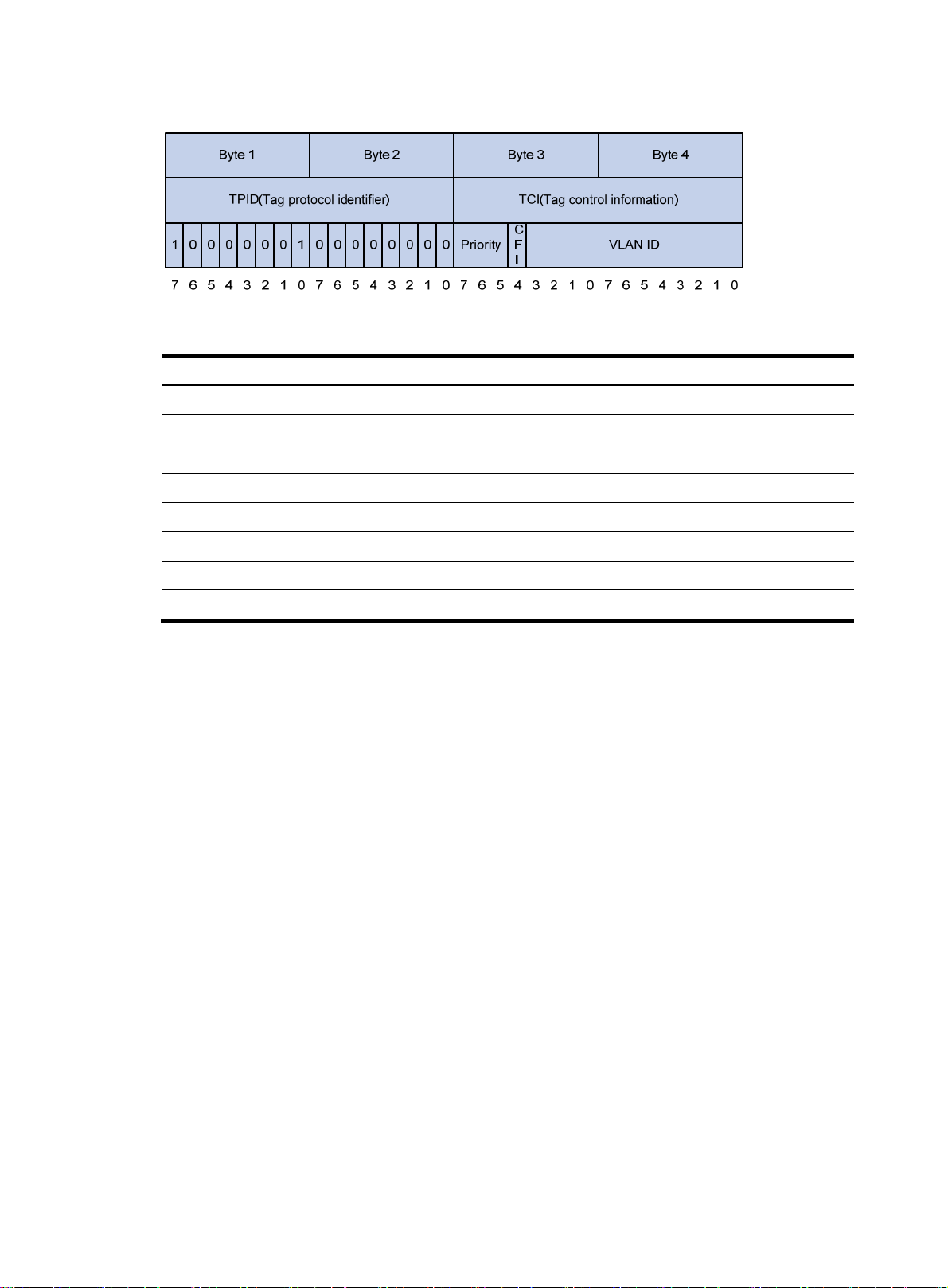
Figure 27 802.1Q tag header
p p
Table 10 Description on 802.1p priority
802.1
0 000 best-effort
1 001 background
2 010 spare
3 011 excellent-effort
4 100 controlled-load
5 101 video
6 110 voice
7 111 network-management
riority (decimal) 802.1p priority (binary) Description
Page 99

Configuring MPLS QoS
Overview
MPLS uses 3 bits, called EXP bits, ation to provide support for DiffServ.
MPLS QoS identifies different traffic and implements differentiated services.
MPLS QoS can guarantee low dela packet loss ratio for critical service traffic, such as voice
a
nd video traffic. For more information about MPLS, see MPLS Configuration Guide.
MPLS QoS supports CAR and priority m
• Classify traffic on the PE to apply differentiated QoS strategies for different traffic classes. For
example, MPLS QoS can organize packets with EXP value 1 into a class and
2 into another class. Then it performs traffic policing and priority marking for each class of packet
• When a PE labels a packet, it maps the IP prece
class information carried in the IP header is carried in the label.
The EXP field in an MPLS label is processed following these rules:
• The device re-sets the EXP field of only the topmost label.
• During label encapsulation, the ToS field of the IP packet is directly changed into the EXP field of the
MPLS label.
• The EXP field remains unchanged when label swapping is performe
Du
• ring a label push operation f the newly pushe el inherits the EXP field
o
f the inner label.
• After a label pop ket is the E
is not copied to the inner
copied to the ToS field
operation, if the pac still an MPLS packet, XP field of the popped label
to carry class-of-service inform
flows with different EXP bits
y and low
arking. MPLS QoS provides the following functions:
packets with EXP value
dence to the EXP field of the label. In this way, the
d.
, the EXP field o d outer lab
. If the packet is an IP packet,
label the E l is not
IP packet.
of the
XP field of the popped labe
s.
C q
onfiguration prere uisites
Before configuring MPLS Q
MPLS configurations, see MP
oS, com sic MPLS configuration. F e information about basic
plete ba
LS Co ation Guide.
nfigur
Configuring MPLS CAR
By configuring a CAR policy for traffic entering an MPLS network, you can limit the transmission rate to
avoid network congestion, rk pri inform
see "Configuring traffic policing
To configure MPLS CAR:
Step Command
1. Enter system view.
and ma ority for the traffic. For more ation about traffic policing,
, GTS, and rate limit."
system-view N/A
or mor
Remarks
97
Page 100

Step Command
2. Enter interface view.
3. Configure an MPLS CAR
policy for the interface.
interface interface-type
interface-number
qos car { inbound | outbound }
{ any | acl [ ipv6 ] acl-number } cir
committed-information-rate [ cbs
committed-burst-size [ ebs
excess-burst-size ] ] [ pir
peak-information-rate ] [ green
action | red action | yellow
action ] *
The action argument for MPLS can be:
• remark-mpls-exp-continue new-exp: Sets the EXP value to new-exp and continues to process the
packet using the next CAR policy. The new-exp is in the range of 0 to 7.
• remark-mpls-exp-pass new-exp: Sets the EXP value to new-exp and permits the packet to pass
through. The new-exp is in the range of 0 to 7.
Configuring MPLS priority marking
In an MPLS network, you can adjust the priority of an MPLS traffic flow by marking its EXP value. For more
information about priority marking, see "Configuring priority marking."
Remarks
N/A
By default, no CAR policy is
configured for an interface.
To configure the MPLS priority marking action for an MPLS traffic class:
Step Command
1. Enter system view.
2. Create a traffic class and
enter traffic class view.
3. Configure match criteria for
the traffic class.
4. Return to system view.
5. Create a traffic behavior and
enter traffic behavior view.
6. Configure an EXP marking
action in the traffic behavior.
7. Return to system view.
8. Create a QoS policy and
enter QoS policy view.
9. Associate the traffic class with
the traffic behavior in the QoS
policy.
system-view N/A
traffic classifier classifier-name
[ operator { and | or } ]
if-match [ not ] mpls-exp
exp-value&<1-8>
quit N/A
traffic behavior behavior-name
remark mpls-exp exp-value
quit
qos policy policy-name
classifier classifier-name behavior
behavior-name
Remarks
By default, no traffic class is
created.
By default, no match criteria are
configured.
The match criteria apply only to
MPLS packets.
By default, no traffic behavior is
created.
By default, no EXP marking action
is configured.
N/A
By default, no QoS policy is
created.
By default, no traffic behavior is
associated with a traffic class.
10. Return to system view.
quit N/A
98 99
 Loading...