

Page 1

HP MSR Router Series
MPLS
onfiguration Guide(V7)
C
Part number: 5998-5680
Software version: CMW710-R0106
Document version: 6PW100-20140607
Page 2

Legal and notice information
© Copyright 2014 Hewlett-Packard Development Company, L.P.
No part of this documentation may be reproduced or transmitted in any form or by any means without
prior written consent of Hewlett-Packard Development Company, L.P.
The information contained herein is subject to change without notice.
HEWLETT-PACKARD COMPANY MAKES NO WARRANTY OF ANY KIND WITH REGARD TO THIS
MATERIAL, INCLUDING, BUT NOT LIMITED TO, THE IMPLIED WARRANTIES OF MERCHANTABILITY
AND FITNESS FOR A PARTICULAR PURPOSE. Hewlett-Packard shall not be liable for errors contained
herein or for incidental or consequential damages in connection with the furnishing, performance, or
use of this material.
The only warranties for HP products and services are set forth in the express warranty statements
accompanying such products and services. Nothing herein should be construed as constituting an
additional warranty. HP shall not be liable for technical or editorial errors or omissions contained
herein.
Page 3

Contents
Configuring basic MPLS ·············································································································································· 1
Overview ············································································································································································ 1
Basic concepts ·························································································································································· 1
MPLS network architecture ······································································································································ 2
LSP establishment ······················································································································································ 3
MPLS forwarding ······················································································································································ 4
PHP ············································································································································································· 4
Protocols and standards ·········································································································································· 5
MPLS configuration task list ·············································································································································· 5
Enabling MPLS ··································································································································································· 5
Configuring MPLS MTU ···················································································································································· 6
Specifying the label type advertised by the egress ······································································································· 7
Configuring TTL propagation ··········································································································································· 7
Enabling sending of MPLS TTL-expired messages ········································································································· 9
Enabling MPLS forwarding statistics ······························································································································· 9
Enabling FTN forwarding statistics ························································································································· 9
Enabling MPLS label forwarding statistics ·········································································································· 10
Enabling SNMP notifications for MPLS ························································································································ 10
Displaying and maintaining MPLS ······························································································································· 10
Configuring a static LSP ············································································································································· 12
Overview ········································································································································································· 12
Configuration prerequisites ··········································································································································· 12
Configuration procedure ··············································································································································· 12
Displaying static LSPs ····················································································································································· 13
Static LSP configuration example ································································································································· 13
Configuring LDP ························································································································································· 16
Overview ········································································································································································· 16
Terminology ··························································································································································· 16
LDP messages ························································································································································· 16
LDP operation ························································································································································· 17
Label distribution and control ······························································································································· 18
LDP GR ···································································································································································· 20
LDP NSR ································································································································································· 21
LDP-IGP synchronization ······································································································································· 22
LDP FRR ··································································································································································· 23
Protocols ································································································································································· 23
LDP configuration task list ·············································································································································· 23
Enabling LDP ··································································································································································· 24
Enabling LDP globally ··········································································································································· 24
Enabling LDP on an interface ······························································································································· 25
Configuring Hello parameters ······································································································································ 25
Configuring LDP session parameters ···························································································································· 26
Configuring LDP backoff ··············································································································································· 27
Configuring LDP MD5 authentication ·························································································································· 27
Configuring LDP to redistribute BGP IPv4 unicast routes ··························································································· 28
Configuring an LSP generation policy ························································································································· 28
Configuring the LDP label distribution control mode ·································································································· 29
Configuring a label advertisement policy ··················································································································· 29
i
Page 4

Configuring a label acceptance policy ······················································································································· 30
Configuring LDP loop detection ···································································································································· 31
Configuring LDP session protection ······························································································································ 32
Configuring LDP GR ······················································································································································· 33
Configuring LDP NSR ····················································································································································· 33
Configuring LDP-IGP synchronization ·························································································································· 33
Configuring LDP-OSPF synchronization ·············································································································· 33
Configuring LDP-ISIS synchronization ················································································································· 35
Configuring LDP FRR ······················································································································································ 35
Specifying a DSCP value for outgoing LDP packets ··································································································· 36
Resetting LDP sessions ···················································································································································· 36
Enabling SNMP notifications for LDP ··························································································································· 36
Displaying and maintaining LDP ·································································································································· 36
LDP configuration examples ·········································································································································· 37
LDP LSP configuration example ···························································································································· 37
Label acceptance control configuration example ······························································································ 41
Label advertisement control configuration example ·························································································· 45
LDP FRR configuration example ··························································································································· 51
Configuring MPLS TE ················································································································································· 54
Overview ········································································································································································· 54
TE and MPLS TE ····················································································································································· 54
MPLS TE basic concepts········································································································································ 54
Static CRLSP establishment ··································································································································· 54
Dynamic CRLSP establishment ····························································································································· 54
Traffic forwarding ·················································································································································· 56
Make-before-break ················································································································································ 57
Route pinning ························································································································································· 58
Tunnel reoptimization ············································································································································ 58
Automatic bandwidth adjustment ························································································································ 59
CRLSP backup ························································································································································ 59
FRR ·········································································································································································· 59
DiffServ-aware TE ·················································································································································· 60
Bidirectional MPLS TE tunnel ································································································································ 62
Protocols and standards ······································································································································· 63
MPLS TE configuration task list ····································································································································· 63
Enabling MPLS TE ·························································································································································· 64
Configuring a tunnel interface ······································································································································ 65
Configuring DS-TE ·························································································································································· 65
Configuring an MPLS TE tunnel to use a static CRLSP ································································································ 66
Configuring an MPLS TE tunnel to use a dynamic CRLSP ·························································································· 66
Configuration task list ··········································································································································· 67
Configuring MPLS TE attributes for a link ··········································································································· 67
Advertising link TE attributes by using IGP TE extension ··················································································· 68
Configuring MPLS TE tunnel constraints ·············································································································· 69
Establishing an MPLS TE tunnel by using RSVP-TE ····························································································· 71
Controlling CRLSP path selection ························································································································· 71
Controlling MPLS TE tunnel setup ························································································································ 74
Configuring load sharing for an MPLS TE tunnel········································································································ 76
Configuring traffic forwarding ······································································································································ 77
Configuring static routing to direct traffic to an MPLS TE tunnel or tunnel bundle ········································· 77
Configuring PBR to direct traffic to an MPLS TE tunnel or tunnel bundle························································· 78
Configuring automatic route advertisement to direct traffic to an MPLS TE tunnel or tunnel bundle ············ 78
Configuring a bidirectional MPLS TE tunnel ················································································································ 80
Configuring CRLSP backup ··········································································································································· 81
ii
Page 5

Configuring MPLS TE FRR ·············································································································································· 81
Enabling FRR ·························································································································································· 81
Configuring a bypass tunnel on the PLR ············································································································· 82
Configuring node fault detection ························································································································· 85
Configuring the optimal bypass tunnel selection interval ·················································································· 86
Enabling SNMP notifications for MPLS TE ··················································································································· 86
Displaying and maintaining MPLS TE ·························································································································· 87
MPLS TE configuration examples ·································································································································· 87
Establishing an MPLS TE tunnel over a static CRLSP ·························································································· 87
Establishing an MPLS TE tunnel with RSVP-TE ···································································································· 92
Establishing an inter-AS MPLS TE tunnel with RSVP-TE ······················································································ 98
Bidirectional MPLS TE tunnel configuration example······················································································· 105
CRLSP backup configuration example ·············································································································· 111
Manual bypass tunnel for FRR configuration example ···················································································· 115
Auto FRR configuration example ······················································································································· 121
IETF DS-TE configuration example ····················································································································· 127
Troubleshooting MPLS TE ············································································································································ 134
No TE LSA generated ········································································································································· 134
Configuring a static CRLSP ····································································································································· 136
Overview ······································································································································································· 136
Configuration procedure ············································································································································· 136
Displaying static CRLSPs ·············································································································································· 137
Static CRLSP configuration example ·························································································································· 137
Configuring RSVP ···················································································································································· 143
Overview ······································································································································································· 143
RSVP messages ···················································································································································· 143
CRLSP setup procedure ······································································································································· 144
RSVP refresh mechanism ····································································································································· 144
RSVP authentication ············································································································································ 145
RSVP GR ······························································································································································· 145
Protocols and standards ····································································································································· 146
RSVP configuration task list ········································································································································· 146
Enabling RSVP ······························································································································································ 146
Configuring RSVP refresh ············································································································································ 147
Configuring RSVP Srefresh and reliable RSVP message delivery ··········································································· 147
Configuring RSVP hello extension ······························································································································ 147
Configuring RSVP authentication ································································································································ 148
Specifying a DSCP value for outgoing RSVP packets ······························································································ 150
Configuring RSVP GR ·················································································································································· 150
Enabling BFD for RSVP ················································································································································ 151
Displaying and maintaining RSVP ······························································································································ 151
RSVP configuration examples ····································································································································· 152
Establishing an MPLS TE tunnel with RSVP-TE ·································································································· 152
RSVP GR configuration example ······················································································································· 157
Configuring tunnel policies ····································································································································· 160
Overview ······································································································································································· 160
Configuring a tunnel policy ········································································································································ 160
Configuration guidelines ···································································································································· 160
Configuration procedure ···································································································································· 161
Displaying tunnel information ····································································································································· 162
Tunnel policy configuration examples ······················································································································· 162
Preferred tunnel configuration example ············································································································ 162
Exclusive tunnel configuration example ············································································································ 162
iii
Page 6

Tunnel selection order configuration example ································································································· 163
Preferred tunnel and tunnel selection order configuration example ······························································ 164
Configuring MPLS L3VPN ······································································································································· 166
Overview ······································································································································································· 166
Basic MPLS L3VPN architecture ························································································································· 166
MPLS L3VPN concepts ········································································································································ 167
MPLS L3VPN route advertisement ······················································································································ 168
MPLS L3VPN packet forwarding ························································································································ 169
MPLS L3VPN networking schemes ····················································································································· 170
Inter-AS VPN ························································································································································ 172
Carrier's carrier ··················································································································································· 176
Nested VPN ························································································································································· 178
HoVPN ·································································································································································· 179
OSPF VPN extension ··········································································································································· 181
BGP AS number substitution and SoO attribute ······························································································· 183
MPLS L3VPN FRR ················································································································································· 184
Multi-VPN instance CE ········································································································································ 186
Protocols and standards ····································································································································· 187
MPLS L3VPN configuration task list ···························································································································· 188
Configuring basic MPLS L3VPN ································································································································· 188
Configuration prerequisites ································································································································ 188
Configuring VPN instances ································································································································ 188
Configuring routing between a PE and a CE ··································································································· 190
Configuring routing between PEs ······················································································································ 196
Configuring BGP VPNv4 route control ············································································································· 196
Configuring inter-AS VPN ··········································································································································· 198
Configuring inter-AS option A ···························································································································· 198
Configuring inter-AS option B ···························································································································· 199
Configuring inter-AS option C···························································································································· 200
Configuring nested VPN ·············································································································································· 203
Configuring HoVPN ····················································································································································· 204
Configuring an OSPF sham link ································································································································· 205
Configuring a loopback interface ····················································································································· 205
Redistributing the loopback interface route ······································································································ 206
Creating a sham link ··········································································································································· 206
Configuring routing on an MCE ································································································································· 206
Configuring routing between an MCE and a VPN site ··················································································· 207
Configuring routing between an MCE and a PE ····························································································· 212
Specifying the VPN label processing mode on the egress PE ················································································· 215
Configuring BGP AS number substitution and SoO attribute ·················································································· 216
Enabling SNMP notifications for MPLS L3VPN ········································································································· 216
Configuring MPLS L3VPN FRR ···································································································································· 217
Displaying and maintaining MPLS L3VPN ················································································································ 219
MPLS L3VPN configuration examples ························································································································ 221
Configuring basic MPLS L3VPN ························································································································ 221
Configuring MPLS L3VPN over a GRE tunnel··································································································· 228
Configuring a hub-spoke network ····················································································································· 233
Configuring MPLS L3VPN inter-AS option A ···································································································· 239
Configuring MPLS L3VPN inter-AS option B ····································································································· 244
Configuring MPLS L3VPN inter-AS option C ···································································································· 249
Configuring MPLS L3VPN carrier's carrier ······································································································· 256
Configuring nested VPN ····································································································································· 263
Configuring HoVPN ············································································································································ 273
Configuring an OSPF sham link ························································································································ 280
iv
Page 7

Configuring MCE ················································································································································ 284
Configuring BGP AS number substitution ········································································································· 290
Configuring BGP AS number substitution and SoO attribute ········································································· 293
Configuring MPLS L3VPN FRR through VPNv4 route backup for a VPNv4 route ········································ 296
Configuring MPLS L3VPN FRR through VPNv4 route backup for an IPv4 route ··········································· 298
Configuring MPLS L3VPN FRR through IPv4 route backup for a VPNv4 route ············································· 300
Configuring IPv6 MPLS L3VPN ······························································································································ 303
Overview ······································································································································································· 303
IPv6 MPLS L3VPN packet forwarding ··············································································································· 304
IPv6 MPLS L3VPN routing information advertisement ····················································································· 304
IPv6 MPLS L3VPN network schemes and functions ·························································································· 305
Protocols and standards ····································································································································· 305
IPv6 MPLS L3VPN configuration task list ··················································································································· 305
Configuring basic IPv6 MPLS L3VPN ························································································································· 305
Configuring VPN instances ································································································································ 306
Configuring routing between a PE and a CE ··································································································· 308
Configuring routing between PEs ······················································································································ 313
Configuring BGP VPNv6 route control ············································································································· 313
Configuring inter-AS IPv6 VPN ··································································································································· 314
Configuring inter-AS IPv6 VPN option A ·········································································································· 315
Configuring inter-AS IPv6 VPN option C ·········································································································· 315
Configuring routing on an MCE ································································································································· 316
Configuring routing between an MCE and a VPN site ··················································································· 316
Configuring routing between an MCE and a PE ····························································································· 321
Configuring BGP AS number substitution and SoO attribute ·················································································· 325
Displaying and maintaining IPv6 MPLS L3VPN ········································································································ 325
IPv6 MPLS L3VPN configuration examples ··············································································································· 327
Configuring IPv6 MPLS L3VPNs ························································································································· 327
Configuring an IPv6 MPLS L3VPN over a GRE tunnel ···················································································· 334
Configuring IPv6 MPLS L3VPN inter-AS option A ···························································································· 338
Configuring IPv6 MPLS L3VPN inter-AS option C ···························································································· 343
Configuring IPv6 MPLS L3VPN carrier's carrier ······························································································· 350
Configuring IPv6 MCE ········································································································································ 358
Configuring BGP AS number substitution ········································································································· 363
Configuring BGP AS number substitution and SoO attribute ········································································· 368
Configuring MPLS L2VPN ······································································································································· 371
Overview ······································································································································································· 371
Basic concepts of MPLS L2VPN ························································································································· 371
MPLS L2VPN network models ···························································································································· 372
Remote connection establishment ······················································································································ 373
Local connection establishment ·························································································································· 374
PW types ······························································································································································ 374
Control word ························································································································································ 376
MPLS L2VPN interworking ·································································································································· 377
PW redundancy ··················································································································································· 377
Multi-segment PW ················································································································································ 378
VCCV ···································································································································································· 380
MPLS L2VPN configuration task list ···························································································································· 380
Enabling L2VPN ··························································································································································· 381
Configuring an AC ······················································································································································ 381
Configuring the interface with Ethernet or VLAN encapsulation ···································································· 381
Configuring the interface with PPP encapsulation ··························································································· 382
Configuring the interface with HDLC encapsulation························································································ 382
v
Page 8

Configuring a cross-connect ······································································································································· 382
Configuring a PW ························································································································································ 383
Configuring a PW class ······································································································································ 383
Configuring a static PW ····································································································································· 383
Configuring an LDP PW ······································································································································ 384
Configuring a BGP PW ······································································································································ 384
Configuring a remote CCC connection ············································································································ 386
Binding an AC to a cross-connect ······························································································································ 387
Configuring PW redundancy ······································································································································ 388
Configuring static PW redundancy ··················································································································· 388
Configuring LDP PW redundancy ······················································································································ 388
Configuring interworking for a cross-connect ··········································································································· 389
Displaying and maintaining MPLS L2VPN ················································································································ 390
MPLS L2VPN configuration examples ························································································································ 391
Configuring local MPLS L2VPN connections ···································································································· 391
Configuring IP interworking over local MPLS L2VPN connections ································································· 392
Configuring a static PW ····································································································································· 393
Configuring an LDP PW ······································································································································ 397
Configuring IP interworking over an LDP PW ·································································································· 401
Configuring a BGP PW ······································································································································ 405
Configuring a remote CCC connection ············································································································ 408
Configuring an intra-domain multi-segment PW ······························································································ 412
Configuring an inter-domain multi-segment PW ······························································································ 415
Configuring MPLS OAM ········································································································································· 422
Overview ······································································································································································· 422
MPLS ping ···························································································································································· 422
MPLS traceroute ··················································································································································· 422
Periodic MPLS traceroute ···································································································································· 422
MPLS BFD ····························································································································································· 423
Protocols and standards ·············································································································································· 423
Configuring MPLS OAM for LSP tunnels ···················································································································· 423
Configuring MPLS ping for LSPs ························································································································ 424
Configuring MPLS traceroute for LSPs ··············································································································· 424
Configuring periodic MPLS traceroute for LSPs ································································································ 424
Configuring MPLS BFD for LSPs ························································································································· 424
Configuring MPLS OAM for MPLS TE tunnels ··········································································································· 425
Configuring MPLS ping for MPLS TE tunnels ···································································································· 425
Configuring MPLS traceroute for MPLS TE tunnels ··························································································· 425
Configuring MPLS BFD for MPLS TE tunnels ····································································································· 426
Configuring MPLS OAM for a PW ····························································································································· 426
Configuring MPLS ping for a PW ······················································································································ 427
Configuring BFD for a PW ································································································································· 427
Displaying MPLS OAM ················································································································································ 429
BFD for LSP configuration example ···························································································································· 429
Configuring MPLS protection switching ················································································································· 432
Overview ······································································································································································· 432
Protection switching triggering modes ·············································································································· 432
Protection switching modes ································································································································ 433
Path switching modes·········································································································································· 433
Protocols and standards ·············································································································································· 433
MPLS protection switching configuration task list ····································································································· 434
Enabling MPLS protection switching ·························································································································· 434
Creating a protection group ······································································································································· 435
vi
Page 9

Configuring PS attributes for the protection group ··································································································· 436
Configuring command switching for the protection group ······················································································ 437
Configuring the PSC message sending interval ········································································································ 437
Displaying and maintaining MPLS protection switching ·························································································· 437
MPLS protection switching configuration example ··································································································· 438
Support and other resources ·································································································································· 442
Contacting HP ······························································································································································ 442
Subscription service ············································································································································ 442
Related information ······················································································································································ 442
Documents ···························································································································································· 442
Websites ······························································································································································· 442
Conventions ·································································································································································· 443
vii
Page 10
Configuring basic MPLS
In this chapter, "MSR2000" refers to MSR2003. "MSR3000" collectively refers to MSR3012, MSR3024,
MSR3044, MSR3064. "MSR4000" collectively refers to MSR4060 and MSR4080.
Overview
Multiprotocol Label Switching (MPLS) provides connection-oriented label switching over connectionless IP
backbone networks. It integrates both the flexibility of IP routing and the simplicity of Layer 2 switching.
MPLS has the following advantages:
• High speed and efficiency—MPLS uses short- and fixed-length labels to forward packets, avoiding
complicated routing table lookups.
• Multiprotocol support—MPLS resides between the link layer and the network layer. It can work over
various link layer protocols (for example, PPP, ATM, frame relay, and Ethernet) to provide
connection-oriented services for various network layer protocols (for example, IPv4, IPv6, and IPX).
• Good scalability—The connection-oriented switching and multilayer label stack features enable
MPLS to deliver various extended services, such as VPN, traffic engineering, and QoS.
Basic concepts
FEC
MPLS groups packets with the same characteristics (such as packets with the same destination or service
class) into a forwarding equivalence class (FEC). Packets of the same FEC are handled in the same way
on an MPLS network.
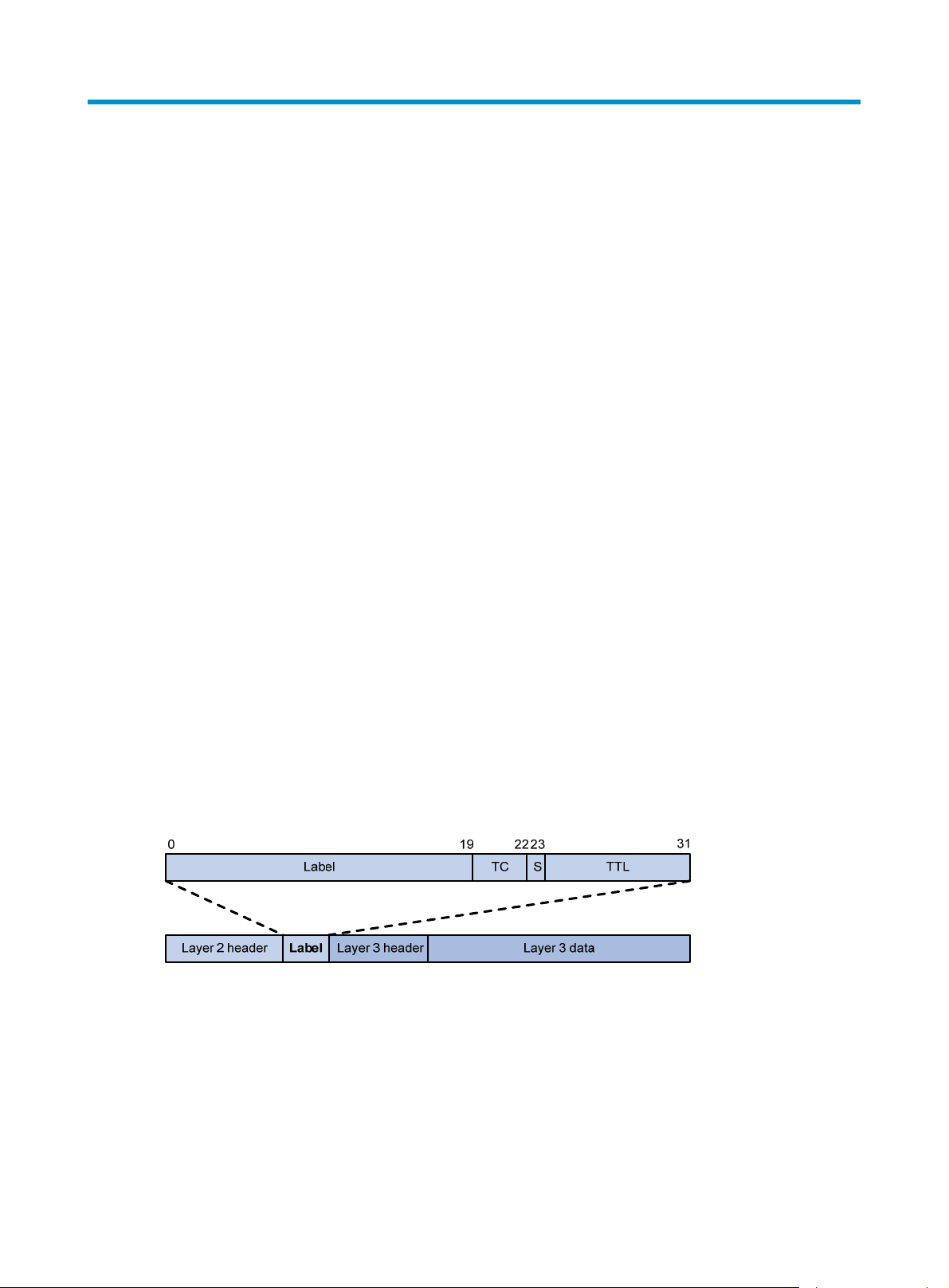
Label
A label uniquely identifies an FEC and has local significance.
Figure 1 Format of a label
A label is encapsulated between the Layer 2 header and Layer 3 header of a packet. It is four bytes long
and consists of the following fields:
• Label—20-bit label value.
• TC—3-bit traffic class, used for QoS. It is also called Exp.
• S—1-bit bottom of stack flag. A label stack can contain multiple labels. The label nearest to the
Layer 2 header is called the top label, and the label nearest to the Layer 3 header is called the
bottom label. The S field is set to 1 if the label is the bottom label and set to 0 if not.
• TTL—8-bit time to live field used for routing loop prevention.
1
Page 11
LSR
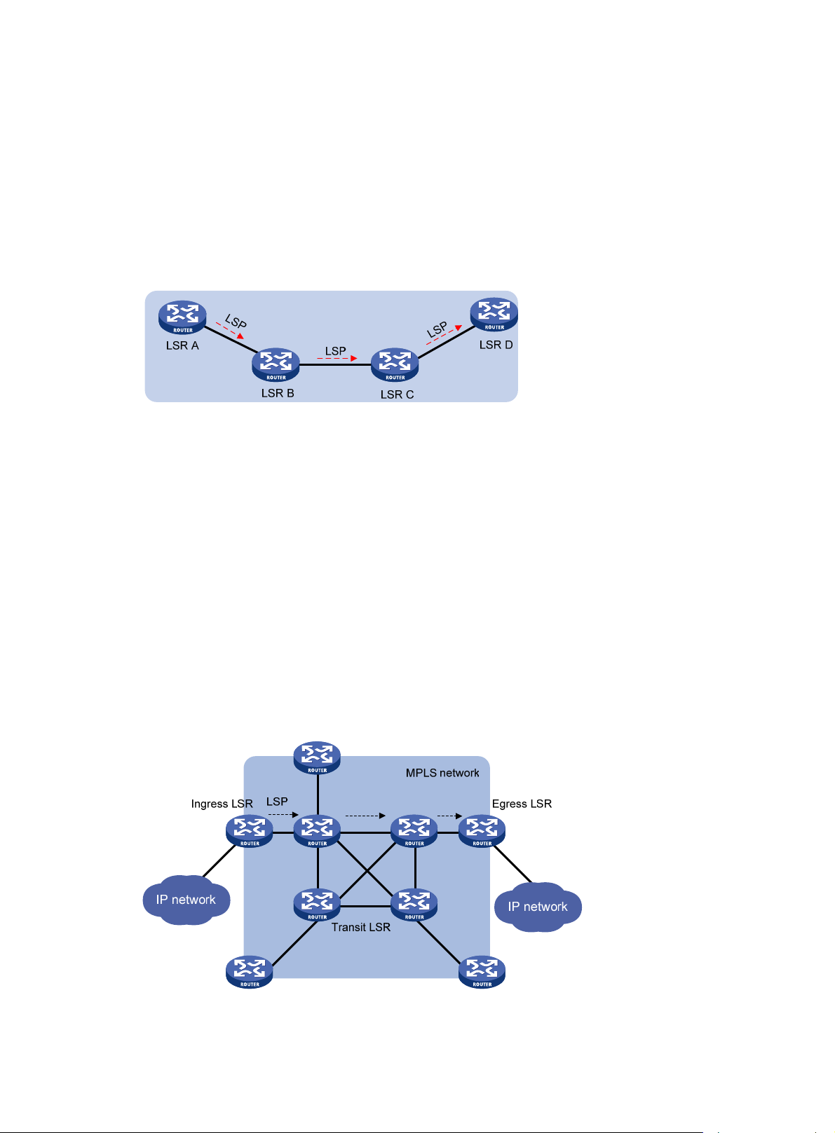
LSP
LFIB
A router that performs MPLS forwarding is a label switching router (LSR).
A label switched path (LSP) is the path along which packets of an FEC travel through an MPLS network.
An LSP is a unidirectional packet forwarding path. Two neighboring LSRs are called the upstream LSR
and downstream LSR along the direction of an LSP. In Figure 2,
R A is the upstream LSR of LSR B.
LS
Figure 2 Label switched path
The Label Forwarding Information Base (LFIB) on an MPLS network functions like the Forwarding
Information Base (FIB) on an IP network. When an LSR receives a labeled packet, it searches the LFIB to
obtain information for forwarding the packet, such as the label operation type, the outgoing label value,
and the next hop.
LSR B is the downstream LSR of LSR A, and
Control plane and forwarding plane
An MPLS node consists of a control plane and a forwarding plane.
• Control plane—Assigns labels, distributes FEC-label mappings to neighbor LSRs, creates the LFIB,
and establishes and removes LSPs.
• Forwarding plane—Forwards packets according to the LFIB.
MPLS network architecture
Figure 3 MPLS network architecture
An MPLS network has the following types of LSRs:
2
Page 12
• Ingress LSR—Ingress LSR of packets. It labels packets entering into the MPLS network.
• Transit LSR—Intermediate LSRs in the MPLS network. The transit LSRs on an LSP forward packets to
the egress LSR according to labels.
• Egress LSR—Egress LSR of packets. It removes labels from packets and forwards the packets to their
destination networks.
LSP establishment
LSPs include static and dynamic LSPs.
• Static LSP—To establish a static LSP, you must configure an LFIB entry on each LSR along the LSP.
Establishing static LSPs consumes fewer resources than establishing dynamic LSPs, but static LSPs
cannot automatically adapt to network topology changes. Therefore, static LSPs are suitable for
small-scale networks with simple, stable topologies.
• Dynamic LSP—Established by a label distribution protocol (also called an MPLS signaling protocol).
A label distribution protocol classifies FECs, distributes FEC-label mappings, and establishes and
maintains LSPs. Label distribution protocols include protocols designed specifically for label
distribution, such as the Label Distribution Protocol (LDP), and protocols extended to support label
distribution, such as MP-BGP and RSVP-TE.
In this document, the term "label distribution protocols" refers to all protocols for label distribution. The
term "LDP" refers to the RFC 5036 LDP.
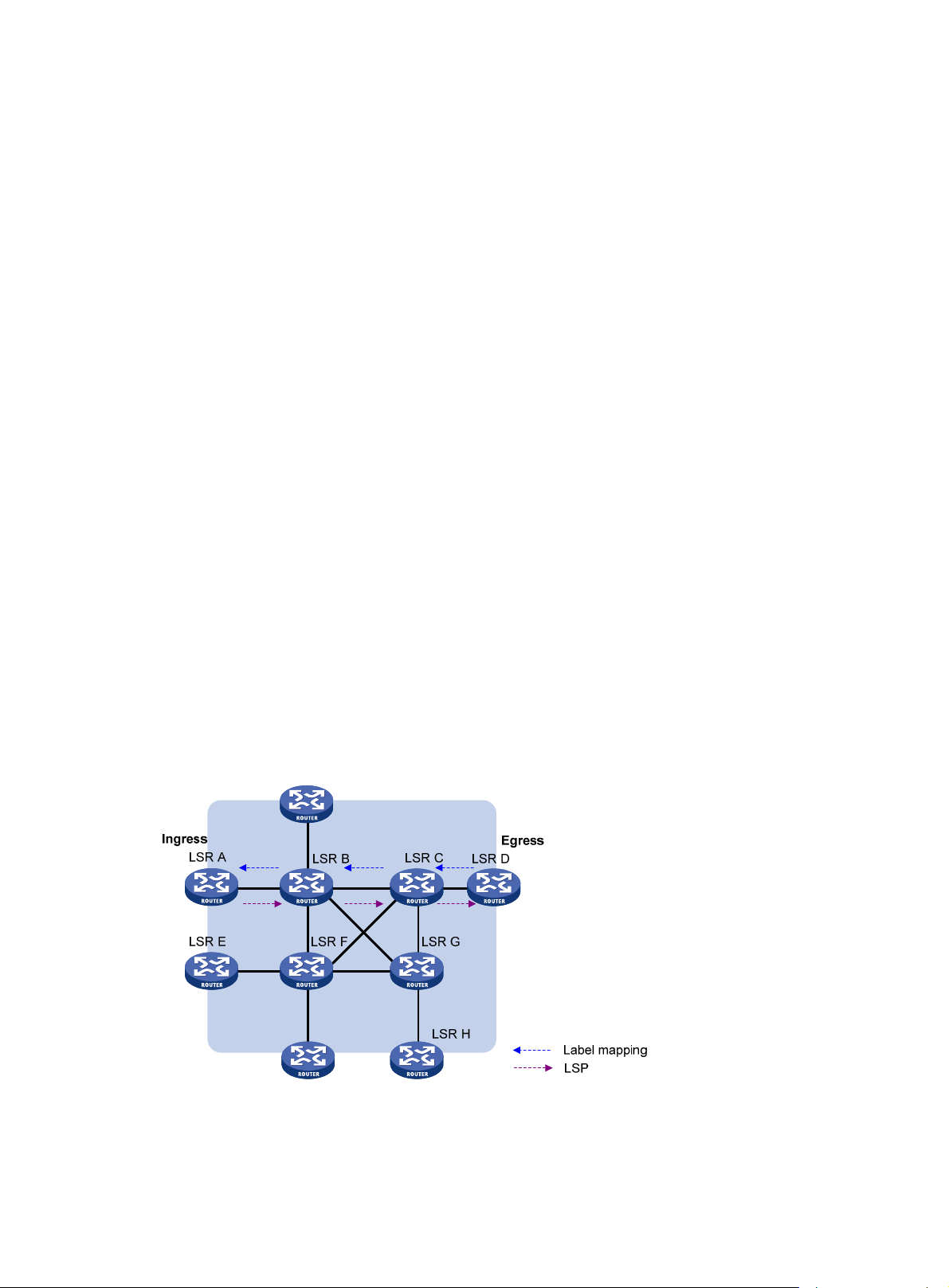
A dynamic LSP is established in the following steps:
1. A downstream LSR classifies FECs according to destination addresses.
2. The downstream LSR assigns a label for each FEC, and distributes the FEC-label binding to its
upstream LSR.
3. The upstream LSR establishes an LFIB entry for the FEC according to the binding information.
After all LSRs along the LSP establish an LFIB entry for the FEC, a dynamic LSP is established for the
packets of this FEC.
Figure 4 Dynamic LSP establishment
3
Page 13
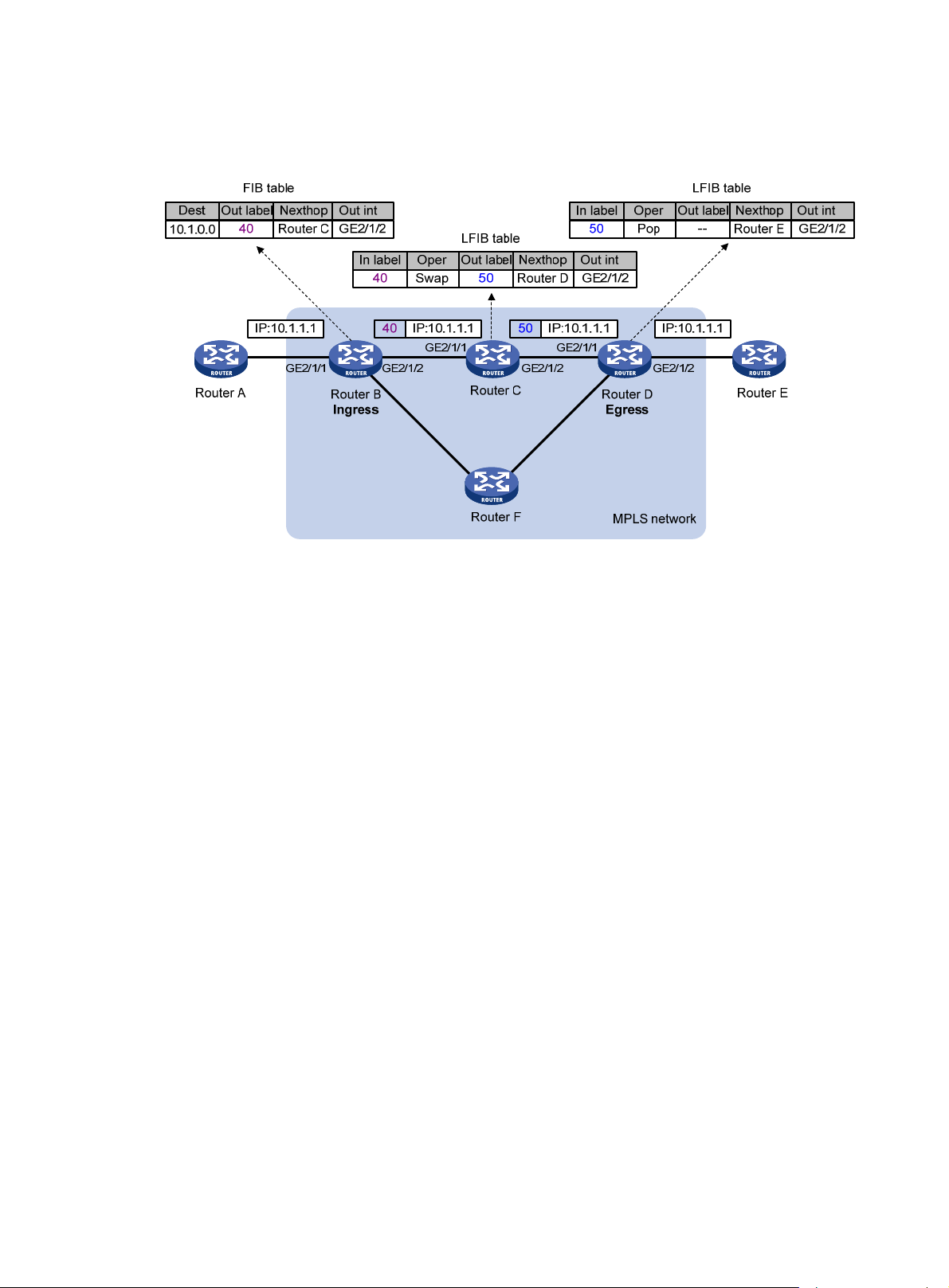
MPLS forwarding
Figure 5 MPLS forwarding
As shown in Figure 5, a packet is forwarded over the MPLS network as follows:
1. Router B (the ingress LSR) receives a packet with no label. It then does the following:
a. Identifies the FIB entry that matches the destination address of the packet.
b. Adds the outgoing label (40, in this example) to the packet.
c. Forwards the labeled packet out of the interface GigabitEthernet 2/1/2 to the next hop LSR
Router C.
2. When receiving the labeled packet, Router C processes the packet as follows:
a. Identifies the LFIB entry that has an incoming label of 40.
b. Uses the outgoing label 50 of the entry to replace label 40 in the packet.
c. Forwards the labeled packet out of the outgoing interface GigabitEthernet 2/1/2 to the next
hop LSR Router D.
3. When receiving the labeled packet, Router D (the egress) processes the packet as follows:
a. Identifies the LFIB entry that has an incoming label of 50.
b. Removes the label from the packet.
c. Forwards the packet out of the outgoing interface GigabitEthernet 2/1/2 to the next hop LSR
Router E.
If the LFIB entry records no outgoing interface or next hop information, Router D does the following:
d. Identifies the FIB entry by the IP header.
e. Forwards the packet according to the FIB entry.
PHP
An egress node must perform two forwarding table lookups to forward a packet:
• Two LFIB lookups (if the packet has more than one label).
4
Page 14

• One LFIB lookup and one FIB lookup (if the packet has only one label).
The penultimate hop popping (PHP) feature can pop the label at the penultimate node, so the egress
node only performs one table lookup.
A PHP-capable egress node sends the penultimate node an implicit null label of 3. This label never
appears in the label stack of packets. If an incoming packet matches an LFIB entry comprising the implicit
null label, the penultimate node pops the top label of the packet and forwards the packet to the egress
LSR. The egress LSR directly forwards the packet.
Sometimes, the egress node must use the TC field in the label to perform QoS. To keep the TC information,
you can configure the egress node to send the penultimate node an explicit null label of 0. If an incoming
packet matches an LFIB entry comprising the explicit null label, the penultimate hop replaces the value of
the top label with value 0, and forwards the packet to the egress node. The egress node gets the TC
information, pops the label of the packet, and forwards the packet.
Protocols and standards
• RFC 3031, Multiprotocol Label Switching Architecture
• RFC 3032, MPLS Label Stack Encoding
• RFC 5462, Multiprotocol Label Switching (MPLS) Label Stack Entry: "EXP" Field Renamed to "Traffic
Class" Field
MPLS configuration task list
Tasks at a glance
(Required.) Enabling MPLS
(Optional.) Configuring MPLS MTU
(Optional.) Specifying the label type advertised by the egress
(Optional.) Configuring TTL propagation
(Optional.) Enabling sending of MPLS TTL-expired messages
(Optional.) Enabling MPLS forwarding statistics
(Optional.) Enabling SNMP notifications for MPLS
Enabling MPLS
You must enable MPLS on all interfaces related to MPLS forwarding.
Before you enable MPLS, complete the following tasks:
• Configure link layer protocols to ensure connectivity at the link layer.
• Configure IP addresses for interfaces to ensure IP connectivity between neighboring nodes.
• Configure static routes or an IGP protocol to ensure IP connectivity among LSRs.To enable MPLS:
Step Command
1. Enter system view.
system-view
5
Remarks
N/A
Page 15

Step Command
2. Configure an LSR ID for the local
node.
3. Enter the view of the interface that
needs to perform MPLS
forwarding.
mpls lsr-id lsr-id
interface interface-type
interface-number
Remarks
By default, no LSR ID is configured.
An LSR ID must be unique in an MPLS
network and in IP address format. HP
recommends that you use the IP
address of a loopback interface as
an LSR ID.
N/A
4. Enable MPLS on the interface.
mpls enable
Configuring MPLS MTU
MPLS adds the label stack between the link layer header and network layer header of each packet. To
make sure the size of MPLS labeled packets is smaller than the MTU of an interface, configure an MPLS
MTU on the interface.
MPLS compares each MPLS packet against the interface MPLS MTU. When the packet exceeds the MPLS
MTU:
• If fragmentation is allowed, MPLS does the following:
a. Removes the label stack from the packet.
b. Fragments the IP packet. The length of a fragment is the MPLS MTU minus the length of the label
stack.
c. Adds the label stack to each fragment, and forwards the fragments.
• If fragmentation is not allowed, the LSR drops the packet.
To configure an MPLS MTU for an interface:
Step Command
5. Enter system view.
system-view N/A
By default, MPLS is disabled on the
interface.
Remarks
6. Enter interface view.
7. Configure an MPLS MTU for
the interface.
interface interface-type
interface-number
mpls mtu value
N/A
By default, no MPLS MTU is
configured on an interface.
The following applies when an interface handles MPLS packets:
• MPLS packets carrying L2VPN or IPv6 packets are always forwarded by an interface, even if the
length of the MPLS packets exceeds the MPLS MTU of the interface. Whether the forwarding can
succeed depends on the actual forwarding capacity of the interface.
• If the MPLS MTU of an interface is greater than the MTU of the interface, data forwarding might fail
on the interface.
• If you do not configure the MPLS MTU of an interface, fragmentation of MPLS packets is based on
the MTU of the interface without considering MPLS labels. An MPLS fragment might be larger than
the interface MTU and be dropped.
6
Page 16

Specifying the label type advertised by the egress
In an MPLS network, an egress can advertise the following types of labels:
• Implicit null label with a value of 3.
• Explicit null label with a value of 0.
• Non-null label.
For LSPs established by a label distribution protocol, the label advertised by the egress determines how
the penultimate hop processes a labeled packet.
• If the egress advertises an implicit null label, the penultimate hop directly pops the top label of a
matching packet.
• If the egress advertises an explicit null label, the penultimate hop swaps the top label value of a
matching packet with the explicit null label.
• If the egress advertises a non-null label (normal label), the penultimate hop swaps the top label of
a matching packet with the specific label assigned by the egress.
Configuration guidelines
If the penultimate hop supports PHP, HP recommends that you configure the egress to advertise an
implicit null label to the penultimate hop. If you want to simplify packet forwarding on the egress but keep
labels to determine QoS policies, configure the egress to advertise an explicit null label to the
penultimate hop. HP recommends using non-null labels only in particular scenarios. For example, when
OAM is configured on the egress, the egress can get the OAM function entity status only through non-null
labels.
As a penultimate hop, the device accepts the implicit null label, explicit null label, or normal label
advertised by the egress device.
For LDP LSPs, the mpls label advertise command triggers LDP to delete the LSPs established before the
command is executed and reestablishes new LSPs.
For BGP LSPs, the mpls label advertise command takes effect only on the BGP LSPs established after the
command is executed. To apply the new setting to BGP LSPs established before the command is executed,
delete the routes corresponding to the BGP LSPs, and then redistribute the routes.
Configuration procedure
To specify the type of label that the egress node will advertise to the penultimate hop:
Step Command
1. Enter system view.
2. Specify the label type
advertised by the egress to the
penultimate hop.
system-view N/A
mpls label advertise { explicit-null
| implicit-null | non-null }
Configuring TTL propagation
When TTL propagation is enabled, the ingress node copies the TTL value of an IP packet to the TTL field
of the label. Each LSR on the LSP decreases the label TTL value by 1. The LSR that pops the label copies
the remaining label TTL value back to the IP TTL of the packet, so the IP TTL value can reflect how many
Remarks
By default, an egress advertises an
implicit null label to the penultimate
hop.
7
Page 17
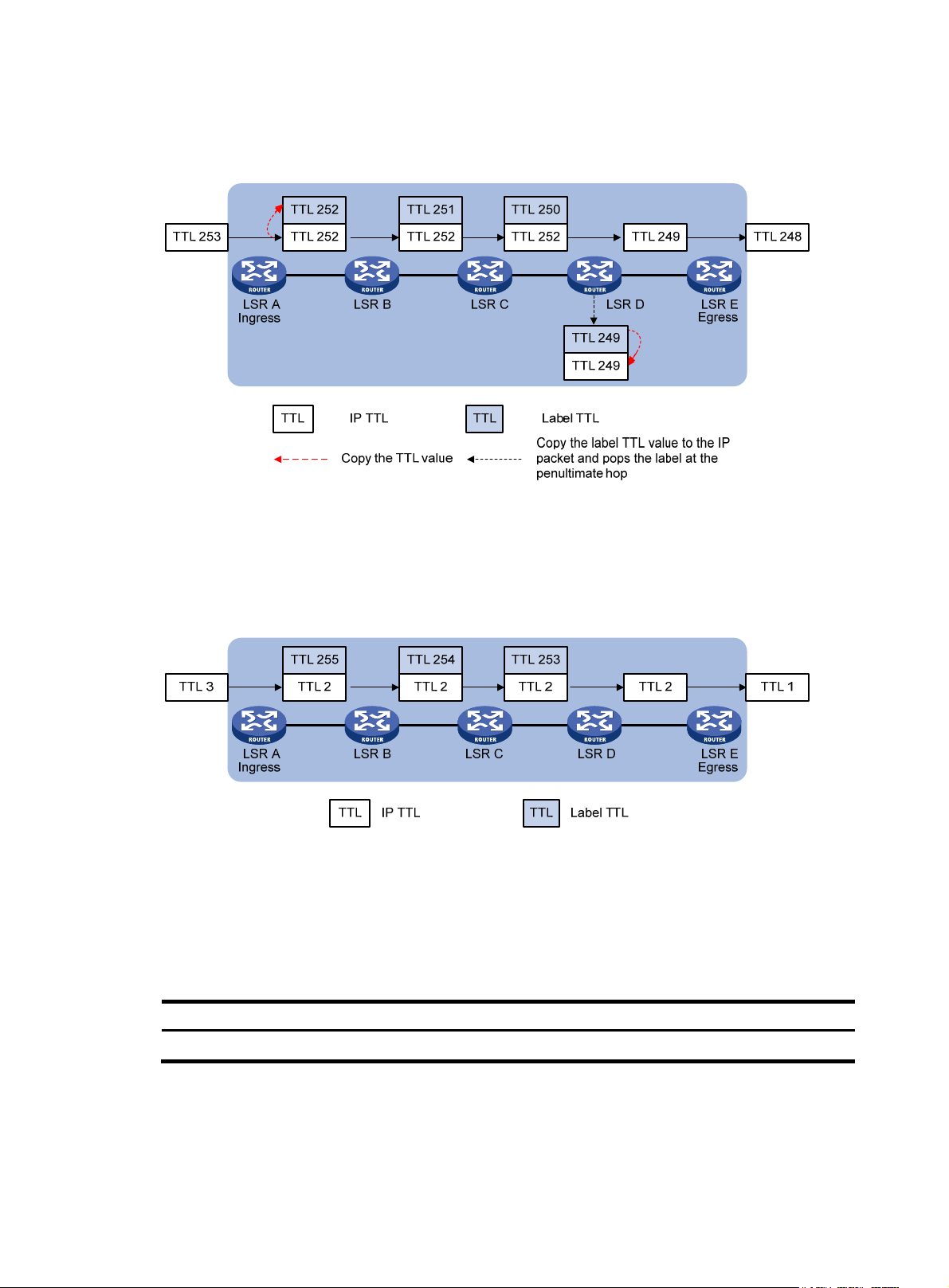
hops the packet has traversed in the MPLS network. The IP tracert facility can show the real path along
which the packet has traveled.
Figure 6 TTL propagation
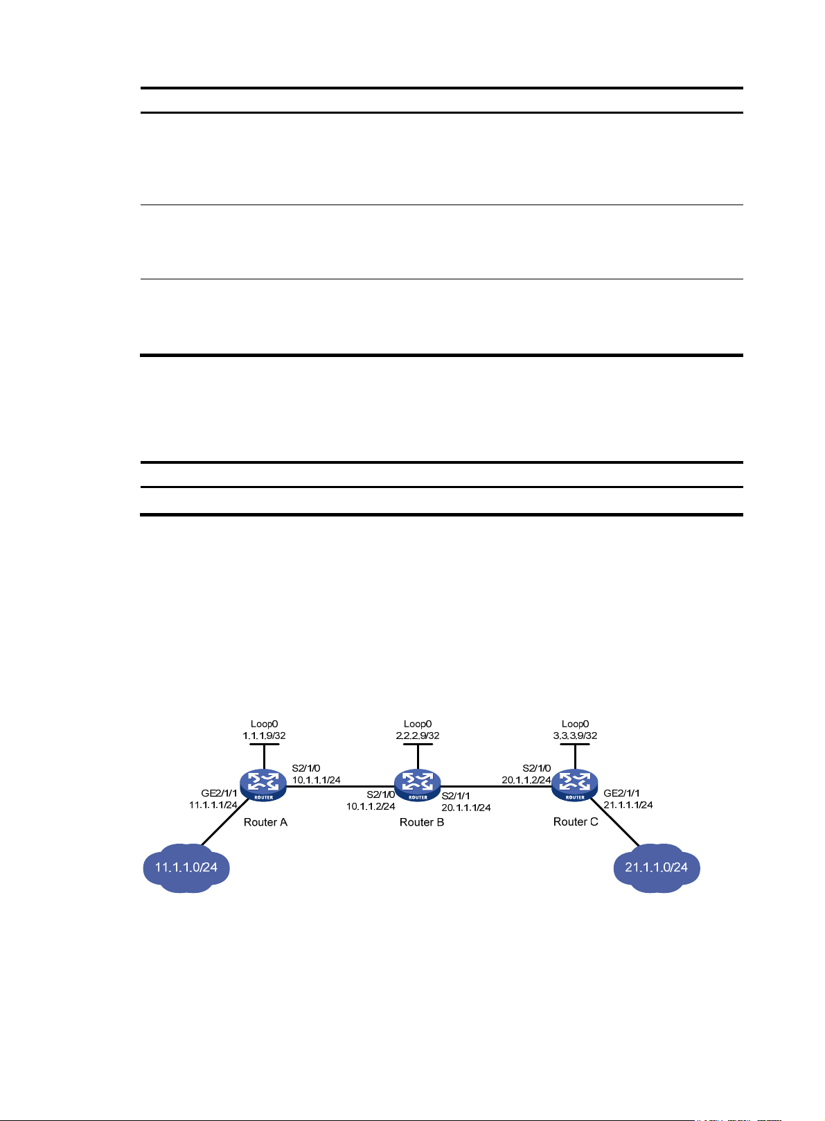
When TTL propagation is disabled, the ingress node sets the label TTL to 255. Each LSR on the LSP
decreases the label TTL value by 1. The LSR that pops the label does not change the IP TTL value when
popping the label. Therefore, the MPLS backbone nodes are invisible to user networks, and the IP tracert
facility cannot show the real path in the MPLS network.
Figure 7 Without TTL propagation
Follow these guidelines when you configure TTL propagation:
• HP recommends setting the same TTL processing mode on all LSRs of an LSP.
• To enable TTL propagation for a VPN, you must enable it on all PE devices in the VPN, so that you
can get the same traceroute result (hop count) from those PEs.
To enable TTL propagation:
Step Command
1. Enter system view.
system-view N/A
Remarks
8
Page 18

Step Command
2. Enable TTL propagation.
mpls ttl propagate { public |
vpn }
Remarks
By default, TTL propagation is enabled only
for public-network packets.
This command affects only the propagation
between IP TTL and label TTL. Within an
MPLS network, TTL is always copied between
the labels of an MPLS packet.
Enabling sending of MPLS TTL-expired messages
This feature enables an LSR to generate an ICMP TTL-expired message upon receiving an MPLS packet
with a TTL of 1. If the MPLS packet has only one label, the LSR sends the ICMP TTL-expired message back
to the source through IP routing. If the MPLS packet has multiple labels, the LSR sends it along the LSP to
the egress, which then sends the message back to the source.
To enable sending of MPLS TTL-expired messages:
Step Command
1. Enter system view.
2. Enable sending of MPLS TTL-expired
messages.
system-view N/A
mpls ttl expiration enable By default, this function is enabled.
Enabling MPLS forwarding statistics
Enabling FTN forwarding statistics
FEC-to-NHLFE map (FTN) entries are FIB entries that contain outgoing labels used for FTN forwarding.
When an LSR receives an unlabeled packet, it searches for the corresponding FTN entry based on the
destination IP address. If a match is found, the LSR adds the outgoing label in the FTN entry to the packet
and forwards the labeled packet.
To enable FTN forwarding statistics:
Step Command
1. Enter system view.
2. Enter RIB view.
3. Create a RIB IPv4 address
family and enter RIB IPv4
address family view.
system-view N/A
rib
address-family ipv4
Remarks
Remarks
N/A
By default, no RIB IPv4 address
family is created.
4. Enable the device to maintain
FTN entries in the RIB.
5. Enable FTN forwarding
statistics for a destination
network.
ftn enable
mpls-forwarding statistics prefix-list
prefix-list-name
9
By default, the device does not
maintain FTN entries in the RIB.
By default, FTN forwarding
statistics is disabled for all
destination networks.
Page 19

Enabling MPLS label forwarding statistics
MPLS label forwarding forwards a labeled packet based on its incoming label.
Perform this task to enable MPLS label forwarding statistics and MPLS statistics reading, so that you can
use the display mpls lsp verbose command to view MPLS label statistics.
To enable MPLS label forwarding statistics:
Step Command
1. Enter system view.
2. Enable MPLS label
forwarding statistics for
specific LSPs.
3. Enable MPLS label statistics
reading, and specify the
reading interval.
system-view N/A
mpls statistics { all | [ vpn-instance
vpn-instance-name ] { ipv4
ipv4-destination mask-length | ipv6
ipv6-destination prefix-length } | static
| te ingress-lsr-id tunnel-id }
mpls statistics interval interval
Remarks
By default, MPLS label
forwarding statistics are disabled
for all LSPs.
By default, MPLS label statistics
reading is disabled.
Enabling SNMP notifications for MPLS
This feature enables MPLS to generate SNMP notifications. The generated SNMP notifications are sent to
the SNMP module.
For more information about SNMP notifications, see Network Management and Monitoring
Configuration Guide.
To enable SNMP notifications for MPLS:
Step Command
1. Enter system view.
system-view N/A
Remarks
2. Enable SNMP notifications
for MPLS.
snmp-agent trap enable mpls
Displaying and maintaining MPLS
Execute display commands in any view and reset commands in user view.
Task Command
Display MPLS interface information. display mpls interface [ interface-type interface-number ]
Display usage information for MPLS
labels.
Display LSP information.
display mpls label { label-value1 [ to label-value2 ] | all }
display mpls lsp [ egress | in-label label-value | ingress |
outgoing-interface interface-type interface-number | protocol { bgp
| ldp | local | rsvp-te | static | static-cr } | transit ] [ vpn-instance
vpn-instance-name ] [ ipv4-dest mask-length | ipv6 [ ipv6-dest
prefix-length ] ] [ verbose ]
10
By default, SNMP notifications for
MPLS are enabled.
Page 20

Task Command
Display MPLS Nexthop Information Base
(NIB) information.
display mpls nib [ nib-id ]
Display usage information about NIDs. display mpls nid [ nid-value1 [ to nid-value2 ] ]
Display LSP statistics. display mpls lsp statistics
Display MPLS summary information. display mpls summary
Display ILM entries
(MSR2000/MSR3000).
display mpls forwarding ilm [ label ]
Display ILM entries (MSR4000). display mpls forwarding ilm [ label ] [ slot slot-number ]
Display NHLFE entries
(MSR2000/MSR3000).
display mpls forwarding nhlfe [ nid ]
Display NHLFE entries (MSR4000). display mpls forwarding nhlfe [ nid ] [ slot slot-number ]
Clear MPLS forwarding statistics for the
specified LSPs.
reset mpls statistics { all | [ vpn-instance vpn-instance-name ] { ipv4
ipv4-destination mask-length | ipv6 ipv6-destination prefix-length }
| static | te ingress-lsr-id tunnel-id }
11
Page 21

Configuring a static LSP
Overview
A static label switched path (LSP) is established by manually specifying the incoming label and outgoing
label on each node (ingress, transit, or egress node) of the forwarding path.
Static LSPs consume fewer resources, but they cannot automatically adapt to network topology changes.
Therefore, static LSPs are suitable for small and stable networks with simple topologies.
Follow these guidelines to establish a static LSP:
• The ingress node does the following:
a. Determines an FEC for a packet according to the destination address.
b. Adds the label for that FEC into the packet.
c. Forwards the packet to the next hop or out of the outgoing interface.
Therefore, on the ingress node, you must specify the outgoing label for the destination address (the
FEC) and the next hop or the outgoing interface.
• A transit node swaps the label carried in a received packet with a specific label, and forwards the
packet to the next hop or out of the outgoing interface. Therefore, on each transit node, you must
specify the incoming label, the outgoing label, and the next hop or the outgoing interface.
• If the penultimate hop popping function is not configured, an egress node pops the incoming label
of a packet, and performs label forwarding according to the inner label or IP forwarding. Therefore,
on the egress node, you only need to specify the incoming label.
• The outgoing label specified on an LSR must be the same as the incoming label specified on the
directly-connected downstream LSR.
Configuration prerequisites
Before you configure a static LSP, complete the following tasks:
1. Identify the ingress node, transit nodes, and egress node of the LSP.
2. Enable MPLS on all interfaces that participate in MPLS forwarding. For more information, see
"Configuring basic MPLS."
3. Make sure the ingress node has a route to the destination address of the LSP. This is not required
on transit and egress nodes.
Configuration procedure
To configure a static LSP:
Step Command
1. Enter system view.
system-view
12
Remarks
N/A
Page 22
Step Command
static-lsp ingress lsp-name destination
2. Configure the
ingress node of the
static LSP.
3. Configure the transit
node of the static
LSP.
4. Configure the egress
node of the static
LSP.
dest-addr { mask | mask-length } { nexthop
next-hop-addr | outgoing-interface
interface-type interface-number } out-label
out-label
static-lsp transit lsp-name in-label in-label
{ nexthop next-hop-addr |
outgoing-interface interface-type
interface-number } out-label out-label
static-lsp egress lsp-name in-label in-label
Displaying static LSPs
Execute display commands in any view.
Task Command
Display static LSP information. display mpls static-lsp [ lsp-name lsp-name ]
Remarks
If you specify a next hop for the
static LSP, make sure the ingress
node has an active route to the
specified next hop address.
If you specify a next hop for the
static LSP, make sure the transit
node has an active route to the
specified next hop address.
You do not need to configure this
command if the outgoing label
configured on the penultimate hop
of the static LSP is 0 or 3.
Static LSP configuration example
Network requirements
Router A, Router B, and Router C all support MPLS.
Establish static LSPs between Router A and Router C, so that subnets 11.1.1.0 / 24 a n d 21.1.1.0 / 24 c a n
access each other over MPLS.
Figure 8 Network diagram
Configuration considerations
For an LSP, the outgoing label specified on an LSR must be identical with the incoming label specified on
the downstream LSR.
LSPs are unidirectional. You must configure an LSP for each direction of the data forwarding path.
13
Page 23

A route to the destination address of the LSP must be available on the ingress node, but it is not needed
on transit and egress nodes. Therefore, you do not need to configure a routing protocol to ensure IP
connectivity among all routers.
Configuration procedure
1. Configure IP addresses for all interfaces, including the loopback interfaces, as shown in Figure 8.
(Details not shown.)
2. Configure a static route to the destination address of each LSP:
# On Router A, configure a static route to network 21.1.1.0/24.
<RouterA> system-view
[RouterA] ip route-static 21.1.1.0 24 10.1.1.2
# On Router C, configure a static route to network 11.1.1.0/24.
<RouterC> system-view
[RouterC] ip route-static 11.1.1.0 255.255.255.0 20.1.1.1
3. Configure basic MPLS on the routers:
# Configure Router A.
[RouterA] mpls lsr-id 1.1.1.9
[RouterA] interface serial 2/1/0
[RouterA-Serial2/1/0] mpls enable
[RouterA-Serial2/1/0] quit
# Configure Router B.
[RouterB] mpls lsr-id 2.2.2.9
[RouterB] interface serial 2/1/0
[RouterB-Serial2/1/0] mpls enable
[RouterB-Serial2/1/0] quit
[RouterB] interface serial 2/1/1
[RouterB-Serial2/1/1] mpls enable
[RouterB-Serial2/1/1] quit
# Configure Router C.
[RouterC] mpls lsr-id 3.3.3.9
[RouterC] interface serial 2/1/0
[RouterC-Serial2/1/0] mpls enable
[RouterC-Serial2/1/0] quit
4. Configure a static LSP from Router A to Router C:
# Configure the LSP ingress node, Router A.
[RouterA] static-lsp ingress AtoC destination 21.1.1.0 24 nexthop 10.1.1.2 out-label
30
# Configure the LSP transit node, Router B.
[RouterB] static-lsp transit AtoC in-label 30 nexthop 20.1.1.2 out-label 50
# Configure the LSP egress node, Router C.
[RouterC] static-lsp egress AtoC in-label 50
5. Create a static LSP from Router C to Router A:
# Configure the LSP ingress node, Router C.
[RouterC] static-lsp ingress CtoA destination 11.1.1.0 24 nexthop 20.1.1.1 out-label
40
# Configure the LSP transit node, Router B.
14
Page 24

[RouterB] static-lsp transit CtoA in-label 40 nexthop 10.1.1.1 out-label 70
# Configure the LSP egress node, Router A.
[RouterA] static-lsp egress CtoA in-label 70
Verifying the configuration
# Display static LSP information on routers, for example, on Router A.
[RouterA] display mpls static-lsp
Total: 2
Name FEC In/Out Label Nexthop/Out Interface State
AtoC 21.1.1.0/24 NULL/30 10.1.1.2 Up
CtoA -/- 70/NULL - Up
# Test the connectivity of the LSP from Router A to Router C.
[RouterA] ping mpls -a 11.1.1.1 ipv4 21.1.1.0 24
MPLS Ping FEC: 21.1.1.0/24 : 100 data bytes
100 bytes from 20.1.1.2: Sequence=1 time=4 ms
100 bytes from 20.1.1.2: Sequence=2 time=1 ms
100 bytes from 20.1.1.2: Sequence=3 time=1 ms
100 bytes from 20.1.1.2: Sequence=4 time=1 ms
100 bytes from 20.1.1.2: Sequence=5 time=1 ms
--- FEC: 21.1.1.0/24 ping statistics ---
5 packets transmitted, 5 packets received, 0.0% packet loss
round-trip min/avg/max = 1/1/4 ms
# Test the connectivity of the LSP from Router C to Router A.
[RouterC] ping mpls -a 21.1.1.1 ipv4 11.1.1.0 24
MPLS Ping FEC: 11.1.1.0/24 : 100 data bytes
100 bytes from 10.1.1.1: Sequence=1 time=5 ms
100 bytes from 10.1.1.1: Sequence=2 time=1 ms
100 bytes from 10.1.1.1: Sequence=3 time=1 ms
100 bytes from 10.1.1.1: Sequence=4 time=1 ms
100 bytes from 10.1.1.1: Sequence=5 time=1 ms
--- FEC: 11.1.1.0/24 ping statistics ---
5 packets transmitted, 5 packets received, 0.0% packet loss
round-trip min/avg/max = 1/1/5 ms
15
Page 25

Configuring LDP
In this chapter, "MSR2000" refers to MSR2003. "MSR3000" collectively refers to MSR3012, MSR3024,
MSR3044, MSR3064. "MSR4000" collectively refers to MSR4060 and MSR4080.
Overview
The Label Distribution Protocol (LDP) dynamically distributes FEC-label mapping information between
LSRs to establish LSPs.
Terminology
LDP session
Two LSRs establish a TCP-based LDP session to exchange FEC-label mappings.
LDP peer
Two LSRs that use LDP to exchange FEC-label mappings are LSR peers.
Label spaces and LDP identifiers
Label spaces include the following types:
• Per-interface label space—Each interface uses a single, independent label space. Different
interfaces can use the same label values.
• Per-platform label space—Each LSR uses a single label space. The device only supports the
per-platform label space.
A six-byte LDP Identifier (LDP ID) identifies a label space on an LSR. It is in the format of <LSR ID>:<label
space number>, where:
• The LSR ID takes four bytes to identity the LSR.
• The label space number takes two bytes to identify a label space within the LSR.
A label space number of 0 indicates that the label space is a per-platform label space. A label space
number other than 0 indicates a per-interface label space.
FECs and FEC-label mappings
MPLS groups packets with the same characteristics (such as the same destination or service class) into a
class, called an "FEC." The packets of the same FEC are handled in the same way on an MPLS network.
LDP can classify FECs by destination IP address and by PW. This document describes FEC classification
by destination IP address. For information about FEC classification by PW, see "Configuring MPLS
L2VPN."
An LSR assigns a label for an FEC and advertises the FEC-label mapping, or FEC-label binding, to its
peers in a Label Mapping message.
LDP messages
LDP mainly uses the following types of messages:
16
Page 26

• Discovery messages—Declare and maintain the presence of LSRs, such as Hello messages.
• Session messages—Establish, maintain, and terminate sessions between LDP peers, such as
Initialization messages used for parameter negotiation and Keepalive messages used to maintain
sessions.
• Advertisement messages—Create, alter, and remove FEC-label mappings, such as Label Mapping
messages used to advertise FEC-label mappings.
• Notification messages—Provide advisory information and notify errors, such as Notification
messages.
LDP uses UDP to transport discovery messages for efficiency, and uses TCP to transport session,
advertisement, and notification messages for reliability.
LDP operation
LDP operates in the following phases:
Discovering and maintaining LDP peers
LDP discovers peers in the following ways:
• Basic Discovery—Sends Link Hello messages to multicast address 224.0.0.2 that identifies all
routers on the subnet. All directly-connected LSRs can discover the LSR and establish a hello
adjacency.
• Extended Discovery—Sends LDP Targeted Hello messages to a specific IP address. The destination
LSR can discover the LSR and establish a hello adjacency. This mechanism is mainly used in MPLS
L2VPN and LDP over MPLS TE. For more information, see "Configuring MPLS L2VPN" and
"Configuring MPLS TE."
LDP can establish two hello adjacencies with a directly-connected neighbor through both discovery
mechanisms. It sends Hello messages at the hello interval to maintain a hello adjacency. If LDP receives
no Hello message from a hello adjacency before the hello hold timer expires, it removes the hello
adjacency.
Establishing and maintaining LDP sessions
LDP establishes a session with a peer in the following steps:
1. Establishes a TCP connection with the neighbor.
2. Negotiates session parameters such as LDP version, label distribution method, and Keepalive timer,
and establishes an LDP session with the neighbor if the negotiation succeeds.
After a session is established, LDP sends LDP PDUs (an LDP PDU carries one or more LDP messages) to
maintain the session. If no information is exchanged between the LDP peers within the Keepalive interval,
LDP sends Keepalive messages at the Keepalive interval to maintain the session. If LDP receives no LDP
PDU from a neighbor before the keepalive hold timer expires, or the last hello adjacency with the
neighbor is removed, LDP terminates the session.
LDP can also send a Shutdown message to a neighbor to terminate the LDP session.
Establishing LSPs
LDP classifies FECs according to destination IP addresses in IP routing entries, creates FEC-label
mappings, and advertises the mappings to LDP peers through LDP sessions. After an LDP peer receives
an FEC-label mapping, it uses the received label and the label locally assigned to that FEC to create an
LFIB entry for that FEC. When all LSRs (from the Ingress to the Egress) establish an LFIB entry for the FEC,
an LSP is established exclusively for the FEC.
17
Page 27
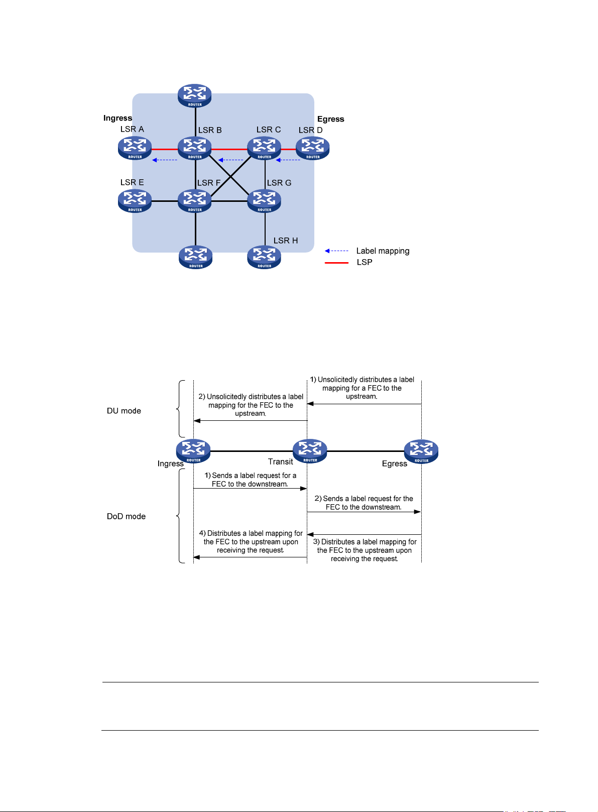
A
Figure 9 Dynamically establishing an LSP
Label distribution and control
Label advertisement modes
Figure 10 Label advertisement modes
LDP advertises label-FEC mappings in one of the following ways:
• Downstream Unsolicited (DU) mode—Distributes FEC-label mappings to the upstream LSR, without
waiting for label requests. The device supports only the DU mode.
• Downstream on Demand (DoD) mode—Sends a label request for an FEC to the downstream LSR.
After receiving the label request, the downstream LSR distributes the FEC-label mapping for that FEC
to the upstream LSR.
NOTE:
pair of upstream and downstream LSRs must use the same label advertisement mode. Otherwise, the
LSP cannot be established.
18
Page 28
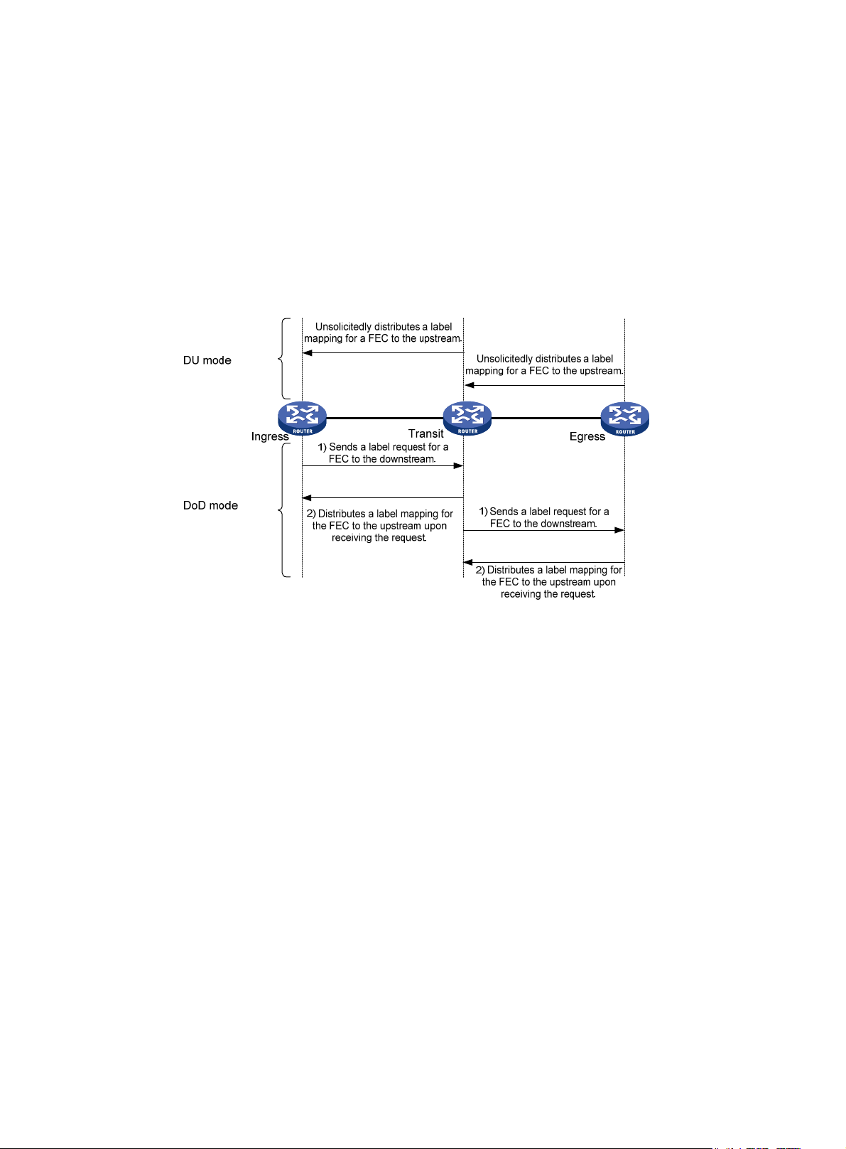
Label distribution control
LDP controls label distribution in one of the following ways:
• Independent label distribution—Distributes an FEC-label mapping to an upstream LSR at any time.
An LSR might distribute a mapping for an FEC to its upstream LSR before it receives a label mapping
for that FEC from its downstream LSR. As shown in Figure 11, in D
label mapping for an FEC to its upstream LSR whenever it is ready to label-switch the FEC, without
waiting for a label mapping for the FEC from its downstream LSR. In DoD mode, an LSR distributes
a label mapping for an FEC to its upstream LSR after it receives a label request for the FEC, without
waiting for a label mapping for the FEC from its downstream LSR.
Figure 11 Independent label distribution control mode
U mode, each LSR distributes a
• Ordered label distribution—Distributes a label mapping for an FEC to its upstream LSR only after it
receives a label mapping for that FEC from its downstream LSR unless the local node is the egress
node of the FEC. As shown in Figure 10, in D
to its upstream LSR only if it receives a label mapping for the FEC from its downstream LSR. In DoD
mode, when an LSR (Transit) receives a label request for an FEC from its upstream LSR (Ingress), it
continues to send a label request for the FEC to its downstream LSR (Egress). After the transit LSR
receives a label mapping for the FEC from the egress LSR, it distributes a label mapping for the FEC
to the ingress.
Label retention mode
The label retention mode specifies whether an LSR maintains a label mapping for an FEC learned from
a neighbor that is not its next hop.
• Liberal label retention—Retains a received label mapping for an FEC regardless of whether the
advertising LSR is the next hop of the FEC. This mechanism allows for quicker adaptation to
topology changes, but it wastes system resources because LDP has to keep useless labels. The
device only supports liberal label retention.
• Conservative label retention—Retains a received label mapping for an FEC only when the
advertising LSR is the next hop of the FEC. This mechanism saves label resources, but it cannot
quickly adapt to topology changes.
mode, an LSR distributes a label mapping for an FEC
U
19
Page 29
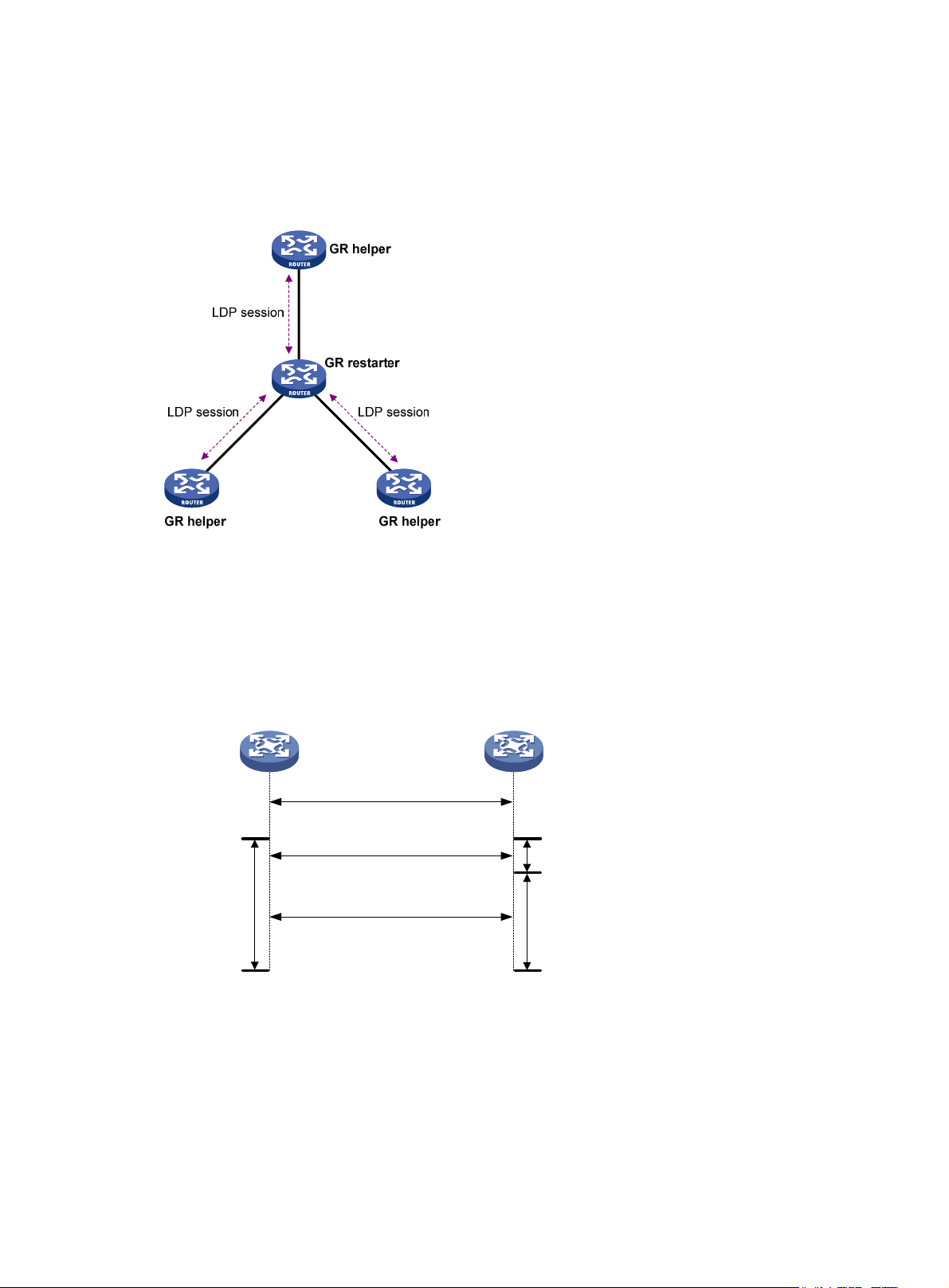
LDP GR
LDP Graceful Restart enables an LSR to retain MPLS forwarding entries during an LDP restart, ensuring
continuous MPLS forwarding.
Figure 12 LDP GR
As shown in Figure 12, GR defines the following roles:
• GR restarter—An LSR that performs GR. It must be GR-capable.
• GR helper—A neighbor LSR that helps the GR restarter to complete GR.
The device can act as a GR restarter or a GR helper.
Figure 13 LDP GR operation
GR restarter
Protocol
restarts
MPLS
forwarding state
holding time
Set up an LDP session, and identify that
they are LDP GR capable
Re-establish the LDP session
Send label mappings
GR helper
Reconnect time
LDP recovery time
As shown in Figure 13, LDP GR works in the following steps:
1. LSRs establish an LDP session. The L flag of the Fault Tolerance TLV in their Initialization messages
is set to 1 to indicate that they support LDP GR.
2. When LDP restarts, the GR restarter starts the MPLS Forwarding State Holding timer, and marks the
MPLS forwarding entries as stale. When the GR helper detects that the LDP session to the GR
restarter goes down, it marks the FEC-label mappings learned from the session as stale and starts
the Reconnect timer received from the GR restarter.
20
Page 30

y
3. After LDP completes restart, the GR restarter reestablishes an LDP session to the GR helper. If the
4. After the LDP session is reestablished, the GR helper starts the LDP Recovery timer.
5. The GR restarter and the GR helper exchange label mappings and update their MPLS forwarding
6. When the MPLS Forwarding State Holding timer expires, the GR restarter deletes all stale MPLS
7. When the LDP Recovery timer expires, the GR helper deletes all stale FEC-label mappings.
LDP NSR
LDP session is not set up before the Reconnect timer expires, the GR helper deletes the stale
FEC-label mappings and the corresponding MPLS forwarding entries. If the LDP session is
successfully set up before the Reconnect timer expires, the GR restarter sends the remaining time of
the MPLS Forwarding State Holding timer as the LDP Recovery time to the GR helper.
tables.
The GR restarter compares each received label mapping against stale MPLS forwarding entries. If
a match is found, the restarter deletes the stale mark for the matching entry. Otherwise, it adds a
new entry for the label mapping.
The GR helper compares each received label mapping against stale FEC-label mappings. If a
match is found, the helper deletes the stale mark for the matching mapping. Otherwise, it adds the
received FEC-label mapping and a new MPLS forwarding entry for the mapping.
forwarding entries.
The following matrix shows the feature and hardware compatibility:
Hardware LDP NSR compatibilit
MSR2000 No
MSR3000 No
MSR4000 Yes
LDP nonstop routing (NSR) backs up protocol states and data (including LDP session and LSP information)
from the active process to the standby process. When the LDP primary process fails, the backup process
seamlessly takes over primary processing. The LDP peers are not notified of the LDP interruption. The LDP
peers keep the LDP session in Operational state, and the forwarding is not interrupted.
The LDP primary process fails when one of the following occurs:
• The primary process restarts.
• The MPU where the primary process resides fails.
• The MPU where the primary process resides performs an ISSU.
• The LDP process' position determined by the process placement function is different from the
position where the LDP process is operating.
Choose either LDP NSR or LDP GR to ensure continuous traffic forwarding:
• Device requirements
{ To use LDP NSR, the device must have two or more MPUs, and the primary and backup process
for LDP reside on different MPUs.
{ To use LDP GR, the device can have only one MPU on the device.
• LDP peer requirements
21
Page 31

{ With LDP NSR, LDP peers of the local device are not notified of any switchover event on the local
device. The local device does not require help from a peer to restore the MPLS forwarding
information.
{ With LDP GR, the LDP peer must be able to identify the GR capability flag (in the Initialization
mess age ) of the GR res tar ter. The L DP p eer acts as a GR hel per to h elp the GR res tar ter t o rest ore
MPLS forwarding information.
LDP-IGP synchronization
Basic operating mechanism
LDP establishes LSPs based on the IGP optimal route. If LDP is not synchronized with IGP, MPLS traffic
forwarding might be interrupted.
LDP is not synchronized with IGP when one of the following occurs:
• A link is up, and IGP advertises and uses this link. However, LDP LSPs on this link have not been
established.
• An LDP session on a link is down, and LDP LSPs on the link have been removed. However, IGP still
uses this link.
• The Ordered label distribution control mode is used. IGP used the link before the local device
received the label mappings from the downstream LSR to establish LDP LSPs.
After LDP-IGP synchronization is enabled, IGP advertises the actual cost of a link only when LDP
convergence on the link is completed. Before LDP convergence is completed, IGP advertises the
maximum cost of the link. In this way, the link is visible on the IGP topology, but IGP does not select this
link as the optimal route when other links are available. Therefore, the device can avoid discarding MPLS
packets when there is not an LDP LSP established on the optimal route.
LDP convergence on a link is completed when all the followings occur:
• The local device establishes an LDP session to at least one peer, and the LDP session is already in
Operational state.
• The local device has distributed the label mappings to at least one peer.
Notification delay for LDP convergence completion
By default, LDP immediately sends a notification to IGP that LDP convergence has completed. However,
immediate notifications might cause MPLS traffic forwarding interruptions in one of the following
scenarios:
• When LDP peers use the Ordered label distribution control mode, the device does not receive a
label mapping from downstream at the time LDP notifies IGP that LDP convergence has completed.
• When a large number of label mappings are distributed from downstream, label advertisement is
not completed when LDP notifies IGP that LDP convergence has completed.
To avoid traffic forwarding interruptions in these scenarios, configure the notification delay. When LDP
convergence on a link is completed, LDP waits before notifying IGP.
Notification delay for LDP restart or active/standby switchover
When an LDP restart or an active/standby switchover occurs, LDP takes time to converge, and LDP
notifies IGP of the LDP-IGP synchronization status as follows:
• If a notification delay is not configured, LDP immediately notifies IGP of the current synchronization
states during convergence, and then updates the states after LDP convergence. This could impact
IGP processing.
22
Page 32

• If a notification delay is configured, LDP notifies IGP of the LDP-IGP synchronization states in bulk
LDP FRR
A link or router failure on a path can cause packet loss until LDP establishes a new LSP on the new path.
LDP FRR enables fast rerouting to minimize the failover time. LDP FRR is based on IP FRR and is enabled
automatically after IP FRR is enabled.
You can use one of the following methods to enable IP FRR:
• Configure an IGP to automatically calculate a backup next hop.
• Configure an IGP to specify a backup next hop by using a routing policy.
Figure 14 Network diagram for LDP FRR
when one of the following events occurs:
{ LDP recovers to the status before the restart or switchover.
{ The maximum delay timer expires.
As shown in Figure 14, configure IP FRR on LSR A. The IGP automatically calculates a backup next hop
or it specifies a backup next hop through a routing policy. LDP creates a primary LSP and a backup LSP
according to the primary route and the backup route calculated by IGP. When the primary LSP operates
correctly, it forwards the MPLS packets. When the primary LSP fails, LDP directs packets to the backup
LSP.
When packets are forwarded through the backup LSP, IGP calculates the optimal path based on the new
network topology. When IGP route convergence occurs, LDP establishes a new LSP according to the
optimal path. If a new LSP is not established after IGP route convergence, traffic forwarding might be
interrupted. Therefore, HP recommends that you enable LDP-IGP synchronization to work with LDP FRR to
reduce traffic interruption.
Protocols
RFC 5036, LDP Specification
LDP configuration task list
Tasks at a glance
Enable LDP:
1. (Required.) Enabling LDP globally
2. (Requir
ed.) Enabling LDP on an interface
23
Page 33

Tasks at a glance
(Optional.) Configuring Hello parameters
(Optional.) Configuring LDP session parameters
(Optional.) Configuring LDP backoff
(Optional.) Configuring LDP MD5 authentication
(Optional.) Configuring LDP to redistribute BGP IPv4 unicast routes
(Optional.) Configuring an LSP generation policy
(Optional.) Configuring the LDP label distribution control mode
(Optional.) Configuring a label advertisement policy
(Optional.) Configuring a label acceptance policy
(Optional.) Configuring LDP loop detection
(Optional.) Configuring LDP session protection
(Optional.) Configuring LDP GR
(Optional.) Configuring LDP NSR
(Optional.) Configuring LDP-IGP synchronization
(Optional.) Configuring LDP FRR
(Optional.) Specifying a DSCP value for outgoing LDP packets
(Optional.) Resetting LDP sessions
(Optional.) Enabling SNMP notifications for LDP
Enabling LDP
To enable LDP, you must enable LDP globally. Then enable LDP on relevant interfaces or configure IGP to
automatically enable LDP on those interfaces.
Enabling LDP globally
Step Command
1. Enter system view.
2. Enable LDP for the local node
or for a VPN.
Remarks
system-view N/A
• Enable LDP for the local node and
enter LDP view:
mpls ldp
• Enable LDP for a VPN and enter
LDP-VPN instance view:
a. mpls ldp
b. vpn-instance vpn-instance-name
By default, LDP is disabled.
3. Configure an LDP LSR ID.
lsr-id lsr-id
24
By default, the LDP LSR ID is
the same as the MPLS LSR ID.
Page 34

Enabling LDP on an interface
Step Command
1. Enter system view.
2. Enter interface view.
3. Enable LDP on the interface.
system-view N/A
interface interface-type interface-number
mpls ldp enable
Configuring Hello parameters
Perform this task to configure the following hello timers:
• Link Hello hold time and Link Hello interval.
• Targeted Hello hold time and Targeted Hello interval for a specific peer.
Configuring Link Hello timers
Step Command
1. Enter system view.
2. Enter the view of the interface
where you want to establish an
LDP session.
system-view N/A
interface interface-type
interface-number
Remarks
If the interface is bound to a
VPN instance, you must
enable LDP for the VPN
instance by using the
vpn-instance command in
LDP view.
By default, LDP is disabled
on an interface.
Remarks
N/A
3. Configure the Link Hello hold
time.
4. Configure the Link Hello
interval.
mpls ldp timer hello-hold timeout
mpls ldp timer hello-interval
interval
Configuring Targeted Hello timers for an LDP peer
Step Command
1. Enter system view.
2. Enter LDP view.
3. Specify an LDP peer and enter
LDP peer view. The device will
send unsolicited Targeted Hellos
to the peer and can respond to
the Targeted Hellos sent from the
peer.
4. Configure the Targeted Hello
hold time.
5. Configure the Target Hello
interval.
system-view
mpls ldp N/A
targeted-peer peer-lsr-id
mpls ldp timer hello-hold timeout
mpls ldp timer hello-interval
interval
By default, the Link Hello hold time
is 15 seconds.
By default, the Link Hello interval is
5 seconds.
Remarks
N/A
By default, the device does not
send Targeted Hellos to or
receive Targeted Hellos from
any peer.
By default, the Targeted Hello
hold time is 45 seconds.
By default, the Targeted Hello
interval is 15 seconds.
25
Page 35

Configuring LDP session parameters
This task configures the following LDP session parameters:
• Keepalive hold time and Keepalive interval.
• LDP transport address—IP address for establishing TCP connections.
LDP uses Basic Discovery and Extended Discovery mechanisms to discovery LDP peers and establish LDP
sessions with them.
When you configure LDP session parameters, follow these guidelines:
• The configured LDP transport address must be the IP address of an up interface on the device.
Otherwise, no LDP session can be established.
• Make sure the LDP transport addresses of the local and peer LSRs can reach each other. Otherwise,
no TCP connection can be established.
Configuring LDP sessions parameters for Basic Discovery mechanism
Step Command
1. Enter system view.
2. Enter interface view.
3. Configure the Keepalive hold
time.
4. Configure the Keepalive
interval.
5. Configure the LDP transport
address.
system-view N/A
interface interface-type
interface-number
mpls ldp timer keepalive-hold
timeout
mpls ldp timer keepalive-interval
interval
mpls ldp transport-address
{ ip-address | interface }
Remarks
N/A
By default, the Keepalive hold time
is 45 seconds.
By default, the Keepalive interval is
15 seconds.
By default, the LDP transport
address is the LSR ID of the local
device if the interface where you
want to establish an LDP session
belongs to the public network. If
the interface belongs to a VPN, the
LDP transport address is the
primary IP address of the interface.
If the interface where you want to
establish an LDP session is bound
to a VPN instance, the interface
with the IP address specified with
this command must be bound to the
same VPN instance.
Configuring LDP sessions parameters for Extended Discovery mechanism
Step Command
1. Enter system view.
2. Enter LDP view.
system-view N/A
mpls ldp N/A
26
Remarks
Page 36

Step Command
3. Specify an LDP peer and enter
LDP peer view. The device will
send unsolicited Targeted Hellos
to the peer and can respond to
Targeted Hellos sent from the
targeted peer.
4. Configure the Keepalive hold
time.
5. Configure the Keepalive interval.
6. Configure the LDP transport
address.
targeted-peer peer-lsr-id
mpls ldp timer keepalive-hold
timeout
mpls ldp timer keepalive-interval
interval
mpls ldp transport-address
ip-address
Configuring LDP backoff
If LDP session parameters (for example, the label advertisement mode) are incompatible, two LDP peers
cannot establish a session, and they will keep negotiating with each other.
The LDP backoff mechanism can mitigate this problem by using an initial delay timer and a maximum
delay timer. After LDP fails to establish a session with a peer LSR for the first time, LDP does not start an
attempt until the initial delay timer expires. If the session setup fails again, LDP waits for two times the
initial delay before the next attempt, and so forth until the maximum delay time is reached. After that, the
maximum delay time will always take effect.
Remarks
By default, the device does not
send Targeted Hellos to or
receive Targeted Hellos from
any peer.
By default, the Keepalive hold
time is 45 seconds.
By default, the Keepalive interval
is 15 seconds.
By default, the LDP transport
address is the LSR ID of the local
device.
To configure LDP backoff:
Step Command
1. Enter system view.
system-view N/A
Remarks
• Enter LDP view:
mpls ldp
2. Enter LDP view or enter
LDP-VPN instance view.
3. Configure the initial delay time
and maximum delay time.
• Enter LDP-VPN instance view:
a. mpls ldp
b. vpn-instance
vpn-instance-name
backoff initial initial-time maximum
maximum-time
N/A
By default, the initial delay time is
15 seconds, and the maximum
delay time is 120 seconds.
Configuring LDP MD5 authentication
To improve security for LDP sessions, you can configure MD5 authentication for the underlying TCP
connections to check the integrity of LDP messages.
For two LDP peers to establish an LDP session successfully, make sure the LDP MD5 authentication
configurations on the LDP peers are consistent.
To configure LDP MD5 authentication:
27
Page 37

Step Command
1. Enter system view.
system-view N/A
Remarks
• Enter LDP view:
2. Enter LDP view or enter
LDP-VPN instance view.
3. Enable LDP MD5
authentication.
mpls ldp
• Enter LDP-VPN instance view:
a. mpls ldp
b. vpn-instance vpn-instance-name
md5-authentication peer-lsr-id { cipher |
plain } password
N/A
By default, LDP MD5
authentication is disabled.
Configuring LDP to redistribute BGP IPv4 unicast routes
After LDP is enabled on a device, LDP can redistribute routes on the device, assign labels to the routes,
and establish LSPs.
By default, LDP automatically redistributes IGP routes and BGP routes that have been redistributed into
IGP. LDP cannot redistribute BGP routes if no IGP is configured or the BGP routes are not redistributed into
the IGP.
For example, on a carrier's carrier network where IGP is not configured between a PE of a Level 1 carrier
and a CE of a Level 2 carrier, LDP cannot redistribute BGP rou tes to as sig n la bel s to the m. For t his net work
to operate correctly, you can enable LDP to redistribute BGP IPv4 unicast routes on the PE and the CE. The
configuration enables LDP to assign labels to the BGP routes to establish LSPs. For more information
about carrier's carrier, see "Configuring MPLS L3VPN".
To configure LDP to redistribute BGP IPv4 unicast routes:
Step Command
1. Enter system view.
system-view
• Enter LDP view:
2. Enter LDP view or enter LDP-VPN
instance view.
3. Enable LDP to redistribute BGP
IPv4 unicast routes.
mpls ldp
• Enter LDP-VPN instance view:
a. mpls ldp
b. vpn-instance vpn-instance-name
import bgp
Configuring an LSP generation policy
Remarks
N/A
N/A
By default, LDP does not
redistribute BGP IPv4
unicast routes.
LDP assigns labels to t he routes that have be en redistri buted into LDP to generate LSPs. An LSP generation
policy specifies which redistributed routes can be used by LDP to generate LSPs to control the number of
LSPs, as follows:
• Use all routes to establish LSPs.
28
Page 38

• Use the routes permitted by an IP prefix list to establish LSPs. For information about IP prefix list
configuration, see Layer 3—IP Routing Configuration Guide.
• Use only host routes with a 32-bit mask to establish LSPs.
By default, LDP uses only host routes with a 32-bit mask to establish LSPs. The other two methods can
result in more LSPs than the default policy. To change the policy, be sure that the system resources and
bandwidth resources are sufficient.
To configure an LSP generation policy:
Step Command
1. Enter system view.
system-view N/A
Remarks
• Enter LDP view:
2. Enter LDP view or enter
LDP-VPN instance view.
3. Configure an LSP
generation policy.
mpls ldp
• Enter LDP-VPN instance view:
a. mpls ldp
b. vpn-instance vpn-instance-name
lsp-trigger { all | prefix-list
prefix-list-name }
N/A
By default, LDP uses only the
redistributed routes with a 32-bit
mask to establish LSPs.
Configuring the LDP label distribution control mode
Step Command
1. Enter system view.
system-view N/A
• Enter LDP view:
2. Enter LDP view or enter
LDP-VPN instance view.
mpls ldp
• Enter LDP-VPN instance view:
a. mpls ldp
b. vpn-instance vpn-instance-name
Remarks
N/A
By default, the Ordered label
distribution mode is used.
3. Configure the label
distribution control mode.
label-distribution { independent |
ordered }
To apply the new setting to LDP
sessions established before the
command is configured, you must
reset the LDP sessions.
Configuring a label advertisement policy
A label advertisement policy uses IP prefix lists to control the FEC-label mappings advertised to peers.
As shown in Figure 15, LSR A advertises label mappings for FECs permitted by IP prefix list B to LSR B and
ad
vertises label mappings for FECs permitted by IP prefix list C to LSR C.
29
Page 39

Figure 15 Label advertisement control diagram
A label advertisement policy on an LSR and a label acceptance policy on its upstream LSR can achieve
the same purpose. HP recommends that you use label advertisement policies to reduce network load if
downstream LSRs support label advertisement control.
Before you configure an LDP label advertisement policy, create an IP prefix list. For information about IP
prefix list configuration, see Layer 3—IP Routing Configuration Guide.
To configure a label advertisement policy:
Step Command
1. Enter system view.
system-view N/A
Remarks
• Enter LDP view:
2. Enter LDP view or enter
LDP-VPN instance view.
3. Configure a label
advertisement policy.
mpls ldp
• Enter LDP-VPN instance view:
a. mpls ldp
b. vpn-instance vpn-instance-name
advertise-label prefix-list prefix-list-name
[ peer peer-prefix-list-name ]
N/A
By default, LDP advertises all
label mappings permitted by the
LSP generation policy to all peers.
Configuring a label acceptance policy
A label acceptance policy uses an IP prefix list to control the label mappings received from a peer.
As shown in Figure 16, LSR A uses an I P prefix list to filter label ma
label mappings from LSR C.
ppings from LSR B, and it does not filter
30
Page 40

Figure 16 Label acceptance control diagram
Do
no
t
m
filter label
apping
s
A label advertisement policy on an LSR and a label acceptance policy on its upstream LSR can achieve
the same purpose. HP recommends using the label advertisement policy to reduce network load.
You must create an IP prefix list before you configure a label acceptance policy. For information about IP
prefix list configuration, see Layer 3—IP Routing Configuration Guide.
To configure a label acceptance policy:
Step Command
1. Enter system view.
system-view N/A
• Enter LDP view:
2. Enter LDP view or enter
LDP-VPN instance view.
3. Configure a label
acceptance policy.
mpls ldp
• Enter LDP-VPN instance view:
a. mpls ldp
b. vpn-instance vpn-instance-name
accept-label peer peer-lsr-id prefix-list
prefix-list-name
Configuring LDP loop detection
LDP detects and terminate LSP loops in the following ways:
• Maximum hop count—LDP adds a hop count in a label request or label mapping message. The
hop count value increments by 1 on each LSR. When the maximum hop count is reached, LDP
considers that a loop has occurred and terminates the establishment of the LSP.
• Path vector—LDP adds LSR ID information in a label request or label mapping message. Each LSR
checks whether its LSR ID is contained in the message. If it is not, the LSR adds its own LSR ID into
the message. If it is, the LSR considers that a loop has occurred and terminates LSP establishment.
In addition, when the number of LSR IDs in the message reaches the path vector limit, LDP also
considers that a loop has occurred and terminates LSP establishment.
Remarks
N/A
By default, LDP accepts all label
mappings.
To configure LDP loop detection:
Step Command
1. Enter system view.
system-view N/A
31
Remarks
Page 41

Step Command
Remarks
• Enter LDP view:
2. Enter LDP view or enter
LDP-VPN instance view.
3. Enable loop detection.
4. Specify the maximum hop
count.
5. Specify the path vector limit.
mpls ldp
• Enter LDP-VPN instance view:
a. mpls ldp
b. vpn-instance vpn-instance-name
loop-detect
maxhops hop-number
pv-limit pv-number
N/A
By default, loop detection is
disabled.
After loop detection is
enabled, the device uses both
the maximum hop count and
the path vector methods to
detect loops.
By default, the maximum hop
count is 32.
By default, the path vector limit
is 32.
NOTE:
The LDP loop detection feature is applicable only in networks comprised of devices that do not support TTL
mechanism, such as ATM switches. Do not use LDP loop detection on other networks because it only results
in extra LDP overhead.
Configuring LDP session protection
If two LDP peers have both a direct link and an indirect link in between, you can configure this feature to
protect their LDP session when the direct link fails.
LDP establishes both a Link Hello adjacency over the direct link and a Targeted Hello adjacency over the
indirect link with the peer. When the direct link fails, LDP deletes the Link Hello adjacency but still
maintains the Targeted Hello adjacency. In this way, the LDP session between the two peers is kept
available, and the FEC-label mappings based on this session are not deleted. When the direct link
recovers, the LDP peers do not need to reestablish the LDP session or re-learn the FEC-label mappings.
When you enable the session protection function, you can also specify the session protection duration.
If the Link Hello adjacency does not recover within the duration, LDP deletes the Targeted Hello
adjacency and the LDP session. If you do not specify the session protection duration, the two peers will
always maintain the LDP session over the Targeted Hello adjacency.
To configure LDP session protection:
Step Command
1. Enter system view.
2. Enter LDP view.
3. Enable the session protection
function.
system-view N/A
mpls ldp N/A
session protection [ duration time ]
[ peer peer-prefix-list-name ]
Remarks
By default, session protection is
disabled.
32
Page 42

y
Configuring LDP GR
Before you configure LDP GR, enable LDP on the GR restarter and GR helpers.
To configure LDP GR:
Step Command
1. Enter system view.
2. Enter LDP view.
3. Enable LDP GR.
4. Configure the Reconnect
timer for LDP GR.
5. Configure the MPLS
Forwarding State Holding
timer for LDP GR.
system-view N/A
mpls ldp N/A
graceful-restart By default, LDP GR is disabled.
graceful-restart timer reconnect
reconnect-time
graceful-restart timer forwarding-hold
hold-time
Configuring LDP NSR
The following matrix shows the feature and hardware compatibility:
Hardware LDP NSR compatibilit
MSR2000 No
MSR3000 No
MSR4000 Yes
Remarks
By default, the Reconnect time is
120 seconds.
By default, the MPLS Forwarding
State Holding time is 180 seconds.
To configure LDP NSR:
Step Command
1. Enter system view.
2. Enter LDP view.
3. Enable LDP NSR.
system-view N/A
mpls ldp N/A
non-stop-routing By default, LDP NSR is disabled.
Remarks
Configuring LDP-IGP synchronization
After you enable LDP-IGP synchronization for an OSPF process, OSPF area, or an IS-IS process, LDP-IGP
synchronization is enabled on the OSPF process interfaces or the IS-IS process interfaces.
You can execute the mpls ldp igp sync disable command to disable LDP-IGP synchronization on
interfaces where LDP-IGP synchronization is not required.
Configuring LDP-OSPF synchronization
LDP-IGP synchronization is not supported for an OSPF process and its OSPF areas if the OSPF process
belongs to a VPN instance.
33
Page 43

To configure LDP-OSPF synchronization for an OSPF process:
Step Command
1. Enter system view.
2. Enter OSPF view.
3. Enable LDP-OSPF
synchronization.
4. Return to system view.
5. Enter interface view.
6. (Optional.) Disable LDP-IGP
synchronization on the
interface.
7. Return to system view.
8. Enter LDP view.
9. (Optional.) Set the delay for
LDP to notify IGP of the LDP
convergence.
10. (Optional.) Set the maximum
delay for LDP to notify IGP of
the LDP-IGP synchronization
status after an LDP restart or
active/standby switchover.
system-view N/A
ospf [ process-id | router-id
router-id ] *
mpls ldp sync
quit N/A
interface interface-type
interface-number
mpls ldp igp sync disable
quit N/A
mpls ldp N/A
igp sync delay time
igp sync delay on-restart time
Remarks
N/A
By default, LDP-OSPF synchronization
is disabled.
N/A
By default, LDP-IGP synchronization is
not disabled on an interface.
By default, LDP immediately notifies
IGP of the LDP convergence
completion.
By default, the maximum notification
delay is 90 seconds.
To configure LDP-OSPF synchronization for an OSPF area:
Step Command
1. Enter system view.
2. Enter OSPF view.
3. Enter area view.
4. Enable LDP-OSPF
synchronization.
5. Return to system view.
6. Enter interface view.
7. (Optional.) Disable LDP-IGP
synchronization on the
interface.
8. Return to system view.
9. Enter LDP view.
10. (Optional.) Set the delay for
LDP to notify IGP of the LDP
convergence.
system-view N/A
ospf [ process-id | router-id
router-id ] *
area area-id N/A
mpls ldp sync
quit N/A
interface interface-type
interface-number
mpls ldp igp sync disable
quit N/A
mpls ldp N/A
igp sync delay time
Remarks
N/A
By default, LDP-OSPF synchronization
is disabled.
N/A
By default, LDP-IGP synchronization is
enabled on an interface.
By default, LDP immediately notifies
IGP of the LDP convergence
completion.
34
Page 44

Step Command
11. (Optional.) Set the maximum
delay for LDP to notify IGP of
the LDP-IGP synchronization
status after an LDP restart or
active/standby switchover.
igp sync delay on-restart time
Configuring LDP-ISIS synchronization
LDP-IGP synchronization is not supported for an IS-IS process that belongs to a VPN instance.
To configure LDP-ISIS synchronization for an IS-IS process:
Step Command
1. Enter system view.
2. Enter IS-IS view.
3. Enable LDP-ISIS
synchronization.
4. Return to system view.
5. Enter interface view.
system-view N/A
isis [ process-id ] N/A
mpls ldp sync [ level-1 |
level-2 ]
quit N/A
interface interface-type
interface-number
Remarks
By default, the maximum notification
delay is 90 seconds.
Remarks
By default, LDP-ISIS synchronization is
disabled.
N/A
6. (Optional.) Disable LDP-IGP
synchronization on the
interface.
7. Return to system view.
8. Enter LDP view.
9. (Optional.) Set the delay for
LDP to notify IGP of the LDP
convergence completion.
10. (Optional.) Set the maximum
delay for LDP to notify IGP of
the LDP-IGP synchronization
status after an LDP restart or an
active/standby switchover
occurs.
Configuring LDP FRR
LDP FRR is based on IP FRR, and is enabled automatically after IP FRR is enabled. For information about
configuring IP FRR, see Layer 3—IP Routing Configuration Guide.
By default, LDP-IGP synchronization is
enabled on an interface.
mpls ldp igp sync disable
quit N/A
mpls ldp N/A
igp sync delay time
igp sync delay on-restart time
Whether an interface is LDP-IGP
synchronization-capable depends on
the IGP configuration.
By default, LDP immediately notifies
IGP of the LDP convergence
completion.
By default, the maximum notification
delay is 90 seconds.
35
Page 45

Specifying a DSCP value for outgoing LDP packets
To control the transmission preference of outgoing LDP packets, specify a DSCP value for outgoing LDP
packets.
To specify a DSCP value for outgoing LDP packets:
Step Command
1. Enter system view.
2. Enter LDP view.
3. Specify a DSCP value for
outgoing LDP packets.
system-view N/A
mpls ldp N/A
dscp dscp-value
Remarks
By default, the DSCP value for outgoing
LDP packets is 48.
Resetting LDP sessions
Changes to LDP session parameters do not take effect on existing LDP sessions. To validate the changes,
you must reset the LDP sessions.
Execute the reset mpls ldp command in user view.
Task Command
Reset LDP sessions. reset mpls ldp [ vpn-instance vpn-instance-name ] [ peer peer-id ]
Enabling SNMP notifications for LDP
This feature enables generating SNMP notifications for LDP upon LDP session changes, as defined in RFC
3815. The generated SNMP notifications are sent to the SNMP module.
To enable SNMP notifications for LDP:
Step Command
1. Enter system view.
2. Enable SNMP notifications
for LDP.
system-view N/A
snmp-agent trap enable ldp
For more information about SNMP notifications, see Network Management and Monitoring
Configuration Guide.
Displaying and maintaining LDP
Execute display commands in any view.
Task Command
Display LDP discovery information
(MSR2000/MSR3000).
display mpls ldp discovery [ vpn-instance vpn-instance-name ]
[ interface interface-type interface-number | peer peer-lsr-id |
targeted-peer peer-lsr-id ] [ verbose ]
36
Remarks
By default, SNMP notifications for
LDP are enabled.
Page 46

Task Command
Display LDP discovery information
(MSR4000).
Display LDP FEC-label mapping
information (MSR2000/MSR3000).
Display LDP FEC-label mapping
information (MSR4000).
Display LDP-IGP synchronization
information.
Display LDP interface information.
Display LDP LSP information.
Display LDP running parameters. display mpls ldp parameter [ vpn-instance vpn-instance-name ]
Display LDP peer and session
information (MSR2000/MSR3000).
Display LDP peer and session
information (MSR4000).
Display LDP summary information
(MSR2000/MSR3000).
display mpls ldp discovery [ vpn-instance vpn-instance-name ]
[ interface interface-type interface-number | peer peer-lsr-id |
targeted-peer peer-lsr-id ] [ verbose ] [ standby slot slot-number ]
display mpls ldp fec [ vpn-instance vpn-instance-name ]
[ destination-address mask-length | summary ]
display mpls ldp fec [ vpn-instance vpn-instance-name ]
[ destination-address mask-length | summary ] [ standby slot
slot-number ]
display mpls ldp igp sync [ interface interface-type
interface-number ]
display mpls ldp interface [ vpn-instance vpn-instance-name ]
[ interface-type interface-number ]
display mpls ldp lsp [ vpn-instance vpn-instance-name ]
[ destination-address mask-length ]
display mpls ldp peer [ vpn-instance vpn-instance-name ]
[ peer-lsr-id ] [ verbose ]
display mpls ldp peer [ vpn-instance vpn-instance-name ]
[ peer-lsr-id ] [ verbose ] [ standby slot slot-number ]
display mpls ldp summary [ all | vpn-instance vpn-instance-name ]
Display LDP summary information
(MSR4000).
display mpls ldp summary [ all | vpn-instance vpn-instance-name ]
[ standby slot slot-number ]
LDP configuration examples
LDP LSP configuration example
Network requirements
Router A, Router B, and Router C all support MPLS.
Configure LDP to establish LSPs between Router A and Router C, so subnets 11.1.1.0 / 2 4 a n d 21.1.1.0 / 24
can reach each other over MPLS.
Configure LDP to establish LSPs for only destinations 1.1.1.9/32, 2.2.2.9/32, 3.3.3.9/32, 11.1.1. 0 / 2 4,
and 21.1.1.0/24 on Router A, Router B, and Router C.
37
Page 47

Figure 17 Network diagram
Requirements analysis
• To ensure that the LSRs establish LSPs automatically, enable LDP on each LSR.
• To establish LDP LSPs, configure a routing protocol to ensure IP connectivity between the LSRs. This
example uses OSPF.
• To control the number of LSPs, configure an LSP generation policy on each LSR.
Configuration procedure
1. Configure IP addresses and masks for interfaces, including the loopback interfaces, as shown
in Figure 17. (Details not sh
own.)
2. Configure OSPF on each router to ensure IP connectivity between them:
# Configure Router A.
<RouterA> system-view
[RouterA] ospf
[RouterA-ospf-1] area 0
[RouterA-ospf-1-area-0.0.0.0] network 1.1.1.9 0.0.0.0
[RouterA-ospf-1-area-0.0.0.0] network 10.1.1.0 0.0.0.255
[RouterA-ospf-1-area-0.0.0.0] network 11.1.1.0 0.0.0.255
[RouterA-ospf-1-area-0.0.0.0] quit
[RouterA-ospf-1] quit
# Configure Router B.
<RouterB> system-view
[RouterB] ospf
[RouterB-ospf-1] area 0
[RouterB-ospf-1-area-0.0.0.0] network 2.2.2.9 0.0.0.0
[RouterB-ospf-1-area-0.0.0.0] network 10.1.1.0 0.0.0.255
[RouterB-ospf-1-area-0.0.0.0] network 20.1.1.0 0.0.0.255
[RouterB-ospf-1-area-0.0.0.0] quit
[RouterB-ospf-1] quit
# Configure Router C.
<RouterC> system-view
[RouterC] ospf
[RouterC-ospf-1] area 0
[RouterC-ospf-1-area-0.0.0.0] network 3.3.3.9 0.0.0.0
[RouterC-ospf-1-area-0.0.0.0] network 20.1.1.0 0.0.0.255
[RouterC-ospf-1-area-0.0.0.0] network 21.1.1.0 0.0.0.255
38
Page 48

[RouterC-ospf-1-area-0.0.0.0] quit
[RouterC-ospf-1] quit
# Verify that the routers have learned the routes to each other. For example, on Router A:
[RouterA] display ip routing-table
Destinations : 21 Routes : 21
Destination/Mask Proto Pre Cost NextHop Interface
0.0.0.0/32 Direct 0 0 127.0.0.1 InLoop0
1.1.1.9/32 Direct 0 0 127.0.0.1 InLoop0
2.2.2.9/32 OSPF 10 1 10.1.1.2 S2/1/0
3.3.3.9/32 OSPF 10 2 10.1.1.2 S2/1/0
10.1.1.0/24 Direct 0 0 10.1.1.1 S2/1/0
10.1.1.0/32 Direct 0 0 10.1.1.1 S2/1/0
10.1.1.1/32 Direct 0 0 127.0.0.1 InLoop0
10.1.1.255/32 Direct 0 0 10.1.1.1 S2/1/0
11.1.1.0/24 Direct 0 0 11.1.1.1 GE2/1/1
11.1.1.0/32 Direct 0 0 11.1.1.1 GE2/1/1
11.1.1.1/32 Direct 0 0 127.0.0.1 InLoop0
11.1.1.255/32 Direct 0 0 11.1.1.1 GE2/1/1
20.1.1.0/24 OSPF 10 2 10.1.1.2 S2/1/0
21.1.1.0/24 OSPF 10 3 10.1.1.2 S2/1/0
127.0.0.0/8 Direct 0 0 127.0.0.1 InLoop0
127.0.0.0/32 Direct 0 0 127.0.0.1 InLoop0
127.0.0.1/32 Direct 0 0 127.0.0.1 InLoop0
127.255.255.255/32 Direct 0 0 127.0.0.1 InLoop0
224.0.0.0/4 Direct 0 0 0.0.0.0 NULL0
224.0.0.0/24 Direct 0 0 0.0.0.0 NULL0
255.255.255.255/32 Direct 0 0 127.0.0.1 InLoop0
3. Enable MPLS and LDP:
# Configure Router A.
[RouterA] mpls lsr-id 1.1.1.9
[RouterA] mpls ldp
[RouterA-ldp] quit
[RouterA] interface serial 2/1/0
[RouterA-Serial2/1/0] mpls enable
[RouterA-Serial2/1/0] mpls ldp enable
[RouterA-Serial2/1/0] quit
# Configure Router B.
[RouterB] mpls lsr-id 2.2.2.9
[RouterB] mpls ldp
[RouterB-ldp] quit
[RouterB] interface serial 2/1/0
[RouterB-Serial2/1/0] mpls enable
[RouterB-Serial2/1/0] mpls ldp enable
[RouterB-Serial2/1/0] quit
[RouterB] interface serial 2/1/1
[RouterB-Serial2/1/1] mpls enable
39
Page 49

[RouterB-Serial2/1/1] mpls ldp enable
[RouterB-Serial2/1/1] quit
# Configure Router C.
[RouterC] mpls lsr-id 3.3.3.9
[RouterC] mpls ldp
[RouterC-ldp] quit
[RouterC] interface serial 2/1/0
[RouterC-Serial2/1/0] mpls enable
[RouterC-Serial2/1/0] mpls ldp enable
[RouterC-Serial2/1/0] quit
4. Configure LSP generation policies:
# On Router A, create IP prefix list routera, and configure LDP to use only the routes permitted by
the prefix list to establish LSPs.
[RouterA] ip prefix-list routera index 10 permit 1.1.1.9 32
[RouterA] ip prefix-list routera index 20 permit 2.2.2.9 32
[RouterA] ip prefix-list routera index 30 permit 3.3.3.9 32
[RouterA] ip prefix-list routera index 40 permit 11.1.1.0 24
[RouterA] ip prefix-list routera index 50 permit 21.1.1.0 24
[RouterA] mpls ldp
[RouterA-ldp] lsp-trigger prefix-list routera
[RouterA-ldp] quit
# On Router B, create IP prefix list routerb, and configure LDP to use only the routes permitted by
the prefix list to establish LSPs.
[RouterB] ip prefix-list routerb index 10 permit 1.1.1.9 32
[RouterB] ip prefix-list routerb index 20 permit 2.2.2.9 32
[RouterB] ip prefix-list routerb index 30 permit 3.3.3.9 32
[RouterB] ip prefix-list routerb index 40 permit 11.1.1.0 24
[RouterB] ip prefix-list routerb index 50 permit 21.1.1.0 24
[RouterB] mpls ldp
[RouterB-ldp] lsp-trigger prefix-list routerb
[RouterB-ldp] quit
# On Router C, create IP prefix list routerc, and configure LDP to use only the routes permitted by
the prefix list to establish LSPs.
[RouterC] ip prefix-list routerc index 10 permit 1.1.1.9 32
[RouterC] ip prefix-list routerc index 20 permit 2.2.2.9 32
[RouterC] ip prefix-list routerc index 30 permit 3.3.3.9 32
[RouterC] ip prefix-list routerc index 40 permit 11.1.1.0 24
[RouterC] ip prefix-list routerc index 50 permit 21.1.1.0 24
[RouterC] mpls ldp
[RouterC-ldp] lsp-trigger prefix-list routerc
[RouterC-ldp] quit
Verifying the configuration
# Display LDP LSP information on routers, for example, on Router A.
[RouterA] display mpls ldp lsp
Status Flags: * - stale, L - liberal, B - backup
FECs: 5 Ingress: 3 Transit: 3 Egress: 2
40
Page 50

FEC In/Out Label Nexthop OutInterface
1.1.1.9/32 3/-
-/1279(L)
2.2.2.9/32 -/3 10.1.1.2 S2/1/0
1279/3 10.1.1.2 S2/1/0
3.3.3.9/32 -/1278 10.1.1.2 S2/1/0
1278/1278 10.1.1.2 S2/1/0
11.1.1.0/24 1277/-
-/1277(L)
21.1.1.0/24 -/1276 10.1.1.2 S2/1/0
1276/1276 10.1.1.2 S2/1/0
# Test the connectivity of the LDP LSP from Router A to Router C.
[RouterA] ping mpls -a 11.1.1.1 ipv4 21.1.1.0 24
MPLS Ping FEC: 21.1.1.0/24 : 100 data bytes
100 bytes from 20.1.1.2: Sequence=1 time=1 ms
100 bytes from 20.1.1.2: Sequence=2 time=1 ms
100 bytes from 20.1.1.2: Sequence=3 time=8 ms
100 bytes from 20.1.1.2: Sequence=4 time=2 ms
100 bytes from 20.1.1.2: Sequence=5 time=1 ms
--- FEC: 21.1.1.0/24 ping statistics ---
5 packets transmitted, 5 packets received, 0.0% packet loss
round-trip min/avg/max = 1/2/8 ms
# Test the connectivity of the LDP LSP from Router C to Router A.
[RouterC] ping mpls -a 21.1.1.1 ipv4 11.1.1.0 24
MPLS Ping FEC: 11.1.1.0/24 : 100 data bytes
100 bytes from 10.1.1.1: Sequence=1 time=1 ms
100 bytes from 10.1.1.1: Sequence=2 time=1 ms
100 bytes from 10.1.1.1: Sequence=3 time=1 ms
100 bytes from 10.1.1.1: Sequence=4 time=1 ms
100 bytes from 10.1.1.1: Sequence=5 time=1 ms
--- FEC: 11.1.1.0/24 ping statistics ---
5 packets transmitted, 5 packets received, 0.0% packet loss
round-trip min/avg/max = 1/1/1 ms
Label acceptance control configuration example
Network requirements
Two links, Router A—Router B—Router C and Router A—Router D—Router C, exist between subnets
11.1.1.0 / 24 a n d 21.1.1.0 / 24 .
Configure LDP to establish LSPs only for routes to subnets 11.1.1.0 / 2 4 a n d 21.1.1. 0 / 2 4 .
Configure LDP to establish LSPs only on the link Router A—Router B—Router C to forward traffic between
subnets 11.1.1.0 / 2 4 a n d 21.1.1.0 / 24 .
41
Page 51

Figure 18 Network diagram
Requirements analysis
• To ensure that the LSRs establish LSPs automatically, enable LDP on each LSR.
• To establish LDP LSPs, configure a routing protocol to ensure IP connectivity between the LSRs. This
example uses OSPF.
• To ensure that LDP establishes LSPs only for the routes 11.1.1.0 / 24 a n d 21.1.1.0 / 24 , c o n f i g u re L S P
generation policies on each LSR.
• To ensure that LD P establishes LSPs only over the link Router A—Router B—Router C, configure label
acceptance policies as follows:
{ Router A accepts only the label mapping for FEC 21.1.1.0/24 received from Router B. Router A
denies the label mapping for FEC 21.1.1.0/24 received from Router D.
{ Router C accepts only the label mapping for FEC 11.1.1.0 / 24 r e c e i v e d f r o m R o u t e r B . Ro u t e r C
denies the label mapping for FEC 11.1.1.0 / 2 4 r e c e i v e d f ro m R o u t e r D .
Configuration procedure
1. Configure IP addresses and masks for interfaces, including the loopback interfaces, as shown
in Figure 18. (Details not sh
2. Configure OSPF on each router to ensure IP connectivity between them. (Details not shown.)
3. Enable MPLS and LDP:
# Configure Router A.
<RouterA> system-view
[RouterA] mpls lsr-id 1.1.1.9
[RouterA] mpls ldp
[RouterA-ldp] quit
[RouterA] interface serial 2/1/0
[RouterA-Serial2/1/0] mpls enable
[RouterA-Serial2/1/0] mpls ldp enable
[RouterA-Serial2/1/0] quit
[RouterA] interface serial 2/1/1
[RouterA-Serial2/1/1] mpls enable
own.)
42
Page 52

[RouterA-Serial2/1/1] mpls ldp enable
[RouterA-Serial2/1/1] quit
# Configure Router B.
<RouterB> system-view
[RouterB] mpls lsr-id 2.2.2.9
[RouterB] mpls ldp
[RouterB-ldp] quit
[RouterB] interface serial 2/1/0
[RouterB-Serial2/1/0] mpls enable
[RouterB-Serial2/1/0] mpls ldp enable
[RouterB-Serial2/1/0] quit
[RouterB] interface serial 2/1/1
[RouterB-Serial2/1/1] mpls enable
[RouterB-Serial2/1/1] mpls ldp enable
[RouterB-Serial2/1/1] quit
# Configure Router C.
<RouterC> system-view
[RouterC] mpls lsr-id 3.3.3.9
[RouterC] mpls ldp
[RouterC-ldp] quit
[RouterC] interface serial 2/0
[RouterC-Serial2/0] mpls enable
[RouterC-Serial2/0] mpls ldp enable
[RouterC-Serial2/0] quit
[RouterC] interface serial 2/1/1
[RouterC-Serial2/1/1] mpls enable
[RouterC-Serial2/1/1] mpls ldp enable
[RouterC-Serial2/1/1] quit
# Configure Router D.
<RouterD> system-view
[RouterD] mpls lsr-id 4.4.4.9
[RouterD] mpls ldp
[RouterD-ldp] quit
[RouterD] interface serial 2/1/0
[RouterD-Serial2/1/0] mpls enable
[RouterD-Serial2/1/0] mpls ldp enable
[RouterD-Serial2/1/0] quit
[RouterD] interface serial 2/1/1
[RouterD-Serial2/1/1] mpls enable
[RouterD-Serial2/1/1] mpls ldp enable
[RouterD-Serial2/1/1] quit
4. Configure LSP generation policies:
# On Router A, create IP prefix list routera, and configure LDP to use only the routes permitted by
the prefix list to establish LSPs.
[RouterA] ip prefix-list routera index 10 permit 11.1.1.0 24
[RouterA] ip prefix-list routera index 20 permit 21.1.1.0 24
[RouterA] mpls ldp
43
Page 53

[RouterA-ldp] lsp-trigger prefix-list routera
[RouterA-ldp] quit
# On Router B, create IP prefix list routerb, and configure LDP to use only the routes permitted by
the prefix list to establish LSPs.
[RouterB] ip prefix-list routerb index 10 permit 11.1.1.0 24
[RouterB] ip prefix-list routerb index 20 permit 21.1.1.0 24
[RouterB] mpls ldp
[RouterB-ldp] lsp-trigger prefix-list routerb
[RouterB-ldp] quit
# On Router C, create IP prefix list routerc, and configure LDP to use only the routes permitted by
the prefix list to establish LSPs.
[RouterC] ip prefix-list routerc index 10 permit 11.1.1.0 24
[RouterC] ip prefix-list routerc index 20 permit 21.1.1.0 24
[RouterC] mpls ldp
[RouterC-ldp] lsp-trigger prefix-list routerc
[RouterC-ldp] quit
# On Router D, create IP prefix list routerd, and configure LDP to use only the routes permitted by
the prefix list to establish LSPs.
[RouterD] ip prefix-list routerd index 10 permit 11.1.1.0 24
[RouterD] ip prefix-list routerd index 20 permit 21.1.1.0 24
[RouterD] mpls ldp
[RouterD-ldp] lsp-trigger prefix-list routerd
[RouterD-ldp] quit
5. Configure label acceptance policies:
# On Router A, create an IP prefix list prefix-from-b that permits subnet 21.1.1.0/24. Router A
uses this list to filter FEC-label mappings received from Router B.
[RouterA] ip prefix-list prefix-from-b index 10 permit 21.1.1.0 24
# On Router A, create an IP prefix list prefix-from-d that denies subnet 21.1.1.0/24. Router A
uses this list to filter FEC-label mappings received from Router D.
[RouterA] ip prefix-list prefix-from-d index 10 deny 21.1.1.0 24
# On Router A, configure label acceptance policies to filter FEC-label mappings received from
Router B and Router D.
[RouterA] mpls ldp
[RouterA-ldp] accept-label peer 2.2.2.9 prefix-list prefix-from-b
[RouterA-ldp] accept-label peer 4.4.4.9 prefix-list prefix-from-d
[RouterA-ldp] quit
# On Router C, create an IP prefix list prefix-from-b that permits subnet 11.1.1.0/24. Router C
uses this list to filter FEC-label mappings received from Router B.
[RouterC] ip prefix-list prefix-from-b index 10 permit 11.1.1.0 24
# On Router C, create an IP prefix list prefix-from-d that denies subnet 11.1.1.0/24. Router A
uses this list to filter FEC-label mappings received from Router D.
[RouterC] ip prefix-list prefix-from-d index 10 deny 11.1.1.0 24
# On Router C, configure label acceptance policies to filter FEC-label mappings received from
Router B and Router D.
[RouterC] mpls ldp
[RouterC-ldp] accept-label peer 2.2.2.9 prefix-list prefix-from-b
[RouterC-ldp] accept-label peer 4.4.4.9 prefix-list prefix-from-d
44
Page 54

[RouterC-ldp] quit
Verifying the configuration
# Display LDP LSP information on routers, for example, on Router A.
[RouterA] display mpls ldp lsp
Status Flags: * - stale, L - liberal, B - backup
FECs: 2 Ingress: 1 Transit 1 Egress: 1
FEC In/Out Label Nexthop OutInterface
11.1.1.0/24 1277/-
-/1148(L)
21.1.1.0/24 -/1149(L)
-/1276 10.1.1.2 S2/1/0
1276/1276 10.1.1.2 S2/1/0
The output shows that the next hop of the LSP for FEC 21.1.1.0/24 is Router B (10.1.1.2). The LSP has been
established over the link Router A—Router B—Router C, not over the link Router A—Router D—Router C.
# Test the connectivity of the LDP LSP from Router A to Router C.
[RouterA] ping mpls -a 11.1.1.1 ipv4 21.1.1.0 24
MPLS Ping FEC: 21.1.1.0/24 : 100 data bytes
100 bytes from 20.1.1.2: Sequence=1 time=1 ms
100 bytes from 20.1.1.2: Sequence=2 time=1 ms
100 bytes from 20.1.1.2: Sequence=3 time=8 ms
100 bytes from 20.1.1.2: Sequence=4 time=2 ms
100 bytes from 20.1.1.2: Sequence=5 time=1 ms
--- FEC: 21.1.1.0/24 ping statistics ---
5 packets transmitted, 5 packets received, 0.0% packet loss
round-trip min/avg/max = 1/2/8 ms
# Test the connectivity of the LDP LSP from Router C to Router A.
[RouterC] ping mpls -a 21.1.1.1 ipv4 11.1.1.0 24
MPLS Ping FEC: 11.1.1.0/24 : 100 data bytes
100 bytes from 10.1.1.1: Sequence=1 time=1 ms
100 bytes from 10.1.1.1: Sequence=2 time=1 ms
100 bytes from 10.1.1.1: Sequence=3 time=1 ms
100 bytes from 10.1.1.1: Sequence=4 time=1 ms
100 bytes from 10.1.1.1: Sequence=5 time=1 ms
--- FEC: 11.1.1.0/24 ping statistics ---
5 packets transmitted, 5 packets received, 0.0% packet loss
round-trip min/avg/max = 1/1/1 ms
Label advertisement control configuration example
Network requirements
Two links, Router A—Router B—Router C and Router A—Router D—Router C, exist between subnets
11.1.1.0 / 24 a n d 21.1.1.0 / 24 .
Configure LDP to establish LSPs only for routes to subnets 11.1.1.0 / 2 4 a n d 21.1.1. 0 / 2 4 .
45
Page 55

Configure LDP to establish LSPs only on the link Router A—Router B—Router C to forward traffic between
subnets 11.1.1.0 / 2 4 a n d 21.1.1.0 / 24 .
Figure 19 Network diagram
Requirements analysis
• To ensure that the LSRs establish LSPs automatically, enable LDP on each LSR.
• To establish LDP LSPs, configure a routing protocol to ensure IP connectivity between the LSRs. This
example uses OSPF.
• To ensure that LDP establishes LSPs only for the routes 11.1.1.0 / 24 a n d 21.1.1.0 / 24 , c o n f i g u re L S P
generation policies on each LSR.
• To ensure that LD P establishes LSPs only over the link Router A—Router B—Router C, configure label
advertisement policies as follows:
{ Router A advertises only the label mapping for FEC 11.1.1.0 / 2 4 t o Ro u t e r B .
{ Router C advertises only the label mapping for FEC 21.1.1.0/24 to Router B.
{ Router D does not advertise label mapping for FEC 21.1.1.0/24 to Router A. Router D does not
advertise label mapping for FEC 11.1.1.0 / 24 t o Ro u t e r C .
Configuration procedure
1. Configure IP addresses and masks for interfaces, including the loopback interfaces, as shown
in Figure 19. (Details not sh
2. Configure OSPF on each router to ensure IP connectivity between them. (Details not shown.)
3. Enable MPLS and LDP:
# Configure Router A.
<RouterA> system-view
[RouterA] mpls lsr-id 1.1.1.9
[RouterA] mpls ldp
[RouterA-ldp] quit
[RouterA] interface serial 2/1/0
[RouterA-Serial2/1/0] mpls enable
[RouterA-Serial2/1/0] mpls ldp enable
[RouterA-Serial2/1/0] quit
own.)
46
Page 56

[RouterA] interface serial 2/1/1
[RouterA-Serial2/1/1] mpls enable
[RouterA-Serial2/1/1] mpls ldp enable
[RouterA-Serial2/1/1] quit
# Configure Router B.
<RouterB> system-view
[RouterB] mpls lsr-id 2.2.2.9
[RouterB] mpls ldp
[RouterB-ldp] quit
[RouterB] interface serial 2/1/0
[RouterB-Serial2/1/0] mpls enable
[RouterB-Serial2/1/0] mpls ldp enable
[RouterB-Serial2/1/0] quit
[RouterB] interface serial 2/1/1
[RouterB-Serial2/1/1] mpls enable
[RouterB-Serial2/1/1] mpls ldp enable
[RouterB-Serial2/1/1] quit
# Configure Router C.
<RouterC> system-view
[RouterC] mpls lsr-id 3.3.3.9
[RouterC] mpls ldp
[RouterC-ldp] quit
[RouterC] interface serial 2/1/0
[RouterC-Serial2/1/0] mpls enable
[RouterC-Serial2/1/0] mpls ldp enable
[RouterC-Serial2/1/0] quit
[RouterC] interface serial 2/1/1
[RouterC-Serial2/1/1] mpls enable
[RouterC-Serial2/1/1] mpls ldp enable
[RouterC-Serial2/1/1] quit
# Configure Router D.
<RouterD> system-view
[RouterD] mpls lsr-id 4.4.4.9
[RouterD] mpls ldp
[RouterD-ldp] quit
[RouterD] interface serial 2/1/0
[RouterD-Serial2/1/0] mpls enable
[RouterD-Serial2/1/0] mpls ldp enable
[RouterD-Serial2/1/0] quit
[RouterD] interface serial 2/1/1
[RouterD-Serial2/1/1] mpls enable
[RouterD-Serial2/1/1] mpls ldp enable
[RouterD-Serial2/1/1] quit
4. Configure LSP generation policies:
# On Router A, create IP prefix list routera, and configure LDP to use only the routes permitted by
the prefix list to establish LSPs.
[RouterA] ip prefix-list routera index 10 permit 11.1.1.0 24
47
Page 57

[RouterA] ip prefix-list routera index 20 permit 21.1.1.0 24
[RouterA] mpls ldp
[RouterA-ldp] lsp-trigger prefix-list routera
[RouterA-ldp] quit
# On Router B, create IP prefix list routerb, and configure LDP to use only the routes permitted by
the prefix list to establish LSPs.
[RouterB] ip prefix-list routerb index 10 permit 11.1.1.0 24
[RouterB] ip prefix-list routerb index 20 permit 21.1.1.0 24
[RouterB] mpls ldp
[RouterB-ldp] lsp-trigger prefix-list routerb
[RouterB-ldp] quit
# On Router C, create IP prefix list routerc, and configure LDP to use only the routes permitted by
the prefix list to establish LSPs.
[RouterC] ip prefix-list routerc index 10 permit 11.1.1.0 24
[RouterC] ip prefix-list routerc index 20 permit 21.1.1.0 24
[RouterC] mpls ldp
[RouterC-ldp] lsp-trigger prefix-list routerc
[RouterC-ldp] quit
# On Router D, create IP prefix list routerd, and configure LDP to use only the routes permitted by
the prefix list to establish LSPs.
[RouterD] ip prefix-list routerd index 10 permit 11.1.1.0 24
[RouterD] ip prefix-list routerd index 20 permit 21.1.1.0 24
[RouterD] mpls ldp
[RouterD-ldp] lsp-trigger prefix-list routerd
[RouterD-ldp] quit
5. Configure label advertisement policies:
# On Router A, create an IP prefix list prefix-to-b that permits subnet 11.1.1.0/24. Router A uses
this list to filter FEC-label mappings advertised to Router B.
[RouterA] ip prefix-list prefix-to-b index 10 permit 11.1.1.0 24
# On R oute r A, crea te an IP p refix li st peer-b that permits 2.2.2.9/32. Router A uses this list to filter
peers.
[RouterA] ip prefix-list peer-b index 10 permit 2.2.2.9 32
# On Router A, configure a label advertisement policy to advertise only the label mapping for FEC
11.1.1.0/24 to Router B.
[RouterA] mpls ldp
[RouterA-ldp] advertise-label prefix-list prefix-to-b peer peer-b
[RouterA-ldp] quit
# On Router C, create an IP prefix list prefix-to-b that permits subnet 21.1.1.0/24. Router C uses
this list to filter FEC-label mappings advertised to Router B.
[RouterC] ip prefix-list prefix-to-b index 10 permit 21.1.1.0 24
# On Router C, create an IP prefix list peer-b that permits 2.2.2.9/32. Router C uses this list to filter
peers.
[RouterC] ip prefix-list peer-b index 10 permit 2.2.2.9 32
# On Router C, configure a label advertisement policy to advertise only the label mapping for FEC
21.1.1.0/24 to Router B.
[RouterC] mpls ldp
[RouterC-ldp] advertise-label prefix-list prefix-to-b peer peer-b
48
Page 58

[RouterC-ldp] quit
# On Router D, create an IP prefix list prefix-to-a that denies subnet 21.1.1.0/24. Router D uses
this list to filter FEC-label mappings to be advertised to Router A.
[RouterD] ip prefix-list prefix-to-a index 10 deny 21.1.1.0 24
[RouterD] ip prefix-list prefix-to-a index 20 permit 0.0.0.0 0 less-equal 32
# On R out er D, crea te a n IP pref ix list peer-a that permits 1.1.1.9/32. Router D uses this list to filter
peers.
[RouterD] ip prefix-list peer-a index 10 permit 1.1.1.9 32
# On Router D, create an IP prefix list prefix-to-c that denies subnet 11.1.1.0/24. Router D uses
this list to filter FEC-label mappings to be advertised to Router C.
[RouterD] ip prefix-list prefix-to-c index 10 deny 11.1.1.0 24
[RouterD] ip prefix-list prefix-to-c index 20 permit 0.0.0.0 0 less-equal 32
# On Router D, create an IP prefix list peer-c that permits subnet 3.3.3.9/32. Router D uses this list
to filter peers.
[RouterD] ip prefix-list peer-c index 10 permit 3.3.3.9 32
# On Router D, configure a label advertisement policy, so Router D does not advertise label
mappings for FEC 21.1.1.0/24 to Router A, and does not advertise label mappings for FEC
11.1.1.0/24 to Router C.
[RouterD] mpls ldp
[RouterD-ldp] advertise-label prefix-list prefix-to-a peer peer-a
[RouterD-ldp] advertise-label prefix-list prefix-to-c peer peer-c
[RouterD-ldp] quit
Verifying the configuration
# Display LDP LSP information on each router.
[RouterA] display mpls ldp lsp
Status Flags: * - stale, L - liberal, B - backup
FECs: 2 Ingress: 1 Transit: 1 Egress: 1
FEC In/Out Label Nexthop OutInterface
11.1.1.0/24 1277/-
-/1151(L)
-/1277(L)
21.1.1.0/24 -/1276 10.1.1.2 S2/1/0
1276/1276 10.1.1.2 S2/1/0
[RouterB] display mpls ldp lsp
Status Flags: * - stale, L - liberal, B - backup
FECs: 2 Ingress: 2 Transit: 2 Egress: 0
FEC In/Out Label Nexthop OutInterface
11.1.1.0/24 -/1277 10.1.1.1 S2/1/0
1277/1277 10.1.1.1 S2/1/0
21.1.1.0/24 -/1149 20.1.1.2 S2/1/1
1276/1149 20.1.1.2 S2/1/1
[RouterC] display mpls ldp lsp
Status Flags: * - stale, L - liberal, B - backup
FECs: 2 Ingress: 1 Transit: 1 Egress: 1
49
Page 59

FEC In/Out Label Nexthop OutInterface
11.1.1.0/24 -/1277 20.1.1.1 S2/1/0
1148/1277 20.1.1.1 S2/1/0
21.1.1.0/24 1149/-
-/1276(L)
-/1150(L)
[RouterD] display mpls ldp lsp
Status Flags: * - stale, L - liberal, B - backup
FECs: 2 Ingress: 0 Transit: 0 Egress: 2
FEC In/Out Label Nexthop OutInterface
11.1.1.0/24 1151/-
-/1277(L)
21.1.1.0/24 1150/-
The output shows that Router A and Router C have received FEC-label mappings only from Router B.
Router B has received FEC-label mappings from both Router A and Router C. Router D does not receive
FEC-label mappings from Router A or Router C. LDP has established an LSP only over the link Router
A—Router B—Router C.
# Test the connectivity of the LDP LSP from Router A to Router C.
[RouterA] ping mpls -a 11.1.1.1 ipv4 21.1.1.0 24
MPLS Ping FEC: 21.1.1.0/24 : 100 data bytes
100 bytes from 20.1.1.2: Sequence=1 time=1 ms
100 bytes from 20.1.1.2: Sequence=2 time=1 ms
100 bytes from 20.1.1.2: Sequence=3 time=8 ms
100 bytes from 20.1.1.2: Sequence=4 time=2 ms
100 bytes from 20.1.1.2: Sequence=5 time=1 ms
--- FEC: 21.1.1.0/24 ping statistics ---
5 packets transmitted, 5 packets received, 0.0% packet loss
round-trip min/avg/max = 1/2/8 ms
# Test the connectivity of the LDP LSP from Router C to Router A.
[RouterC] ping mpls -a 21.1.1.1 ipv4 11.1.1.0 24
MPLS Ping FEC: 11.1.1.0/24 : 100 data bytes
100 bytes from 10.1.1.1: Sequence=1 time=1 ms
100 bytes from 10.1.1.1: Sequence=2 time=1 ms
100 bytes from 10.1.1.1: Sequence=3 time=1 ms
100 bytes from 10.1.1.1: Sequence=4 time=1 ms
100 bytes from 10.1.1.1: Sequence=5 time=1 ms
--- FEC: 11.1.1.0/24 ping statistics ---
5 packets transmitted, 5 packets received, 0.0% packet loss
round-trip min/avg/max = 1/1/1 ms
50
Page 60

LDP FRR configuration example
Network requirements
Router S, Router A, and Router D reside in the same OSPF domain. Configure OSPF FRR so LDP can
establish a primary LSP and a backup LSP on the Router S—Router D and the Router S—Router A—Router
D links, respectively.
When the primary LSP operates correctly, traffic between subnets 11.1.1.0 / 24 a n d 21.1.1. 0 / 2 4 i s
forwarded through the LSP.
When the primary LSP fails, traffic between the two subnets can be immediately switched to the backup
LSP.
Figure 20 Network diagram
Requirements analysis
• To ensure that the LSRs establish LSPs automatically, enable LDP on each LSR.
• To establish LDP LSPs, configure a routing protocol to ensure IP connectivity between the LSRs. This
example uses OSPF.
• To ensure that LDP establishes LSPs only for the routes 11.1.1.0 / 24 a n d 21.1.1.0 / 24 , c o n f i g u re L S P
generation policies on each LSR.
• To allow LDP to establish backup LSRs, configure OSPF FRR on Router S and Router D.
Configuration procedure
1. Configure IP addresses and masks for interfaces, including the loopback interfaces, as shown
in Figure 20. (Details not sh
2. Configure OSPF on each router to ensure IP connectivity between them. (Details not shown.)
3. Configure OSPF FRR by using one of the following methods:
{ (Method 1.) Enable OSPF FRR to calculate a backup next hop by using the LFA algorithm:
# Configure Router S.
<RouterS> system-view
[RouterS] bfd echo-source-ip 10.10.10.10
[RouterS] ospf 1
[RouterS-ospf-1] fast-reroute lfa
[RouterS-ospf-1] quit
own.)
51
Page 61

# Configure Router D.
<RouterD> system-view
[RouterD] bfd echo-source-ip 11.11.11.11
[RouterD] ospf 1
[RouterD-ospf-1] fast-reroute lfa
[RouterD-ospf-1] quit
{ (Method 2.) Enable OSPF FRR to specify a backup next hop by using a routing policy:
# Configure Router S.
<RouterS> system-view
[RouterS] bfd echo-source-ip 10.10.10.10
[RouterS] ip prefix-list abc index 10 permit 21.1.1.0 24
[RouterS] route-policy frr permit node 10
[RouterS-route-policy] if-match ip address prefix-list abc
[RouterS-route-policy] apply fast-reroute backup-interface gigabitethernet 2/1/1
backup-nexthop 12.12.12.2
[RouterS-route-policy] quit
[RouterS] ospf 1
[RouterS-ospf-1] fast-reroute route-policy frr
[RouterS-ospf-1] quit
# Configure Router D.
<RouterD> system-view
[RouterD] bfd echo-source-ip 10.10.10.10
[RouterD] ip prefix-list abc index 10 permit 11.1.1.0 24
[RouterD] route-policy frr permit node 10
[RouterD-route-policy] if-match ip address prefix-list abc
[RouterD-route-policy] apply fast-reroute backup-interface gigabitethernet 2/1/1
backup-nexthop 24.24.24.2
[RouterD-route-policy] quit
[RouterD] ospf 1
[RouterD-ospf-1] fast-reroute route-policy frr
[RouterD-ospf-1] quit
4. Enable MPLS and LDP:
# Configure Router S.
[RouterS] mpls lsr-id 1.1.1.1
[RouterS] mpls ldp
[RouterS-mpls-ldp] quit
[RouterS] interface gigabitethernet 2/1/1
[RouterS-GigabitEthernet2/1/1] mpls enable
[RouterS-GigabitEthernet2/1/1] mpls ldp enable
[RouterS-GigabitEthernet2/1/1] quit
[RouterS] interface gigabitethernet 2/1/2
[RouterS-GigabitEthernet2/1/2] mpls enable
[RouterS-GigabitEthernet2/1/2] mpls ldp enable
[RouterS-GigabitEthernet2/1/2] quit
# Configure Router D.
[RouterD] mpls lsr-id 3.3.3.3
[RouterD] mpls ldp
52
Page 62

[RouterD-mpls-ldp] quit
[RouterD] interface gigabitethernet 2/1/1
[RouterD-GigabitEthernet2/1/1] mpls enable
[RouterD-GigabitEthernet2/1/1] mpls ldp enable
[RouterD-GigabitEthernet2/1/1] quit
[RouterD] interface gigabitethernet 2/1/2
[RouterD-GigabitEthernet2/1/2] mpls enable
[RouterD-GigabitEthernet2/1/2] mpls ldp enable
[RouterD-GigabitEthernet2/1/2] quit
# Configure Router A.
[RouterA] mpls lsr-id 2.2.2.2
[RouterA] mpls ldp
[RouterA-mpls-ldp] quit
[RouterA] interface gigabitethernet 2/1/1
[RouterA-GigabitEthernet2/1/1] mpls enable
[RouterA-GigabitEthernet2/1/1] mpls ldp enable
[RouterA-GigabitEthernet2/1/1] quit
[RouterA] interface gigabitethernet 2/1/2
[RouterA-GigabitEthernet2/1/2] mpls enable
[RouterA-GigabitEthernet2/1/2] mpls ldp enable
[RouterA-GigabitEthernet2/1/2] quit
5. Configure LSP generation policies so LDP uses all static routes and IGP routes to establish LSPs:
# Configure Router S.
[RouterS] mpls ldp
[RouterS-ldp] lsp-trigger all
[RouterS-ldp] quit
# Configure Router D.
[RouterD] mpls ldp
[RouterD-ldp] lsp-trigger all
[RouterD-ldp] quit
# Configure Router A.
[RouterA] mpls ldp
[RouterA-ldp] lsp-trigger all
[RouterA-ldp] quit
Verifying the configuration
# Display LDP LSP information on routers, for example, on Router S. The output shows that primary and
backup LSPs have been established.
[RouterS] display mpls ldp lsp 21.1.1.0 24
Status Flags: * - stale, L - liberal, B - backup
FECs: 1 Ingress: 2 Transit: 2 Egress: 0
FEC In/Out Label Nexthop OutInterface
21.1.1.0/24 -/3 13.13.13.2 GE2/1/2
2174/3 13.13.13.2 GE2/1/2
-/3(B) 12.12.12.2 GE2/1/1
2174/3(B) 12.12.12.2 GE2/1/1
53
Page 63

Configuring MPLS TE
Overview
TE and MPLS TE
Network congestion can degrade the network backbone performance. It might occur when network
resources are inadequate or when load distribution is unbalanced. Traffic engineering (TE) is intended to
avoid the latter situation where partial congestion might occur because of improper resource allocation.
TE can make the best use of network resources and avoid uneven load distribution by the following:
• Real-time monitoring of traffic and traffic load on network elements.
• Dynamic tuning of traffic management attributes, routing parameters, and resources constraints.
MPLS T E combines the MPLS technology and traffic eng ineering. It reser ves resources by establishing LSP
tunnels along the specified paths, allowing traffic to bypass congested nodes to achieve appropriate
load distribution.
With MPLS TE, a service provider can deploy traffic engineering on the existing MPLS backbone to
provide various services and optimize network resources management.
MPLS TE basic concepts
• CRLSP—Constraint-based Routed Label Switched Path. To establish a CRLSP, you must configure
routing, and specify constrains, such as the bandwidth and explicit paths.
• MPLS TE tunnel—A virtual point-to-point connection from the ingress node to the egress node.
Typically, an MPLS TE tunnel consists of one CRLSP. To deploy CRLSP backup or transmit traffic over
multiple paths, you need to establish multiple CRLSPs for one class of traffic. In this case, an MPLS
TE tunnel consists of a set of CRLSPs. An MPLS TE tunnel is identified by an MPLS TE tunnel interface
on the ingress node. When the outgoing interface of a traffic flow is an MPLS TE tunnel interface,
the traffic flow is forwarded through the CRLSP of the MPLS TE tunnel.
Static CRLSP establishment
A static CRLSP is established by manually specifying the incoming label, outgoing label, and other
constraints on each hop along the path that the traffic travels. Static CRLSPs feature simple configuration,
but they cannot automatically adapt to network changes.
For more information about static CRLSPs, see "Configuring a static CRLSP."
Dynamic CRLSP establishment
Dynamic CRLSPs are dynamically established as follows:
1. An IGP advertises TE attributes for links.
2. MPLS TE uses the CSPF algorithm to calculate the shortest path to the tunnel destination. The path
must meet constraints such as bandwidth and explicit routing.
54
Page 64

3. A label distribution protocol (such as RSVP-TE) advertises labels to establish CRLSPs and reserve
bandwidth resources on each node along the calculated path.
Dynamic CRLSPs adapt to network changes and support CRLSP backup and fast reroute, but they require
complicated configurations.
Advertising TE attributes
MPLS TE uses extended link state IGPs, such as OSPF and IS-IS, to advertise TE attributes for links.
TE attributes include the maximum bandwidth, maximum reservable bandwidth, non-reserved bandwidth
for each priority, and the link attribute. The IGP floods TE attributes on the network. Each node collects
the TE attributes of all links on all routers within the local area or at the same level to build up a TE
database (TEDB).
Calculating paths
Based on the TEDB, MPLS TE uses the Constraint-based Shortest Path First (CSPF) algorithm, an improved
SPF algorithm, to calculate the shortest, TE constraints-compliant path to the tunnel destination.
CSPF first prunes TE constraints-incompliant links from the TEDB. Then it performs SPF calculation to
identify the shortest path (a set of LSR addresses) to each egress. CSPF calculation is usually performed
on the ingress node of an MPLS TE tunnel.
TE constraints include the bandwidth, affinity, setup and holding priorities, and explicit path. They are
configured on the ingress node of an MPLS TE tunnel.
• Bandwidth
Bandwidth constraints specify the class of service and the required bandwidth for the traffic to be
forwarded along the MPLS TE tunnel. A link complies with the bandwidth constraints when the
reservable bandwidth for the class type is greater than or equal to the bandwidth required by the
class type.
• Affinity
Affinity determines which links a tunnel can use. The affinity attribute and its mask, and the link
attribute are all 32-bit long. A link is available for a tunnel if the link attribute meets the following
requirements:
{ The link attribute bits corresponding to the affinity attribute's 1 bits whose mask bits are 1 must
have at least one bit set to 1.
{ The link attribute bits corresponding to the affinity attribute's 0 bits whose mask bits are 1 must
have no bit set to 1.
The link attribute bits corresponding to the 0 bits in the affinity mask are not checked.
For example, if the affinity attribute is 0xFFFFFFF0 and its mask is 0x0000FFFF, a link is available
for the tunnel when its link attribute bits meet the following requirements: the highest 16 bits each
can be 0 or 1 (no requirements), the 17
th
through 28th bits must have at least one bit whose value
is 1, and the lowest four bits must be 0.
• Setup priority and holding priority
If MPLS TE cannot find a qualified path for an MPLS TE tunnel, it can remove an existing MPLS TE
tunnel and preempt its bandwidth to set up the new MPLS TE tunnel.
MPLS TE uses the setup priority and holding priority to make preemption decisions. For a new
MPLS TE tunnel to preempt an existing MPLS TE tunnel, the setup priority of the new tunnel must be
higher than the holding priority of the existing tunnel. Both setup and holding priorities are in the
range of 0 to 7. A smaller value indicates a higher priority.
55
Page 65

To avoid flapping caused by improper preemptions, the setup priority value of a tunnel must be
equal to or greater than the holding priority value.
• Explicit path
Explicit path specifies the nodes to pass and the nodes to not pass for a tunnel.
Explicit paths include the following types:
{ Strict explicit path—Among the nodes that the path must traverse, a node and its previous hop
must be connected directly.
{ Loose explicit path—Among the nodes that the path must traverse, a node and its previous hop
can be connected indirectly.
Strict explicit path precisely specifies the path that an MPLS TE tunnel must traverse. Loose explicit
path vaguely specifies the path that an MPLS TE tunnel must traverse. Strict explicit path and loose
explicit path can be used together to specify that some nodes are directly connected and some
nodes have other nodes in between.
Setting up a CRLSP through RSVP-TE
After calculating a path by using CSPF, MPLS TE uses a label distribution protocol to set up the CRLSP and
reserves resources on each node of the path.
The device supports the label distribution protocol of RSVP-TE for MPLS TE. Resource Reservation Protocol
(RSVP) reserves resources on each node along a path. Extended RSVP can support MPLS label
distribution and allow resource reservation information to be transmitted with label bindings. This
extended RSVP is called RSVP-TE.
For more information about RSVP, see "Configuring RSVP."
Traffic forwarding
After an MPLS TE tunnel is established, traffic is not forwarded on the tunnel automatically. You must
direct the traffic to the tunnel by using one of the following methods.
Static routing
You can direct traffic to an MPLS TE tunnel by creating a static route that reaches the destination through
the tunnel interface. This is the easiest way to implement MPLS TE tunnel forwarding. When the traffic to
multiple networks is to be forwarded through the MPLS TE tunnel, you must configure multiple static routes,
which are complicated to configure and difficult to maintain.
For more information about static routing, see Layer 3—IP Routing Configuration Guide.
Policy-based routing
You can configure PBR on the ingress interface of traffic to direct the traffic that matches an ACL to the
MPLS TE tunnel interface.
PBR can match the traffic to be forwarded on the tunnel not only by destination IP address, but also by
source IP address, protocol type, and other criteria. Compared with static routing, PBR is more flexible
but requires more complicated configuration.
For more information about policy-based routing, see Layer 3—IP Routing Configuration Guide.
Automatic route advertisement
You can also configure automatic route advertisement to forward traffic through an MPLS TE tunnel.
Automatic route advertisement distributes the MPLS TE tunnel to the IGP (OSPF or IS-IS), so the MPLS TE
56
Page 66

tunnel can participate IGP routing calculation. Automatic route advertisement is easy to configure and
maintain.
Automatic route advertisement can be implemented by using the following methods:
• IGP shortcut—Also known as AutoRoute Announce. It considers the MPLS TE tunnel as a link that
directly connects the tunnel ingress node and the egress node. Only the ingress node uses the MPLS
TE tunnel during IGP route calculation.
• Forwarding adjacency—Considers the MPLS TE tunnel as a link that directly connects the tunnel
ingress node and the egress node and advertises the link to the network through an IGP, so every
node in the network uses the MPLS TE tunnel during IGP route calculation.
IGP shortcut and forwarding adjacency have the following differences:
• After IGP shortcut is enabled on the ingress node, IGP shortcut does not advertise the MPLS TE
tunnel as a link through the IGP. Only the ingress node includes the MPLS TE tunnel in route
calculation.
• After forwarding adjacency is enabled on the ingress node, the ingress node advertises the MPLS
TE tunnel as a link in the network through the IGP. All devices in the IGP network can use the MPLS
TE tunnel in their IGP route calculation.
Figure 21 IGP shortcut and forwarding adjacency diagram
As shown in Figure 21, an MPLS TE tunnel is present from Router D to Router C. IGP shortcut enables only
the ingress node Router D to use the MPLS TE tunnel in the IGP route calculation. Router A cannot use this
tunnel to reach Router C. With forwarding adjacency enabled, Router A can also know the existence of
the MPLS TE tunnel, so it can use this tunnel to transfer traffic to Router C by forwarding the traffic to
Router D.
Make-before-break
Make-before-break is a mechanism to change an MPLS TE tunnel with minimum data loss and without
using extra bandwidth.
In cases of tunnel reoptimization and automatic bandwidth adjustment, traffic forwarding is interrupted
if the existing CRLSP is removed before a new CRLSP is established. The make-before-break mechanism
makes sure that the existing CRLSP is removed after the new CRLSP is established and the traffic is
switched to the new CRLSP. However, this wastes bandwidth resources if some links on the old and new
CRLSPs are the same. It is because you need to reserve bandwidth on these links for the old and new
57
Page 67

CRLSPs separately. The make-before-break mechanism uses the SE resource reservation style to address
this problem.
The resource reservation style refers to the style in which RSVP-TE reserves bandwidth resources during
CRLSP establishment. The resource reservation style used by an MPLS TE tunnel is determined by the
ingress node, and is advertised to other nodes through RSVP.
The device supports the following resource reservation styles:
• FF—Fixed-filter, where resources are reserved for individual senders and cannot be shared among
senders on the same session.
• SE—Shared-explicit, where resources are reserved for senders on the same session and shared
among them. SE is mainly used for make-before-break.
Figure 22 Diagram for make-before-break
As shown in Figure 22, a CRLSP with 30 M reserved bandwidth has been set up from Router A to Router
D through the path Router A—Router B—Router C—Router D.
To increase the reserved bandwidth to 40 M, a new CRLSP must be set up through the path Router A—
—Router E—Router C—Router D. To achieve this purpose, RSVP-TE needs to reserve 30 M bandwidth for
the old CRLSP and 40 M bandwidth for the new CRLSP on the link Router C—Router D. However, there
is not enough bandwidth.
Using the make-before-break mechanism, the new CRLSP can share the bandwidth reserved for the old
CRLSP. After the new CRLSP is set up, traffic is switched to the new CRLSP without service interruption, and
then the old CRLSP is removed.
Route pinning
Route pinning enables CRLSPs to always use the original optimal path even if a new optimal route has
been learned.
On a network where route changes frequently occur, you can use route pinning to avoid reestablishing
CRLSPs upon route changes.
Tunnel reoptimization
Tunnel reoptimization allows you to manually or dynamically trigger the ingress node to recalculate a
path. If the ingress node recalculates a better path, it creates a new CRLSP, switches traffic from the old
CRLSP to the new, and then deletes the old CRLSP.
MPLS TE uses the tunnel reoptimization function to implement dynamic CRLSP optimization. For example,
when MPLS TE sets up a tun nel, if a lin k on the opt ima l pa th d oes not have e nough res ervabl e ba ndwidt h,
58
Page 68

MPLS TE sets up the tunnel on another path. When the link has enough bandwidth, the tunnel
optimization function can switch the MPLS TE tunnel to the optimal path.
Automatic bandwidth adjustment
Because users cannot estimate accurately how much traffic they need to transmit through a service
provider network, the service provider should be able to do the following:
• Create MPLS TE tunnels with the bandwidth initially requested by the users.
• Automatically tune the bandwidth resources when user traffic increases.
MPLS TE uses the automatic bandwidth adjustment function to meet this requirement. After the automatic
bandwidth adjustment is enabled, the device periodically samples the output rate of the tunnel and
computes the average output rate within the sampling interval. When the auto bandwidth adjustment
frequency timer expires, MPLS TE resizes the tunnel bandwidth to the maximum average output rate
sampled during the adjustment time to set up a new CRLSP. If the new CRLSP is set up successfully, MPLS
TE switches traffic to the new CRLSP and clears the old CRLSP.
You can use a command to limit the maximum and minimum bandwidth. If the tunnel bandwidth
calculated by auto bandwidth adjustment is greater than the maximum bandwidth, MPLS TE uses the
maximum bandwidth to set up the new CRLSP. If it is smaller than the minimum bandwidth, MPLS TE uses
the minimum bandwidth to set up the new CRLSP.
CRLSP backup
CRLSP backup uses a CRLSP to back up a primary CRLSP. When the ingress detects that the primary
CRLSP fails, it switches traffic to the backup CRLSP. When the primary CRLSP recovers, the ingress
switches traffic back.
CRLSP backup has the following modes:
• Hot standby—A backup CRLSP is created immediately after a primary CRLSP is created.
• Ordinary—A backup CRLSP is created after the primary CR-LSP fails.
FRR
Fast reroute (FRR) protects CRLSPs from link and node failures. FRR can implement 50-millisecond CRLSP
failover.
After FRR is enabled for an MPLS TE tunnel, once a link or node fails on the primary CRLSP, FRR reroutes
the traffic to a bypass tunnel, and the ingress node attempts to set up a new CRLSP. After the new CRLSP
is set up, traffic is forwarded on the new CRLSP.
CRLSP backup provides end-to-end path protection for a CRLSP without time limitation. FRR provides
quick but temporary protection for a link or node on a CRLSP.
Basic concepts
• Primary CRLSP—Protected CRLSP.
• Bypass tunnel—An MPLS TE tunnel used to protect a link or node of the primary CRLSP.
• Point of local repair—A PLR is the ingress node of the bypass tunnel. It must be located on the
primary CRLSP but must not be the egress node of the primary CRLSP.
• Merge point—An MP is the egress node of the bypass tunnel. It must be located on the primary
CRLSP but must not be the ingress node of the primary CRLSP.
59
Page 69

Protection modes
FRR provides the following protection modes:
• Link protection—The PLR and the MP are connected through a direct link and the primary CRLSP
traverses this link. When the link fails, traffic is switched to the bypass tunnel. As shown in Figure 23,
e primary CRLSP is Router A—Router B—Router C—Router D, and the bypass tunnel is Router
th
B—Router F—Router C. This mode is also called next-hop (NHOP) protection.
• Node protection—The PLR and the MP are connected through a device and the primary CRLSP
traverses this device. When the device fails, traffic is switched to the bypass tunnel. As shown
in Figure 24,
ypass tunnel is Router B—Router F—Router D. Router C is the protected device. This mode is also
b
called next-next-hop (NNHOP) protection.
Figure 23 FRR link protection
the primary CRLSP is Router A—Router B—Router C—Router D—Router E, and the
Figure 24 FRR node protection
DiffServ-aware TE
DiffServ is a model that provides differentiated QoS guarantees based on class of service. MPLS TE is a
traffic engineering solution that focuses on optimizing network resources allocation.
DiffServ-aware TE (DS-TE) combines DiffServ and TE to optimize network resources allocation on a
per-service class basis. DS-TE defines different bandwidth constraints for class types. It maps each traffic
class type to the CRLSP that is constraint-compliant for the class type.
The device supports these DS-TE modes:
• Prestandard mode—HP proprietary DS-TE.
• IETF mode—Complies with RFC 4124, RFC 4125, and RFC 4127.
60
Page 70

Basic concepts
• CT—Class Type. DS-TE allocates link bandwidth, implements constraint-based routing, and
• BC—Bandwidth Constraint. BC restricts the bandwidth for one or more CTs.
• Bandwidth constraint model—Algorithm for implementing bandwidth constraints on different CTs.
• TE class—Defines a CT and a priority. The setup priority or holding priority of an MPLS TE tunnel for
The prestandard and IETF modes of DS-TE have the following differences:
• The prestandard mode supports two CTs (CT 0 and CT 1), eight priorities, and up to 16 TE classes.
• The prestandard mode does not allow you to configure TE classes. The IETF mode allows for TE class
• The prestandard mode supports only RDM. The IETF mode supports both RDM and MAM.
• A device operating in prestandard mode cannot communicate with devices from some vendors. A
performs admission control on a per class type basis. A given traffic flow belongs to the same CT
on all links.
A BC model comprises two factors, the maximum number of BCs (MaxBC) and the mappings
between BCs and CTs. DS-TE supports two BC models, Russian Dolls Model (RDM) and Maximum
Allocation Model (MAM).
a CT must be the same as the priority of the TE class.
The IETF mode supports four CTs (CT 0 through CT 3), eight priorities, and up to eight TE classes.
configuration.
device operating in IETF mode can communicate with devices from other vendors.
How DS-TE operates
A device takes the following steps to establish an MPLS TE tunnel for a CT:
1. Determines the CT.
A device classifies traffic according to your configuration:
{ When configuring a dynamic MPLS TE tunnel, you can use the mpls te bandwidth command on
the tunnel interface to specify a CT for the traffic to be forwarded by the tunnel.
{ When configuring a static MPLS TE tunnel, you can use the bandwidth keyword to specify a CT
for the traffic to be forwarded along the tunnel.
2. Checks whether bandwidth is enough for the CT.
You can use the mpls te max-reservable-bandwidth command on an interface to configure the
bandwidth constraints of the interface. The device determines whether the bandwidth is enough to
establish an MPLS TE tunnel for the CT.
The relation between BCs and CTs varies by BC model:
In RDM model, a BC constrains the total bandwidth of multiple CTs, as shown in Figure 25:
• B
• BC 1 is for CT 2 and CT 1. The total bandwidth for CT 2 and CT 1 cannot exceed BC 1.
• BC 0 is for CT 2, CT 1, and CT 0. The total bandwidth for CT 2, CT 1, and CT 0 cannot exceed BC
2 is for CT 2. The total bandwidth for CT 2 cannot exceed BC 2.
C
0. In this model, BC 0 equals the maximum reservable bandwidth of the link.
In cooperation with priority preemption, the RDM model can also implement bandwidth isolation
between CTs. RDM is suitable for networks where traffic is unstable and traffic bursts might occur.
61
Page 71

Figure 25 RDM bandwidth constraints model
In MAM model, a BC constrains the bandwidth for only one CT. This ensures bandwidth isolation among
CTs no matter whether preemption is used or not. Compared with RDM, MAM is easier to configure.
MAM is suitable for networks where traffic of each CT is stable and no traffic bursts occur. Figure 26
sh
ws an example:
o
• BC 0 is for CT 0. The bandwidth occupied by the traffic of CT 0 cannot exceed BC 0.
• BC 1 is for CT 1. The bandwidth occupied by the traffic of CT 1 cannot exceed BC 1.
• BC 2 is for CT 2. The bandwidth occupied by the traffic of CT 2 cannot exceed BC 2.
• The total bandwidth occupied by CT 0, CT 1, and CT 2 cannot exceed the maximum reservable
bandwidth.
Figure 26 MAM bandwidth constraints model
CT 0
BC 0
CT 1
BC 1
CT 2
BC 2
CT 0 CT 1 CT 2
Max reservable BW
3. Checks whether the CT and the LSP setup/holding priority match an existing TE class.
An MPLS TE tunnel can be established for the CT only when the following conditions are met:
{ Every node along the tunnel has a TE class that matches the CT and the LSP setup priority.
{ Every node along the tunnel has a TE class that matches the CT and the LSP holding priority.
Bidirectional MPLS TE tunnel
MPLS Transport Profile (MPLS-TP) uses bidirectional MPLS TE tunnels to implement 1:1 and 1+1 protection
switching and support in-band detection tools and signaling protocols such as OAM and PSC.
A bidirectional MPLS TE tunnel includes a pair of CRLSPs in opposite directions. It can be established in
the following modes:
• Co-routed mode—Uses the extended RSVP-TE protocol to establish a bidirectional MPLS TE tunnel.
RSVP-TE uses a Path message to advertise the labels assigned by the upstream LSR to the
downstream LSR and a Resv message to advertise the labels assigned by the downstream LSR to the
upstream LSR. During the delivery of the path message, a CRLSP in one direction is established.
62
Page 72

During the delivery of the Resv message, a CRLSP in the other direction is established. The CRLSPs
of a bidirectional MPLS TE tunnel established in co-routed mode use the same path.
• Associated mode—In this mode, you establish a bidirectional MPLS TE tunnel by binding two
unidirectional CRLSPs in opposite directions. The two CRLSPs can be established in different modes
and use different paths. For example, one CRLSP is established statically and the other CRLSP is
established dynamically by RSVP-TE.
For more information about establishing MPLS TE tunnel through RSVP-TE, the Path message, and the Resv
message, see "Configuring RSVP."
Protocols and standards
• RFC 2702, Requirements for Traffic Engineering Over MPLS
• RFC 3564, Requirements for Support of Differentiated Service-aware MPLS Traffic Engineering
• R F C 3 812, Multiprotocol Label Switching (MPLS) Traffic Engineering (TE) Management Information
Base (MIB)
• RFC 4124, Protocol Extensions for Support of Diffserv-aware MPLS Traffic Engineering
• RFC 4125, Maximum Allocation Bandwidth Constraints Model for Diffserv-aware MPLS Traffic
Engineering
• RFC 4127, Russian Dolls Bandwidth Constraints Model for Diffserv-aware MPLS Traffic Engineering
• ITU-T Recommendation Y.1720, Protection switching for MPLS networks
MPLS TE configuration task list
To configure an MPLS TE tunnel to use a static CRLSP, complete the following tasks:
1. Enable MPLS TE on each node and interface that the MPLS TE tunnel traverses.
2. Create a tunnel interface on the ingress node of the MPLS TE tunnel, and specify the tunnel
destination address—the address of the egress node.
3. Create a static CRLSP on each node that the MPLS TE tunnel traverses.
For information about creating a static CRLSP, see "Configuring a static CRLSP."
4. On the ingress node of the MPLS TE tunnel, configure the tunnel interface to reference the created
static CRLSP.
5. On the ingress node of the MPLS TE tunnel, configure static routing, PBR, or automatic route
advertisement to direct traffic to the MPLS TE tunnel.
To configure an MPLS TE tunnel to use a CRLSP dynamically established by RSVP-TE, complete the
following tasks:
6. Enable MPLS TE and RSVP on each node and interface that the MPLS TE tunnel traverses.
For information about enabling RSVP, see "Configuring RSVP."
7. Create a tunnel interface on the ingress node of the MPLS TE tunnel, specify the tunnel destination
address—the address of the egress node, and configure the MPLS TE tunnel constraints (such as
the tunnel bandwidth constraints and affinity) on the tunnel interface.
8. Configure the link TE attributes (such as the maximum link bandwidth and link attribute) on each
interface that the MPLS TE tunnel traverses.
9. Configure an IGP on each node that the MPLS TE tunnel traverses, and configure the IGP to support
MPLS TE, so that the nodes advertise the link TE attributes through the IGP.
63
Page 73

10. On the ingress node of the MPLS TE tunnel, configure RSVP-TE to establish a CRLSP based on the
tunnel constraints and link TE attributes.
11. On the ingress node of the MPLS TE tunnel, configure static routing, PBR, or automatic route
advertisement to direct traffic to the MPLS TE tunnel.
You can also configure other MPLS TE functions such as the DS-TE, automatic bandwidth adjustment, and
FRR as needed.
To configure MPLS TE, perform the following tasks:
Tasks at a glance
(Required.) Enabling MPLS TE
(Required.) Configuring a tunnel interface
(Optional.) Configuring DS-TE
(Required.) Perform at least one of the following tasks to configure an MPLS TE tunnel:
• Configuring an MPLS TE tunnel to use a static CRLSP
• Configuring an MPLS TE tunnel to use a dynamic CRLSP
(Optional.) Configuring load sharing for an MPLS TE tunnel
(Required.) Configuring traffic forwarding:
• Configuring static routing to direct traffic to an MPLS TE tunnel or tunnel bundle
• Configuring PBR to direct traffic to an MPLS TE tunnel or tunnel bundle
• Configuring automatic route advertisement to direct traffic to an MPLS TE tunnel or tunnel bundle
(Optional.) Configuring a bidirectional MPLS TE tunnel
(Optional.) Configuring CRLSP backup
Only MPLS TE tunnels established by RSVP-TE support this configuration.
(Optional.) Configuring MPLS TE FRR
Only MPLS TE tunnels established by RSVP-TE support this configuration.
(Optional.) Enabling SNMP notifications for MPLS TE
Enabling MPLS TE
Enable MPLS TE on each node and interface that the MPLS TE tunnel traverses.
Before you enable MPLS TE, complete the following tasks:
• Configure static routing or IGP to make sure all LSRs can reach each other.
• Enable MPLS. For information about enabling MPLS, see "Configuring basic MPLS."
To enable MPLS TE:
Step Command
1. Enter system view.
system-view N/A
64
Remarks
Page 74

Step Command
2. Enable MPLS TE and enter MPLS
TE view.
3. Return to system view.
4. Enter interface view.
5. Enable MPLS TE for the interface.
mpls te By default, MPLS TE is disabled.
quit N/A
interface interface-type
interface-number
mpls te enable
Configuring a tunnel interface
To configure an MPLS TE tunnel, you must create an MPLS TE tunnel interface and enter tunnel interface
view. All MPLS TE tunnel attributes are configured in tunnel interface view. For more information about
tunnel interfaces, see Layer 3—IP Services Configuration Guide.
Perform this task on the ingress node of the MPLS TE tunnel.
To configure a tunnel interface:
Step Command
1. Enter system view.
2. Create an MPLS TE tunnel
interface and enter tunnel
interface view.
system-view N/A
interface tunnel tunnel-number
mode mpls-te
Remarks
N/A
By default, MPLS TE is disabled
on an interface.
Remarks
By default, no tunnel interface is
created.
3. Configure an IP address for the
tunnel interface.
4. Specify the tunnel destination
address.
Configuring DS-TE
DS-TE is configurable on any node that an MPLS TE tunnel traverses.
To configure DS -TE:
Step Command
1. Enter system view.
2. Enter MPLS TE view.
3. (Optional.) Configure the DS-TE
mode as IETF.
4. (Optional.) Configure the BC
model of IETF DS-TE as MAM.
5. Configure a TE class.
ip address ip-address { mask-length
| mask }
destination ip-address
system-view N/A
mpls te N/A
ds-te mode ietf
ds-te bc-model mam
ds-te te-class te-class-index
class-type class-type-number
priority pri-number
By default, a tunnel interface does
not have an IP address.
By default, no tunnel destination
address is specified.
Remarks
By default, the DS-TE mode is
prestandard.
By default, the BC model of IETF
DS-TE is RDM.
The default TE classes for IETF mode
are shown in Table 1.
In prestandard mode, you c
configure TE classes.
annot
65
Page 75

Table 1 Default TE classes in IETF mode
TE Class CT
0 0 7
1 1 7
2 2 7
3 3 7
4 0 0
5 1 0
6 2 0
7 3 0
Priority
Configuring an MPLS TE tunnel to use a static CRLSP
To configure an MPLS TE tunnel to use a static CRLSP, perform the following tasks:
• Establish the static CRLSP.
• Specify the MPLS TE tunnel establishment mode as static.
• Configure the MPLS TE tunnel to reference the static CRLSP.
Other configurations, such as tunnel constraints and IGP extension, are not needed.
To configure an MPLS TE tunnel to use a static CRLSP:
Step Command
1. Enter system view.
2. Create a static CRLSP.
3. Enter MPLS TE tunnel interface
view.
4. Specify the MPLS TE tunnel
establishment mode as static.
5. Apply the static CRLSP to the
tunnel interface.
system-view N/A
See "Configuring a static CRLSP."
interface tunnel tunnel-number
[ mode mpls-te ]
mpls te signaling static
mpls te static-cr-lsp lsp-name
Remarks
N/A
Execute this command on the
ingress node.
By default, MPLS TE uses RSVP-TE
to establish a tunnel.
By default, a tunnel does not
reference any static CRLSP.
Configuring an MPLS TE tunnel to use a dynamic CRLSP
To configure an MPLS TE tunnel to use a CRLSP dynamically established by RSVP-TE, complete the
following tasks:
• Configure MPLS TE attributes for the links.
• Configure IGP TE extension to advertise link TE attributes, so as to generate a TEDB on each node.
• Configure tunnel constraints.
66
Page 76

• Establish the CRLSP by using the signaling protocol RSVP-TE.
You must configure the IGP TE extension to form a TEDB. Otherwise, the path is created based on IGP
routing rather than computed by CSPF.
Configuration task list
To establish an MPLS TE tunnel by using a dynamic CRLSP:
Tasks at a glance
(Required.) Configuring MPLS TE attributes for a link
(Required.) Advertising link TE attributes by using IGP TE extension
(Required.) Configuring MPLS TE tunnel constraints
(Required.) Establishing an MPLS TE tunnel by using RSVP-TE
(Optional.) Controlling CRLSP path selection
(Optional.) Controlling MPLS TE tunnel setup
Configuring MPLS TE attributes for a link
MPLS TE attributes for a link include the maximum link bandwidth, the maximum reservable bandwidth,
and the link attribute.
Perform this task on each interface that the MPLS TE tunnel traverses.
To configure the link TE attributes:
Step Command
1. Enter system view.
2. Enter interface view.
3. Configure the maximum
link bandwidth for MPLS
TE traffic.
system-view N/A
interface interface-type interface-number N/A
mpls te max-link-bandwidth
bandwidth-value
Remarks
By default, the maximum link
bandwidth for MPLS TE traffic
is 0.
67
Page 77

Step Command
• Configure the maximum reservable
bandwidth of the link (BC 0) and BC 1 in
RDM model of the prestandard DS-TE:
mpls te max-reservable-bandwidth
bandwidth-value [ bc1 bc1-bandwidth ]
• Configure the maximum reservable
bandwidth of the link and the BCs in
MAM model of the IETF DS-TE:
mpls te max-reservable-bandwidth
4. Configure the maximum
reservable bandwidth.
mam bandwidth-value { bc0
bc0-bandwidth | bc1 bc1-bandwidth |
bc2 bc2-bandwidth | bc3
bc3-bandwidth } *
• Configure the maximum reservable
bandwidth of the link and the BCs in
RDM model of the IETF DS-TE:
mpls te max-reservable-bandwidth rdm
bandwidth-value [ bc1 bc1-bandwidth ]
[ bc2 bc2-bandwidth ] [ bc3
bc3-bandwidth ]
5. Configure the link
attribute.
mpls te link-attribute attribute-value
Remarks
Use one command according
to the DS-TE mode and BC
model configured in
"Configuring DS-TE."
By default, the maximum
reserv
able ban
link is 0 kbps and each BC is
0 kbps.
In RDM model, BC 0 is the
maximum reservable
bandwidth of a link.
By default, the link attribute
value is 0x00000000.
dwidth of a
Advertising link TE attributes by using IGP TE extension
Both OSPF and IS-IS are extended to advertise link TE attributes. The extensions are called OSPF TE and
IS-IS TE. If both OSPF TE and IS-IS TE are available, OSPF TE takes precedence.
Configuring OSPF TE
OSPF TE uses Type-10 opaque LSAs to carry the TE attributes for a link. Before you configure OSPF TE,
you must enable opaque LSA advertisement and reception by using the opaque-capability enable
command. For more information about opaque LSA advertisement and reception, see Layer 3—IP
Routing Configuration Guide.
MPLS TE cannot reserve resources and distribute labels for an OSPF virtual link, and cannot establish a
CRLSP through an OSPF virtual link. Therefore, make sure no virtual link exists in an OSPF area before
you configure MPLS TE.
To configure OSPF TE:
Step Command
1. Enter system view.
2. Enter OSPF view.
3. Enable opaque LSA
advertisement and reception.
system-view N/A
ospf [ process-id ] N/A
opaque-capability enable
Remarks
By default, opaque LSA
advertisement and reception are
enabled.
For more information about this
command, see Layer 3—IP Routing
Command Reference.
68
Page 78

Step Command
4. Enter area view.
5. Enable MPLS TE for the OSPF
area.
Configuring IS-IS TE
IS-IS TE uses a sub-TLV of the extended IS reachability TLV (type 22) to carry TE attributes. Because the
extended IS reachability TLV carries wide metrics, specify a wide metric-compatible metric style for the
IS-IS process before enabling IS-IS TE. Available metric styles for IS-IS TE include wide, compatible, or
wide-compatible. For more information about IS-IS, see Layer 3—IP Routing Configuration Guide.
Because of the following conditions, specify an MTU that is equal to or greater than 512 bytes on each
IS-IS enabled interface for IS-IS LSPs to be flooded on the network:
• The length of the extended IS reachability TLV might reach the maximum of 255 bytes.
• The LSP header takes 27 bytes and the TLV header takes two bytes.
• The LSP might also carry the authentication information.
To configure IS-IS TE:
Step Command
1. Enter system view.
2. Create an IS-IS process and
enter IS-IS view.
Remarks
area area-id N/A
mpls te enable
By default, an OSPF area does not
support MPLS TE.
Remarks
system-view N/A
isis [ process-id ] By default, no IS-IS process exists.
cost-style { wide |
3. Specify a metric style.
4. Enable MPLS TE for the IS-IS
process.
5. Specify the types of the
sub-TLVs for carrying DS-TE
parameters.
wide-compatible | compatible
[ relax-spf-limit ] }
mpls te enable [ Level-1 | Level-2 ]
te-subtlv { bw-constraint value |
unreserved-bw-sub-pool value } *
Configuring MPLS TE tunnel constraints
Perform this task on the ingress node of the MPLS TE tunnel.
Configuring bandwidth constraints for an MPLS TE tunnel
Step Command
1. Enter system view.
2. Enter MPLS TE tunnel interface
view.
system-view N/A
interface tunnel tunnel-number
[ mode mpls-te ]
By default, only narrow metric style
packets can be received and sent.
For more information about this
command, see Layer 3—IP Routing
Command Reference.
By default, an IS-IS process does not
support MPLS TE.
By default, the bw-constraint
parameter is carried in sub-TLV 252,
and the unreserved-bw-sub-pool
parameter is carried in sub-TLV 251.
Remarks
N/A
69
Page 79

Step Command
3. Configure bandwidth required
for the tunnel, and specify a CT
for the tunnel's traffic.
mpls te bandwidth [ ct0 | ct1 | ct2
| ct3 ] bandwidth
Configuring the affinity attribute for an MPLS TE tunnel
The associations between the link attribute and the affinity attribute might vary by vendor. To ensure the
successful establishment of a tunnel between two devices from different vendors, correctly configure their
respective link attribute and affinity attribute.
To configure the affinity attribute for an MPLS TE tunnel:
Step Command
1. Enter system view.
2. Enter MPLS TE tunnel interface
view.
3. Configure an affinity for the
MPLS TE tunnel.
system-view N/A
interface tunnel tunnel-number
[ mode mpls-te ]
mpls te affinity-attribute
attribute-value [ mask mask-value ]
Remarks
By default, no bandwidth is
assigned, and the class type is CT
0.
Remarks
N/A
By default, the affinity is
0x00000000, and the mask is
0x00000000. The default affinity
matches all link attributes.
Configuring a setup priority and a holding priority for an MPLS TE tunnel
Step Command
1. Enter system view.
2. Enter MPLS TE tunnel interface
view.
3. Configure a setup priority and
a holding priority for the MPLS
TE tunnel.
system-view N/A
interface tunnel tunnel-number
[ mode mpls-te ]
mpls te priority setup-priority
[ hold-priority ]
Configuring an explicit path for an MPLS TE tunnel
An explicit path is a set of nodes. The relationship between any two neighboring nodes on an explicit
path can be either strict or loose.
• Strict—The two nodes must be directly connected.
• Loose—The two nodes can have devices in between.
When establishing an MPLS TE tunnel between areas or ASs, you must do the following:
• Use a loose explicit path.
• Specify the ABR or ASBR as the next hop of the path.
• Make sure the tunnel's ingress node and the ABR or ASBR can reach each other.
Remarks
N/A
By default, the setup priority and
the holding priority are both 7 for
an MPLS TE tunnel.
To configure an explicit path for a MPLS TE tunnel:
Step Command
1. Enter system view.
system-view N/A
70
Remarks
Page 80

Step Command
2. Create an explicit path and
enter its view.
3. Enable the explicit path.
4. Add or modify a node in the
explicit path.
5. Return to system view.
6. Enter MPLS TE tunnel interface
view.
7. Configure the MPLS TE tunnel
interface to use the explicit
path, and specify a preference
value for the explicit path.
explicit-path path-name
undo disable
nexthop [ index index-number ]
ip-address [ exclude | include
[ loose | strict ] ]
quit N/A
interface tunnel tunnel-number
[ mode mpls-te ]
mpls te path preference value
explicit-path path-name [ no-cspf ]
Remarks
By default, no explicit path exists
on the device.
By default, an explicit path is
enabled.
By default, an explicit path does
not include any node.
You can specify the include
keyword to have the CRLSP
traverse the specified node or the
exclude keyword to have the
CRLSP bypass the specified node.
N/A
By default, MPLS TE uses the
calculated path to establish a
CRLSP.
Establishing an MPLS TE tunnel by using RSVP-TE
Before you configure this task, you must use the rsvp command and the rsvp enable command to enable
RSVP on all nodes and interfaces that the MPLS TE tunnel traverses.
Perform this task on the ingress node of the MPLS TE tunnel.
To configure RSVP-TE to establish an MPLS TE tunnel:
Step Command
1. Enter system view.
2. Enter MPLS TE tunnel interface
view.
3. Configure MPLS TE to use
RSVP-TE to establish the tunnel.
4. Specify an explicit path for the
MPLS TE tunnel, and specify
the path preference value.
system-view N/A
interface tunnel tunnel-number
[ mode mpls-te ]
mpls te signaling rsvp-te
mpls te path preference value
{ dynamic | explicit-path
path-name } [ no-cspf ]
Remarks
N/A
By default, MPLS TE uses RSVP-TE
to establish a tunnel.
By default, MPLS TE uses the
calculated path to establish a
CRLSP.
Controlling CRLSP path selection
Before performing the configuration tasks in this section, be aware of each configuration objective and
its impact on your device.
MPLS TE uses CSPF to calculate a path according to the TEDB and constraints and sets up the CRLSP
through RSVP-TE. MPLS TE provides measures that affect the CSPF calculation. You can use these
measures to tune the path selection for CRLSP.
71
Page 81

Configuring the metric type for path selection
Each MPLS TE link has two metrics: I GP metric and TE metric. By planning the two metrics, you can select
different tunnels for different classes of traffic. For example, use the IGP metric to represent a link delay
(a smaller IGP metric value indicates a lower link delay), and use the TE metric to represent a link
bandwidth value (a smaller TE metric value indicates a bigger link bandwidth value).
You can establish two MPLS TE tunnels: Tunnel 1 for voice traffic and Tunnel 2 for video traffic. Configure
Tunnel 1 to use IGP metrics for path selection, and configure Tunnel 2 to use TE metrics for path selection.
As a result, the video service (with larger traffic) travels through the path that has larger bandwidth, and
the voice traffic travels through the path that has lower delay.
To configure the metric type for tunnel path selection:
Step Command
1. Enter system view.
2. Enter MPLS TE view.
3. Specify the metric type to use
when no metric type is
explicitly configured for a
tunnel.
4. Return to system view.
5. Enter MPLS TE tunnel interface
view.
6. Specify the metric type for path
selection.
7. Return to system view.
8. Enter interface view.
9. Assign a TE metric to the link.
system-view N/A
mpls te N/A
path-metric-type { igp | te }
quit N/A
interface tunnel tunnel-number
[ mode mpls-te ]
mpls te path-metric-type { igp | te }
quit N/A
interface interface-type
interface-number
mpls te metric value
Remarks
By default, a tunnel uses the TE
metric for path selection.
Execute this command on the
ingress node of an MPLS TE tunnel.
N/A
By default, no link metric type is
specified and the one specified in
MPLS TE view is used.
Execute this command on the
ingress node of an MPLS TE tunnel.
N/A
By default, the link uses its IGP
metric as the TE metric.
This command is available on
every interface that the MPLS TE
tunnel traverses.
Configuring route pinning
When route pinning is enabled, MPLS TE tunnel reoptimization and automatic bandwidth adjustment are
not available.
Perform this task on the ingress node of an MPLS TE tunnel.
To configure route pinning:
Step Command
1. Enter system view.
system-view N/A
72
Remarks
Page 82

Step Command
2. Enter MPLS TE tunnel interface
view.
3. Enable route pinning.
Configuring tunnel reoptimization
Tunnel reoptimization allows you to manually or dynamically trigger the ingress node to recalculate a
path. If the ingress node recalculates a better path, it creates a new CRLSP, switches the traffic from the
old CRLSP to the new CRLSP, and then deletes the old CRLSP.
Perform this task on the ingress node of an MPLS TE tunnel.
To configure tunnel reoptimization:
Step Command
1. Enter system view.
2. Enter MPLS TE tunnel interface
view.
3. Enable tunnel reoptimization.
Remarks
interface tunnel tunnel-number
[ mode mpls-te ]
mpls te route-pinning
N/A
By default, route pinning is
disabled.
Remarks
system-view N/A
interface tunnel tunnel-number
[ mode mpls-te ]
mpls te reoptimization [ frequency
seconds ]
N/A
By default, tunnel reoptimization is
disabled.
4. Return to user view.
5. (Optional.) Immediately
reoptimize all MPLS TE tunnels
that are enabled with the
tunnel reoptimization function.
return N/A
mpls te reoptimization N/A
Configuring TE flooding thresholds and interval
When the bandwidth of an MPLS TE link changes, IGP floods the new bandwidth information, so the
ingress node can use CSPF to recalculate the path.
To prevent such recalculations from consuming too many resources, you can configure IGP to flood only
significant bandwidth changes by setting the following flooding thresholds:
• Up threshold—When the percentage of the reservable-bandwidth increase to the maximum
reservable bandwidth reaches the threshold, IGP floods the TE information.
• Down threshold—When the percentage of the reservable-bandwidth decrease to the maximum
reservable bandwidth reaches the threshold, IGP floods the TE information.
You can also configure the flooding interval at which bandwidth changes that cannot trigger immediate
flooding are flooded.
This task can be performed on all nodes that the MPLS TE tunnel traverses.
To configure TE flooding thresholds and the flooding interval:
Step Command
1. Enter system view.
2. Enter interface view.
system-view N/A
interface interface-type
interface-number
73
Remarks
N/A
Page 83

Step Command
3. Configure the up/down
threshold.
4. Return to system view.
5. Enter MPLS TE view.
6. Configure the flooding interval.
mpls te bandwidth change
thresholds { down | up } percent
quit N/A
mpls te N/A
link-management
periodic-flooding timer interval
Controlling MPLS TE tunnel setup
Before performing the configuration tasks in this section, be aware of each configuration objective and
its impact on your device.
Perform the tasks in this section on the ingress node of the MPLS TE tunnel.
Enabling route and label recording
Perform this task to record the nodes that an MPLS TE tunnel traverses and the label assigned by each
node. The recorded information helps you know about the path used by the MPLS TE tunnel and the label
distribution information, and when the tunnel fails, it helps you locate the fault.
Remarks
By default, the up/down threshold
is 10% of the link reservable
bandwidth.
By default, the flooding interval is
180 seconds.
To enable route and label recording:
Step Command
1. Enter system view.
2. Enter MPLS TE tunnel interface
view.
3. Record routes or record both
routes and labels.
Enabling loop detection
Enabling loop detection also enables the route recording function, regardless of whether you have
configured the mpls te record-route command. Loop detection enables each node of the tunnel to detect
whether a loop has occurred according to the recorded route information.
To enable loop detection:
Step Command
1. Enter system view.
Remarks
system-view N/A
interface tunnel tunnel-number [ mode
mpls-te ]
• To record routes:
mpls te record-route
• To record both routes and labels:
mpls te record-route label
N/A
By default, both route
recording and label
recording are disabled.
Remarks
system-view N/A
2. Enter MPLS TE tunnel interface
view.
3. Enable loop detection.
interface tunnel tunnel-number
[ mode mpls-te ]
mpls te loop-detection
74
N/A
By default, loop detection is
disabled.
Page 84

Configuring tunnel setup retry
If the ingress node fails to establish an MPLS TE tunnel, it waits for the retry interval, and then tries to set
up the tunnel again. It repeats this process until the tunnel is established or until the number of attempts
reaches the maximum. If the tunnel cannot be established when the number of attempts reaches the
maximum, the ingress waits for a longer period and then repeats the previous process.
To configure tunnel setup retry:
Step Command
1. Enter system view.
2. Enter MPLS TE tunnel interface
view.
3. Configure maximum number of
tunnel setup attempts.
4. Configure the retry interval.
system-view N/A
interface tunnel tunnel-number
[ mode mpls-te ]
mpls te retry times
mpls te timer retry seconds
Configuring automatic bandwidth adjustment
Step Command
1. Enter system view.
2. Enter MPLS TE view.
3. Enable automatic
bandwidth adjustment
globally, and configure the
output rate sampling
interval.
system-view N/A
mpls te N/A
auto-bandwidth enable
[ sample-interval seconds ]
Remarks
N/A
By default, the maximum number of
attempts is 3.
By default, the retry interval is 2
seconds.
Remarks
By default, the global auto
bandwidth adjustment is disabled.
The sampling interval configured in
MPLS TE view applies to all MPLS TE
tunnels. The output rates of all MPLS
TE tunnels are recorded every
sampling interval to calculate the
actual average bandwidth of each
MPLS TE tunnel in one sampling
interval.
4. Enter MPLS TE tunnel
interface view.
interface tunnel tunnel-number
[ mode mpls-te ]
N/A
• To enable automatic bandwidth
adjustment:
5. Enable automatic
bandwidth adjustment or
output rate sampling for the
MPLS TE tunnel.
6. Return to user view.
mpls te auto-bandwidth
adjustment [ frequency seconds ]
[ max-bw max-bandwidth |
min-bw min-bandwidth ] *
By default, automatic bandwidth
adjustment and output rate sampling
are disabled for an MPLS TE tunnel.
• To enable output rate sampling:
mpls te auto-bandwidth
collect-bw [ frequency seconds ]
return N/A
75
Page 85

Step Command
7. (Optional.) Reset the
automatic bandwidth
adjustment.
reset mpls te
auto-bandwidth-adjustment timers
Configuring RSVP resource reservation style
Step Command
1. Enter system view.
2. Enter MPLS TE tunnel
interface view.
3. Configure the resources
reservation style for the
tunnel.
system-view N/A
interface tunnel tunnel-number
[ mode mpls-te ]
mpls te resv-style { ff | se }
Remarks
After this command is executed, the
system clears the output rate
sampling information and the
remaining time to the next
bandwidth adjustment to start a new
output rate sampling and bandwidth
adjustment.
Remarks
N/A
By default, the resource reservation
style is SE.
In current MPLS TE applications,
tunnels are established usually by
using the make-before-break
mechanism. Therefore, HP
recommends that you use the SE style.
Configuring load sharing for an MPLS TE tunnel
MPLS TE tunnel load sharing specifies multiple member interfaces (MPLS TE tunnel interfaces) for a tunnel
bundle interface in load sharing mode. The member interfaces form a tunnel bundle. When the outgoing
interface is the tunnel bundle interface, traffic can be forwarded through multiple MPLS TE tunnels, and
load sharing is implemented.
Perform this task on the ingress node of the MPLS TE tunnel.
To configure load sharing for an MPLS TE tunnel:
Step Command
1. Enter system view.
2. Create a tunnel bundle
interface in load sharing
mode, and enter tunnel bundle
interface view.
3. Configure an IP address for the
tunnel bundle interface.
system-view N/A
interface tunnel-bundle number
ip address ip-address { mask-length
| mask }
Remarks
By default, no tunnel bundle
interface is configured.
By default, no IP address is
configured for a tunnel bundle
interface.
76
Page 86

Step Command
4. Configure the destination
address for the tunnel bundle
interface.
5. Specify a member interface for
the tunnel bundle interface.
destination ip-address
member interface tunnel
tunnel-number [ load-share value ]
Remarks
By default, no destination address
is configured for a tunnel bundle
interface.
HP recommends configuring the
same destination address for a
tunnel bundle interface and its
member interfaces. Otherwise,
traffic cannot be forwarded unless
the tunnel bundle interface's
destination address can be
reached through the member
interfaces.
By default, no member interface is
configured for a tunnel bundle
interface.
You can specify multiple member
interfaces.
The load-share keyword specifies
the weight of the member interface
for load sharing. For example, a
tunnel bundle interface has three
member interfaces. If the weights
of the member interfaces are 1, 1,
and 2, the proportions of traffic
forwarded by them are 1/4, 1/4,
and 1/2.
Configuring traffic forwarding
Perform the tasks in this section on the ingress node of the MPLS TE tunnel.
Configuring static routing to direct traffic to an MPLS TE tunnel or tunnel bundle
Step Command
1. Enter system view.
2. Configure a static route to
direct traffic to an MPLS TE
tunnel or tunnel bundle.
system-view N/A
For information about static routing
commands, see Layer 3—IP
Routing Command Reference.
Remarks
By default, no static route exists on
the device.
The interface specified in this
command must be an MPLS TE
tunnel interface or a tunnel bundle
interface in load sharing mode.
77
Page 87

Configuring PBR to direct traffic to an MPLS TE tunnel or tunnel bundle
For more information about the commands in this task, see Layer 3—IP Routing Command Reference.
To configure PBR to direct traffic to an MPLS TE tunnel or tunnel bundle:
Step Command
1. Enter system view.
2. Create a PBR policy node
and enter policy node view.
3. Configure an ACL match
criterion.
4. Specify a tunnel interface or a
tunnel bundle interface as the
packet output interface.
5. Return to system view.
system-view N/A
policy-based-route policy-name [ deny |
permit ] node node-number
if-match acl { acl-number | name acl-name }
apply output-interface { { tunnel
tunnel-number | tunnel-bundle number }
[ track track-entry-number ] }&<1-2>
quit N/A
Remarks
By default, no PBR policy
node is created.
By default, no ACL match
criterion is configured.
N/A
• To apply the policy to the local device:
ip local policy-based-route policy-name
6. Apply the PBR policy.
• To apply the policy to an interface:
a. interface interface-type
interface-number
b. ip policy-based-route policy-name
By default, no policy is
applied.
Configuring automatic route advertisement to direct traffic to an MPLS TE tunnel or tunnel bundle
You can use either IGP shortcut or forwarding adjacency to implement automatic route advertisement.
When you use IGP shortcut, you can specify a metric for the TE tunnel or the tunnel bundle. If you assign
an absolute metric, the metric is directly used as the MPLS TE tunnel's or tunnel bundle's metric. If you
assign a relative metric, the MPLS TE tunnel or tunnel bundle's metric is the assigned metric plus the IGP
link metric.
Before configuring automatic route advertisement, perform the following tasks:
• Enable OSPF or IS-IS on the tunnel interface or tunnel bundle interface to advertise the tunnel
interface address (or the tunnel bundle interface address) to OSPF or IS-IS.
• Enable MPLS TE for an OSPF area or an IS-IS process by executing the mpls te enable command in
OSPF area view or IS-IS view.
Follow these restrictions and guidelines when you configure automatic route advertisement:
• The destination address of the MPLS TE tunnel or tunnel bundle can be the LSR ID of the egress node
or the primary IP address of an interface on the egress node. HP recommends configuring the
destination address of the MPLS TE tunnel or tunnel bundle as the LSR ID of the egress node.
• If you configure the tunnel destination address as the primary IP address of an interface on the
egress node, you must enable MPLS TE, and configure OSPF or IS-IS on that interface. This makes
sure the primary IP address of the interface can be advertised to its peer.
78
Page 88

• The route to the tunnel interface address (or the tunnel bundle interface address) and the route to the
tunnel destination must be in the same OSPF area or at the same IS-IS level.
Configuring IGP shortcut
Step Command
1. Enter system view.
2. Enter interface view.
3. Enable IGP shortcut.
4. Assign a metric to the MPLS
TE tunnel or tunnel bundle.
Configuring forwarding adjacency
To use forwarding adjacency, you must establish two MPLS TE tunnels or tunnel bundles in opposite
directions between two nodes, and configure forwarding adjacency on both the nodes.
Remarks
system-view N/A
• Enter MPLS TE tunnel interface view:
interface tunnel tunnel-number [ mode
mpls-te ]
• Enter the view of tunnel bundle
interface in load sharing mode:
interface tunnel-bundle number
mpls te igp shortcut [ isis | ospf ]
mpls te igp metric { absolute value |
relative value }
N/A
By default, IGP shortcut is
disabled.
If no IGP is specified, both
OSPF and IS-IS will include the
MPLS TE tunnel or tunnel bundle
in route calculation.
By default, the metric of an
MPLS TE tunnel or tunnel bundle
equals its IGP metric.
To configure forwarding adjacency in tunnel interface view:
Step Command
1. Enter system view.
2. Enter MPLS TE tunnel interface
view.
3. Enable forwarding adjacency.
To configure forwarding adjacency in tunnel bundle interface view:
system-view N/A
interface tunnel tunnel-number [ mode
mpls-te ]
mpls te igp advertise [ hold-time value ]
Step Command
1. Enter system view.
2. Enter the view of tunnel bundle
interface in load sharing
mode.
3. Enable forwarding adjacency.
system-view N/A
interface tunnel-bundle number N/A
mpls te igp advertise
Remarks
N/A
By default, forwarding
adjacency is disabled.
Remarks
By default, forwarding adjacency
is disabled.
79
Page 89

Configuring a bidirectional MPLS TE tunnel
Before you create a bidirectional MPLS TE tunnel, complete the following tasks:
• Disable the PHP function on both ends of the tunnel.
• To set up a bidirectional MPLS TE tunnel in co-routed mode, you must specify the signaling protocol
as RSVP-TE, and use the mpls te resv-style command to configure the resources reservation style as
FF for the tunnel.
• To set up a bidirectional MPLS TE tunnel in associated mode and use RSVP-TE to set up one CRLSP
of the tunnel, you must use the mpls te resv-style command to configure the resources reservation
style as FF for the CR-LSP.
To create a bidirectional MPLS TE tunnel, create an MPLS TE tunnel interface on both ends of the tunnel
and enable the bidirectional tunnel function on the tunnel interfaces:
• For a co-routed bidirectional tunnel, configure one end of the tunnel as the active end and the other
end as the passive end, and specify the reverse CR-LSP at the passive end.
• For an associated bidirectional tunnel, specify a reverse CR-LSP at both ends of the tunnel.
To configure the active end of a co-routed bidirectional MPLS TE tunnel:
Step Command
1. Enter system view.
2. Enter MPLS TE tunnel interface
view.
3. Configure a co-routed
bidirectional MPLS TE tunnel
and specify the local end as
the active end of the tunnel.
To configure the passive end of a co-routed bidirectional MPLS TE tunnel:
system-view N/A
interface tunnel tunnel-number
[ mode mpls-te ]
mpls te bidirectional co-routed
active
Step Command
1. Enter system view.
2. Enter MPLS TE tunnel interface
view.
3. Configure a co-routed
bidirectional MPLS TE tunnel
and specify the local end as
the passive end of the tunnel.
To configure an associated bidirectional MPLS TE tunnel:
system-view N/A
interface tunnel tunnel-number
[ mode mpls-te ]
mpls te bidirectional co-routed
passive reverse-lsp lsr-id
ingress-lsr-id tunnel-id tunnel-id
Remarks
N/A
By default, no bidirectional tunnel
is configured, and tunnels
established on the tunnel interface
are unidirectional MPLS TE tunnels.
Remarks
N/A
By default, no bidirectional tunnel
is configured, and tunnels
established on the tunnel interface
are unidirectional MPLS TE tunnels.
Step Command
1. Enter system view.
2. Enter MPLS TE tunnel interface
view.
system-view N/A
interface tunnel tunnel-number
[ mode mpls-te ]
80
Remarks
N/A
Page 90

Step Command
mpls te bidirectional associated
3. Configure an associated
bidirectional MPLS TE tunnel.
reverse-lsp { lsp-name lsp-name |
lsr-id ingress-lsr-id tunnel-id
tunnel-id } }
Configuring CRLSP backup
CRLSP backup provides end-to-end CRLSP protection. Only MPLS TE tunnels established through RSVP-TE
support CRLSP backup.
Perform this task on the ingress node of an MPLS TE tunnel.
To configure CRLSP backup:
Step Command
1. Enter system view.
2. Enter MPLS TE tunnel interface
view.
3. Enable CRLSP backup and
specify the backup mode.
system-view N/A
interface tunnel tunnel-number
[ mode mpls-te ]
mpls te backup { hot-standby |
ordinary }
Remarks
By default, no bidirectional tunnel
is configured, and tunnels
established on the tunnel interface
are unidirectional MPLS TE tunnels.
Remarks
N/A
By default, tunnel backup is
disabled.
4. Specify a path for the primary
CRLSP and set the preference
of the path.
5. Specify a path for the backup
CRLSP and set the preference
of the path.
mpls te path preference value
{ dynamic | explicit-path
path-name } [ no-cspf ]
mpls te backup-path preference
value { dynamic | explicit-path
path-name } [ no-cspf ]
Configuring MPLS TE FRR
MPLS TE FRR provides temporary link or node protection on a CRLSP. When you configure FRR, note the
following restrictions and guidelines:
• Do not configure both FRR and RSVP authentication on the same interface.
• Only MPLS TE tunnels established through RSVP-TE support FRR.
Enabling FRR
Perform this task on the ingress node of a primary CRLSP.
To enable FRR:
Step Command
1. Enter system view.
system-view N/A
By default, MPLS TE uses the
dynamically calculated path to set
up the primary CRLSP.
By default, MPLS TE uses the
dynamically calculated path to set
up the backup CRLSP.
Remarks
2. Enter tunnel interface view of
the primary CRLSP.
interface tunnel tunnel-number
[ mode mpls-te ]
81
N/A
Page 91

p
Step Command
3. Enable FRR.
mpls te fast-reroute [ bandwidth ]
Configuring a bypass tunnel on the PLR
Overview
To configure FRR, you must configure bypass tunnels for primary CRLSPs on the PLR.
To configure bypass tunnels on the PLR, you can use the following methods:
• Manually configuring a bypass tunnel on the PLR—Create an MPLS TE tunnel on the PLR, and
configure the tunnel as a bypass tunnel for a primary CRLSP. You need to specify the bandwidth and
CT that the bypass tunnel can protect, and bind the bypass tunnel to the egress interface of the
primary CRLSP.
You can configure up to three bypass tunnels for a primary CRLSP.
• Configuring the PLR to set up bypass tunnels automatically—Configure the automatic bypass tunnel
setup function (also referred to as the auto FRR function) on the PLR. The PLR automatically sets up
two bypass tunnels for each of its primary CRLSPs: one in link protection mode and the other in
node protection mode. Automatically created bypass tunnels can be used to protect any type of CT,
but they cannot provide bandwidth protection.
Remarks
By default, FRR is disabled.
If you specify the bandwidth
keyword, the primary CRLSP must
have bandwidth protection.
A primary tunnel can have both manually configured and automatically created bypass tunnels. The PLR
will select one bypass tunnel to protect the primary CRLSP. The selected bypass tunnel is bound to the
primary CRLSP.
Manually created bypass tunnels take precedence over automatically created bypass tunnels. An
automatically created bypass tunnel in node protection mode takes precedence over an automatically
created bypass tunnel in link protection mode. Among manually created bypass tunnels, the PLR selects
the bypass tunnel for protecting the primary CRLSP by following these rules:
1. Selects a bypass tunnel according to the principles, as shown in Table 2.
2. Pref
ers th
e bypass tunnel in node protection mode over the one in link protection mode.
3. Prefers the bypass tunnel with a smaller ID over the one with a bigger tunnel ID.
Table 2 FRR protection principles
Bandwidth
required by
primary
CRLSP
0 Yes
Primary CRLSP
requires
bandwidth
rotection or not
Bypass tunnel providing
bandwidth protection
The primary CRLSP cannot be
bound to the bypass tunnel.
Bypass tunnel providing no
bandwidth protection
The primary CRLSP can be bound to
the bypass tunnel if CT 0 or no CT is
specified for the bypass tunnel.
After binding, the RRO message
does not carry the bandwidth
protection flag. The bypass tunnel
does not provide bandwidth
82
Page 92

p
Bandwidth
required by
primary
CRLSP
None-zero Yes
Primary CRLSP
requires
bandwidth
rotection or not
No
Bypass tunnel providing
bandwidth protection
The primary CRLSP can be bound
to the bypass tunnel when all the
following conditions are met:
• The bandwidth that the bypass
tunnel can protect is no less
than the bandwidth required
by the primary CRLSP.
• There is not a CT specified for
the bypass tunnel, or the
specified CT is the same as
that specified for the primary
CRLSP.
After binding, the RRO message
carries the bandwidth protection
flag, and the bypass tunnel
provides bandwidth protection for
the primary CRLSP.
The primary CRLSP prefers bypass
tunnels that provide bandwidth
protection over those providing no
bandwidth protection.
Bypass tunnel providing no
bandwidth protection
protection for the primary CRLSP,
and performs best-effort forwarding
for traffic of the primary CRLSP.
The primary CRLSP can be bound to
the bypass tunnel when one of the
following conditions is met:
• No CT is specified for the bypass
tunnel.
• The specified CT is the same as
that specified for the primary
CRLSP.
After binding, the RRO message
does not carry the bandwidth
protection flag.
This bypass tunnel is selected only
when no bypass tunnel that
provides bandwidth protection can
be bound to the primary CRLSP.
Non-zero No
Configuration restrictions and guidelines
When you configure a bypass tunnel on the PLR, follow these restrictions and guidelines:
The primary CRLSP can be bound
to the bypass tunnel when all the
following conditions are met:
• The bandwidth that the bypass
tunnel can protect is no less
than the bandwidth required
by the primary CRLSP.
• No CT that the bypass tunnel
can protect is specified, or the
specified CT is the same as
that of the traffic on the
primary CRLSP.
After binding, the RRO message
carries the bandwidth protection
flag.
This bypass tunnel is selected only
when no bypass tunnel that does
not provide bandwidth protection
can be bound to the primary
CRLSP.
The primary CRLSP can be bound to
the bypass tunnel when one of the
following conditions is met:
• No CT is specified for the bypass
tunnel.
• The specified CT is the same as
that of the traffic on the primary
CRLSP.
After binding, the RRO message
does not carry the bandwidth
protection flag.
The primary CRLSP prefers bypass
tunnels that does not provide
bandwidth protection over those
providing bandwidth protection.
83
Page 93

• Use bypass tunnels to protect only critical interfaces or links when bandwidth is insufficient. Bypass
tunnels are pre-established and require extra bandwidth.
• Make sure the bandwidth assigned to the bypass tunnel is no less than the total bandwidth needed
by all primary CRLSPs to be protected by the bypass tunnel. Otherwise, some primary CRLSPs might
not be protected by the bypass tunnel.
• A bypass tunnel typically does not forward data when the primary CRLSP operates correctly. For a
bypass tunnel to also forward data during tunnel protection, you must assign adequate bandwidth
to the bypass tunnel.
• A bypass tunnel cannot be used for services such as VPN.
• You cannot configure FRR for a bypass tunnel. A bypass tunnel cannot act as a primary CRLSP.
• Make sure the protected node or interface is not on the bypass tunnel.
• After you associate a primary CRLSP that does not require bandwidth protection with a bypass
tunnel that provides bandwidth protection, the primary CRLSP occupies the bandwidth that the
bypass tunnel protects. The bandwidth is protected on a first-come-first-served basis. The primary
CRLSP that needs bandwidth protection cannot preempt the one that does not need bandwidth
protection.
• After an FRR, the primary CRLSP will be down if you modify the bandwidth that the bypass tunnel
can protect and your modification results in one of the following:
{ The CT type changes.
{ The bypass tunnel cannot protect adequate bandwidth as configured.
{ FRR protection type (whether or not to provide bandwidth protection for the primary CRLSP)
changes.
Manually configuring a bypass tunnel
The bypass tunnel setup method is the same as a normal MPLS TE tunnel. This section describes only
FRR-related configurations.
To configure a bypass tunnel on the PLR:
Step Command
1. Enter system view.
2. Enter tunnel interface view of
the bypass tunnel.
3. Specify the destination address
of the bypass tunnel.
4. Configure the bandwidth and
the CT to be protected by the
bypass tunnel.
5. Return to system view.
6. Enter interface view of the
egress interface of a primary
CRLSP.
7. Specify a bypass tunnel for the
protected interface (the current
interface).
Remarks
system-view N/A
interface tunnel tunnel-number
[ mode mpls-te ]
destination ip-address
mpls te backup bandwidth [ ct0 |
ct1 | ct2 | ct3 ] { bandwidth |
un-limited }
quit N/A
interface interface-type
interface-number
mpls te fast-reroute bypass-tunnel
tunnel tunnel-number
N/A
The bypass tunnel destination
address is the LSR ID of the MP.
By default, the bandwidth and the
CT to be protected by the bypass
tunnel are not specified.
N/A
By default, no bypass tunnel is
specified for an interface.
84
Page 94

Automatically setting up bypass tunnels
With auto FRR, if the PLR is the penultimate node of a primary CRLSP, the PLR does not create a
node-protection bypass tunnel for the primary CRLSP.
To configure auto FRR on the PLR:
Step Command
1. Enter system view.
2. Enter MPLS TE view.
3. Enable the auto FRR function
globally.
4. Specify an interface number
range for the automatically
created bypass tunnels.
5. (Optional.) Configure the PLR
to create only link-protection
bypass tunnels.
6. (Optional.) Configure a
removal timer for unused
bypass tunnels.
7. (Optional.) Return to system
view.
system-view N/A
mpls te N/A
auto-tunnel backup
tunnel-number min min-number
max max-number
nhop-only
timers removal unused seconds
quit N/A
Remarks
By default, the auto FRR function is
disabled globally.
By default, no interface number
range is specified, and the PLR
cannot set up a bypass tunnel
automatically.
By default, the PLR automatically
creates both a link-protection and a
node-protection bypass tunnel for
each of its primary CRLSPs.
Execution of this command deletes
all existing node-protection bypass
tunnels automatically created for
MPLS TE auto FRR.
By default, a bypass tunnel is
removed after it is unused for 3600
seconds.
8. (Optional.) Enter interface
view.
9. (Optional.) Disable the auto
FRR function on the interface.
interface interface-type
interface-number
mpls te auto-tunnel backup disable
Configuring node fault detection
Perform this task to configure the RSVP hello mechanism or BFD on the PLR and the protected node to
detect the node faults caused by signaling protocol faults. FRR does not need to use the RSVP hello
mechanism or BFD to detect the node faults caused by the link faults between the PLR and the protected
node.
You do not need to perform this task for FRR link protection.
To configure node fault detection:
N/A
By default, the auto FRR function is
enabled on all RSVP-enabled
interfaces after it is enabled
globally.
Execution of this command deletes
all existing bypass tunnels
automatically created on the
interface for MPLS TE auto FRR.
85
Page 95

Step Command
1. Enter system view.
2. Enter interface view of the
connecting interface between
the PLR and the protected
node.
system-view N/A
interface interface-type
interface-number
• (Method 1) Enable RSVP hello
extension on the interface:
3. Configure node fault detection.
rsvp hello enable
• (Method 2) Enable BFD on the
interface:
rsvp bfd enable
Remarks
N/A
By default, RSVP hello
extension is disabled, and
BFD is not configured.
For more information about
the rsvp hello enable
command and the rsvp bfd
enable command, see
"Configuring RSVP."
Configuring the optimal bypass tunnel selection interval
If you have specified multiple bypass tunnels for a primary CRLSP, MPLS TE selects an optimal bypass
tunnel to protect the primary CRLSP. Sometimes, a bypass tunnel might become better than the current
optimal bypass tunnel because, for example, the reservable bandwidth changes. Therefore, MPLS TE
needs to poll the bypass tunnels periodically to update the optimal bypass tunnel.
Perform this task on the PLR to configure the interval for selecting an optimal bypass tunnel:
Step Command
1. Enter system view.
2. Enter MPLS TE view.
3. Configure the interval for
selecting an optimal bypass
tunnel.
system-view N/A
mpls te N/A
fast-reroute timer interval
Remarks
By default, the interval is 300
seconds.
Enabling SNMP notifications for MPLS TE
Th is feature enables generatin g SNMP not ifications for MPLS TE upon MPLS T E state changes, as defined
in RFC 3812. The generated SNMP notifications are sent to the SNMP module.
To enable SNMP notifications for MPLS TE:
Step Command
1. Enter system view.
2. Enable SNMP notifications
for MPLS TE.
system-view
snmp-agent trap enable te
Remarks
N/A
By default, SNMP notifications for
MPLS TE are enabled.
For more information about SNMP notifications, see Network Management and Monitoring
Configuration Guide.
86
Page 96

Displaying and maintaining MPLS TE
Execute display commands in any view and reset commands in user view.
Task Command
Display information about explicit paths. display explicit-path [ path-name ]
Display link and node information in an IS-IS
TEDB.
Display sub-TLV information for IS-IS TE. display isis mpls te configured-sub-tlvs [ process-id ]
Display network information in an IS-IS TEDB.
Display IS-IS tunnel interface information. display isis mpls te tunnel [ level-1 | level-2 ] [ process-id ]
Display DS-TE information. display mpls te ds-te
Display bandwidth information on MPLS
TE-enabled interfaces.
Display MPLS TEDB information.
Display information about MPLS TE tunnel
interfaces.
Display link and node information in an OSPF
TEDB.
Display network information in an OSPF TEDB.
display isis mpls te advertisement [ [ level-1 | level-2 ] |
[ originate-system system-id | local ] | verbose ] *
[ process-id ]
display isis mpls te network [ [ level-1 | level-2 ] | local |
lsp-id lsp-id ]* [ process-id ]
display mpls te link-management bandwidth-allocation
[ interface interface-type interface-number ]
display mpls te tedb { { isis { level-1 | level-2 } | ospf area
area-id } | link ip-address | network | node [ local |
mpls-lsr-id ] | summary }
display mpls te tunnel-interface [ tunnel number ]
display ospf [ process-id ] [ area area-id ] mpls te
advertisement [ originate-router advertising-router-id |
self-originate ]
display ospf [ process-id ] [ area area-id ] mpls te network
[ originate-router advertising-router-id | self-originate ]
Display OSPF tunnel interface information. display ospf [ process-id ] [ area area-id ] mpls te tunnel
Display information about tunnel bundle interfaces
and their member interfaces.
Reset the automatic bandwidth adjustment
function.
display tunnel-bundle [ number ]
reset mpls te auto-bandwidth-adjustment timers
MPLS TE configuration examples
Establishing an MPLS TE tunnel over a static CRLSP
Network requirements
Router A, Router B, and Router C run IS-IS.
Establish an MPLS TE tunnel over a static CRLSP from Router A to Router C.
The MPLS TE tunnel requires a bandwidth of 2000 kbps. The maximum bandwidth of the link that the
tunnel traverses is 10000 kbps. The maximum reservable bandwidth of the link is 5000 kbps.
87
Page 97

Figure 27 Network diagram
Configuration procedure
1. Configure IP addresses and masks for interfaces. (Details not shown.)
2. Configure IS-IS to advertise interface addresses, including the loopback interface address:
# Configure Router A.
<RouterA> system-view
[RouterA] isis 1
[RouterA-isis-1] network-entity 00.0005.0000.0000.0001.00
[RouterA-isis-1] quit
[RouterA] interface gigabitethernet 2/1/1
[RouterA-GigabitEthernet2/1/1] isis enable 1
[RouterA-GigabitEthernet2/1/1] quit
[RouterA] interface loopback 0
[RouterA-LoopBack0] isis enable 1
[RouterA-LoopBack0] quit
# Configure Router B.
<RouterB> system-view
[RouterB] isis 1
[RouterB-isis-1] network-entity 00.0005.0000.0000.0002.00
[RouterB-isis-1] quit
[RouterB] interface gigabitethernet 2/1/1
[RouterB-GigabitEthernet2/1/1] isis enable 1
[RouterB-GigabitEthernet2/1/1] quit
[RouterB] interface gigabitethernet 2/1/2
[RouterB-GigabitEthernet2/1/2] isis enable 1
[RouterB-GigabitEthernet2/1/2] quit
[RouterB] interface loopback 0
[RouterB-LoopBack0] isis enable 1
[RouterB-LoopBack0] quit
# Configure Router C.
<RouterC> system-view
[RouterC] isis 1
88
Page 98

[RouterC-isis-1] network-entity 00.0005.0000.0000.0003.00
[RouterC-isis-1] quit
[RouterC] interface gigabitethernet 2/1/1
[RouterC-GigabitEthernet2/1/1] isis enable 1
[RouterC-GigabitEthernet2/1/1] quit
[RouterC] interface loopback 0
[RouterC-LoopBack0] isis enable 1
[RouterC-LoopBack0] quit
# Execute the display ip routing-table command on each router to verify that the routers have
learned the routes to one another, including the routes to the loopback interfaces. (Details not
shown.)
3. Configure an LSR ID, and enable MPLS and MPLS TE:
# Configure Router A.
[RouterA] mpls lsr-id 1.1.1.1
[RouterA] mpls te
[RouterA-te] quit
[RouterA] interface gigabitethernet 2/1/1
[RouterA-GigabitEthernet2/1/1] mpls enable
[RouterA-GigabitEthernet2/1/1] mpls te enable
[RouterA-GigabitEthernet2/1/1] quit
# Configure Router B.
[RouterB] mpls lsr-id 2.2.2.2
[RouterB] mpls te
[RouterB-te] quit
[RouterB] interface gigabitethernet 2/1/1
[RouterB-GigabitEthernet2/1/1] mpls enable
[RouterB-GigabitEthernet2/1/1] mpls te enable
[RouterB-GigabitEthernet2/1/1] quit
[RouterB] interface gigabitethernet 2/1/2
[RouterB-GigabitEthernet2/1/2] mpls enable
[RouterB-GigabitEthernet2/1/2] mpls te enable
[RouterB-GigabitEthernet2/1/2] quit
# Configure Router C.
[RouterC] mpls lsr-id 3.3.3.3
[RouterC] mpls te
[RouterC-te] quit
[RouterC] interface gigabitethernet 2/1/1
[RouterC-GigabitEthernet2/1/1] mpls enable
[RouterC-GigabitEthernet2/1/1] mpls te enable
[RouterC-GigabitEthernet2/1/1] quit
4. Configure MPLS TE attributes of links:
# Configure the maximum link bandwidth and maximum reservable bandwidth on Router A.
[RouterA] interface gigabitethernet 2/1/1
[RouterA-GigabitEthernet2/1/1] mpls te max-link-bandwidth 10000
[RouterA-GigabitEthernet2/1/1] mpls te max-reservable-bandwidth 5000
[RouterA-GigabitEthernet2/1/1] quit
# Configure the maximum link bandwidth and maximum reservable bandwidth on Router B.
89
Page 99

[RouterB] interface gigabitethernet 2/1/1
[RouterB-GigabitEthernet2/1/1] mpls te max-link-bandwidth 10000
[RouterB-GigabitEthernet2/1/1] mpls te max-reservable-bandwidth 5000
[RouterB-GigabitEthernet2/1/1] quit
[RouterB] interface gigabitethernet 2/1/2
[RouterB-GigabitEthernet2/1/2] mpls te max-link-bandwidth 10000
[RouterB-GigabitEthernet2/1/2] mpls te max-reservable-bandwidth 5000
[RouterB-GigabitEthernet2/1/2] quit
# Configure the maximum link bandwidth and maximum reservable bandwidth on Router C.
[RouterC] interface gigabitethernet 2/1/1
[RouterC-GigabitEthernet2/1/1] mpls te max-link-bandwidth 10000
[RouterC-GigabitEthernet2/1/1] mpls te max-reservable-bandwidth 5000
[RouterC-GigabitEthernet2/1/1] quit
5. Configure an MPLS TE tunnel on Router A:
# Configure the MPLS TE tunnel interface Tunnel 0.
[RouterA] interface tunnel 0 mode mpls-te
[RouterA-Tunnel0] ip address 6.1.1.1 255.255.255.0
# Specify the tunnel destination address as the LSR ID of Router C.
[RouterA-Tunnel0] destination 3.3.3.3
# Configure MPLS TE to use a static CRLSP to establish the tunnel.
[RouterA-Tunnel0] mpls te signaling static
[RouterA-Tunnel0] quit
6. Create a static CRLSP:
# Configure Router A as the ingress node of the static CRLSP, and specify the next hop address as
2.1.1.2, outgoing label as 20, and bandwidth for the tunnel as 2000 kbps.
[RouterA] static-cr-lsp ingress static-cr-lsp-1 nexthop 2.1.1.2 out-label 20
bandwidth 2000
# On Router A, configure Tunnel 0 to reference the static CRLSP static-cr-lsp-1.
[RouterA] interface tunnel0
[RouterA-Tunnel0] mpls te static-cr-lsp static-cr-lsp-1
[RouterA-Tunnel0] quit
# Configure Router B as the transit node of the static CRLSP, and specify the incoming label as 20,
next hop address as 3.2.1.2, outgoing label as 30, and bandwidth for the tunnel as 2000 kbps.
[RouterB] static-cr-lsp transit static-cr-lsp-1 in-label 20 nexthop 3.2.1.2 out-label
30 bandwidth 2000
# Configure Router C as the egress node of the static CRLSP, and specify the incoming label as 30.
[RouterC] static-cr-lsp egress static-cr-lsp-1 in-label 30
7. Configure a static route on Router A to direct traffic destined for subnet 3.2.1.0/24 to MPLS TE
tunnel 0.
[RouterA] ip route-static 3.2.1.2 24 tunnel 0 preference 1
Verifying the configuration
# Execute the display interface tunnel command on Router A. The output shows that the tunnel interface
is up.
[RouterA] display interface tunnel
Tunnel0
Current state: UP
90
Page 100

Line protocol state: UP
Description: Tunnel0 Interface
Bandwidth: 64kbps
Maximum Transmit Unit: 1496
Internet Address is 6.1.1.1/24 Primary
Tunnel source unknown, destination 3.3.3.3
Tunnel TTL 255
Tunnel protocol/transport CR_LSP
Output queue - Urgent queuing: Size/Length/Discards 0/100/0
Output queue - Protocol queuing: Size/Length/Discards 0/500/0
Output queue - FIFO queuing: Size/Length/Discards 0/75/0
Last clearing of counters: Never
Last 300 seconds input rate: 0 bytes/sec, 0 bits/sec, 0 packets/sec
Last 300 seconds output rate: 0 bytes/sec, 0 bits/sec, 0 packets/sec
Input: 0 packets, 0 bytes, 0 drops
Output: 0 packets, 0 bytes, 0 drops
# Execute the display mpls te tunnel-interface command on Router A to display detailed information
about the MPLS TE tunnel.
[RouterA] display mpls te tunnel-interface
Tunnel Name : Tunnel 0
Tunnel State : Up (Main CRLSP up)
Tunnel Attributes :
LSP ID : 1 Tunnel ID : 0
Admin State : Normal
Ingress LSR ID : 1.1.1.1 Egress LSR ID : 3.3.3.3
Signaling : Static Static CRLSP Name : static-cr-lsp-1
Resv Style : Tunnel mode : Reverse-LSP name : Reverse-LSP LSR ID : - Reverse-LSP Tunnel ID: Class Type : - Tunnel Bandwidth : Reserved Bandwidth : Setup Priority : 0 Holding Priority : 0
Affinity Attr/Mask : -/ Explicit Path : Backup Explicit Path : Metric Type : TE
Record Route : - Record Label : FRR Flag : - Bandwidth Protection : -
Backup Bandwidth Flag: - Backup Bandwidth Type: -
Backup Bandwidth : Bypass Tunnel : - Auto Created : Route Pinning : Retry Limit : 3 Retry Interval : 2 sec
Reoptimization : - Reoptimization Freq : Backup Type : - Backup LSP ID : Auto Bandwidth : - Auto Bandwidth Freq : Min Bandwidth : - Max Bandwidth : -
91
 Loading...