

Page 1

HPE FlexNetwork MSR2000 Routers
Installation Guide
Part number: 5998-6483R
Document version: 6W104-20160205
Page 2

© Copyright 2016 Hewlett Packard Enterprise Development LP
The information contained herein is subject to change without notice. The only warranties for Hewlett Packard
Enterprise products and services are set forth in the express warranty statements accompanying such
products and services. Nothing herein should be construed as constituting an additional warranty. Hewlett
Packard Enterprise shall not be liable for technical or editorial errors or omissions contained herein.
Confidential computer software. Valid license from Hewlett Packard Enterprise required for possession, use, or
copying. Consistent with FAR 12.211 and 12.212, Commercial Computer Software, Computer Software
Documentation, and Technical Data for Commercial Items are licensed to the U.S. Government under vendor’s
standard commercial license.
Links to third-party websites take you outside the Hewlett Packard Enterprise website. Hewlett Packard
Enterprise has no control over and is not responsible for information outside the Hewlett Packard Enterprise
website.
Acknowledgments
Intel®, Itanium®, Pentium®, Intel Inside®, and the Intel Inside logo are trademarks of Intel Corporation in the
United States and other countries.
Microsoft® and Windows® are trademarks of the Microsoft group of companies.
Adobe® and Acrobat® are trademarks of Adobe Systems Incorporated.
Java and Oracle are registered trademarks of Oracle and/or its affiliates.
UNIX® is a registered trademark of The Open Group.
Page 3

Contents
Preparing for installation ················································································· 1
Safety recommendations ··································································································································· 1
Safety symbols ··········································································································································· 1
General safety recommendations ·············································································································· 1
Electricity safety ········································································································································· 1
Examining the installation site ···························································································································· 2
Temperature and humidity ························································································································· 2
Cleanness ·················································································································································· 2
Cooling system ··········································································································································· 2
ESD prevention ·········································································································································· 3
EMI ····························································································································································· 3
Lightning protection ···································································································································· 4
Rack-mounting ··········································································································································· 4
Installation accessories ······································································································································ 4
Pre-installation checklist ···································································································································· 5
Installing the router ························································································· 7
Installation prerequisites ···································································································································· 7
Installation flowchart ·········································································································································· 7
Installing the router ············································································································································ 9
Mounting the router on a workbench ·········································································································· 9
Mounting the router to a rack ··················································································································· 10
Grounding the router ········································································································································ 15
Grounding the router through the rack ····································································································· 15
Grounding the router with a grounding strip ····························································································· 17
Grounding the router with a grounding conductor buried in the earth ground ·········································· 18
Installing an interface module ·························································································································· 18
Installing a SIC ········································································································································· 18
Installing a DSIC ······································································································································ 19
Connecting the router to the network ··············································································································· 20
Logging in to the router ···································································································································· 21
Connecting a console cable ····················································································································· 21
Connecting a USB cable ·························································································································· 22
Setting terminal parameters ····························································································································· 24
Installing power supplies ·································································································································· 24
Connecting a power cord ································································································································· 25
Connecting an AC power cord ················································································································· 25
Connecting a DC power cord ··················································································································· 26
Verifying the installation ··································································································································· 27
Powering on the router ····································································································································· 27
Verifying before power-on ························································································································ 27
Powering on the router ····························································································································· 27
Displaying boot information ······················································································································ 27
Examining the router after power-on ········································································································ 28
Configuring basic settings for the router ·········································································································· 29
Replacement procedure ················································································ 30
Replacing a power supply ································································································································ 30
Replacing a SIC ··············································································································································· 30
Replacing a DSIC ············································································································································ 31
Troubleshooting ···························································································· 33
Troubleshooting the power supply system failure ···························································································· 33
Troubleshooting fan failures ····························································································································· 33
Troubleshooting the configuration system failures ··························································································· 33
No display on the configuration terminal ·································································································· 34
Garbled characters on the configuration terminal ···················································································· 34
i
Page 4

No response from the serial port ·············································································································· 34
Troubleshooting interface module, cable, and connection failure ···································································· 34
Restoring the factory settings ·························································································································· 35
Scenario 1 ················································································································································ 35
Scenario 2 ················································································································································ 35
Scenario 3 ················································································································································ 35
Reset button usage guidelines ················································································································· 35
Appendix A Chassis views and technical specifications ······························· 36
Chassis views ·················································································································································· 36
MSR2003 ················································································································································· 36
MSR2004-24 ············································································································································ 37
MSR2004-48 ············································································································································ 37
Power supplies ················································································································································· 38
AC power supply ······································································································································ 38
DC power supply ······································································································································ 39
Technical specifications ··································································································································· 39
Appendix B LEDs ·························································································· 41
Panel LEDs ······················································································································································ 41
LED description ················································································································································ 42
Appendix C Slot arrangement ······································································· 44
Document conventions and icons ································································· 45
Conventions ····················································································································································· 45
Network topology icons ···································································································································· 46
Support and other resources ········································································ 47
Accessing Hewlett Packard Enterprise Support ······························································································ 47
Accessing updates ··········································································································································· 47
Websites ·················································································································································· 48
Customer self repair ································································································································· 48
Remote support ········································································································································ 48
Documentation feedback ························································································································· 48
Index ············································································································· 50
ii
Page 5
Preparing for installation
The HPE MSR2000 Router Series includes the models in Table 1.
Table 1 HPE MSR2000 Router Series models
Router model Product code HPE description RMN
MSR2003 JG411A HPE MSR2003 Router BJNGA-BB0009
MSR2004-24 JG734A HPE MSR2004-24 Router BJNGA-BB0031
MSR2004-48 JG735A HPE MSR2004-48 Router BJNGA-BB0032
IMPORTANT:
For regulatory identification purposes, every MSR2000 router is assigned a regulatory model
number (RMN). These regulatory model numbers should not be confused with the marketing name
HPE MSR200X or the product codes.
Safety recommendations
Safety symbols
When reading this document, note the following symbols:
WARNING means an alert that calls attention to important information that if not understood or
followed can result in personal injury.
CAUTION means an alert that calls attention to important information that if not understood or
followed can result in data loss, data corruption, or damage to hardware or software.
General safety recommendations
• Keep the chassis and installation tools away from walk areas.
• Make sure the ground is dry and flat and anti-slip measures are in place.
• Unplug all the external cables (including power cords) before moving the chassis.
Electricity safety
• Locate the emergency power-off switch in the room before installation. Shut the power off at
once in case accident occurs. Disconnect the power cord of the router if necessary.
• Make sure the router is correctly grounded.
• Do not open or close the chassis cover when the router is powered on.
• Correctly connect the interface cables of the router.
• Use an uninterrupted power supply (UPS).
• Do not work alone when the router has power.
• Always make sure the power has been disconnected during the installation and replacement
procedures.
1
Page 6
Examining the installation site
The routers can only be used indoors. To make sure the router operates correctly and to prolong its
service lifetime, the installation site must meet the following requirements.
Temperature and humidity
You must maintain the temperature and humidity in the equipment room at an acceptable level.
• Lasting high relative humidity tends to cause poor insulation, electricity creepage, mechanical
property change of materials, and corrosion of metal parts.
• Lasting low relative humidity is likely to result in loose screws due to washer contraction, and
even ESD, which causes the circuits to fail.
• A high temperature is the most undesirable condition, because it accelerates the aging of
insulation materials and significantly lowers reliability and service life of the router.
For the temperature and humidity requirements of the MSR2000 router, see Table 2.
Temperature and humidity requirements
Table 2
Temperature Humidity
0°C to 45°C (32°F to 113°F) 5% to 90% (noncondensing)
Cleanness
Dust buildup on the chassis might result in electrostatic adsorption, which causes poor contact of
metal components and contact points, especially when indoor relative humidity is low. In the worst
case, electrostatic adsorption can cause communication failure.
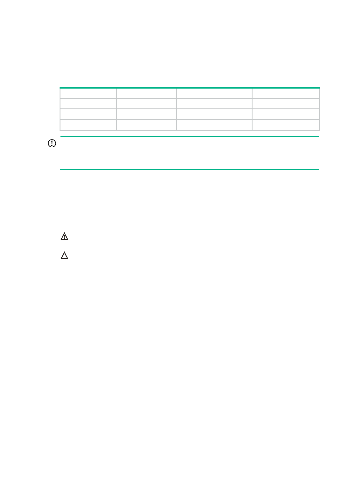
Table 3 Dust concentration limit in the equipment room
Substance Concentration limit (particles/m
Dust particles
NOTE:
Dust particle diameter ≥ 5 µm
The equipment room must also meet strict limits on salts, acids, and sulfides to eliminate corrosion
and premature aging of components, as shown in Tab l e 4 .
Table 4
Gas Max. (mg/m
SO2 0.2
H2S 0.006
NH
Cl
Harmful gas limits in the equipment room
3
2
≤ 3 x 10⁴
(No visible dust on desk in three days.)
3
)
0.05
0.01
3
)
Cooling system
The MSR2000 router adopts left to right airflow for heat dissipation.
2
Page 7
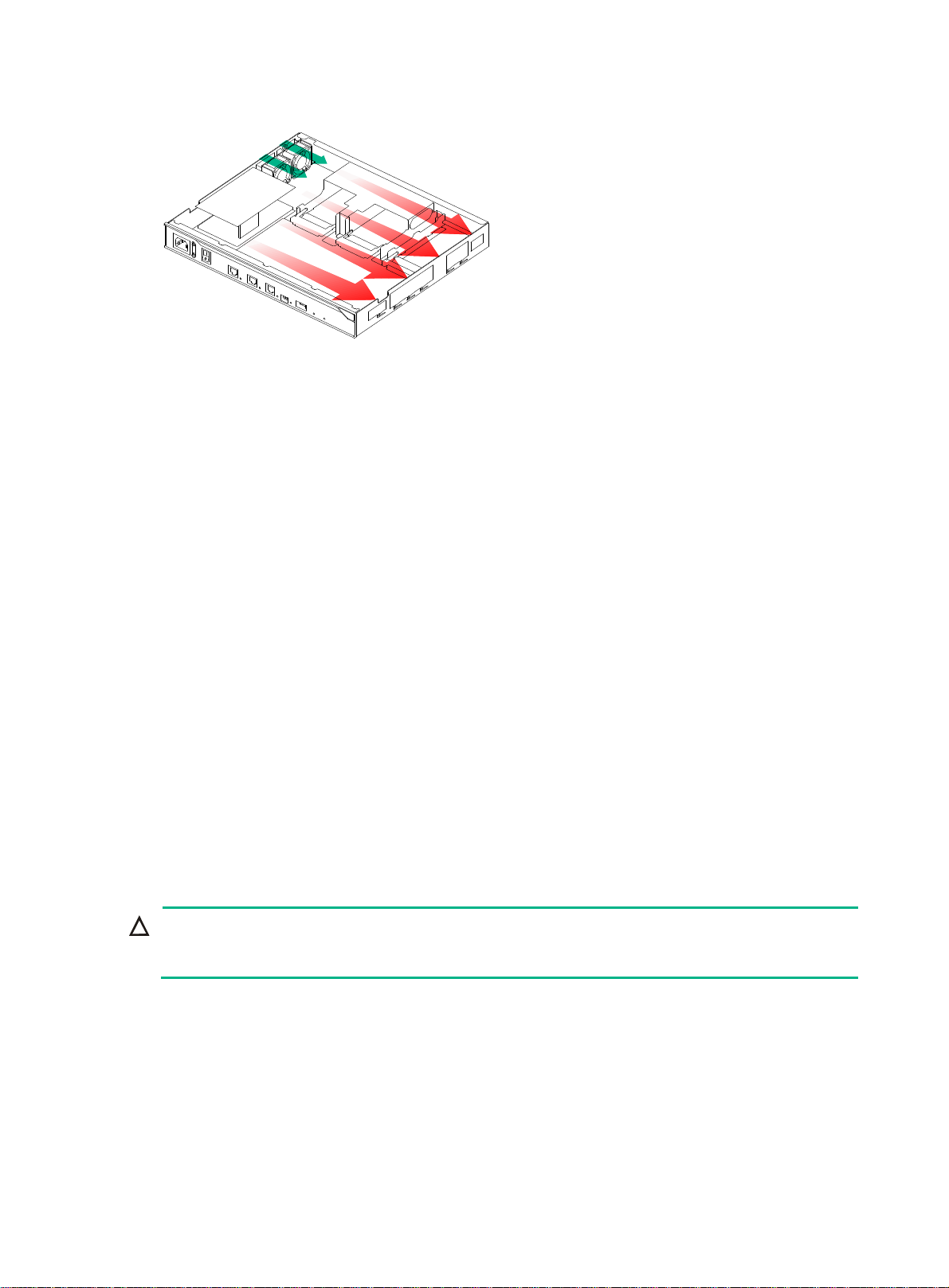
Figure 1 Airflow through the MSR2000 chassis
To ensure good ventilation, the following requirements must be met:
• The inlet and outlet air vents are not blocked, and leave at least 10 cm (3.94 in) of clearance.
• The installation site has a good cooling system.
ESD prevention
To prevent electrostatic discharge (ESD), follow these guidelines:
• Make sure the router and the floor are well grounded.
• Take dust-proof measures for the equipment room.
• Maintain the humidity and temperature at an acceptable level.
• Always wear an ESD wrist strap and ESD cloth when touching a circuit board or transceiver
module.
An MSR2000 router does not supply an ESD wrist wrap. Prepare an ESD wrist wrap yourself.
• Place the removed interface module on an antistatic workbench, with the face upward, or put it
into an antistatic bag.
• Touch only the edges, instead of electronic components when you observe or move a removed
interface module.
EMI
To attach an ESD wrist strap:
1. Wear the wrist strap on your wrist.
2. Lock the wrist strap tight around your wrist to keep good contact with the skin.
3. Insert the ESD plug into the ESD socket.
4. Make sure the rack is well grounded.
CAUTION:
Check the resistance of the ESD wrist strap for safety. The resistance reading should be in the range
of 1 to 10 megohm (Mohm) between human body and the ground.
All electromagnetic interference (EMI) sources, from outside or inside of the router and application
system, adversely affect the router in a conduction pattern of capacitance coupling, inductance
coupling, electromagnetic wave radiation, or common impedance (including grounding system)
coupling. To prevent EMI, follow these guidelines:
• Take measures against interference from the power grid.
3
Page 8

• Do not use the router together with the grounding equipment or lightning-prevention equipment
of power equipment, and keep the router far away from them.
• Keep the router far away from high-power radio launchers, radars, and equipment with high
frequency or high current.
• Use electromagnetic shielding when necessary.
Lightning protection
To better protect the MSR2000 router from lightning, do as follows:
• Make sure the grounding cable of the chassis is well grounded.
• Make sure the grounding terminal of the AC power receptacle is well grounded.
• Install a lightning arrester at the input end of the power supply to enhance the lightning
protection capability of the power supply.
• Install a special lightning arrester at the input end of outdoor signal lines (for example, E1/T1
line) to which interface modules of the router are connected to enhance the lightning protection
capability.
Rack-mounting
Before mounting the router in a rack, adhere to the following requirements:
• The rack is equipped with a good ventilation system.
• The rack is sturdy enough to support the router and its accessories.
• For heat dissipation and device maintenance, make sure the front and rear of the rack are at
least 0.8 m (2.62 ft) away from walls or other devices, and the headroom in the equipment room
is no less than 3 m (9.84 ft).
Installation accessories
4
Page 9

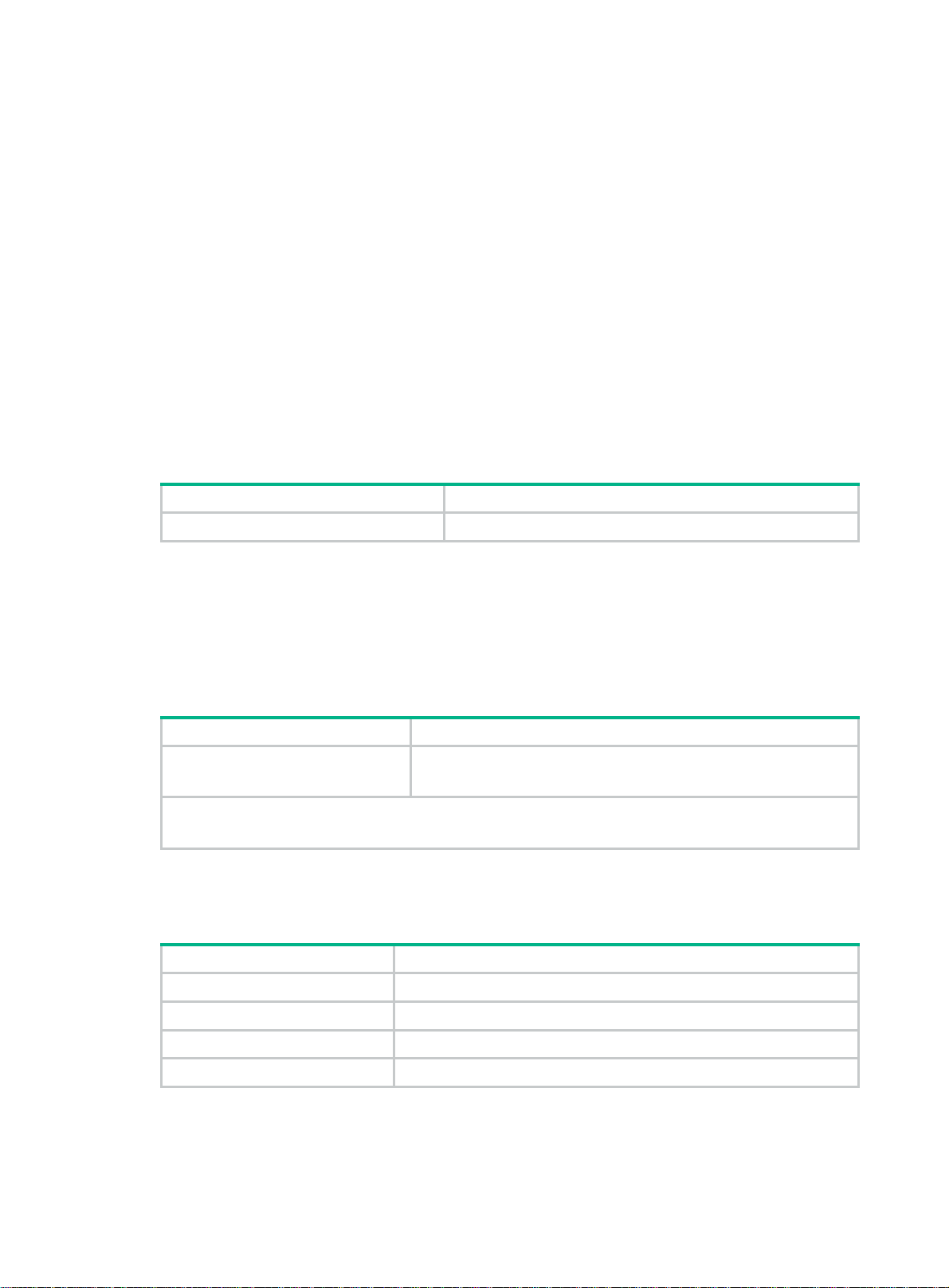
Pre-installation checklist
Table 5 Pre-installation checklist
Item Requirements Result
• There is a minimum clearance of 10 cm (3.94 in)
around the inlet and outlet air vents for heat
Ventilation
Temperature 0°C to 45°C (32°F to 113°F).
Relative humidity 5% to 90% (noncondensing).
Cleanness
ESD prevention
Installation
site
EMI prevention
Lightning protection
Electricity safety
Workbench
Rack-mounting
requirements
dissipation of the router chassis.
• A good ventilation system is available at the
installation site.
• Dust concentration ≤ 3 × 10
• No visible dust on desk within three days.
• The equipment and floor are well grounded.
• The equipment room is dust-proof.
• The humidity and temperature are at an acceptable
level.
• Wear an ESD wrist strap and uniform when touching
a circuit board.
• Place the removed interface module on an antistatic
workbench, with the face upward, or put it into an
antistatic bag.
• Touch only the edges, instead of electronic
components when observing or moving a removed
interface module.
• Take effective measures to protect the power system
from the power grid system.
• Separate the protection ground of the router from the
grounding device or lightning protection grounding
device as far as possible.
• Keep the router far away from radio stations, radar
and high-frequency devices working in high current.
• Use electromagnetic shielding when necessary.
• The grounding cable of the chassis is well grounded.
• The grounding terminal of the AC power receptacle is
well grounded.
• A port lightning arrester is installed. (Optional.)
• A power lightning arrester is installed. (Optional.)
• A signal lightning arrester is installed at the input end
of an external signal cable. (Optional.)
• Equip an uninterrupted power supply (UPS).
• In case of emergency during operation, switch off the
external power switch.
• The workbench is stable enough.
• The workbench is well grounded.
• The rack is equipped with a good ventilation system.
• The rack is sturdy enough to support the weight of
the router and installation accessories.
• The size of the rack is appropriate for the router.
• The front and rear of the rack are at least 0.8 m (2.62
ft) away from walls or other devices.
4
particles/m3.
5
Page 10

Item Requirements Result
Safety
precautions
Tools
Reference
• The router is far away from any moist area and heat source.
• The emergency power switch in the equipment room is located.
• Installation accessories supplied with the router.
• User supplied tools.
• Documents shipped with the router.
• Online documents.
6
Page 11

Installing the router
WARNING!
To avoid injury, do not touch bare wires, terminals, or parts with high-voltage hazard signs.
IMPORTANT:
• The barcode on the router chassis contains product information that must be provided to local
sales agent before you return a faulty router for service.
• Keep the tamper-proof seal on a mounting screw on the chassis cover intact, and if you want to
open the chassis, contact Hewlett Packard Enterprise for permission. Otherwise, Hewlett
Packard Enterprise shall not be liable for any consequence.
Installation prerequisites
• You have read "Preparing for installation" carefully.
• All requirements in "Preparing for installation" are met.
Installation flowchart
You can install the router on a workbench or on a rack. Select an installation method according to the
installation environment, and follow the installation flowchart shown in Figure 2.
7
Page 12

Figure 2 Installation flowchart
Start
Workbench
Mount to a workbench
Determine the
mounting location
Ground the router
Install interface modules
Connect the router to the
network
Connect the router to a
console terminal
Connect the power cord
Rack
Mount to a rack
Verify the installation
Power on the router Troubleshoot the router
Power off the routerOperating correctly?
No
Yes
End
8
Page 13

Installing the router
Mounting the router on a workbench
IMPORTANT:
• Ensure good ventilation and 10 cm (3.94 in) of clearance around the chassis for heat dissipation.
• Avoid placing heavy objects on the router.
To mount the router on a workbench:
1. Make sure the workbench is clean, stable, and correctly grounded.
2. Place the router upside down on the workbench and attach the rubber feet to the four round
holes in the chassis bottom.
Figure 3 Attaching the rubber feet
3. Place the router on the workbench with the upside up.
Figure 4 Mounting the router on a workbench
9
Page 14

Mounting the router to a rack
Rack-mounting clearance requirements
Figure 5 MSR2003 rack-mounting clearance requirement
60 mm
(2.36 in)
E1 cable
Mounting
bracket
Power cord
303.5 mm
(11.95 in)
60 mm (2.36 in)
10
Page 15

Figure 6 MSR2004-24 rack-mounting clearance requirement
11
Page 16

Figure 7 MSR2004-48 rack-mounting clearance requirement
Front mounting
bracket
Power cord
E1 cord
Ethernet
network cable
403.5 mm
(15.89 in)
60 mm
(2.36 in)
45 mm
(1.77 in)
Table 6 Rack-mounting clearance requirements
Model Router dimensions Requirements for the rack
• Height—44.2 mm (1.74 in) (1 RU)
MSR2003
MSR2004-24
• Width—360 mm (14.17 in)
• Total de pth—423.5 mm (16.67 in)
{ 303.5 mm (11.95 in) for the
chassis
{ 60 mm (2.36 in) for connecting an
AC power cord
{ 60 mm (2.36 in) for connecting an
E1 cable
• Height—44.2 mm (1.74 in), 1 RU
• Width—440 mm (17.32 in)
• Total de pth—483.5 mm (19.04 in)
{ 363.5 mm (14.31 in) for the
chassis
{ 60 mm (2.36 in) for connecting an
AC power cord
{ 60 mm (2.36 in) for connecting an
E1 cable
• Depth—A minimum of 0.5 m (1.64 ft)
• Distance from the front post to the
front door—A minimum of 80 mm
(3.15 in)
• Distance from the front post to the
rear door—A minimum of 370 mm
(14.57 in)
• Depth—A minimum of 0.6 m (1.97 ft)
• Distance from the front post to the
front door—A minimum of 80 mm
(3.15 in)
• Distance from the front post to the
rear door—A minimum of 420 mm
(16.54 in)
12
Page 17

Model Router dimensions Requirements for the rack
• Height—44.2 mm (1.74 in), 1 RU
• Width—440 mm (17.32 in)
• Total de pth—508.5 mm (20.02 in)
MSR2004-48
{ 403.5 mm (15.89 in) for the
{ 45 mm (1.77 in) for connecting an
{ 60 mm (2.36 in) for connecting an
Mounting the router to a rack
WARNING!
The mounting brackets can only support the weight of the router. To avoid damage to the router, do
not place any objects on the router.
1. Use a mounting bracket to mark the positions of cage nuts on the front rack posts, making sure
they are at the same level.
Figure 8 Marking the positions of cage nuts
chassis
Ethernet network cable
E1 cable
• Depth—A minimum of 0.6 m (1.97 ft)
• Distance from the front post to the
front door—A minimum of 80 mm
(3.15 in)
• Distance from the front post to the
rear door—A minimum of 460 mm
(18.11 in)
2. Insert one edge of a cage nut into the hole. Use a flat-blade screwdriver to compress the other
edge of the cage nut, and then push the cage nut fully into the hole.
13
Page 18

Figure 9 Installing cage nuts
3. Repeat step 3 to install other cage nuts to all the marked positions on the rack posts.
4. Attach the mounting brackets to the two sides of the chassis and fasten the screws..
Figure 10 Attaching the front mounting brackets
5. Place the chassis on the rack and use M6 screws to attach the mounting brackets to the rack
posts..
14
Page 19

Figure 11 Securing the router to the rack
Grounding the router
WARNING!
Correctly connecting the router grounding cable is crucial to lightning protection and EMI protection.
IMPORTANT:
The resistance reading should be smaller than 5 ohms between the chassis and the ground.
Grounding the router through the rack
IMPORTANT:
Make sure the rack is correctly grounded before grounding the router.
To connect the grounding cable:
1. Remove the two grounding screws from the rear panel of the chassis.
2. Attach the grounding screw to the ring terminal of the grounding cable. See Figure 12.
3. Use a Phillips screwdriver to fasten the g
4. Remove the grounding screw from the grounding point on the rack.
5. Use a needle-nose pliers to bend a hook at the other end of the grounding cable, attach it to the
grounding point, and secure it with a screw. See Figure 13.
rounding screw into the grounding screw hole.
15
Page 20

Figure 12 Connecting the grounding cable to the grounding hole of the router
Figure 13 Grounding the router through the rack (1)
16
Page 21

Figure 14 Grounding the router through the rack (2)
Grounding the router with a grounding strip
If a grounding strip is available at the installation site, connect the grounding cable to the grounding
strip.
Follow the same procedures in "Grounding the router through the rack" to conne
cable.
ct the grounding
17
Page 22

Figure 15 Grounding the router with a grounding strip
Grounding the router with a grounding conductor buried in the earth ground
If the installation site has no grounding strips, but earth ground is available, hammer a 0.5 m (1.64 ft)
or longer angle iron or steel tube into the earth ground to serve as a grounding conductor. The steel
tube must be zinc-coated. Weld the yellow-green grounding cable to the angel iron or steel tube and
treat the joint for corrosion protection.
Installing an interface module
Installing a SIC
CAUTION:
SICs are not hot swappable. Make sure the router is powered off before installing a SIC.
To install a SIC:
1. Remove the fastening screws with a Phillips screwdriver to remove the filler panel.
Keep the removed filler panel for future use.
2. Push the SIC slowly along the slide rails into the slot until it makes close contact with the
backplane of the router.
3. Use a Phillips screwdriver to fasten the captive screws on the SIC.
18
Page 23

Figure 16 Removing the filler panel
Figure 17 Installing a SIC
Installing a DSIC
CAUTION:
DSICs are not hot swappable. Make sure the router is powered off before installing a DSIC.
The MSR2004 router does not support DSICs.
To install a DSIC:
1. Remove the screws on the filler panel on slot 1 and slot 2 of the router to remove the filler panel.
Figure 18 Removing the filler panel
2. Loosen the captive screws on the slot divider and pull out the slot divider.
19
Page 24

Figure 19 Removing the slot divider
3. Insert the DSIC into the slot and push it along the slide rails until it makes close contact with the
backplane of the router.
Figure 20 Installing a DSIC
4. Fasten the captive screws to secure the DSIC.
Connecting the router to the network
Connect the router to the network before powering on the router. This section describes how to
connect the router to the network through Ethernet cables. For other connection methods, see HPE
MSR Router Series Interface Module Guide.
To connect an Ethernet cable:
1. Plug one end of an Ethernet twisted pair cable into the copper Ethernet port (RJ-45 port) to be
connected on the router.
2. Plug the other end of the cable into the RJ-45 port of the peer device.
20
Page 25

Figure 21 Connecting the router to a PC
Logging in to the router
At the first login, you can access an MSR2003 router through the console port by using a console
cable or through the USB console port by using a USB cable. You can only access an MSR2004
router through the console port by using a console cable.
Connecting a console cable
IMPORTANT:
When you connect a PC to a powered-on router, connect the RJ-45 connector to the router after
connecting the DB-9 connector of the console cable to the PC.
To connect a console cable:
1. Plug the DB-9 female connector to the serial port of the configuration terminal.
2. Connect the RJ-45 connector to the console port of the router.
Figure 22 Connecting a console cable
21
Page 26

Connecting a USB cable
IMPORTANT:
Download and install the USB console driver program before configuring the device when you
connect the device through a USB console cable.
To connect a USB cable:
1. Connect the USB port to the PC.
2. Connect the other end to the USB console port of the router.
Figure 23 Connecting a USB cable
3. Click the following link, or copy it to the address bar on the browser to log in to download page
of the USB console driver, and download the driver.
http://www.exar.com/connectivity/uart-and-br
idging-solutions/usb-uarts/xr21v1410
4. Select a driver program according to the operating system you use:
{ XR21V1410_XR21B1411_Windows_Ver1840_x86_Installer.EXE—Applicable to 32-bit
operating systems.
{ XR21V1410_XR21B1411_Windows_Ver1840_x64_Installer.EXE—Applicable to 32-bit
operating systems.
5. Click Next on the installation wizard.
22
 Loading...