

Page 1

HP MSR20-1X Router Series
Installation Guide
Part number: 5998-1410
Document version: 6PW101-20140523
Page 2

Legal and notice information
© Copyright 2014 Hewlett-Packard Development Company, L.P.
No part of this documentation may be reproduced or transmitted in any form or by any means without
prior written consent of Hewlett-Packard Development Company, L.P.
The information contained herein is subject to change without notice.
HEWLETT-PACKARD COMPANY MAKES NO WARRANTY OF ANY KIND WITH REGARD TO THIS
MATERIAL, INCLUDING, BUT NOT LIMITED TO, THE IMPLIED WARRANTIES OF MERCHANTABILITY
AND FITNESS FOR A PARTICULAR PURPOSE. Hewlett-Packard shall not be liable for errors contained
herein or for incidental or consequential damages in connection with the furnishing, performance, or
use of this material.
The only warranties for HP products and services are set forth in the express warranty statements
accompanying such products and services. Nothing herein should be construed as constituting an
additional warranty. HP shall not be liable for technical or editorial errors or omissions contained
herein.
Page 3

Contents
Product overview ·························································································································································· 1
MSR20-10 panel views ···················································································································································· 1
MSR20-11 panel views ···················································································································································· 2
MSR20-12 panel views ···················································································································································· 3
MSR20-12-W panel views ··············································································································································· 3
MSR20-12-T panel views ················································································································································· 4
MSR20-12-T-W(NA) panel views ···································································································································· 5
MSR20-13 panel views ···················································································································································· 5
MSR20-13-W panel views ··············································································································································· 6
MSR20-13-W(NA) panel views ······································································································································· 7
Preparing for installation ············································································································································· 8
Safety recommendations ·················································································································································· 8
Safety symbols ·························································································································································· 8
General safety recommendations ··························································································································· 8
Safety with electricity ··············································································································································· 8
Examining the installation site ········································································································································· 8
Temperature and humidity ······································································································································· 9
Cleanness ·································································································································································· 9
Cooling system ························································································································································· 9
ESD prevention ······················································································································································ 10
EMI ·········································································································································································· 10
Lightning protection ··············································································································································· 11
Rack-mounting ························································································································································ 11
Installation tools ······························································································································································ 11
Checklist before installation ·········································································································································· 12
Installing the router ····················································································································································· 14
Check before installation ··············································································································································· 14
Installation flow ······························································································································································ 14
Installing the router ························································································································································· 15
Installing the router to a workbench ···················································································································· 15
Installing the router on a wall ······························································································································· 16
Installing the router to a 19-inch rack ················································································································· 17
Grounding the router ············································································································································ 18
Installing an antenna ············································································································································· 20
Installing interface modules ·································································································································· 21
Connecting interface cables ································································································································· 22
Connecting the console cable and setting terminal parameters ······································································ 26
Connecting an AC power cord ··························································································································· 29
Verifying the installation ······································································································································· 29
Starting up and configuring the router ························································································································· 30
Powering on the router ········································································································································· 30
Configuring basic settings for the router ············································································································· 31
Installing and upgrading internal modules ··············································································································· 32
Locating the internal modules in the router ·················································································································· 32
Opening and removing the chassis cover ·········································································································· 32
Locating the internal modules in the router ········································································································· 33
Installing and removing a VPM module ······················································································································· 34
i
Page 4

Installing a VPM module ······································································································································· 34
Removing a VPM module ····································································································································· 34
Troubleshooting ·························································································································································· 36
Power supply failures ····················································································································································· 36
Power LED is off ····················································································································································· 36
Configuration system problems ···································································································································· 36
No terminal display ·············································································································································· 36
Garbled terminal display ······································································································································ 37
No response from the serial port ························································································································· 37
Password loss ································································································································································· 37
User password loss ··············································································································································· 37
Super password loss ············································································································································· 38
Interface module, cable, and connection failure ········································································································ 38
Appendix A Technical specifications ························································································································ 40
MSR20-1X specifications ··············································································································································· 40
Antenna specifications ··················································································································································· 41
Appendix B LEDs and Reset button ··························································································································· 42
LEDs ················································································································································································· 42
MSR20-10 ······························································································································································ 42
MSR20-11 ······························································································································································ 42
MSR20-12 ······························································································································································ 43
MSR20-12-W ························································································································································· 44
MSR20-12-T ··························································································································································· 45
MSR20-12-T-W(NA) ·············································································································································· 45
MSR20-13 ······························································································································································ 46
MSR20-13-W/MSR20-13-W(NA) ······················································································································· 47
Reset button ····································································································································································· 48
Appendix C Setting the fixed E1 port impedance ··································································································· 49
Appendix D Arranging slots and numbering interfaces ···························································································· 1
Slot arrangement ······························································································································································· 1
Numbering interfaces ······················································································································································· 1
Index ············································································································································································· 1
ii
Page 5
Product overview
#
ype
The HP MSR20-1x Router Series includes the following models:
J
T
JD431A MSR20-10
JF239A MSR20-11
JF241A MSR20-12
JF807A MSR20-12-W
JF806A MSR20-12-T
JG209A MSR20-12-T-W(NA)
JF240A MSR20-13
JF808A MSR20-13-W
JG210A MSR20-13-W(NA)
This chapter describes the chassis panel views of these routers.
NOTE:
The chassis panel views in this document are for illustration only and might slightly differ from the actual
panel views.
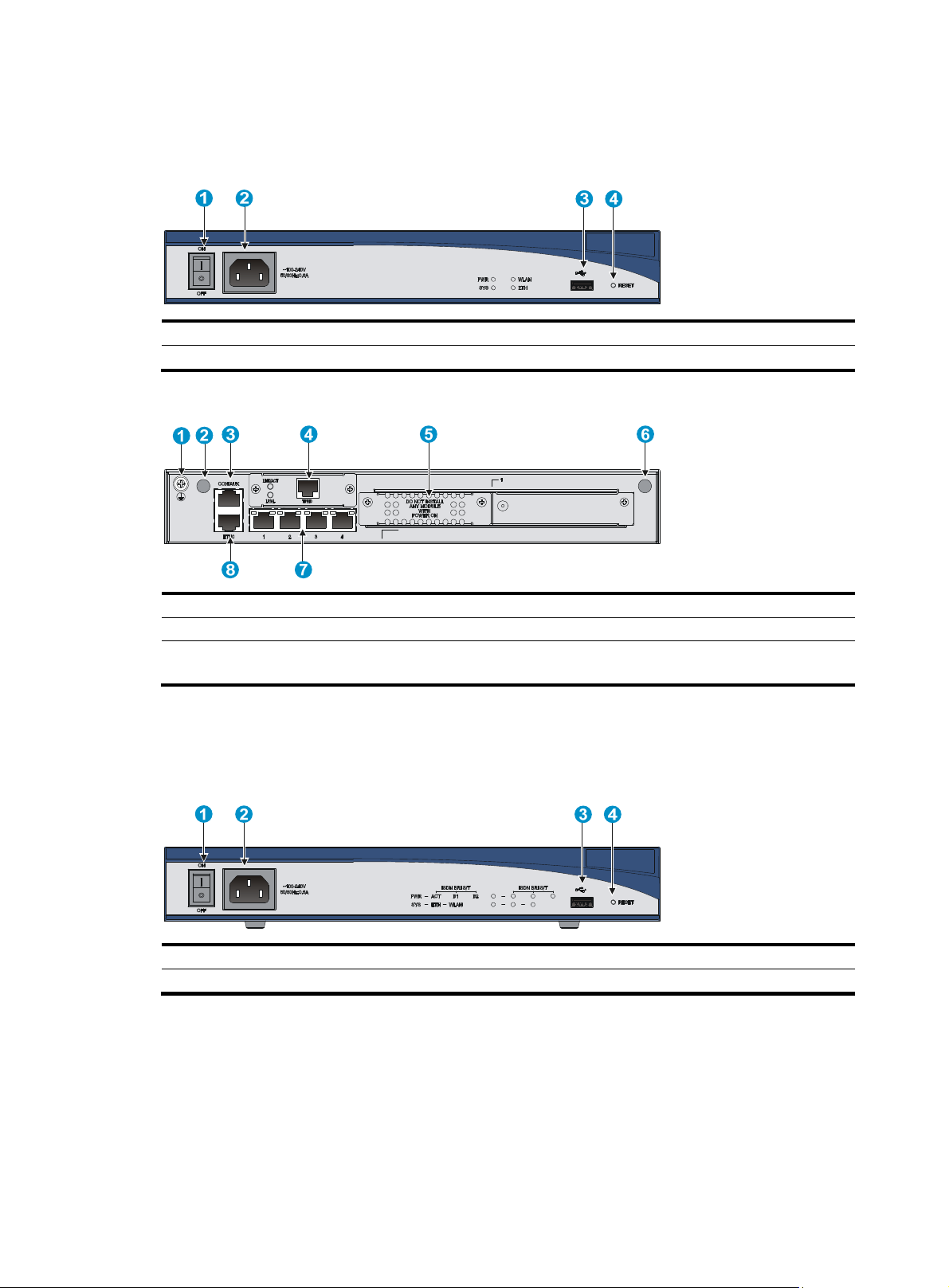
MSR20-10 panel views
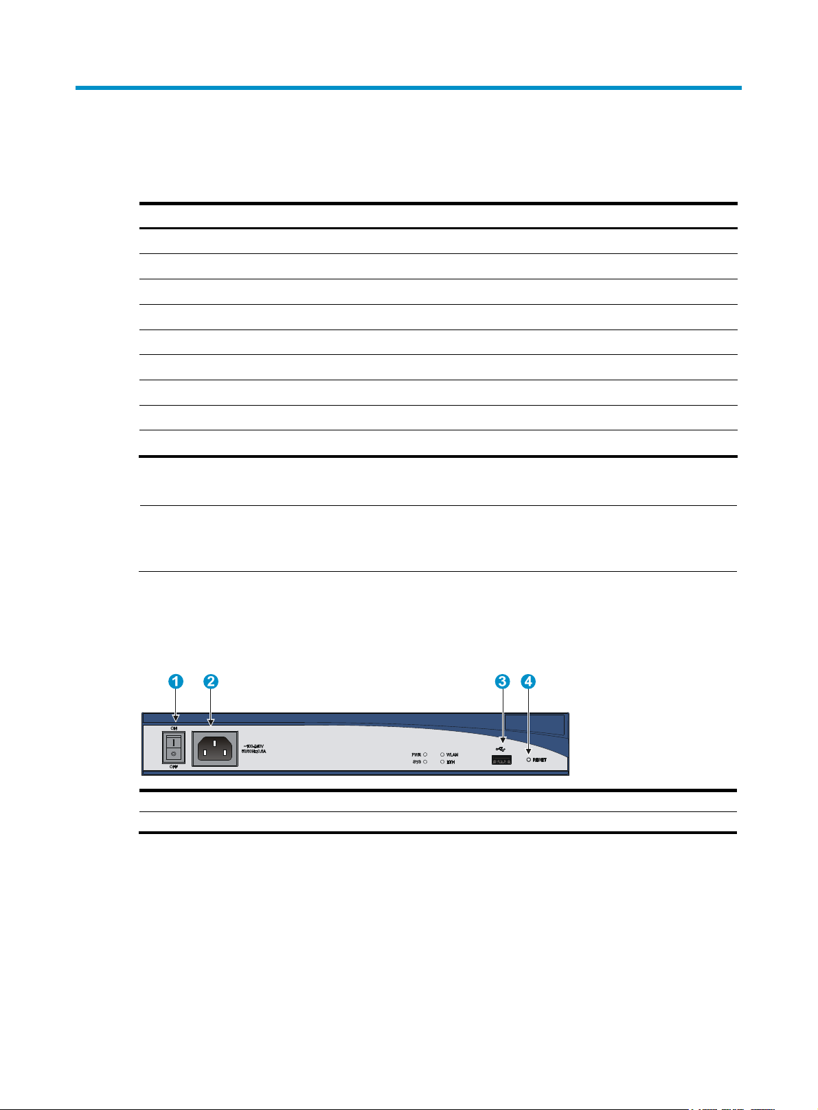
Figure 1 MSR20-10 front panel
(1) Power switch (2) Power receptacle
(4) Reset button
(3) USB port
1
Page 6
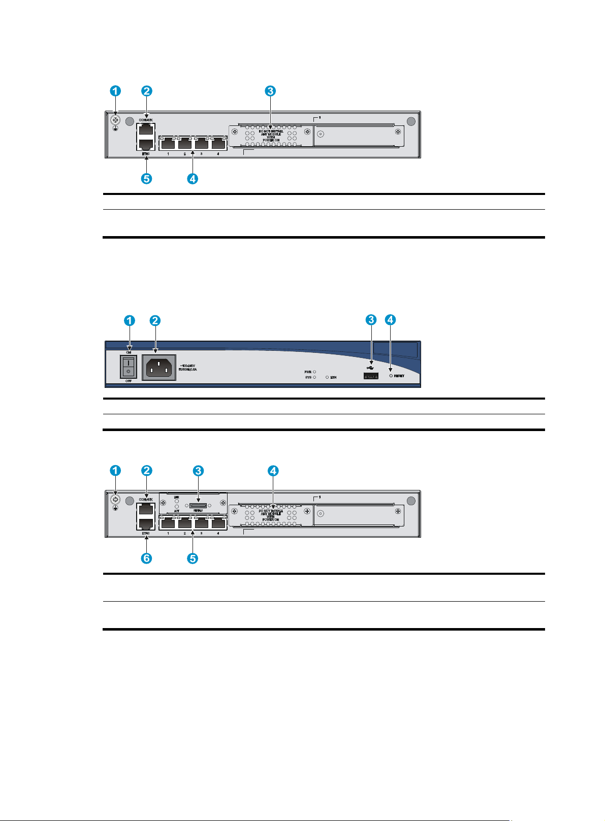
Figure 2 MSR20-10 rear panel
(1) Grounding screw (2) Console/AUX port
(4) Ethernet LAN ports (ETH1 to
ETH4)
(5) Ethernet WAN port ETH0
MSR20-11 panel views
Figure 3 MSR20-11 front panel
(1) Power switch (2) Power receptacle
(4) Reset button
Figure 4 MSR20-11 rear panel
(3) SIC/DSIC slot
(3) USB port
(1) Grounding screw (2) Console/AUX port (3) Synchronous/asynchronous
serial
port Serial 0
(4) SIC/DSIC slot (5) Ethernet LAN ports (ETH1 to
ETH4)
2
(6) Ethernet WAN port ETH0
Page 7
MSR20-12 panel views
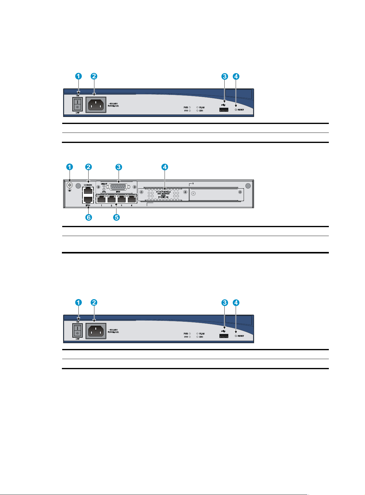
Figure 5 MSR20-12 front panel
(1) Power switch (2) Power receptacle
(4) Reset button
Figure 6 MSR20-12 rear panel
(1) Grounding screw (2) Console/AUX port
(4) SIC/DSIC slot (5) Ethernet LAN ports (ETH1 to
ETH4)
MSR20-12-W panel views
Figure 7 MSR20-12-W front panel
(3) USB port
(3) E1 port EPRI0
(6) Ethernet WAN port ETH0
(1) Power switch (2) Power receptacle
(4) Reset button
3
(3) USB port
Page 8
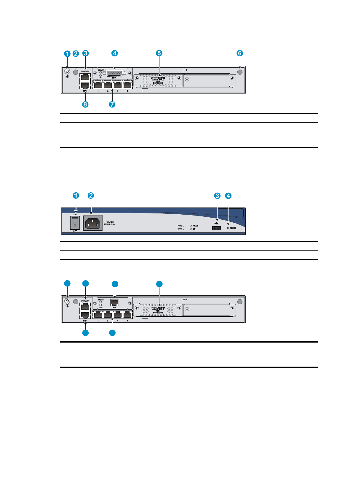
Figure 8 MSR20-12-W rear panel
(1) Grounding screw (2) Antenna port
(4) E1 port EPRI0 (5) SIC/DSIC slot
(7) Ethernet LAN ports (ETH1 to
ETH4)
(8) Ethernet WAN port ETH0
MSR20-12-T panel views
Figure 9 MSR20-12-T front panel
(1) Power switch (2) Power receptacle (3) USB port
(4) Reset button
Figure 10 MSR20-12-T rear panel
1 2
3
4
(3) Console/AUX port
(6) Antenna port
56
(1) Grounding screw (2) Console/AUX port (3) T1 port TPRI0
(4) SIC/DSIC slot (5) Ethernet LAN ports (ETH1 to
ETH4)
4
(6) Ethernet WAN port ETH0
Page 9
MSR20-12-T-W(NA) panel views
Figure 11 MSR20-12-T-W(NA) front panel
(1) Power switch (2) Power receptacle
(4) Reset button
Figure 12 MSR20-12-T-W(NA) rear panel
(1) Grounding screw (2) Antenna port
(4) T1 port TPRI0 (5) SIC/DSIC slot
(7) Ethernet LAN ports (ETH1 to
ETH4)
(8) Ethernet WAN port ETH0
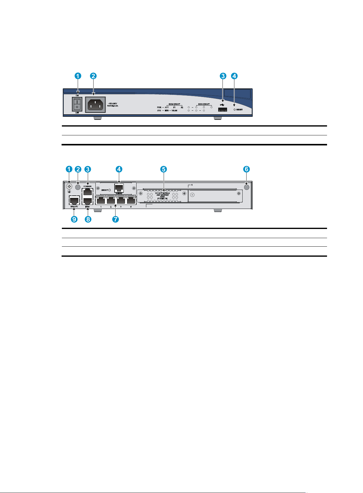
MSR20-13 panel views
Figure 13 MSR20-13 front panel
(3) USB port
(3) Console/AUX port
(6) Antenna port
(1) Power switch (2) Power receptacle (3) USB port
(4) Reset button
5
Page 10
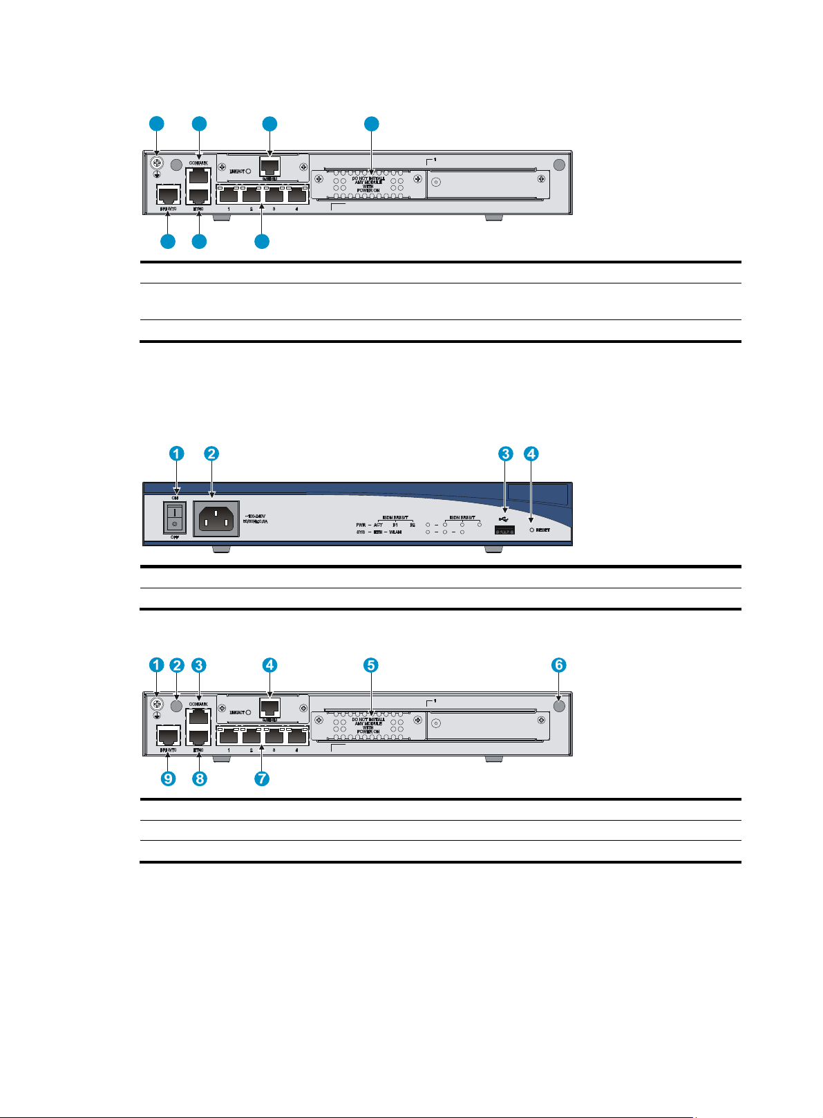
Figure 14 MSR20-13 rear panel
1 2
3 4
567
(1) Grounding screw (2) Console/AUX port
(4) SIC/DSIC slot (5) Ethernet LAN ports (ETH1 to
ETH4)
(7) ISDN BRI S/T0 port
MSR20-13-W panel views
Figure 15 MSR20-13-W front panel
(3) G.SHDSL0 port
(6) Ethernet WAN port ETH0
(1) Power switch (2) Power receptacle
(4) Reset button
(3) USB port
Figure 16 MSR20-13-W rear panel
(1) Grounding screw (2) Antenna port
(4) G.SHDSL0 port
(7) Ethernet LAN ports (ETH1 to ETH4) (8) Ethernet WAN port ETH0 (9) ISDN BRI S/T0 port
(5) SIC/DSIC slot
(3) Console/AUX port
(6) Antenna port
6
Page 11
MSR20-13-W(NA) panel views
Figure 17 MSR20-13-W(NA) front panel
(1) Power switch (2) Power receptacle (3) USB port
(4) Reset button
Figure 18 MSR20-13-W rear panel
(1) Grounding screw (2) Antenna port (3) Console/AUX port
(4) G.SHDSL0 port
(7) Ethernet LAN ports (ETH1 to ETH4) (8) Ethernet WAN port ETH0
(5) SIC/DSIC slot
(6) Antenna port
(9) ISDN BRI S/T0 port
7
Page 12

Preparing for installation
Safety recommendations
Safety symbols
When reading this document, note the following symbols:
WARNING means an alert that calls attention to important information that if not understood or
followed can result in personal injury.
CAUTION means an alert that calls attention to important information that if not understood or
followed can result in data loss, data corruption, or damage to hardware or software.
General safety recommendations
• Keep the chassis and installation tools away from walk areas.
• Make sure that the ground is dry and flat and anti-slip measures are in place.
• Unplug all the external cables (including power cables) before moving the chassis.
Safety with electricity
• Locate the emergency power-off switch in the room before installation. Shut the power off at once in
case accident occurs.
• Make sure that the router has been correctly grounded.
• Do not open or close the chassis cover when the router is powered on.
• Connect the interface cables for the router correctly.
• Use an uninterrupted power supply (UPS).
• If there are two power inputs, disconnect the two power inputs to power off the router.
• Do not work alone when the router has power.
• Always check that the power has been disconnected.
Examining the installation site
The HP MSR20-1X router can only be used indoors. To ensure that the router works properly and to
prolong its service lifetime, the installation site must meet the following requirements:
• Temperature and humidity
• Cleanness
• Cooling system
• ESD prevention
• EMI
• Lightning protection
8
Page 13

• Rack-mounting
p
y
p
g
Temperature and humidity
You must maintain a proper temperature and humidity in the equipment room. Long-term high humidity
may lead to bad insulation, electricity leakage, mechanical property changes, and metal corrosion.
However, if the relative humidity is too low, captive screws may become loose as the result of contraction
of insulation washers and static electricity may be produced in a dry environment to jeopardize the
circuits on the device. A high temperature is the most undesirable condition, because it accelerates the
aging of insulation materials and significantly lowers reliability and service life of the router.
For the temperature and humidity requirements of the router, see Table 1.
Table 1 Temperature/humidity requirements
Tem
erature Relative humidit
0°C to 40°C (32°F to 104°F) 5% to 90%
Cleanness
Dust buildup on the chassis may result in electrostatic adsorption, which causes poor contact of metal
components and contact points, especially when indoor relative humidity is low. In the worst case,
electrostatic adsorption can cause communication failure.
Table 2 Dust concentration limit in the equipment room
Substance Concentration limit (
Dust particles
NOTE:
Dust particle diameter ≥ 5 μm
≤ 3 x 10⁴
(No visible dust on desk in three days)
articles/cu m)
The equipment room must also meet strict limits on salts, acids, and sulfides to eliminate corrosion and
premature aging of components, as shown in Table 3.
Table 3 Harmful gas limits in an equipment room
Gas Max. (m
SO2 0.2
H2S 0.006
NH
3
Cl
2
0.05
0.01
/m3)
Cooling system
• Make sure there is enough space (greater than 10 cm (3.94 in)) around the air intake and outlet
vents on the router for good ventilation.
• Make sure the installation site has a good cooling system.
9
Page 14

ESD prevention
g
To prevent electrostatic discharge (ESD), note the following guidelines:
• Make sure that the router and the floor are well grounded.
• Take dust-proof measures for the equipment room.
• Maintain the humidity and temperature at a proper level.
• Always wear an ESD-preventive wrist strap when touching a circuit board or transceiver module.
To use the ESD-preventive wrist strap:
1. Wear the wrist strap on your wrist.
2. Lock the wrist strap tight around your wrist to keep good contact with the skin.
3. Insert the ESD-preventive wrist strap into the specially designed hole on the router chassis or attach
it to the grounding screw of the chassis with the alligator clips.
4. Make sure that the rack is well grounded.
Figure 19 Use an ESD-preventive wrist strap
EMI
(1) ESD-preventive wrist strap (2) Lock (3) Alligator clip
CAUTION:
• Check the resistance of the ESD-preventive wrist strap for safety. The resistance readin
should be in the
range of 1 to 10 megohm (Mohm) between human body and the ground.
• No ESD-preventive wrist strap is provided with the HP MSR20-1X router. Prepare it yourself.
All electromagnetic interference (EMI) sources, from outside or inside of the router and application system,
adversely affect the router in a conduction pattern of capacitance coupling, inductance coupling,
electromagnetic wave radiation, or common impedance (including grounding system) coupling. To
prevent EMI, perform the following steps:
• Take measures against interference from the power grid.
• Do not use the router together with the grounding equipment or light-prevention equipment of
power equipment, and keep the router far away from them.
• Keep the router far away from high-power radio launchers, radars, and equipment with high
frequency or high current.
10
Page 15

NOTE:
Use electromagnetic shielding when necessary.
Lightning protection
To protect the router from lightning better, do as follows:
• Make sure the grounding cable of the chassis is well grounded.
• Make sure the grounding terminal of the AC power receptacle is well grounded.
• Install a lightning arrester at the input end of the power supply to enhance the lightning protection
capability of the power supply.
• Install a special lightning arrester at the input end of outdoor signal lines (for example, E1/T1 line)
to which interface modules of the router are connected to enhance the lightning protection
capability.
Rack-mounting
Before mounting the router in a standard 19-inch rack, adhere to the following requirements:
• The rack has a good ventilation system.
• The rack is sturdy enough to support the router and installation accessories.
• Make sure that the size of the rack is appropriate for the router, and that there is enough clearance
around the left and right sides of the router for heat dissipation.
• For heat dissipation and device maintenance, make sure the front and rear of the rack should be at
least 0.8 m (2.62 ft) away from walls or other devices, and that the headroom in the equipment
room should be no less than 3 m (9.84 ft).
Installation tools
Accessories supplied by the router
• Power cable
• Console cable
• Grounding cable
User-supplied tools and equipment
• Cross-head screwdriver P1 – 100 mm, P2 – 150 mm and P3 – 250 mm
• Plain screwdriver P4 – 75 mm
• Screws with different specifications
• Meters and equipment such as HUB, terminal, and multimeter
• ESD-preventive gloves, ESD-preventive wrist strap, ESD-preventive bag or mat
• Electric drill
• Hammer
11
Page 16

Checklist before installation
q
Table 4 Checklist before installation
Item Re
• There is a minimum clearance of 10 cm (3.9 in) around the
Ventilation
• A ventilation system is available at the installation site.
Temperature 0°C to 40°C (32°F to 104°F)
Relative humidity 5% to 90% (noncondensing)
Cleanness Dust concentration ≤ 3 × 10⁴ particles/m3
• The equipment and floor are well grounded.
• The equipment room is dust-proof.
ESD prevention
• The humidity and temperature are at a proper level,
• Wear an ESD-preventive wrist strap and uniform when
• Take effective measures to protect the power system from
• Separate the protection ground of the router from the
EMI prevention
• Keep the router far away from radio stations, radar and
Installation
site
• Use electromagnetic shielding when necessary.
• The grounding cable of the chassis is well grounded.
• The grounding terminal of the AC power receptacle is well
Lightning protection
• A port lightning arrester is installed. (Optional)
• A power lightning arrester is installed. (Optional)
• A signal lightning arrester is installed at the input end of
• Equip an uninterrupted power supply (UPS).
Electricity safety
Workbench
• In case of emergency during operation, switch off the
• The workbench is stable enough
• Well grounding
• Install the router in an open rack if possible. If you install
Rack-mounting
requirements
• The rack is sturdy enough to support the weight of the
• The size of the cabinet is appropriate for the router.
• The front and rear of the cabinet are at least 0.8 m (31.50
uirements
inlet and exhaust vents for heat dissipation of the router
chassis.
respectively.
touching a circuit board.
the power grid system.
grounding device or lightning protection grounding
device as far as possible.
high-frequency devices working in high current.
grounded.
an external signal cable. (Optional)
external power switch.
the router in a closed cabinet, make sure that the cabinet is
equipped with a good ventilation system.
router and installation accessories.
in) away from walls or other devices.
Result
12
Page 17

Item Requirements
Safety
precautions
Tools
Reference
• The router is far away from any moist area and heat source.
• The emergency power switch in the equipment room is located.
• Installation accessories supplied with the router
• User supplied tools
• Documents shipped with the router
• Online documents
Result
13
Page 18

W
g
g
g
g
g
Installing the router
ARNING!
To avoid bodily injury, do not touch any naked wires and terminals, and parts with a high-volta
sign.
NOTE:
e hazard
• The barcode stuck on the router chassis contains information about production and servicin
return a faulty router for servin
agent.
• An HP tamper-proof label is stuck on a mounting screw on the router chassis. The local sales agent
requires intactness of the tamper-proof label when maintaining the router. Therefore, before you open
the chassis cover, please contact your local sales a
provided by the a
failure occurs.
ent; otherwise, the user takes full responsibility for own operation if any maintenance
, please provide the barcode information of the router to your local sales
Check before installation
• You have read through the chapter “Preparing for installation” carefully.
• All requirements in the chapter “Preparing for installation” are satisfied.
Installation flow
You can select one of the following installation methods, and follow the installation procedures shown
in Figure 20 to install your router.
• Install the router to a workbench
• Install the router to a wall
. Before you
ent to ask for permission or follow the instruction as
• Install the router to a 19-inch rack
14
Page 19

Figure 20 MSR20-1X router installation flow
Start
Install the router to a
workbench
Check the workbench Install a 19-inch rack
Install the router to a
specified position?
Install the router to a wall
Install wall-mounting screws
Ground the router
Install antennas
Install interface modules
Connect interface cables
Connect the router to a
console terminal
Connect the power cord
Install the router to a rack
Verify the installation
Power on the router
Operating properly? Power off the router
Yes
End
Installing the router
Installing the router to a workbench
You can install the MSR20-1X router to a clean workbench. When installing the router, follow these
guidelines:
• Make sure that the workbench is stable and well grounded.
• Reserve a space of 10 cm (3.9 in) around the router for heat dissipation.
Troubleshoot the router
No
• Do not place heavy objects on the router.
15
Page 20

To install the router to a workbench:
1. Place the router up-side down on the workbench, and attach the rubber feet to the four round holes
in the chassis bottom.
2. Place the router top-side up on the workbench.
Figure 21 Install the router to a workbench
Installing the router on a wall
To install the router to a wall:
1. Mark the locations of the two mounting holes on the wall.
2. Drill two holes in the wall.
Drill each hole at least 22 mm (0.87 in) deep, and make sure the two holes are on the same
horizontal line and 170 mm (6.69 in) apart.
3. Insert an anchor into each hole until it is all flush with the wall surface.
4. Drive the screws into the anchors, keeping the screws at least 1.5 mm (0.06 in) outside the wall.
5. Hang the router on the screws.
16
Page 21

W
v
g
g
Figure 22 Wall-mounting
CAUTION:
hen mounting the router, keep the network interface facing downwards and the two sides with
entilation holes vertical to the ground.
Installing the router to a 19-inch rack
NOTE:
The MSR20-1X router does not provide mountin
brackets.
brackets. To install the router to a rack, order mountin
17
Page 22

W
g
W
To install the router to a 19-inch rack:
1. Determine where to install the cage nuts according to the hole distances of the mounting brackets.
2. Install cage nuts to the rack posts.
3. Attach the front left and right mounting brackets to the router.
4. Fix the router horizontally by fastening the mounting brackets to the rack with appropriate pan
head screws. The specifications of pan head screws must satisfy the installation requirements, and
rustproof treatment has been made to their surfaces.
Figure 23 MSR20-1X mounting brackets
(1) Left front mounting bracket (2) Right front mounting bracket
Figure 24 Fix the router to the rack
21
3 4
ARNING!
Mounting brackets support only the weight of the router. To avoid dama
e to the router, do not place any
objects on the router.
Grounding the router
ARNING!
• Correctly connecting the router grounding cable is crucial to lightning protection and EMI protection.
• The grounding resistance should be less than 5 ohms. If the router is installed in a 19-inch standard rack,
the rack must also be well grounded.
18
Page 23

You can ground the router in one of the following ways, depending on the grounding conditions
available at the installation site:
• Grounding the router with a grounding strip
• Grounding the router with a grounding conductor buried in the earth ground
Grounding the router with a grounding strip
To connect the grounding cable:
1. Remove the grounding screw from the rear panel of the router chassis.
2. Put the supplied OT terminal of the grounding cable on the grounding screw.
3. Fasten the grounding screw, which is attached with the OT terminal of the grounding cable, into
the grounding screw hole with a screwdriver.
4. Attach the other end of the grounding cable to the grounding strip or grounding hole in the chassis.
Figure 25 Protection grounding terminal of the router
(1) Grounding screw (2) OT terminal
(3) Grounding hole
(4) Grounding cable
Figure 26 Connect the grounding cable to a grounding strip
(1) Hex nut (2) Grounding cable
(3) Naked metal part (4) Grounding post
(5) Grounding strip
19
Page 24

Figure 27 Connect the grounding cable to the chassis
(1) OT terminal
Grounding the router with a grounding conductor buried in the earth ground
If the installation site has no grounding strips, but earth ground is available, hammer a 0.5 m (1.64 ft) or
longer angle iron or steel tube into the earth ground to serve as a grounding conductor.
Figure 28 Ground the switch by burying the grounding conductor into the earth ground
(1) Earth (2) Joint
(3) Angle iron
Installing an antenna
To install an antenna:
1. Adjust the angle of the antenna to 180º.
2. Fasten the antenna onto the router.
Avoid over-tightening. The antenna must be vertical to the ground or ceiling to achieve the optimal
coverage.
20
Page 25

Figure 29 Install an antenna
CAUTION:
• Do not touch the antenna top, especially after the antenna is connected with the grounding contact.
Otherwise electrostatic discharge (ESD) may damage the router.
• To ensure signal quality, use antennae supplied with the router.
Installing interface modules
Installing a SIC interface module
CAUTION:
Before installing an interface module, make sure the router is powered off. If not, power off the router.
To install a SIC interface module:
1. Remove the screws of the filler panel by using a Phillips screwdriver, and then remove the filler
panel.
2. Push the SIC interface module into the SIC slot along the slide rails until it closely mates with the
rear panel of the router.
3. Use a flat-blade screwdriver to fasten the captive screws to fix the SIC interface module to the
router.
Figure 30 Install the SIC interface module
Installing a DSIC interface module
CAUTION:
Before installing an interface module, make sure the router is powered off. If not, power off the router.
21
Page 26

To install a DSIC interface module:
1. Remove the screws on the two horizontal neighboring SIC filler panels and the slot divider by using
a Phillips screwdriver.
2. Draw out the slot divider.
3. Push the DSIC interface module into the DSIC slot along the guide rails until it closely mates with the
rear panel of the router.
4. Use a flat-blade screwdriver to fasten the captive screws to fix the DSIC interface module to the
router.
Figure 31 Install a DSIC interface module
1 2
3 4
5
Connecting interface cables
Before powering on the router, connect the interface cables of the router.
Connecting an Ethernet cable
To connect a copper Ethernet port, connect one end of the E thern et c able t o an E ther net p ort o n the route r
and the other end to the peer device. For a 10/100 Mbps copper Ethernet port that supports MDI/MDIX
autosensing, use a straight-through cable or crossover cable to connect the port to a hub or LAN switch.
Figure 32 Connect an Ethernet cable to a WAN port
22
Page 27

Figure 33 Connect an Ethernet cable to a LAN port
Connecting a synchronous/asynchronous serial interface cable
The MSR20-11 uses a synchronous/asynchronous serial interface cable with DB-28 connectors for
connection.
Before connecting to a port on the MSR20-11, confirm the line properties of the interface to select an
appropriate cable from the following cable options:
• V.24 (RS232) DTE cable: DB-25 (male) connector at the network end
• V.24 (RS232) DCE cable: DB-25 (female) connector at the network end
• V.35 DTE cable: 34PIN (male) connector at the network end
• V.35 DCE cable: 34PIN (female) connector at the network end
• X.21 DTE cable: DB-15 (male) connector at the network end
• X.21 DCE cable: DB-15 (female) connector at the network end
• RS449 DTE cable: DB-37 (male) connector at the network end
• RS449 DCE cable: DB-37 (female) connector at the network end
• RS530 DTE cable: DB-25 (male) connector at the network end
• RS530 DCE cable: DB-25 (female) connector at the network end
To connect a serial interface cable:
1. Select a synchronous/asynchronous serial interface cable depending on the type of the interface
on the remote device.
2. Connect the DB-28 connector of the cable to the DB-28 port on the router.
3. Connect the other end of the cable to the remote device.
Figure 34 Connect a serial interface cable
23
Page 28

Connecting an E1 interface cable
The E1 interface cables for the MSR20-12 are E1 G.703-compliant 75-ohm unbalanced coaxial cables.
A 75-ohm unbalanced coaxial cable connects MSR20-12 with the DB-15 connector and the network end
with the BNC connector.
To connect an E1 interface cable:
1. Connect the DB-15 connector of the E1 cable to the E1 port on the router.
2. Connect the other end of the E1 cable to the corresponding network device:
{ Directly connect the BNC connectors of the cable to the remote equipment if there is no need for
extension.
{ Connect the BNC connectors of the cable to coaxial connectors and the other end of the
coaxial connectors to the remote network equipment through 75-ohm E1 trunk cables, if cable
CAUTION:
Connect the wire marked TX in the E1 cable to the peer wire marked RX and the wire marked RX to the
peer wire marked TX.
Figure 35 Connect an E1 interface cable
extension is needed.
Figure 36 Extending an E1 75-ohm unbalanced coaxial cable
DB-15
Router
75-ohm non-balanced coaxial cable
Connecting a T1 interface cable
An MSR20-12 T1 interface cable is a 100-ohm standard shielded Ethernet cable that has RJ-45
connectors at both ends.
To connect a T1 interface cable:
1. Connect one end of the T1 cable to the RJ-45 connector on the T1 port of the router.
2. Connect the other end of the T1 cable to the corresponding device.
BNC
Coaxial connector
BNC
75-ohm E1 trunk cable
24
Network
devices
such as DDN
Page 29

Figure 37 Connect a T1 interface cable
Connecting an ISDN BRI S/T interface cable
An MSR20-13 ISDN BRI S/T interface cable is a standard Ethernet cable that has RJ-45 connectors at
both ends.
To connect an ISDN BRI S/T interface cable:
1. If the line is an ISDN U-interface line, use an NT1 for conversion. Connect one end of the Ethernet
cable to the ISDN BRI S/T interface, and the other end to the S/T interface on NT1.
2. If the line is an ISDN S/T interface line, connect one end of the Ethernet cable to the ISDN BRI S/T
interface, and the other end with the ISDN S/T interface line.
Figure 38 Connect an ISDN BRI S/T interface cable
Connecting a G.SHDSL interface cable
An MSR20-13 G.SHDSL interface cable is a telephone cable with ferrite core (one RJ-45 connector to two
RJ-11 connectors).
To connect a G.SHDSL interface cable, connect the RJ-45 connector to the G.SHDSL interface and the
other end to the remote network device.
25
Page 30

W
Figure 39 Connect a G.SHDSL interface cable
Connecting the console cable and setting terminal parameters
Connecting the console cable
To connect the console cable:
1. Select a console terminal, which can be an ASCII terminal with an RS232 serial port or a PC. A PC
is more commonly used.
2. Connect the DB-9 connector (female) of the console cable to the RS-232 serial port of the console
terminal and the RJ-45 connector to the console port of the router.
Figure 40 Connect the console cable
(1) Console cable
CAUTION:
(2) Console port (CONSOLE)
hen connecting the PC to the router by using a console cable, connect the DB-9 end of the console cable
to the serial port of the PC first, and then connect the RJ-45 connector of the console cable to the console
port of the router.
Setting console terminal parameters
To set console terminal parameters:
1. Select Start > All Programs > Accessories > Communications > HyperTerminal, and in the
Connection Description dialog box that appears, enter the name of the new connection in the
Name field and click OK.
26
Page 31

Figure 41 The Connection Description interface of HyperTerminal
2. Select the serial port to be used from the Connect using list, and click OK.
Figure 42 Select a port for the HyperTerminal connection
3. Set Bits per second to 9600, Data bits to 8, Parity to None, Stop bits to 1, and Flow control to None,
and click OK.
NOTE:
To restore the default settings, click Restore Defaults.
27
Page 32

Figure 43 Set serial port parameters
4. Select File > Properties in the HyperTerminal window.
Figure 44 HyperTerminal window
5. Click the Settings tab, set the emulation to VT100 or Auto Detect and click OK in the Test Properties
dialog box.
28
Page 33

Figure 45 Set the terminal emulation parameters
Connecting an AC power cord
To connect the AC power cord:
1. Make sure the router is well grounded and the power switch of the router is in the OFF position.
2. Connect one end of the power cord shipped with the router to the power socket on the rear panel,
and the other end to an AC power source.
Figure 46 Connect the AC power cord
Verifying the installation
After installation, verify the following items before powering on the router:
• Enough space is reserved around the router for heat dissipation, and the router is sturdy.
• Antennae, USB devices, and interface modules are correctly installed.
• The router, rack, and power module are well grounded.
29
Page 34

W
• The power supply is as required.
• The router is correctly connected to the console terminal and other devices. Parameters are correctly
configured on the console terminal.
CAUTION:
The check after installation is very important. The stability, grounding of the router, and power supply can
affect the operation of the router.
Starting up and configuring the router
Before starting up the router, you must set up the configuration environment. After that, you can power on
the router and perform initial configuration for the router.
Powering on the router
• Switch on the power source
• Turn on the power switch on the router
ARNING!
Before powering on the router, locate the power switch of the power source so that you can disconnect the
power supply in time in case of an emergency.
Startup process
After power-on, the router initializes its memory, and then runs the extended BootWare. The following
information appears on the terminal screen:
System is starting...
Do you want to check SDRAM? [Y/N]
Booting Normal Extend BootWare........
The Extend BootWare is self-decompressing.....................
Done!
****************************************************************************
* *
* HP MSR20-10 BootWare, Version 2.24 *
* *
****************************************************************************
Copyright (c) 2010-2011 Hewlett-Packard Development Company, L.P.
Compiled Date : Feb 16 2011
CPU Type : MPC8323E
CPU L1 Cache : 16KB
CPU Clock Speed : 333MHz
Memory Type : DDR SDRAM
Memory Size : 256MB
Memory Speed : 266MHz
BootWare Size : 1024KB
CPLD Version : 1.0
30
Page 35

PCB Version : 3.0
BootWare Validating...
Press Ctrl+B to enter extended boot menu...
Starting to get the main application file--flash0:/mainmsr201x.bin!.............
............................................................................
............................................................................
....
The main application file is self-decompressing.............................
.......
Done!
System application is starting...
User interface con0 is available.
Press ENTER to get started.
Press Enter and the system displays the following prompt:
<HP>
This prompt indicates that the router has entered user view and is ready to configure.
Power-on check
After powering on the router, check the following items:
1. The LEDs on the front panel are normal.
The following table describes normal LED status after the router is powered on.
Table 5 Normal LED status after the router is powered on
LED Status
PWR Steady green
SYS Flashing green slowly The system is working properly.
2. The configuration terminal displays information correctly. You can see the startup window on the
local configuration terminal. For more information, see “Startup process.”
3. After the power-on self-test (POST), the system prompts you to press Enter. When the command line
prompt appears, the router is ready to configure.
Meaning
The power supply is working
properly.
Configuring basic settings for the router
After the router is powered on for the first time, configure basic settings for the router. For more
information, see HP MSR Router Series Fundamentals Configuration Guide and HP MSR Router Series
Fundamentals Command Reference.
31
Page 36

g
g
g
W
Installing and upgrading internal modules
This chapter describes how to install and upgrade internal modules.
The MSR20-1x Router Series has one type of internal module: Voice processing module (VPM)
NOTE:
• The barcode stuck on the router chassis contains information about production and servicin
return a faulty router for serving, please provide the barcode information of the router to your local sales
agent.
• An HP tamper-proof label is stuck on a mounting screw on the router chassis. The local sales agent
requires intactness of the tamper-proof label when maintainin
the chassis cover, please contact your local sales a
provided by the agent; otherwise, the user takes full responsibility for own operation if any maintenance
failure occurs.
ent to ask for permission or follow the instruction as
the router. Therefore, before you open
Locating the internal modules in the router
Opening and removing the chassis cover
ARNING!
• To avoid bodily injuries and device damages, make sure that all power sources to the router are
disconnected before maintaining any hardware modules of the router.
• When maintaining the router hardware, always wear an ESD-preventive wrist strap and ensure good
skin contact.
. Before you
To open the MSR20-1x router chassis cover:
1. Make sure that the power source of the router is turned off, and the power cords and network
cables have been unplugged.
2. Put the router on a flat workbench, and use a Philips screwdriver to remove the fastening screws on
both sides of the router.
3. Insert a flat-blade screwdriver into the key holes on both sides of the chassis, and gently pry the
cover until the cover is separated from the chassis.
4. Pull the chassis cover backward until it is completely separated from the chassis. Keep the chassis
cover.
32
Page 37

Figure 47 Remove the chassis cover
Locating the internal modules in the router
Figure 48 Internal architecture of an MSR 20-1x router
(1) VPM module (2) Built-in WLAN module (3) Front panel
33
Page 38

(4) Power supply (5) Rear panel
Installing and removing a VPM module
The VPM module can perform voice traffic compression/decompression, echo cancellation (EC), and
comfortable noise generation (CNG). The VPM modules fall into the following types:
• 8-channel VPM (RT-VPM8)
• 16-channel VPM (RT-VPM16)
• 24-channel VPM (RT-VPM24)
• 32-channel VPM (RT-VPM32)
Figure 49 VPM module
Installing a VPM module
To install a VPM module:
1. Align the golden finger of the VPM module with the VPM module slot on the motherboard of the
router. Insert the VPM module into the slot at a 45-degree angle.
2. Tilt the VPM module up to the vertical position until you hear a click. This click indicates the VPM
module is firmly inserted in the slot.
Figure 50 Install a VPM module
Removing a VPM module
To remove a VPM module:
1. Press down and pull the release latches away from the VPM module at both ends to separate the
VPM module from the release latches.
2. Remove the VPM module, and keep the VPM module.
34
Page 39

Figure 51 Remove a VPM module
35
Page 40

g
g
g
Troubleshooting
NOTE:
• The barcode stuck on the router chassis contains information about production and servicin
return a faulty router for servin
agent.
• An HP tamper-proof label is stuck on a mounting screw on the router chassis. The local sales agent
requires intactness of the tamper-proof label when maintainin
the chassis cover, please contact your local sales agent to ask for permission or follow the instruction as
provided by the agent; otherwise, the user takes full responsibility for own operation if any maintenance
failure occurs.
, please provide the barcode information of the router to your local sales
Power supply failures
Power LED is off
If the router cannot be powered on and the power LED on the front panel is off, it indicates that the power
supply is faulty.
To troubleshoot the power supply failure:
1. Power off the router.
2. Check whether the power cords of the router are firmly connected.
3. Check whether the power source is operating properly.
. Before you
the router. Therefore, before you open
4. Check whether the power cord is damaged.
If the cause cannot be located in the steps above and the problem persists, contact your local sales
agent.
Configuration system problems
If the configuration environment setup is correct, the configuration terminal displays boot information
when the router is powered on. If the setup is incorrect, the configuration terminal displays nothing or
garbled text.
No terminal display
If the configuration terminal displays nothing when the router is powered on, follow these steps to
troubleshoot the failure:
1. Check the following items.
{ The power supply system works properly.
{ The console cable is properly connected.
2. If no problem is found, check the following reasons that may apply:
36
Page 41

{ The console cable is connected to an incorrect serial port (the serial port in use is not the one set
on the terminal).
{ The properties of the terminal are incorrect. You must configure the console terminal as follows:
set Bits per second to 9600, Data bits to 8, Parity to None, Stop bits to 1, Flow control to None,
and Terminal Emulation to VT100.
{ The console cable fails.
Garbled terminal display
If terminal display is garbled, make sure that the Data bits field is set to 8 for the console terminal. If the
Data bits field is set to 5 or 6, the console terminal will display garbled characters.
No response from the serial port
If the serial port gives no response, check that the serial cable is in good condition and serial port settings
are correct.
Password loss
User password loss
If you lose your password, you cannot enter the system. In this case, you can boot the system by ignoring
the system configuration.
To solve the user password loss:
1. Enter the main BootWare menu, and select 6 to boot the system by ignoring the system
configuration.
The system prompts the following:
Flag Set Success.
The output shows that the setting succeeded.
2. When the main BootWare menu appears again, and select 0 to reboot the system.
System is rebooting now.
System start booting...
Booting Normal Extend BootWare....
3. Set a new password in system view after the system reboots. The console port uses password
authentication, and the password is set to 123456 and stored in plain text.
<HP> system-view
[HP] user-interface console 0
[HP-ui-console0] authentication-mode password
[HP-ui-console0] set authentication password simple 123456
When you set the password by using the set authentication password { cipher | simple } password
command, follow these guidelines.
• If the cipher keyword is specified, the password is stored in cipher text. You cannot view the
password by using the display current-configuration command.
• If the simple keyword is specified, the password is stored in plain text. You can use the display
current-configuration command to view the password in the current configuration.
37
Page 42

g
g
g
NOTE:
• After reboot, the system runs with the initial default confi
stored in the storage medium. To restore the original configuration, use the display saved-confi
command to display the configuration, and then copy and execute the configuration.
• If the password is stored in plain text, you can use the display current-configuration command to view
the password in the current configuration. If the password 123456 is set with the set authentication
password cipher command, the password is stored in cipher text.
4. Save the new password.
[HP] save
NOTE:
• To save the new password, execute the save command after modifying the user password.
• HP recommends saving the modification as the default configuration file.
Super password loss
The super password enables you to switch between four super levels. In the case of super password loss,
you cannot perform higher level operations.
You can clear the super password by selecting 8 on the main BootWare menu.
========================<EXTEND-BOOTWARE MENU>========================
|<1> Boot System |
|<2> Enter Serial SubMenu |
|<3> Enter Ethernet SubMenu |
|<4> File Control |
|<5> Modify BootWare Password |
|<6> Skip Current System Configuration |
|<7> BootWare Operation Menu |
|<8> Clear Super Password |
|<9> Storage Device Operation |
|<0> Reboot |
======================================================================
Enter your choice(0-9):8
uration, but the original configuration file is still
uration
The following output indicates that you have successfully cleared the super password.
Clear Application Password Success!
NOTE:
• Select option 8, quit the menu, reboot the router, and then you can enter system view directly.
• This settin
restored after a second reboot.
(password clearing) is valid only for the first reboot of the router. The super password will be
Interface module, cable, and connection failure
After an interface module is installed and the router is powered on, the LEDs on the module panel may
indicate abnormal operation.
38
Page 43

To solve this problem:
1. Check whether the router supports the interface module.
2. Check whether the interface module is installed in the correct slot.
3. Check whether the interface cable is correctly selected.
4. Check whether the interface cable is correctly connected.
39
Page 44

Appendix A Technical specifications
MSR20-1X specifications
Table 6 MSR20-1X specifications
Item
Console/AUX
port
USB port 1
FE WAN port 1
FE LAN port 4
Serial port N/A 1 N/A N/A N/A N/A N/A N/A N/A
E1 port
(75-ohm
impedance by
default)
T1 port N/A N/A N/A N/A 1 1 N/A N/A N/A
G.SHDSL.BIS
(4-wire) port
ISDN BRI S/T
port
SIC/DSIC slot 1 SIC or 1 DSIC
20-10 20-11 20-12 20-12-W 20-1
2-T
1
N/A N/A 1 1 N/A N/A N/A N/A N/A
N/A N/A N/A N/A N/A N/A 1 1 1
N/A N/A N/A N/A N/A N/A 1 1 1
20-12-TW(NA)
20-13 20-13-W 20-13-
W(NA)
Built-in WLAN
module
VPM module
slot
Memory 256 MB DDR SDRAM
Flash 32 MB
Dimensions (H
× W × D)
(excluding
rubber feet and
mounting
brackets)
Weight 3 kg (6.61 lb)
AC power
supply
Max AC power 25 W
N/A N/A N/A
1 1 1 1 1 1 N/A N/A N/A
44.2 × 300 × 240 mm (1.74 × 11.81 × 9.45 in)
Rated input voltage: 100 VAC to 240 VAC; 50 Hz or 60 Hz
802.1
1b/g
40
N/A
802.11b/
g(NA)
N/A
802.11
b/g
802.11b
/g(NA)
Page 45

g
p
Item
Operating
temperature
Relative
humidity
(non-condensin
g)
20-10 20-11 20-12 20-12-W 20-1
0°C to 40°C (32°F to 104°F)
5% to 90%
NOTE:
• MSR20-12-T-W(NA) and MSR20-13-W(NA) are North American models.
• Before installing a SIC-1VE1 or SIC-1VT1 module to the MSR20-12/20-12-W/20-12-T/20-12-T-W(NA),
purchase a VPM module and install it to the VPM slot on the motherboard.
• By default, the impedance of the E1 port on MSR20-12/20-12-W is 75 ohms. By usin
switches, you can change the interface impedance to 120 ohms. For more information, see the chapter
“Appendix C Setting the fixed E1 port impedance.”
Antenna specifications
Table 7 Antenna specifications
2-T
20-12-TW(NA)
20-13 20-13-W 20-13-
W(NA)
the internal DIP
Item S
Frequency range 2400 MHz to 2500 MHz
Voltage Standing Wave Ratio
(VSWR)
Input impedance 50 ohms
Gain 2±1 dBi
Max power consumption 25 W
Input interface Reverse-polarity SMA-J
Length 134 mm (5.28 in)
Color Black
Weight 25 g (0.88 oz)
Operating temperature –40°C to +60°C (–40°F to +140°F)
ecification
≤2.0
41
Page 46

Appendix B LEDs and Reset button
LEDs
MSR20-10
Table 8 MSR20-10 LED description
LED Location Status Description
PWR Front panel
SYS Front panel
ETH Front panel
WLAN Front panel Off
MSR20-11
Table 9 MSR20-11 LED description
Solid green The power supply is connected.
Off The power supply is not connected.
Fast flashing
(green)
Slow flashing
(green)
Fast flashing
(yellow)
Off The system has failed to operate properly.
Solid green A link is present.
Flashing green Data is being transmitted or received on the port.
Off No link is present.
The system is starting up.
The system is operating properly.
A problem has occurred to the system.
No built-in WLAN module is provided with the
model.
LED Location Status Description
PWR Front panel
SYS Front panel
Solid green The power supply is connected.
Off The power supply is not connected.
Fast flashing
(green)
42
The system is starting up.
Page 47

LED Location Status Description
ETH Front panel
WLAN Front panel Off
LINK Rear panel
ACT Rear panel
MSR20-12
Table 10 MSR20-12 LED description
Slow flashing
(green)
Fast flashing
(yellow)
Off The system has failed to operate properly.
Solid green A link is present.
Flashing green The interface is transmitting or receiving data.
Off No link is present.
Solid green A link is present.
Off No link is present.
Flashing green Data is being transmitted or received.
Off No data is being transmitted or received.
The system is operating properly.
A problem has occurred to the system.
No built-in WLAN module is provided with the
model.
LED Location Status Description
PWR Front panel
SYS Front panel
ETH Front panel
WLAN Front panel Off
Solid green The power supply is connected.
Off The power supply is not connected.
Fast flashing
(green)
Slow flashing
(green)
Fast flashing
(yellow)
Off The system has failed to operate properly.
Solid green A link is present.
Flashing green The port is transmitting or receiving data.
Off No link is present.
The system is starting up.
The system is operating properly.
A problem has occurred to the system.
No built-in WLAN module is provided with the
model.
LINK/ACT Rear panel
Solid green An EPRI0 link is present.
Flashing green Data is being transmitted or received.
43
Page 48

LED Location Status Description
Off No carrier signal is received.
Solid green The EPRI0 port is in loopback state.
LP/AL Rear panel
MSR20-12-W
Table 11 MSR20-12-W LED description
LED Location Status Description
PWR Front panel
SYS Front panel
Flashing green
Off No loopback or alarm has occurred.
Solid green The power supply is connected.
Off The power supply is not connected.
Fast flashing
(green)
Slow flashing
(green)
Fast flashing
(yellow)
One of the following alarms is generated—AIS, LFA,
or RAI.
The system is starting up.
The system is operating properly.
A problem has occurred to the system.
Off The system has failed to operate properly.
Solid green A link is present.
ETH Front panel
WLAN Front panel
LINK/ACT Rear panel
LP/AL Rear panel
Flashing green The port is transmitting or receiving data.
Off No link is present.
Slow flashing
(green)
Fast flashing
(green)
Off The system is operating abnormally.
Solid green An EPRI0 link is present.
Flashing green Data is being transmitted or received.
Off No carrier signal is received.
Solid green The EPRI0 port is in loopback state.
Flashing green
Off No loopback or alarm has occurred.
The system is operating properly.
The device is working under a large amount of traffic.
One of the following alarms is generated—AIS, LFA,
or RAI.
44
Page 49

MSR20-12-T
Table 12 MSR20-12-T LED description
LED Location Status Description
PWR Front panel
SYS Front panel
ETH Front panel
WLAN Front panel Off
LINK/ACT Rear panel
Solid green The power supply is connected.
Off The power supply is not connected.
Fast flashing
(green)
Slow flashing
(green)
Fast flashing
(yellow)
Off The system has failed to operate properly.
Solid green A link is present.
Flashing green The port is transmitting or receiving data.
Off No link is present.
Solid green A TPRI0 link is present.
Flashing green Data is being transmitted or received.
Off No carrier signal is received.
Solid green The TPRI0 port is in loopback state.
The system is starting up.
The system is operating properly.
A problem has occurred to the system.
No built-in WLAN module is provided with the
model.
LP/AL Rear panel
MSR20-12-T-W(NA)
Table 13 MSR20-12-T-W(NA) LED description
LED Location Status Description
PWR Front panel
Flashing green
Off No loopback or alarm has occurred.
Solid green The power supply is connected.
Off The power supply is not connected.
45
One of the following alarms is generated—AIS, LFA,
or RAI.
Page 50

LED Location Status Description
Fast flashing
(green)
Slow flashing
SYS Front panel
ETH Front panel
WLAN Front panel
LINK/ACT Rear panel
(green)
Fast flashing
(yellow)
Off The system has failed to operate properly.
Solid green A link is present.
Flashing green The port is transmitting or receiving data.
Off No link is present.
Slow flashing
(green)
Fast flashing
(green)
Off The system is operating abnormally.
Solid green A TPRI0 link is present.
Flashing green Data is being transmitted or received.
Off No carrier signal is received.
The system is starting up.
The system is operating properly.
A problem has occurred to the system.
The system is operating properly.
The device is working under a large amount of traffic.
LP/AL Rear panel
MSR20-13
Table 14 MSR20-13 LED description
LED Location Status Description
PWR Front panel
SYS Front panel
Solid green The TPRI0 port is in loopback state.
Flashing green
Off No loopback or alarm has occurred.
Solid green The power supply is connected.
Off The power supply is not connected.
Fast flashing
(green)
Slow flashing
(green)
Fast flashing
(yellow)
One of the following alarms is generated—AIS, LFA,
or RAI.
The system is starting up.
The system is operating properly.
A problem has occurred to the system.
Off The system has failed to operate properly.
46
Page 51

LED Location Status Description
Solid green A link is present.
ETH Front panel
WLAN Front panel Off
ACT Front panel
B1 Front panel
B2 Front panel
LINK/ACT Rear panel
Flashing green The interface is transmitting or receiving data.
Off No link is present.
Solid green A BRI link is present.
Off No BRI link is present.
Solid green
Off
Solid green
Off
Solid green A G.SHDSL.BIS link is present.
Flashing green Data is being transmitted or received.
Off No carrier signal is received.
No built-in WLAN module is provided with the
model.
Data is being transmitted or received in the B1
channel.
No data is being transmitted or received in the B1
channel.
Data is being transmitted or received in the B2
channel.
No data is being transmitted or received in the B2
channel.
MSR20-13-W/MSR20-13-W(NA)
Table 15 MSR20-13-W/MSR20-13-W(NA) LED description
LED Location Status Description
PWR Front panel
SYS Front panel
ETH Front panel
Solid green The power supply is connected.
Off The power supply is not connected.
Fast flashing
(green)
Slow flashing
(green)
Fast flashing
(yellow)
Off The system has failed to operate properly.
Solid green A link is present.
Flashing green The interface is transmitting or receiving data.
The system is starting up.
The system is operating properly.
A problem has occurred to the system.
Off No link is present.
47
Page 52

LED Location Status Description
Slow flashing
(green)
WLAN Front panel
ACT Front panel
B1 Front panel
B2 Front panel
LINK/ACT Rear panel
Fast flashing
(green)
Off The system is operating abnormally.
Solid green A BRI link is present.
Off No BRI link is present.
Solid green
Off
Solid green
Off
Solid green A G.SHDSL.BIS link is present.
Flashing green Data is being transmitted or received.
Off No carrier signal is received.
The system is operating properly.
The device is working under a large amount of traffic.
Data is being transmitted or received in the B1
channel.
No data is being transmitted or received in the B1
channel.
Data is being transmitted or received in the B2
channel.
No data is being transmitted or received in the B2
channel.
Reset button
The MSR20-1X has a Reset button to restart the system and restore the factory defaults.
• If you press the button shortly, the router is restarted.
• If you press the button for at least five seconds, the router is restarted and restores to the factory
defaults.
48
Page 53

g
p
p
Appendix C Setting the fixed E1 port impedance
CAUTION:
The DIP switches are located at the mother board inside the router chassis. To operate the DIP switches,
you must open the router chassis. For more information, see the chapter “Installin
modules.”
By default, the impedance of the fixed E1 port on MSR20-12/20-12-W is 75 ohms. By using the internal
DIP switches, you can change the interface impedance from 75 ohms to 120 ohms.
Figure 52 Default setting of DIP switches
on
1
and upgrading internal
2
3
4
5
6
7
8
Table 1 DIP switch setting description
DIP Description
1BIT
2BIT ON OFF
3BIT ON OFF
4BIT ON OFF
75-ohm/120-ohm
selection switch
Configuration of
75-ohm im
ON OFF
edance
Configuration of
120-ohm im
edance
5BIT ON OFF
OFF: RxRing is grounded
6BIT
RxRing grounding mode
selection switch
49
via capacitance.
ON: RxRing is grounded
directly.
N/A
Page 54

p
p
DIP Description
7BIT
8BIT
RxShield grounding
mode selection switch
SxShield grounding
mode selection switch
Configuration of
75-ohm im
N/A
N/A
edance
Configuration of
120-ohm im
ON: RxShield is
grounded.
OFF: RxShield is not
grounded.
OFF: RxShield is
grounded via
capacitance
ON: RxShield is
grounded directly.
NOTE:
• HP recommends that you select the DIP switch of the fixed E1 port in this way: when you connect 75-ohm
cable, flip BIT1-8 to ON; when you connect 120-ohm cable, flip BIT1-8 to OFF.
• By default, all of the DIP switches are factory-configured to ON. In other words, the impedance of E1
port is 75 ohms.
edance
50
Page 55

g
Appendix D Arranging slots and numbering interfaces
Slot arrangement
The router provides SIC slots. You can expand two SIC slots to one DSIC slot by removing the slot divider.
All fixed ports on the MSR20-1X belong to slot 0.
Table 16 MSR20-1X slot arrangement
Model Slot arran
All models
—SIC slot
—DSIC slot
Numbering interfaces
The interfaces of the router are numbered in the form of interface-type X/Y,
Where,
• interface-type—Type of an interface such as serial, asynchronous, or Ethernet port.
• X—Number of the slot where an interface module resides.
• Y—Sequence number of an interface on an interface module.
Interfaces on the same interface module have the same slot number X, and are numbered from 0 in
ascending order from left to right when you face the interface module.
• For example, the fixed WAN port on the MSR20-1X is nubmered Ethernet 0/0, the four fixed
Ethernet LAN ports are numbered Ethernet 0/1, Ethernet 0/2, Ethernet 0/3, and Ethernet 0/4.
ement
• The interface module SIC-4FSW is installed in slot 1. The Ethernet ports on the interface module are
numbered from left to right: Ethernet 1/0, Ethernet 1/1, Ethernet 1/2, and Ethernet 1/3.
1
Page 56

Index
A C E G I L N O P R S T U V
A
MSR20-10,42
MSR20-10 panel views,1
MSR20-11, 42
MSR20-11 panel views,2
MSR20-12,43
MSR20-12 panel views,3
MSR20-12-T,45
MSR20-12-T panel views,4
MSR20-12-T-W(NA),45
MSR20-12-T-W(NA) panel views,5
MSR20-12-W,44
MSR20-12-W panel views,3
MSR20-13,46
MSR20-13 panel views,5
MSR20-13-W panel views,6
MSR20-13-W(NA) panel views,7
MSR20-13-W/MSR20-13-W(NA),47
MSR20-1X specifications,40
Antenna specifications,41
C
Check before installation,14
Checklist before installation,12
Cleanness,9
Configuration system problems,36
Configuring basic settings for the router,31
Connecting an AC power cord,29
Connecting interface cables,22
Connecting the console cable and setting terminal
parameters,26
Cooling system,9
E
EMI,10
ESD prevention,10
Examining the installation site,8
G
Garbled terminal display,37
General safety recommendations,8
Grounding the router,18
I
Installation flow,14
Installation tools,11
Installing a VPM module,34
Installing an antenna,20
Installing and removing a VPM module,34
Installing interface modules,21
Installing the router,15
Installing the router on a wall,16
Installing the router to a 19-inch rack,17
Installing the router to a workbench,15
Interface module, cable, and connection failure,38
L
LEDs,42
Lightning protection,11
Locating the internal modules in the router,32
Locating the internal modules in the router,33
N
No response from the serial port,37
No terminal display,36
Numbering interfaces,1
O
Opening and removing the chassis cover,32
P
Password loss,37
Power LED is off,36
Power supply failures,36
Powering on the router,30
R
Rack-mounting,11
Removing a VPM module,34
Reset button,48
1
Page 57

S
Safety recommendations,8
Safety symbols,8
Safety with electricity,8
Slot arrangement,1
Starting up and configuring the router,30
Super password loss,38
T
Temperature and humidity,9
U
User password loss,37
V
Verifying the installation,29
2
 Loading...