

HP MSR1003-8S, MSR1003-8, MSR1002-4 Installation Manual

HP MSR1000 Routers
Installation Guide
Part number: 5998-7749
Document version: 6W102-20150814

Legal and notice information
© Copyright 2015 Hewlett-Packard Development Company, L.P.
No part of this documentation may be reproduced or transmitted in any form or by any means without
prior written consent of Hewlett-Packard Development Company, L.P.
The information contained herein is subject to change without notice.
HEWLETT-PACKARD COMPANY MAKES NO WARRANTY OF ANY KIND WITH REGARD TO THIS
MATERIAL, INCLUDING, BUT NOT LIMITED TO, THE IMPLIED WARRANTIES OF MERCHANTABILITY
AND FITNESS FOR A PARTICULAR PURPOSE. Hewlett-Packard shall not be liable for errors contained
herein or for incidental or consequential damages in connection with the furnishing, performance, or use
of this material.
The only warranties for HP products and services are set forth in the express warranty statements
accompanying such products and services. Nothing herein should be construed as constituting an
additional warranty. HP shall not be liable for technical or editorial errors or omissions contained herein
i

Contents
Preparing for installation ············································································································································· 1
·················································································································································· 1Safety recommendations
·························································································································································· 1
··························································································································· 1
························································································································································ 1
········································································································································· 2
······································································································································· 2
································································································································································ 2
························································································································································· 3
························································································································································· 3
············································································································································································· 4
·················································································································································· 4
··························································································································································· 4
····················································································································································· 5
·························································································································································· 5
Installing the router ······················································································································································· 7
··················································································································································· 7Installation prerequisites
························································································································································· 7
Installing the router ···························································································································································· 9
····················································································································· 9Mounting the router on a workbench
·································································································································· 9
Grounding the router ····················································································································································· 12
Grounding the router through the rack ··············································································································· 12
Grounding the router with a grounding strip ····································································································· 14
············································· 15Grounding the router with a grounding conductor buried in the earth ground
······································································································································· 15
Installing a SIC ······················································································································································· 15
Installing a DSIC ···················································································································································· 16
········································································································································· 17Connecting interface cables
················································································································································· 18
···························································································································· 18
································································································································· 18
·································································································································· 19
Connecting an AC power cord ···································································································································· 22
Verifying the installation ················································································································································ 22
·················································································································································· 22Powering on the router
···································································································································· 22
········································································································································· 23
································································································································· 23
··················································································································· 25
····················································································································· 25
Safety symbols
General safety recommendations
Electricity safety
Examining the installation site
Temperature and humidity
Cleanliness
Cooling system
ESD prevention
EMI
Lightning protection
Rack-mounting
Installation accessories
Installation checklist
Installation flowchart
Installing the router in a rack
Installing an interface module
Attaching a USB device
Logging in through the console port
Connecting a console cable
Setting terminal parameters
Verifying before power-on
Powering on the router
Observing boot information
Examining the router after power-on
Configuring basic settings for the router
Replacement procedure ············································································································································· 26
Replacing a SIC ····························································································································································· 26
··························································································································································· 26Replacing a DSIC
Troubleshooting ·························································································································································· 28
······················································································································································ 28Power supply failure
····································································································································· 28
i
System configuration problems

No terminal display ·············································································································································· 28
Garbled terminal display ······································································································································ 29
No response from the serial port ························································································································· 29
Restoring the factory settings ········································································································································ 29
Scenario 1 ······························································································································································ 29
Scenario 2 ······························································································································································ 29
Scenario 3 ······························································································································································ 29
Reset button usage guidelines ······························································································································ 30
Appendix A Chassis views and technical specifications ························································································ 31
Chassis views ································································································································································· 31
MSR1002-4 ··························································································································································· 31
MSR1003-8 ··························································································································································· 32
MSR1003-8S ························································································································································· 32
Technical specifications ················································································································································· 33
Appendix B LEDs ························································································································································ 34
Panel LEDs ······································································································································································· 34
LED description ······························································································································································· 35
Appendix C Slot arrangement ·································································································································· 36
Support and other resources ····································································································································· 37
Contacting HP ································································································································································ 37
Subscription service ·············································································································································· 37
Related information ························································································································································ 37
Documents ······························································································································································ 37
Websites ································································································································································· 37
Conventions ···································································································································································· 38
Index ··········································································································································································· 40
ii

Preparing for installation
The HP MSR1000 Router Series includes the models in Table 1.
Table 1 HP MSR1000 Router Series models
Router model Product code HP description RMN
MSR1002-4 JG875A HP MSR1002-4 Router BJNGA-BB0034
MSR1003-8 JG732A HP MSR1003-8 Router BJNGA-BB0029
MSR1003-8S JH060A HP MSR1003-8S Router BJNGA-BB0029
IMPORTANT:
For regulatory identification purposes, every MSR1000 router is assigned a regulatory model number
(RMN). These regulatory model numbers should not be confused with the marketing name HP MSR100X or
the product code.
Safety recommendations
Safety symbols
When reading this document, note the following symbols:
WARNIN G means an alert that calls attention to important information that if not understood or
followed can result in personal injury.
CAUTION means an alert that calls attention to important information that if not understood or
followed can result in data loss, data corruption, or damage to hardware or software.
General safety recommendations
• Keep the chassis and installation tools away from walk areas.
• Make sure the ground is dry and flat and anti-slip measures are in place.
• Unplug all the external cables (including the power cord) before moving the chassis.
Electricity safety
• Locate the emergency power-off switch in the room before installation. Shut the power off at once in
case accident occurs. Disconnect the power cord of the router if necessary.
• Make sure the router is reliably grounded.
• Do not open or close the chassis cover when the router is powered on.
1

• Correctly connect the interface cables of the router.
p
y
p
• Use an uninterrupted power supply (UPS).
• Do not work alone when the router has power.
• Before installation and replacement, make sure the power has been disconnected.
Examining the installation site
The router must be used indoors. To ensure correct operation and long service life of your router, the
installation site must meet the following requirements.
Temperature and humidity
You must maintain a compliant temperature and humidity in the equipment room as described in Table
2.
• Lasting high relative humidity can cause poor insulation, electricity creepage, mechanical property
change of materials, and metal corrosion.
• Lasting low relative humidity can cause washer contraction and ESD and introduce problems such
as loose captive screws and circuit failure.
• High temperature can accelerate the aging of insulation materials and significantly lower the
reliability and lifespan of the switch.
Table 2 Temperature and humidity requirements
erature Humidit
Tem
0°C to 45°C (32°F to 113°F) 5% to 90% (noncondensing)
Cleanliness
Dust buildup on the chassis might result in electrostatic adsorption, which causes poor contact of metal
components and contact points, especially when indoor relative humidity is low. In the worst case,
electrostatic adsorption can cause communication failure.
Table 3 Dust concentration limit in the equipment room
Substance
Dust particles
NOTE:
Dust particle diameter ≥ 5 μm
The equipment room must also meet limits on salts, acids, and sulfides to eliminate corrosion and
premature aging of components, as shown in Table 4.
Concentration limit (
≤ 3 x 10
(No visible dust on desk in three days.)
4
articles/m3)
2
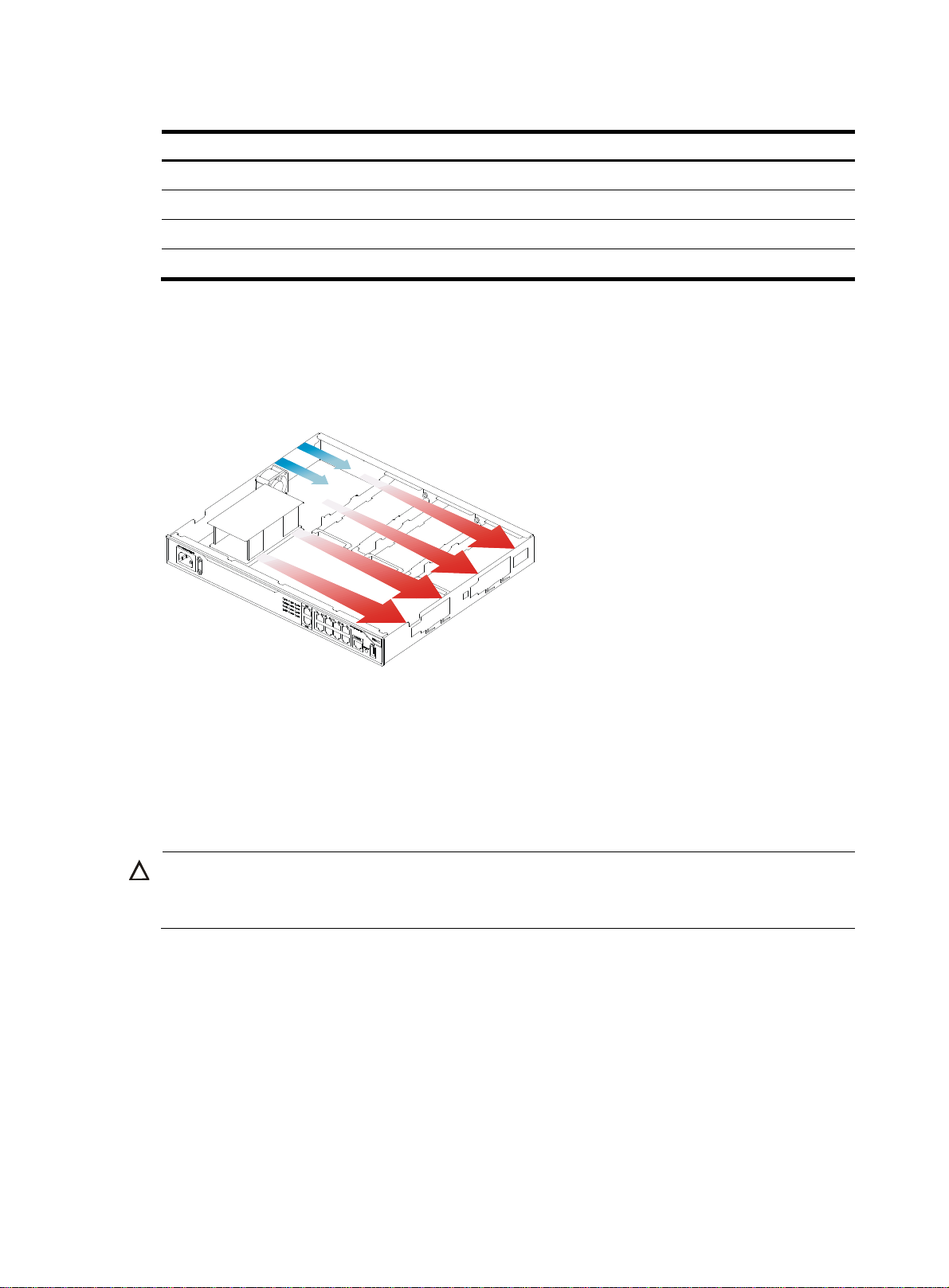
Table 4 Harmful gas limits in the equipment room
g
Gas Max. (mg/m3)
SO2 0.2
H2S 0.006
NH
3
Cl
2
Cooling system
The MSR1000 router adopts left to right airflow for heat dissipation.
Figure 1 Airflow through the MSR1000 chassis
0.05
0.01
To ensure good ventilation, the following requirements must be met:
• Leave at least 10 cm (3.94 in) of clearance at the air inlet and outlet vents.
• The installation site has a good cooling system.
ESD prevention
CAUTION:
Check the resistance of the ESD wrist strap for safety. Make sure the resistance reading is in the ran
1 to 10 megohm (Mohm) between human body and the ground.
To prevent electrostatic discharge (ESD), follow these guidelines:
• Make sure the router and the floor are reliably grounded.
• Take dust-proof measures for the equipment room.
• Maintain the humidity and temperature at a compliant level.
• Always wear an ESD wrist strap and ESD cloth when touching a circuit board or transceiver module.
An MSR1000 router does not supply an ESD wrist wrap. Prepare an ESD wrist wrap yourself.
• Place the removed interface module on an antistatic workbench, with the face upward, or put it into
an antistatic bag.
e of
3

EMI
• Touch only the edges, instead of electronic components when you observe or move a removed
interface module.
To attach an ESD wrist strap:
1. Wear the wrist strap on your wrist.
2. Lock the wrist strap tight around your wrist to keep good contact with the skin.
3. Insert the ESD plug into the ESD socket on the chassis.
All electromagnetic interference (EMI) sources, from outside or inside of the router and application system,
adversely affect the router in the following ways:
• A conduction pattern of capacitance coupling.
• Inductance coupling.
• Electromagnetic wave radiation.
• Common impedance (including the grounding system) coupling.
To prevent EMI, perform the following tasks:
• If AC power is used, use a single-phase three-wire power receptacle with protection earth (PE) to
filter interference from the power grid.
• Keep the router far away from radio transmitting stations, radar stations, and high-frequency
devices.
• Use electromagnetic shielding, for example, shielded interface cables, when necessary.
Lightning protection
To better protect the MSR1000 router from lightning, perform the following tasks:
• Make sure the grounding cable of the chassis is reliably grounded.
• Make sure the grounding terminal of the AC power receptacle is reliably grounded.
• Install a lightning arrester at the input end of the power supply to enhance the lightning protection
capability of the power supply.
• Install a special lightning arrester at the input end of outdoor signal lines (for example, E1/T1 line)
to which interface modules of the router are connected to enhance the lightning protection
capability.
Rack-mounting
Before mounting the router in a rack, make sure the following requirements are met:
• The rack has a good ventilation system.
• The rack is sturdy enough to support the router and its accessories.
• The rack has enough space to accommodate the router.
• The front and rear of the rack are at least 0.8 m (2.62 ft) away from walls or other devices. Leave
enough clearance on both sides of the rack.
• The height of the equipment room is no less than 3 m (9.84 ft).
4
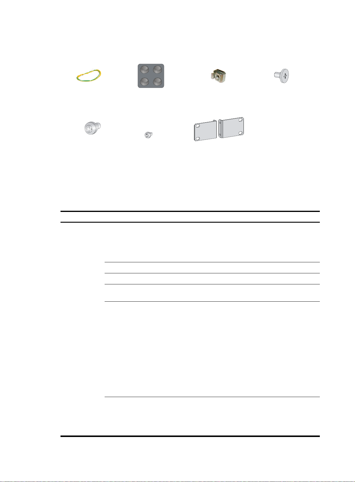
Installation accessories
Grounding cable (provided)
M6 screw (user supplied)
Rubber feet (provided)
Installation checklist
Table 5 Installation checklist
Item Requirements
Ventilation
Temperature 0°C to 45°C (32°F to 113°F).
Cage nut (user supplied)
Mounting brackets (provided)M4 screw (provided)
Load-bearing screw (provided)
• There is a minimum clearance of 10 cm (3.94 in)
around the inlet and outlet air vents for heat
dissipation of the router chassis.
• A good ventilation system is available at the
installation site.
Result
Installation site
Relative humidity 5% to 90% (noncondensing).
• Dust concentration ≤ 3 × 10
visible dust on desk within three days.)
4
particles/m3. (No
• The equipment and floor are reliably grounded.
• The equipment room is dust-proof.
• The humidity and temperature are at a compliant
level.
• Wear an ESD wrist strap and uniform when
ESD prevention
touching a circuit board.
• Place the removed interface module on an
antistatic workbench, with the face upward, or put
it into an antistatic bag.
• Touch only the edges, instead of electronic
components when observing or moving a removed
interface module.
• Take effective measures to reduce interference
from the power grid system.
• Separate the grounding equipment of the router
from the grounding or lightning protection
grounding equipment of other devices as far as
Cleanness
EMI prevention
5

Safety
precautions
Installation tools
and access
Reference
ories
possible.
• dar
Keep the router far away from radio stations, ra
-frequency devices working in high
.
Lightning
protection
and high
current.
• Use electromagnetic shielding when necessary
• ng cable of the chassis is reliably
The groundi
grounded.
The grounding terminal of the AC
• power
receptacle is reliably grounded.
• A port lightning arrester is installed. (Optional.)
• A power lightning arrester is installed. (Optional.)
A signal lightning arrester is installed at the i
• nput
end of an external signal cable. (Optional.)
• Equip an uninterrupted power supply (UPS).
Electricity safety
Workbench
• nt
The emergency power switch in the equipme
room is located.
• The workbench is stable enough.
• The workbench is reliably grounded.
• The rack has a good ventilation system.
• The rack is sturdy enough to support the weight of
Rack-mounting
requirements
the router and installation accessories.
• The size of the rack is appropriate for the ro
• The front and rear of the rack are at lea
(2.62 ft) away from walls or other devices.
• The router is far away from any moist area and heat s
• The emergency powe
• Installation accessories supplied with
r switch in the equipment room is l
the router.
st 0.8 m
ource.
ocated.
uter.
• User supplied tools.
• Documents shipped with the router.
• Online documents.
6

W
g
Installing the router
ARNING!
To avoid injury, do not touch bare wires, terminals, or parts with high-voltage hazard signs.
IMPORTANT:
• The barcode on the router chassis contains product information that must be provided to local sales
agent before you return a faulty router for service.
• Keep the tamper-proof seal on a mountin
chassis, contact HP for permission. Otherwise, HP shall not be liable for any consequence.
Installation prerequisites
• You have read "Preparing for installation" carefully.
• All requirements in "Preparing for installation" are met.
Installation flowchart
You can install the router on a workbench or on a rack. Select an installation method according to the
installation environment, and follow the installation flowchart shown in Figure 2.
screw on the chassis cover intact, and if you want to open the
7
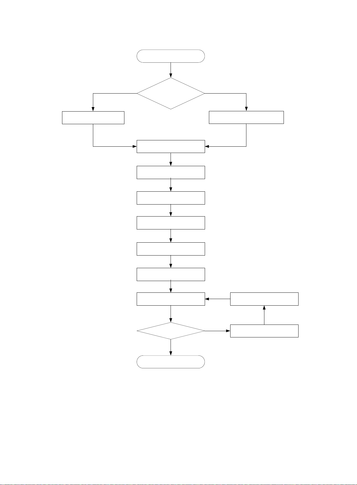
Figure 2 Installation flow
Start
Workbench-mounting
Mount the router on a
workbench
Determine the
Rack-mounting
installation position
Mount the router in a rack
Ground the router
Install interface modules
Connect interface cables
Connect the router to a
configuration terminal
Connect the power cord
Verify the installation
Power on the router Troubleshoot the router
Power off the routerOperating correctly?
No
Yes
End
8
W
g
Installing the router
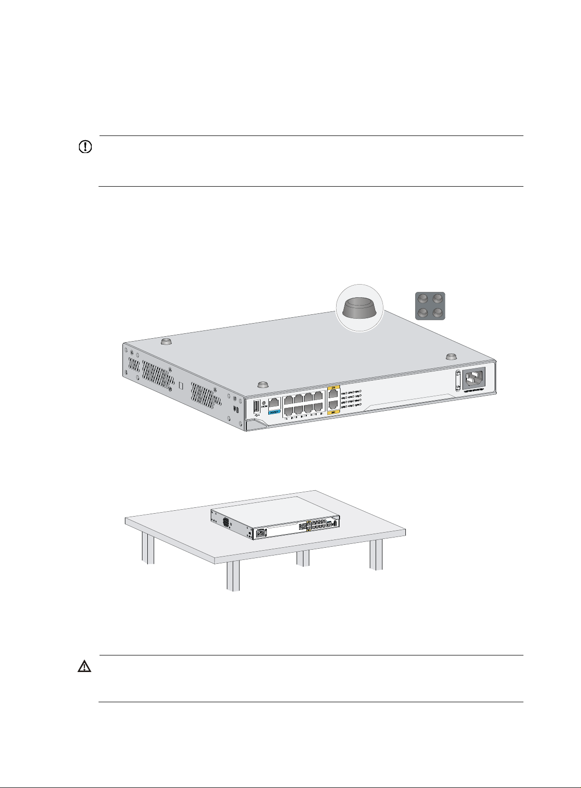
Mounting the router on a workbench
IMPORTANT:
• Allow 10 cm (3.94 in) of clearance around the chassis for heat dissipation.
• Do not place heavy objects on the router.
To mount the router on a workbench:
1. Make sure the workbench is clean, stable, and reliably grounded.
2. Place the router upside down on the workbench and attach the rubber feet to the four round holes
in the chassis bottom.
Figure 3 Attaching the rubber feet
3. Place the router on the workbench with the upside up.
Figure 4 Mounting the router on a workbench
Installing the router in a rack
ARNING!
The mountin
place any objects on the router.
brackets can only support the weight of the router. To avoid damage to the router, do not
To install the router in a rack:
9
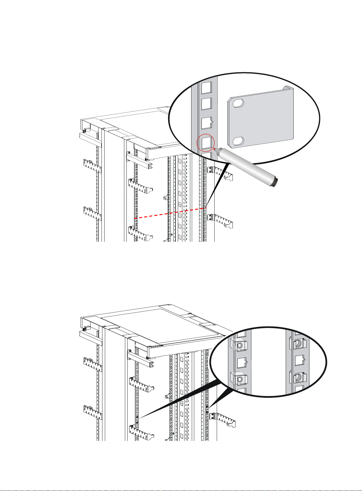
1. Use a mounting bracket to mark the positions of cage nuts on the front rack posts, making sure the
cage nuts on the two front rack posts are at the same level.
Figure 5 Marking the positions of cage nuts
2. Insert one edge of a cage nut into the hole. Use a flat-blade screwdriver to compress the other edge
of the cage nut, and then push the cage nut fully into the hole.
3. Repeat step 3 to install other cage nuts to all the marked positions on the front rack posts.
Figure 6 Installing cage nuts
10
 Loading...