

Page 1

HP MSR1000 Routers
Installation Guide
Part number: 5998-7749
Document version: 6W102-20150814
Page 2

Legal and notice information
© Copyright 2015 Hewlett-Packard Development Company, L.P.
No part of this documentation may be reproduced or transmitted in any form or by any means without
prior written consent of Hewlett-Packard Development Company, L.P.
The information contained herein is subject to change without notice.
HEWLETT-PACKARD COMPANY MAKES NO WARRANTY OF ANY KIND WITH REGARD TO THIS
MATERIAL, INCLUDING, BUT NOT LIMITED TO, THE IMPLIED WARRANTIES OF MERCHANTABILITY
AND FITNESS FOR A PARTICULAR PURPOSE. Hewlett-Packard shall not be liable for errors contained
herein or for incidental or consequential damages in connection with the furnishing, performance, or use
of this material.
The only warranties for HP products and services are set forth in the express warranty statements
accompanying such products and services. Nothing herein should be construed as constituting an
additional warranty. HP shall not be liable for technical or editorial errors or omissions contained herein
i
Page 3

Contents
Preparing for installation ············································································································································· 1
·················································································································································· 1Safety recommendations
·························································································································································· 1
··························································································································· 1
························································································································································ 1
········································································································································· 2
······································································································································· 2
································································································································································ 2
························································································································································· 3
························································································································································· 3
············································································································································································· 4
·················································································································································· 4
··························································································································································· 4
····················································································································································· 5
·························································································································································· 5
Installing the router ······················································································································································· 7
··················································································································································· 7Installation prerequisites
························································································································································· 7
Installing the router ···························································································································································· 9
····················································································································· 9Mounting the router on a workbench
·································································································································· 9
Grounding the router ····················································································································································· 12
Grounding the router through the rack ··············································································································· 12
Grounding the router with a grounding strip ····································································································· 14
············································· 15Grounding the router with a grounding conductor buried in the earth ground
······································································································································· 15
Installing a SIC ······················································································································································· 15
Installing a DSIC ···················································································································································· 16
········································································································································· 17Connecting interface cables
················································································································································· 18
···························································································································· 18
································································································································· 18
·································································································································· 19
Connecting an AC power cord ···································································································································· 22
Verifying the installation ················································································································································ 22
·················································································································································· 22Powering on the router
···································································································································· 22
········································································································································· 23
································································································································· 23
··················································································································· 25
····················································································································· 25
Safety symbols
General safety recommendations
Electricity safety
Examining the installation site
Temperature and humidity
Cleanliness
Cooling system
ESD prevention
EMI
Lightning protection
Rack-mounting
Installation accessories
Installation checklist
Installation flowchart
Installing the router in a rack
Installing an interface module
Attaching a USB device
Logging in through the console port
Connecting a console cable
Setting terminal parameters
Verifying before power-on
Powering on the router
Observing boot information
Examining the router after power-on
Configuring basic settings for the router
Replacement procedure ············································································································································· 26
Replacing a SIC ····························································································································································· 26
··························································································································································· 26Replacing a DSIC
Troubleshooting ·························································································································································· 28
······················································································································································ 28Power supply failure
····································································································································· 28
i
System configuration problems
Page 4

No terminal display ·············································································································································· 28
Garbled terminal display ······································································································································ 29
No response from the serial port ························································································································· 29
Restoring the factory settings ········································································································································ 29
Scenario 1 ······························································································································································ 29
Scenario 2 ······························································································································································ 29
Scenario 3 ······························································································································································ 29
Reset button usage guidelines ······························································································································ 30
Appendix A Chassis views and technical specifications ························································································ 31
Chassis views ································································································································································· 31
MSR1002-4 ··························································································································································· 31
MSR1003-8 ··························································································································································· 32
MSR1003-8S ························································································································································· 32
Technical specifications ················································································································································· 33
Appendix B LEDs ························································································································································ 34
Panel LEDs ······································································································································································· 34
LED description ······························································································································································· 35
Appendix C Slot arrangement ·································································································································· 36
Support and other resources ····································································································································· 37
Contacting HP ································································································································································ 37
Subscription service ·············································································································································· 37
Related information ························································································································································ 37
Documents ······························································································································································ 37
Websites ································································································································································· 37
Conventions ···································································································································································· 38
Index ··········································································································································································· 40
ii
Page 5
Preparing for installation
The HP MSR1000 Router Series includes the models in Table 1.
Table 1 HP MSR1000 Router Series models
Router model Product code HP description RMN
MSR1002-4 JG875A HP MSR1002-4 Router BJNGA-BB0034
MSR1003-8 JG732A HP MSR1003-8 Router BJNGA-BB0029
MSR1003-8S JH060A HP MSR1003-8S Router BJNGA-BB0029
IMPORTANT:
For regulatory identification purposes, every MSR1000 router is assigned a regulatory model number
(RMN). These regulatory model numbers should not be confused with the marketing name HP MSR100X or
the product code.
Safety recommendations
Safety symbols
When reading this document, note the following symbols:
WARNIN G means an alert that calls attention to important information that if not understood or
followed can result in personal injury.
CAUTION means an alert that calls attention to important information that if not understood or
followed can result in data loss, data corruption, or damage to hardware or software.
General safety recommendations
• Keep the chassis and installation tools away from walk areas.
• Make sure the ground is dry and flat and anti-slip measures are in place.
• Unplug all the external cables (including the power cord) before moving the chassis.
Electricity safety
• Locate the emergency power-off switch in the room before installation. Shut the power off at once in
case accident occurs. Disconnect the power cord of the router if necessary.
• Make sure the router is reliably grounded.
• Do not open or close the chassis cover when the router is powered on.
1
Page 6

• Correctly connect the interface cables of the router.
p
y
p
• Use an uninterrupted power supply (UPS).
• Do not work alone when the router has power.
• Before installation and replacement, make sure the power has been disconnected.
Examining the installation site
The router must be used indoors. To ensure correct operation and long service life of your router, the
installation site must meet the following requirements.
Temperature and humidity
You must maintain a compliant temperature and humidity in the equipment room as described in Table
2.
• Lasting high relative humidity can cause poor insulation, electricity creepage, mechanical property
change of materials, and metal corrosion.
• Lasting low relative humidity can cause washer contraction and ESD and introduce problems such
as loose captive screws and circuit failure.
• High temperature can accelerate the aging of insulation materials and significantly lower the
reliability and lifespan of the switch.
Table 2 Temperature and humidity requirements
erature Humidit
Tem
0°C to 45°C (32°F to 113°F) 5% to 90% (noncondensing)
Cleanliness
Dust buildup on the chassis might result in electrostatic adsorption, which causes poor contact of metal
components and contact points, especially when indoor relative humidity is low. In the worst case,
electrostatic adsorption can cause communication failure.
Table 3 Dust concentration limit in the equipment room
Substance
Dust particles
NOTE:
Dust particle diameter ≥ 5 μm
The equipment room must also meet limits on salts, acids, and sulfides to eliminate corrosion and
premature aging of components, as shown in Table 4.
Concentration limit (
≤ 3 x 10
(No visible dust on desk in three days.)
4
articles/m3)
2
Page 7
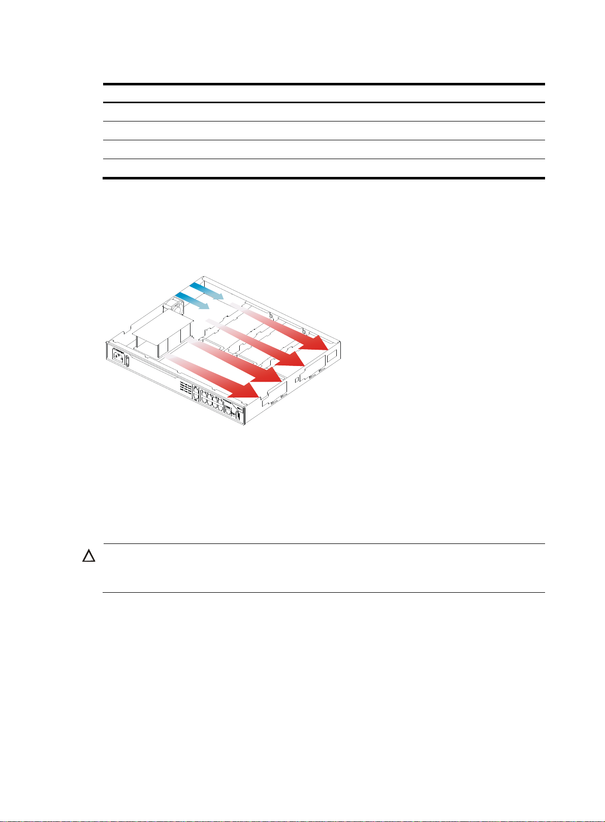
Table 4 Harmful gas limits in the equipment room
g
Gas Max. (mg/m3)
SO2 0.2
H2S 0.006
NH
3
Cl
2
Cooling system
The MSR1000 router adopts left to right airflow for heat dissipation.
Figure 1 Airflow through the MSR1000 chassis
0.05
0.01
To ensure good ventilation, the following requirements must be met:
• Leave at least 10 cm (3.94 in) of clearance at the air inlet and outlet vents.
• The installation site has a good cooling system.
ESD prevention
CAUTION:
Check the resistance of the ESD wrist strap for safety. Make sure the resistance reading is in the ran
1 to 10 megohm (Mohm) between human body and the ground.
To prevent electrostatic discharge (ESD), follow these guidelines:
• Make sure the router and the floor are reliably grounded.
• Take dust-proof measures for the equipment room.
• Maintain the humidity and temperature at a compliant level.
• Always wear an ESD wrist strap and ESD cloth when touching a circuit board or transceiver module.
An MSR1000 router does not supply an ESD wrist wrap. Prepare an ESD wrist wrap yourself.
• Place the removed interface module on an antistatic workbench, with the face upward, or put it into
an antistatic bag.
e of
3
Page 8

EMI
• Touch only the edges, instead of electronic components when you observe or move a removed
interface module.
To attach an ESD wrist strap:
1. Wear the wrist strap on your wrist.
2. Lock the wrist strap tight around your wrist to keep good contact with the skin.
3. Insert the ESD plug into the ESD socket on the chassis.
All electromagnetic interference (EMI) sources, from outside or inside of the router and application system,
adversely affect the router in the following ways:
• A conduction pattern of capacitance coupling.
• Inductance coupling.
• Electromagnetic wave radiation.
• Common impedance (including the grounding system) coupling.
To prevent EMI, perform the following tasks:
• If AC power is used, use a single-phase three-wire power receptacle with protection earth (PE) to
filter interference from the power grid.
• Keep the router far away from radio transmitting stations, radar stations, and high-frequency
devices.
• Use electromagnetic shielding, for example, shielded interface cables, when necessary.
Lightning protection
To better protect the MSR1000 router from lightning, perform the following tasks:
• Make sure the grounding cable of the chassis is reliably grounded.
• Make sure the grounding terminal of the AC power receptacle is reliably grounded.
• Install a lightning arrester at the input end of the power supply to enhance the lightning protection
capability of the power supply.
• Install a special lightning arrester at the input end of outdoor signal lines (for example, E1/T1 line)
to which interface modules of the router are connected to enhance the lightning protection
capability.
Rack-mounting
Before mounting the router in a rack, make sure the following requirements are met:
• The rack has a good ventilation system.
• The rack is sturdy enough to support the router and its accessories.
• The rack has enough space to accommodate the router.
• The front and rear of the rack are at least 0.8 m (2.62 ft) away from walls or other devices. Leave
enough clearance on both sides of the rack.
• The height of the equipment room is no less than 3 m (9.84 ft).
4
Page 9
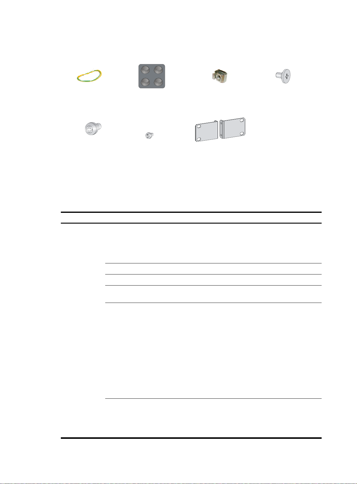
Installation accessories
Grounding cable (provided)
M6 screw (user supplied)
Rubber feet (provided)
Installation checklist
Table 5 Installation checklist
Item Requirements
Ventilation
Temperature 0°C to 45°C (32°F to 113°F).
Cage nut (user supplied)
Mounting brackets (provided)M4 screw (provided)
Load-bearing screw (provided)
• There is a minimum clearance of 10 cm (3.94 in)
around the inlet and outlet air vents for heat
dissipation of the router chassis.
• A good ventilation system is available at the
installation site.
Result
Installation site
Relative humidity 5% to 90% (noncondensing).
• Dust concentration ≤ 3 × 10
visible dust on desk within three days.)
4
particles/m3. (No
• The equipment and floor are reliably grounded.
• The equipment room is dust-proof.
• The humidity and temperature are at a compliant
level.
• Wear an ESD wrist strap and uniform when
ESD prevention
touching a circuit board.
• Place the removed interface module on an
antistatic workbench, with the face upward, or put
it into an antistatic bag.
• Touch only the edges, instead of electronic
components when observing or moving a removed
interface module.
• Take effective measures to reduce interference
from the power grid system.
• Separate the grounding equipment of the router
from the grounding or lightning protection
grounding equipment of other devices as far as
Cleanness
EMI prevention
5
Page 10

Safety
precautions
Installation tools
and access
Reference
ories
possible.
• dar
Keep the router far away from radio stations, ra
-frequency devices working in high
.
Lightning
protection
and high
current.
• Use electromagnetic shielding when necessary
• ng cable of the chassis is reliably
The groundi
grounded.
The grounding terminal of the AC
• power
receptacle is reliably grounded.
• A port lightning arrester is installed. (Optional.)
• A power lightning arrester is installed. (Optional.)
A signal lightning arrester is installed at the i
• nput
end of an external signal cable. (Optional.)
• Equip an uninterrupted power supply (UPS).
Electricity safety
Workbench
• nt
The emergency power switch in the equipme
room is located.
• The workbench is stable enough.
• The workbench is reliably grounded.
• The rack has a good ventilation system.
• The rack is sturdy enough to support the weight of
Rack-mounting
requirements
the router and installation accessories.
• The size of the rack is appropriate for the ro
• The front and rear of the rack are at lea
(2.62 ft) away from walls or other devices.
• The router is far away from any moist area and heat s
• The emergency powe
• Installation accessories supplied with
r switch in the equipment room is l
the router.
st 0.8 m
ource.
ocated.
uter.
• User supplied tools.
• Documents shipped with the router.
• Online documents.
6
Page 11

W
g
Installing the router
ARNING!
To avoid injury, do not touch bare wires, terminals, or parts with high-voltage hazard signs.
IMPORTANT:
• The barcode on the router chassis contains product information that must be provided to local sales
agent before you return a faulty router for service.
• Keep the tamper-proof seal on a mountin
chassis, contact HP for permission. Otherwise, HP shall not be liable for any consequence.
Installation prerequisites
• You have read "Preparing for installation" carefully.
• All requirements in "Preparing for installation" are met.
Installation flowchart
You can install the router on a workbench or on a rack. Select an installation method according to the
installation environment, and follow the installation flowchart shown in Figure 2.
screw on the chassis cover intact, and if you want to open the
7
Page 12
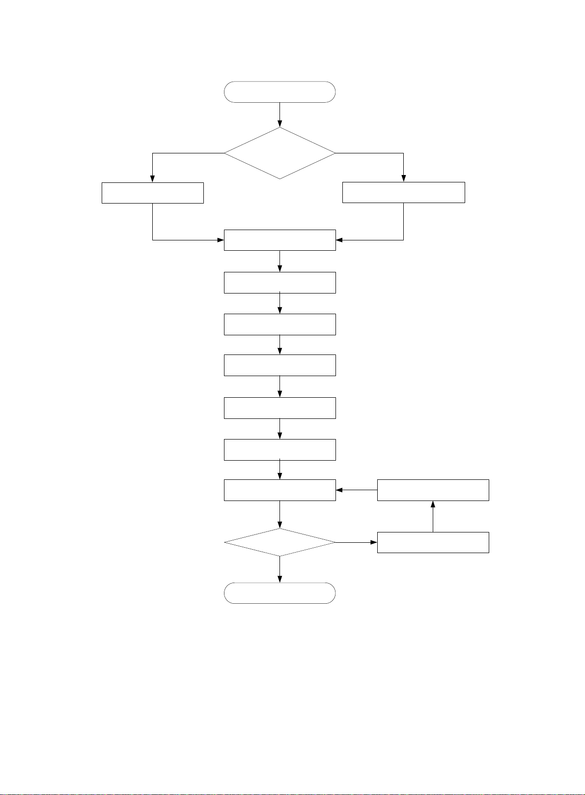
Figure 2 Installation flow
Start
Workbench-mounting
Mount the router on a
workbench
Determine the
Rack-mounting
installation position
Mount the router in a rack
Ground the router
Install interface modules
Connect interface cables
Connect the router to a
configuration terminal
Connect the power cord
Verify the installation
Power on the router Troubleshoot the router
Power off the routerOperating correctly?
No
Yes
End
8
Page 13
W
g
Installing the router
Mounting the router on a workbench
IMPORTANT:
• Allow 10 cm (3.94 in) of clearance around the chassis for heat dissipation.
• Do not place heavy objects on the router.
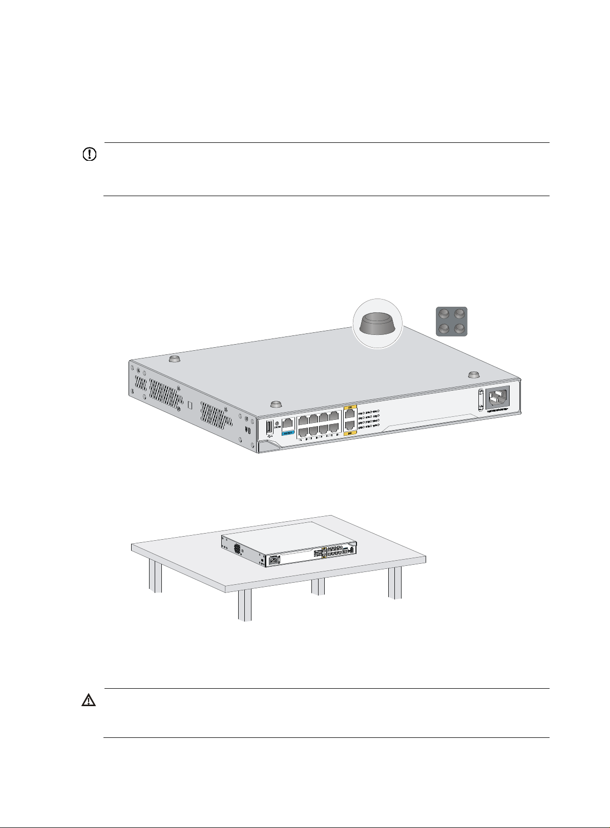
To mount the router on a workbench:
1. Make sure the workbench is clean, stable, and reliably grounded.
2. Place the router upside down on the workbench and attach the rubber feet to the four round holes
in the chassis bottom.
Figure 3 Attaching the rubber feet
3. Place the router on the workbench with the upside up.
Figure 4 Mounting the router on a workbench
Installing the router in a rack
ARNING!
The mountin
place any objects on the router.
brackets can only support the weight of the router. To avoid damage to the router, do not
To install the router in a rack:
9
Page 14
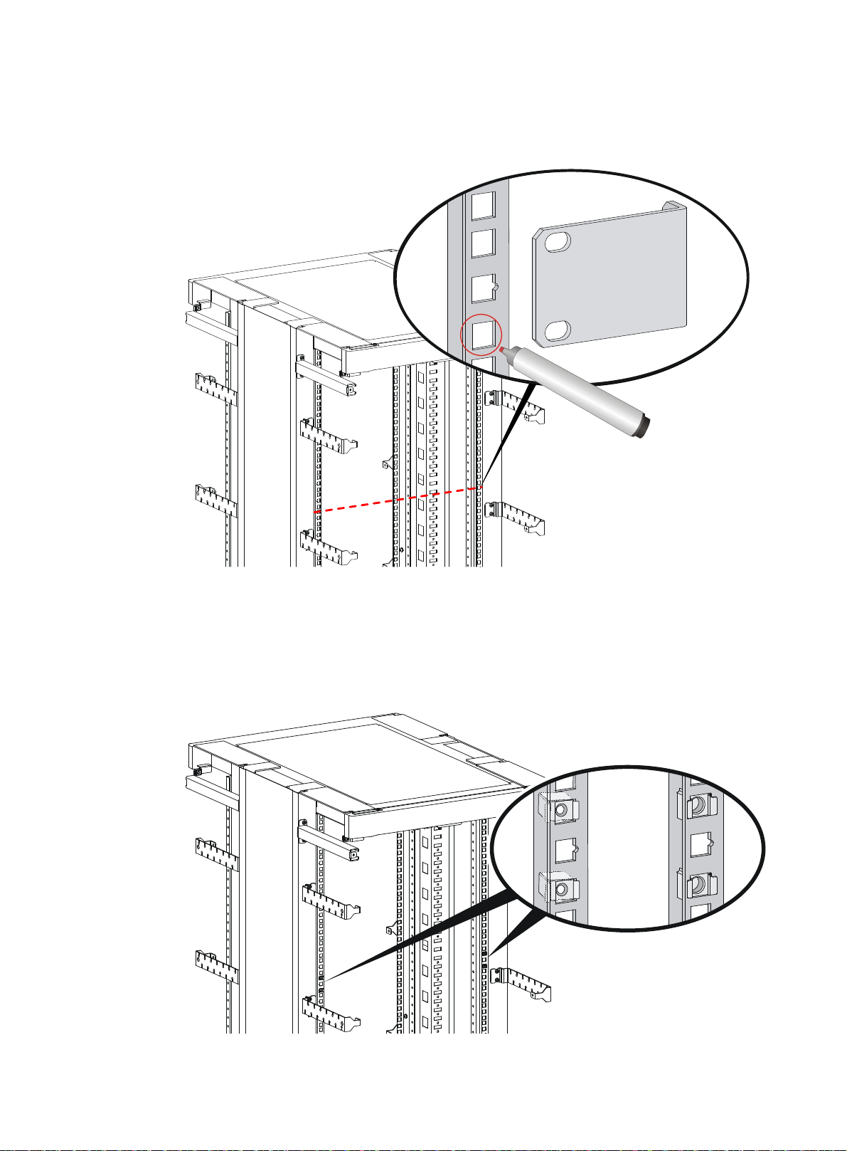
1. Use a mounting bracket to mark the positions of cage nuts on the front rack posts, making sure the
cage nuts on the two front rack posts are at the same level.
Figure 5 Marking the positions of cage nuts
2. Insert one edge of a cage nut into the hole. Use a flat-blade screwdriver to compress the other edge
of the cage nut, and then push the cage nut fully into the hole.
3. Repeat step 3 to install other cage nuts to all the marked positions on the front rack posts.
Figure 6 Installing cage nuts
10
Page 15

4. Attach the mounting brackets to the two sides of the chassis and fasten the screws.
Figure 7 Attaching the mounting brackets
5. Place the chassis on the rack and use M6 screws to attach the mounting brackets to the rack posts.
Figure 8 Securing the router to the rack
11
Page 16

W
Grounding the router
ARNING!
Correctly connecting the router grounding cable is crucial to lightning protection and EMI protection.
IMPORTANT:
The resistance reading should be smaller than 5 ohms between the chassis and the ground.
Grounding the router through the rack
IMPORTANT:
Make sure the rack is reliably grounded before grounding the router.
To connect the grounding cable:
1. Remove the grounding screw from the grounding hole at the rear of the chassis.
2. Use the grounding screw to attach the ring terminal of the grounding cable to the chassis.
See Figure 9.
3. Remove the hex nut from a grounding post on the rack's grounding bar.
4. Use needle-nose pliers to bend a hook at the other end of the grounding cable, attach it to the
grounding post, and reinstall the hex nut. See Figure 9.
12
Page 17

Figure 9 Grounding the router through the rack (1)
13
Page 18

Figure 10 Grounding the router through the rack (2)
1
2
Grounding the router with a grounding strip
If a grounding strip is available at the installation site, connect the grounding cable to the grounding
strip.
Follow the same procedures in "Grounding the router through the rack" to connect the grounding cable.
14
Page 19

Figure 11 Grounding the router with a grounding strip
Grounding the router with a grounding conductor buried in the earth ground
If the installation site has no grounding strips, but earth ground is available, hammer a 0.5 m (1.64 ft) or
longer angle iron or steel tube into the earth ground to serve as a grounding conductor. The steel tube
must be zinc-coated. Weld the yellow-green grounding cable to the angel iron or steel tube and treat the
joint for corrosion protection.
Installing an interface module
Installing a SIC
CAUTION:
SICs are not hot swappable. Make sure the router is powered off before installing a SIC.
To install a SIC:
1. Remove the fastening screws on the filler panel with a Phillips screwdriver and remove the filler
panel.
Keep the removed filler panel for future use.
2. Push the SIC slowly along the slide rails into the slot until it makes close contact with the backplane
of the router.
3. Use a Phillips screwdriver to fasten the captive screws on the SIC.
15
Page 20

Figure 12 Removing the filler panel
Figure 13 Installing the SIC
Installing a DSIC
CAUTION:
DSICs are not hot swappable. Make sure the router is powered off before installing a DSIC.
The MSR1002-4 router does not support DSICs.
To install a DSIC:
1. Remove the screws on the filler panel on slot 1 and slot 2 of the router to remove the filler panel,
as shown in Figure 14.
Figure 15. 2. Loosen the captive screws on the slot divider and pull out the slot divider, as shown in
Figure 14 Removing the filler panel
16
Page 21

Figure 15 Removing the slot divider
3. Insert the DSIC into the slot and push it along the slide rails until it makes close contact with the
backplane of the router.
Figure 16 Installing a DSIC
4. Fasten the captive screws to secure the DSIC.
Connecting interface cables
Connect interface cables before powering on the router. This section describes how to connect Ethernet
cables. For other cable connection methods, see HP MSR Series Routers Interface Module User Guide.
To connect an Ethernet cable:
1. Plug one end of an Ethernet cable into the Ethernet port on the router.
2. Plug the other end of the cable into the Ethernet port of the peer device.
17
Page 22

W
Figure 17 Connecting the router to a PC
Attaching a USB device
CAUTION:
• Attach only HP-certified USB devices.
• To avoid data loss and hardware damage, do not remove a USB device when it is transmitting data.
• The USB port does not support hot-swapping of Sierra Wireless's USB modems.
To attach a USB device:
1. Remove the protective cap from the USB device.
2. Correctly orient the USB device and plug the connector of the USB device to the USB port.
Figure 18 Attaching a USB device
Logging in through the console port
Connecting a console cable
IMPORTANT:
hen you connect a PC to a powered-on router, connect the RJ-45 connector to the router after
connecting the DB-9 connector of the console cable to the PC.
To connect a console cable:
1. Plug the DB-9 female connector to the serial port of the configuration terminal.
18
Page 23

2. Connect the RJ-45 connector to the console port of the router.
Figure 19 Connecting the console cable
Setting terminal parameters
This section uses a PC with Windows XP as an example.
To set terminal parameters:
1. Select Start > All Programs > Accessories > Communications > HyperTerminal.
The Connection Description dialog box appears.
Figure 20 Connection description
2. Select the serial port to be used from the Connect using list, and click OK.
19
Page 24

Figure 21 Setting the serial port used by the HyperTerminal connection
3. Set Bits per second to 9600, Data bits to 8, Parity to None, Stop bits to 1, and Flow control to None,
and click OK.
4. To restore the default settings, click Restore Defaults.
Figure 22 Setting the serial port parameters
5. Select File > Properties in the HyperTerminal window.
20
Page 25

Figure 23 HyperTerminal window
6. On the Settings tab, set the emulation to VT100 or Auto detect and click OK.
Figure 24 Setting terminal emulation in test Properties dialog box
21
Page 26

Connecting an AC power cord
1. Make sure the router is reliably grounded, and the power switch on the router is in the OFF
position.
2. Connect one end of the AC power cord to the AC receptacle on the router, and the other end to
the AC power source.
3. Install the bail latch and push it leftward to secure the power cord.
Figure 25 Connecting an AC power cord to the router
Verifying the installation
After you complete the installation, verify that:
• There is enough space for heat dissipation around the router, and the rack or workbench is stable.
• Interface modules are correctly installed.
• The router, rack, and power cord are reliably grounded.
• The correct power source is used.
Powering on the router
Verifying before power-on
Before powering on the router, verify the following items:
• The power modules are correctly installed.
• The power cord and grounding cable are correctly connected.
• The power source voltage meets the requirement of the router.
22
Page 27

• The console cable is correctly connected, the terminal or PC used for configuration has started, and
the configuration parameters have been set.
• If a CF card is used, verify that the CF card is in position.
• Make sure the installed interface modules are in position.
Powering on the router
1. Turn on the switch of the power supply system for the router.
2. Turn on the switch of the AC or DC power modules.
Observing boot information
Power on the router, and you can see the following information:
System is starting...
Press Ctrl+D to access BASIC-BOOTWARE MENU...
Booting Normal Extended BootWare
The Extended BootWare is self-decompressing....Done.
****************************************************************************
* *
* HP MSR1003-8S BootWare, Version 2.30 *
* *
****************************************************************************
Copyright (c) 2010-2015 Hewlett-Packard Development Company, L.P.
Compiled Date : Sep 11 2014
CPU ID : 0x8
CPU L1 Cache : 32KB
CPU L2 Cache : 256KB
Memory Type : DDR3 SDRAM
Memory Size : 1024MB
Memory Speed : 400MHz
Flash Size : 256MB
CPLD Version : 1.0
PCB Version : 2.0
BootWare Validating...
Press Ctrl+B to access EXTENDED-BOOTWARE MENU...
Loading the main image files...
Loading file flash:/msr100x-cmw710-system-e030206.bin.......................
.................................Done.
Loading file flash:/msr100x-cmw710-security-e030206.bin....Done.
Loading file flash:/msr100x-cmw710-voice-e030206.bin....Done.
Loading file flash:/msr100x-cmw710-data-e030206.bin......Done.
Loading file flash:/msr100x-cmw710-boot-e030206.bin........Done.
23
Page 28

Image file flash:/msr100x-cmw710-boot-e030206.bin is self-decompressing.....
....Done.
System image is starting...
Cryptographic Algorithms Known-Answer Tests are running ...
CPU 0 of slot 0 in chassis 0:
Starting Known-Answer tests in the user space.
Known-answer test for SHA1 passed.
Known-answer test for SHA224 passed.
Known-answer test for SHA256 passed.
Known-answer test for SHA384 passed.
Known-answer test for SHA512 passed.
Known-answer test for HMAC-SHA1 passed.
Known-answer test for HMAC-SHA224 passed.
Known-answer test for HMAC-SHA256 passed.
Known-answer test for HMAC-SHA384 passed.
Known-answer test for HMAC-SHA512 passed.
Known-answer test for AES passed.
Known-answer test for RSA(signature/verification) passed.
Known-answer test for RSA(encrypt/decrypt) passed.
Known-answer test for DSA(signature/verification) passed.
Known-answer test for random number generator passed.
Known-Answer tests in the user space passed.
Starting Known-Answer tests in the kernel.
Known-answer test for SHA1 passed.
Known-answer test for HMAC-SHA1 passed.
Known-answer test for AES passed.
Known-answer test for random number generator passed.
Known-Answer tests in the kernel passed.
Starting Known-Answer tests in the engine.
Known-answer test for SHA1 passed.
Known-answer test for HMAC-SHA1 passed.
Known-answer test for AES passed.
Known-answer test for RSA(signature/verification) passed.
Known-answer test for RSA(encrypt/decrypt) passed.
Known-answer test for DSA(signature/verification) passed.
Known-answer test for random number generator passed.
Known-Answer tests in the engine passed.
Cryptographic Algorithms Known-Answer Tests passed.
Line aux0 is available.
Press ENTER to get started.
Press Enter, and the following prompt appears:
<sysname>
You can now configure the router.
24
Page 29

Examining the router after power-on
After the router is powered on, verify that:
• The LEDs on the front panel are operating correctly:
LED
PWR Steady green The power module is supplying power correctly.
SYS Slow flashing green The router is operating correctly.
• The configuration terminal displays information correctly. For local configuration, the configuration
terminal displays the boot information (see "Observing boot information").
• If you press Enter as prompted after system bootup, the router is ready to configure.
Status
Description
Configuring basic settings for the router
After the router is powered on for the first time, configure the basic settings for the router. For information
about configuring the MSR1003-8 router, see HP MSR Routers Fundamentals Configuration Guide (V5)
and HP MSR Routers Fundamentals Command Reference (V5). For information about configuring the
MSR1002-4 and MSR1003-8S routers, see HP MSR Routers Fundamentals Configuration Guide (V7) and
HP MSR Routers Fundamentals Command Reference (V7).
25
Page 30

Replacement procedure
CAUTION:
SICs and DSICs are not hot swappable. Make sure the router is powered off before replacing a SIC or
DSIC.
Replacing a SIC
1. Loosen the captive screws on the SIC.
2. Gently pull the SIC out along the slide rails.
3. Install a new SIC. For the installation procedure, see "Installing the router."
If you do not install a SIC, install a filler panel and tighten the screws.
Figure 26 Removing a SIC
Figure 27 Installing a filler panel
Replacing a DSIC
1. Loosen the captive screws on the DSIC.
2. Gently pull the DSIC out along the slide rails.
If you need to install a DSIC or SICs, see "Installing the router" for the installation procedure.
26
Page 31

To install filler panels, proceed to steps 3 and 4.
3. Gently push the slot divider into the DSIC slot along the slide rails and tighten the screws.
4. Install the filler panels and tighten the screws.
Figure 28 Removing a DSIC
Figure 29 Installing the slot divider
Figure 30 Installing filler panels
27
Page 32

g
Troubleshooting
IMPORTANT:
• The barcode on the router chassis contains product information that must be provided to local sales
agent before you return a faulty router for service.
• Keep the tamper-proof seal on a mountin
chassis, contact HP for permission. Otherwise, HP shall not be liable for any consequence.
screw on the chassis cover intact, and if you want to open the
Power supply failure
If the router cannot be powered on and LEDs on the front panel are off, the power supply is faulty.
To troubleshoot the power supply:
1. Power off the router.
2. Verify that the router's power cords are connected correctly.
3. Verify that the power source is operating correctly.
4. Determine if the power cord is damaged.
5. If the problem persists, contact HP Support.
System configuration problems
If the configuration environment setup is correct, the console terminal displays boot information when the
router is powered on. If the setup is incorrect, the console terminal displays nothing or garbled text.
No terminal display
If the console terminal displays nothing when the router is powered on, verify the following items:
• The power supply system is operating correctly.
• The console cable is connected correctly.
• The console cable is connected to the serial port that is configured for the console terminal.
• The console terminal properties are set as follows:
{ Baud rate—9,600
{ Data bits—8
{ Parity—none
{ Stop bits—1
{ Flow control—none
• The console cable is operating correctly.
28
Page 33

Garbled terminal display
If terminal display is garbled, make sure the Data bits field for the console terminal is set to 8. If the Data
bits field is set to 5 or 6, the console terminal will display garbled characters.
No response from the serial port
If the serial port does not respond, verify that the serial cable is in good condition and the serial port
settings are correct.
Restoring the factory settings
Scenario 1
Symptom
When you replace the router, the router password is lost. As a result, you cannot log in to the router and
do not know the router configuration.
Solution
Because the router is replaced, you do not need to save the configuration of the router. In this case, you
can press the Reset button for more than 4 seconds to reboot the router and restore the factory settings.
Then, you can use the username and password shipped with the router to log in to the router.
When the router configuration must be saved and you have a console cable, you can log in to the router
from the BootWare menu.
Scenario 2
Symptom
After the configuration is modified, the network connectivity is lost. When you check the configuration,
the configuration is very complicated and it is hard to locate the errors. In this case, you must configure
the router again.
Solution
If you have not saved any configuration, you can reboot the router by pressing the Reset button for a short
time or power off the router.
If you have saved the configuration, delete the configuration file at the CLI, and press the Reset button to
restore the factory settings.
Scenario 3
Symptom
The router crashes.
Solution
Press the Reset button for a short time to reboot the router.
29
Page 34

Reset button usage guidelines
An MSR1000 router provides the Reset button. You can use the button to reboot the system or restore the
factory settings.
1. Press the Reset button for a short time to reboot the router.
2. Press the Reset button for more than 4 seconds to reboot the router and restore the factory settings.
30
Page 35

Appendix A Chassis views and technical specifications
Chassis views
The following figures are for illustration only.
MSR1002-4
Figure 31 Front view
(1) Power receptacle (2) Gigabit Ethernet port (GE0)
(4) SFP port (SFP5) (5) Asynchronous/synchronous
serial interface (SERIAL0)
(7) Reset button (RESET) (8) USB port
Figure 32 Rear view
(1) SIC slot 2 (2) SIC slot 1
(3) Gigabit Ethernet ports (GE1 to GE4)
(6) Console port/AUX port (CON/AUX)
(3) Grounding terminal
31
Page 36

MSR1003-8
Figure 33 Front view
(1) Power receptacle (2) Gigabit Ethernet port (GE1)
(4) Console port/AUX port
(CON/AUX)
(7) Gigabit Ethernet port (GE0)
Figure 34 Rear view
(1) SIC slot 3 (2) SIC slot 2
(3) SIC slot 1 (4) Grounding terminal
MSR1003-8S
Figure 35 Front view
(3) Gigabit Ethernet ports (GE2 to GE8)
(5) Reset button (RESET) (6) USB port
(1) Power receptacle (2) Gigabit Ethernet port (GE1) (3) Gigabit Ethernet ports (GE2 to GE8)
(4) Console port/AUX port
(CON/AUX)
(7) Gigabit Ethernet port (GE0)
(5) Reset button (RESET) (6) USB port
32
Page 37

Figure 36 Rear view
(1) SIC slot 3 (2) SIC slot 2
(3) SIC slot 1 (4) Grounding terminal
Technical specifications
Item MSR1002-4
Console/AUX port 1 1 1
USB port 1 1 1
Gigabit Ethernet port 5 10 10
SFP port 1 N/A N/A
Asynchronous/synchr
onous serial interface
Memory 1 GB DDR3 1 GB DDR3 1 GB DDR3
Flash 256 MB 256 MB 256 MB
SIC/DSIC slot 2 SIC slot (1 DSIC slot) 3 SIC slots (1 DSIC slot) 3 SIC slots (1 DSIC slot)
Dimensions (H × W ×
D)
(excluding rubber feet
and mounting
brackets)
AC power supply
Rated power for AC
power supply
1 N/A N/A
44.2 × 360 × 300 mm
(1.74 × 14.17 ×
11.81 in)
Rated voltage range:
90 VAC to 264 VAC
@ 50 Hz/60 Hz
30 W 30 W 30 W
MSR1003-8
44.2 × 360 × 300 mm (1.74
× 14.17 × 11.81 in)
Rated voltage range: 90
VAC to 264 VAC @ 50
Hz/60 Hz
MSR1003-8S
44.2 × 360 × 300 mm
(1.74 × 14.17 × 11.81 in)
Rated voltage range: 90
VAC to 264 VAC @ 50
Hz/60 Hz
Operating
temperature
Relative humidity
(noncondensing)
0°C to 45°C (32°F to
113°F)
5% to 90% 5% to 90% 5% to 90%
0°C to 45°C (32°F to 113°F)
33
0°C to 45°C (32°F to
113°F)
Page 38

Appendix B LEDs
Panel LEDs
Figure 37 MSR1002-4 LEDs
4
3
2
1
(1) Asynchronous/synchronous
serial interface LED (SERIAL0)
(4) System status LED (SYS) (5) 10/100 Mbps link LED for the
5 6
5 6
(2) SFP port LED (SFP5) (3) Power supply LED (PWR)
(6) 1000 Mbps link LED for the
Gigabit Ethernet port
Gigabit Ethernet port
Figure 38 MSR1003-8 LEDs
(1) System LED (SYS) (2) Power supply LED (PWR) (3) Gigabit Ethernet port LEDs (GE0 to GE9)
Figure 39 MSR1003-8S LEDs
(1) System LED (SYS) (2) Power supply LED (PWR) (3) Gigabit Ethernet port LEDs (GE0 to GE9)
34
Page 39

LED description
LED State Description
SYS
PWR
SERIAL0
GE
1000 Mbps
link LED
10/100
Mbps link
LED
Flashing green (1 Hz)
Flashing green (8 Hz) The BootWare runs.
Steady green The SDRAM is performing self-test.
Flashing yellow (1 Hz) The DDR3 SDRAM has failed the self-test.
Flashing yellow (8 Hz) The extended segment does not exist.
Steady yellow The boot image does not exist.
Off No power input, or exceptions have occurred.
Steady green The power supply is operating correctly.
Off No power input.
Steady green A link is present.
Flashing green Data is being received or transmitted.
Off No link is present.
Steady green A 1000 Mbps link is present.
Flashing green Data is being received or transmitted at 1000 Mbps.
Off No 1000 Mbps link is present.
Steady yellow A 10/100 Mbps link is present.
Flashing yellow
Off No 10/100 Mbps link is present.
Comware has started with the configuration file and
the router has booted up.
Data is being received or transmitted at 10/100
Mbps.
SFP
Steady green A 1000 Mbps link is present.
Flashing green Data is being received or transmitted at 1000 Mbps.
Steady yellow A 10/100 Mbps link is present.
Flashing yellow
Off No link is present.
35
Data is being received or transmitted at 10/100
Mbps.
Page 40

g
Appendix C Slot arrangement
The router provides slots for SICs. A DSIC can be installed if you remove the slot divider between two SIC
slots.
The slot number of fixed ports on the router is 0.
Table 6 Slot arrangement on the router
Router Slot arran
MSR1002-4
MSR1003-8
MSR1003-8S
: SIC slot
: DSIC slot
ement
36
Page 41

Support and other resources
Contacting HP
For worldwide technical support information, see the HP support website:
http://www.hp.com/support
Before contacting HP, collect the following information:
• Product model names and numbers
• Technical support registration number (if applicable)
• Product serial numbers
• Error messages
• Operating system type and revision level
• Detailed questions
Subscription service
HP recommends that you register your product at the Subscriber's Choice for Business website:
http://www.hp.com/go/wwalerts
After registering, you will receive email notification of product enhancements, new driver versions,
firmware updates, and other product resources.
Related information
Documents
To find related documents, browse to the Manuals page of the HP Business Support Center website:
http://www.hp.com/support/manuals
• For related documentation, navigate to the Networking section, and select a networking category.
• For a complete list of acronyms and their definitions, see HP FlexNetwork Technology Acronyms.
Websites
• HP.com http://www.hp.com
• HP manuals http://www.hp.com/support/manuals
• HP download drivers and software http://www.hp.com/support/downloads
http://www.hp.com/go/networking• HP Networking
http://www.software.hp.com• HP software depot
http://www.hp.com/learn• HP Education
37
Page 42

Conventions
This section describes the conventions used in this documentation set.
Command conventions
Convention Description
Boldface Bold text represents commands and keywords that you enter literally as shown.
Italic Italic text represents arguments that you replace with actual values.
[ ] Square brackets enclose syntax choices (keywords or arguments) that are optional.
{ x | y | ... }
[ x | y | ... ]
{ x | y | ... } *
[ x | y | ... ] *
&<1-n>
# A line that starts with a pound (#) sign is comments.
GUI conventions
Convention Description
Boldface
> Multi-level menus are separated by angle brackets. For example, File > Create > Folder.
Symbols
Braces enclose a set of required syntax choices separated by vertical bars, from which
you select one.
Square brackets enclose a set of optional syntax choices separated by vertical bars, from
which you select one or none.
Asterisk-marked braces enclose a set of required syntax choices separated by vertical
bars, from which you select at least one.
Asterisk-marked square brackets enclose optional syntax choices separated by vertical
bars, from which you select one choice, multiple choices, or none.
The argument or keyword and argument combination before the ampersand (&) sign can
be entered 1 to n times.
Window names, button names, field names, and menu items are in bold text. For
example, the New User window appears; click OK.
Convention Description
WARNING
CAUTION
IMPORTANT
NOTE
TIP
An alert that calls attention to important information that if not understood or followed can
result in personal injury.
An alert that calls attention to important information that if not understood or followed can
result in data loss, data corruption, or damage to hardware or software.
An alert that calls attention to essential information.
An alert that contains additional or supplementary information.
An alert that provides helpful information.
38
Page 43

Network topology icons
Represents a generic network device, such as a router, switch, or firewall.
Represents a routing-capable device, such as a router or Layer 3 switch.
Represents a generic switch, such as a Layer 2 or Layer 3 switch, or a router that supports
Layer 2 forwarding and other Layer 2 features.
Represents an access controller, a unified wired-WLAN module, or the switching engine
on a unified wired-WLAN switch.
Represents an access point.
Represents a mesh access point.
Represents omnidirectional signals.
Represents directional signals.
Represents a security product, such as a firewall, UTM, multiservice security gateway, or
load-balancing device.
Represents a security card, such as a firewall, load-balancing, NetStream, SSL VPN, IPS,
or ACG card.
Port numbering in examples
The port numbers in this document are for illustration only and might be unavailable on your device.
39
Page 44

Index
A C D E G I L M N O P R S T V W
ESD prevention XE "preparing for installation:ESD
Attaching a USB device XE "procedure:attaching USB
device" XE "router:attaching USB device" ,
C
Chassis views XE "chassis views" XE "chassis:views"
XE "technical specifications:chassis views" ,
Cleanliness XE "preparing for installation:cleanliness"
XE "installation site:cleanliness" ,2
Configuring basic settings for the router XE
"configuring:basic settings for router" XE
"procedure:configuring basic settings for router" ,25
Connecting a console cable XE "connecting:console
cable" XE "procedure:connecting console cable" XE
"cable:connecting console cable" XE
"console:connecting cable" ,
Connecting an AC power cord XE "connecting:AC
power cord" XE "procedure:connecting AC power
cord" XE "power supply:connecting power cord" XE
"power cord:connecting AC" XE "AC:connecting
power cord" ,
Connecting interface cables XE "connecting:router"
XE "procedure:connecting router" XE
"router:connecting to network" XE
"network:connecting router" ,
Cooling system XE "preparing for installation:cooling
system" XE "installation site:cooling system" ,3
D
Documents,37
E
Electricity safety XE "safety:electricity safety" XE
"installing:electricity safety" XE "preparing for
installation:electricity safety" ,
EMI XE "site requirements:EMI" XE "EMI (site
requirements)" XE "electrical:EMI prevention" XE
"safety:EMI prevention" XE "preparing for
installation:EMI" ,
22
37 Contacting HP,
38 Conventions,
4
18
17
1
18
31
prevention" XE "installation site:ESD prevention" ,A 3
Examining the installation site XE "preparing for
installation:examing the installation site" ,
Examining the router after power-on XE "power-on
examination" XE "LED:power-on examination" XE
"console terminal:power-on examination" ,
G
Garbled terminal display XE "troubleshooting:garbled
terminal display" XE "procedure:troubleshooting
garbled terminal display" XE
"terminal:troubleshooting garbled display" XE
"console:troubleshooting garbled terminal display"
XE "garbled terminal display (troubleshooting)" ,
General safety recommendations XE "safety:general
satefy recommendations" XE "installing:general safety
recommendations" XE "preparing for
installation:general satefy recommendations" ,
Grounding the router through the rack XE
"hardware:grounding router through rack" XE
"electrical:grounding router through rack" XE
"procedure:grounding router through rack" XE
"grounding:rack" ,
Grounding the router with a grounding conductor
buried in the earth ground XE "hardware:grounding
router with buried grounding conductor" XE
"electrical:grounding router with buried grounding
conductor" XE "procedure:grounding router with
buried grounding conductor" XE "grounding:buried
grounding conductor" ,
Grounding the router with a grounding strip XE
"hardware:grounding router with grounding strip" XE
"electrical:grounding router with grounding strip" XE
"procedure:grounding router with grounding strip" XE
"grounding:grounding strip" ,
Grounding the router XE "hardware:grounding the
router" XE "electrical:grounding the router" XE
"grounding:router" XE "procedure:grounding the
router" ,
I
2
25
29
1
12
15
14
12
40
Page 45

Installation accessories XE "accessories (installation)"
XE "installing:accessories required" ,5
Installation checklist XE "installing:checklist before
installation" XE "preparing for
installation:checklist" ,5
Installation flowchart,7
7 Installation prerequisites,
Installing a DSIC XE "installing:SIC" XE "interface
module:SIC installation" XE "procedure:installing
SIC" XE "interface module:installing SIC" ,16
Installing a SIC XE "installing:SIC" XE "interface
module:SIC installation" XE "procedure:installing
SIC" XE "interface module:installing SIC" ,
15
Installing an interface module XE "installing:interface
module" XE "interface module:module installation"
XE "procedure:installing interface module" XE
"module:installing interface module" ,
15
Installing the router in a rack XE "installing:router in
rack" XE "hardware:router rack installation" XE "rack
(router installation)" XE "procedure:installing router in
9
rack" ,
Installing the router XE "installing:router" XE
"procedure:installing the router" XE "hardware:router
installation" XE "network management:router
installation" ,
L
LED description XE "technical specifications:LED
description" ,35
Lightning protection XE "site requirements:lightning
protection" XE "lightning protection (site
requirements)" XE "electrical:lightning protection" XE
"safety:lightning protection" XE "preparing for
installation:lightning protection" ,
4
Logging in through the console port XE "logging
in:console port" XE "procedure:logging in through
console port" XE "console port:logging in" ,
18
M
Mounting the router on a workbench XE
"installing:router on workbench" XE "hardware:router
workbench installation" XE "workbench (router
installation)" XE "procedure:installing router on
workbench" ,
9
31 MSR1002-4,
32 MSR1003-8,
32 MSR1003-8S,
No response from the serial port XE
"troubleshooting:no response from serial port" XE
"port (troubleshooting no response)" XE
"cable:troubleshooting no response from serial port"
XE "procedure:troubleshooting no response from serial
port" XE "no response from serial port
(troubleshooting)" ,
29
No terminal display XE "troubleshooting:no terminal
display" XE "procedure:troubleshooting no terminal
display" XE "terminal:troubleshooting no display" XE
"console:troubleshooting no terminal display" XE "no
terminal display (troubleshooting)" ,
28
O
Observing boot information XE "boot information" XE
"procedure:displaying boot information" ,23
P
34 Panel LEDs,
Power supply failure XE "troubleshooting:power supply
failure" XE "power supply:troubleshooting failure" XE
"failure (power supply)" XE "electrical:power supply
failure" XE "procedure:troubleshooting power supply
failure" ,
28
Powering on the router XE "powering on (router)" XE
"electrical:powering on the router" XE
"procedure:powering on the router" ,9 22
Powering on the router XE "powering on (router)" XE
"electrical:powering on the router" XE
"procedure:powering on the router" ,
23
R
Rack-mounting XE "site requirements:rack-mounting"
XE "preparing for installation:rack-mounting" ,4
37 Related information,
Replacing a DSIC XE "DSIC:replacing" XE
"replacing:DSIC" XE "hardware:replacing DSIC" XE
"procedure:replacing DSIC" XE "SIC:replacing DSIC"
XE "interface module:replacing DSIC" ,
26
Replacing a SIC XE "SIC:replacing" XE
"replacing:SIC" XE "hardware:replacing SIC" XE
"procedure:replacing SIC" XE "interface
module:replacing SIC" ,
26
Reset button usage guidelines XE "usage
guidelines:reset button" XE "reset button:usage
guidelines" XE "troubleshooting:reset button usage
guidelines" ,
30
Restoring the factory settings XE "procedure:restoring
factory settings" XE "factory settings:restoring" XE
"troubleshooting:restoring factory settings" ,N 29
41
Page 46

S
Safety recommendations XE "safety:installation
recommendations" XE "installing:safety
recommendations" ,1
Safety symbols XE "safety:satefy symbols" XE
"installing:safety symbols" XE "preparing for
installation:satefy symbols" ,1
Scenario 1,29
Scenario 2,29
Scenario 3,29
Setting terminal parameters XE "setting console
terminal parameters" XE "procedure:setting console
terminal parameters" XE "console:setting terminal
parameters" XE "terminal:setting console parameters"
XE "parameter (console terminal)" ,19
Subscription service,37
System configuration problems XE
"configuring:troubleshooting system problems" XE
"terminal:system configuration problems" XE
"troubleshooting:system configuration problems" ,28
T
specifications:USB console port" XE "technical
specifications:USB port" XE "technical
specifications:Gigabit Ethernet port" XE "technical
specifications:SIC/DSIC slot" XE "technical
specifications:memory" XE "technical
specifications:CF card memory" XE "technical
specifications:CF card slot" XE "technical
specifications:chassis dimensions" XE "technical
specifications:AC power supply specifications" XE
"technical specifications:operating temperature" XE
"technical specifications:relative humidity" ,33
Temperature and humidity XE "preparing for
installation:temperature and humidity" XE "installation
site:temperature and humidity" ,2
V
Verifying before power-on XE "power-on verification"
XE "verfication:power-on" ,22
Verifying the installation XE "verifying installation" XE
"installing:verifying installation" ,22
W
Websites,37
Technical specifications XE "technical
specifications:CON/AUX port" XE "technical
42
 Loading...