

Page 1

MPEGscope Startup Guide
Page 2

Copyright
© Hewlett-Packard Company 1997 - 2000
All rights reserved.
Notice
Warranty
MPEGscope
Microsoft®
Windows® and
MS Windows®
Pentium®
Acrobat®
Printing history
The information contained in this document is subject to change without notice.
HEWLETT-PACKARD MAKES NO WARRANTY OF ANY KIND WITH REGARD TO THIS MATERIAL,
INCLUDING, BUT NOT LIMITED TO, THE IMPLIED WARRANTIES OF MERCHANTABILITY AND FITNESS
FOR A PARTICULAR PURPOSE.
Hewlett-Packard shall not be liable for errors contained herein or for incidental or consequential
damages in connection with the furnishing, performance, or use of this material.
A copy of the specific warranty terms applicable to your product and replacement parts can be obtained
from your local Sales and Service Office.
This product contains technology licensed from David Sarnoff Research Center, Subsidiary of SRI
International.
is a U.S. registered trademark of Microsoft Corporation
are U.S. registered trademarks of Microsoft Corporation
is a U.S. registered trademark of Intel Corporporation
is a trademark of Adobe Systems Incorporated
New editions of this guide are issued to reflect extensive changes made to the software. Revisions may
be issued between editions to correct errors in the manual. A new edition may not be issued with every
application release. The application release, at the date of printing, is noted in the following table.
Manual Name: MPEGscope Startup Guide
Product Number: E6277C, E6300A, E6301A, E6302A
Product support
Printing Date Manual Part Number Application Version
October, 1997 E6277-92000 A.02 CD–ROM
May, 1998 E6277-92001 A.03 CD-ROM
August, 1998 E6277-92007 A.04 CD-ROM
January, 1999 E6277-92020 Ed. 1 A.04.02 CD-ROM
July, 1999 E6277-92020 Ed.2 A.05 CD-ROM
June, 2000 E6277-92020 Ed.3 A.06 CD-ROM
Contact your local Agilent Technologies representative or see “How To Contact Us”, page 1-4.
Agilent Technologies
Advanced Networks Division
PO Box 221
Blackburn, 3130
Victoria, Australia
Phone: +61-3-8877-8633
Fax: +61-3-8877-5550
Email: y900_support@agilent.com or dv-support@agilent.com
Web: http://advanced.comms.agilent.com/mpegscope
Printed in Canada
Page 3
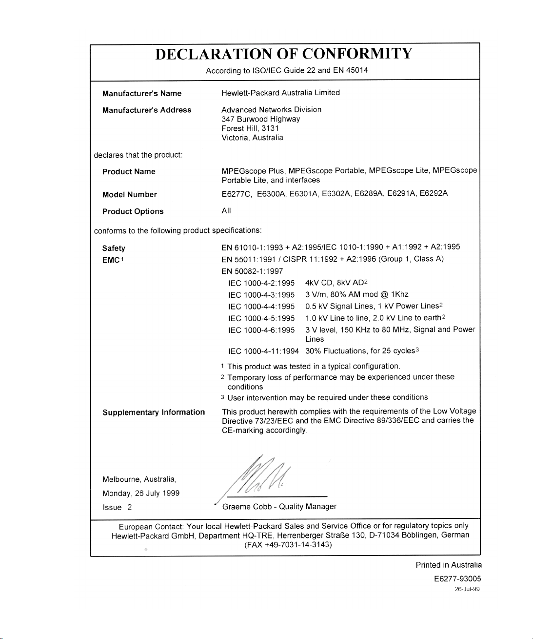
Certification
Agilent Technologies certifies that this
product met its published specifications at the
time of shipment from the factory. Agilent
Technologies further certifies that its
calibration measurements are traceable to the
United States National Institute of Standards
and Technology (formerly National Bureau of
Standards), to the extent allowed by that
organization’s calibration facility, and to the
calibration facilities of other International
Standards Organization members.
Additional Information for Test and
Measurement Equipment
To comply with EMC regulations, shielded
cables should be used on all appropriate
connections. Otherwise, the user has to
ensure that, under operating conditions, the
Radio Interference Limits are still met at the
border of the user's premises.
Warnings
The following general safety precautions
must be observed during all phases of
operation, service, and repair of this product.
Failure to comply with these precautions or
with specific warnings elsewhere in this
manual violates safety standards of design,
manufacture, and intended use of the
product. Agilent Technologies assumes no
liability for the customer’s failure to comply
with these requirements.
Ground the Equipment
Ground the Equipment: For safety, Class 1
Ground the EquipmentGround the Equipment
equipment (equipment having a protective
earth terminal), an uninterruptible safety
ground must be provided from the mains
power source to the product input wiring
terminals or supplied power cable. Before
operating the equipment, guard against
electric shock in case of fault by always using
the provided 3-conductor power cord to
connect the equipment to a grounded power
outlet.
DO NOT use in hazardous environments
DO NOT use in hazardous environments: Do
DO NOT use in hazardous environmentsDO NOT use in hazardous environments
not operate the product in an explosive
atmosphere or in the presence of flammable
gases or fumes. This product is designed for
indoor use only.
DO NOT use repaired fuses or short-circuited
DO NOT use repaired fuses or short-circuited
DO NOT use repaired fuses or short-circuited DO NOT use repaired fuses or short-circuited
fuse holders
fuse holders: For continued protection against
fuse holdersfuse holders
fire, replace line fuses only with fuses of the
same voltage and current rating and type.
Keep away from live circuits
Keep away from live circuits: Operating
Keep away from live circuitsKeep away from live circuits
personnel must not remove equipment covers
or shields. Procedures involving the removal
of covers and shields are for use by servicetrained personnel only. Under certain
conditions, dangerous voltages may exist
even with the equipment switched off. To
avoid dangerous electrical shock, DO NOT
perform procedures involving cover or shield
removal unless you are qualified to do so.
DO NOT operate damaged equipment
DO NOT operate damaged equipment:
DO NOT operate damaged equipmentDO NOT operate damaged equipment
Whenever it is possible that the safety
protection features built into this product
have been impaired, either through physical
damage, excessive moisture, or any other
reason, REMOVE POWER and do not use the
product until safe operation can be verified by
service-trained personnel. If necessary, return
the product to an Agilent Technologies Sales
and Service Office for service and repair to
ensure the safety features are maintained.
DO NOT substitute parts or modify
DO NOT substitute parts or modify
DO NOT substitute parts or modify DO NOT substitute parts or modify
equipment
equipment: Because of the danger of
equipmentequipment
introducing additional hazards, do not install
substitute parts or perform any unauthorized
modification to the product. Return the
product to an Agilent Technologies Sales and
Service Office for service and repair to ensure
features are maintained.
DO NOT clean with fluids
DO NOT clean with fluids: Doing so may
DO NOT clean with fluidsDO NOT clean with fluids
make the equipment unsafe for use. Power
down the equipment and disconnect the
power cord before cleaning. To clean, use a
soft dry cloth.
Safety Symbols
If you see this symbol on a product, you must
refer to the manuals for specific Warning or
Caution information to avoid personal injury
or damage to the product
Indicates the field wiring terminal that must
be connected to ground before operating the
equipment. Protects against electrical shock
in case of fault.
or
Frame or chassis ground terminal. Typically
connects to the equipment’s metal frame.
Alternating current (ac).
Direct current (dc).
Indicates hazardous voltages and potential for
electrical shock.
Indicates that antistatic precautions should be
taken.
This product complies with CSA requirement
CSA 22.2 No. 1010.1, NRTL/C, EN 610101:1993 + A2:1995/IEC 1010-1:1990 +
A1:1992 + A2:1995 Safety requirements for
electrical equipment for measurement,
control, and laboratory use.
Notice for European Community: This product
complies with the relevant European legal
Directives: EMC Directive 89/336/EEC and
Low Voltage Directive 73/23/EEC.
Das CE-Zeichen zeigt die Übereinstimmung
mit allen für das Produkt geltenden Direktiven
der Europäischen Union an.
ISM 1—A
This is the symbol for an Industrial, Scientific,
and Medical Group 1 Class A product.
iii
Page 4

Dieses Zeichen steht für ein Produkt der
Gruppe 1, Klasse A, für den Einsatz im
industriuellen, wissenschaftlichen und
medizinischen Bereich.
This product meets the requirements of the
Australian EMC Framework (AS/NZS
2064.1/2 for ISM:1A), enforced by the
Radiocommunications Act 1992.
WARNING
Calls attention to a procedure, practice, or
condition that could cause bodily injury or
death.
CAUTION
Calls attention to a procedure, practice, or
condition that could possibly cause damage to
equipment or permanent loss of data.
Certification
Agilent Technologies certifie que cet
instrument est conforme aux spécifications
publiées au moment de sa sortie d’usine.
Agilent Technologies atteste en outre qu’il est
possible de trouver référence à ses mesures
d’étalonnage auprès de l’organisme de
normalisation américain “United States
National Institute of Standards and
Technology” (auparavant National Bureau of
Standards), dans la mesure des possibilités
autorisées par cet organisme, et dans celles
autorisées par d’autres membres de
l’Organisation Internationale de
Normalisation.
Informations complémentaires
relatives à l ‘équipement de test et
de mesure
Conformément aux réglementations
concernant la compatibilité
électromagnétique, il convient d’utiliser des
câbles blindés sur toutes les connexions
appropriées. S’il n’emploie pas ce type de
câble, l’utilisateur doit vérifier qu’en condition
d’exploitation les interférences radio sont
encore acceptables à la limite de ses locaux.
Avertissement
Les précautions générales de sécurité ci-
dessous doivent être observées au cours de
toutes les phases d’exploitation, de
maintenance et de réparation de l’instrument.
Le non-respect de ces précautions ou
d’avertissements spécifiques cités ailleurs
dans le manuel entraîne la violation des
normes de sécurité relatives à la conception,
la fabrication et l’utilisation prévue de cet
instrument. Agilent Technologies n’assume
aucune responsabilité en cas de non-respect
de ces exigences.
Mise à la terre de l’équipement: en vue de
garantir la sécurité, pour l’équipement de
classe 1 (comportant une borne mise à la
terre de protection), une mise à la terre
permanente doit être assurée de la source
d’alimentation secteur aux bornes de câblage
d’entrée de l’instrument ou au câble
d’alimentation fourni. Avant d’utiliser
l’équipement, évitez les chocs électrostatiques
en cas de défaillance de l’instrument en
utilisant toujours le cordon d’alimentation 3
conducteurs fourni pour brancher
l’équipement à une prise de terre.
N’UTILISEZ PAS dans un environnement à
risque : N’utilisez pas l’instrument dans des
conditions de risques d’explosion ni en
présence de gaz ni d’émanations
inflammables. Cet instrument est conçu
exclusivement pour un usage intérieur.
N’UTILISEZ PAS de fusibles usagés ni de
porte-fusibles en court-circuit: Pour une
protection permanente contre le feu,
remplacez les fusibles uniquement par des
fusibles de même tension, de même calibre et
de même type.
Tenez vous à l’écart des circuits sous tension:
Le personnel d’exploitation ne doit pas retirer
les capots ni les blindages. Les procédures
impliquant ces manipulations doivent être
exécutées exclusivement par un personnel
formé à la maintenance. Dans certaines
conditions, des tensions dangereuses peuvent
être générées même lorsque l’équipement
n’est pas sous tension. Afin d’éviter tout
risque d’électrocution, N’EXÉCUTEZ PAS de
procédure nécessitant la manipulation des
capots et des blindages sans qualification à
cet effet.
N’UTILISEZ PAS d’équipement endommagé:
Si les caractéristiques de l’instrument
relatives à la sécurité ont été atteintes, que
ce soit en raison d’un dommage physique,
d’une humidité excessive, ou pour toute autre
cause, METTEZ L’EQUIPEMENT HORS
TENSION et ne l’utilisez plus jusqu’à ce que la
sécurité de son fonctionnement puisse être
vérifiée par un personnel formé à la
maintenance. Si nécessaire, retournez
l’instrument à un bureau commercial et de
service après-vente Agilent Technologies pour
le faire réparer et garantir ses caractéristiques
de sécurité.
NE REMPLACEZ PAS de pièce ni ne modifiez
l’équipement: En raison des risques
supplémentaires que cela implique, n’installez
pas de pièce de remplacement ni n’exécutez
aucune modification non autorisée sur
l’instrument. Retournez-le à un bureau
commercial et de service après-vente Agilent
Technologies pour le faire réparer et garantir
ses caractéristiques de sécurité.
NE NETTOYEZ PAS avec des produits
liquides: L’emploi de produits liquides peut
être risqué. Mettez l’équipement sous tension
et débranchez le cordon d’alimentation avant
le nettoyage. Utilisez un chiffon doux et sec.
Symboles de sécurité
Si vous apercevez ce symbole sur un
instrument, vous devez vous référer aux
manuels pour de plus amples informations
concernant les notes Avertissement et
Attention en vue d’éviter des blessures
corporelles ou des dommages à l’instrument.
Indique la borne de câblage qui doit être
connectée à la terre avant la mise en route de
l’équipement. Protège contre les
électrocutions en cas de défaillance de
l’instrument.
iv
Page 5
Borne de mise à la terre de cadre ou de
châssis. Connectée en principe au cadre
métallique de l’équipement.
ou
Dieses Zeichen steht für ein Produkt der
Gruppe 1, Klasse A, für den Einsatz im
industriuellen, wissenschaftlichen und
medizinischen Bereich.
Courant alternatif (ca).
Courant continu (cc).
Indique une tension dangereuse et des risques
d’électrocution.
Indique que des précautions anti-statiques
doivent être prises.
.
Cet instrument satisfait aux spécifications
CSA 22.2 No. 1010.1, NRTL/C, EN 610101:1993 + A2:1995/IEC 1010-1:1990 +
A1:1992 + A2:1995 en matière de sécurité
pour les équipements électriques de mesure,
de contrôle et de laboratoire.
Label européen: cet instrument est conforme
aux directives européennes suivantes: EMC
89/336/EEC et basse tension 73/23/EEC.
Das CE-Zeichen zeigt die Übereinstimmung
mit allen für das Produkt geltenden Direktiven
der Europäischen Union an.
Cet instrument est conforme aux
spécifications de l’Australian EMC Framework
(AS/NZS 2064.1/2 for ISM:1A), mises en
oeuvre par le Radiocommunications Act de
1992.
AVERTISSEMENT
AVERTISSEMENT
AVERTISSEMENTAVERTISSEMENT
Attire l’attention sur une procédure, pratique
ou condition comportant un risque de
blessure ou d’électrocution.
ATTENTION
ATTENTION
ATTENTIONATTENTION
Souligne qu’une procédure, pratique ou
condition peut entraîner des dommanges à
l’équipement ou la perte permanente de
données.
ISM 1—A
Ce symbole indique que l’instrument est un
instrument de type Industriel Scientifique et
Médical Groupe 1 Classe A.
v
Page 6

Page 7
Page 8

Page 9

Right
Contents
Introduction............................................................................................................................................... 1-1
top margin for modules
For More Information .............................................................................................................................. 1-3
How To Contact Us ................................................................................................................................. 1-4
body text drop
Getting Started ......................................................................................................................................... 2-1
Starting an MPEGscope Test Session ....................................................................................................... 2-2
Connecting to Interfaces.......................................................................................................................... 2-4
To Connect to the DVB-SPI Interface........................................................................................................ 2-6
To Connect to the ASI and Serial ECL (DHEI) Interface ......................................................................... 2-7
To Connect to the SMPTE 310M Interface................................................................................................ 2-9
To Connect to the ARIB Interface............................................................................................................ 2-10
Connecting an External Clock Source .................................................................................................... 2-11
Connecting an External Trigger Cable .................................................................................................... 2-12
Troubleshooting .................................................................................................................................... 2-13
Specifications ............................................................................................................................................A-1
Technical ................................................................................................................................................ A-2
General ................................................................................................................................................... A-5
Line Interface..........................................................................................................................................A-6
Reinstalling Software ............................................................................................................................. B-1
Reinstalling Software............................................................................................................................... B-2
Performing a System Backup ................................................................................................................... B-3
Performing a System Restore................................................................................................................... B-4
page inner margin
hanging column right margin
body text left margin
body text bottom margin
footer rulling line
Contents–1
footer text base line
outer margin for text and artwork
Page 10

Page 11

1
• For More Information 1-3
• How To Contact Us 1-4
Introduction
Page 12

Introduction
Welcome to MPEGscope, your new digital video test solution from
Hewlett-Packard. Combining real–time functionality with offline analysis of
MPEG, DVB, ATSC, ISDB, and private streams, MPEGscope can speed the
process of verifying and debugging digital video encoders, multiplexers, and
decoders. With MPEGscope, real–time analyzing begins automatically as soon
as you receive transport stream data. You can record, capture, store, play,
trigger on specific errors, and analyze data in a variety of ways. MPEGscope
features an intuitive, easy–to–use graphical user interface and online help
system to enable you to become quickly productive.
This guide contains information about setting up and connecting MPEGscope
to a system under test. It also cites technical specifications and applicable
digital video standards. For information about the computer in which
MPEGscope is contained, refer to the computer user’s guide shipped with
MPEGscope. For more information on the specific MPEGscope applications
you have purchased, refer to the MPEGscope online help and printed
materials shipped with your MPEGscope system.
CAUTION Hewlett–Packard does not guarantee that MPEGscope is compatible with
other Windows
problems caused by altering system configuration or initialization files.
®
applications or hardware. Hewlett-Packard will not support
1-2
Page 13
Introduction
For More Information
For More Information
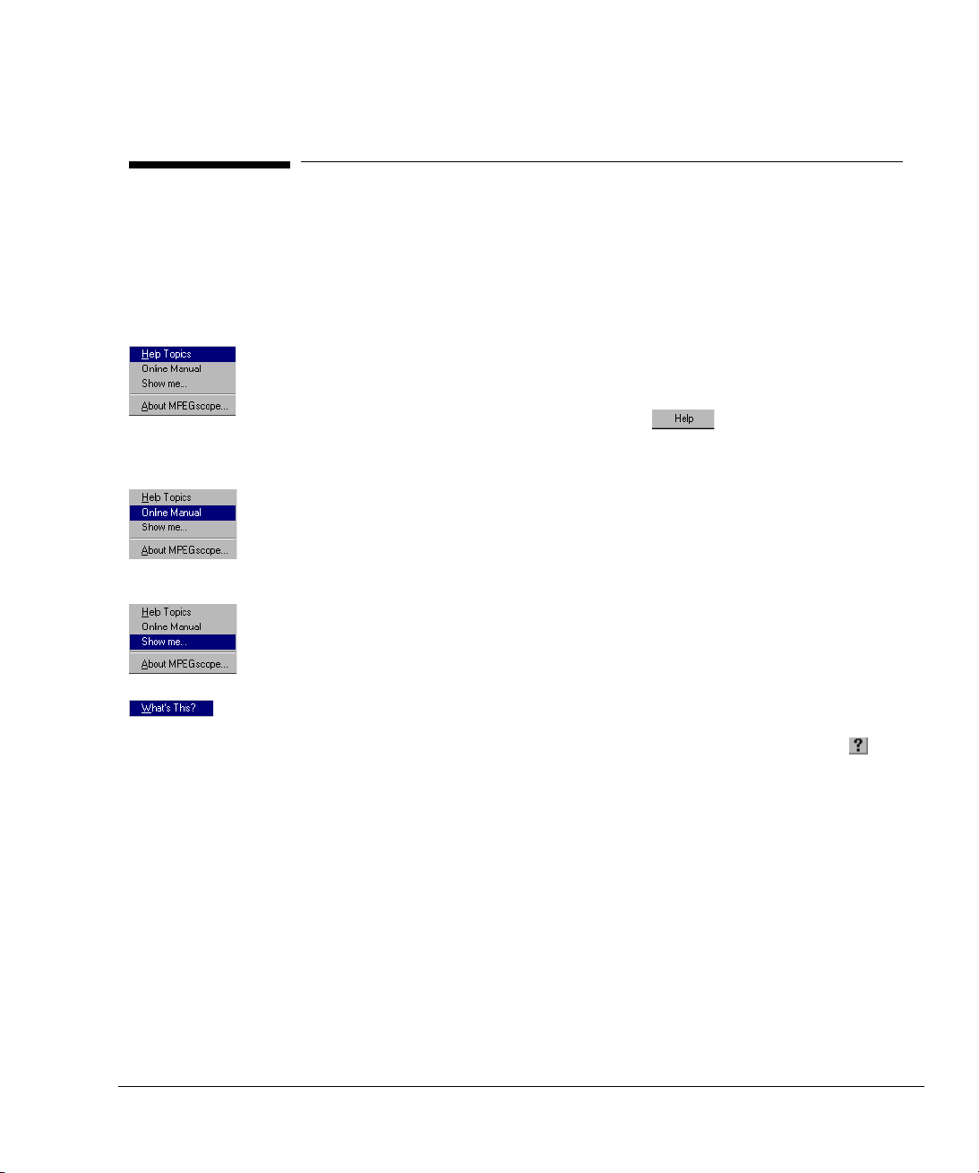
If you are using MPEGscope for the first time or performing a new task,
MPEGscope’s online help can guide you quickly to information you may need. You
can access help in the following ways.
• Select Help Topics from the Help menu to access the MPEGscope help
environment. You can then use Contents, Index, or Find to locate
information about a specific topic. You can also enter the help environment
from any dialog containing a Help button . Clicking on Help will
launch a help topic specific to that dialog.
• Select Online Manual from the Help menu to load the MPEGscope User’s
Guide in Acrobat
each MPEGscope application.
® Reader. This guide contains illustrated steps for testing with
• Select Show me... from the Help menu to view a list of self–paced tutorials to
lead you through typical test scenarios.
• Where indicated on the user interface, click the right mouse button over a field
or element in a dialog to obtain context–sensitive help on that item.
Alternatively, you can access context–sensitive help by clicking the button
in the upper right corner of a dialog, then clicking again over a dialog element.
1-3
Page 14

Introduction
How To Contact Us
How To Contact Us
If you need technical support, contact the support center in your region.
Location Telephone Email
North America 9780 South Meridian Blvd
Englewood, Colorado
USA 80112
Europe PO Box 999 Mail Stop 70
1180 AZ Amstelveen
The Netherlands
Germany, Austria, Switzerland +49-180-524-6333 messtechnik_support@agilent.com
Japan Hachioji Business Center
9-1 Takakura-Cho, Hachioji
Tokyo 192
Japan
Asia Pacific 438B Alexandra Road
Blk B, #05-08
Alexandra Technopark
Singapore 119968
Hong Kong 800-930-871
New Zealand 0800-44-5841
1-800-698-0061 Americas_Support@agilent.com
+31 20 547 9900
You may also call these
local numbers:
France +33-1-69294114 customer-care_tfo@agilent.com
UK +44-1344-366 666 test-measurement_uksupport@hp.com
Ireland +353-1-6158 222
Italy +39-02-92 12 22 41 agilent_direct@agilent.com
0120-421-345 mac_support@agilent.com
1800-274-4554
You may also call these
local toll-free numbers:
Australia 1800-143-243
China 10800-650-0021
India 000-6517-MTF-278-1596
Indonesia 001-800-65-7340
Japan 0120-421-345
Korea 080-999-1500
Malaysia 1800-80-1454
Philippines 1800-1-651-0170
Taiwan 0080-65-1317
Thailand 001-800-65-6206
ots-europe@agilent.com
asia_ots@agilent.com
1-4
Page 15

2
• Starting an MPEGscope Test Session 2-2
• Connecting to Interfaces 2-4
• Connecting an External Clock Source 2-11
• Connecting an External Trigger Cable 2-12
• Troubleshooting 2-13
Getting Started
Page 16

Getting Started
Starting an MPEGscope Test Session
This section leads you quickly through the necessary steps to begin testing
with MPEGscope. You can find more detailed information in the guides
specified below.
Set up MPEGscope
1
and connect the
keyboard, mouse, and
monitor.
Power on
2
MPEGscope. The
test software will
start automatically.
Computer user’s guide (for
instructions on setting up
and using the computer in
which your MPEGscope is
installed)
Microsoft NT® user’s guide
(for instructions on setting
up and using Windows
®
).
Note MPEGscope comes with all software pre-installed. If you need to reinstall the
software, refer to Appendix B, “Reinstalling Software”.
2-2
Page 17

Getting Started
Starting an MPEGscope Test Session
Connect MPEGscope
3
to the system under
“Connecting to Interfaces”,
page 2–4.
test.
CAUTION If you experience a problem during setup, refer to “Troubleshooting”, page 2–13,
for instructions. Do not remove the cover or handle any MPEGscope hardware
unless advised to do so by your HP customer support representative. Please
disregard any instructions in your PC user’s guide directing you to check or install
components inside your PC. Interfering with MPEGscope hardware may invalidate
your warranty.
CAUTION To ensure adequate ventilation, do not cover or obstruct vent holes. Overheated
equipment can produce unpredictable measurement results.
2-3
Page 18

Getting Started
Connecting to Interfaces
Connecting to Interfaces
MPEGscope comes equipped with a DVB-SPI (Synchronous Parallel Interface) on
the main MPEGscope board, and may also have another interface installed if you
have purchased an optional interface. The following sections explain how to
connect your system under test to the MPEGscope interfaces.
The MPEGscope interface cards are positioned differently depending on the
model of computer. The illustration below shows the slot positions for both the PC
and portable models.
MPEGscope Plus (E6277C) and MPEGscope Lite (E6301A)
(on back of computer)
Video card
PCI LAN card
DVB-SPI interface (main card)
Optional interface
Real-time Analyzer card*
(Empty)
*This slot is blank for the “Lite” versions.
MPEGscope Portable (E6300) and Portable Lite (E6302A)
(on side of computer)
Real-time Analyzer card*
Optional interface
DVB-SPI interface (main board)
SCSI card
Video card
2-4
Page 19

Getting Started
Connecting to Interfaces
.
CAUTION: Electrostatic Discharge (ESD)
All connectors on MPEGscope and the IEEE 1394 interface are susceptible to
electrostatic discharge. Take the necessary anti-static precautions to minimize
electrostatic damage.
WARNING: Shock Hazards
• Be aware of shock hazards when connecting equipment.
• Use the supplied power adapter which can handle the required loads and protect
you from electrical shock.
• Do not defeat the purpose of MPEGscope’s power cord ground, and do not block
access to the power cord or switch, in case you need to disconnect power in an
emergency.
2-5
Page 20

Getting Started
SPI I
Connecting to Interfaces
To Connect to the DVB-SPI Interface
nterface
The DVB-SPI (Synchronous Parallel Interface) includes two adapter cables that
™
adapt the SPI interface’s AMPLIMITE
26-pin connectors to DVB-standard DB-25
connectors.
DVB–SPI Tx DVB–SPI Rx
Connect the output line to
2
the DVB PI OUT port using
the other adapter cable.
EXT CLK IN
Connect the input line to
1
the DVB PI IN port using
one of the adapter cables.
2-6
Page 21

ASI I
nterface
Getting Started
Connecting to Interfaces
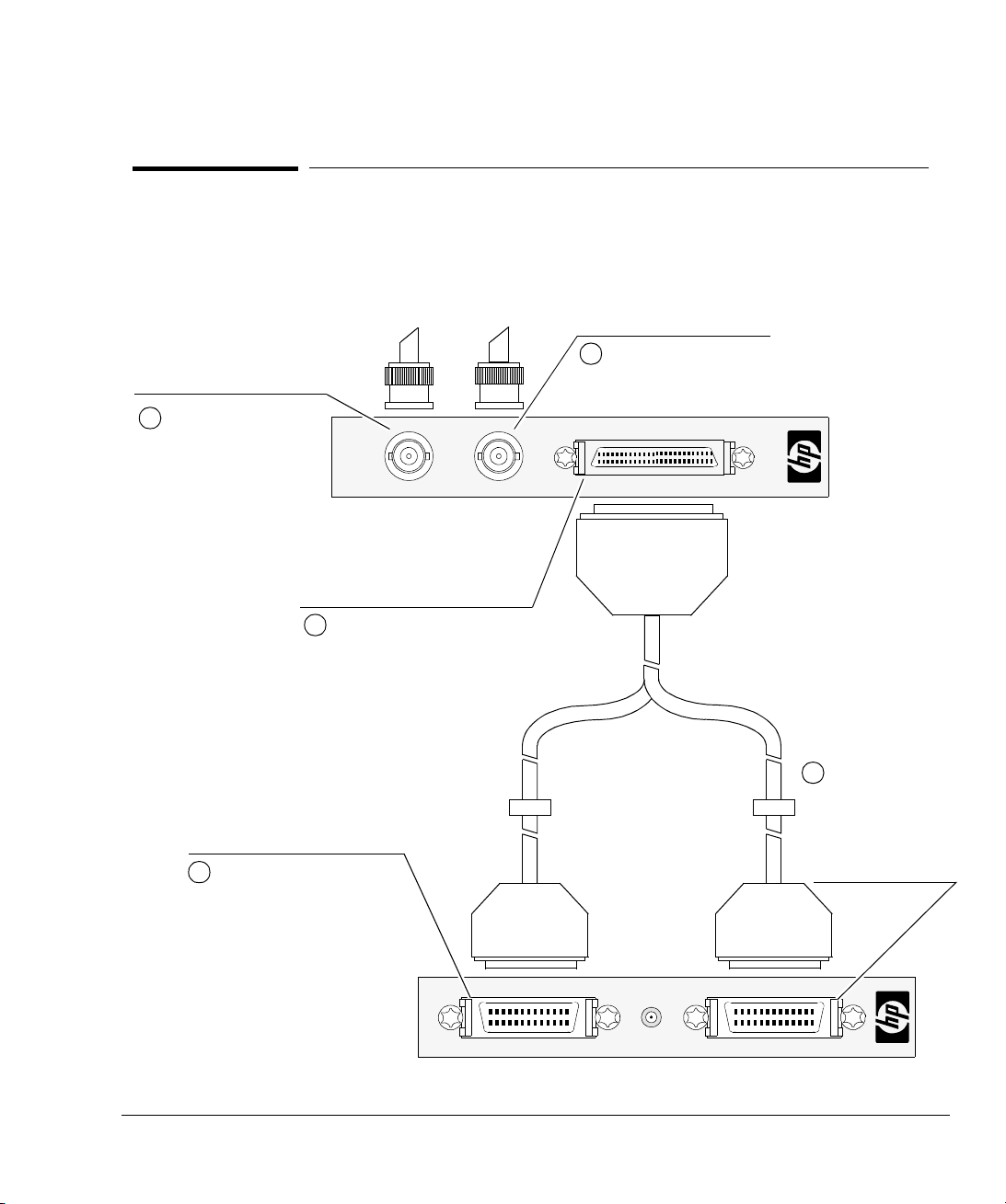
To Connect to the ASI and Serial ECL (DHEI) Interface
The ASI (Asynchronous Serial Interface) and Serial ECL (Digital Head End
Interface) includes two blue impedance converters for the ASI interface’s M2S
mode and a DHEI Expansion In/Out Y-Adapter cable for the DHEI interface.
M2S Mode
E6277
Connect the output line to
2
the ASI OUT port.
E6277
Connect the BNC connector of
2
the transmitter impedance
converter to the ASI OUT port.
The transmitter impedance
converter has a push–on SMB
connector.
ASI OUT
ASI OUT
ASI IN
Connect the input line to
1
the ASI IN port.
ASI IN
Connect the BNC connector
1
of the receiver impedance
converter to the ASI IN
port.
The receiver impedance
converter has a threaded SMA
connector.
Connect the SMB connector on the
4
transmitter impedance converter to
the SMB connector on the output
line.
Connect the SMA connector on
3
the receiver impedance
converter to the SMA connector
on the input line.
2-7
Page 22

Getting Started
DHEI I
Connecting to Interfaces
nterface
E6277
ASI OUT
Connect the single DB–25 male
1
ASI IN
connector on one end of the DHEI cable
to the MPEGscope DHEI port.
2-8
EXP IN
EXP OUT
MPEGscope DHEI
2
Connect the AMPLIMITE
TM
HD–22
26–pin male connector (labelled EXP
IN) on the other end of the DHEI cable
to the DHEI Expansion In line of your
system under test.
3
Connect the AMPLIMITE
TM
HD–22
26–pin male connector (labelled EXP
OUT) on the other end of the DHEI
cable to the DHEI Expansion Out line of
your system under test.
Page 23
SMPTE 310M I
nterface
Connect the output line to
1
your system under test to
the SMPTE OUT port.
Getting Started
Connecting to Interfaces
To Connect to the SMPTE 310M Interface
The SMPTE 310M interface is a serial-to-parallel converter for the DVB-SPI
interface. It includes a DVB-SPI Y-Adapter cable to connect the SMPTE 310M
interface to the SPI interface.
Connect the input line from
2
your system under test to
the SMPTE IN port.
SMPTE 310M
OUT
Connect the single SCSI 50-pin
3
connector on one end of the
DVB-SPI Y-Adapter cable to the
SMPTE DVB-SPI IN/OUT port.
IN
DVB - SPI IN/OUT
E6292A
Connect the SCSI 26-pin
4
male connector labelled SPI
Rx on the other end of the
DVB-SPI Y-Adapter cable to
the SPI interface DVB-SPI
Rx port.
Connect the other
5
SCSI 26-pin male
connector labelled
SPI Tx to the SPI
interface DVB-SPI
Tx port.
EXT CLK IN
DVB–SPI TxDVB–SPI Rx
2-9
Page 24

Getting Started
Connecting to Interfaces
To Connect to the ARIB Interface
The ARIB (Association of Radio Industries and Businesses) interface is an 8-bit
parallel TTL interface. It includes an ARIB IN cable and a DVB-SPI OUT cable to
connect the ARIB interface to the SPI interface.
ARIB Line Interface
Connect the E6289-61602 DVB-SPI
1
ADAPTER CABLE to the DVB SPI IN
port on the MPEGscope Main Board.
E6289A
DVB - SPI OUT ARIB IN
ARIB IN
DVB - SPI OUT
2-10
Connect the DVB-SPI
2
ADAPTER CABLE to the
DVB - SPI OUT port
(P/N E6289-61602).
Connect the input line
3
to the ARIB IN port
(P/N E6289-61601).
Page 25

Getting Started
Connecting an External Clock Source
Connecting an External Clock Source
You can use an external clock to synchronize the MPEGscope transmitter to the
network. You can also use a 27 MHz external clock as an analysis reference for the
Real–time Analyzer.
E
E
E
E
X
DVB–SPI Tx DVB–SPI Rx
X
X
X
T
T
T
T
C
C
C
C
L
L
L
L
K
K
K
K
I
I
I
I
N
N
N
N
Connect an external transmit clock
source to the SMB connector on the
SPI interface.
Note: MPEGscope is able to use
this external clock source
when transmitting from any
interface, not just the SPI
interface.
Sarnoff
2
2
2
2
R
R
R
R
I
I
I
I
7
7
n
n
7
7
n
n
e
e
e
e
M
M
p
p
M
M
p
p
f
f
f
f
u
u
u
u
C
C
C
C
H
H
H
H
t
t
t
t
l
l
l
l
k
k
z
z
k
k
z
z
Connect an external 27 MHz TTL
clock source to the SMB
connector on the Real–time
Analyzer.
The EXT CLK IN SMB connector accepts a 1 V p–p unbalanced signal input,
terminating with 50 ohms. The 27 MHZ REF CLK SMB connector accepts a TTL
input. It has low impedance to ground when the unit is turned off.
Note For optimum performance, the total length of the external clock cable should not
exceed three meters in length (approximately 10 feet).
2-11
Page 26

Connecting an External Trigger Cable
You can use a trigger cable with a 25-pin D-type male connector to connect your
external equipment to MPEGscope’s parallel port. The illustration below shows
MPEGscope’s parallel printer port female external pin layout.
Trigger Type:
TRIG IN
: active low, edge-sensitive
TRIG OUT
: active high, ~10 ms pulse width
25
Ground (pin 19)
13
TRIG IN (pin 10)
DB-25 connecto r
Parallel
Connect your external equipment
14
TRIG OUT (pin 2)
1
to MPEGscope’s parallel port using
a cable with a 25-pin D-type male
connector.
Note Before you can send or receive an external trigger, you must also configure
MPEGscope software from the Recorder/Player’s Record Setup dialog, then shut
down the default NT parallel port drivers and start the HP parallel port driver
from the Windows
® NT Control Panel. Press the Help button from the Record
Setup dialog for instructions.
For more information on configuring MPEGscope software to send or receive an
external trigger, refer to the MPEGscope online help system. Press the Tips
button at the MPEGscope Launch Pad, select the Index tab, and type “triggers”
to see the list of relevant topics.
Page 27

Troubleshooting
This section lists some problems that may occur during initial MPEGscope setup.
Symptom Suggested Action
Getting Started
Troubleshooting
Nothing happens when I
press the power button.
The MPEGscope
application doesn’t load
when I power up the
machine.
MPEGscope has crashed
and is displaying the blue
“crash dump” screen.
When I try to reboot after
getting the blue “crash
dump” screen, I get a
system disk error.
Ensure that all cables and power cords are firmly plugged in and that you have correctly followed the setup
instructions in your PC user’s guide. If your machine still does not start, contact your Hewlett-Packard
customer support representative who will advise you further. Do not attempt to reinstall or configure the
®
Windows
• Check that MPEGscope is one of the program folders in your Windows
system software unless your customer support representative instructs you to.
®
Start menu. If the MPEGscope
folder is there, try to load the application by selecting the MPEGscope program name. If this works, refer
to Windows
®
online help to add the MPEGscope folder to your Startup folder.
• If the MPEGscope folder is not there, check that the MPEGscope application files are installed on the hard
drive. If you need to reinstall the software, refer to Appendix B, “Reinstalling Software”.
• If these measures do not solve the problem, contact your Hewlett-Packard customer support
representative.
• Press the Reset button and hold down for a few seconds to make sure that MPEGscope resets.
DO NOT POWER OFF THE PC, OTHERWISE THE MASTER BOOT RECORD ON THE SYSTEM DISK MAY
BECOME CORRUPTED.
You can help avoid blue screen problems by ensuring that all hard disk activity has stopped before you log
in. When the login screen appears, wait until the hard disk light on the front of your PC has completely
stopped flickering.
The master boot record on the system disk may be corrupt. You can repair it with the Windows
®
NT install
disks and emergency repair disk shipped with MPEGscope, as follows:
1 Boot MPEGscope using the Windows
screen and insert Windows
®
®
NT Setup Disk 1. Follow the prompts at the bottom of the
NT Setup Disk 2 when directed.
2When the Welcome to Setup screen is displayed, press R to start the system disk repair. After doing
this, the following menu appears:
[X] Inspect registry files
[X] Inspect startup environment
[X] Verify Windows NT system files
[X] Inspect boot sector
Continue (perform selected tasks)
2-13
Page 28

Getting Started
Troubleshooting
Symptom Suggested Action
3 Clear the X’s from all the options except Inspect boot sector, then select Continue (perform
selected tasks) and press Enter.
4 Insert Windows
Disk when prompted.
5 The boot sector repair will take a few seconds. When the message on the screen indicates the repair is
complete, remove all diskettes from the drive and restart the system.
6 After the system restarts, run the Check Disk (chkdsk) utility to determine if any problems remain with
your system disk, as follows:
a) Launch the Disk Administrator from the Start/Programs/Administrative Tools (Common)
menu.
b) From the Disk Administrator, click anywhere in the Disk 0 field to select C: drive.
c) From the Tools menu, select Properties, then select the Tools tab.
d) From the Error–checking box, select the Check Now button.
e) From the Check Disk C:\ dialog, select both Check Disk options—Automatically fix file
system errors and Scan for and attempt recovery of bad sectors.
f) Select Start.
g) An information window is displayed which indicates that the Check Disk process cannot be
performed immediately because the utility cannot obtain exclusive access to the drive.
h) Shut down and restart MPEGscope. Check Disk will execute during the system startup.
®
NT Setup Disk 3 when directed then insert the MPEGscope Plus Windows® NT Repair
Click Yes to proceed.
Click OK to close the Properties window.
Close the Disk Administrator window.
CAUTION Do not remove the cover or handle any MPEGscope hardware unless advised
to do so by your HP customer support representative. Please disregard any
instructions in your PC user’s guide directing you to check or install components
inside your PC. Interfering with MPEGscope hardware may invalidate your
warranty.
2-14
Page 29

A
• Technical A-2
• General A-5
• Line Interface A-6
Specifications
Page 30

Specifications
Technical
Portions of the following standards are relevant to MPEGscope. You should be familiar with these
standards before using this guide.
ISO/IEC standards • ISO/IEC 11172-2:1999 Information technology—Coding of moving pictures and associated audio for
digital storage media at up to about 1,5 Mbit/s—Part 2: Video
• ISO/IEC 11172-3:1996 Information technology—Coding of moving pictures and associated audio for
digital storage media at up to about 1,5 Mbit/s—Part 3: Audio
• ISO/IEC 13818-1:2000 Information technology—Generic coding of moving pictures and associated
audio information—Part 1: Systems
• ISO/IEC 13818-2:2000 Information technology—Generic coding of moving pictures and associated
audio information—Part 2: Video
• ISO/IEC 13818-3:1998 Information technology—Generic coding of moving pictures and associated
audio information—Part 3: Audio
• ISO/IEC 13818-4:1998 Information technology—Generic coding of moving pictures and associated
audio information—Part 4: Compliance testing
• ISO/IEC 13813-6:1999 Information technology—Generic coding of moving pictures and associated
audio information—Part 6: Extensions for DSM-CC
• Amendment 1 to ISO/IEC 13818-6:1999 Additions to support Data Broadcasting
• Amendment 2 to ISO/IEC 13818-6:1999 Additions to support Synchronized Download Services,
Opportunistic Data Services and Resource Announcement in Broadcast and Interactive Service
• ISO/IEC 13913-7:1998 Information technology—Generic coding of moving pictures and associated
audio information—Part 7: Advanced Audio Coding (AAC)
• ISO/IEC 13818-9:1996 Information technology—Generic coding of moving pictures and associated
audio information—Part 9: Extensions for real time interface for system decoders
DVB standards • ETR 154:1997 Digital Video Broadcasting (DVB); Implementation guidelines for the use of MPEG-2
Systems, Video and Audio in satellite, cable and terrestial broadcasting applications
• ETR 162:1995 Digital broadcasting systems for television, sound and data services; Allocation of
Service Information (SI) codes for Digital Video Broadcasting (DVB) systems
A-2
Page 31

• ETR 211:1997 Digital Video Broadcasting (DVB); Guidelines on implementation and usage of DVB
service information
• ETR 290:1997 Digital Video Broadcasting (DVB); Measurement guidelines for DVB systems
• EN 300 468 v1.3.1:1998-02 Digital Video Broadcasting (DVB); Specification for Service Information
(SI) in DVB systems
• EN 300 472 v1.2.2:1997-08 Specification for conveying ITU-R System B Teletext in DVB bitstreams
• Draft EN 301 192 v1.2.1:1999-01 Digital Video Broadcasting (DVB); DVB specification for data
broadcasting
• TR 101 202 v1.1.1:1999-02 Digital Video Broadcasting (DVB); Implementation guidelines for Data
Broadcasting
• TS 101 191 v1.2.1:1997 Digital Video Broadcasting (DVB); DVB mega-frame for Single Frequency
Network (SFN) synchronization
ATSC standards • ATSC A/52:1995 Digital Audio Compression Standard (AC-3)
• ATSC A/53:1995 ATSC Digital Television Standard
Specifications
Technical
• Draft Technical Corrigendum No. 1 to: ATSC Digital Television Standard Doc. A/53
• ATSC A/54:1995 Guide to the Use of the ATSC Digital Television Standard
• ATSC A/57:1996 Program/ Episode/ Version Identification—ATSC standard
• ATSC A/63:1997 Standard for Coding 25/50 Hz Video
• ATSC A/65:1997 Program and System Information Protocol for Terrestrial Broadcast and Cable—
ATSC standard
• ATSC A/66:1999 Technical Corrigendum No. 1 to ATSC Standard: Program and System Information
Protocol for Terrestial Broadcast and Cable Doc. A/65
• ATSC A/67:1999 Amendment No. 1 to ATSC Standard: Program and System Information Protocol
for Terrestial Broadcast and Cable Doc. A/65
• Draft ATSC T3/S13 Doc. 101 Rev. 1.2:1999 ATSC Data Broadcast Specification
RFCs • IETF RFC 791: Internet Protocol
• IETF RFC 768: User Datagram Protocol
• IETF RFC 793: Transmission Control Protocol
ARIB standards • ARIB STD-B1, Version 1.3
A-3
Page 32

Specifications
Technical
• ARIB STD-B10, Version 1.2
• ARIB STD-B15, Version 1.0
• ARIB STD-B20, Version 1.1
• ARIB STD-B24, Version 1.0
Interface standards • TIA/EIA-644:1995 Electrical characteristics of low voltage differential signalling (LVDS) interface
circuits
• EN 50083–9 Interfaces for CATV/SMATV Headends and similar Professional Equipment
• 016–0002–001: Application Note 0002: Revision A: Using the DiviCom M2S Interface, DiviCom Inc.
• SCTE DVS/110:4 Sept 1997: Response to SCTE DVS CFI (DVS/089R1): Cable Headend and
Distribution Systems, Section 3.2: Digital Headend Expansion Interface (DHEI)
• Proposed SMPTE Standard for Television—Synchronous Serial Interface fo MPEG-2 Digital Transport
Stream, September, 1998
• IEEE Std 1394-1995: IEEE Standard for a High Performance Serial Bus, IEEE Computer Society, 12
December 1995
A-4
• IEEE Std. 1394a-2000: IEEE Standard for a High Performance Serial Bus, IEEE Computer Society,
2000
• ISO/IEC 61883-1 1998-02: Consumer audio/video equipment—Digital interface—Part 1: General,
First edition
• ISO/IEC 61883-4 1998-02: Consumer audio/video equipment—Digital interface—Part 4: MPEG-2 TS
data transmission, International Electrotechnical Commission, First edition
• AV/C Digital Interface Command Set General Specification, 1394 Trade Association, Version 3.0,
April 15, 1998
• Enhancements to the AV/C General Specification 3.0, 1394 Trade Association, Version 1.0, January
26, 1998
• AV/C Digital Interface Command Set VCR Subunit Specification, 1394 Trade Association, Version
2.0.1, January 5, 1998
• AV/C Tuner Model and Command Set, 1394 Trade Association, Version 1.0, April 15, 1998
• AV/C Tuner Broadcast System Specification—Digital Video Broadcast (DVB), 1394 Trade Association,
Version 1.0, April 15, 1998
• EIA-775: DTV 1394 Interface Specification, Electronic Industries Alliance, December, 1998
Page 33

General
Performance • Transmitting from disk: • Minimum: 250 Kb/s
• Maximum: 85 Mb/s for E6277B, E6277C, E6300A, E6301A,
E6302A
60 Mb/s for E6277A
• Recording to disk: Up to 85 Mb/s for E6277B, E6277C, E6300A, E6301A, E6302A
Up to 60 Mb/s for E6277A
• Real-time analysis: 42.5 Mb/s (including null packets) with the restriction that the PSI and
SI table rates are less than 2 Mb/s
Capacity • Multi–program transport stream (MPTS) can be recorded or transmitted
• Real–time measurements are performed on one transport stream
• Real–time measurements can occur simultaneously with recording to disk or transferring from disk
• up to 9 (or 18) GB of data can be recorded, depending on size of streaming disk. (18 GB streaming
disk is Option E6277B Opt 518)
Specifications
General
Bus type PCI/ISA
External clock • 50 Ω nominal, terminated to ground
• Level: 1 V p—p unbalanced
• Frequency range: 33 kHz to 66 MHz
• Connector: SMB
• Duty cycle: better than 55/45%
• Can be used by the transmit ports
27 MHz reference
clock
• High impedance
• Level: TTL
• Connector: SMB
• Duty cycle: better than 55/45%
• Can be used as a measurement reference for the real–time analyzer
A-5
Page 34

Specifications
Line Interface
Line Interface
Port Configurations
SPI ASI M2S DHEI
Type 8–bit parallel serial serial serial
Maximum line rate 108 Mb/s 216 Mb/s 216 Mb/s 40 Mb/s
Timestamps Packet timestamp clock:
10 MHz +/- 5 ppm
Resolution of timestamp
clock: 100 ns
Packet timestamp
sampling is accurate to
within +/- 1 timestamp
clock period between
consecutive packets
Electrical Spec EIA/TIA-644 (LVDS) 75 Ω coax 50 Ω coax Balanced ECL
Connector Type DB-25 (through adapter) BNC SMA/SMB
Standard EN 50083–9
“Interfaces for
CATV/SMATV Headends
and similar Professional
Equipment”
Part Number N/A ASI and Serial ECL (DHEI) interface: E6291A
Packet timestamp clock:
33 MHz +/- 5 ppm
Resolution of timestamp
clock: 30 ns
Packet timestamp
sampling is accurate to
within +/- 1 timestamp
clock period between
consecutive packets
EN 50083–9
“Interfaces for
CATV/SMATV Headends
and similar Professional
Equipment”
Packet timestamp clock:
33 MHz +/- 5 ppm
Resolution of timestamp
clock: 30 ns
Packet timestamp
sampling is accurate to
within +/- 1 timestamp
clock period between
consecutive packets
(through adapter)
“Using the DiviCom M2S
Interface”—DiviCom
Application Note 0002
Packet timestamp clock:
33 MHz +/- 5 ppm
Resolution of timestamp
clock: 30 ns
Packet timestamp
sampling is accurate to
within +/- 1 timestamp
clock period between
consecutive packets
DB-25
SCTE DVS/110
4 September 1997
Response to SCTE DVS
CFI (DVS/089R1):
Cable Headend and
Distribution Systems
WARNING To ensure the Electromagnetic Compatibility (EMC) of MPEGscope, use shielded
cables on all interfaces.
A-6
Page 35

SMPTE 310M ARIB
Type Biphase mark Synchronous 8-bit parallel
Specifications
Line Interface
Maximum line rate 40 Mb/s
(Minimum line rate is
16 Mb/s)
Timestamps Packet timestamp clock:
10 MHz +/- 5 ppm
Resolution of timestamp
clock: 100 ns
Packet timestamp sampling
is accurate to within +/- 1
timestamp clock period
between consecutive
packets
42.5 Mb/s
(Receive clock rate is 25 kHz
to 12.25 MHz)
Packet timestamp clock:
10 MHz +/- 5 ppm
Resolution of timestamp
clock: 100 ns
Packet timestamp sampling
is accurate to within +/- 1
timestamp clock period
between consecutive
packets
Electrical Spec 800 mV pp (nominal) TTL levels
Connector Type 75 Ω BNC 20 pin Mini-SCSI
Standard SMPTE 310M Standard,
ARIB STD-B1, Version 1.1
Sept. 98
Part Number E6292A E6289A
WARNING To ensure the Electromagnetic Compatibility (EMC) of MPEGscope, use shielded
cables on all interfaces.
A-7
Page 36

Specifications
Line Interface
Pinouts
Pin SPI 26
1 Clock B Clock A — PROTGND PROTGND PROTGND
2 Clock A GND — PCLKI+ SENSEOR SENSEIR
3 Data 7 B Data 7 A — PDATAI+ PSYNCO– PSYNCI–
4 Data 7 A Data 6 A — PSYNCI+ PDATAO– PDATAI–
114
5 Data 5 B Data 5 A — SENSEIL PCLKO+ PCLKI+
6 Data 5 A Data 4 A — REFCLKI+ PCLKO– PCLKI–
13 26
7 Data 3 B Data 3 A — SIGGND REFCLKO+ REFCLKI+
8 Data 3 A Data 2 A — PCLKO+ REFCLKO– REFCLKI–
9 Data 1 B Data 1 A — PDATAO+ SIGGND SIGGND
AMPLIMITE™26-pin
female connector on
MPEGscope SPI port
10 Data 1 A Data 0 A — PSYNCO+ ——
11 DVALID B DVALID A — SENSEOL SENSEOL SENSEIL
12 DVALID A PSYNC A — REFCLKO+ PSYNCO+ PSYNCI+
13 GND GND Serial– SIGGND PDATAO+ PDATAI+
14 GND Clock B — SIGGND ——
15 GND GND — PCLKI–— —
16 Data 6 B Data 7 B — PDATAI–— —
1
14
17 Data 6 A Data 6 B — PSYNCI–— —
18 Data 4 B Data 5 B — SENSEIR ——
19 Data 4 A Data 4 B — REFCLKI–— —
13
25
20 Data 2 B Data 3 B — SIGGND ——
21 Data 2 A Data 2 B — PCLKO–— —
DB-25 female connector on
SPI adapter cable
22 Data 0 B Data 1 B — PDATAO–— —
23 Data 0 A Data 0 B — PSYNCO–— —
24 PSYNC B DVALID B — SENSEOR ——
25 PSYNC A PSYNC B — REFCLKO–— —
26 GND — Serial+ —— —
a. AMPLIMITE™26-pin connector
b. DB-25 connector
c. SMA/SMB connector
d. DB-25 connector
e.AMPLIMITE
(a)
™
HD- 22 26-pin connector
SPI 25
(b)
M2S
(c)
DHEI
(d)
DHEI
EXP IN
(e)
DHEI
EXP OUT
(e)
1
13
MPEGscope DHEI port
14
25
DB-25 female
connector on
18
9
1
26
19
10
AMPLIMITE™ HD- 22
26-pin connector on
DHEI cable
A-8
Page 37

Pinouts
Specifications
Line Interface
1
13
DB-25 female connector on
DVB-ARIB OUT port
1
10
Connector on DVB-ARIB IN
14
25
11
20
port
Pin ARIB
(a)
1 Data TPD7 (MSB)
2 Data TPD6
3 Data TPD5
4 Data TPD4
5 Data TPD3
6 Data TPD2
7 Data TPD1
8 Data TPD0 (LSB)
9 BCK Byte Clock
10 PSY Packet Start
11 Reserved (Out)
12 SLOCK Synch
13 SEN Activate
14 Open - Not Connected
15 GND Signal
16 GND Signal
17 GND Signal
18 Reserved (In)
19 Reserved (In)
20 Reserved (Out)
21 —
22 —
23 —
24 —
25 —
26
a. ARIB IN connector
A-9
Page 38

Page 39

B
• Reinstalling Software B-2
• Performing a System Backup B-3
• Performing a System Restore B-4
Reinstalling Software
Page 40

Reinstalling Software
MPEGscope comes with all the software pre–installed. However, an
installation disk is included in case you need to reinstall the software for any
reason. This appendix explains how to reinstall software, perform a system
backup, and restore your system.
Reinstalling Software
This process takes five to ten minutes.
1 If you have lost the license file backup disk shipped with your
MPEGscope, back up your permanent license file before installing
software by copying the file C:\HP-Apps\FLEXlm\licence.dat to a
floppy disk.
2 Insert the MPEGscope installation CD into the CD-ROM drive.
3 Launch the installation program by double-clicking on D:\Setup.exe from
the Windows
4 Follow the prompts in the installation dialogs. Accept the defaults each
time you are prompted for a choice.
5 When the installation program has finished copying MPEGscope files, the
PC will automatically shut down. Instead of resetting the PC, turn off the
power with the power switch.
6 Turn the power back on and log in. When the PC reboots, firmware is
automatically downloaded to the MPEGscope main card.
IMPORTANT Occasionally a blue “crash dump” screen may occur if you log in quickly. To
avoid the problem, do not log in until the hard disk light on the front of your
PC has stopped flickering and all disk activity has stopped. If a blue screen
occurs, press the
sure that MPEGscope resets.
7 Follow the prompts to shut down the PC once more. Use the power switch
to turn off the PC when Windows
8 Turn the power switch back on and remove the MPEGscope installation
CD from the CD-ROM drive.
NT Explorer window.
reset button and hold it down for a few seconds to make
NT indicates it is safe to do so.
B-2
Page 41

Reinstalling Software
Performing a System Backup
Performing a System Backup
If you have purchased the optional 12/24 GB DAT drive, you can perform a system
backup as follows:
®
1 Start the Windows
• Click the Start button on the task bar.
• Select Programs, Administrative Tools (Common), Backup.
2 Expand the Drives window.
3 Enable the check boxes to the left of drives C: and E: to select them.
4 Click the Backup button.
5 From the Backup Information window, select Backup Local Registry, then
click OK to start the backup procedure. Progress will be displayed in a Backup
Status window. During the procedure, at least one file will be skipped (a
temporary file used by the backup program). The procedure takes at least six
minutes to complete, and possibly longer.
NT Backup program:
6 When the Backup Status window indicates that the procedure is complete,
close all Backup windows, eject the cassette, and store it in a safe place.
B-3
Page 42

Reinstalling Software
Performing a System Restore
Performing a System Restore
After backing up the system drive to the optional 12/24 GB DAT drive, you can
restore it as follows:
1 Start the Windows
2 Expand the Tape s window.
3 Double click the C:MPEGSCOPE entry. The tape program will create an
4 Click the Restore button.
5 The Restore Information window should display Restore to
®
NT Backup program:
• Click the Start button on the task bar.
• Select Programs, Administrative Tools (Common), Backup.
inventory list of the files on the tape.
Drive=C:MPEGSCOPE. Select Restore Local Registry and Restore File
Permissions, then click OK.
B-4
6 Progress will be displayed in a Restore Status window. Early in the procedure,
a Confirm File Replace warning message will be displayed. Select Yes to All
to proceed.
7 When the procedure is complete, shut down and restart the PC.
Page 43

Right
Index
Contents, Figures, Tables
A
ARIB line interface
connecting to,2-10
ASI and Serial ECL (DHEI) interface card
E6277B,2-4
E6300A, 2-4
ASI line interface
connecting to,2-7
connector type, A-6, A-7
pinouts,A-8
port configurations,A-6
Asynchronous Serial Interface, see ASI line interface
B
backing up software,B-3
bus,A-5
C
cables
DHEI line interface,2-8
length for external clock,2-11
SPI,2-6
using shielded,2-5
connecting
an external clock source, 2-11
an external trigger cable, 2-12
to interfaces, 2-3, 2-4 to 2-8
to the ARIB interface,2-10
to the ASI interface, 2-7
to the DHEI interface,2-8
to the M2S interface,2-7
to the SMPTE 310M interface,2-9
to the SPI interface,2-6
connectors,A-8
D
DHEI line interface
cables,2-8
connecting to,2-8
connector type, A-6, A-7
pinouts,A-8
port configurations,A-6
Digital Headend Interface, see DHEI line interface
inner margin for text
E
electrical specifications
line interfaces, A-6, A-7
external clock, 2-11
connecting, 2-11
input specifications,A-5
external trigger
cable, 2-12
pin assignments,2-12
I
interfaces, connecting to, 2-3, 2-4 to 2-8
ARIB, 2-10
ASI,2-7
DHEI,2-8
M2S,2-7
SMPTE 310M, 2-9
SPI,2-6
ISA bus,A-5
L
LAN card
PCI, E6277B, 2-4
line rate,A-5
M
M2S line interface
connecting to,2-7
connector type,A-6, A-7
impedance converters, 2-7
pinouts,A-8
port configurations,A-6
MPEG-2 Serial Interface, see M2S line interface
MPEGscope
backing up software,B-3
capacity specifications,A-5
connecting an external clock source, 2-11
connecting an external trigger cable, 2-12
connecting to interfaces, 2-3, 2-4 to 2-8
connecting to the ARIB interface, 2-10
connecting to the ASI interface,2-7
connecting to the DHEI interface,2-8
connecting to the M2S interface,2-7
connecting to the SMPTE 310M interface, 2-9
connecting to the SPI interface,2-6
main board, E6300A, 2-4
main board,E6277B, 2-4
online help,1-3
reinstalling software,B-2
restoring software,B-4
servicing, 1-4
body text bottom margin
footer rulling line
outer margin for text
footer text base
Index–1
Page 44

Index
Left
setting up, 2-2 to 2-3
technical specifications,A-5 to A-7
troubleshooting, 2-13
using shielded cables with, 2-5
ventilation requirements,2-3
P
PCI
bus,A-5
LAN card, E6277B,2-4
performance,A-5
pinouts
ASI line interface,A-8
DHEI line interface,A-8
external trigger cable, 2-12
M2S line interface,A-8
SPI line interface,A-8
R
Real–time Analyzer
board, E6277B,2-4
board, E6300A,2-4
line rate,A-5
recording capacity,A-5
reinstalling software,B-2
restoring software,B-4
S
SCSI card
E6300A, 2-4
servicing MPEGscope, 1-4
setting up MPEGscope, 2-2 to 2-3
SMPTE 310M line interface
connecting to,2-9
software
backing up,B-3
reinstalling,B-2
restoring,B-4
specifications
electrical,A-6, A-7
technical,A-5 to A-7
SPI line interface
cables,2-6
inner margin for text
connecting to,2-6
connector type, A-6, A-7
pinouts,A-8
port configurations,A-6
standards, A-2 to A-4, A-6, A-7
top margin for text
storage capacity, recording,A-5
Synchronous Parallel Interface, see SPI line interface
T
timestamps,A-6, A-7
trigger cable
connecting, 2-12
pin assignments, 2-12
troubleshooting, 2-13
V
ventilation requirements, 2-3
video card
E6277B,2-4
E6300A,2-4
inner margin for text
body text bottom margin
footer rulling line
Index–2
f text base line
 Loading...