

HP Moonshot 45Gc, Moonshot 45XGc, 786619-B21, Moonshot 180XGc, 786617-B21 Security Configuration Manual
...Page 1

HPE Moonshot 45Gc/45XGc/180XGc Switch
Module
Security
Configuration Guide
Part number: 859335-002
Software version: Release 242x
Document version: 6W100-20160201
Page 2

© Copyright 2016 Hewlett Packard Enterprise Development LP
The information contained herein is subject to change without notice. The only warranties for Hewlett Packard
Enterprise products and services are set forth in the express warranty statements acco mpanying such
products and services. Nothing herein should be construe d as constituting an additional warranty. Hewlett
Packard Enterprise shall not be liable for technical or editorial errors or omissions co ntained herein.
Confidential computer software. V alid license from Hewlett Packard Enterprise required for possession, use, or
copying. Consistent with FAR 12.211 and 12.212, Commercial Computer Software, Computer Software
Documentation, and T e chnical Data for Commercial Items are licensed to the U.S. Government under vendor’s
standard commercial license.
Links to third-party websites take you outside the Hewlett Packard Enterprise website. Hewlett Packard
Enterprise has no control over and is not responsible for information outside the Hewlett Packard Enterprise
website.
Acknowledgments
Intel®, Itanium®, Pentium®, Intel Inside®, and the Intel Inside logo are trademarks of Intel Corporation in the
United States and other countries.
Microsoft® and Windows® are trademarks of the Microsoft group of companies.
Adobe® and Acrobat® are trademarks of Adobe Systems In corporated.
Java and Oracle are registered trademarks of Oracle and/or its affiliates.
UNIX® is a registered trademark of The Open Group.
Page 3

Contents
Configuring AAA ····························································································· 1
Overview ···························································································································································· 1
RADIUS ······················································································································································ 2
HWTACACS ··············································································································································· 6
LDAP ·························································································································································· 9
AAA implementation on the device ·········································································································· 11
AAA for MPLS L3VPNs ···························································································································· 13
Protocols and standards ·························································································································· 13
RADIUS attributes ···································································································································· 14
FIPS compliance ·············································································································································· 16
AAA configuration considerations and task list ································································································ 17
Configuring AAA schemes ······························································································································· 18
Configuring local users ····························································································································· 18
Configuring RADIUS schemes ················································································································· 22
Configuring HWTACACS schemes ·········································································································· 33
Configuring LDAP schemes ····················································································································· 40
Configuring AAA methods for ISP domains ····································································································· 43
Configuration prerequisites ······················································································································ 43
Creating an ISP domain ··························································································································· 43
Configuring ISP domain attributes ··········································································································· 43
Configuring authentication methods for an ISP domain ··········································································· 44
Configuring authorization methods for an ISP domain ············································································· 45
Configuring accounting methods for an ISP domain ················································································ 46
Enabling the session-control feature ················································································································ 47
Configuring the RADIUS DAE server feature ·································································································· 48
Setting the maximum number of concurrent login users ·················································································· 48
Configuring a NAS-ID profile ···························································································································· 49
Displaying and maintaining AAA ······················································································································ 49
AAA configuration examples ···························································································································· 50
AAA for SSH users by an HWTACACS server ························································································ 50
Local authentication, HWTACACS authorization, and RADIUS accounting for SSH users ····················· 51
Authentication and authorization for SSH users by a RADIUS server ····················································· 53
Authentication for SSH users by an LDAP server ···················································································· 56
Troubleshooting RADIUS ································································································································· 61
RADIUS authentication failure ················································································································· 61
RADIUS packet delivery failure ················································································································ 61
RADIUS accounting error ························································································································· 62
Troubleshooting HWTACACS ·························································································································· 62
Troubleshooting LDAP ····································································································································· 62
802.1X overview ··························································································· 64
802.1X architecture ·········································································································································· 64
Controlled/uncontrolled port and port authorization status ·············································································· 64
802.1X-related protocols ·································································································································· 65
Packet formats ········································································································································· 65
EAP over RADIUS ··································································································································· 66
802.1X authentication initiation ························································································································ 67
802.1X client as the initiator ····················································································································· 67
Access device as the initiator ··················································································································· 67
802.1X authentication procedures ··················································································································· 68
Comparing EAP relay and EAP termination ····························································································· 68
EAP relay ················································································································································· 69
EAP termination ······································································································································· 70
Configuring 802.1X ······················································································· 72
Access control methods ··································································································································· 72
802.1X VLAN manipulation ······························································································································ 72
i
Page 4

Authorization VLAN ·································································································································· 72
Guest VLAN ············································································································································· 74
Auth-Fail VLAN ········································································································································ 75
Critical VLAN ············································································································································ 76
Using 802.1X authentication with other features ····························································································· 78
ACL assignment ······································································································································· 78
User profile assignment ··························································································································· 79
EAD assistant ··········································································································································· 79
Configuration prerequisites ······························································································································ 79
802.1X configuration task list ··························································································································· 80
Enabling 802.1X ··············································································································································· 80
Enabling EAP relay or EAP termination ··········································································································· 81
Setting the port authorization state ·················································································································· 81
Specifying an access control method ·············································································································· 82
Setting the maximum number of concurrent 802.1X users on a port ······························································· 82
Setting the maximum number of authentication request attempts ··································································· 82
Setting the 802.1X authentication timeout timers ···························································································· 83
Configuring the online user handshake feature ······························································································· 83
Configuration guidelines ··························································································································· 83
Configuration procedure ··························································································································· 84
Configuring the authentication trigger feature ·································································································· 84
Configuration guidelines ··························································································································· 84
Configuration procedure ··························································································································· 84
Specifying a mandatory authentication domain on a port ················································································ 85
Setting the quiet timer ······································································································································ 85
Enabling the periodic online user reauthentication feature ·············································································· 86
Configuring an 802.1X guest VLAN ················································································································· 86
Configuration guidelines ··························································································································· 86
Configuration prerequisites ······················································································································ 87
Configuration procedure ··························································································································· 87
Enabling 802.1X guest VLAN assignment delay ····························································································· 87
Configuring an 802.1X Auth-Fail VLAN ··········································································································· 88
Configuration guidelines ··························································································································· 88
Configuration prerequisites ······················································································································ 89
Configuration procedure ··························································································································· 89
Configuring an 802.1X critical VLAN ················································································································ 89
Configuration guidelines ··························································································································· 89
Configuration prerequisites ······················································································································ 89
Configuration procedure ··························································································································· 90
Enabling 802.1X critical voice VLAN ················································································································ 90
Configuration prerequisites ······················································································································ 90
Configuration procedure ··························································································································· 91
Sending 802.1X protocol packets out of a port without VLAN tags ································································· 91
Specifying supported domain name delimiters ································································································ 91
Configuring the EAD assistant feature ············································································································· 92
Displaying and maintaining 802.1X ·················································································································· 93
802.1X authentication configuration examples ································································································ 93
Basic 802.1X authentication configuration example ················································································ 93
802.1X guest VLAN and authorization VLAN configuration example ······················································ 95
802.1X with ACL assignment configuration example ··············································································· 98
802.1X with EAD assistant configuration example ··················································································· 99
Troubleshooting 802.1X ································································································································· 102
EAD assistant for Web browser users ··································································································· 102
Configuring MAC authentication ································································· 103
Overview ························································································································································ 103
User account policies ····························································································································· 103
Authentication methods ·························································································································· 103
VLAN assignment ·································································································································· 103
ACL assignment ····································································································································· 105
User profile assignment ························································································································· 106
Periodic MAC reauthentication ··············································································································· 106
ii
Page 5

Configuration prerequisites ···························································································································· 106
Configuration task list ····································································································································· 106
Enabling MAC authentication ························································································································· 107
Specifying a MAC authentication domain ······································································································ 107
Configuring the user account format ·············································································································· 108
Setting MAC authentication timers ················································································································· 108
Enabling MAC authentication offline detection ······························································································ 109
Setting the maximum number of concurrent MAC authentication users on a port ········································· 109
Enabling MAC authentication multi-VLAN mode on a port ············································································ 110
Configuring MAC authentication delay ··········································································································· 110
Enabling parallel processing of MAC authentication and 802.1X authentication ··········································· 111
Configuration restrictions and guidelines ······························································································· 111
Configuration procedure ························································································································· 111
Configuring a MAC authentication guest VLAN ····························································································· 112
Configuring a MAC authentication critical VLAN ···························································································· 112
Enabling the MAC authentication critical voice VLAN ···················································································· 113
Configuration prerequisites ···················································································································· 113
Configuration procedure ························································································································· 114
Configuring the keep-online feature ··············································································································· 114
Including user IP addresses in MAC authentication requests ········································································ 114
Displaying and maintaining MAC authentication ···························································································· 115
MAC authentication configuration examples ·································································································· 115
Local MAC authentication configuration example ·················································································· 115
RADIUS-based MAC authentication configuration example ·································································· 117
ACL assignment configuration example································································································· 119
Configuring portal authentication ································································ 123
Overview ························································································································································ 123
Extended portal functions ······················································································································· 123
Portal system components ····················································································································· 123
Portal system using the local portal Web server ···················································································· 125
Interaction between portal system components ····················································································· 125
Portal authentication modes ··················································································································· 126
Portal authentication process ················································································································· 126
Portal configuration task list ··························································································································· 128
Configuration prerequisites ···························································································································· 129
Configuring a portal authentication server ····································································································· 130
Configuring a portal Web server ···················································································································· 130
Enabling portal authentication on an interface ······························································································· 131
Configuration restrictions and guidelines ······························································································· 131
Configuration procedure ························································································································· 131
Referencing a portal Web server for an interface ·························································································· 132
Controlling portal user access ························································································································ 132
Configuring a portal-free rule ················································································································· 132
Configuring an authentication source subnet ························································································· 133
Configuring an authentication destination subnet ·················································································· 134
Setting the maximum number of portal users ························································································ 135
Specifying a portal authentication domain ····························································································· 135
Enabling outgoing packets filtering on a portal-enabled interface ·························································· 136
Configuring portal detection features ············································································································· 136
Configuring online detection of portal users ··························································································· 136
Configuring portal authentication server detection ················································································· 137
Configuring portal Web server detection ································································································ 138
Configuring portal user synchronization ································································································· 139
Configuring the portal fail-permit feature ········································································································ 140
Configuring BAS-IP for unsolicited portal packets sent to the portal authentication server ··························· 140
Applying a NAS-ID profile to an interface ······································································································ 141
Enabling portal roaming ································································································································· 142
Logging out portal users ································································································································ 142
Configuring the local portal Web server feature ····························································································· 142
Customizing authentication pages ········································································································· 143
Configuring a local portal Web server ···································································································· 145
iii
Page 6

Displaying and maintaining portal ·················································································································· 145
Portal configuration examples ························································································································ 146
Configuring direct portal authentication ·································································································· 146
Configuring re-DHCP portal authentication ···························································································· 153
Configuring cross-subnet portal authentication ······················································································ 157
Configuring extended direct portal authentication ·················································································· 159
Configuring extended re-DHCP portal authentication ············································································ 162
Configuring extended cross-subnet portal authentication ······································································ 166
Configuring portal server detection and portal user synchronization ····················································· 169
Configuring cross-subnet portal authentication for MPLS L3VPNs························································ 177
Configuring direct portal authentication using local portal Web server ·················································· 179
Troubleshooting portal ··································································································································· 182
No portal authentication page is pushed for users ················································································· 182
Cannot log out portal users on the access device ················································································· 182
Cannot log out portal users on the RADIUS server ··············································································· 183
Users logged out by the access device still exist on the portal authentication server···························· 183
Re-DHCP portal authenticated users cannot log in successfully ··························································· 183
Configuring port security ············································································· 185
Overview ························································································································································ 185
Port security features ····························································································································· 185
Port security modes ······························································································································· 185
Configuration task list ····································································································································· 188
Enabling port security ···································································································································· 188
Setting port security's limit on the number of secure MAC addresses on a port ············································ 189
Setting the port security mode ······················································································································· 189
Configuring port security features ·················································································································· 190
Configuring NTK ····································································································································· 190
Configuring intrusion protection ············································································································· 191
Configuring secure MAC addresses ·············································································································· 191
Configuration prerequisites ···················································································································· 192
Configuration procedure ························································································································· 192
Ignoring authorization information from the server ························································································ 193
Enabling MAC move ······································································································································ 193
Applying NAS-ID profile to port security ········································································································· 194
Enabling the authorization-fail-offline feature ································································································· 194
Displaying and maintaining port security ······································································································· 195
Port security configuration examples ············································································································· 195
autoLearn configuration example ··········································································································· 195
userLoginWithOUI configuration example ······························································································ 197
macAddressElseUserLoginSecure configuration example ···································································· 200
Troubleshooting port security ························································································································· 203
Cannot set the port security mode ········································································································· 203
Cannot configure secure MAC addresses ····························································································· 204
Configuring password control ····································································· 205
Overview ························································································································································ 205
Password setting ···································································································································· 205
Password updating and expiration ········································································································· 206
User login control ··································································································································· 207
Password not displayed in any form ······································································································ 207
Logging ·················································································································································· 207
FIPS compliance ············································································································································ 208
Password control configuration task list ········································································································· 208
Enabling password control ····························································································································· 208
Setting global password control parameters ·································································································· 209
Setting user group password control parameters ·························································································· 210
Setting local user password control parameters ···························································································· 211
Setting super password control parameters ·································································································· 211
Displaying and maintaining password control ································································································ 212
Password control configuration example ······································································································· 212
Network requirements ···························································································································· 212
iv
Page 7

Configuration procedure ························································································································· 213
Verifying the configuration ······················································································································ 214
Managing public keys ················································································· 216
Overview ························································································································································ 216
FIPS compliance ············································································································································ 216
Creating a local key pair ································································································································ 216
Distributing a local host public key ················································································································· 218
Exporting a host public key ···················································································································· 218
Displaying a host public key ··················································································································· 218
Destroying a local key pair ····························································································································· 219
Configuring a peer host public key ················································································································· 219
Importing a peer host public key from a public key file ·········································································· 219
Entering a peer host public key ·············································································································· 219
Displaying and maintaining public keys ········································································································· 220
Examples of public key management ············································································································ 220
Example for entering a peer host public key ·························································································· 220
Example for importing a public key from a public key file ······································································ 222
Configuring PKI ··························································································· 225
Overview ························································································································································ 225
PKI terminology ······································································································································ 225
PKI architecture ······································································································································ 226
PKI operation ········································································································································· 226
PKI applications ····································································································································· 227
Support for MPLS L3VPN ······················································································································ 227
FIPS compliance ············································································································································ 228
PKI configuration task list ······························································································································· 228
Configuring a PKI entity ································································································································· 228
Configuring a PKI domain ······························································································································ 229
Requesting a certificate ································································································································· 231
Configuration guidelines ························································································································· 231
Configuring automatic certificate request ······························································································· 232
Manually requesting a certificate ············································································································ 232
Aborting a certificate request ························································································································· 233
Obtaining certificates ····································································································································· 233
Configuration prerequisites ···················································································································· 233
Configuration guidelines ························································································································· 233
Configuration procedure ························································································································· 234
Verifying PKI certificates ································································································································ 234
Verifying certificates with CRL checking ································································································ 234
Verifying certificates without CRL checking ··························································································· 235
Specifying the storage path for the certificates and CRLs ············································································· 235
Exporting certificates ······································································································································ 236
Removing a certificate ··································································································································· 236
Configuring a certificate-based access control policy ···················································································· 237
Displaying and maintaining PKI ····················································································································· 238
PKI configuration examples ··························································································································· 238
Requesting a certificate from an RSA Keon CA server ·········································································· 238
Requesting a certificate from a Windows Server 2003 CA server ························································· 241
Requesting a certificate from an OpenCA server ··················································································· 244
Certificate import and export configuration example ·············································································· 247
Troubleshooting PKI configuration ················································································································· 252
Failed to obtain the CA certificate ·········································································································· 253
Failed to obtain local certificates ············································································································ 253
Failed to request local certificates ·········································································································· 254
Failed to obtain CRLs ····························································································································· 254
Failed to import the CA certificate ·········································································································· 255
Failed to import a local certificate ··········································································································· 256
Failed to export certificates ···················································································································· 256
Failed to set the storage path ················································································································· 257
v
Page 8

Configuring IPsec ························································································ 258
Overview ························································································································································ 258
Security protocols and encapsulation modes ························································································· 258
Security association ······························································································································· 260
Authentication and encryption ················································································································ 260
IPsec implementation ····························································································································· 261
Protocols and standards ························································································································ 262
FIPS compliance ············································································································································ 262
IPsec tunnel establishment ···························································································································· 262
Implementing ACL-based IPsec ···················································································································· 263
Feature restrictions and guidelines ········································································································ 263
ACL-based IPsec configuration task list ································································································· 263
Configuring an ACL ································································································································ 264
Configuring an IPsec transform set ········································································································ 264
Configuring a manual IPsec policy ········································································································· 266
Configuring an IKE-based IPsec policy ·································································································· 268
Applying an IPsec policy to an interface ································································································ 271
Enabling ACL checking for de-encapsulated packets ············································································ 272
Configuring IPsec anti-replay ················································································································· 272
Configuring IPsec anti-replay redundancy ····························································································· 273
Binding a source interface to an IPsec policy ························································································ 274
Enabling QoS pre-classify ······················································································································ 274
Enabling logging of IPsec packets ········································································································· 275
Configuring the DF bit of IPsec packets ································································································· 275
Configuring IPsec for IPv6 routing protocols ·································································································· 276
Configuration task list ····························································································································· 276
Configuring a manual IPsec profile ········································································································ 276
Configuring SNMP notifications for IPsec ······································································································ 277
Displaying and maintaining IPsec ·················································································································· 278
IPsec configuration examples ························································································································ 279
Configuring a manual mode IPsec tunnel for IPv4 packets ··································································· 279
Configuring an IKE-based IPsec tunnel for IPv4 packets ······································································ 281
Configuring IPsec for RIPng ··················································································································· 284
Configuring IKE ··························································································· 288
Overview ························································································································································ 288
IKE negotiation process ························································································································· 288
IKE security mechanism ························································································································· 289
Protocols and standards ························································································································ 290
FIPS compliance ············································································································································ 290
IKE configuration prerequisites ······················································································································ 290
IKE configuration task list ······························································································································· 290
Configuring an IKE profile ······························································································································ 291
Configuring an IKE proposal ·························································································································· 293
Configuring an IKE keychain ·························································································································· 294
Configuring the global identity information ····································································································· 295
Configuring the IKE keepalive feature ··········································································································· 295
Configuring the IKE NAT keepalive feature ··································································································· 296
Configuring IKE DPD ····································································································································· 296
Enabling invalid SPI recovery ························································································································ 297
Setting the maximum number of IKE SAs ······································································································ 297
Configuring SNMP notifications for IKE ········································································································· 298
Displaying and maintaining IKE ····················································································································· 298
IKE configuration examples ··························································································································· 299
Main mode IKE with pre-shared key authentication configuration example ··········································· 299
Verifying the configuration ······················································································································ 301
Troubleshooting IKE ······································································································································ 301
IKE negotiation failed because no matching IKE proposals were found ················································ 301
IKE negotiation failed because no IKE proposals or IKE keychains are referenced correctly ··············· 302
IPsec SA negotiation failed because no matching IPsec transform sets were found ···························· 303
IPsec SA negotiation failed due to invalid identity information ······························································· 303
vi
Page 9

Configuring IKEv2 ······················································································· 306
Overview ························································································································································ 306
IKEv2 negotiation process ····················································································································· 306
New features in IKEv2 ···························································································································· 307
Protocols and standards ························································································································ 307
IKEv2 configuration task list ··························································································································· 307
Configuring an IKEv2 profile ·························································································································· 308
Configuring an IKEv2 policy ··························································································································· 311
Configuring an IKEv2 proposal ······················································································································ 311
Configuring an IKEv2 keychain ······················································································································ 313
Configure global IKEv2 parameters ··············································································································· 314
Enabling the cookie challenging feature ································································································ 314
Configuring the IKEv2 DPD feature ······································································································· 314
Configuring the IKEv2 NAT keepalive feature ························································································ 314
Displaying and maintaining IKEv2 ················································································································· 315
IKEv2 configuration examples ······················································································································· 315
IKEv2 with pre-shared key authentication configuration example ·························································· 315
IKEv2 with RSA signature authentication configuration example ·························································· 318
Troubleshooting IKEv2 ··································································································································· 323
IKEv2 negotiation failed because no matching IKEv2 proposals were found ········································ 323
IPsec SA negotiation failed because no matching IPsec transform sets were found ···························· 323
IPsec tunnel establishment failed ··········································································································· 323
Configuring SSH ························································································· 325
Overview ························································································································································ 325
How SSH works ····································································································································· 325
SSH authentication methods ·················································································································· 326
SSH support for Suite B ························································································································· 327
Protocols and standards ························································································································ 328
FIPS compliance ············································································································································ 328
Configuring the device as an SSH server ······································································································ 328
SSH server configuration task list ·········································································································· 328
Generating local key pairs ······················································································································ 328
Enabling the Stelnet server ···················································································································· 329
Enabling the SFTP server ······················································································································ 329
Enabling the SCP server ························································································································ 330
Configuring NETCONF over SSH ·········································································································· 330
Configuring user lines for SSH login ······································································································ 330
Configuring a client's host public key ····································································································· 331
Configuring an SSH user ······················································································································· 332
Configuring the SSH management parameters ····················································································· 333
Specifying a PKI domain for the SSH server ························································································· 334
Configuring the device as an Stelnet client ···································································································· 335
Stelnet client configuration task list ········································································································ 335
Specifying the source IP address for SSH packets ················································································ 335
Establishing a connection to an Stelnet server ······················································································ 335
Establishing a connection to an Stelnet server based on Suite B ·························································· 337
Configuring the device as an SFTP client ······································································································ 338
SFTP client configuration task list ·········································································································· 338
Specifying the source IP address for SFTP packets ·············································································· 338
Establishing a connection to an SFTP server ························································································ 338
Establishing a connection to an SFTP server based on Suite B ···························································· 340
Working with SFTP directories ··············································································································· 341
Working with SFTP files ························································································································· 341
Displaying help information ···················································································································· 341
Terminating the connection with the SFTP server ················································································· 342
Configuring the device as an SCP client ········································································································ 342
Establishing a connection to an SCP server ·························································································· 342
Establishing a connection to an SCP server based on Suite B······························································ 344
Specifying algorithms for SSH2 ····················································································································· 344
Specifying key exchange algorithms for SSH2 ······················································································ 345
vii
Page 10

Specifying public key algorithms for SSH2 ···························································································· 345
Specifying encryption algorithms for SSH2 ···························································································· 345
Specifying MAC algorithms for SSH2 ···································································································· 346
Displaying and maintaining SSH ···················································································································· 346
Stelnet configuration examples ······················································································································ 346
Password authentication enabled Stelnet server configuration example ··············································· 346
Publickey authentication enabled Stelnet server configuration example ··············································· 349
Password authentication enabled Stelnet client configuration example ················································ 354
Publickey authentication enabled Stelnet client configuration example ················································· 358
Stelnet configuration example based on 128-bit Suite B algorithms ······················································ 360
SFTP configuration examples ························································································································ 364
Password authentication enabled SFTP server configuration example ················································· 364
Publickey authentication enabled SFTP client configuration example ··················································· 366
SFTP configuration example based on 192-bit Suite B algorithms ························································ 370
SCP configuration examples ·························································································································· 374
SCP configuration example with password authentication ···································································· 374
SCP configuration example based on Suite B algorithms ······································································ 376
NETCONF over SSH configuration example with password authentication ·················································· 382
Network requirements ···························································································································· 383
Configuration procedure ························································································································· 383
Verifying the configuration ······················································································································ 384
Configuring SSL ·························································································· 385
Overview ························································································································································ 385
SSL security services ····························································································································· 385
SSL protocol stack ································································································································· 385
FIPS compliance ············································································································································ 386
SSL configuration task list ······························································································································ 386
Configuring an SSL server policy ··················································································································· 386
Configuring an SSL client policy ···················································································································· 388
Displaying and maintaining SSL ···················································································································· 390
Configuring IP source guard ······································································· 391
Overview ························································································································································ 391
Static IPSG bindings ······························································································································ 391
Dynamic IPSG bindings ························································································································· 392
IPSG configuration task list ···························································································································· 392
Configuring the IPv4SG feature ····················································································································· 393
Enabling IPv4SG on an interface ··········································································································· 393
Configuring a static IPv4SG binding ······································································································ 393
Configuring the IPv6SG feature ····················································································································· 394
Enabling IPv6SG on an interface ··········································································································· 394
Configuring a static IPv6SG binding ······································································································ 395
Displaying and maintaining IPSG ·················································································································· 396
IPSG configuration examples ························································································································ 396
Static IPv4SG configuration example ····································································································· 396
Dynamic IPv4SG using DHCP snooping configuration example ··························································· 397
Dynamic IPv4SG using DHCP relay configuration example ·································································· 398
Static IPv6SG configuration example ····································································································· 399
Dynamic IPv6SG using DHCPv6 snooping configuration example ······················································· 400
Configuring ARP attack protection ······························································ 402
ARP attack protection configuration task list ·································································································· 402
Configuring unresolvable IP attack protection ······························································································· 402
Configuring ARP source suppression ···································································································· 403
Configuring ARP blackhole routing ········································································································ 403
Displaying and maintaining unresolvable IP attack protection ······························································· 403
Configuration example ··························································································································· 404
Configuring ARP packet rate limit ·················································································································· 404
Configuration guidelines ························································································································· 405
Configuration procedure ························································································································· 405
Configuring source MAC-based ARP attack detection ·················································································· 405
viii
Page 11

Configuration procedure ························································································································· 406
Displaying and maintaining source MAC-based ARP attack detection ·················································· 406
Configuration example ··························································································································· 406
Configuring ARP packet source MAC consistency check ·············································································· 407
Configuring ARP active acknowledgement ···································································································· 408
Configuring authorized ARP ·························································································································· 408
Configuration procedure ························································································································· 408
Configuration example (on a DHCP server) ··························································································· 409
Configuration example (on a DHCP relay agent) ··················································································· 410
Configuring ARP detection ····························································································································· 411
Configuring user validity check ·············································································································· 412
Configuring ARP packet validity check ·································································································· 412
Configuring ARP restricted forwarding ··································································································· 413
Enabling ARP detection logging ············································································································· 414
Displaying and maintaining ARP detection ···························································································· 414
User validity check and ARP packet validity check configuration example ············································ 414
ARP restricted forwarding configuration example ·················································································· 416
Configuring ARP scanning and fixed ARP ····································································································· 417
Configuration restrictions and guidelines ······························································································· 418
Configuration procedure ························································································································· 418
Configuring ARP gateway protection ············································································································· 418
Configuration guidelines ························································································································· 418
Configuration procedure ························································································································· 419
Configuration example ··························································································································· 419
Configuring ARP filtering ································································································································ 420
Configuration guidelines ························································································································· 420
Configuration procedure ························································································································· 420
Configuration example ··························································································································· 420
Configuring ARP sender IP address checking ······························································································· 421
Configuring MFF ························································································· 423
Overview ························································································································································ 423
Basic concepts ······································································································································· 424
MFF operation modes ···························································································································· 424
MFF working mechanism ······················································································································· 425
Protocols and standards ························································································································ 425
Configuring MFF ············································································································································ 425
Enabling MFF ········································································································································· 425
Configuring a network port ····················································································································· 425
Enabling periodic gateway probe ··········································································································· 426
Specifying the IP addresses of servers ·································································································· 426
Displaying and maintaining MFF ···················································································································· 427
MFF configuration examples ·························································································································· 427
Manual-mode MFF configuration example in a tree network ································································· 427
Manual-mode MFF configuration example in a ring network ································································· 428
Configuring uRPF ······················································································· 430
Overview ························································································································································ 430
uRPF check modes ································································································································ 430
uRPF operation ······································································································································ 430
Network application ································································································································ 433
Configuring uRPF ·········································································································································· 433
Displaying and maintaining uRPF ·················································································································· 433
uRPF configuration example ·························································································································· 434
Configuring crypto engines ········································································· 435
Overview ························································································································································ 435
Displaying and maintaining crypto engines ···································································································· 435
Configuring FIPS ························································································· 436
Overview ························································································································································ 436
Configuration restrictions and guidelines ······································································································· 436
ix
Page 12

Configuring FIPS mode ·································································································································· 437
Entering FIPS mode ······························································································································· 437
Configuration changes in FIPS mode ···································································································· 438
Exiting FIPS mode ································································································································· 439
FIPS self-tests ················································································································································ 439
Power-up self-tests ································································································································ 440
Conditional self-tests ······························································································································ 440
Triggering self-tests ································································································································ 441
Displaying and maintaining FIPS ··················································································································· 441
FIPS configuration examples ························································································································· 441
Entering FIPS mode through automatic reboot ······················································································ 441
Entering FIPS mode through manual reboot ·························································································· 442
Exiting FIPS mode through automatic reboot ························································································ 444
Exiting FIPS mode through manual reboot ···························································································· 444
Configuring user profiles ············································································· 446
Overview ························································································································································ 446
Configuration task list ····································································································································· 446
Configuration restrictions and guidelines ······································································································· 446
Creating a user profile ···································································································································· 446
Configuring parameters for a user profile ······································································································ 447
Configuring QoS parameters for traffic management ············································································ 447
Displaying and maintaining user profiles ······································································································· 447
User profile configuration examples ··············································································································· 447
Local 802.1X authentication/authorization with QoS policy configuration example ······························· 447
Configuring attack detection and prevention ··············································· 452
Overview ························································································································································ 452
Attacks that the device can prevent ··············································································································· 452
Single-packet attacks ····························································································································· 452
Scanning attacks ···································································································································· 453
Flood attacks ·········································································································································· 454
TCP fragment attack ······························································································································ 455
Login dictionary attack ··························································································································· 455
Attack detection and prevention configuration task list ·················································································· 455
Configuring an attack defense policy ············································································································· 456
Creating an attack defense policy ·········································································································· 456
Configuring a single-packet attack defense policy ················································································· 456
Configuring a scanning attack defense policy ························································································ 457
Configuring a flood attack defense policy ······························································································ 458
Configuring attack detection exemption ································································································· 462
Applying an attack defense policy to the device ···················································································· 462
Disabling log aggregation for single-packet attack events ····································································· 463
Configuring TCP fragment attack prevention ································································································· 463
Enabling the login delay ································································································································· 463
Displaying and maintaining attack detection and prevention ········································································· 464
Attack detection and prevention configuration example ················································································ 465
Network requirements ···························································································································· 465
Configuration procedure ························································································································· 465
Verifying the configuration ······················································································································ 466
Configuring ND attack defense ··································································· 469
Overview ························································································································································ 469
Configuring source MAC consistency check for ND packets ········································································· 469
Configuring keychains ················································································· 470
Overview ························································································································································ 470
Configuration procedure ································································································································ 470
Displaying and maintaining keychain ············································································································· 471
Keychain configuration example ···················································································································· 471
Network requirements ···························································································································· 471
Configuration procedure ························································································································· 471
x
Page 13

Verifying the configuration ······················································································································ 473
Document conventions and icons ······························································· 476
Conventions ··················································································································································· 476
Network topology icons ·································································································································· 477
Support and other resources ······································································ 478
Accessing Hewlett Packard Enterprise Support ···························································································· 478
Accessing updates ········································································································································· 478
Websites ················································································································································ 479
Customer self repair ······························································································································· 479
Remote support ······································································································································ 479
Documentation feedback ······················································································································· 479
Index ··········································································································· 481
xi
Page 14
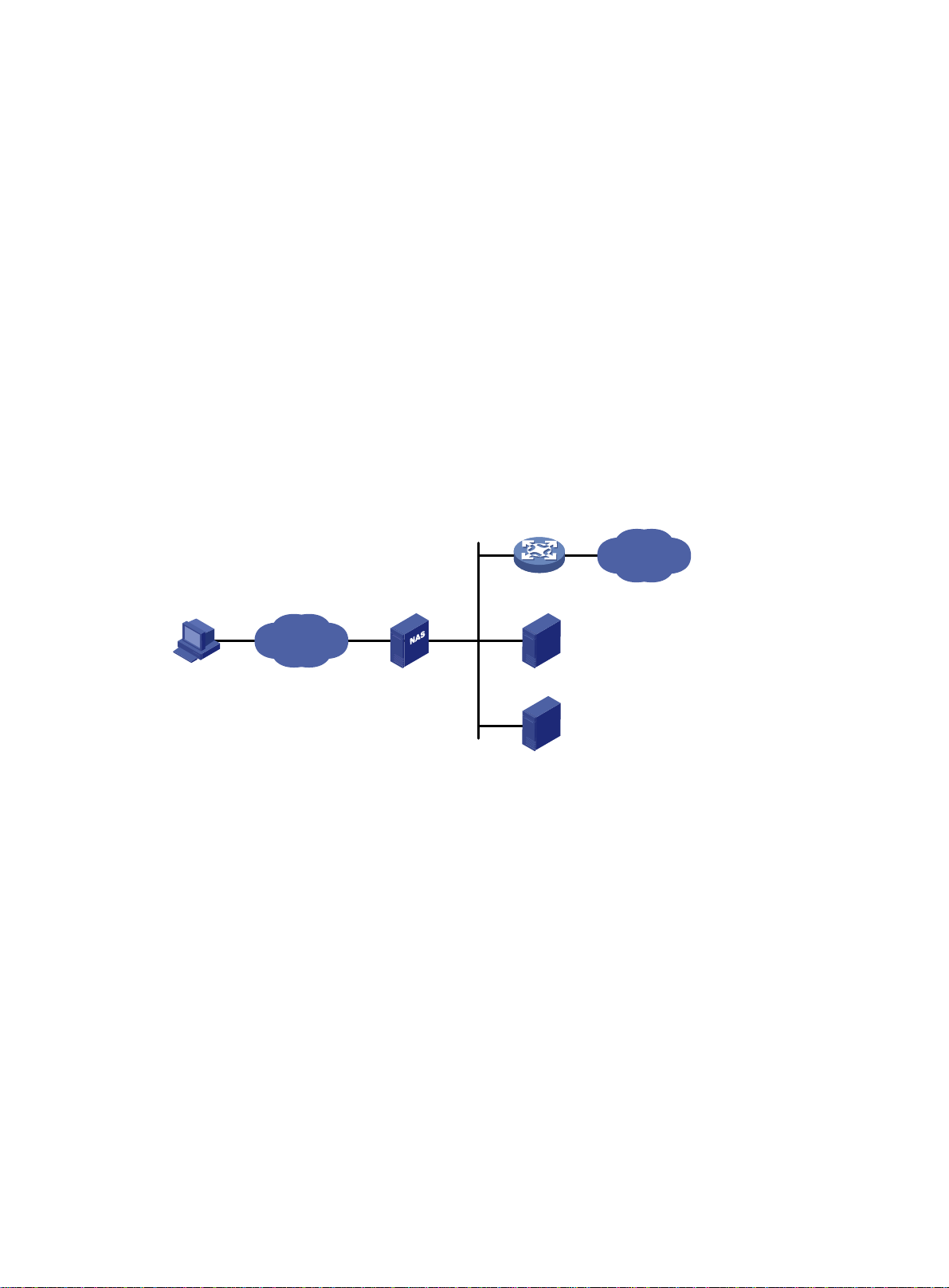
Configuring AAA
Overview
Authentication, Authorization, and Accounting (AAA) provides a uniform framework for implementing
network access management. This feat ure specifies the following security functions:
• Authentication—Identifies users and verifies their validity.
• Authorization—Grants different users different rights, and controls the users' access to
resources and services. For example, you can permit office users to read and print files and
prevent guests from accessing files on the device.
• Accounting—Records network usage details of users, including the service type, start time,
and traffic. This function enables time-based and traffic-based charging and user behavior
auditing.
AAA uses a client/server m odel. The clie nt runs on the access d evice, or the net work access se rver
(NAS), which authenticates user identities and controls user access. The server maintains user
information centrally. See Figure 1.
Figure 1
Remote user
To access networks or resources beyond the NAS, a user sends its identity information to the NAS.
The NAS transparently passes the user information to AAA servers and waits for the authentication,
authorization, and accounting result. Based on the result, the NAS determines whether to permit or
deny the access request.
AAA has various implementations, including RADIUS, HWTACACS, and LDAP. RADIUS is most
often used.
The network in Figure 1 ha
servers to implement different security functions. For example, you can use the HWTACACS server
for authentication and authorization, and use the RADIUS server for accounting.
AAA network diagram
Network
s one RADIUS server and one HWT A CACS server. You can use dif ferent
NAS
RADIUS server
HWTACACS server
Internet
You can choose the security functions provided by AAA as needed. For example, if your company
wants employees to be authenticated before they access specific resources, you would deploy an
authentication server. If network usage information is needed, you would also configure an
accounting server.
The device performs dynamic password authentication.
1
Page 15
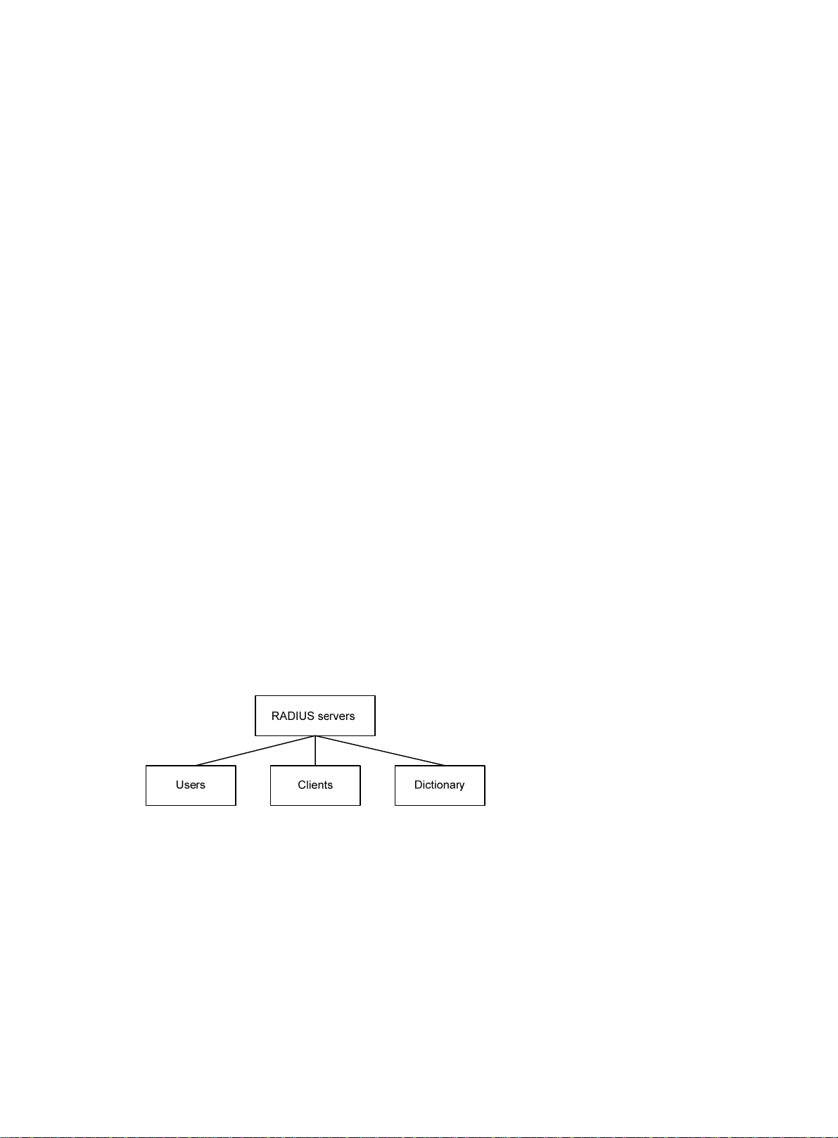
RADIUS
Remote Authentication Dial-In User Service (RADIUS) is a distributed information interaction
protocol that uses a client/server model. The protocol can protect networks against unauthorized
access and is often used in network environments that require both high security and remote user
access.
The RADIUS authorization process is combined with the RADIUS authentication process, and user
authorization information is piggybacked in authentication responses. RADIUS uses UDP port 1812
for authentication and UDP port 1813 for accounting.
RADIUS was originally designed for dial-in user access, and has been extended to support
additional access methods, such as Ethernet and ADSL.
Client/server model
The RADIUS client runs on the NASs located throughout the network. It passes user information to
RADIUS servers and acts on the responses to, for example, reject or accept user access requests.
The RADIUS server runs on the computer or workstation at the network center and maintains
information related to user authentication and network service access.
The RADIUS server operates using the following process:
1. Receives authentication, authorization, and accounting requests from RADIUS clients.
2. Performs user authentication, authorization, or accounting.
3. Returns user access control information (for example, rejecting or accepting the user acce ss
request) to the clients.
The RADIUS server can also act as the client of another RADIUS server to provide authentication
proxy services.
The RADIUS server maintains the following databases:
• Users—Stores user information, such as the usernames, passwords, applied protocols, and IP
addresses.
• Clients—Stores information about RADIUS clients, such as shared keys and IP addresses.
• Dictionary—Stores RADIUS protocol attributes and their values.
Figure 2 RADIUS server databases
Information exchange security mechanism
The RADIUS client and server exchange information between them with the help of shared keys,
which are preconfigured on the client and server. A RADIUS packet has a 16-byte field called
Authenticator. This field includes a signature ge nerated by using the MD5 algorithm, the shared key,
and some other information. The receiver of the packet verifies the si gnature and accepts the packet
only when the signature is correct. This mechanism ensures the security of information exchanged
between the RADIUS client and server.
The shared keys are also used to encrypt user passwords that are included in RADIUS packets.
User authentication methods
The RADIUS server supports multiple user authentication methods, such as PAP, CHAP, and EAP.
2
Page 16
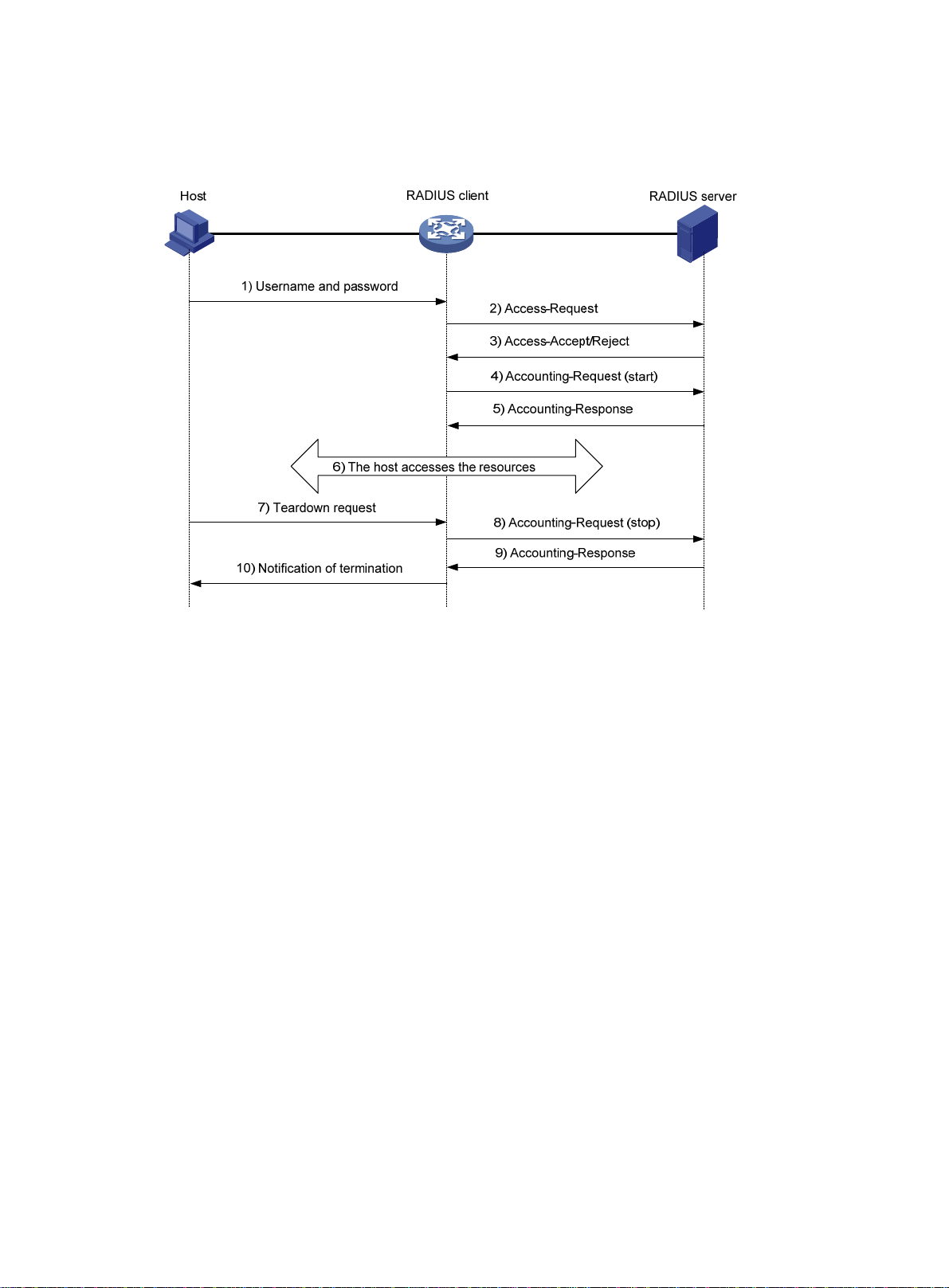
Basic RADIUS packet exchange process
Figure 3 illustrates the interactions between a user host, the RADIUS client, and the RADIUS server.
Figure 3 Basic RADIUS packet exchange process
RADIUS uses the following workflow:
1. The host sends a connection request that includes the user's username and password to the
RADIUS client.
2. The RADIUS client sends an authentication request (Access-Request) to the RADIUS server.
The request includes the user's password, which has been processed by the MD5 algorithm
and shared key.
3. The RADIUS server authenticates the username and password. If the authenticati on succeeds,
the server sends back an Access-Accept packet that contains the user's authorization
information. If the authentication fails, the server returns an Access-Reject packet.
4. The RADIUS client permits or denies the user according to the authentication result. If the result
permits the user, the RADIUS client sends a start-accounting request (Accounting-Request)
packet to the RADIUS server.
5. The RADIUS server returns an acknowledgment (Accounting-Response) packet and starts
accounting.
6. The user accesses the network resources.
7. The host requests the RADIUS client to tear down the connection.
8. The RADIUS client sends a stop-accounting request (Accounting-Reque st) packet to the
RADIUS server.
9. The RADIUS server returns an acknowledgment (Accounting-Response) and stops accounting
for the user.
10. The RADIUS client notifies the user of the termination.
RADIUS packet format
RADIUS uses UDP to transmit packets. The protocol also uses a series of mechanisms to ensure
smooth packet exchange between the RADIUS server and the client. These mechanisms incl ude the
timer mechanism, the retransmission mechanism, and the backup server mechanism.
3
Page 17
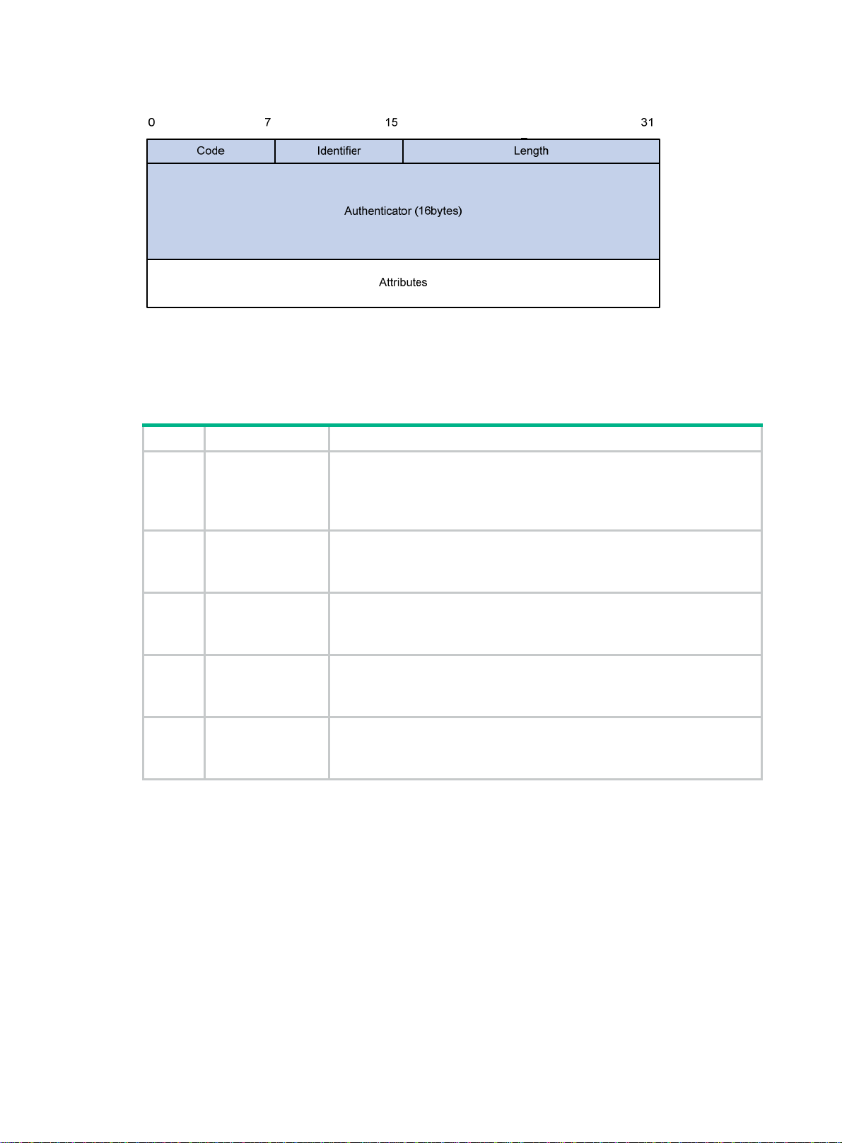
Figure 4 RADIUS packet format
Descriptions of the fields are as follows:
• The Code field (1 byte long) indicates the type of the RADIUS packet. Table 1 g
values and their meanings.
Table 1 Main values of the Code field
Code Packet type Description
From the client to the server. A packet of this type includes user information
1 Access-Request
for the server to authenticate the user. It must contain the User-Name
attribute and can optionally contain the attributes of NAS-IP-Address,
User-Password, and NAS-Port.
ives the main
From the server to the client. If all attribute values included in the
2 Access-Accept
3 Access-Reject
4
5
Accounting-Reque
st
Accounting-Respo
nse
Access-Request are acceptable, the authentication succeeds, and the
server sends an Access-Accept response.
From the server to the client. If any attribute value included in the
Access-Request is unacceptable, the authentication fails, and the server
sends an Access-Reject response.
From the client to the server. A packet of this type includes user information
for the server to start or stop accounting for the user. The Acct-Status-Type
attribute in the packet indicates whether to start or stop accounting.
From the server to the client. The server sends a packet of this type to
notify the client that it has received the Accounting-Request and has
successfully recorded the accounting information.
• The Identifier field (1 byte long) is used to match response packets with request packets and to
detect duplicate request packets. The request and response packets of the same exchange
process for the same purpose (such as authentication or accounting) have the same identifier.
• The Length field (2 bytes long) indicates the length of the entire packet (in bytes), including the
Code, Identifier, Length, Authenticator, and Attributes fields. Bytes beyond this length are
considered padding and are ignored by the receiver. If the length of a received packet is less
than this length, the packet is dropped.
• The Authenticator field (16 bytes long) is used to authenticate responses from the RADIUS
server and to encrypt user passwords. There are two types of authenticators: request
authenticator and response authenticator.
• The Attributes field (variab le in length) includes authentication, authorization, and accounting
information. This field can contain multiple attributes, each with the following subfields:
{ Type—Type of the attribute.
4
Page 18

{ Length—Length of the attribute in bytes, including the Type, Length, and Value subfields.
{ Value—Value of the attribute. Its format and content depend on the Type subfield.
Commonly used RADIUS attributes are defined in RFC 2865, RFC 2866, RFC 2867, and RFC
2868. For more information, see "Commonly used standard RADIUS attributes."
Table 2 Commonly used RADIUS attributes
No. Attribute No. Attribute
1 User-Name 45 Acct-Authentic
2 User-Password 46 Acct-Session-Time
3 CHAP-Password 47 Acct-Input-Packets
4 NAS-IP-Address 48 Acct-Output-Packets
5 NAS-Port 49 Acct-Terminate-Cause
6 Service-Type 50 Acct-Multi-Session-Id
7 Framed-Protocol 51 Acct-Link-Count
8 Framed-IP-Address 52 Acct-Input-Gigawords
9 Framed-IP-Netmask 53 Acct-Output-Gigawords
10 Framed-Routing 54 (unassigned)
11 Filter-ID 55 Event-Timestamp
12 Framed-MTU 56-59 (unassigned)
13 Framed-Compression 60 CHAP-Challenge
14 Login-IP-Host 61 NAS-Port-Type
15 Login-Service 62 Port-Limit
16 Login-TCP-Port 63 Login-LAT-Port
17 (unassigned) 64 Tunnel-Type
18 Reply-Message 65 Tunnel-Medium-Type
19 Callback-Number 66 Tunnel-Client-Endpoint
20 Callback-ID 67 Tunnel-Server-Endpoint
21 (unassigned) 68 Acct-Tunnel-Connection
22 Framed-Route 69 Tunnel-Password
23 Framed-IPX-Network 70 ARAP-Password
24 State 71 ARAP-Features
25 Class 72 ARAP-Zone-Access
26 Vendor-Specific 73 ARAP-Security
27 Session-Timeout 74 ARAP-Security-Data
28 Idle-Timeout 75 Password-Retry
29 Termination-Action 76 Prompt
30 Called-Station-Id 77 Connect-Info
31 Calling-Station-Id 78 Configuration-Token
32 NAS-Identifier 79 EAP-Message
5
Page 19
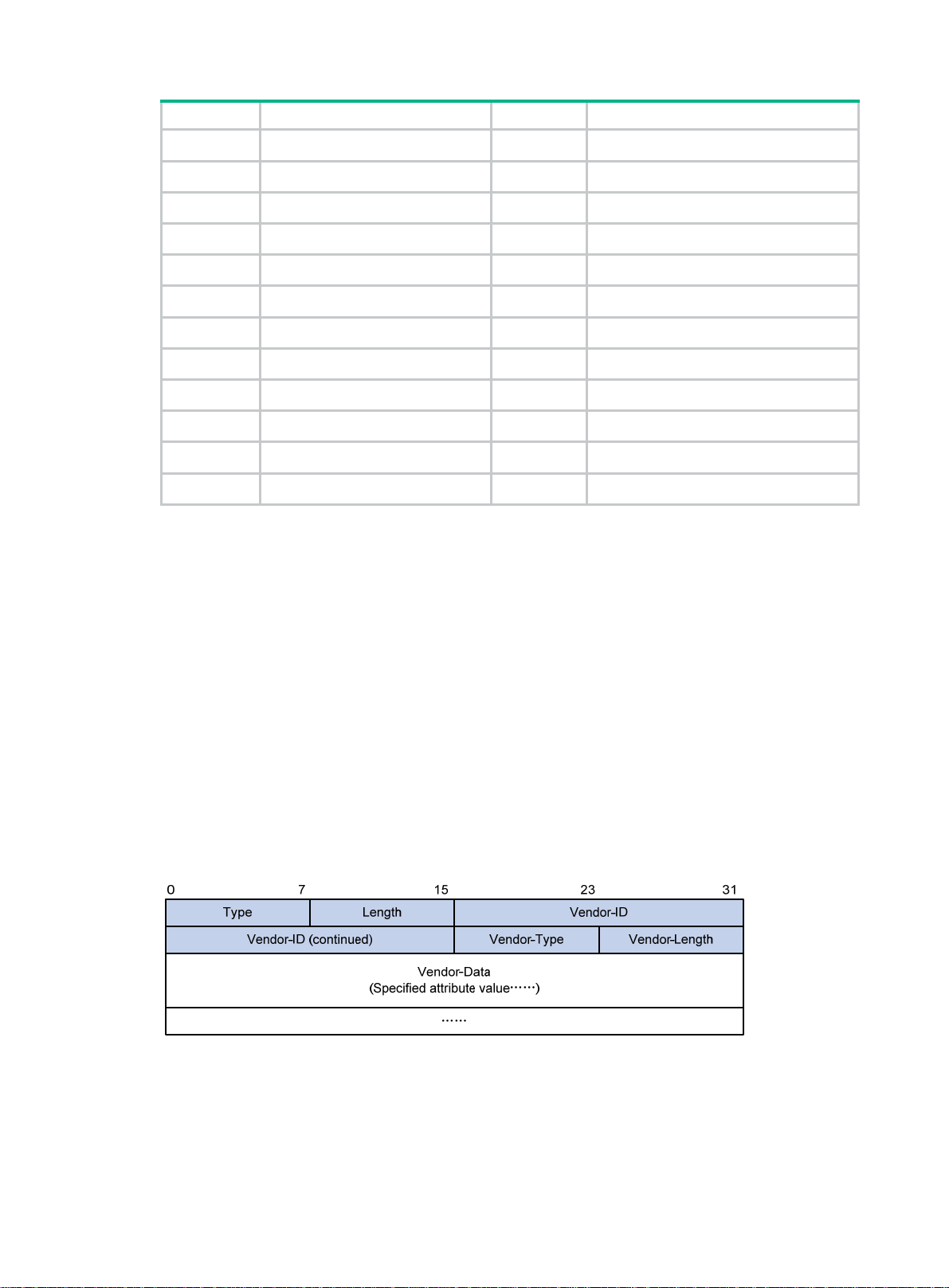
No. Attribute No. Attribute
33 Proxy-State 80 Message-Authenticator
34 Login-LAT-Service 81 Tunnel-Private-Group-id
35 Login-LAT-Node 82 Tunnel-Assignment-id
36 Login-LAT-Group 83 Tunnel-Preference
37 Framed-AppleTalk-Link 84 ARAP-Challenge-Response
38 Framed-AppleTalk-Network 85 Acct-Interim-Interval
39 Framed-AppleTalk-Zone 86 Acct-Tunnel-Packets-Lost
40 Acct-Status-Type 87 NAS-Port-Id
41 Acct-Delay-Time 88 Framed-Pool
42 Acct-Input-Octets 89 (unassigned)
43 Acct-Output-Octets 90 Tunnel-Client-Auth-id
44 Acct-Session-Id 91 Tunnel-Server-Auth-id
Extended RADIUS attributes
The RADIUS protocol features excellent extensibility. The Vendor-Specific attribute (attribute 26)
allows a vendor to define extended attributes. The extended attributes implement functions that the
standard RADIUS protocol does not provide.
A vendor can encapsulate multiple subattributes in the TL V format in attribute 26 to provide exte nded
functions. As shown in Figure 5, a
subattribute encapsulated in attribute 26 consists of the following
parts:
• Vendor-ID—ID of the vendor. The most significant byte is 0. The other three bytes contains a
code compliant to RFC 1700.
• Vendor-Type—Type of the subattribute.
• Vendor-Length—Length of the subattribute.
• Vendor-Data—Contents of the subattribute.
The device supports the RADIUS subattributes with a vendor ID of 25506. For more information, see
"Proprietary RADIUS subattributes (vendor ID 25506)."
Figure 5
Format of attribute 26
HWTACACS
HW Terminal Access Controller Access Control System (HWTACACS) is an enhanced security
protocol based on T ACACS (RFC 1492 ). HWT ACACS is similar to RADIUS, and uses a client/server
model for information exchange between the NAS and the HWTACACS server.
6
Page 20

HWTACACS typically provides AAA services for PPP, VPDN, and terminal users. In a typical
HWT ACA CS scenario, terminal users need to log in to the NAS. Working as the HWTACACS client,
the NAS sends users' usernames and passwords to the HWTACACS server for authentication. After
passing authentication and obtaining authorized rights, a user logs in to the device and performs
operations. The HWTACACS server records the operations that each user performs.
Differences between HWTACACS and RADIUS
HWTACACS and RADIUS have many features in common, such as using a client/server model,
using shared keys for data encryption, and providing flexibility and scalability. Table 3 lists the
ry differences between HWTACACS and RADIUS.
prima
Table 3 Primary differences between HWTACACS and RADIUS
HWTACACS RADIUS
Uses TCP, which provides reliable network
transmission.
Uses UDP, which provides high transport efficiency.
Encrypts the entire packet except for the
HWTACACS header.
Protocol packets are complicated and authorization
is independent of authentication. Authentication and
authorization can be deployed on different
HWTACACS servers.
Supports authorization of configuration commands.
Access to commands depends on both the user's
roles and authorization. A user can use only
commands that are permitted by the user roles and
authorized by the HWTACACS server.
Basic HWTACACS packet exchange process
Figure 6 describes how HWT ACACS perf orms user authentication, a uthorization, and accounting for
a Telnet user .
Encrypts only the user password field in an
authentication packet.
Protocol packets are simple and the authorization
process is combined with the authentication
process.
Does not support authorization of configuration
commands. Access to commands solely depends on
the user's roles. For more information about user
roles, see Fundamentals Configuration Guide.
7
Page 21

Figure 6 Basic HWTACACS packet exchange process for a Telnet user
Host HWTACACS client HWTACACS server
1) The user tries to log in
2) Start-authentication packet
3) Authentication response requesting the username
4) Request for username
5) The user enters the username
6) Continue-authentication packet with the username
7) Authentication response requesting the password
8) Request for password
9) The user enters the password
10) Continue-authentication packet with the password
11) Response indicating successful authentication
12) User authorization request packet
13) Response indicating successful authorization
14) The user logs in successfully
15) Start-accounting request
16) Response indicating the start of accounting
17) The user logs off
18) Stop-accounting request
19) Stop-accounting response
HWTACACS operates using the following workflow:
1. A Telnet user sends an access request to the HWTACACS client.
2. The HWTACACS client sends a start-authentication packet to the HWTACACS server when it
receives the request.
3. The HWTACACS server sends back an authentication response to request the username.
4. Upon receiving the response, the HWTACACS client asks the user for the username.
5. The user enters the username.
6. After receiving the username from the user, the HWTACACS client sends the server a
continue-authentication packet that includes the username.
7. The HWTACACS server sends back an authentication response to request the login password.
8. Upon receipt of the response, the HWTACACS client prompts the user for the login password.
9. The user enters the password.
8
Page 22

10. After receiving the login password, the HWTACACS client sends the HWTACACS serv er a
11. If the authentication succeeds, the HWTACACS server sends back an authenti cation response
12. The HWTACACS client sends a user authorization request packet to the HWTACACS server.
13. If the authorization succeeds, the HWTACACS server sends back an authorization response,
14. Knowing that the user is now authorized, the HWTACACS client pushes its CLI to the user and
15. The HWTACACS client sends a start-accounting request to the HWTACACS server.
16. The HWTACACS server sends back an accounting response, indi cating that it has received the
17. The user logs off.
18. The HWTACACS client sends a stop-accounting request to the HWTACACS server.
19. The HWTACACS server sends back a stop-accounting response, indicating that the
LDAP
The Lightweight Directory Access Proto col (LDAP) provides stan dard multiplatform directory service.
LDAP was developed on the basis of the X.500 protocol. It improves the following functions of X.500:
• Read/write interactive access.
• Browse.
• Search.
continue-authentication packet that includes the login password.
to indicate that the user has passed authentication.
indicating that the user is now authorized.
permits the user to log in.
start-accounting request.
stop-accounting request has been received.
LDAP is suitable for storing data that does not often change. The protocol is used to store user
information. For example, LDAP server software Active Directory Server is used in Microsoft
Windows operating systems. The software stores the user information and user group information
for user login authentication and authorization.
LDAP directory service
LDAP uses directories to maintain the organization informatio n, personnel information, and resource
information. The directories are organized in a tree structure and include entries. An entry is a set of
attributes with distinguished names (DNs). The attributes are used to store information such as
usernames, passwords, emails, computer names, and phone numbers.
LDAP uses a client/server model, and all directory information is stored in the LDAP server.
Commonly used LDAP server products include Microsoft Active Directory Server, IBM Tivoli
Directory Server, and Sun ONE Directory Server.
LDAP authentication and authorization
AAA can use LDAP to provide authentication and authorization services for users. LDAP defines a
set of operations to implement its functions. The main operations for authentication and authori zation
are the bind operation and search operation.
• The bind operation allows an LDAP client to perform the following operations:
{ Establish a connection with the LDAP server.
{ Obtain the access rights to the LDAP server.
{ Check the validity of user information.
• The search operation constructs search conditions and obtains the directory re source
information of the LDAP server.
In LDAP authentication, the client completes the following operations:
9
Page 23
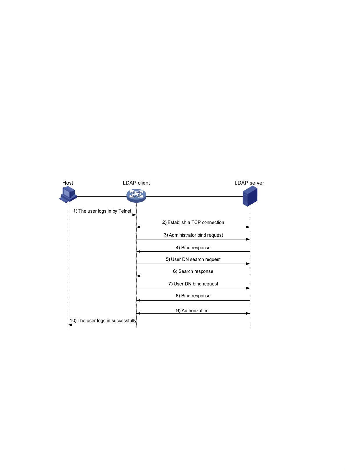
1. Uses the LDAP server administrator DN to bind with the LDAP server. After the binding is
created, the client establishes a connection to the server and obtains the right to search.
2. Constructs search conditions by using the username in the authentication information of a u ser.
The specified root directory of the server is searched and a user DN list is generated.
3. Binds with the LDAP server by using each user DN and password. If a binding is created, the
user is considered legal.
In LDAP authorization, the client performs the same operations as in LDAP authentication. Wh en the
client constructs search conditions, it obtains both authorization information and the user DN list.
• If the authorization information meets the authorization requirements, the authorization process
ends.
• If the authorization information does not meet the authorization requirements, the client sends
an administrator bind request to the LDAP server. This operation obtains the right to search for
authorization information about users on the user DN list.
Basic LDAP packet exchange process
The following example illustrates the basic packet exchange process during LDAP authentication
and authorization for a Telnet user.
Figure 7 Basic packet exchange process for LDAP authentication of a Telnet user
The basic packet exchange process is as follows:
1. A Telnet user initiates a connection request and sends the username and password to the
LDAP client.
2. After receiving the request, the LDAP client establishes a TCP connection with the LDAP
server.
3. To obtain the right to search, the LDAP client uses the administrator DN and password to send
an administrator bind request to the LDAP server.
4. The LDAP server processes the request. If the bind operation is successful, the LDAP server
sends an acknowledgment to the LDAP client.
5. The LDAP client sends a user DN search request with the username of the Telnet user to the
LDAP server.
10
Page 24
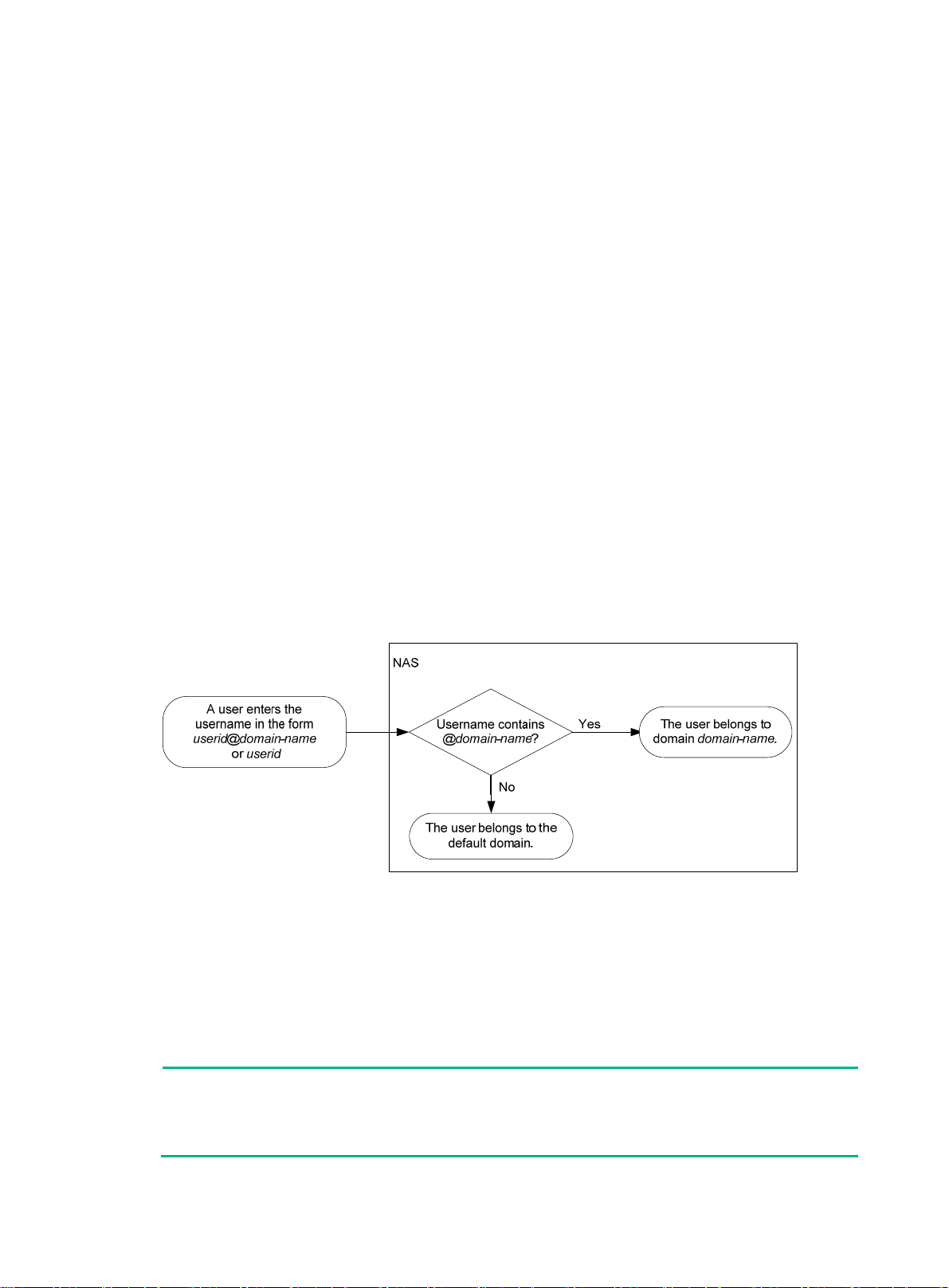
6. After receiving the request, the LDAP server searches for the use r DN by the base DN, sea rch
scope, and filtering conditions. If a match is found, the LDAP server sends a response to notify
the LDAP client of the successful search. There might be one or more user DNs found.
7. The LDAP client uses the obtained user DN and the entered user password as parameters to
send a user DN bind request to the LDAP server. The server will check whether the user
password is correct.
8. The LDAP server processes the request, and sends a response to notify the LDAP client of the
bind operation result. If the bind operation fails, the LDAP client uses another obtained user DN
as the parameter to send a user DN bind request to the LDAP server. This process continues
until a DN is bound successfully or all DNs fail to be bound. If all user DNs fail to be bound, the
LDAP client notifies the user of the login failure and denies the user's access request.
9. The LDAP client and server perform authorization exchanges. If another scheme (for example,
an HWTACACS scheme) is expected for authorization, the LDAP client exchanges
authorization packets with the HWTACACS authorization server instead.
10. After successful authorization, the LDAP client notifies the user of the successful login.
AAA implementation on the device
This section describes AAA user mana gement and methods.
User management based on ISP domains and user access types
AAA manages users based on the users' ISP domains and access types.
On a NAS, each user belongs to one ISP domain. The NAS determines the ISP domain to which a
user belongs based on the username entered by the user at login.
Figure 8 Determining the ISP domain for a user by username
AAA manages use rs in the same ISP domain based on the users' access types. The device supports
the following user access types:
• LAN—LAN users must pass 802.1X or MAC authentication to come online.
• Login—Login users include SSH, Telnet, FTP, and terminal users who log in to the device.
Terminal users can access through console ports.
• Portal—Portal users must pass portal authentication to access the network.
• Web—Web users log in to the Web interface of the device through HTTP or HTTPS.
NOTE:
The device also provides authentication modules (such as 802.1X) for implementation of user
authentication management policies. If you configure these authentication modules, the ISP
domains for users of the access types depend on the configuration of the authentication modules.
11
Page 25

AAA methods
AAA supports configuring different authentication, authorization, and accounting methods for
different types of users in an ISP domain. The N AS determines the ISP domain and access type of a
user. The NAS also uses the methods configured for the access type in the domain to control the
user's access.
AAA also supports configuring a set of default methods for an ISP domain. These default methods
are applied to users for whom no AAA method s are configured.
The device supports the following authentication methods:
• No authentication—This method trusts all users and does not perform authentication. For
security purposes, do not use this method.
• Local authentication—The NAS authenticates users by itself, based on the locally configured
user information including the usernames, passwords, and attributes. Local authentication
allows high speed and low cost, but the amount of information that can be stored is limited by
the size of the storage space.
• Remote authentication—The NAS works with a RADIUS, HWTACACS, or LDAP server to
authenticate users. The server manages user information in a centralized manner. Remote
authentication provides high capacity, reliable, and centralized authentication services for
multiple NASs. You can configure backup methods to be used when the remote server is not
available.
The device supports the following authorization methods:
• No authorization—The NAS performs no authorization exchange. The following default
authorization information applies after users pass authentication:
{ Non-login users can access the network.
{ Login users are assigned the default user role. For more information about the default user
{ FTP, SFTP , and SCP login users also ha ve the root directory of the NAS set as the wo rking
• Local authorization—The NAS performs authorization according to the user attributes locally
configured for users.
• Remote authorization—The NAS works with a RADIUS, HWTACACS, or LDAP server to
authorize users. RADIUS authorization is bound with RADIUS authentication. RADIUS
authorization can work only after RADIUS authentication is successful, and the authorization
information is included in the Access-Accept packet. HWTACACS authorization is separate
from HWTACACS authentication, and the authorization information is included in the
authorization response after successful authentication. You can configure backup methods to
be used when the remote server is not available.
role feature, see Fundamentals Configuration Guide.
directory. However, the users do not have permission to access the root directory.
The device supports the following accounting methods:
• No accounting—The NAS does not perform accounting for the users.
• Local accounting—Local accounting is implemented on the NAS. It counts and controls the
number of concurrent users who use the same local user account, but does not provide
statistics for charging.
• Remote accounting—The NAS works with a RADIUS server or HWTACACS server for
accounting. You can configure ba ckup methods to be used when the remote server is not
available.
In addition, the device provides the following login services to enhance device security:
• Command authorization—Enables the NAS to let the authorization server determine whether
a command entered by a login user is permitted. Login users can execute only commands
permitted by the authorization server. Fo r more info rm ation about command auth orization, see
Fundamentals Configuration Guide.
12
Page 26
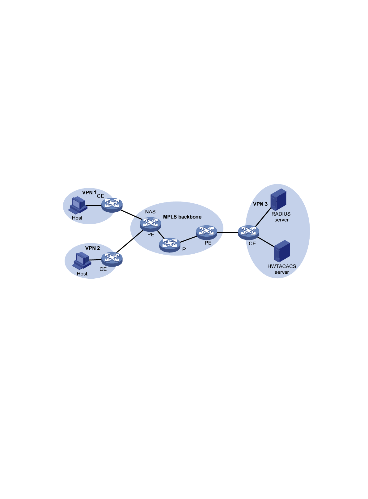
• Command accounting—When command authorization is disabled, command accounting
enables the accounting server to record all valid commands executed on the device. When
command authorization is enabled, command accounting enables the accounting server to
record all authorized commands. For more information about command accounting, see
Fundamentals Configuration Guide.
• User role authentication—Authenticates each user who wants to obtain another user role
without logging out or getting disconnected. For more information about user role authentication,
see Fundamentals Configuration Guide.
AAA for MPLS L3VPNs
You can deploy AAA across VPNs in an MPLS L3VPN scenario where clients in different VPNs are
centrally authenticated. The deployment enables forwarding of RADIUS and HWTACACS packets
across MPLS VPNs. For example, as shown in Figure 9, you can deploy
PE at the left side of the MPLS backbone acts as a NAS. The NAS transparently delivers the AAA
packets of private users in VPN 1 and VPN 2 to the AAA servers in VPN 3 for centralized
authentication. Authentication packets of private users in different VPNs do not affect each other.
Figure 9 Network diagram
AAA across the VPNs. The
This feature can also help an MCE to implement portal authentication for VPNs. For more
information about MCE, see MPLS Configuration Guide. For more information about portal
authentication, see "Configuring portal authentication."
Protocols and standards
• RFC 2865, Remote Authentication Dial In User Service (RADIUS)
• RFC 2866, RADIUS Accounting
• RFC 2867, RADIUS Accounting Modifications for Tunnel Protocol Support
• RFC 2868, RADIUS Attributes for Tunnel Protocol Support
• RFC 2869, RADIUS Extensions
• RFC 5176, Dynamic Authorization Extensions to Remote Authentication Dial In User Service
(RADIUS)
• RFC 1492, An Access Control Protocol, Sometimes Called T ACACS
• RFC 1777, Lightweight Directory Access Proto col
• RFC 2251, Lightweight Directory Access Protocol (v3 )
13
Page 27

RADIUS attributes
Commonly used standard RADIUS attributes
No. Attribute Description
1 User-Name Name of the user to be authenticated.
2 User-Password
3 CHAP-Password
4 NAS-IP-Address
5 NAS-Port Physical port of the NAS that the user accesses.
6 Service-Type
7 Framed-Protocol Encapsulation protocol for framed access.
8 Fr amed-IP-Address IP address assigned to the user.
11 Filter-ID Name of the filter list.
12 Framed-MTU
14 Login-IP-Host IP address of the NAS interface that the user accesses.
15 Login-Service Type of the service that the user uses for login.
18 Reply-Message
User password for PAP authentication, only present in Access-Request
packets when PAP authentication is used.
Digest of the user password for CHAP authentication, only present in
Access-Request packets when CHAP authentication is used.
IP address for the server to use to identify the client. Typically, a client is
identified by the IP address of its access interface. This attribute is only
present in Access-Request packets.
Type of service that the user has requested or type of service to be
provided.
MTU for the data link between the user and NAS. For example, with
802.1X EAP authentication, NAS uses this attribute to notify the server of
the MTU for EAP packets to avoid oversized EAP packets.
Text to be displayed to the user, which can be used by the server to
communicate information, for example, the reason of the authentication
failure.
Vendor-specific proprietary attribute. A packet can contain one or more
26 Vendor-Specific
27 Session-Timeout Maximum service duration for the user before termination of the session.
28 Idle-Timeout
31 Calling-Station-Id
32 NAS-Identifier Identification that the NAS uses to identify itself to the RADIUS server.
40 Acct-Status-Type
proprietary attributes, each of which can contain one or more
subattributes.
Maximum idle time permitted for the user before termination of the
session.
User identification that the NAS sends to the server. For the LAN access
service provided by an HPE device, this attribute includes the MAC
address of the user in the format HHHH-HHHH-HHHH.
Type of the Accounting-Request packet. Possible values include:
• 1—Start.
• 2—Stop.
• 3—Interim-Update.
• 4—Reset-Charge.
• 7—Accounting-On. (Defined in the 3rd Generation Partnership
Project.)
• 8—Accounting-Off. (Defined in the 3rd Generation Partnership
Project.)
• 9 to 14—Reserved for tunnel accounting.
• 15—Reserved for failed.
14
Page 28

No. Attribute Description
Authentication method used by the user. Possible values include:
45 Acct-Authentic
• 1—RADIUS.
• 2—Local.
• 3—Remote.
60 CHAP-Challenge
61 NAS-Port-Type
79 EAP-Message
80
87 NAS-Port-Id String for describing the port of the NAS that is authenticating the user.
Message-Authenticato
r
CHAP challenge generated by the NAS for MD5 calculation during CHAP
authentication.
Type of the physical port of the NAS that is authenticating the user.
Possible values include:
• 15—Ethernet.
• 16—Any type of ADSL.
• 17—Cable. (With cable for cable TV.)
• 19—WLAN-IEEE 802.11.
• 201—VLAN.
• 202—ATM.
If the port is an ATM or Ethernet one and VLANs are implemented on it,
the value of this attribute is 201.
Used to encapsulate EAP packets to allow RADIUS to support EAP
authentication.
Used for authentication and verification of authentication packets to
prevent spoofing Access-Requests. This attribute is present when EAP
authentication is used.
Proprietary RADIUS subattributes (vendor ID 25506)
No. Subattribute Description
1 Input-Peak-Rate Peak rate in the direction from the user to the NAS, in bps.
2 Input-Average-Rate Average rate in the direction from the user to the NAS, in bps.
3 Input-Basic-Rate Basic rate in the direction from the user to the NAS, in bps.
4 Output-Peak-Rate Peak rate in the direction from the NAS to the user, in bps.
5 Output-Average-Rate Average rate in the direction from the NAS to the user, in bps.
6 Output-Basic-Rate Basic rate in the direction from the NAS to the user, in bps.
15 Remanent_Volume
20 Command
24 Control_Identifier
Total amount of data available for the connection, in different units for
different server types.
Operation for the session, used for session control. Possible values
include:
• 1—Trigger-Request.
• 2—Terminate-Request.
• 3—SetPolicy.
• 4—Result.
• 5—PortalClear.
Identification for retransmitted packets. For retransmitted packets from
the same session, this attribute must be the same value. For
retransmitted packets from different sessions, this attribute does not
have to be the same value. The client response of a retransmitted
packet must also include this attribute and the value of this attribute
must be the same.
For Accounting-Request packets of the start, stop, and interim update
15
Page 29

No. Subattribute Description
types, the Control_Identifier attribute does not take effect.
25 Result_Code
26 Connect_ID Index of the user connection.
28 Ftp_Directory
29 Exec_Privilege EXEC user priority.
59 NAS_Startup_Timestamp
60 Ip_Host_Addr
61 User_Notify
62 User_HeartBeat
140 User_Group
Result of the Trigger-Request or SetPolicy operation, zero for success
and any other value for failure.
FTP, SFTP, or SCP user working directory.
When the RADIUS client acts as the FTP, SFTP, or SCP server, this
attribute is used to set the working directory for an FTP, SFTP, or SCP
user on the RADIUS client.
Startup time of the NAS in seconds, which is represented by the time
elapsed after 00:00:00 on Jan. 1, 1970 (UTC).
User IP address and MAC address included in authentication and
accounting requests, in the format A.B.C.D hh:hh:hh:hh:hh:hh. A
space is required between the IP address and the MAC address.
Information that must be sent from the server to the client
transparently.
Hash value assigned after an 802.1X user passes authentication,
which is a 32-byte string. This attribute is stored in the user list on the
NAS and verifies the handshake packets from the 802.1X user. This
attribute only exists in Access-Accept and Accounting-Request
packets.
User groups assigned after the SSL VPN user passes authentication.
A user can belong to multiple user groups that are separated by
semicolons. This attribute is used to work with the SSL VPN device.
141 Security_Level
201 Input-Interval-Octets Number of bytes input within a realtime accounting interval.
202 Output-Interval-Octets Number of bytes output within a realtim e accounting interval.
203 Input-Interval-Packets
204 Output-Interval-Packets
205 Input-Interval-Gigawords
206
207 Backup-NAS-IP Backup source IP address for sending RADIUS packets.
255 Product_ID Product name.
Output-Interval-Gigawords Amount of bytes output within an accounting interval, in units of 4G
FIPS compliance
The device supports the FIPS mode that complies with NIST FIPS 140-2 requirements. Support for
features, commands, and parameters might differ in FIPS mode (see "Configuring FIPS") and
non-FIPS mode.
Security level assigned after the SSL VPN user passes security
authentication.
Number of packets input within an accounting interval in the unit set on
the NAS.
Number of packets output within an accounting interval in the unit set
on the NAS.
Amount of bytes input within an accounting interval, in units of 4G
bytes.
bytes.
16
Page 30
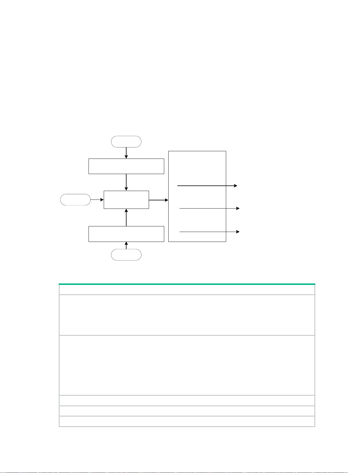
AAA configuration considerations and task list
To configure AAA, complete the following tasks on the NAS:
1. Configure the required AAA schemes.
{ Local authentication—Configure local users and the related attributes, including the
usernames and passwords, for the users to be authenticated.
{ Remote authentication—Configure the required RADIUS, HWTACACS, and LDAP
schemes.
2. Configure AAA methods for the users' ISP domains. To use remote AAA methods, you must
specify the configured RADIUS, HWTACACS, or LDAP schemes in ISP domain view.
Figure 10 AAA configuration procedure
Local AAA
Configure AAA methods for
Configure local users and related
attributes
different types of users or/and
the default methods for all
types of users
No AAA
To configure AAA, perform the following tasks:
Create an ISP domain
and enter ISP domain
view
Configure the RADIUS, HWTACACS,
or LDAP schemes to be used
Remote AAA
Authentication method
+
Authorization method
+
Accounting method
none/ local (the default)/scheme
none/ local (the default)/scheme
none/ local (the default)/scheme
Tasks at a glance
(Required.) Perform at least one of the following tasks to configure local users or AAA schemes:
• Configuring local users
• Configuring RADIUS schemes
• Configuring HWTACACS schemes
• Configuring LDAP schemes
(Required.) Configure AAA methods for ISP domains:
1. (Required.) Creating an ISP domain
2. (Optiona
3. (Req
and accounting methods for the ISP domain:
{ Configuring authentication methods for an ISP domain
{ Configuring authorization methods for an ISP domain
{ Configuring accounting methods for an ISP domain
l.) Configuring ISP domain attributes
uired.) Perform at least one of the following tasks to configure AAA authentication, authorization,
(Optional.) Enabling the session-control feature
(Optional.) Configuring the RADIUS DAE server feature
(Optional.) Setting the maximum number of concurrent login users
17
Page 31

Tasks at a glance
(Optional.) Configuring a NAS-ID profile
Configuring AAA schemes
This section includes information on configuring local users, RADIUS schemes, HWTACACS
schemes, and LDAP schemes.
Configuring local users
To implement local authentication, authorization, and accounting, create local users and configure
user attributes on the device. The local users and attributes are stored in the local user database on
the device. A local user is uniquely identified by the combination of a username and a user type.
Local users are classified into the following types:
• Device management user—User who logs in to the device for device manage ment.
• Network access user—User who accesses network resources through the device.
The following shows the configurable local user attributes:
• Service type—Services that the user can use. Local authentication checks the service types of
a local user. If none of the service types is available, the user cannot pass authentication.
Service types include FTP, HTTP, HTTPS, LAN access, portal, SSH, Telnet, and terminal.
• User state—There are two user states: active and blocked. A user in active state can request
network services. A user in blocked state cannot request authentication, authorization, and
accounting services, but it can request to stop the accounting service in use.
• Upper limit of concurrent logins using the same user name—Maximum number of users
who can concurrently access the device by using the same user name. When the number
reaches the upper limit, no more local users can access the device by using the user name.
• User group—Each local user belongs to a local user group and has all attributes of the group.
The attributes include the password control attributes and authorization attributes. For more
information about local user group, see "Configuring user group attributes."
• Binding attributes—Binding attributes control the scope of users, and are checked during
local authentication of a user. If the attributes of a user do not match the binding attributes
configured for the local user account, the user cannot pass authentication. Binding attributes
include the IP address, access port, MAC address, and native VLAN. For support and usag e
information about binding attributes, see "Configuring local user attributes."
• Authorization attributes—Authorization attributes are assigned to a user after the user
passes local authentication. For support information about authorization attributes, see
"Configuring local user attributes."
ure the authorization attributes based on the service type of local users.
Config
You can configure an authorization attribute in user group view or local user view. The setting of
an authorization attribute in local user view takes precedence over the attribute setting in user
group view.
{ The attribute configured in user group view takes ef fect on all local use rs in the u ser group.
{ The attribute configured in local user view takes effect only on the local user.
• Password control attributes—Password control attributes help control password security for
device management users. Password control attributes include password aging time, minimum
password length, password composition checking, password complexity checking, and login
attempt limit.
You can configure a password control attribute in system view, user group view, or local user
view. A password control attribute with a smaller effective range has a higher priority. For more
18
Page 32

information about password management and global password configuration, see "Configuring
password control."
Local user configuration task list
Tasks at a glance
(Required.) Configuring local user attributes
(Optional.) Configuring user group attributes
(Optional.) Displaying and maintaining local users and local user groups
Configuring local user attributes
When you configure local user attributes, follow these guidelines:
• When you use the password-control enable command to globally enable the password
control feature, local user passwords are not displayed.
• You can configure authorization attributes and password control attributes in local user view or
user group view. The setting in local user view takes precedence over the setting in user group
view.
• Configure the location binding attribute based on the service types of users.
{ For 802.1X users, specify the 802.1X-enabled Layer 2 Ethernet interfaces through which
the users access the device.
{ For MAC authentication users, specify the MAC authentication-enabled Layer 2 Ethernet
interfaces through which the users access the device.
{ For portal users, specify the portal-enabled interfaces through which the users access the
device. Specify the Layer 2 Ethernet interfaces if portal is enabled on VLAN interfaces and
the portal roaming enable command is not configured.
To configure local user attributes:
Step Command Remarks
1. Enter system view.
2. Add a local user and enter
local user view.
3. (Optional.) Configure a
password for the local
user.
4. Assign services to the
local user.
system-view
local-user
manage | network
{
user-name [
class
} ]
• For a network access user:
password { cipher | simple }
password
• For a device management
user:
{ In non-FIPS mode:
password [ { hash |
simple } password ]
{ In FIPS mode:
password
• For a network access user:
service-type { lan-access |
portal }
• For a device management
user:
N/A
By default, no local user exists.
Network access user passwords are
encrypted with the encryption
algorithm and saved in ciphertext.
Device management user
passwords are encrypted with the
hash algorithm and saved in
ciphertext.
In non-FIPS mode, a
non-password-protected user
passes authentication if the user
provides the correct username and
passes attribute checks. To
enhance security, configure a
password for each local user.
In FIPS mode, only
password-protected users can pass
authentication.
By default, no service is authorized
to a local user.
19
Page 33

Step Command Remarks
{ In non-FIPS mode:
service-type { ftp | { http |
https | ssh | telnet |
terminal } * }
{ In FIPS mode:
service-type { https | ssh
| terminal } *
5. (Optional.) Place the local
user to the active or
blocked state.
6. (Optional.) Set the upper
limit of concurrent logins
using the local user
name.
state { active | block
access-limit
max-user-number
}
By default, a created local user is in
active state and can request
network services.
By default, the number of concurrent
logins is not limited for the local
user.
This command takes effect only
when local accounting is configured
for the local user. It does not apply to
FTP, SFTP, or SCP users, who do
not support accounting.
7. (Optional.) Configure
binding attributes for the
local user.
8. (Optional.) Configure
authorization attributes
for the local user.
9. (Optional.) Configure
password control
attributes for the local
user.
bind-attribute
location interface
interface-number |
mac-address |
authorization-attribute
acl-number |
ip-pool
ipv6-pool-name |
profile-name |
vlan
|
vlan-id |
directory-name } *
{ ip ip-address |
vlan
idle-cut
pool-name |
user-profile
user-role
work-directory
interface-type
mac
{
acl
vlan-id } *
minute |
ipv6-pool
role-name
• Set the password aging time:
password-control aging
aging-time
• Set the minimum password
length:
password-control length
length
• Configure the password
composition policy:
password-control
composition type-number
type-number [ type-length
type-length ]
• Configure the password
complexity checking policy:
password-control
complexity
{ same-character |
user-name } check
• Configure the maximum login
attempts and the action to
take if there is a login failure:
password-control
login-attempt login-times
By default, no binding attribute is
configured for a local user.
The following default settings apply:
• FTP, SFTP, and SCP users
have the root directory of the
NAS set as the working
directory. However, the users
do not have permission to
access the root directory.
• The network-operator user role
is assigned to local users that
are created by a
network-admin or level-15
user.
Optional.
By default, the local user uses
password control attributes of the
user group to which the local user
belongs.
Only device management users
support the password control
feature.
20
Page 34

Step Command Remarks
10. (Optional.) Assign the
local user to a user group.
Configuring user group attributes
User groups simplify local user configuration and management. A user group contains a group of
local users and has a set of local user attributes. You can configure local user attributes for a user
group to implement centralized user attributes management for the local users in the group. Local
user attributes that are manageable include authorization attributes.
By default, every new local user belongs to the default user group system and has all attributes of
the group. To assign a local user to a different user group, use the group command in local user
view.
To configure user group attributes:
Step Command Remarks
1. Enter system view.
[ exceed { lock | lock-time
time | unlock } ]
group
group-name
system-view
By default, a local user belongs to
the default user group
N/A
system
.
2. Create a user group and
enter user group view.
3. Configure authorization
attributes for the user
group.
4. (Optional.) Configure
password control attributes
for the user group.
user-group
authorization-attribute
acl-number |
ip-pool
ipv6-pool-name |
profile-name |
work-directory
• Set the password aging time:
password-control aging
aging-time
• Set the minimum password
length:
password-control length
length
• Configure the password
composition policy:
password-control
composition type-number
type-number [ type-length
type-length ]
• Configure the password
complexity checking policy:
password-control complexity
{ same-character |
user-name } check
• Configure the maximum login
attempts and the action to take
for login failures:
password-control
login-attempt login-times
[ exceed { lock | lock-time time
| unlock } ]
group-name
idle-cut
pool-name |
vlan
directory-name } *
acl
{
minute |
ipv6-pool
user-profile
vlan-id |
By default, there is a
system-defined user group
named
default user group.
By default, no authorization
attributes are configured for a
user group.
Optional.
By default, the user group uses
the global password control
settings. For more information,
see "Configuring password
control."
system
, which is the
21
Page 35

Displaying and maintaining local users and local user groups
Execute display commands in any view .
Task Command
Display the local user
configuration and online user
statistics.
Display the user group
configuration.
display local-user
enable
telnet
manage | network
{
display user-group
service-type
} |
terminal
|
Configuring RADIUS schemes
A RADIUS scheme specifies the RADIUS serve rs that the device can wo rk with and defin es a set of
parameters. The device uses the parameters to exchange information with the RADIUS servers,
including the server IP addresses, UDP port numbers, shared key s , and server types.
Configuration task list
Tasks at a glance
(Optional.) Configuring a test profile for RADIUS server status detection
(Required.) Creating a RADIUS scheme
(Required.) Specifying the RADIUS authentication servers
(Optional.) Specifying the RADIUS accounting servers and the relevant parameters
(Optional.) Specifying the shared keys for secure RADIUS communication
class { manage | network
[
ftp
http
{
state
} |
{
vlan
} |
[ group-name ]
|
active
vlan-id ]
|
block
|
https
lan-access
|
user-name
} |
idle-cut
} |
disable
{
portal
|
user-name
|
ssh
|
|
class
(Optional.) Specifying an MPLS L3VPN instance for the scheme
(Optional.) Setting the username format and traffic statistics units
(Optional.) Setting the maximum number of RADIUS request transmission attempts
(Optional.) Setting the status of RADIUS servers
(Optional.) Enabling the RADIUS server load sharing feature
(Optional.) Specifying the source IP address for outgoing RADIUS packets
(Optional.) Setting RADIUS timers
(Optional.) Configuring the accounting-on feature
(Optional.) Configuring the IP addresses of the security policy servers
(Optional.) Configuring the Login-Service attribute check method for SSH, FTP, and terminal us ers
(Optional.) Enabling SNMP notifications for RADIUS
(Optional.) Displaying and maintaining RADIUS
Configuring a test profile for RADIUS server status detection
Use a test profile to detect whether a RADIUS authentication server is reachable at a detection
interval. To detect the RADIUS server status, you must configure the RADIUS server to use this test
profile in a RADIUS scheme.
With the test profile specified, the device sends a detection packet to the RA DIUS server within each
detection interval. The detection packet is a simulated authentication request that includes the
specified user name in the test profile.
22
Page 36

• If the device receives a response from the server within the interval, it sets the server to the
active state.
• If the device does not receive any response from the server within the interval, it sets the server
to the blocked state.
The device refreshes the RADIUS server status at each detection interval according to the detection
result.
The device stops detecting the status of the RADIUS server when one of the foll owing ope rati ons i s
performed:
• The RADIUS server is removed from the RADIUS scheme.
• The test profile configuration is removed for the RADIUS server in RADIUS scheme view.
• The test profile is deleted.
• The RADIUS server is manually set to the blocked state.
• The RADIUS scheme is deleted.
To configure a test profile for RADIUS server status detection:
Step Command Remarks
1. Enter system view.
2. Configure a test profile for
detecting the status of
RADIUS authentication
servers.
system-view
radius-server test-profile
profile-name
interval
[
username
interval ]
name
N/A
By default, no test profiles exist.
You can configure multiple test
profiles in the system.
Creating a RADIUS scheme
Create a RADIUS scheme before performing any other RADIUS configurations. You can configure a
maximum of 16 RADIUS schemes. A RADIUS scheme can be used by multiple ISP domains.
To create a RADIUS scheme:
Step Command Remarks
1. Enter system view.
2. Create a RADIUS scheme
and enter RADIUS scheme
view.
system-view
radius scheme
radius-scheme-name
Specifying the RADIUS authentication servers
N/A
The default setting depends on
the type of the startup
configuration:
• If the device starts up with
initial settings, no RADIUS
scheme is defined.
• If the device starts up with
the factory defaults, a
RADIUS scheme named
system is defined.
For more information about the
startup configuration, see
Fundamentals Configuration
Guide.
A RADIUS authentication server completes authentication and authorization together, because
authorization information is piggybacked in authentication responses sent to RADIUS clients.
You can specify one primary authentication server and a maximum of 16 secondary authentication
servers for a RADIUS scheme. Secondary servers provide AAA services when the primary server
23
Page 37

becomes unavailable. The device searches for an active server in the order the secondary servers
are configured.
If redundancy is not required, specify only the primary server. A RADIUS authentication server can
act as the primary authentication server for one scheme and a secondary authentication server for
another scheme at the same time.
When RADIUS server load sharing is enabled, the device distributes the workload over all servers
without considering the primary and secondary server roles. The device ch ecks the weight value and
number of currently served users for each active server, and then determines the most appropriate
server in performance to receive an authentication request.
To specify a RADIUS server by hostname in an MPLS VPN network, first complete one of the
following tasks on the device:
• Configure hostname-to-IP address mappings for the VPN instance by usin g the ip host or ipv6
host command.
• Configure a DNS server for the VPN instance by using the dns server or ipv6 dns server
command.
For more information about these commands, see Layer 3—IP Services Command Reference.
To specify RADIUS authentication servers for a RADIUS scheme:
Step Command Remarks
1. Enter system view.
2. Enter RADIUS scheme
view.
3. Specify RADIUS
authentication servers.
system-view
radius scheme
• Specify the primary RADIUS
authentication server:
primary authentication
{ host-name | ipv4-address | ipv6
ipv6-address } [ port-number |
key { cipher | simple } string |
test-profile profile-name |
vpn-instance
vpn-instance-name | weight
weight-value ] *
• Specify a secondary RADIUS
authentication server:
secondary authentication
{ host-name | ipv4-address | ipv6
ipv6-address } [ port-number |
key { cipher | simple } string |
test-profile profile-name |
vpn-instance
vpn-instance-name | weight
weight-value ] *
radius-scheme-name N/A
N/A
By default, no authentication
server is specified.
To support server status detection,
specify an existing test profile for
the RADIUS authentication server.
If the test profile does not exist, the
device cannot detect the server
status.
Two authentication servers in a
scheme, primary or secondary,
cannot have the same
combination of hostname, IP
address, port number, and VPN
instance.
weight
The
only when the RADIUS server load
sharing feature is enabled for the
RADIUS scheme.
keyword takes effect
Specifying the RADIUS accounting servers and the relevant parameters
Y ou can specify one primary accounting server and a maximum of 16 se condary accountin g servers
for a RADIUS scheme. Secondary servers provide AAA services when the primary server becomes
unavailable. The device searches for an active server in the order the secondary servers are
configured.
If redundancy is not required, specify only the primary server. A RADIUS accounting server can act
as the primary accounting server for one scheme and a secondary accounting server for another
scheme at the same time.
When RADIUS server load sharing is enabled, the device distributes the workload over all servers
without considering the primary and secondary server roles. The device ch ecks the weight value and
24
Page 38

number of currently served users for each active server, and then determines the most appropriate
server in performance to receive an accounting request.
The device sends a stop-accounting request to the accounting server in the following situations:
• The device receives a connection teardown request from a host.
• The device receives a connection teardown command from an administrator.
When the maximum number of realtime accounting attempts is reached, the device disconnects
users who have no accounting responses.
RADIUS does not support accounting for FTP, SFTP, and SCP users.
To specify a RADIUS server by hostname in an MPLS VPN network, first complete one of the
following tasks on the device:
• Configure hostname-to-IP address mappings for the VPN instance by usin g the ip host or ipv6
host command.
• Configure a DNS server for the VPN instance by using the dns server or ipv6 dns server
command.
For more information about these commands, see Layer 3—IP Services Command Reference.
To specify RADIUS accounting servers and the relevant parameters for a RADIUS scheme:
Step Command Remarks
1. Enter system view.
2. Enter RADIUS scheme view.
3. Specify RADIUS accounting
servers.
4. (Optional.) Set the maximum
number of realtime
accounting attempts.
system-view
radius scheme
• Specify the primary RADIUS
accounting server:
primary accounting { host-name
| ipv4-address | ipv6
ipv6-address } [ port-number | key
{ cipher | simple } string |
vpn-instance vpn-instance-name
| weight weight-value ] *
• Specify a secondary RADIUS
accounting server:
secondary accounting
{ host-name | ipv4-address | ipv6
ipv6-address } [ port-number | key
{ cipher | simple } string |
vpn-instance vpn-instance-name
| weight weight-value ] *
retry realtime-accounting
radius-scheme-name N/A
retry-times
N/A
By default, no accounting
server is specified.
Two accounting servers in a
scheme, primary or
secondary, cannot have the
same combination of
hostname, IP address, port
number, and VPN instance.
weight
The
effect only when the RADIUS
server load sharing feature is
enabled for the RADIUS
scheme.
The default setting is 5.
keyword takes
Specifying the shared keys for secure RADIUS communication
The RADIUS client and server use the MD5 algorithm and shared keys to generate the Authenticator
value for packet authentication and user password encryption. The client and server must use the
same key for each type of communication.
A key configured in this task is for all servers of the same type (accounting or authentication) in the
scheme. The key has a lower priority than a key configured individually for a RADIUS server.
To specify a shared key for secure RADIUS communication:
Step Command Remarks
1. Enter system view.
system-view
25
N/A
Page 39

Step Command Remarks
2. Enter RADIUS scheme view.
3. Specify a shared key for
secure RADIUS
communication.
radius scheme
radius-scheme-name
key
accounting
{
authentication
simple
} string
|
} {
Specifying an MPLS L3VPN instance for the scheme
The VPN instance specified for a RADIUS scheme applies to all authentication and accounting
servers in that scheme. If a VPN instance is also configured for an individual RADIUS server, the
VPN instance specified for the RADIUS scheme does not take effect on that server.
To specify a VPN instance for a scheme:
Step Command Remarks
1. Enter system view.
system-view
cipher
N/A
By default, no shared key is
specified.
|
The shared key configured on the
device must be the same as the
shared key configured on the
RADIUS server.
N/A
2. Enter RADIUS scheme view.
3. Specify a VPN instance for the
RADIUS scheme.
radius scheme
radius-scheme-name
vpn-instance
vpn-instance-name
Setting the username format and traffic statistics units
A username is in the userid@isp-name format, where the isp-name argument represents the user's
ISP domain name. By default, the ISP domain name is included in a username. However, older
RADIUS servers might not recognize usernames that contain the ISP domain names. In this case,
you can configure the device to remove the domain name of each username to be sent.
If two or more ISP domains use the same RADIUS scheme, configure the RA DIUS scheme to keep
the ISP domain name in usernames for domain identification.
The device reports online user traffic statistics in accounting packets. The traf fic measurement units
are configurable, but they must be the same as the traffic measurement units configured on the
RADIUS accounting servers.
To set the username format and the traf fic statistics units for a RADIUS scheme:
Step Command Remarks
1. Enter system view.
2. Enter RADIUS scheme
view.
system-view
radius scheme
radius-scheme-name
N/A
N/A
N/A
By default, a RADIUS
scheme belongs to the public
network.
3. Set the format for
usernames sent to the
RADIUS servers.
user-name-format
keep-original
{
without-domain
|
|
26
with-domain
}
The default setting depends on the type of
the startup configuration:
• If the device starts up with initial
settings, the ISP domain name is
included in a username.
• If the device starts up with the factory
defaults, the ISP domain name is
included in a username except for
the predefined RADIUS scheme
named system. When the username
is sent to a RADIUS server in the
Page 40

Step Command Remarks
system scheme, the ISP domain
name is removed.
For more information about the startup
configuration, see Fundamentals
Configuration Guide.
4. (Optional.) Set the data
flow and packet
measurement units for
traffic statistics.
data-flow-format { data
giga-byte | kilo-byte |
|
mega-byte } | packet
giga-packet | kilo-packet |
{
mega-packet | one-packet
{
byte
By default, traffic is counted in bytes and
packets.
} }*
Setting the maximum number of RADIUS request transmission attempts
RADIUS uses UDP packets to transfer data. Because UDP communication is not reliable, RADIUS
uses a retransmission mechanism to improve reliability. A RADIUS request is retransmitted if the
NAS does not receive a server response for the request within the response timeout timer. For more
information about the RADIUS server response timeout timer, see "Setting RADIUS timers."
ou can set the maximum number for the NAS to retransmit a RADIUS request to the same server.
Y
When the maximum number is reached, the NAS tries to communicate with other RADIUS servers in
active state. If no other servers are in active state at the time, the NAS considers the authentication
or accounting attempt a failure.
To set the maximum number of RADIUS request tran smission attempts:
Step Command Remarks
1. Enter system view.
2. Enter RADIUS scheme view.
3. Set the maximum number of
RADIUS request transmission
attempts.
system-view
radius scheme
radius-scheme-name
retry
retry-times The default setting is 3.
N/A
N/A
Setting the status of RADIUS servers
T o control the RADIUS servers with which the device communicates whe n the current servers are no
longer available, set the status of RADIUS servers to blocked or active. You can specify one primary
RADIUS server and multiple secondary RADIUS servers. The secondary servers act as the backup
of the primary server. When the RADIUS server load sharing feature is disabled, the device ch ooses
servers based on the following rules:
• When the primary server is in active state, the device communicates with the primary server.
• If the primary server fails, the device performs the following operations:
{ Changes the server status to blocked.
{ Starts a quiet timer for the server.
{ Tries to communicate with a secondary server in active state that has the highest priority.
• If the secondary server is unreachable, the device performs the following operations:
{ Changes the server status to blocked.
{ Starts a quiet timer for the server.
{ Tries to communicate with the next secondary server in active state that has the highest
priority.
• The search process continues until the device finds an available secondary server or has
checked all secondary servers in active state. If no server is available, the device considers the
authentication or accounting attempt a failure.
27
Page 41

• When the quiet timer of a server expires or you manually set the server to the active state, the
status of the server changes back to active. The device does not check the server again during
the authentication or accounting process.
• When you remove a server in use, communication with the server times out. The device look s
for a server in active state by first checking the primary server, and then checking secondary
servers in the order they are configured.
• When the primary server and secondary servers are all in blocked state, the device tries to
communicate with the primary server.
• When one or more servers are in active state, the device tries to communicate with these active
servers only, even if the servers are unavailable.
• When a RADIUS server's status changes automatically, the device changes this server's status
accordingly in all RADIUS schemes in which this server is specified.
• When a RADIUS server is manually set to blocked, server detection is disabled for the server,
regardless of whether a test profile has been specified for the server . When the RADIUS server
is set to active state, server detection is enabled for the server on which an existing test profile
is specified.
By default, the device sets the status of all RADIUS servers to active. However, in some situations,
you must change the status of a server. For example, if a server fails, you can change the status of
the server to blocked to avoid communication attempts to the server.
When RADIUS server load sharing is enabled, the device distributes the workload over all servers
without considering the primary and secondary server roles. The device ch ecks the weight value and
number of currently served users for each active server, and then determines the most appropriate
server in performance to receive an AAA request.
In RADIUS server load sharing, once the device sends a start-accounting request to a server for a
user, it forwards all subsequent accounting requests of the user to t he same server . If the accounting
server is unreachable, the device returns an accounting failure message rather than searching for
another active accounting server.
To set the status of RADIUS servers:
Step Command Remarks
1. Enter system view.
2. Enter RADIUS scheme
view.
3. Set the RADIUS server
status.
system-view
radius scheme
• Set the status of the primary
RADIUS authentication server:
state primary authentication
{ active | block }
• Set the status of the primary
RADIUS accounting server:
state primary accounting { active
| block }
• Set the status of a secondary
RADIUS authentication server:
state secondary authentication
[ { host-name | ipv4-address | ipv6
ipv6-address } [ port-number |
vpn-instance vpn-instance-name ]
* ] { active | block }
• Set the status of a secondary
RADIUS accounting server:
state secondary accounting
[ { host-name | ipv4-address | ipv6
ipv6-address } [ port-number |
vpn-instance vpn-instance-name ]
radius-scheme-name N/A
N/A
By default, every server
specified in a RADIUS
scheme is in active state.
The configured server status
cannot be saved to any
configuration file, and can
only be viewed by using the
display radius scheme
command. After the device
restarts, all servers are
restored to the active state.
28
Page 42

Step Command Remarks
* ] { active | block }
Enabling the RADIUS server load sharing feature
By default, the device communicates with RADIUS servers based on the server roles. It first attempts
to communicate with the primary server , and, if the primary serve r is unavailable, it then searches for
the secondary servers in the order they are configured. The first secondary server in active state is
used for communication. In this process, the workload is always placed on the active server.
Use the RADIUS server load sharing feature to dynamically distribute the workload over multiple
servers regardless of their server roles. The device forwards an AAA request to the most appropriate
server of all active servers in the scheme after it compares the weight values and numbers of
currently served users. Specify a weight value for each RADIUS server based on t he AAA capacity of
the server. A larger weight value indicates a higher AAA capacity.
In RADIUS server load sharing, once the device sends a start-accounting request to a server for a
user, it forwards all subsequent accounting requests of the user to t he same server . If the accounting
server is unreachable, the device returns an accounting failure message rather than searching for
another active accounting server.
To enable the RADIUS server load sharing feature:
Step Command Remarks
1. Enter system view.
2. Enter RADIUS scheme
view.
3. Enable the RADIUS
server load sharing
feature.
system-view
radius scheme
radius-scheme-name
algorithm loading-share
enable
N/A
N/A
By default, this feature is disabled.
Specifying the source IP address for outgoing RADIUS packets
The source IP address of RADIUS packets that a NAS sends must match the IP address of the NAS
configured on the RADIUS server. A RADIUS server identifies a NAS by its IP address. Upon
receiving a RADIUS packet, a RADIUS server checks whether the source IP address of the packet is
the IP address of a managed NAS.
• If the source IP address of the packet is the IP address of a managed NAS, the server
processes the packet.
• If the source IP address of the packet is not the IP address of a managed NAS, the server drops
the packet.
29
Page 43

The source address of outgoing RADIUS packets is typically the IP address of an egress interface on
the NAS to communicate with the RADIUS server. However, in some situations, you must change
the source IP address. For example, when VRRP is configured for stateful failover, configure the
virtual IP address of the uplink VRRP group as the source IP address.
You can specify a source IP address for outgoing RADIUS packets in RADIUS scheme view or in
system view.
• The IP address specified in RADIUS scheme view applies only to one RADIUS scheme.
• The IP address specified in system vie w applies to all RADIUS schemes whose servers a re in a
VPN or the public network.
Before sending a RADIUS packet, the NAS selects a source IP addre s s in the following order:
1. The source IP address specified for the RADIUS scheme.
2. The source IP address specified in system view for the VPN or public network, depending on
where the RADIUS server resides.
3. The IP address of the outbound interface specified by the route.
To specify a source IP address for all RADIUS sche mes in a VPN or the public network:
Step Command Remarks
1. Enter system view.
system-view
N/A
2. Specify a source IP address
for outgoing RADIUS
packets.
To specify a source IP address for a RADIUS sche me:
Step Command Remarks
1. Enter system view.
2. Enter RADIUS scheme view.
3. Specify a source IP address
for outgoing RADIUS
packets.
Setting RADIUS timers
The device uses the following types of timers to control communication with a RADIUS server:
• Server response timeout timer (response-timeout)—Defines the RADIUS request
retransmission interval. The timer starts immediately after a RADIUS request is sent. If the
device does not receive a response from the RADIUS server before the timer expires, it
resends the request.
• Server quiet timer (quiet)—Defines the duration to keep an unreachable server in blocked
state. If one server is not reachable, the device changes the server status to blocked, starts this
timer for the server, and tries to communicate with another server in active state. After the
server quiet timer expires, the device changes the status of the server back to active.
• Realtime accounting timer (realtime-accounting)—Defines the interval at which the device
sends realtime accounting packets to the RADIUS accounting server for online users.
radius nas-ip
ipv6
ipv6-address }
vpn-instance
[
vpn-instance-name ]
system-view
radius scheme
radius-scheme-name
nas-ip
ipv6-address }
{ ipv4-address |
{ ipv4-address |
ipv6
By default, the IP address of the
RADIUS packet outbound
interface is used as the source IP
address.
N/A
N/A
By default, the source IP address
specified by the
command in system view is used.
If the source IP address is not
specified, the IP address of the
outbound interface is used.
radius nas-ip
When you set RADIUS timers, follow these guidelines:
30
Page 44

• When you configure the maximum number of RADIUS packet transmission attempts and the
RADIUS server response timeout timer, consider the number of secondary servers. If the
retransmission process takes too much time, the client connection in the access module (for
example, Telnet) might time out during the process.
• For client connections with a short timeout period, the initial authentication or accounting might
fail, even if small packet transmission attempt limit and server response timeout period are
configured. However, the next authentication or accounting attempt can succeed, because the
device has set the unreachable servers to blocked, which shortens t he amount of time for
finding a reachable server.
• Make sure the server quiet timer is set correctly . A timer that is too short might result in frequent
authentication or accounting failures. This is because the device will co ntinue to attempt to
communicate with an unreachable server that is in active state. A timer that is too long might
temporarily block a reachable server that has recovered from a failure. This is because the
server will remain in blocked state until the timer expires.
• A short realtime accounting interval helps improve accounting precision but requires many
system resources. When there are 1000 or more users, set the interval to 15 minutes or longer.
To set RADIUS timers:
Step Command Remarks
1. Enter system view.
system-view
N/A
2. Enter RADIUS scheme view.
3. Set the RADIUS server
response timeout timer.
4. Set the quiet timer for the
servers.
5. Set the realtime accounting
timer.
Configuring the accounting-on feature
When the accounting-on feature is enabled, the device automatically sends an accounting-on packet
to the RADIUS server after a reboot. Upon receiving the accounting-on packet, the RADIUS server
logs out all online users so they can log in again through the device. Without this feature, users
cannot log in again after the reboot, because the RADIUS server considers them to come online.
Y ou can configure the interval for which the devi ce waits to resend t he accounting-on packet and the
maximum number of retries.
To configure the accounting-on feature for a RADIUS scheme:
Step Command Remarks
1. Enter system view.
2. Enter RADIUS scheme view.
radius scheme
radius-scheme-name
timer response-timeout
seconds
timer quiet
timer realtime-accounting
minutes
system-view
radius scheme
radius-scheme-name
minutes
N/A
The default setting is 3 seconds.
The default setting is 5 minutes.
The default setting is 12 minutes.
N/A
N/A
3. Enable accounting-on.
accounting-on enable
seconds |
send
send-times ] *
interval
[
Configuring the IP addresses of the security policy servers
The NAS verifies the validity of received control packets and accepts only control packets from
known servers. To use a security policy server that is independent of the AAA servers, configure the
IP address of the security policy server on the NAS.
31
By default, the accounting-on
feature is disabled.
Page 45

The security policy server is the management and control center of the HPE EAD solution. To
implement all EAD functions, configure both the IP address of the security policy server and that of
the IMC Platform on the NAS.
To configure the IP address of a security policy server for a scheme:
Step Command Remarks
1. Enter system view.
2. Enter RADIUS scheme
view.
system-view
radius scheme
radius-scheme-name
N/A
N/A
By default, no security policy server
is specified for a scheme.
You can specify a maximum of
eight security policy servers for a
RADIUS scheme.
3. Specify a security policy
server.
security-policy-server
{ ipv4-address |
vpn-instance
[
vpn-instance-name ]
ipv6
ipv6-address }
Configuring the Login-Service attribute check method for SSH, FTP, and terminal users
The device supports the following check methods for the Login-Service attribute (RADIUS attribute
15) of SSH, FTP, and terminal users:
• Strict—Matches Login-Service attribute values 50, 51, and 52 for SSH, FTP, and terminal
services, respectively.
• Loose—Matches the standard Login-Service attribute value 0 for SSH, FTP, and terminal
services.
An Access-Accept packet received for a user must contain the matching attribute value. Otherwise,
the user cannot log in to the device.
Use the loose check method only when the server does not issue Login-Service at tribute values 50,
51, and 52 for SSH, FTP, and terminal users.
To configure the Login-Service attribute check metho d for SSH, FTP, and terminal users:
Step Command Remarks
1. Enter system view.
system-view
N/A
2. Enter RADIUS scheme view.
3. Configure the Login-Service
attribute check method for
SSH, FTP, and terminal
users.
radius scheme
radius-scheme-name
attribute 15 check-mode
strict
|
Enabling SNMP notifications for RADIUS
When SNMP notifications are enabled for RADIUS, the SNMP agent supports the following
notifications generated by RADIUS:
• RADIUS server unreachable notification—The RADIUS server cannot be reached. RADIUS
generates this notification if it cannot receive any response to an accounting or authentication
request within the specified RADIUS request transmission attempts.
• RADIUS server reachable notification—The RADIUS server can be reached. RADIUS
generates this notification for a previously blocked RADIUS server after the quiet timer expires.
• Excessive authentication failures notification—The number of authentication failure s to the
total number of authentication attempts exceeds the specified threshold.
You can configure SNMP parameters to control the output of these SNMP notifications. For more
information, see Network Management and Monitoring Configuration Guide.
}
32
loose
{
N/A
The default check method is
strict
.
Page 46

To enable SNMP notifications for RADIUS:
Step Command Remarks
1. Enter system view.
system-view
N/A
snmp-agent trap enable radius
accounting-server-down
2. Enable SNMP notifications
for RADIUS.
[
authentication-error-threshold
authentication-server-down
accounting-server-up
authentication-server-up
Displaying and maintaining RADIUS
Execute display commands in any view and reset commands in user view.
Task Command
Display the RADIUS scheme
configuration.
Display RADIUS packet statistics.
Clear RADIUS statistics.
display radius scheme
display radius statistics
reset radius statistics
Configuring HWTACACS schemes
Configuration task list
Tasks at a glance
(Required.) Creating an HWTACACS scheme
|
|
] *
[ radius-scheme-name ]
By default, all types of SNMP
|
notifications are enabled for
|
RADIUS.
(Required.) Specifying the HWTACACS authentication servers
(Optional.) Specifying the HWTACACS authorization servers
(Optional.) Specifying the HWTACACS accounting servers
(Required.) Specifying the shared keys for secure HWTACACS communication
(Optional.) Specifying an MPLS L3VPN instance for the scheme
(Optional.) Setting the username format and traffic statistics units
(Optional.) Specifying the source IP address for outgoing HWTACACS packets
(Optional.) Setting HWTACACS timers
(Optional.) Displaying and maintaining HWTACACS
Creating an HWTACACS scheme
Create an HWTACACS scheme before performing any other HWTACACS configurations. You can
configure a maximum of 16 HWT ACACS schemes. An HWT ACACS scheme can be used by multiple
ISP domains.
To create an HWTACACS scheme:
Step Command Remarks
1. Enter system view.
2. Create an HWTACACS
system-view
hwtacacs scheme
N/A
By default, no HWTACACS
33
Page 47

Step Command Remarks
scheme and enter
HWTACACS scheme view.
hwtacacs-scheme-name
Specifying the HWTACACS authentication servers
You can specify one primary authentication server and a maximum of 16 secondary authentication
servers for an HWTACACS scheme. When the primary server is not available, the device searches
for the secondary servers in the order they are configured. The first secondary server in activ e state
is used for communication.
If redundancy is not required, specify only the primary server . An HWTACACS server can act as the
primary authentication server in one scheme and as the secondary authentication se rver in another
scheme at the same time.
To specify an HWTACACS server by hostname in an MPLS VPN network, first complete one of the
following tasks on the device:
• Configure hostname-to-IP address mappings for the VPN instance by usin g the ip host or ipv6
host command.
• Configure a DNS server for the VPN instance by using the dns server or ipv6 dns server
command.
For more information about these commands, see Layer 3—IP Services Command Reference.
To specify HWTACACS authentication servers for an HWTACACS scheme:
Step Command Remarks
1. Enter system view.
2. Enter HWTACACS
scheme view.
3. Specify HWTACACS
authentication servers.
system-view
hwtacacs scheme
hwtacacs-scheme-name
• Specify the primary HWTACACS
authentication server:
primary authentication
{ host-name | ipv4-address | ipv6
ipv6-address } [ port-number | key
{ cipher | simple } string |
single-connection | vpn-instance
vpn-instance-name ] *
• Specify a secondary HWTACACS
authentication server:
secondary authentication
{ host-name | ipv4-address | ipv6
ipv6-address } [ port-number | key
{ cipher | simple } string |
single-connection | vpn-instance
vpn-instance-name ] *
scheme is defined.
N/A
N/A
By default, no authentication
server is specified.
Two HWTACACS authentication
servers in a scheme, primary or
secondary, cannot have the
same combination of hostname,
IP address, port number, and
VPN instance.
Specifying the HWTACACS authorization servers
You can specify one primary authorization server and a maximum of 16 secondary authorization
servers for an HWTACACS scheme. When the primary server is not available, the device searches
for the secondary servers in the order they are configured. The first secondary server in activ e state
is used for communication.
If redundancy is not required, specify only the primary server . An HWTACACS server can act as the
primary authorization server of one scheme and as the secondary authorization server of another
scheme at the same time.
To specify an HWTACACS server by hostname in an MPLS VPN network, first complete one of the
following tasks on the device:
34
Page 48

• Configure hostname-to-IP address mappings for the VPN instance by usin g the ip host or ipv6
host command.
• Configure a DNS server for the VPN instance by using the dns server or ipv6 dns server
command.
For more information about these commands, see Layer 3—IP Services Command Reference.
To specify HWTACACS authorization servers for an HWTACACS scheme:
Step Command Remarks
1. Enter system view.
2. Enter HWTACACS
scheme view.
3. Specify HWTACACS
authorization servers.
system-view
hwtacacs scheme
hwtacacs-scheme-name
• Specify the primary HWTACACS
authorization server:
primary authorization
{ host-name | ipv4-address | ipv6
ipv6-address } [ port-number | key
{ cipher | simple } string |
single-connection |
vpn-instance
vpn-instance-name ] *
• Specify a secondary HWTACACS
authorization server:
secondary authorization
{ host-name | ipv4-address | ipv6
ipv6-address } [ port-number | key
{ cipher | simple } string |
single-connection |
vpn-instance
vpn-instance-name ] *
N/A
N/A
By default, no authorization server
is specified.
Two HWTACACS authorization
servers in a scheme, primary or
secondary, cannot have the same
combination of hostname, IP
address, port number, and VPN
instance.
Specifying the HWTACACS accounting servers
Y ou can specify one primary accounting server and a maximum of 16 se condary accountin g servers
for an HWTACACS scheme. When the primary server is not available, the device searches for the
secondary servers in the order they are configured. The first secondary server in active state i s used
for communication.
If redundancy is not required, specify only the primary server . An HWTACACS server can act as the
primary accounting server of one scheme and as the secondary accounting server of another
scheme at the same time.
HWTACACS does not support accounting for FTP, SFTP, and SCP users.
To specify an HWTACACS server by hostname in an MPLS VPN network, first complete one of the
following tasks on the device:
• Configure hostname-to-IP address mappings for the VPN instance by usin g the ip host or ipv6
host command.
• Configure a DNS server for the VPN instance by using the dns server or ipv6 dns server
command.
For more information about these commands, see Layer 3—IP Services Command Reference.
To specify HWTACACS accounting servers for an HWTACACS scheme:
Step Command Remarks
1. Enter system view.
2. Enter HWTACACS
scheme view.
system-view
hwtacacs scheme
N/A
N/A
35
Page 49

Step Command Remarks
hwtacacs-scheme-name
• Specify the primary HWTACACS
accounting server:
primary accounting { host-name
| ipv4-address | ipv6
ipv6-address } [ port-number | key
3. Specify HWTACACS
accounting servers.
{ cipher | simple } string |
single-connection |
vpn-instance
vpn-instance-name ] *
• Specify a secondary HWTACACS
accounting server:
secondary accounting
{ host-name | ipv4-address | ipv6
ipv6-address } [ port-number | key
{ cipher | simple } string |
single-connection |
vpn-instance
vpn-instance-name ] *
By default, no accounting server
is specified.
Two HWTACACS accounting
servers in a scheme, primary or
secondary, cannot have the same
combination of hostname, IP
address, port number, and VPN
instance.
Specifying the shared keys for secure HWTACACS communication
The HWTACACS client and server use the MD5 algorithm and shared keys to generate the
Authenticator value for packet authentication and user password encryption. The client and server
must use the same key for each type of communication.
Perform this task to configure shared keys for servers in an HWTACACS scheme. The keys take
effect on all servers for which a shared key is not individually configured.
To specify a shared key for secure HWTACACS communication:
Step Command Remarks
1. Enter system view.
2. Enter HWTACACS scheme
view.
3. Specify a shared key for
secure HWTACACS
authentication, authorization,
or accounting
communication.
system-view
hwtacacs scheme
hwtacacs-scheme-name
key { accounting
authentication
cipher
{
simple
|
|
authorization
|
} string
Specifying an MPLS L3VPN instance for the scheme
The VPN instance specified for an HWTACACS scheme applies to all servers in that scheme. If a
VPN instance is also configured for an individual HWT ACACS serve r , the VPN instance specified for
the HWTACACS scheme does not take effect on that server.
To specify a VPN instance for an HWTACACS scheme:
Step Command Remarks
1. Enter system view.
2. Enter HWTACACS scheme
view.
3. Specify a VPN instance for
the HWTACACS scheme.
system-view
hwtacacs scheme
hwtacacs-scheme-name
vpn-instance
vpn-instance-name
N/A
N/A
By default, no shared key is
specified.
The shared key configured on the
}
device must be the same as the
shared key configured on the
HWTACACS server.
N/A
N/A
By default, an HWTACACS
scheme belongs to the public
36
Page 50

Step Command Remarks
Setting the username format and traffic statistics units
A username is in the userid@isp-name format, where the isp-name argument represents the user's
ISP domain name. By default, the ISP domain name is included in a username. If HWTACACS
servers do not recognize usernames that contain ISP domain names, you can configure the device
to send usernames without domain names to the servers.
If two or more ISP domains use the same HWTACACS scheme, co nfigure the HWTACACS scheme
to keep the ISP domain name in usernames for domain identification.
The device reports online user traffic statistics in accounting packets. The traf fic measurement units
are configurable, but they must be the same as the traffic measurement units configured on the
HWTACACS accounting servers.
To set the username format and traffic statistics units for an HWTACACS scheme:
Step Command Remarks
1. Enter system view.
2. Enter HWTACACS scheme
view.
3. Set the format of usernames
sent to the HWTACACS
servers.
system-view
hwtacacs scheme
hwtacacs-scheme-name
user-name-format { keep-original
with-domain
|
without-domain
|
network.
N/A
N/A
By default, the ISP domain name
}
is included in a username.
4. (Optional.) Set the data flow
and packet measurement
units for traffic statistics.
data-flow-format { data { byte |
giga-byte | kilo-byte | mega-byte
packet { giga-packet |
|
kilo-packet | mega-packet |
one-packet
} }
*
}
Specifying the source IP address for outgoing HWTACACS packets
The source IP address of HWTACACS packets that a NAS sends must match the IP address of the
NAS configured on the HWTACACS server. An HWTACACS server identifies a NAS by IP address.
When the HWTACACS server receives a packet, it checks whether the source IP address of the
packet is the IP address of a managed NAS.
• If the source IP address of the packet is the IP address of a managed NAS, the server
processes the packet.
• If the source IP address of the packet is not the IP address of a managed NAS, the server drops
the packet.
To communicate with the HWTACACS server, the source address of outgoing HWTACACS packet s
is typically the IP address of an egress interface on the NAS. However , in some situations, you must
change the source IP address. For example, when VRRP is configured for stateful failover , configure
the virtual IP address of the uplink VRRP group as the source IP address.
You can specify the source IP address for outgoing HWTACACS packets in HWTACACS scheme
view or in system view.
• The IP address specified in HWTACACS scheme view applies to o ne HWTACACS scheme.
• The IP address specified in system view applies to a ll HWT ACACS scheme s whose servers are
in a VPN or the public network.
By default, traffic is counted in
bytes and packets.
Before sending an HWTACACS packet, the NAS selects a source IP address in the following order:
1. The source IP address specified for the HWTACACS scheme.
37
Page 51

2. The source IP address specified in system view for the VPN or public network, depending on
where the HWTACACS server resides.
3. The IP address of the outbound interface specified by the route.
To specify a source IP address for all HWTACACS schemes of a VPN or the public network:
Step Command Remarks
1. Enter system view.
system-view
N/A
2. Specify a source IP address
for outgoing HWTACACS
packets.
To specify a source IP address for an HWTACACS scheme:
Step Command Remarks
1. Enter system view.
2. Enter HWTACACS scheme
view.
3. Specify the source IP
address of outgoing
HWTACACS packets.
Setting HWTACACS timers
The device uses the following timers to control communication with an HWTACACS server:
• Server response timeout timer (response-timeout)—Defines the HWTACACS serve r
response timeout timer. The device starts this timer immediately after an HWTACACS
authentication, authorization, or accounting request is sent. If the device does not receive a
response from the server within the timer, it sets the server to blocked. Th en, the device se n ds
the request to another HWTACACS server.
• Realtime accounting timer (realtime-accounting)—Defines the interval at which the device
sends realtime accounting packets to the HWTACACS accounting server for online users.
• Server quiet timer (quiet)—Defines the duration to keep an unreachable server in blocked
state. If a server is not reachable, the device changes the server status to blocked, starts this
timer for the server, and tries to communicate with another server in active state. After the
server quiet timer expires, the device changes the status of the server back to active.
hwtacacs nas-ip
ipv6
ipv6-address }
vpn-instance
[
vpn-instance-name ]
system-view
hwtacacs scheme
hwtacacs-scheme-name
nas-ip
{ ipv4-address |
ipv6-address }
{ ipv4-address |
ipv6
By default, the IP address of the
HWTACACS packet outbound
interface is used as the source IP
address.
N/A
N/A
By default, the source IP address
specified by the
command in system view is used.
If the source IP address is not
specified, the IP address of the
outbound interface is used.
hwtacacs nas-ip
The server quiet timer setting affects the status of HWTACACS servers. If the scheme includes one
primary HWT ACACS server and multiple seconda ry HWT ACACS servers, the device comm unicates
with the HWTACACS servers based on the following rules:
• When the primary server is in active state, the device communicates with the primary server.
• If the primary server fails, the device performs the following operations:
{ Changes the server status to blocked.
{ Starts a quiet timer for the server.
{ Tries to communicate with a secondary server in active state that has the highest priority.
• If the secondary server is unreachable, the device performs the following operations:
{ Changes the server status to blocked.
{ Starts a quiet timer for the server.
38
Page 52

{ Tries to communicate with the next secondary server in active state that has the highest
priority.
• The search process continues until the device finds an available secondary server or has
checked all secondary servers in active state. If no server is available, the device considers the
authentication, authorization, or accounting attempt a failure.
• When the quiet timer of a server expires, the status of the server changes back to active. The
device does not check the server again during the authentication, authorization, or accounting
process.
• When you remove a server in use, communication with the server times out. The device look s
for a server in active state by first checking the primary server, and then checking secondary
servers in the order they are configured.
• When the primary server and secondary servers are all in blocked state, the device tries to
communicate with the primary server.
• When one or more servers are in active state, the device tries to communicate with these active
servers only, even if they are unavailable.
• When an HWTACACS server's status changes automatically, the device changes this server's
status accordingly in all HWTACACS schemes in which this server is specified.
To set HWTACACS timers:
Step Command Remarks
1. Enter system view.
2. Enter HWTACACS scheme
view.
system-view
hwtacacs scheme
hwtacacs-scheme-name
N/A
N/A
3. Set the HWTACACS server
response timeout timer.
4. Set the realtime accounting
interval.
5. Set the server quiet timer.
timer response-timeout
seconds
timer realtime-accounting
minutes
timer quiet
Displaying and maintaining HWTACACS
Execute display commands in any view and reset commands in user view.
Task Command
Display the configuration or server
statistics of HWTACACS schemes.
Clear HWTACACS statistics.
minutes
display hwtacacs scheme
statistics
[
reset hwtacacs statistics
authorization }
]
By default, the HWTACACS
server response timeout timer is 5
seconds.
By default, the realtime
accounting interval is 12 minutes.
A short interval helps improve
accounting precision but requires
many system resources. When
there are 1000 or more users, set
a longer interval.
By default, the server quiet timer
is 5 minutes.
[ hwtacacs-server-name
accounting
{
all
authentication
|
|
|
39
Page 53

Configuring LDAP schemes
Configuration task list
Tasks at a glance
Configuring an LDAP server:
• (Required.) Creating an LDAP server
• (Required.) Configuring the IP address of the LDAP server
• (Optional.) Specifying the LDAP version
• (Optional.) Setting the LDAP server timeout period
• (Required.) Configuring administrator attributes
• (Required.) Configuring LDAP user attributes
(Required.) Creating an LDAP scheme
(Required.) Specifying the LDAP authentication server
(Optional.) Displaying and maintaining LDAP
Creating an LDAP server
Step Command Remarks
1. Enter system view.
2. Create an LDAP server
and enter LDAP server
view.
system-view
ldap server
server-name
Configuring the IP address of the LDAP server
Step Command Remarks
1. Enter system view.
2. Enter LDAP server view.
3. Configure the IP address of
the LDAP server.
system-view
ldap server
{ ip ip-address |
ipv6-address } [
port-number ] [
vpn-instance-name ]
Specifying the LDAP version
Specify the LDAP version on the NAS. The device supports LDAPv2 and LDAPv3. The LDAP
version specified on the device must be consistent with the version specified on the LDAP server.
To specify the LDAP version:
server-name
ipv6
port
vpn-instance
N/A
By default, no LDAP server exists.
N/A
N/A
By default, an LDAP server has no
IP address.
You can configure either an IPv4
address or an IPv6 address for an
LDAP server. The most recent
configuration takes effect.
Step Command Remarks
1. Enter system view.
2. Enter LDAP server view.
3. Specify the LDAP version.
system-view
ldap server
protocol-version { v2
server-name N/A
40
| v3 }
N/A
By default, LDAPv3 is used.
A Microsoft LDAP server supports
only LDAPv3.
Page 54

Setting the LDAP server timeout period
If the device sends a bind or search request to an LDAP server without receiving the server's
response within the server timeout period, the authentication or authorization request times out.
Then, the device tries the backup authentication or authorization method. If no backup method is
configured in the ISP domain, the device considers the authentication or authorization attempt a
failure.
To set the LDAP server timeout period:
Step Command Remarks
1. Enter system view.
2. Enter LDAP server view.
3. Set the LDAP server
timeout period.
system-view
ldap server
server-timeout
Configuring administrator attributes
To configure the administrator DN and password for binding with the LDAP server during LDAP
authentication:
Step Command Remarks
1. Enter system view.
2. Enter LDAP server view.
system-view
ldap server
N/A
server-name N/A
time-interval
server-name N/A
By default, the LDAP server timeout
period is 10 seconds.
N/A
3. Specify the administrator
DN.
4. Configure the
administrator password.
Configuring LDAP user attributes
To authenticate a user, an LDAP client must complete the following operation s:
1. Establish a connection to the LDAP server.
2. Obtain the user DN from the LDAP server.
3. Use the user DN and the user password to bind with the LDAP server.
LDAP provides a DN search mechanism for obtaining the user DN. According to the mechani sm, an
LDAP client sends search requests to the server ba sed on the search policy determined by the LDAP
user attributes of the LDAP client.
The LDAP user attributes include:
• Search base DN.
• Search scope.
• Username attribute.
• Username format.
• User object class.
login-dn
login-password { cipher
simple
dn-string
} password
By default, no administrator DN is
specified.
The administrator DN specified on
the device must be the same as
configured on the LDAP server.
|
By default, no administrator
password is specified.
If the LDAP server contains many directory levels, a user DN search starting from the root directory
can take a long time. To improve efficiency, you can change the start point by specifying the search
base DN.
41
Page 55

To configure LDAP user attributes:
Step Command Remarks
1. Enter system view.
2. Enter LDAP server view.
3. Specify the user search base
DN.
4. (Optional.) Specify the user
search scope.
system-view
ldap server
search-base-dn
server-name N/A
base-dn
search-scope { all-level |
single-level
}
N/A
By default, no user search base
DN is specified.
By default, the user search scope
all-level
is
.
5. (Optional.) Specify the
username attribute.
6. (Optional.) Specify the
username format.
7. (Optional.) Specify the user
object class.
Creating an LDAP scheme
You can configure a maximum of 16 LDAP schemes. An LDAP scheme can be us ed by multiple ISP
domains.
To create an LDAP scheme:
Step Command Remarks
1. Enter system view.
2. Create an LDAP scheme
and enter LDAP scheme
view.
user-parameters
user-name-attribute
{ name-attribute |
user-parameters
user-name-format
with-domain |
{
without-domain
user-parameters
user-object-class
object-class-name
system-view
ldap scheme
ldap-scheme-name
cn | uid
}
By default, the username attribute
}
is cn.
By default, the username format is
without-domain
.
By default, no user object is
specified, and the default user
object class on the LDAP server is
used.
The default user object class for
this command varies by device
model.
N/A
By default, no LDAP scheme is defined.
Specifying the LDAP authentication server
Step Command Remarks
1. Enter system view.
2. Enter LDAP scheme view.
3. Specify the LDAP
authentication server.
system-view
ldap scheme
authentication-server
server-name
Displaying and maintaining LDAP
Execute display commands in any view .
N/A
ldap-scheme-name N/A
By default, no LDAP authentication
server is specified.
42
Page 56

Task Command
Display the configuration of LDAP schemes.
display ldap scheme
[ scheme-name ]
Configuring AAA methods for ISP domains
You configure AAA methods for an ISP domain by specifying configured AAA schemes in ISP
domain view. Each ISP domain has a set of system-defined AAA methods, which are local
authentication, local authorization, and local accounting. If you do not configure any AAA methods
for an ISP domain, the device uses the system-defined AAA methods for users in the domain.
Configuration prerequisites
To use local authentication for users in an ISP domain, configure local user accounts on the device
first. See "Configuring local user attributes."
To use remote authentication, authorization, and accounting, create the required RADIUS,
HWTACACS, or LDAP schemes. For more information about the scheme configuration, see
"Configuring RADIUS schemes," "Configuring HWTACACS schemes," and "Configuring LDAP
scheme
s."
Creating an ISP domain
In a networking scenario with multiple ISPs, the device can connect to users of different ISPs. These
users can have different user attributes, such as different username and password structures,
different service types, and different rights. To manage users of different ISPs, configure ISP
domains, and configure AAA methods and domain attributes for each ISP domain as needed.
The device supports a maximum of 16 ISP domains, including the system-defined ISP domain
system. You can specify one of the ISP domains as the default domain. You can modify the settings
of the ISP domain system, but you cannot delete the domain.
On the device, each user belongs to an ISP domain. If a user does not provide an ISP domain name
at login, the device considers the user belongs to the default ISP domain.
An ISP domain cannot be deleted when it is the default ISP domain. Before you use the undo
domain command, change the domain to a non-default ISP domain by using the undo domain
default enable command.
To create an ISP domain:
Step Command Remarks
1. Enter system view.
2. Create an ISP domain and
enter ISP domain view.
3. Return to system view.
4. (Optional.) Specify the
default ISP domain.
system-view
domain
quit
domain default enable
isp-name
isp-name N/A
Configuring ISP domain attributes
N/A
N/A
By default, the default ISP domain is the
system-defined ISP domain
system
.
In an ISP domain, you can configure the following attributes:
43
Page 57

• Domain status—By placing the ISP domain in active or blocked state, you allow or deny
network service requests from users in the domain.
• Authorization attributes—The device assigns the authorization attributes in the ISP domain to
the authenticated users who do not receive these attributes from the server. The device
supports the following authorization attributes:
{ Default authorization user profile—When a user passes authentication, it typically
obtains an authorization user profile from the local or remote server. If the user does not
obtain any user profile from the server, the device authorizes the default user profile of the
ISP domain to the user. The device will restrict the user behavior based on the profile.
{ IPv4 address pool—The device assigns IPv4 addresses from the pool to authenticated
users in the domain.
{ IPv6 address pool—The device assigns IPv6 addresses from the pool to authenticated
users in the domain.
An ISP domain attribute applies to all users in the domain.
To configure ISP domain attributes:
Step Command Remarks
1. Enter system view.
2. Enter ISP domain view.
system-view
domain
isp-name
N/A
N/A
3. Place the ISP domain in
active or blocked state.
4. Specify authorization
attributes for authenticated
users in the ISP domain.
state
active
{
authorization-attribute
pool-name |
ipv6-pool-name |
profile-name }
block
|
ipv6-pool
user-profile
}
ip-pool
{
By default, an ISP domain is in
active state, and users in the
domain can request network
services.
By default, no authorization
attributes are specified.
Configuring authentication methods for an ISP domain
Configuration prerequisites
Before configuring authentication methods, complete the following tasks:
1. Determine the access type or service type to be configured. With AAA, you can configure an
authentication method for each access type and service type.
2. Determine whether to configure the default authentication method for all access types or
service types. The default authentication method applies to all access users. However, the
method has a lower priority than the authentication method that is specified for an access type
or service type.
Configuration guidelines
When configuring authentication methods, follow these guidelines:
• If a RADIUS scheme is used for authentication but not for authorization in an ISP domain, AAA
accepts only the authentication result from the RADIUS server. The Access-Accept message
from the RADIUS server also includes the authorization information, but the device ignore s the
information.
• If an HWT ACACS scheme is specifie d for user role a uthentication, the device uses the entered
username to request role authentication. If a RADIUS scheme is specified, the device uses the
username $enabn$ to request role authentication. The variable n represents a user role level.
For more information about user role authentication, see Fundamentals Configuration Guide.
44
Page 58

Configuration procedure
To configure authentication methods for an ISP domain:
Step Command Remarks
1. Enter system view.
2. Enter ISP domain view.
3. Specify the default
authentication method for
all types of users.
4. Specify the authentication
method for LAN users.
5. Specify the authentication
method for login users.
6. Specify the authentication
method for portal users.
system-view
domain
authentication default
hwtacacs-scheme-name [
radius-scheme-name ] [
ldap-scheme
[
radius-scheme
[
hwtacacs-scheme-name ] [
authentication lan-access
ldap-scheme-name [
[
radius-scheme-name [
authentication login
hwtacacs-scheme-name [
radius-scheme-name ] [
ldap-scheme
[
radius-scheme
[
hwtacacs-scheme-name ] [
authentication portal
ldap-scheme-name [
[
radius-scheme-name [
isp-name
none
hwtacacs-scheme
none
none
hwtacacs-scheme
none
] |
] |
] |
] |
local
none
local
none
hwtacacs-scheme
{
local
ldap-scheme-name [
none
[
radius-scheme-name
radius-scheme
|
ldap-scheme-name [
none
[
radius-scheme-name
radius-scheme
|
none
] |
local
local
hwtacacs-scheme
{
local
none
] |
ldap-scheme
{
local
local
radius-scheme
none
] [
|
local
ldap-scheme
{
none
] [
] [
radius-scheme
] [
|
local
none
] [
] [
] [
] |
none
none
] [
] |
none
] |
local
none
local
] }
] |
local
none
local
] }
N/A
N/A
By default, the default
authentication method is
]
local
.
none
The
supported in FIPS mode.
] }
By default, the default
authentication method is
used for LAN users.
none
The
supported in FIPS mode.
By default, the default
authentication method is
]
used for login users.
none
The
supported in FIPS mode.
] }
By default, the default
authentication method is
used for portal users.
none
The
supported in FIPS mode.
keyword is not
keyword is not
keyword is not
keyword is not
7. Specify the authentication
method for obtaining a
temporary user role.
authentication super { hwtacacs-scheme
hwtacacs-scheme-name |
radius-scheme-name } *
radius-scheme
By default, the default
authentication method is
used for obtaining a
temporary user role.
Configuring authorization methods for an ISP domain
Configuration prerequisites
Before configuring authorization methods, complete the following tasks:
1. Determine the access type or service type to be configured. With AAA, you can configure an
authorization scheme for each access type and service type.
2. Determine whether to configure the default authorization method for all access types or service
types. The default authorization method applies to all access users. However, the method has a
lower priority than the authorization method that is specified for an access type or service type.
Configuration guidelines
When configuring authorization methods, follow these guidelines:
• The device supports HWTACACS authorization but not LDAP authorization.
45
Page 59

• To use a RADIUS scheme as the authorization met hod, specify t he same RADIUS scheme t hat
is configured as the authentication method for the ISP domain. If an invalid RA DIUS scheme i s
specified as the authorization method, RADIUS authentication and authorization fail.
Configuration procedure
To configure authorization methods for an ISP domain:
Step Command Remarks
1. Enter system view.
2. Enter ISP domain view.
system-view
domain
isp-name
N/A
N/A
3. Specify the default
authorization method for
all types of users.
4. Specify the command
authorization method.
5. Specify the authorization
method for LAN users.
6. Specify the authorization
method for login users.
authorization default
hwtacacs-scheme
{
hwtacacs-scheme-name
radius-scheme
[
local
[
radius-scheme
hwtacacs-scheme
[
hwtacacs-scheme-name ] [
none
[
authorization command
hwtacacs-scheme
{
hwtacacs-scheme-name [
local
authorization lan-access
none
|
radius-scheme-name [
authorization login { hwtacacs-scheme
hwtacacs-scheme-name
radius-scheme
[
local
[
radius-scheme
hwtacacs-scheme
[
hwtacacs-scheme-name ] [
none
[
none
] [
] }
none
[
] |
radius-scheme
|
none
] [
] }
radius-scheme-name ]
local
] |
radius-scheme-name
none
radius-scheme-name ]
] |
radius-scheme-name
none
[
}
local
local [ none
local
local
local
{
] [
local
none
] |
]
none
[
[
none
none
] |
]
|
] |
none
] }
|
By default, the authorization
method is
The
supported in FIPS mode.
By default, the default
authorization method is used
for command authorization.
The
supported in FIPS mode.
By default, the default
authorization method is used
]
for LAN users.
The
supported in FIPS mode.
By default, the default
authorization method is used
for login users.
The
supported in FIPS mode.
local
none
keyword is not
none
keyword is not
none
keyword is not
none
keyword is not
.
By default, the default
7. Specify the authorization
method for portal users.
authorization portal
none
radius-scheme
|
radius-scheme-name [
{
local
local
[
] [
none
none
] |
] }
authorization method is used
for portal users.
none
The
supported in FIPS mode.
keyword is not
Configuring accounting methods for an ISP domain
Configuration prerequisites
Before configuring accounting methods, complete the following tasks:
1. Determine the access type or service type to be configured. With AAA, you can configure an
accounting method for each access type and service type.
2. Determine whether to configure the default accounting method for all access types or service
types. The default accounting method applies to all access users. However, the method has a
lower priority than the accounting method that is specified for an access type or service type.
46
Page 60

Configuration guidelines
When configuring accounting methods, follow these guidelines:
• FTP, SFTP , and SCP users do not support accounting.
• Local accounting does not provide statistics for charging. It only counts and controls the number
of concurrent users who use the same local user account. The threshold is configured by using
the access-limit command.
Configuration procedure
To configure accounting methods for an ISP domain:
Step Command Remarks
1. Enter system view.
2. Enter ISP domain view.
3. Specify the default
accounting method for all
types of users.
4. Specify the command
accounting method.
5. Specify the accounting
method for LAN users.
6. Specify the accounting
method for login users.
system-view
domain
accounting default
hwtacacs-scheme-name
[
[
radius-scheme
[
hwtacacs-scheme-name ] [
[
accounting command
hwtacacs-scheme
hwtacacs-scheme-name
accounting lan-access
none
radius-scheme-name [
accounting login
hwtacacs-scheme-name
[
[
radius-scheme
[
hwtacacs-scheme-name ] [
[
isp-name
radius-scheme
local
hwtacacs-scheme
none
radius-scheme
local
hwtacacs-scheme
none
none
] [
] }
radius-scheme
|
none
] [
] }
hwtacacs-scheme
{
radius-scheme-name ]
local
] |
radius-scheme-name
radius-scheme-name ]
] |
radius-scheme-name
none
[
{
local
hwtacacs-scheme
{
local [ none
local
local
] [
local
] |
]
none
[
none
] |
]
none
none
N/A
N/A
By default, the accounting
method is
|
The
supported in FIPS mode.
By default, the default
accounting method is used
for command accounting.
By default, the default
accounting method is used
] |
for LAN users.
] }
The
supported in FIPS mode.
By default, the default
accounting method is used
|
for login users.
The
supported in FIPS mode.
local
none
keyword is not
none
keyword is not
none
keyword is not
.
7. Specify the accounting
method for portal users.
accounting portal
radius-scheme
local
[
] [
none
local
[
none
] |
{
radius-scheme-name
] }
none
Enabling the session-control feature
A RADIUS server running on IMC can use session-control packets to inform disconnect or dynamic
authorization change requests. This task enables the device to receive RADIUS session-control
packets on UDP port 1812.
To enable the session-control feature:
47
By default, the default
accounting method is used
|
for portal users.
none
The
supported in FIPS mode.
keyword is not
Page 61

Step Command Remarks
1. Enter system view.
2. Enable the session-control
feature.
system-view
radius session-control enable
N/A
By default, the session-control
feature is disabled.
Configuring the RADIUS DAE server feature
Dynamic Authorization Extension s (DAE) to RADI US, defined in RF C 5176, can l og off online users
or change their authorization information. DAE uses the client/server model.
In a RADIUS network, the RADIUS server typically acts as the DAE client and the NAS acts as the
DAE server.
When the RADIUS DAE server feature is enabled, the NAS performs the following operations:
1. Listens to the default or specified UDP port to receive DAE requests.
2. Logs off online users who match the criteria in the requests, or change s their authorization
information.
3. Sends DAE responses to the DAE client.
DAE defines the following types of packets:
• Disconnect Messages (DMs)—The DAE client sends DM requests to the DAE server to log off
specific online users.
• Change of Authorization Messages (CoA Messages)—The DAE client sends CoA requests
to the DAE server to change the authorization information of specific online users.
To configure the RADIUS DAE server feature:
Step Command Remarks
1. Enter system view.
2. Enable the RADIUS DAE
server feature and enter
RADIUS DAE server view.
3. Specify a RADIUS DAE
client.
4. Specify the RADIUS DAE
server port.
system-view
radius dynamic-author server
client
{ ip ipv4-address |
ipv6-address } [
simple
} string |
vpn-instance-name ] *
port
port-number
key
vpn-instance
cipher
{
ipv6
|
N/A
By default, the RADIUS DAE
server feature is disabled.
By default, no RADIUS DAE clients
are specified.
By default, the RADIUS DAE
server port is 3799.
Setting the maximum number of concurrent login users
Perform this task to set the maximum number of concurrent users who can log on to the device
through a specific protocol, regardless of their authentication methods. The authentication methods
include no authentication, local authentication, and remote authentication.
To set the maximum number of concurrent login users:
48
Page 62

Step Command Remarks
1. Enter system view.
2. Set the maximum number of
concurrent login users.
system-view
• In non-FIPS mode:
aaa session-limit { ftp | http
| https | ssh | telnet }
max-sessions
• In FIPS mode:
aaa session-limit { https |
ssh } max-sessions
Configuring a NAS-ID profile
By default, the device sends its device name in the NAS-Identifier attribute of all RADIUS requests.
A NAS-ID profile enables you to send different NAS-Identifier attribute strings in RADIUS requests
from different VLANs. The strings can be organization names, service names, or any user
categorization criteria, depending on the administrative requiremen t s.
For example, map the NAS-ID companyA to all VLANs of company A. The device will send
companyA in the NAS-Identifier attribute for the RADIUS server to identify requests from any
Company A users.
You can apply a NAS-ID profile to portal- or port security-enabled interfaces. For more information,
see "Configuring portal authentication" and "Configuring port security."
A NAS-ID can be bound with more than one VLAN, but a VLAN can be bound with only one NAS-ID.
N/A
By default, the maximum number
of concurrent login users is 32 for
each user type.
To configure a NAS-ID profile:
Step Command Remarks
1. Enter system view.
2. Create a NAS-ID profile
and enter NAS-ID profile
view.
3. Configure a NAS-ID and
VLAN binding in the
profile.
system-view
aaa nas-id profile
nas-id
nas-identifier
profile-name N/A
bind vlan
vlan-id
Displaying and maintaining AAA
Execute display commands in any view .
Task Command
Display the configuration of ISP domains.
display domain
N/A
By default, no NAS-ID and VLAN
binding exists.
[ isp-name ]
49
Page 63

AAA configuration examples
AAA for SSH users by an HWTACACS server
Network requirements
As shown in Figure 11, configure the switch to meet the following requirements:
• Use the HWTACACS server for SSH user authentication, authorization, and accounting.
• Assign the default user role network-operator to SSH users after they pass authentication.
• Exclude domain names from the usernames sent to the HWTACACS server.
• Use expert as the shared keys for secure HWTACACS communication.
Figure 11 Network diagram
Configuration procedure
1. Configure the HWTACACS server:
# Set the shared keys for secure communication with the switch to expert. (Details not shown.)
# Add user account hello for the SSH user and specify the password. (Details not shown.)
2. Configure the switch:
# Configure IP addresses for interfaces. (Details not shown.)
# Create an HWTACACS scheme.
<Switch> system-view
[Switch] hwtacacs scheme hwtac
# Specify the primary authentication server.
[Switch-hwtacacs-hwtac] primary authentication 10.1.1.1 49
# Specify the primary authorization server.
[Switch-hwtacacs-hwtac] primary authorization 10.1.1.1 49
# Specify the primary accounting server.
[Switch-hwtacacs-hwtac] primary accounting 10.1.1.1 49
# Set the shared keys for secure HWTACACS communication to expert in plain text.
[Switch-hwtacacs-hwtac] key authentication simple expert
[Switch-hwtacacs-hwtac] key authorization simple expert
[Switch-hwtacacs-hwtac] key accounting simple expert
# Exclude domain names from the usernames sent to the HWTACACS server.
[Switch-hwtacacs-hwtac] user-name-format without-domain
[Switch-hwtacacs-hwtac] quit
50
Page 64

# Create ISP domain bbb and configure the domain to use the HWTACACS scheme for
authentication, authorization, and accounting of login users.
[Switch] domain bbb
[Switch-isp-bbb] authentication login hwtacacs-scheme hwtac
[Switch-isp-bbb] authorization login hwtacacs-scheme hwtac
[Switch-isp-bbb] accounting login hwtacacs-scheme hwtac
[Switch-isp-bbb] quit
# Create local RSA and DSA key pairs.
[Switch] public-key local create rsa
[Switch] public-key local create dsa
# Enable the SSH service.
[Switch] ssh server enable
# Enable scheme authentication for user lines VTY 0 through VTY 63.
[Switch] line vty 0 63
[Switch-line-vty0-63] authentication-mode scheme
[Switch-line-vty0-63] quit
# Enable the default user role feature to assign authenticated SSH users the default user role
network-operator.
[Switch] role default-role enable
Verifying the configuration
# Initiate an SSH connection to the switch, and enter the username hello@bbb and the password.
The user logs in to the switch. (Details not shown.)
# Verify that the user can use the commands permitted by the network-operator user role. (Details
not shown.)
Local authentication, HWTACACS authorization, and RADIUS accounting for SSH users
Network requirements
As shown in Figure 12, configure the switch to meet the following requirements:
• Perform local authentication for SSH servers.
• Use the HWTACACS server and RADIUS server for SSH user authorization and accounting,
respectively.
• Exclude domain names from the usernames sent to the servers.
• Assign the default user role network-operator to SSH users after they pass authentication.
Configure an account with the username hello for the SSH user. Configure the shared keys for
secure communication with the HWTACACS server and RADIUS server to expert.
51
Page 65

Figure 12 Network diagram
Configuration procedure
1. Configure the HWTACACS server. (Details not shown.)
2. Configure the RADIUS server. (Details not shown.)
3. Configure the switch:
# Configure IP addresses for interfaces. (Details not shown.)
# Create local RSA and DSA key pairs.
<Switch> system-view
[Switch] public-key local create rsa
[Switch] public-key local create dsa
# Enable the SSH service.
[Switch] ssh server enable
# Enable scheme authentication for user lines VTY 0 through VTY 63.
[Switch] line vty 0 63
[Switch-line-vty0-63] authentication-mode scheme
[Switch-line-vty0-63] quit
# Configure an HWTACACS scheme.
[Switch] hwtacacs scheme hwtac
[Switch-hwtacacs-hwtac] primary authorization 10.1.1.2 49
[Switch-hwtacacs-hwtac] key authorization simple expert
[Switch-hwtacacs-hwtac] user-name-format without-domain
[Switch-hwtacacs-hwtac] quit
# Configure a RADIUS scheme.
[Switch] radius scheme rd
[Switch-radius-rd] primary accounting 10.1.1.1 1813
[Switch-radius-rd] key accounting simple expert
[Switch-radius-rd] user-name-format without-domain
[Switch-radius-rd] quit
# Create a device management user.
[Switch] local-user hello class manage
# Assign the SSH service for the local user.
[Switch-luser-manage-hello] service-type ssh
# Set a password for the local user to 123456TESTplat&! in plain text. In FIPS mode, you must
set the password in interactive mode.
[Switch-luser-manage-hello] password simple 123456TESTplat&!
[Switch-luser-manage-hello] quit
52
Page 66

# Create ISP domain bbb and configure the login users to use local authentication,
HWTACACS authorization, and RADIUS accounting.
[Switch] domain bbb
[Switch-isp-bbb] authentication login local
[Switch-isp-bbb] authorization login hwtacacs-scheme hwtac
[Switch-isp-bbb] accounting login radius-scheme rd
[Switch-isp-bbb] quit
# Enable the default user role feature to assign authenticated SSH users the default user role
network-operator.
[Switch] role default-role enable
Verifying the configuration
# Initiate an SSH connection to the switch, and enter the username hello@bbb and the correct
password. The user logs in to the switch. (Details not shown.)
# Verify that the user can use the commands permitted by the network-operator user role. (Details
not shown.)
Authentication and authorization for SSH users by a RADIUS server
Network requirements
As shown in Figure 13, configure the switch to meet the following requirements:
• Use the RADIUS server for SSH user authentication and authorization.
• Include domain names in the usernames sent to the RADIUS server.
• Assign the default user role network-operator to SSH users after they pass authentication.
The RADIUS server runs on IMC. Add an account with the username hello@bbb on the RADIUS
server.
The RADIUS server and the switch use expert as the shared key for secure RADIUS comm unication.
The ports for authentication and accounting are 1812 and 1813, respectively.
Figure 13 Network diagram
Configuration procedure
1. Configure the RADIUS server on IMC 5.0:
NOTE:
This example assumes that the RADIUS server runs on IMC PLAT 5.0 (E0101) and IMC UAM 5.0
(E0101).
53
Page 67

# Add the switch to the IMC Platform as an access device.
Log in to IMC, click the Service tab, and select User Access Manager > Access Device
Management > Access Device from the navigation tree. Then, click Add to configure an
access device as follows:
a. Set the shared key for secure RADIUS communication to expert.
b. Set the ports for authentication and accounting to 1812 and 1813, respectively.
c. Select the service type Device Management Service.
d. Select the access device type HP.
e. Select the access device from the device list or manually add the access device (with the IP
address 10.1.1.2).
f. Leave the default settings for other parameters and click OK.
The IP address of the access device specified here must be the same as the source IP address
of the RADIUS packets sent from the switch. The source IP address is chosen in the following
order on the switch:
{ IP address specified by the nas-ip command.
{ IP address specified by the radius nas-ip command.
{ IP address of the outbound interface (the default).
Figure 14 Adding the switch as an access device
# Add an account for device management.
Click the User tab, and select Access User View > Device Mgmt User from the navigation
tree. Then, click Add to configure a device management account as follows:
a. Enter the account name hello@bbb and specify the password.
b. Select the service type SSH.
c. Specify 10.1.1.0 to 10.1.1.255 as the IP address range of the hosts to be managed.
d. Click OK.
NOTE:
The IP address range must contain the IP address of the switch.
54
Page 68

Figure 15 Adding an account for device management
2. Configure the switch:
# Configure the IP address of VLAN-interface 2, through which the SSH user accesses the
switch.
<Switch> system-view
[Switch] interface vlan-interface 2
[Switch-Vlan-interface2] ip address 192.168.1.70 255.255.255.0
[Switch-Vlan-interface2] quit
# Configure the IP address of VLAN-interface 3, through which the switch communicates with
the server.
[Switch] interface vlan-interface 3
[Switch-Vlan-interface3] ip address 10.1.1.2 255.255.255.0
[Switch-Vlan-interface3] quit
# Create local RSA and DSA key pairs.
[Switch] public-key local create rsa
[Switch] public-key local create dsa
# Enable the SSH service.
[Switch] ssh server enable
# Enable scheme authentication for user lines VTY 0 through VTY 63.
[Switch] line vty 0 63
[Switch-line-vty0-63] authentication-mode scheme
[Switch-line-vty0-63] quit
# Enable the default user role feature to assign authenticated SSH users the default user role
network-operator.
[Switch] role default-role enable
55
Page 69

# Create a RADIUS scheme.
[Switch] radius scheme rad
# Specify the primary authentication server.
[Switch-radius-rad] primary authentication 10.1.1.1 1812
# Set the shared key for secure communication with the server to expert in plain text.
[Switch-radius-rad] key authentication simple expert
# Include domain names in the usernames sent to the RADIUS server.
[Switch-radius-rad] user-name-format with-domain
[Switch-radius-rad] quit
# Create ISP domain bbb and configure authentication, authorization, and accounting methods
for login users.
[Switch] domain bbb
[Switch-isp-bbb] authentication login radius-scheme rad
[Switch-isp-bbb] authorization login radius-scheme rad
[Switch-isp-bbb] accounting login none
[Switch-isp-bbb] quit
Verifying the configuration
# Initiate an SSH connection to the switch, and enter the username hello@bbb and the correct
password. The user logs in to the switch. (Details not shown.)
# Verify that the user can use the commands permitted by the network-operator user role. (Details
not shown.)
Authentication for SSH users by an LDAP server
Network requirements
As shown in Figure 16, an LDAP server is located at 10.1.1.1/24 and uses the domain name
ldap.com.
Configure the switch to meet the following requirements:
• Use the LDAP server to authenticate SSH users.
• Assign the default user role network-operator to SSH users after they pass authentication.
On the LDAP server, set the administrator password to admin!123456, add user aaa, and set the
user password to ldap!123456.
Figure 16 Network diagram
Configuration procedure
1. Configure the LDAP server:
56
Page 70

NOTE:
This example assumes that the LDAP server runs Microsoft Wi ndows 2003 Se rver Active Dire ctory.
# Add a user named aaa and set the password to ldap!123456.
a. On the LDAP server, select Start > Control Panel > Administrative Tools.
b. Double-click Active Directory Users and Computers.
The Active Directory Users and Computers window is displayed.
c. From the navigation tree, click Users under the ldap.com node.
d. Select Action > New > User from the menu to display the dialog box for adding a user.
e. Enter the logon name aaa and click Next.
Figure 17 Adding user aaa
f. In the dialog box, enter the password ldap!123456, select options as needed, and click
Next.
57
Page 71

Figure 18 Setting the user password
g. Click OK.
# Add user aaa to group Users.
h. From the navigation tree, click Users under the ldap.com node.
i. In the right pane, right-click the user aaa and select Properties.
j. In the dialog box, click the Member Of tab and click Add.
58
Page 72

Figure 19 Modifying user properties
d. In the Select Groups dialog box, enter Users in the Enter the object names to select field,
and click OK.
User aaa is added to group Users.
Figure 20 Adding user aaa to group Users
# Set the administrator password to admin!123456.
a. In the right pane, right-click the user Administrator and select Set Password.
b. In the dialog box, enter the administrator password. (Details not shown.)
2. Configure the switch:
59
Page 73

# Configure the IP address of VLAN-interface 2, through which the SSH user accesses the
switch.
<Switch> system-view
[Switch] interface vlan-interface 2
[Switch-Vlan-interface2] ip address 192.168.1.70 24
[Switch-Vlan-interface2] quit
# Configure the IP address of VLAN-interface 3, through which the switch communicates with
the server.
[Switch] interface vlan-interface 3
[Switch-Vlan-interface3] ip address 10.1.1.2 24
[Switch-Vlan-interface3] quit
# Create local RSA and DSA key pairs.
[Switch] public-key local create rsa
[Switch] public-key local create dsa
# Enable the SSH service.
[Switch] ssh server enable
# Enable scheme authentication for user lines VTY 0 through VTY 63.
[Switch] line vty 0 63
[Switch-line-vty0-63] authentication-mode scheme
[Switch-line-vty0-63] quit
# Enable the default user role feature to assign authenticated SSH users the default user role
network-operator.
[Switch] role default-role enable
# Configure an LDAP server.
[Switch] ldap server ldap1
# Specify the IP address of the LDAP authentication server.
[Switch-ldap-server-ldap1] ip 10.1.1.1
# Specify the administrator DN.
[Switch-ldap-server-ldap1] login-dn cn=administrator,cn=users,dc=ldap,dc=com
# Specify the administrator password.
[Switch-ldap-server-ldap1] login-password simple admin!123456
# Configure the base DN for user search.
[Switch-ldap-server-ldap1] search-base-dn dc=ldap,dc=com
[Switch-ldap-server-ldap1] quit
# Create an LDAP scheme.
[Switch] ldap scheme ldap-shm1
# Specify the LDAP authentication server.
[Switch-ldap-ldap-shm1] authentication-server ldap1
[Switch-ldap-ldap-shm1] quit
# Create ISP domain bbb and configure authentication, authorization, and accounting methods
for login users.
[Switch] domain bbb
[Switch-isp-bbb] authentication login ldap-scheme ldap-shm1
[Switch-isp-bbb] authorization login none
[Switch-isp-bbb] accounting login none
[Switch-isp-bbb] quit
60
Page 74

Verifying the configuration
# Initiate an SSH connection to the switch, and enter the username aaa@bbb and password
ldap!123456. The user logs in to the switch. (Details not shown.)
# Verify that the user can use the commands permitted by the network-operator user role. (Details
not shown.)
Troubleshooting RADIUS
RADIUS authentication failure
Symptom
User authentication always fails.
Analysis
Possible reasons include:
• A communication failure exists between the NAS and the RADIUS server.
• The username is not in the userid@isp-name format, or the ISP domain is not correctly
configured on the NAS.
• The user is not configured on the RADIUS server.
• The password entered by the user is incorrect.
• The RADIUS server and the NAS are configured with diff erent shared keys.
Solution
To resolve the problem:
1. Check that the following items:
{ The NAS and the RADIUS server can ping each other.
{ The username is in the userid@isp-name format and the ISP domain is correctly configure d
on the NAS.
{ The user is configured on the RADIUS server.
{ The correct password is entered.
{ The same shared key is configured on both the RADIUS server and the NAS.
2. If the problem persists, contact Hewlett Packard Enterprise Support.
RADIUS packet delivery failure
Symptom
RADIUS packets cannot reach the RADIUS server.
Analysis
Possible reasons include:
• A communication failure exists between the NAS and the RADIUS server.
• The NAS is not configured with the IP address of the RADIUS server.
• The authentication and accounting UDP ports configured on the NAS are incorrect.
• The RADIUS server's authentication and accounting port numbers are being used by other
applications.
61
Page 75

Solution
To resolve the problem:
1. Check the following items:
{ The link between the NAS and the RADIUS server work well at both the physical and data
link layers.
{ The IP address of the RADIUS server is correctly configured on the NAS.
{ The authentication and accounting UDP port numbers configure d on the NAS are the same
as those of the RADIUS server.
{ The RADIUS server's authentication and accounting port numbers are available.
2. If the problem persists, contact Hewlett Packard Enterprise Support.
RADIUS accounting error
Symptom
A user is authenticated and authorized, but accounting for the user is not normal.
Analysis
The accounting server configuration on the NAS is not correct. Possible reasons include:
• The accounting port number configured on the NAS is incorrect.
• The accounting server IP address configured on the NAS is incorrect. For example, the NAS i s
configured to use a single server to provide authentication, authorization, and accounting
services, but in fact the services are provided by different servers.
Solution
To resolve the problem:
1. Check the following items:
{ The accounting port number is correctly configured.
{ The accounting server IP address is correctly configured o n the NAS.
2. If the problem persists, contact Hewlett Packard Enterprise Support.
Troubleshooting HWTACACS
Similar to RADIUS troubleshooting. See "Troubleshooting RADIUS."
Troubleshooting LDAP
Symptom
User authentication fails.
Analysis
Possible reasons include:
• A communication failure exists between the NAS and the LDAP server.
• The LDAP server IP address or port number configured on the NAS is not correct.
• The username is not in the userid@isp-name format, or the ISP domain is not correctly
configured on the NAS.
• The user is not configured on the LDAP server.
• The password entered by the user is incorrect.
62
Page 76

Solution
• The administrator DN or password is not configured.
• Some user attributes (for example, the username attribute) configured on the NAS are not
consistent with those configured on the server.
• No user search base DN is specified for the LDAP scheme.
To resolve the problem:
1. Check the following items:
{ The NAS and the LDAP server can ping each other.
{ The IP address and port number of the LDAP server configure d on the NAS match those of
the server.
{ The username is in the correct format and the ISP domain for the user authentication is
correctly configured on the NAS.
{ The user is configured on the LDAP server.
{ The correct password is entered.
{ The administrator DN and the administrator password are correctly configured.
{ The user attributes (for example, the username attribute) configured on the NAS are
consistent with those configured on the LDAP serve r.
{ The user search base DN for authentication is specified.
2. If the problem persists, contact Hewlett Packard Enterprise Support.
63
Page 77

802.1X overview
802.1X is a port-based network access control protocol initially proposed for securing WLANs. The
protocol has also been widely used on Ethernet networks for access control.
802.1X controls network access by authenticating the devices connected to 802.1X-enabled LAN
ports.
802.1X architecture
802.1X operates in the client/server model. As shown in Figure 21, 802.1X authentication includes
the folllowing entities:
• Client (supplicant)—A user terminal seeking access to the LAN. The terminal must have
802.1X software to authenticate to the access device.
• Access device (authenticator)—Authenticates the client to control access to the LAN. In a
typical 802.1X environment, the access device uses an authentication server to perform
authentication.
• Authentication server—Provides authentication services for the access device. The
authentication server first authenticates 802.1X clients by using the data sent from the access
device. Then, the server returns the authentication results to the access device to make acce ss
decisions. The authentication server is typically a RADIUS server. In a small LAN, you can use
the access device as the authentication server.
Figure 21 802.1X architecture
Controlled/uncontrolled port and port authorization status
802.1X defines two logical ports for the network access port: controlled port and uncontrolled port.
Any packet arriving at the network access port is visible to both logical ports.
• Uncontrolled port—Is always open to receive and transmit authentication packets.
• Controlled port—Filters packets depending on the port's state.
{ Authorized state—The controlled port is in authorized state when the client has passed
authentication. The port allows traffic to pass through.
{ Unauthorized state—The port is in unauthorized state when the client has failed
authentication. The port controls traffic by using one of the following methods:
− Performs bidirectional traffic control to deny traffic to and from the client.
− Performs unidirectional traffic control to deny traffic from the client. The HPE devices
support only unidirectional traffic control.
64
Page 78

Figure 22 Authorization state of a controlled port
802.1X-related protocols
802.1X uses the Extensible Authentication Protocol (EAP) to transport authentica tion information for
the client, the access device, and the authentication server . EAP is an authentication framework that
uses the client/server model. The framework supports a variety of authentication methods, including
MD5-Challenge, EAP-Transport Layer Security (EAP-TLS), and Protected EAP (PEAP).
802.1X defines EAP over LAN (EAPOL) for passing EAP packets between the client and the access
device over a wired or wireless LAN. Between the access device and the authentication server,
802.1X delivers authentication information by using one of the following methods:
• Encapsulates EAP packets in RADIUS by using EAP over RADIUS (EAPOR), as described in
"EAP relay."
• Extracts auth
standard RADIUS packets, as described in "EAP termination."
Packet formats
EAP packet format
Figure 23 shows the EAP packet format.
Figure 23 EAP packet format
• Code—Type of the EAP packet. Options include Request (1), Response (2), Success (3), or
Failure (4).
• Identifier—Used for matching Responses with Requests.
• Length—Length (in bytes) of the EAP packet. The EAP packet length is the sum of the Cod e,
Identifier, Length, and Data fields.
entication information from the EAP packets and encapsulates the information in
65
Page 79

• Data—Content of the EAP packet. This field appears only in a Request or Response EAP
packet. The Data field contains the request type (or the response type) and the type data. Type
1 (Identity) and type 4 (MD5-Challenge) are two examples for the type field.
EAPOL packet format
Figure 24 shows the EAPOL packet format.
Figure 24 EAPOL packet format
015
7
PAE Ethernet type
Length
Packet body
2
TypeProtocol version
4
6
N
• PAE Ethernet type—Protocol type. It takes the value 0x888E for EAPOL.
• Protocol version—The EAPOL protocol version used by the EAPOL packet sender.
• Type—Type of the EAPOL packet. Table 4 lis
ts the types of EAPOL packets supported by
Hewlett Packard Enterprise implementation of 802.1X.
Table 4 Types of EAPOL packets
Value Type Description
0x00 EAP-Packet
0x01 EAPOL-Start
0x02 EAPOL-Logoff
The client and the access device use EAP-Packets to transport
authentication information.
The client sends an EAPOL-Start message to initiate 802.1X
authentication to the access device.
The client sends an EAPOL-Logoff message to tell the access
device that the client is logging off.
• Length—Data length in bytes, or length of the Packet body. If packet type is EAPOL-Start or
EAPOL-Logoff, this field is set to 0, and no Packet body field follows.
• Packet body—Content of the packet. When the EAPOL packet type is EAP-Packet, the Packet
body field contains an EAP packet.
EAP over RADIUS
RADIUS adds two attributes, EAP-Message and Message-Authenticator, for supporting EAP
authentication. For the RADIUS packet format, see "Configuring AAA."
EAP-Message
RADIUS encapsulates EAP packets in the EAP-Message attribute, as shown in Figure 25. The T ype
field takes 79, and the Value field can be up to 253 bytes. If an EAP packet is longer than 253 bytes,
RADIUS encapsulates it in multiple EAP-Message attributes.
66
Page 80

Figure 25 EAP-Message attribute format
Message-Authenticator
RADIUS includes the Message-Authenticator attribute in all packets that have an EAP-Message
attribute to check their integrity. The packet receiver drops the packet if the calculated packet
integrity checksum is different from the Message-Authenticator attribute value. The
Message-Authenticator prevents EAP authentication packets from being tampered with during EAP
authentication.
Figure 26 Message-Authenticator attribute format
802.1X authentication initiation
Both the 802.1X client and the access device can initiate 802.1X authentication.
802.1X client as the initiator
The client sends an EAPOL-Start packet to the access device to initiate 802.1X authentication. The
destination MAC address of the packet is the IEEE 802.1X specified multicast address
01-80-C2-00-00-03 or the broadcast MAC address. If any intermediate device between the client
and the authentication server does not support the multicast address, you must use an 802.1X client
that can send broadcast EAPOL-Start packets. For example, you can use the HPE iNode 802.1X
client.
Access device as the initiator
The access device initiates authentication, if a client cannot send EAPOL-Start packets. One
example is the 802.1X client available with Windows XP.
The access device supports the following modes:
• Multicast trigger mode—The access device multicasts EAP-Request/Identity packets to
initiate 802.1X authentication at the identity request interval.
• Unicast trigger mode—Upon receiving a frame from an unknown MAC add ress, the access
device sends an EAP-Request/Identity packet out of the receiving port to the MAC address.
The device retransmits the packet if no response has been received within the identity reque st
timeout interval. This process continues until the maximum number of request attempts set by
using the dot1x retry command is reached.
The username request timeout timer sets both the identity request interval for the multicast trigger
and the identity request timeout interval for the unicast trigger.
67
Page 81

802.1X authentication procedures
802.1X authentication has two methods: EAP relay and EAP termination. You choose either mode
depending on support of the RADIUS server for EAP packets and EAP authentication methods.
• EAP relay mode.
EAP relay is defined in IEEE 802.1X. In this mode, the network device uses EAPOR packets to
send authentication information to the RADIUS server, as shown in Figure 27.
Figure 27
EAP relay
In EAP relay mode, the client must use the same authentication method as the RADIUS server.
On the access device, you only need to use the dot1x authentication-method eap command
to enable EAP relay.
• EAP termination mode.
As shown in Figure 28, the ac
cess device performs the following operations in EAP termination
mode:
a. Terminates the EAP packets received from the client.
b. Encapsulates the client authentication information in standard RADIUS packets.
c. Uses PAP or CHAP to authenticate to the RADIUS server.
Figure 28 EAP termination
Comparing EAP relay and EAP termination
Packet exchange
method
EAP relay
EAP termination
Benefits Limitations
• Supports various EAP
authentication methods.
• The configuration and
processing are simple on the
access device.
Works with any RADIUS server
that supports PAP or CHAP
authentication.
68
The RADIUS server must support the
EAP-Message and
Message-Authenticator attributes, and
the EAP authentication method used by
the client.
• Supports only the following EAP
authentication methods:
{ MD5-Challenge EAP
{ The username and pass word
authentication.
EAP authentication initiated by
an HPE iNode 802.1X client.
Page 82

•
Packet exchange
method
EAP relay
Figure 29 shows the basic 802.1X authentication procedure in EAP relay mode, assuming that
EAP-MD5 is used.
Figure 29 802.1X authentication procedure in EAP relay mode
Client Device Authentication server
(6) EAP-Request/MD5-Challenge
Benefits Limitations
EAPOL
(1) EAPOL-Start
(2) EAP-Request/Identity
(3) EAP-Response/Identity
The processing is complex on the
access device.
EAPOR
(4) RADIUS Access-Request
(EAP-Response/Identity)
(5) RADIUS Access-Challenge
(EAP-Request/MD5-Challenge)
(7) EAP-Response/MD5-Challenge
(10) EAP-Success
Port authorized
(11) EAP-Request/Identity
(12) EAP-Response/Identity
...
(13) EAPOL-Logoff
Port unauthorized
(14) EAP-Failure
(8) RADIUS Access-Request
(EAP-Response/MD5-Challenge)
(9) RADIUS Access-Accept
(EAP-Success)
The following steps describe the 802.1X authentication procedure:
1. When a user launches the 802.1X client and enters a registered username and password, the
802.1X client sends an EAPOL-Start packet to the access device.
2. The access device responds with an EAP-Request/Identity packet to ask for the client
username.
3. In response to the EAP-Request/Identity packet, the client sends the username in an
EAP-Response/Identity packet to the access device.
4. The access device relays the EAP-Response/Identity packet in a RADIUS Access-Request
packet to the authentication server.
5. The authentication server uses the identity information in the RADIUS Access-Request to
search its user database. If a matching entry is found, the server uses a randomly generated
69
Page 83

challenge (EAP-Request/MD5-Challenge) to encrypt the password in the entry. Then, the
server sends the challenge in a RADIUS Access-Challenge packet to the access device.
6. The access device transmits the EAP-Request/MD5-Challenge packet to the client.
7. The client uses the received challenge to encrypt the password, and sends the encrypted
password in an EAP-Response/MD5-Challenge packet to the access device.
8. The access device relays the EAP-Response/MD5-Challenge packet in a RADIUS
Access-Request packet to the authentication server.
9. The authentication server compares the received encrypted password with the encrypted
password it generated at step 5. If the two passwords are identical, the server considers the
client valid and sends a RADIUS Access-Accept packet to t he access device.
10. Upon receiving the RADIUS Access-Accept packet, the access device performs the following
operations:
a. Sends an EAP-Success packet to the client.
b. Sets the controlled port in authorized state.
The client can access the network.
11. After the client comes online, the access device periodically sends handshake requests to
check whether the client is still online. By default, if two consecutive handshake attempts fail,
the device logs off the client.
12. Upon receiving a handshake request, the client returns a respon se. If the client fails to return a
response after a number of consecutive handshake attempts (two by default), the access
device logs off the client. This handshake mechanism enables timely release of the network
resources used by 802.1X users who have abnormally gone offline.
13. The client can also send an EAPOL-Logoff packet to ask the access device for a logoff.
14. In response to the EAPOL-Logoff packet, the access device changes the status of the
controlled port from authorized to unauthorized. Then, the access device sends an EAP-Failure
packet to the client.
EAP termination
Figure 30 shows the basic 802.1X authentication proc edure in EAP termination mode, assuming that
CHAP authentication is used.
70
Page 84

Figure 30 802.1X authentication procedure in EAP termination mode
In EAP termination mode, the access device rather than the authentication server generates an MD5
challenge for password encryption. The access device then sends the MD5 challenge tog ether with
the username and encrypted password in a standard RADIUS packet to the RADIUS server.
71
Page 85

Configuring 802.1X
This chapter describes how to configure 802.1X on an HPE device. You can also configure the port
security feature to perform 802.1X. Port security combines and extends 802.1X and MAC
authentication. It applies to a network that requires different authentication methods for different
users on a port. For more information about the port security feature, see "Conf iguring port security."
Access control methods
Hewlett Packard Enterprise implements port-based access control as defined in the 802.1X protocol,
and extends the protocol to support MAC-based access control.
• Port-based access control—Once an 802.1X user passes authentication on a port, any
subsequent user can access the network through the port without authentication. When the
authenticated user logs off, all other users are logged off.
• MAC-based access control—Each user is separately authenticated on a port. When a user
logs off, no other online users are affe cted.
802.1X VLAN manipulation
Authorization VLAN
The device uses authorization VLANs to control the access of 802.1X users to authorized network
resources. The authorization VLAN of an 802.1X user can be specified on the local device or be
assigned by a remote server..
Supported VLAN types and forms
Support for VLAN types and forms depends on the authorization type.
• Local VLAN authorization.
The authorization VLAN of an 802.1X user is in the form of VLAN ID that is specified in user
view or user group view on the device. The port through whi ch the user a cce sses the d evice is
assigned to the VLAN as an untagged member.
For more information about local user configuration, see "Configuring AAA."
• Remote VLAN authorization.
The authorization VLAN information of an 802.1X user is assigned by a remote server. The
device resolves the VLAN information and selects a VLAN as the authorization VLAN for the
user. The port through which the user accesses the device can be assigned to the VLAN as a
tagged or untagged member.
The device can resolve server-assigned VLANs in the following forms:
{ VLAN ID.
{ VLAN name.
The VLAN name represents the VLAN description on the access device.
{ Combination of VLAN IDs and VLAN names.
In the string, some VLANs are represented by their IDs, and some VLANs are represented
by their names.
{ VLAN group name.
For more information about VLAN groups, see Layer 2—LAN Switching Configuration
Guide.
72
Page 86

{ VLAN ID with suffix.
The suffix can be t or u, which indicates whether the ports assigned to the VLAN are tagged
members. For example, 2u indicates that the ports assigned to VLAN 2 are untagged
members.
NOTE:
The access device converts VLAN names and VLAN group name into VLAN IDs before VLAN
assignment.
Unsupported VLAN types
Do not specify the following types of VLANs for VLAN authorization. The access device does not
assign these VLANs to 802.1X users.
• VLANs that have not been created.
• Dynamically-learned VLANs.
• Reserved VLANs.
• Super VLANs.
• Private VLANs.
VLAN selection and assignment
If the server assigns a group of VLANs, the access device selects and assigns a VLAN acco rding to
the VLAN ID format. Table 5 de
authorization VLANs.
scribes the VLAN selection and assignment rules for a group of
Table 5 VLAN selection and assignment for a group of authorization VLANs
Types of authorized VLANs VLAN selection and assignment rules
The device selects a VLAN as the authorization VLAN for a user,
depending on whether the port has other online users:
• If the port does not have other online users, the device selects the
VLAN with the lowest ID from the group of VLANs.
• VLANs by IDs
• VLANs by names
• VLAN group name
VLAN IDs with suffixes
• If the port has other online users, the device selects the VLAN by
using the following process:
a. The device selects the VLAN that has the fewest number of
online users.
b. If two VLANs have the same number of online 802.1X users, the
device selects the VLAN with the lower ID.
The device follows the rules in Table 6 to ha
4. The device selects the leftmost VLAN ID without a suffix, or the
leftmost VLAN ID suffixed by u as an untagged VLAN, whichever is
more leftmost.
5. The device assigns the untagged VLAN to the port as the PVID, and
it assigns the remaining as tagged VLANs. If no untagged VLAN is
assigned, the PVID of the port does not change. The port permits
traffic from these tagged and untagged VLANs to pass through.
For example, the authentication server sends the string
access device for a user. The device assigns VLAN 1 as an untagged
VLAN and other VLANs as tagged VLANs. VLAN 1 becomes the PVID.
ndle VLAN assignment.
1u 2t 3
to the
NOTE:
Assign VLAN IDs with suffixes only to hybrid or trunk ports that perform port-based access control.
Table 6 describes how the access device handles VLANs (except for the VLANs specified with
suffixes) on an 802.1X-enabled port.
73
Page 87

Table 6 VLAN manipulation
Port access control
method
Port-based
MAC-based
IMPORTANT:
VLAN manipulation
The device assigns the port to the first authenticated user's authorization
VLAN. All subsequent 802.1X users can access the VLAN without
authentication.
If the port is assigned to the authorization VLAN as an untagged member,
the authorization VLAN becomes the PVID. If the port is assigned to the
authorization VLAN as a tagged member, the PVID of the port does not
change.
• For a hybrid port with MAC-based VLAN enabled, the device maps the
MAC address of each user to its own authorization VLAN. The PVID of
the port does not change.
• For an access, trunk, or MAC-based VLAN-disabled hybrid port:
{ If the port is assigned to the authorization VLAN as an unt agged
member, the device assigns the port to the first authenticated user's
authorization VLAN. The authorization VLAN becomes the PVID.
T o ensure successful authentication of subsequent users, authorize
the same VLAN to all 802.1X users on the port. If a different VLAN is
authorized to a subsequent user, the user cannot pass the
authentication.
{ If the port is assigned to the authorization VLAN as a tagged
member, the PVID of the port does not change. The device maps
the MAC address of each user to its own authorization VLAN.
An 802.1X-enabled access port can be assigned to an authorization VLAN only as an untagged
VLAN member.
A hybrid port is always assigned to a VLAN as an untagged member. After the assignment, do not
reconfigure the port as a tagged member in the VLAN.
On a port enabled with periodic online user reauthentication, the MAC-based VLA N feature does not
take effect on a user who has been online before this feature was enabled. The access device
creates a MAC-to-VLAN mapping for the user when the following requirements are met:
• The user passes reauthentication.
• The authorization VLAN for the user is changed.
For more information about VLAN configuration and MAC-based VLANs, see Layer 2—LAN
Switching Configuration Guide.
Guest VLAN
The 802.1X guest VLAN on a port accommodates users who have not performed 802.1X
authentication. Users in the guest VLAN can access a limited set of network resources, such as a
software server , to download antivirus software and system patches. Once a user in the guest VLAN
passes 802.1X authentication, it is removed from the guest VLAN and can access authorized
network resources.
The access device handles VLANs on an 802.1X-enabled port based on its 802.1X access control
method.
• On a port that performs port-based access control:
Authentication status VLAN manipulation
A user has not passed 802.1X The device assigns the 802.1X guest VLAN to the port as the PVID. All
74
Page 88

Authentication status VLAN manipulation
authentication. 802.1X users on this port can access only resources in the guest VLAN.
If no 802.1X guest VLAN is configured, the access device does not perform
any VLAN operation.
If an 802.1X Auth-Fail VLAN (see "Auth-Fail VLAN") is
A user in the 802.1X guest
VLAN fails 802.1X
authentication.
A user in the 802.1X guest
VLAN passes 802.1X
authentication.
• On a port that performs MAC-based access control:
assigns the Auth-Fail VLAN to the port as the PVID. All users on this port
can access only resources in the Auth-Fail VLAN.
If no Auth-Fail VLAN is configured, the PVID on the port is still the 802.1X
guest VLAN. All users on the port are in the guest VLAN.
• The device assigns the authorization VLAN of the user to the port as
the PVID, and it removes the port from the 802.1X guest VLAN. After
the user logs off, the initial PVID of the port is restored.
• If the authentication server does not authorize a VLAN, the initial PVID
applies. The user and all subsequent 802.1X users are assigned to
the initial port VLAN. After the user logs off, the port VLAN remains
unchanged.
NOTE:
The initial PVID of an 802.1X-enabled port refers to the PVID used by the
port before the port is assigned to any 802.1X VLANs.
Authentication status VLAN manipulation
A user has not passed
802.1X authentication.
A user in the 802.1X guest
VLAN fails 802.1X
authentication.
The device creates a mapping between the MAC address of the user and the
802.1X guest VLAN. The user can access only resources in the guest VLAN.
If an 802.1X Auth-Fail VLAN is available, the device remaps the MAC address
of the user to the Auth-Fail VLAN. The user can access only resources in the
Auth-Fail VLAN.
If no 802.1X Auth-Fail VLAN is configured, the user is still in the 802.1X guest
VLAN.
available, the device
A user in the 802.1X guest
VLAN passes 802.1X
authentication.
For the 802.1X guest VLAN feature to take effect on a port that performs MAC-based access
control, make sure the following requirements are met:
{ The port is a hybrid port.
{ MAC-based VLAN is enabled on the port.
The network device assigns a hybrid port to an 802.1X guest VLAN as an untagged member.
For more information about VLAN configuration and MAC-based VLANs, see Layer 2—LAN
Switching Configuration Guide.
Auth-Fail VLAN
The 802.1X Auth-Fail VLAN on a port accommodates users who have failed 802.1X authentication
because of the failure to comply with the organization security strategy. For example, the VLAN
accommodates users who have entered a wrong password. Users in the Auth-Fail VLAN can a ccess
a limited set of network resources, such as a software server, to download antivirus software and
system patches.
The Auth-Fail VLAN does not accommodate 802.1X users who have failed authentication for
authentication timeouts or network connection problems.
The device remaps the MAC address of the user to the authorization VLAN.
If the authentication server does not authorize a VLAN, the device remaps the
MAC address of the user to the initial PVID on the port.
75
Page 89

The access device handles VLANs on an 802.1X-enabled port based on its 802.1X access control
method.
• On a port that performs port-based access control:
Authentication status VLAN manipulation
A user fails 802.1X
authentication.
A user in the 802.1X Auth-Fail
VLAN fails 802.1X
authentication because of any
other reason except for
unreachable servers.
A user passes 802.1X
authentication.
• On a port that performs MAC-based access control:
The device assigns the Auth-Fail VLAN to the port as the PVID. All 802.1X
users on this port can access only resources in the Auth-Fail VLAN.
The Auth-Fail VLAN is still the PVID on the port, and all 802.1X users on
this port are in this VLAN.
• The device assigns the authorization VLAN of the user to the port as
the PVID, and it removes the port from the Auth-Fail VLAN. After the
user logs off, the guest VLAN is assigned to the port as the PVID. If no
guest VLAN is configured, the initial PVID of the port is restored.
• If the authentication server does not authorize a VLAN, the initial PVID
of the port applies. The user and all subsequent 802.1X users are
assigned to the initial PVID. After the user logs off, the PVID remains
unchanged.
Authentication status VLAN manipulation
A user fails 802.1X
authentication.
A user in the 802.1X Auth-Fail
VLAN fails 802.1X
authentication because of any
other reason except for
unreachable servers.
A user in the 802.1X Auth-Fail
VLAN passes 802.1X
authentication.
For the 802.1X Auth-Fail VLAN feature to take effect on a port that performs MAC-based
access control, make sure the following requirements are met:
{ The port is a hybrid port.
{ MAC-based VLAN is enabled on the port.
The access device assigns a hybrid port to an 802.1X Auth-Fail VLAN as an untagged member.
For more information about VLAN configuration and MAC-based VLANs, see Layer 2—LAN
Switching Configuration Guide.
Critical VLAN
The device maps the MAC address of the user to the 802.1X Auth-Fail
VLAN. The user can access only resources in the Auth-Fail VLAN.
The user is still in the Auth-Fail VLAN.
The device remaps the MAC address of the user to the authorization VLAN.
If the authentication server does not authorize a VLAN, the device remaps
the MAC address of the user to the initial PVID on the port.
The 802.1X critical VLAN on a port accommodates 802.1X users who have failed authentication
because none of the RADIUS servers in their ISP domain is reachable. Users in the critical VLAN
can access a limited set of network resources depending on the co nfiguration.
The critical VLAN feature takes effect when 802.1X authentication is performed only through
RADIUS servers. If an 802.1X user fails local authentication after RA DIUS authentication, the user is
not assigned to the critical VLAN. For more information about RADIUS configuration, see
"Configuring AAA."
76
Page 90

The access device handles VLANs on an 802.1X-enabled port based on its 802.1X access control
method.
• On a port that performs port-based access control:
Authentication status VLAN manipulation
A user that has not been assigned to any
VLAN fails 802.1X authentication because
all the RADIUS servers are unreachable.
A user in the 802.1X critical VLAN fails
authentication because all the RADIUS
servers are unreachable.
A user in the 802.1X critical VLAN fails
authentication for any other reasons except
for unreachable servers.
A user in the 802.1X critical VLAN passes
802.1X authentication.
A user in the 802.1X guest VLAN fails
authentication because all the RADIUS
servers are unreachable.
The device assigns the critical VLAN to the port as the PVID.
The 802.1X user and all subsequent 802.1X users on this port
can access only resources in the 802.1X critical VLAN.
The critical VLAN is still the PVID of the port, and all 802.1X
users on this port are in this VLAN.
If an 802.1X Auth-Fail VLAN is configured, the PVID of the
port changes to the Auth-Fail VLAN ID. All 802.1X users on
this port are moved to the Auth-Fail VLAN.
If no 802.1X Auth-Fail VLAN is configured, the initial PVID of
the port is restored.
• The device assigns the authorization VLAN of the user
to the port as the PVID, and it removes the port from the
802.1X critical VLAN. After the user logs off, the guest
VLAN ID changes to the PVID. If no 802.1X guest VLAN
is configured, the initial PVID of the port is restored.
• If the authentication server (either the local access device
or a RADIUS server) does not authorize a VLAN, the
initial PVID of the port applies. The user and all
subsequent 802.1X users are assigned to this port
VLAN. After the user logs off, the PVID remains
unchanged.
The device assigns the 802.1X critical VLAN to the port as the
PVID, and all 802.1X users on this port are in this VLAN.
A user in the 802.1X Auth-Fail VLAN fails
authentication because all the RADIUS
servers are unreachable.
The PVID of the port remains unchanged. All 802.1X users on
this port can access only resources in the 802.1X Auth-Fail
VLAN.
A user who has passed authentication fails
reauthentication because all the RADIUS
servers are unreachable, and the user is
The device assigns the 802.1X critical VLAN to the port as the
PVID.
logged out of the device.
• On a port that performs MAC-based access control:
Authentication status VLAN manipulation
A user that has not been assigned to any VLAN
fails 802.1X authentication because all the
RADIUS servers are unreachable.
A user in the 802.1X critical VLAN fails
authentication because all the RADIUS servers
are unreachable.
A user in the 802.1X critical VLAN fails 802.1X
authentication for any other reasons except for
unreachable servers.
The device maps the MAC address of the user to the
802.1X critical VLAN. The user can access only resources
in the 802.1X critical VLAN.
The user is still in the critical VLAN.
If an 802.1X Auth-Fail VLAN is configured, the device
remaps the MAC address of the user to the Auth-Fail
VLAN ID.
If no 802.1X Auth-Fail VLAN has been configured, the
device remaps the MAC address of the user to the initial
77
Page 91

Authentication status VLAN manipulation
PVID.
The device remaps the MAC address of the user to the
authorization VLAN.
A user in the 802.1X critical VLAN passes
802.1X authentication.
If the authentication server (either the local access device
or a RADIUS server) does not authorize a VLAN to the
user, the device remaps the MAC address of the user to
the initial PVID on the port.
A user in the 802.1X guest VLAN fails
authentication because all the RADIUS servers
are unreachable.
A user in the 802.1X Auth-Fail VLAN fails
authentication because all the RADIUS servers
are unreachable.
The device remaps the MAC address of the user to the
802.1X critical VLAN. The user can access only resources
in the 802.1X critical VLAN.
The user remains in the 802.1X Auth-Fail VLAN.
For the 802.1X critical VLAN feature to take effect on a port that performs MAC-based access
control, make sure the following requirements are met:
{ The port is a hybrid port.
{ MAC-based VLAN is enabled on the port.
The network device assigns a hybrid port to an 802.1X critical VLAN as an untagged member.
For more information about VLAN configuration and MAC-based VLANs, see Layer 2—LAN
Switching Configuration Guide.
When a reachable RADIUS server is detected, the device performs the following operations:
{ If MAC-based access control is used, the device removes 802.1X users from the critical
VLAN. The port sends unicast EAP-Request/Identity packets to these users to trigger
authentication.
{ If port-based access control is used, the device removes the port from the critical VLAN.
The port sends a multicast EAP-Request/Identity to all 802.1X users on the port to trigger
authentication.
Using 802.1X authentication with other features
ACL assignment
Y ou ca n specify an ACL for an 802.1X user to cont rol its access to network resources. After the user
passes 802.1X authentication, the authentication server assigns the ACL to the access port to filter
traffic from this user. The authentication server can be the local access device or a RADIUS server.
In either case, you must configure the ACL on the access device.
To ensure a successful ACL assignment, make sure the ACL does not contain rules that match
source MAC addresses.
To change the access cont rol criteria for the user, you can use one of the following methods:
• Modify ACL rules on the access device.
• Specify another authorization ACL on the authentication server.
For more information about ACLs, see ACL and QoS Configuration Guide.
78
Page 92

User profile assignment
You can specify a user profile for an 802.1X user to control the user's access to network resources.
After the user passes 802.1X authentication, the authentication server assi gns the user profile to the
user for filtering traffic. The authentication server can be the local access device or a RADIUS server .
In either case, you must configure the user profile on the access device.
To change the user's access permissions, you can use one of the following methods:
• Modify the user profile configuration on the access device.
• Specify another user profile for the user on the authentication server.
For more information about user profiles, see "Configuring use r profiles."
EAD assistant
Endpoint Admission Defense (EAD) is an integrated endpoint access control solution of Hewlett
Packard Enterprise. The solution improves the threat defensive capability of a network. The solution
enables the security client, security policy server, access device, and third-party server to operate
together. If a terminal device seeks to access an EAD network, it must have an EAD client, which
performs 802.1X authentication.
EAD assistant enables the access device to redirect a user who is seeking to access the network to
download and install an EAD client. This feature eliminates the administrative task to deploy EAD
clients.
The EAD assistant feature is implemented by the following functionalities:
• Free IP.
A free IP is a freely accessible network segment, which has a limited set of network resources
such as software and DHCP servers. To ensu re security strategy complian ce, a n
unauthenticated user can access only this segment to perform operations. For example, the
user can download EAD client from a software server or obtain a dynamic IP add ress from a
DHCP server.
• Redirect URL.
If an unauthenticated 802.1X user is using a Web browser to access the network, the EAD
assistant feature redirects the user to a specific URL. For example, you can use this feature to
redirect the user to the EAD client software download page.
The EAD assistant feature automatically creates an ACL-based EAD rule to open access to the
redirect URL for each redirected user.
EAD rules are implemented by using ACL resources. When the EAD rule timer expires or the user
passes authentication, the rule is removed. If users fail to download EAD client or fail to pass
authentication before the timer expires, they must reconnect to the network to access the free IP.
Configuration prerequisites
Before you configure 802.1X, complete the following tasks:
• Configure an ISP domain and AAA sche me (local or RADIUS auth entication) for 802.1X users.
• If RADIUS authentication is used, create user accounts on the RADIUS server.
• If local authentication is used, create local user accounts on the access device and set the
service type to lan-access.
For more information about RADIUS client configuration, see "Configuring AAA."
79
Page 93

802.1X configuration task list
Tasks at a glance
(Required.) Enabling 802.1X
(Required.) Enabling EAP relay or EAP termination
(Optional.) Setting the port authorization state
(Optional.) Specifying an access control method
(Optional.) Setting the maximum number of concurrent 802.1X users on a port
(Optional.) Setting the maximum number of authentication request attempts
(Optional.) Setting the 802.1X authentication timeout timers
(Optional.) Configuring the online user handshake feature
(Optional.) Configuring the authentication trigger feature
(Optional.) Specifying a mandatory authentication domain on a port
(Optional.) Setting the quiet timer
(Optional.) Enabling the periodic online user reauthentication feature
(Optional.) Configuring an 802.1X guest VLAN
(Optional.) Enabling 802.1X guest VLAN assignment delay
(Optional.) Configuring an 802.1X Auth-Fail VLAN
(Optional.) Configuring an 802.1X critical VLAN
(Optional.) Enabling 802.1X critical voice VLAN
(Optional.) Sending 802.1X protocol packets out of a port without VLAN tags
(Optional.) Specifying supported domain name delimiters
(Optional.) Configuring the EAD assistant feature
Enabling 802.1X
When you enable 802.1X, follow these guidelines:
• If the PVID is a voice VLAN, the 802.1X feature cannot take effect on the port. For more
information about voice VLANs, see Layer 2—LAN Switching Configuration Guide.
• Do not enable 802.1X on a port that is in a link aggregation or service loopback group.
To enable 802.1X:
Step Command Remarks
1. Enter system view.
system-view
N/A
2. Enable 802.1X globally.
3. Enter Layer 2 Ethernet
interface view.
4. Enable 802.1X on a port.
dot1x
interface
interface-number
dot1x
interface-type
80
By default, 802.1X is disabled
globally.
N/A
By default, 802.1X is disabled
on a port.
Page 94

Enabling EAP relay or EAP termination
When configuring EAP relay or EAP termination, conside r the follo wing factors:
• Support of the RADIUS server for EAP packets.
• Authentication methods supported by the 802.1X client and the RADIUS server.
You can use both EAP termination and EAP relay in any of the following situations:
• The client is using only MD5-Challenge EAP authentication.
• The client is using only the username and password EAP authentication initiated by an HPE
iNode 802.1X client.
To use EAP-TL, PEAP, or any other EAP authentication methods, you must use EAP relay. When
you make your decision, see "Comparing EAP relay and EAP termination" for hel
For more information about EAP relay and EAP termination, see "802.1X authentication
pro
cedures."
To configure EAP relay or EAP termination:
Step Command Remarks
1. Enter system
view.
system-view
N/A
p.
By default, the access device performs EAP
2. Configure EAP
NOTE:
relay or EAP
termination.
dot1x
authentication-method
chap | eap | pap
{
}
termination and uses CHAP to communicate with
the RADIUS server.
Specify the
Specify the
CHAP-enabled or PAP-enabled EAP termination.
eap
chap
If EAP relay mode is used, the user-name-format command configured in RADIUS scheme view
does not take effect. The access device sends the authentication data from the client to the server
without any modification.
Setting the port authorization state
The port authorization state determines whether the client is granted access to the network or not.
You can control the authorization state of a port by using the dot1x port-control comm and and the
following keywords:
• authorized-force—Places the port in the authorized state, enabling users on the port to access
the network without authentication.
• unauthorized-force—Places the port in the unauthorized state, denying any access requests
from users on the port.
• auto—Places the port initially in unauthorized state to allow only EAPOL packets to pass. After
a user passes authentication, sets the port in the authorized state to allow access to the
network. You can use this option in most scenario s.
keyword to enable EAP relay.
pap
or
keyword to enable
To set the authorization state of a port:
Step Command Remarks
1. Enter system view.
2. Enter Layer 2 Ethernet
system-view
interface
interface-type
N/A
N/A
81
Page 95

Step Command Remarks
interface view.
interface-number
3. Set the port authorization
state.
dot1x port-control
authorized-force
{
unauthorized-force
|
auto
}
|
By default, the
applies.
auto
Specifying an access control method
Step Command Remarks
1. Enter system view.
2. Enter Layer 2 Ethernet
interface view.
3. Specify an access control
method.
system-view
interface
interface-number
dot1x port-method
portbased
|
interface-type
}
macbased
{
N/A
N/A
By default, MAC-based access
control applies.
Setting the maximum number of concurrent
802.1X users on a port
Perform this task to prevent the system resources from being overused.
To set the maximum number of concurrent 802.1X users on a port:
state
Step Command Remarks
1. Enter system view.
2. Enter Layer 2 Ethernet
interface view.
3. Set the maximum number of
concurrent 802.1X users on
a port.
system-view
interface
interface-number
dot1x max-user
interface-type
user-number
N/A
N/A
The default setting is
4294967295.
Setting the maximum number of authentication request attempts
The access device retransmits an authentication request if it does not receive any responses to the
request from the client within a period of time. To set the time, use the dot1x timer tx-period
tx-period-value command or the dot1x timer supp-timeout supp-timeout-value command. The
access device stops retransmitting the request if it has made the maximum number of request
transmission attempts but still receives no response.
To set the maximum number of authentication request attempts:
Step Command Remarks
1. Enter system view.
2. Set the maximum number of attempts
for sending an authentication request.
system-view
dot1x retry
max-retry-value
N/A
The default setting is
2.
82
Page 96

Setting the 802.1X authentication timeout timers
The network device uses the following 802.1X authentication timeout timers:
• Client timeout timer—Starts when the access device sends an EAP-Request/MD5-Challenge
packet to a client. If no response is received when this timer expires, the access device
retransmits the request to the client.
• Server timeout timer—Starts when the access device sends a RADIUS Access-Request
packet to the authentication server. If no response is received when this timer expires, the
access device retransmits the request to the server.
In most cases, the default settings are sufficient. You can edit the timers, depending on the network
conditions.
• In a low-speed network, increase the client timeout timer.
• In a network with authentication servers of different performance, adjust the server timeout
timer.
To set the 802.1X authentication timeout timers:
Step Command Remarks
1. Enter system view.
2. Set the client timeout
timer.
3. Set the server
timeout timer.
system-view
dot1x timer supp-timeout
supp-timeout-value
dot1x timer server-timeout
server-timeout-value
N/A
The default is 30 seconds.
The default is 100 seconds.
Configuring the online user handshake feature
The online user handshake feature checks the connectivity status of online 802.1X users. The
access device sends handshake requests (EAP-Request/Identity) to online users at the interval
specified by the dot1x timer handshake-period command. If the device does not receive any
EAP-Response/Identity packets from an online user after it has made the maximum handshake
attempts, the device sets the user to offline state. To set the maximum handshake attempts, use the
dot1x retry command.
Typically, the device does not reply to 802.1X clients' EAP-Response/Identity packets with
EAP-Success packets. Some 802.1X clients will go offline if they do not receive the EAP-Success
packets for handshake. To avoid this problem, enable the online user handshake reply feature.
If iNode clients are deployed, you can also enable the online user handshake security feature to
check authentication information in the handshake packets from clients. This feature can prevent
802.1X users who use illegal client software from bypassing iNode security check, such as dual
network interface cards (NICs) detection. If a user fails the handshake security checkin g, the device
sets the user to the offline state.
Configuration guidelines
When you configure the online user handshake feature, follow these restrictions and guidelines:
• To use the online user handshake security feature, make sure the online user handshake
feature is enabled.
• The online user handshake security feature takes effect only on the network where the iNode
client and IMC server are used.
83
Page 97

• If the network has 802.1X clients that cannot exchange handshake packets with the access
device, disable the online user handshake feature. This operation prevents the 802.1X
connections from being incorrectly torn down.
• Enable the online user handshake reply feature only if 802.1X clients will go offline without
receiving EAP-Success packets from the device.
Configuration procedure
To configure the online user handshake feature:
Step Command Remarks
1. Enter system view.
2. (Optional.) Set the
handshake timer.
3. Enter Layer 2 Ethernet
interface view.
4. Enable the online handshake
feature.
5. (Optional.) Enable the online
user handshake security
feature.
system-view
dot1x timer handshake-period
handshake-period-value
interface
interface-number
dot1x handshake
dot1x handshake secure
interface-type
N/A
The default is 15 seconds.
N/A
By default, the feature is enabled.
By default, the feature is disabled.
6. (Optional.) Enable the
802.1X online user
handshake reply feature.
dot1x handshake reply enable
By default, the device does not
reply to 802.1X clients'
EAP-Response/Identity packets
during the online handshake
process.
Configuring the authentication trigger feature
The authentication trigger feature enables the access device to initiate 802.1X authentication when
802.1X clients cannot initiate authentication.
This feature provides the multicast trigger and unicast trigger (see 802.1X authentication initiation in
"802.1X overview").
Configuration guidelines
When you configure the authentication trigger feature, follow these guidelines:
• Enable the multicast trigger on a port when the clients attached to the port cannot send
EAPOL-Start packets to initiate 802.1X authentication.
• Enable the unicast trigger on a port if only a few 802.1X clients are attached to the port and
these clients cannot initiate authentication.
• To avoid duplicate authentication packets, do not enable both triggers on a port.
Configuration procedure
To configure the authentication trigger feature on a port:
Step Command Remarks
1. Enter system view.
system-view
84
N/A
Page 98

Step Command Remarks
2. (Optional.) Set the username
request timeout timer.
3. Enter Layer 2 Ethernet
interface view.
dot1x timer tx-period
tx-period-value
interface
interface-number
interface-type
The default is 30 seconds.
N/A
4. Enable an authentication
trigger.
dot1x { multicast-trigger
unicast-trigger }
|
By default, the multicast trigger is
enabled, and the unicast trigger is
disabled.
Specifying a mandatory authentication domain on a port
You can place all 802.1X users in a mandatory authentication domain for authentication,
authorization, and accounting on a port. No user can use an account in any other domain to access
the network through the port. The implementation of a mandatory authentication domain enhances
the flexibility of 802.1X access control deployment.
To specify a mandatory authentication domain for a port:
Step Command Remarks
1. Enter system view.
2. Enter Layer 2 Ethernet
interface view.
3. Specify a mandatory 802.1X
authentication domain on the
port.
system-view
interface
interface-number
dot1x mandatory-domain
domain-name
interface-type
N/A
N/A
By default, no mandatory 802.1X
authentication domain is
specified.
Setting the quiet timer
The quiet timer enables the access device to wait a period of time before it can process any
authentication request from a client that has failed an 802.1X authentication.
You can edit the quiet timer, depending on the network conditions.
• In a vulnerable network, set the quiet timer to a high value.
• In a high-performance network with quick authentication response, set the quiet timer to a low
value.
To set the quiet timer:
Step Command Remarks
1. Enter system view.
2. Enable the quiet timer.
3. (Optional.) Set the quiet
timer.
system-view
dot1x quiet-period
dot1x timer quiet-period
quiet-period-value
N/A
By default, the timer is disabled.
The default is 60 seconds.
85
Page 99

Enabling the periodic online user reauthentication feature
Periodic online user reauthentication tracks the connection status of online users, and updates the
authorization attributes assigned by the server. The attributes include the ACL, VLAN, and user
profile-based QoS. The reauthentication interval is user configurable.
The server-assigned RADIUS Session-Timeout (attribute 27) and Termination-Action (attribute 29)
attributes can affect the periodic online user reauthentication feature. To display the server-assigned
Session-Timeout and Termination-Action attributes, use the display dot1x connection command
(see Security Command Reference).
• If the termination action is logging off users, periodic reauthenticati on takes effect only when the
periodic reauthentication timer is shorter than the session timeout timer. If the session timeout
timer is shorter, the device logs off online authenticated users when the session timeout timer
expires.
• If the termination action is reauthenticating users, the periodic online user reauthentication
configuration on the device cannot take effect. The device reauthenticates o nline 802.1X users
after the session timeout timer expires.
Support for the server configuration and assignment of session time out timer and terminatio n action
depends on the server model.
If no server is reachable for 802.1X reauthentication, the device logs off the user or keeps it online,
depending on the configuration on the device.
The VLANs assigned to an online user before and after reauthentication can be the same or
different.
To enable the periodic online user reauthentication feature:
Step Command Remarks
1. Enter system view.
2. (Optional.) Set the periodic
reauthentication timer.
3. Enter Layer 2 Ethernet
interface view.
4. Enable periodic online user
reauthentication.
5. (Optional.) Enable the
keep-online feature for
802.1X users.
system-view
dot1x timer reauth-period
reauth-period-value
interface
interface-number
dot1x re-authenticate
dot1x re-authenticate
server-unreachable
keep-online
interface-type
Configuring an 802.1X guest VLAN
N/A
The default is 3600 seconds.
N/A
By default, the feature is disabled.
By default, this feature is disabled,
and the device logs off online
802.1X users if no authentication
server is reachable for 802.1X
reauthentication.
Configuration guidelines
When you configure an 802.1X guest VLAN, follow these guidelines:
• Y ou can configure only one 802.1X guest VLAN on a port. The 802.1 X guest VLANs on different
ports can be different.
86
Page 100

• Assign different IDs to the voice VLAN, the port VLAN, and the 802.1X guest VLAN on a port.
The assignment makes sure the port can correctly process incoming VLAN-tagged traffic.
• When you configure multiple security features on a port, follow the guidelines in Table 7.
Table 7
Relationships of the 802.1X guest VLAN and other security feature s
Feature Relationship description Reference
Super VLAN
802.1X Auth-Fail VLAN on
a port that performs
MAC-based access
control
Port intrusion protection
actions on a port that
performs MAC-based
access control
You cannot specify a VLAN as both a super VLAN
and an 802.1X guest VLAN.
The 802.1X Auth-Fail VLAN has a higher priority
than the 802.1X guest VLAN.
The 802.1X guest VLAN feature has higher
priority than the block MAC action.
The 802.1X guest VLAN feature has lower priority
than the shutdown port action of the port intrusion
protection feature.
Configuration prerequisites
Before you configure an 802.1X guest VLAN, complete the following tasks:
• Create the VLAN to be specified as the 802.1X guest VLAN.
• If the 802.1X-enabled port performs MAC-based access control, perform the following
operations for the port:
{ Configure the port as a hybrid port.
{ Enable MAC-based VLAN on the port. For more information about the MAC-based VLAN
feature, see Layer 2—LAN Switching Configuration Guide.
{ Assign the port to the 802.1X guest VLAN as an untagged member.
See Layer 2—LAN
Switching Configuration
Guide.
See "802.1X VLAN
pulation."
mani
See "Configuring port
security."
Configuration procedure
To configure an 802.1X guest VLAN:
Step Command Remarks
1. Enter system view.
2. Enter Ethernet interface
view.
3. Configure the 802.1X guest
VLAN on the port.
system-view
interface
interface-number
dot1x guest-vlan
interface-type
guest-vlan-id
N/A
N/A
By default, no 802.1X guest VLAN
is configured on any port.
Enabling 802.1X guest VLAN assignment delay
This feature delays assigning an 802.1X-enabled port to the 802.1X guest VLAN when the port
receives a packet from an unknown MAC address.
To use this feature, the 802.1X-enabled port must meet the following requirements:
• Perform MAC-based access control.
87
 Loading...