

Page 1

HP ProLiant ML330 G6 Server
Part Number: 534305-003
User Guide
Abstract
This document is for the person who installs, administers, and troubleshoots servers and storage systems. HP assumes you are qualified in the
servicing of computer equipment and trained in recognizing hazards in products with hazardous energy levels.
March 2011
Edition: 3
Page 2

© Copyright 2009, 2011 Hewlett-Packard Development Company, L.P.
The information contained herein is subject to change without notice. The only warranties for HP products and services are set forth in the express
warranty statements accompanying such products and services. Nothing herein should be construed as constituting an additional warranty. HP shall
not be liable for technical or editorial errors or omissions contained herein.
Microsoft, Windows, and Windows Server are U.S. registered trademarks of Microsoft Corporation.
Page 3

Contents
Component identification ............................................................................................................... 7
Front panel components ............................................................................................................................. 7
Front panel LEDs and buttons ...................................................................................................................... 8
Rear panel components .............................................................................................................................. 9
Rear panel LEDs and buttons ..................................................................................................................... 10
System board components ........................................................................................................................ 11
System maintenance switch ............................................................................................................. 12
NMI functionality ........................................................................................................................... 13
System board LEDs .................................................................................................................................. 13
System LEDs and internal health LED combinations ....................................................................................... 14
DIMM slots ............................................................................................................................................. 15
DIMM identification ................................................................................................................................. 15
SAS and SATA device numbers ................................................................................................................. 17
Hot-plug SATA or SAS hard drive LEDs ...................................................................................................... 18
Fan locations .......................................................................................................................................... 19
Operations ................................................................................................................................. 20
Power up the server ................................................................................................................................. 20
Power down the server ............................................................................................................................. 20
Open or remove the tower bezel ............................................................................................................... 20
Extend the server from the rack ................................................................................................................. 21
Remove the access panel.......................................................................................................................... 21
Install the access panel............................................................................................................................. 22
Remove the air baffle ............................................................................................................................... 22
Configure the air baffle ............................................................................................................................ 22
Remove the media bay blank .................................................................................................................... 23
Remove a bezel blank.............................................................................................................................. 24
Remove the processor board ..................................................................................................................... 24
Install the processor board ........................................................................................................................ 25
Setup ......................................................................................................................................... 28
Optional installation services .................................................................................................................... 28
Rack planning resources........................................................................................................................... 28
Optimum environment .............................................................................................................................. 28
Space and airflow requirements ...................................................................................................... 28
Temperature requirements ............................................................................................................... 29
Power requirements ....................................................................................................................... 29
Electrical grounding requirements .................................................................................................... 30
Rack warnings ........................................................................................................................................ 30
Identifying the server shipping carton contents............................................................................................. 31
Installing hardware options ....................................................................................................................... 31
Setting up a tower server .......................................................................................................................... 31
Installing a server in a rack ....................................................................................................................... 32
Installing the operating system................................................................................................................... 34
Registering the server ............................................................................................................................... 34
Hardware options installation .......................................................................................................
Contents 3
35
Page 4

Introduction ............................................................................................................................................ 35
Processor option ...................................................................................................................................... 35
Memory options ...................................................................................................................................... 41
Memory subsystem architecture ....................................................................................................... 41
Single-, dual-, and quad-rank DIMMs ............................................................................................... 41
Memory configurations ................................................................................................................... 42
General DIMM slot population guidelines ......................................................................................... 43
Installing DIMMs ........................................................................................................................... 47
Redundant hot-plug power supply option .................................................................................................... 48
Power supply configuration ............................................................................................................. 49
Installing the redundant hot-plug power supply option ........................................................................ 49
Redundant fan assembly option ................................................................................................................. 50
SAS or SATA hard drive option ................................................................................................................. 52
Expansion hard drive cage option (hot-plug) ............................................................................................... 53
Expansion hard drive cage option (non-hot-plug) ......................................................................................... 55
Removable media devices ........................................................................................................................ 57
Identifying guide screws ................................................................................................................. 58
SATA optical drive option ............................................................................................................... 58
USB tape drive option .................................................................................................................... 60
Full-height tape drive option ............................................................................................................ 62
Expansion board options .......................................................................................................................... 64
Removing the expansion slot cover .................................................................................................. 64
Installing expansion boards ............................................................................................................ 65
PCI-X extender board option ..................................................................................................................... 66
Storage controller option .......................................................................................................................... 69
Battery-backed write cache battery pack option ........................................................................................... 69
FBWC module and capacitor pack option .................................................................................................. 71
SAS controller option ............................................................................................................................... 73
Dedicated iLO 2 port module option .......................................................................................................... 74
HP Trusted Platform Module option ............................................................................................................ 75
Installing the Trusted Platform Module board ..................................................................................... 76
Retaining the recovery key/password .............................................................................................. 77
Enabling the Trusted Platform Module ............................................................................................... 78
Cabling ..................................................................................................................................... 79
Non-hot-plug SATA hard drive cabling ....................................................................................................... 79
Non-hot-plug SATA/SAS hard drive cabling ............................................................................................... 80
Hot-plug SATA/SAS hard drive cabling ..................................................................................................... 80
Non-hot-plug hard drive single power cabling ............................................................................................. 81
Hot-plug hard drive single power cabling ................................................................................................... 82
Non-hot-plug hard drive redundant power cabling ....................................................................................... 83
Hot-plug hard drive redundant power cabling ............................................................................................. 84
Configuration and utilities ............................................................................................................ 85
Configuration tools .................................................................................................................................. 85
SmartStart software ........................................................................................................................ 85
HP ROM-Based Setup Utility ............................................................................................................ 86
Option ROM Configuration for Arrays ............................................................................................. 88
Re-entering the server serial number and product ID ........................................................................... 89
Management tools ................................................................................................................................... 89
Automatic Server Recovery ............................................................................................................. 89
ROMPaq utility .............................................................................................................................. 89
iLO 2 technology ........................................................................................................................... 90
Erase Utility .................................................................................................................................. 90
Contents 4
Page 5

Redundant ROM support ................................................................................................................ 90
USB support .................................................................................................................................. 91
Diagnostic tools ...................................................................................................................................... 91
HP Insight Diagnostics .................................................................................................................... 91
HP Insight Diagnostics survey functionality ........................................................................................ 92
Integrated Management Log ........................................................................................................... 92
Remote support and analysis tools ............................................................................................................. 92
HP Insight Remote Support software ................................................................................................. 92
Keeping the system current ....................................................................................................................... 93
Drivers ......................................................................................................................................... 93
ProLiant Support Packs ................................................................................................................... 93
Operating System Version Support .................................................................................................. 93
Change control and proactive notification ........................................................................................ 94
Care Pack .................................................................................................................................... 94
Troubleshooting .......................................................................................................................... 95
Troubleshooting resources ........................................................................................................................ 95
Pre-diagnostic steps ................................................................................................................................. 95
Important safety information ............................................................................................................ 95
Symptom information ..................................................................................................................... 97
Prepare the server for diagnosis ...................................................................................................... 97
Loose connections ................................................................................................................................... 99
Service notifications ............................................................................................................................... 100
Server health LEDs ................................................................................................................................. 100
Troubleshooting flowcharts ..................................................................................................................... 100
Start diagnosis flowchart .............................................................................................................. 100
General diagnosis flowchart ......................................................................................................... 101
Server power-on problems flowchart .............................................................................................. 103
POST problems flowchart ............................................................................................................. 106
OS boot problems flowchart ......................................................................................................... 108
Server fault indications flowchart ................................................................................................... 109
POST error messages and beep codes ..................................................................................................... 111
Battery replacement .................................................................................................................. 113
Regulatory compliance notices ................................................................................................... 114
Regulatory compliance identification numbers ........................................................................................... 114
Federal Communications Commission notice ............................................................................................. 114
FCC rating label .......................................................................................................................... 114
Class A equipment....................................................................................................................... 114
Class B equipment ....................................................................................................................... 114
Declaration of conformity for products marked with the FCC logo, United States only ..................................... 115
Modifications ........................................................................................................................................ 115
Cables ................................................................................................................................................. 115
Canadian notice (Avis Canadien) ............................................................................................................ 115
European Union regulatory notice ........................................................................................................... 116
Disposal of waste equipment by users in private households in the European Union ....................................... 116
Japanese notice .................................................................................................................................... 117
BSMI notice .......................................................................................................................................... 117
Korean notice ....................................................................................................................................... 117
Chinese notice ...................................................................................................................................... 118
Laser compliance .................................................................................................................................. 118
Battery replacement notice ...................................................................................................................... 118
Taiwan battery recycling notice ............................................................................................................... 119
Contents 5
Page 6

Power cord statement for Japan ............................................................................................................... 119
Electrostatic discharge ............................................................................................................... 120
Preventing electrostatic discharge ............................................................................................................ 120
Grounding methods to prevent electrostatic discharge ................................................................................ 120
Specifications ........................................................................................................................... 121
Environmental specifications ................................................................................................................... 121
Mechanical specifications ...................................................................................................................... 121
Power supply specifications .................................................................................................................... 122
Technical support ...................................................................................................................... 123
Before you contact HP ............................................................................................................................ 123
HP contact information ........................................................................................................................... 123
Customer Self Repair ............................................................................................................................. 123
Acronyms and abbreviations ...................................................................................................... 131
Index ....................................................................................................................................... 134
Contents 6
Page 7

Component identification
USB connectors (2)
Front panel components
Item Description
1
2
3
4
5
Optical drive
Standard hard drive bays (4)
Expansion hard drive bays (4)
Media bays (2)
Component identification 7
Page 8
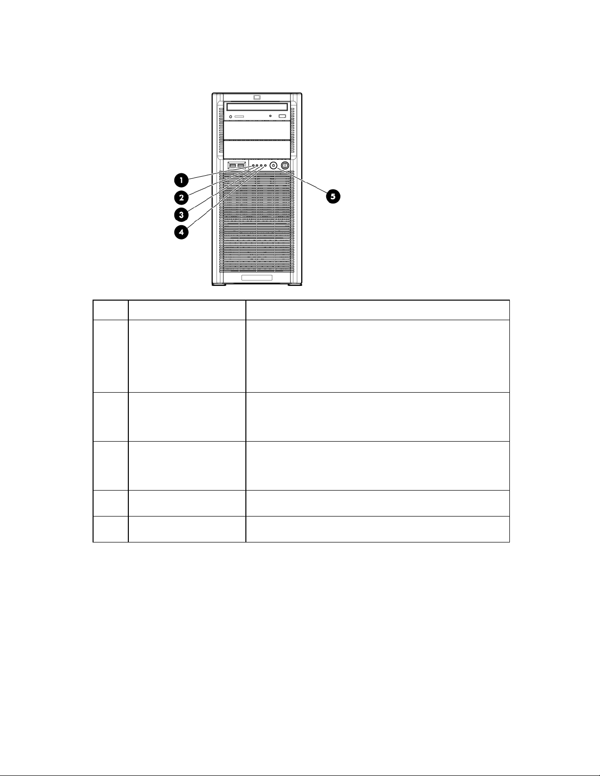
Front panel LEDs and buttons
NIC 1 link/activity LED
Green or flashing green = Activity exists.
Item Description Status
1
2
3
4
5
System health LED Green = System health is normal.
Amber = System health is degraded. To identify the component in a
degraded state, see "System board LEDs (on page 13)."
Red = System health is critical. To identify the component in a critical
state, see "System board LEDs (on page 13)."
Off = System health is normal (when in standby mode).
Off = No activity exists.
If power is off, view the LEDs on the RJ-45 connector. See "Rear panel
LEDs and buttons (on page 10)."
NIC 2 link/activity LED Green = Link exists.
Off = No link exists.
If power is off, view the LEDs on the RJ-45 connector. See "Rear panel
LEDs and buttons (on page 10)."
Drive activity LED Green = Drive activity is normal.
Off = No drive activity exists.
Power On/Stand by button
and system power LED
Green = Power is on.
Amber = System is in standby mode.
Component identification 8
Page 9

Rear panel components
Power supply 1
Item Description
1
2
3
4
5
6
7
8
9
10
11
12
13
14
15
16
Dedicated iLO 2 management port (optional)
Serial connector
10/100/1000 NIC 2 connector
10/100/1000 NIC 1 connector/shared iLO 2
management port
Mouse connector
Power supply blank
Slot 1 PCI-X*
Slot 2 PCI-X*
Slot 3 PCIe1 x8 (1)
Slot 4 PCIe2 x16 (16, 8, 4, 2, 1)
Slot 5 PCIe2 x8 (4, 2, 1)
Slot 6 PCIe2 x8 (4, 2, 1)
Video connector
USB connectors (2)
Keyboard connector
Component identification 9
Page 10
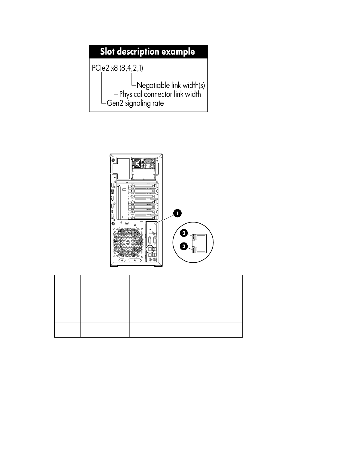
*Slots 1 and 2 are available only when an optional PCI-X extender board is installed.
Rear panel LEDs and buttons
Item Description Status
1
2
3
UID button/LED Blue = Activated
Flashing = System is being managed remotely.
Off = Deactivated
NIC/iLO 2 activity Green or flashing green = Activity exists.
Off = No activity exists.
NIC/iLO 2 link Green = Link exists.
Off = No link exists.
Component identification 10
Page 11
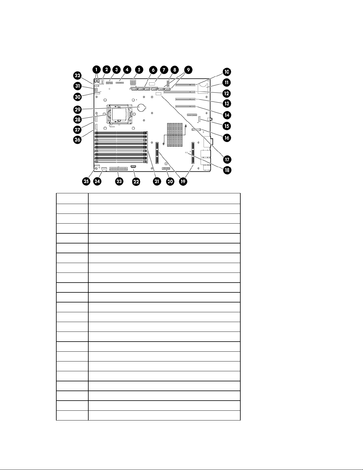
System board components
SATA connectors 1-4 (hard drive)
SD card slot
Processor 1 DIMMs (1-9)
For this server, some system board slots and connectors are reserved.
Item Description
1
2
3
4
5
6
7
8
9
10
11
12
13
14
15
16
17
18
19
20
21
22
Hard drive backplane connectors (2)
Internal USB connector
Redundant power supply connector
Front panel connector
Reserved
Hard drive LED connector
System maintenance switch
SATA connectors 5-6 (optical drive)
Slot 3 PCIe1 x8 (1)
Slot 4 PCIe2 x16 (16, 8, 4, 2, 1)
Slot 5 PCIe2 x8 (4, 2, 1)
Slot 6 PCIe2 x8 (4, 2, 1)
Fan 6 connector
Dedicated iLO 2 module connector (optional)
Hard drive backplane connector
NMI jumper
Processor board connectors
TPM connector
USB connector
Component identification 11
Page 12

Item Description
23
24
25
26
27
28
29
30
31
32
* The server supports one optical drive that can be connected to either SATA connector 5 or SATA connector 6.
System power connector
Fan 1 connector
Fan 1.5 or 2 connector
Fan 3 connector
Reserved
Processor socket 1 (populated)
Battery
Reserved
Power connector
Front USB connector
System maintenance switch
Position Default Function
S1
S2
S3
S4
S5
S6
S7
S8
Off Off = iLO 2 security is enabled.
On = iLO 2 security is disabled.
Off Off = Normal operation
On = RBSU will not commit any
configuration changes.*
Off Reserved
Off Reserved
Off Off = Power-on password enabled
On = Power-on password disabled*
Off Off = Normal operation
On = BIOS will clear CMOS and
NVRAM.*
Off Reserved
Off Reserved
* "On" activates the function.
Component identification 12
Page 13

NMI functionality
An NMI crash dump enables administrators to create crash dump files when a system is hung and not
responding to traditional debug mechanisms.
Crash dump log analysis is an essential part of diagnosing reliability problems, such as hangs in operating
systems, device drivers, and applications. Many crashes freeze a system, and the only available action for
administrators is to cycle the system power. Resetting the system erases any information that could support
problem analysis, but the NMI feature preserves that information by performing a memory dump before a
hard reset.
To force the OS to invoke the NMI handler and generate a crash dump log, the administrator can do any of
the following:
• Short the NMI jumper pins
• Press the NMI switch
• Use the iLO Virtual NMI feature
For additional information, see the whitepaper on the HP website
(http://h20000.www2.hp.com/bc/docs/support/SupportManual/c00797875/c00797875.pdf).
System board LEDs
Item LED description Status
1
2
3
4
Processor failure Amber = Processor has failed.
Off = Normal
Fan 6 failure Amber = Fan has failed or is missing.
Off = Normal
Power supply Off = No AC power or failed power supply
Green = Power supply is on and is functioning.
Overtemperature Amber = System has reached a cautionary or
critical temperature level.
Component identification 13
 Loading...