

Page 1

HP ProLiant ML310e Gen8 Server
Part Number: 682266-001
User Guide
Abstract
This document is for the person who installs, administers, and troubleshoots servers and storage systems. HP assumes you are qualified in the
servicing of computer equipment and trained in recognizing hazards in products with hazardous energy levels.
September 2012
Edition: 1
Page 2

© Copyright 2012 Hewlett-Packard Development Company, L.P.
The information contained herein is subject to change without notice. The only warranties for HP products and services are set forth in the express
warranty statements accompanying such products and services. Nothing herein should be construed as constituting an additional warranty. HP shall
not be liable for technical or editorial errors or omissions contained herein.
Microsoft® and Windows® are U.S. registered trademarks of Microsoft Corporation.
Bluetooth® is a trademark owned by its proprietor and used by Hewlett-Packard Company under license.
Intel® Xeon®, Pentium®, Celeron®, and Intel® Core™ are trademarks of Intel Corporation in the U.S. and other countries.
Page 3

Contents
Component identification ............................................................................................................... 7
Front panel components ............................................................................................................................. 7
Front panel LEDs and buttons ............................................................................................................ 8
Rear panel components .............................................................................................................................. 9
Rear panel LEDs and buttons ........................................................................................................... 10
System board components ........................................................................................................................ 11
DIMM slot locations ....................................................................................................................... 12
PCIe expansion slot definitions ........................................................................................................ 12
System maintenance switch ............................................................................................................. 12
NMI header .................................................................................................................................. 13
Drive numbering ..................................................................................................................................... 14
Drive LED definitions ................................................................................................................................ 15
FBWC module LED definitions ................................................................................................................... 16
Fan locations .......................................................................................................................................... 17
T-10/T-15 Torx screwdriver ...................................................................................................................... 17
Operations ................................................................................................................................. 18
Power up the server ................................................................................................................................. 18
Power down the server ............................................................................................................................. 18
Unlock the tower bezel ............................................................................................................................ 19
Remove the tower bezel ........................................................................................................................... 19
Install the tower bezel .............................................................................................................................. 19
Remove the access panel.......................................................................................................................... 20
Install the access panel............................................................................................................................. 21
Remove the air baffle ............................................................................................................................... 21
Install the air baffle .................................................................................................................................. 22
Setup ......................................................................................................................................... 24
Optional installation services .................................................................................................................... 24
Rack planning resources........................................................................................................................... 24
Optimum environment .............................................................................................................................. 24
Space and airflow requirements ...................................................................................................... 25
Temperature requirements ............................................................................................................... 25
Power requirements ....................................................................................................................... 25
Electrical grounding requirements .................................................................................................... 25
Server warnings and cautions ................................................................................................................... 26
Rack warnings ........................................................................................................................................ 26
Identifying the contents of the server shipping carton .................................................................................... 27
Installing hardware options ....................................................................................................................... 27
Installing the server into the rack ................................................................................................................ 27
Installing the operating system................................................................................................................... 28
Powering on and selecting boot options ..................................................................................................... 29
Registering the server ............................................................................................................................... 29
Hardware options installation ....................................................................................................... 30
Introduction ............................................................................................................................................ 30
Drive options .......................................................................................................................................... 30
Contents 3
Page 4

Drive installation guidelines ............................................................................................................ 30
Installing a non-hot-plug drive .......................................................................................................... 30
Installing a hot-plug drive ................................................................................................................ 32
Drive cage options .................................................................................................................................. 33
Four-bay LFF hot-plug drive backplane option .................................................................................... 33
Eight-bay SFF hot-plug drive cage option .......................................................................................... 37
Controller options .................................................................................................................................... 39
Installing a storage controller .......................................................................................................... 39
Installing the FBWC module and capacitor pack ............................................................................... 40
Optical drive option ................................................................................................................................ 42
Memory options ...................................................................................................................................... 44
HP SmartMemory .......................................................................................................................... 45
DIMM identification ....................................................................................................................... 45
Single-rank and dual-rank DIMMs .................................................................................................... 46
Memory subsystem architecture ....................................................................................................... 46
ECC memory ................................................................................................................................ 46
General DIMM slot population guidelines ......................................................................................... 47
Installing a DIMM .......................................................................................................................... 47
Expansion board options .......................................................................................................................... 48
Dedicated iLO management port option ..................................................................................................... 52
Enabling the dedicated iLO management port ................................................................................... 53
HP Trusted Platform Module option ............................................................................................................ 54
Installing the Trusted Platform Module board ..................................................................................... 54
Retaining the recovery key/password .............................................................................................. 56
Enabling the Trusted Platform Module ............................................................................................... 56
RPS enablement option ............................................................................................................................ 57
Cabling ..................................................................................................................................... 61
Cabling overview .................................................................................................................................... 61
Storage cabling ...................................................................................................................................... 61
Four-bay LFF drive cabling .............................................................................................................. 61
Eight-bay SFF drive cabling ............................................................................................................. 63
Media drive cabling ................................................................................................................................ 64
Power supply cabling............................................................................................................................... 65
Nonredundant power supply cabling ............................................................................................... 65
Redundant power supply cabling ..................................................................................................... 65
Capacitor pack cabling ........................................................................................................................... 66
Software and configuration utilities ............................................................................................... 67
Server mode ........................................................................................................................................... 67
Server QuickSpecs .................................................................................................................................. 67
HP iLO Management Engine ..................................................................................................................... 67
HP iLO ......................................................................................................................................... 67
Intelligent Provisioning .................................................................................................................... 69
HP Insight Remote Support software ................................................................................................. 71
Scripting Toolkit ............................................................................................................................ 71
HP Service Pack for ProLiant ..................................................................................................................... 72
HP Smart Update Manager ............................................................................................................. 72
HP ROM-Based Setup Utility ..................................................................................................................... 72
Using RBSU .................................................................................................................................. 73
Auto-configuration process .............................................................................................................. 73
Boot options ................................................................................................................................. 74
Re-entering the server serial number and product ID ........................................................................... 74
Utilities and features ................................................................................................................................ 74
Contents 4
Page 5

Array Configuration Utility .............................................................................................................. 74
Option ROM Configuration for Arrays ............................................................................................. 75
ROMPaq utility .............................................................................................................................. 76
Automatic Server Recovery ............................................................................................................. 76
USB support .................................................................................................................................. 76
Redundant ROM support ................................................................................................................ 76
Keeping the system current ....................................................................................................................... 77
Drivers ......................................................................................................................................... 77
Software and firmware ................................................................................................................... 77
Version control .............................................................................................................................. 77
HP Operating Systems and Virtualization Software Support for ProLiant Servers ..................................... 78
Change control and proactive notification ........................................................................................ 78
Troubleshooting .......................................................................................................................... 79
Troubleshooting resources ........................................................................................................................ 79
System battery replacement .......................................................................................................... 80
Regulatory compliance notices ..................................................................................................... 82
Regulatory compliance identification numbers ............................................................................................. 82
Federal Communications Commission notice ............................................................................................... 82
FCC rating label ............................................................................................................................ 82
FCC Notice, Class A Equipment ...................................................................................................... 82
FCC Notice, Class B Equipment ...................................................................................................... 82
Declaration of conformity for products marked with the FCC logo, United States only ....................................... 83
Modifications .......................................................................................................................................... 83
Cables ................................................................................................................................................... 83
Canadian notice (Avis Canadien) .............................................................................................................. 83
European Union regulatory notice ............................................................................................................. 84
Disposal of waste equipment by users in private households in the European Union ......................................... 84
Japanese notice ...................................................................................................................................... 85
BSMI notice ............................................................................................................................................ 85
Korean notice ......................................................................................................................................... 85
Chinese notice ........................................................................................................................................ 86
Vietnam compliance marking notice .......................................................................................................... 86
Ukraine notice ........................................................................................................................................ 86
Laser compliance .................................................................................................................................... 86
Battery replacement notice ........................................................................................................................ 87
Taiwan battery recycling notice ................................................................................................................. 87
Power cord statement for Japan ................................................................................................................. 87
Acoustics statement for Germany (Geräuschemission) .................................................................................. 88
Electrostatic discharge ................................................................................................................. 89
Preventing electrostatic discharge .............................................................................................................. 89
Grounding methods to prevent electrostatic discharge .................................................................................. 89
Specifications ............................................................................................................................. 90
Environmental specifications ..................................................................................................................... 90
Server specifications ................................................................................................................................ 90
Power supply specifications ...................................................................................................................... 90
HP 350 W 4U Factory Integrated Power Supply ................................................................................ 91
HP 460 W CS Gold Hot-plug Power Supply (92% efficiency) .............................................................. 91
Hot-plug power supply calculations .................................................................................................. 91
Support and other resources ........................................................................................................ 92
Contents 5
Page 6

Before you contact HP .............................................................................................................................. 92
HP contact information ............................................................................................................................. 92
Customer Self Repair ............................................................................................................................... 92
Acronyms and abbreviations ...................................................................................................... 100
Documentation feedback ........................................................................................................... 104
Index ....................................................................................................................................... 105
Contents 6
Page 7
Component identification
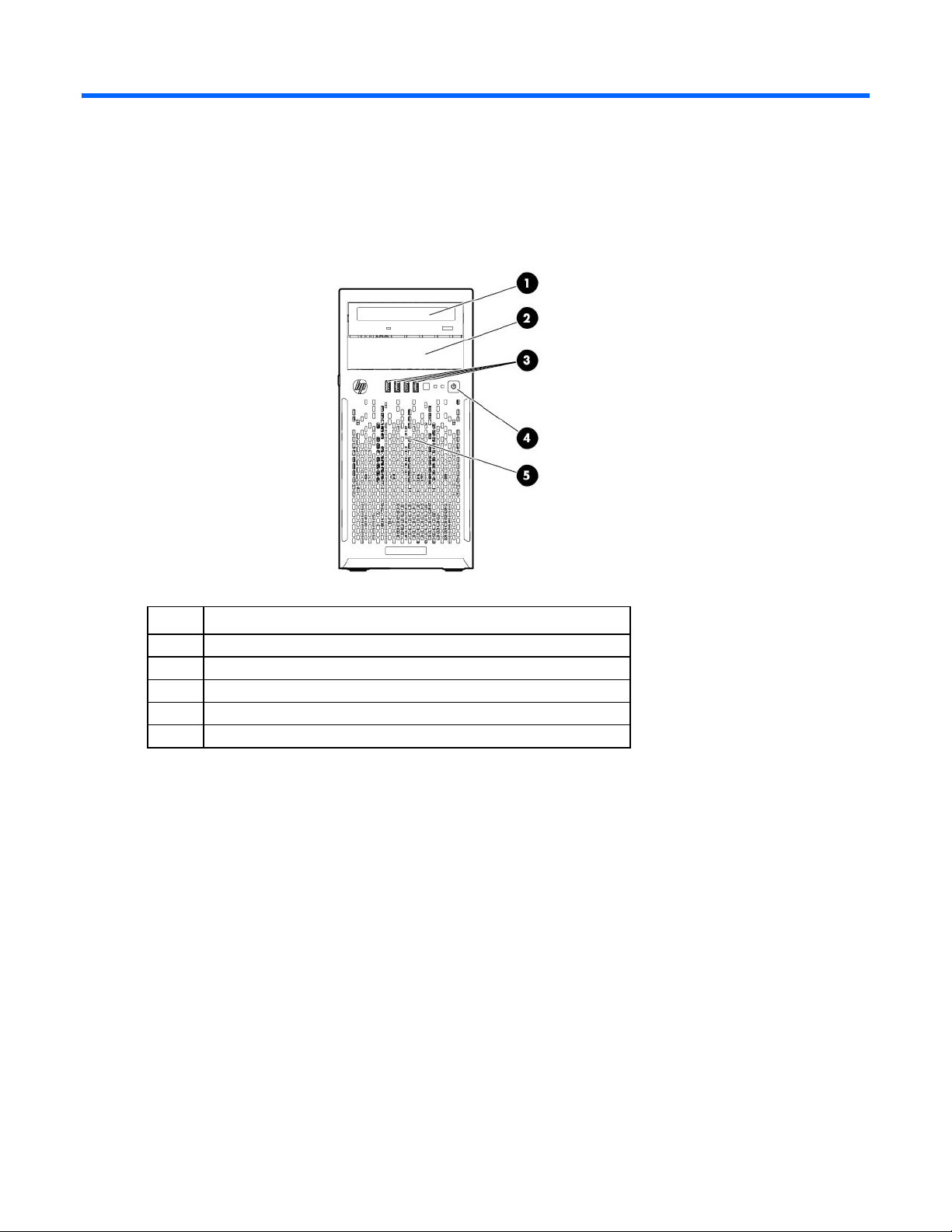
Media drive bay
Front panel components
Item Description
1
2
3
4
5
Optical drive (optional)
USB connectors
Power On/Standby button and system power LED
Drive bays (inside)
Component identification 7
Page 8

Front panel LEDs and buttons
Item Description Status
1
2
3
4
UID LED button Blue = Identification is activated
Flashing blue = System is being managed remotely
Off = Identification is deactivated
Health LED Green = Normal (system on)
Flashing amber = System health is degraded
Flashing red = System health is critical
Off = Normal (system off)
NIC status LED Green = Linked to network
Flashing green = Network activity
Off = No network link
Power On/Standby button
and system power LED
Green = Normal (system on)
Flashing green = Waiting for power
Amber = System in standby, but power is still applied
Off = Power cord is not attached or power supply failure
Component identification 8
Page 9

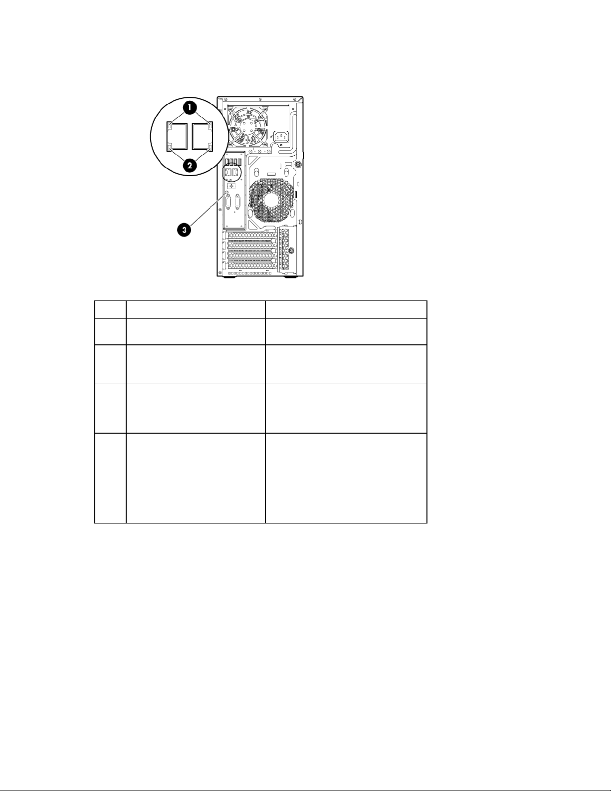
Rear panel components
Item Description
1
2
3
4
5
6
7
8
9
10
11
12
Non-hot-plug power supply
Slot 4 PCIe x16 (8, 4, 1)*
Slot 3 PCIe x8 (8, 4, 1)*
Slot 2 PCIe x8 (4, 1)*
Slot 1 PCIe x4 (1)*
Expansion slot cover retainer
Serial connector
Video connector
Dedicated iLO management port (optional)
NIC 1/shared iLO management connector
NIC connector 2
USB connectors
* For more information on the expansion slot specifications, see "PCIe expansion slot definitions (on page
12)."
Component identification 9
Page 10
Rear panel LEDs and buttons
NIC status LED
Green = Activity exists
•
•
•
•
Item Description Status
1
2
3
4
NIC link LED Green = Link exists
Off = No link exists
Flashing green = Activity exists
Off = No activity exists
UID LED button Blue = Identification is activated
Flashing blue = System is being
managed remotely
Off = Identification is deactivated
Power supply LED (for hot-plug HP
CS power supplies only)*
Green = Normal
Off = One or more of the following
conditions exists:
Power is unavailable
Power supply failed
Power supply is in standby mode
Power supply error
*Not shown
Component identification 10
Page 11

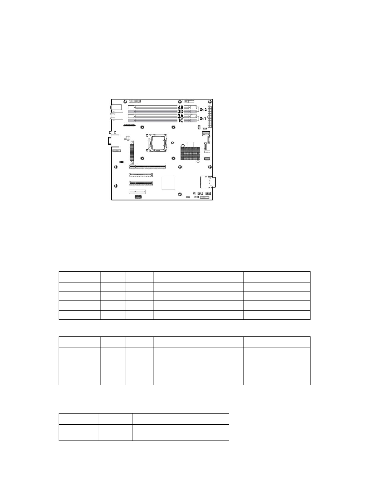
System board components
Internal USB connector
Dedicated iLO module connector
Item Description
1
2
3
4
5
6
7
8
9
10
11
12
13
14
15
16
17
18
19
20
21
22
23
24
25
26
RPS connector
Processor socket
System battery
24-pin power supply connector
Mini-SAS connector
SATA connectors
Internal USB cable connector
SD card slot
Front USB connector 2
Front USB connector 1
Front panel LED connector
Fan connector 2
Reserved
Ambient thermal sensor connector
NMI header
System maintenance switch
Slot 1 PCIe x4 (1)*
Slot 2 PCIe x8 (4, 1)*
Slot 3 PCIe x8 (8, 4, 1)*
Slot 4 PCIe x16 (8, 4, 1)*
Fan connector 1
TPM connector
4-pin power supply connector
DIMM slots
Component identification 11
Page 12
* For more information on the expansion slot specifications, see "PCIe expansion slot definitions (on page
12)."
DIMM slot locations
DIMM slots are numbered sequentially (1 through 4) for the processor. The supported AMP modes use the
letter assignments for population guidelines.
PCIe expansion slot definitions
The transfer rate of the PCIe expansion slots 3 and 4 depends on the processor model installed. The slots can
either run in PCIe2 (5 GT/s) or PCIe3 (8 GT/s) rate.
• Intel Xeon Processor E3-xxxx Series, Intel Core i3 Processor Series, Intel Pentium G2120, and Intel
Celeron G540
Slot number Type Length Height Connector link width Negotiable link width
1
2
3
4
• Intel Xeon Processor E3-xxxxV2 Series
Slot number Type Length Height Connector link width Negotiable link width
1
2
3
4
PCIe2 Half Full x4 x1
PCIe2 Full Full x8 x4
PCIe2 Full Full x8 x8
PCIe2 Full Full x16 x8
PCIe2 Half Full x4 x1
PCIe2 Full Full x8 x4
PCIe3 Full Full x8 x8
PCIe3 Full Full x16 x8
System maintenance switch
Switch Default Function
1
Off Off = No function
On = iLO security is disabled
Component identification 12
Page 13
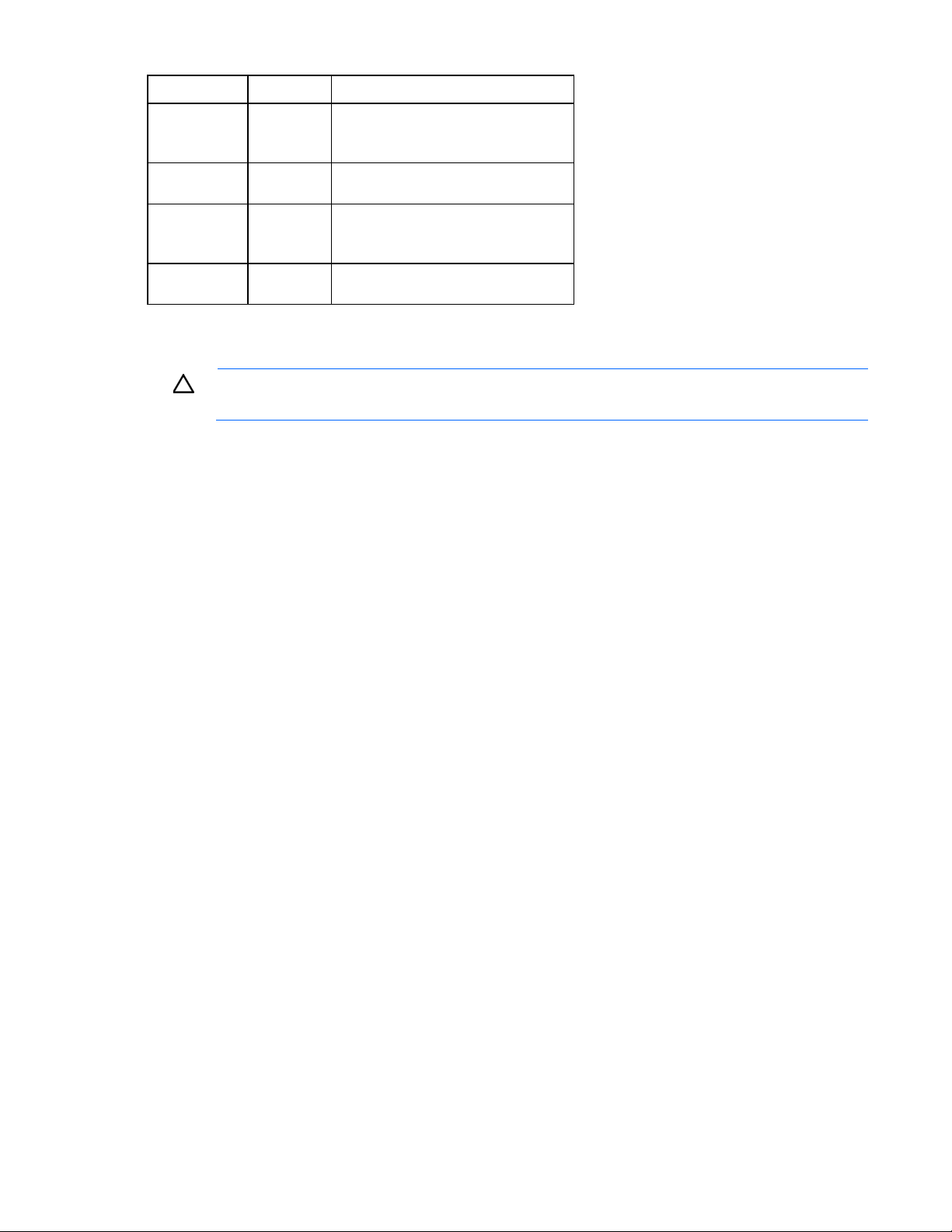
Switch Default Function
2
5
6
3, 4, 7, 8, 9,
10, 11, 12
When the system maintenance switch position 6 is set to the On position, the system is prepared to erase all
system configuration settings from both CMOS and NVRAM.
CAUTION: Clearing CMOS and/or NVRAM deletes configuration information. Be sure to
properly configure the server or data loss could occur.
NMI header
Off Off = System configuration can be
changed
On = System configuration is locked
Off Off = Power-on password is enabled
On = Power-on password is disabled
Off Off = No function
On = ROM reads configuration as
invalid
— Reserved
The NMI header enables administrators to perform a memory dump before performing a hard reset. Crash
dump analysis is an essential part of eliminating potential reliability issues, such as hangs or crashes in
operating systems, device drivers, and applications. Many crashes can freeze a system, requiring you to
perform a hard reset. Resetting the system erases any information that supports root cause analysis.
Systems running Microsoft® Windows® experience a blue-screen trap when the OS crashes. When this
happens, Microsoft® recommends that system administrators perform an NMI event by temporarily shorting
the NMI header with a jumper. The NMI event enables a hung system to become responsive again.
For additional information, see the HP website
(http://h20000.www2.hp.com/bc/docs/support/SupportManual/c00797875/c00797875.pdf).
Component identification 13
 Loading...