

Page 1
ML-2240 & ML-2245 & ML-1640 Series training
ML-2240 & ML-2245 & ML-1640 Series training
February 2008
February 2008
Page 2
Agenda
Agenda
1. Overview
2. Block & Connection Diagram
3. Schematic – Key concept
4. Cover Open Sensing
5. Q&A
Page 3
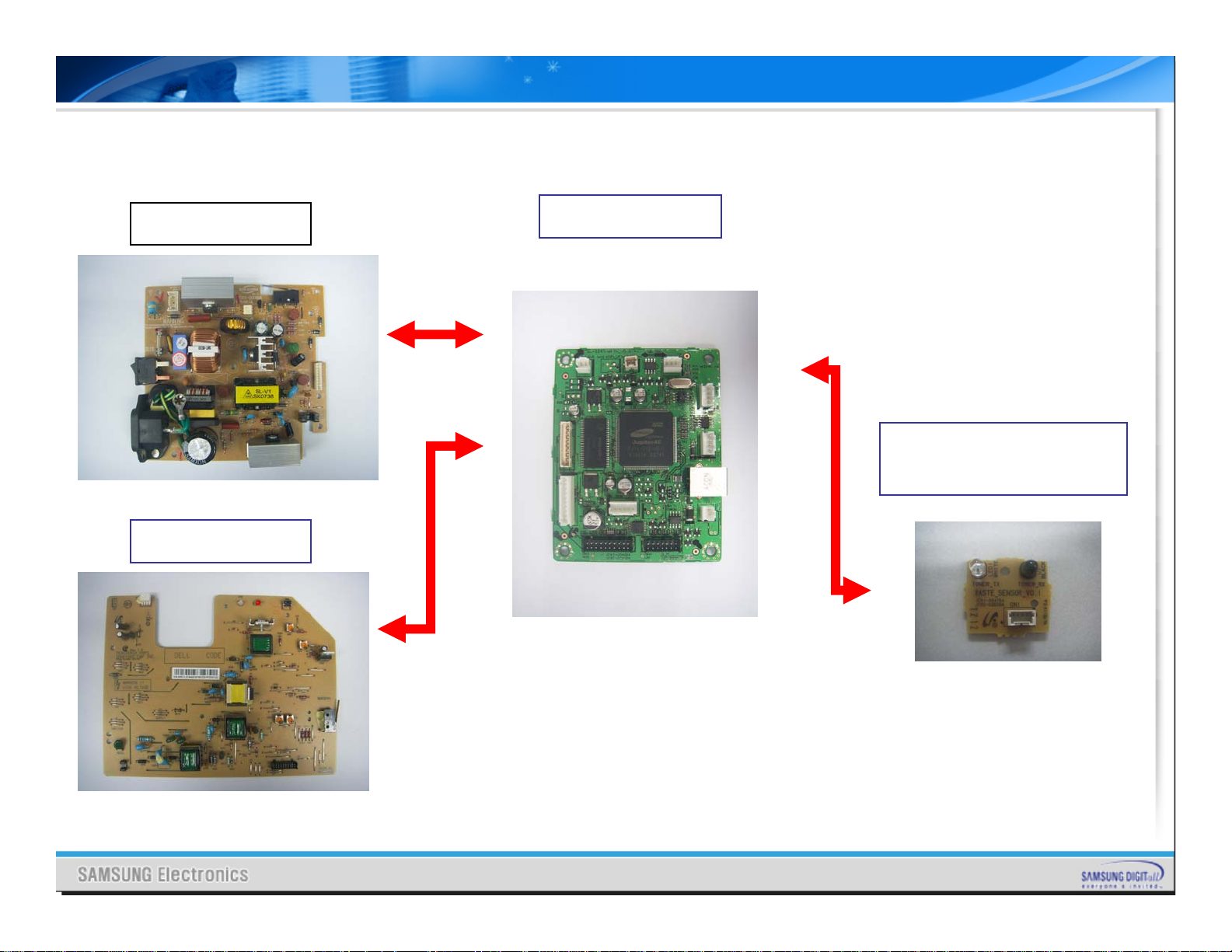
Ⅰ. Introduction
1-1. Overview(ML–2240 & ML-2245)
SMPS
HVPS
Main Board
Waste Sensor
(Only ML-2245)
Page 4
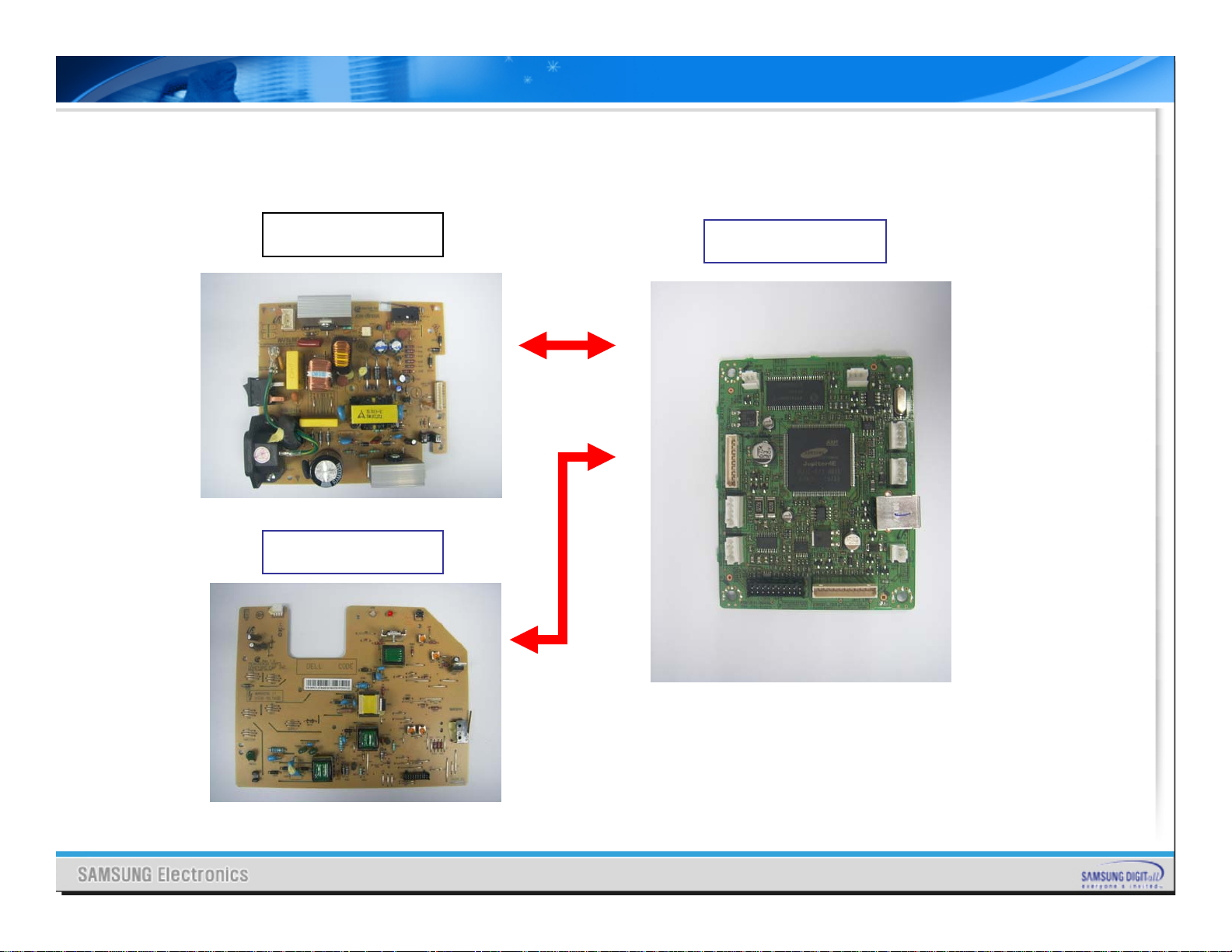
Ⅰ. Introduction
1-2. Overview(ML–1640)
SMPS
HVPS
Main Board
Page 5
Ⅰ. Introduction
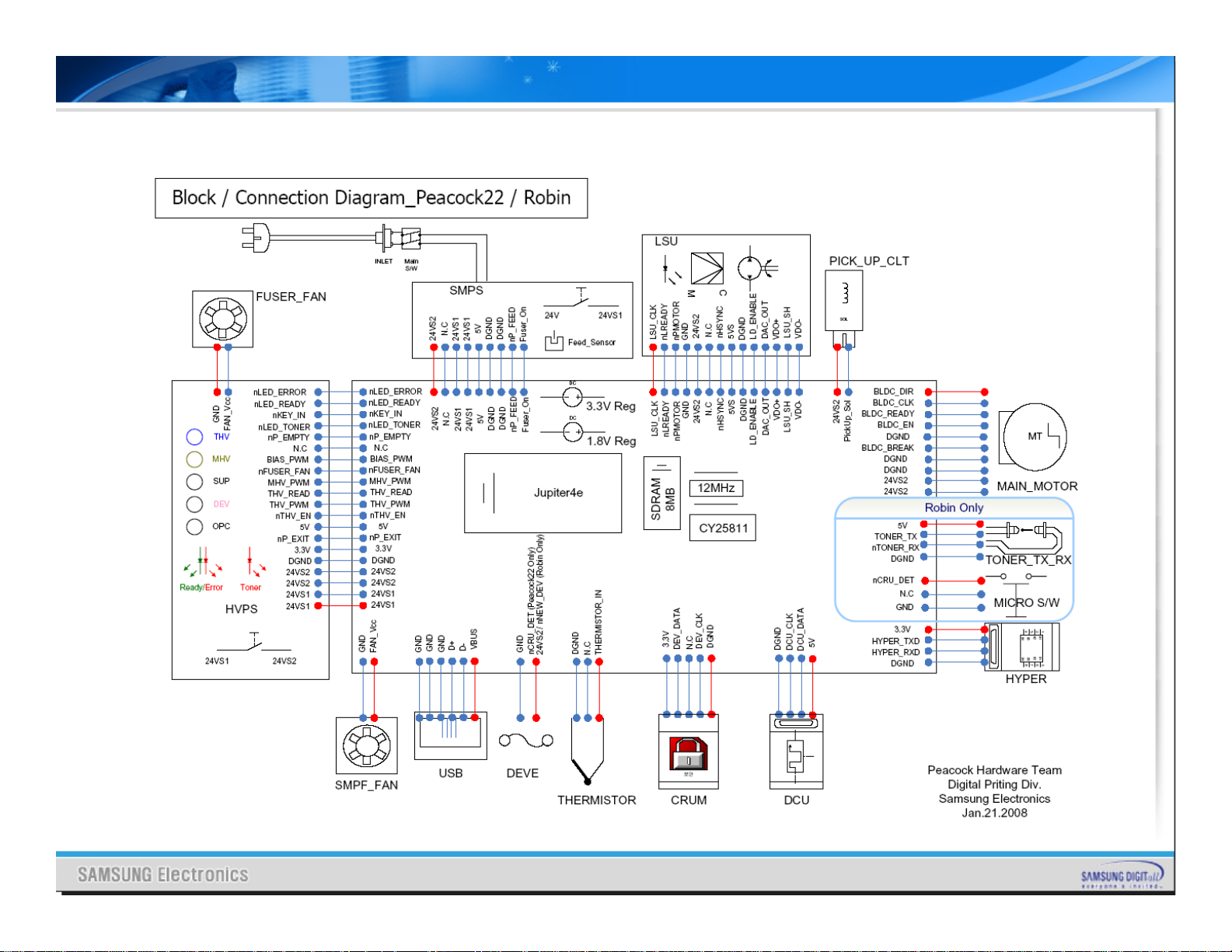
2. Block & Connection Diagram of ML-2240 & 2245
Page 6
Ⅰ. Introduction
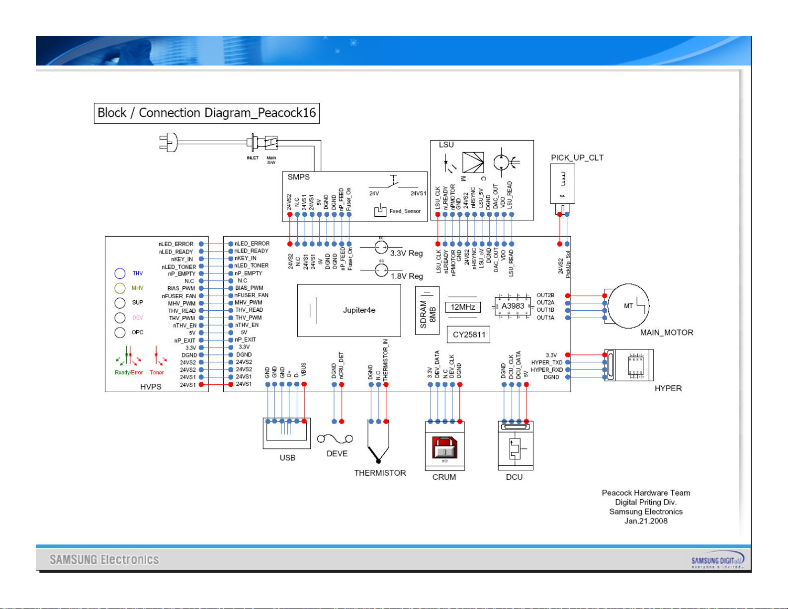
2-2. Block Diagram of ML-1640
Page 7
Ⅰ. Introduction
3. Schematic - Key Concepts
3-1. Main PBA – 1(ML-2240&2245)
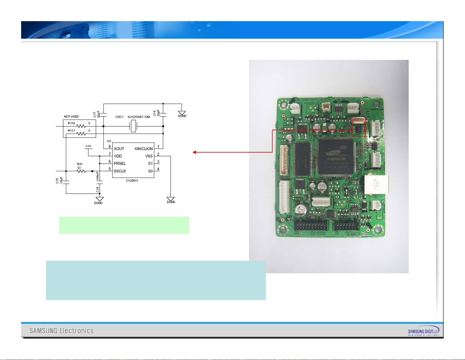
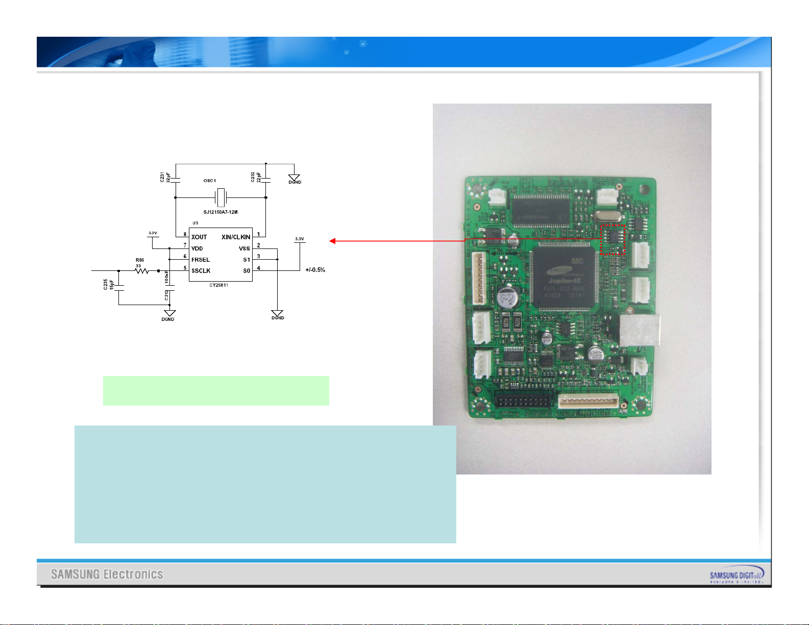
Main Clock and SSCG
¾ SSCG means Spread Spectrum Clock Generator
¾ Apply SSCG(Spread Spectrum Clock Generator) on the Main Clock.
¾ Main Clock frequency is 12MHz and Video Clock is 14.75MHz.
¾ CPU makes video clock using internal PLL block.
¾ It doesn’t need extra Oscillator for video clock.
Page 8
Ⅰ. Introduction
3-1. Main PBA – 2(ML-2240&2245)
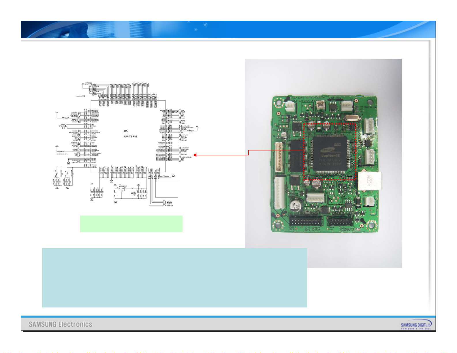
CPU – Jupiter4e
¾ Jupiter4e is developed using ARM940T 32Bit RISC embedded processor core.
¾ 1.8V internal, 3.3V external(I/O boundary) Voltage used.
¾ Image processor included(GDI only).
¾ On-Chip clock genarator with internal PLL.
¾ Operating frequency is 75MHz ( converting 10MHz main clock to 75MHz operating
clock using internal PLL )
¾ It has Built in Flash Memory : 4MBits (128Kx32bits)
¾ 4Mbit is 0.5MByte. It is small capacity. So we can not store many function in it.
Page 9
Ⅰ. Introduction
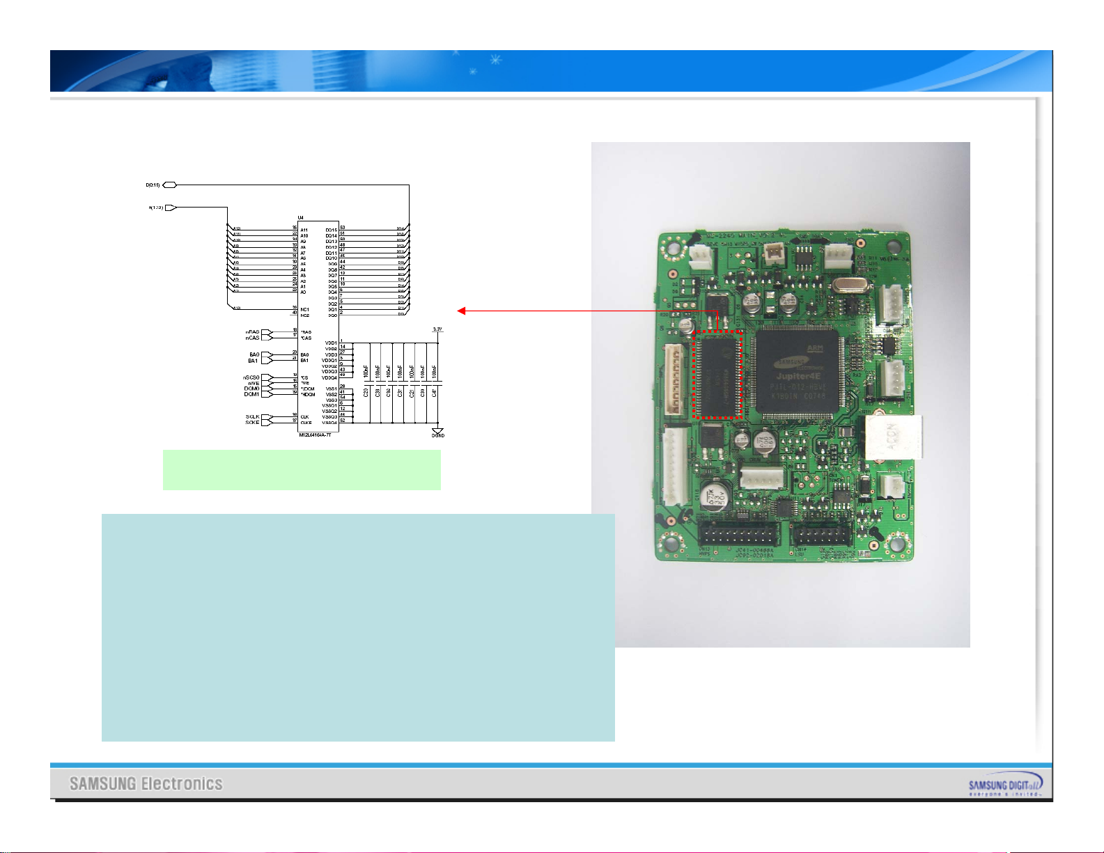
3-1. Main PBA – 3(ML-2240&2245)
SDRAM – 8MB * 1ea
¾ SDRAM(Max operating frequency : 133MHz) used and SDRAM has
8MByte memory capacity.
¾ SDRAM operates 75MHz which is the same as CPU’s operating
frequency.
¾ F/W program code had been stored in the Built-in Flash Memory
when Main PBA assembled , and the program code can be
upgraded by user.
¾ When upgrading F/W, never turn off the power until completing
upgrade process.
¾ If user turn off the power while upgrading F/W, the program code
will be conflicted and the machine will not work.
¾ If above situation occurs, replace the Main PBA.
¾ After downloading, set automatically conduct power off/on.
Page 10

Ⅰ. Introduction
3-1. Main PBA – 4(ML-2240&2245)
EEPROM
Chip Select InputCS
Serial ClockSK
Serial Data OutputDO
Serial Data InputDI
Organization SelectORG
Supply VoltageVCC
GroundGND
¾ ML-2240 has EEPROM in order to store environmental data, total
page count data, dot counter data, etc…
¾ M93C66(4Kbit) EEPROM device is used.
¾ Read/Write operation is activated when the machine states go idle.
¾ While printing, Copying, scanning, EEPROM read/write operation
not activated.
¾ Because of above reason, if user turn the power off right after
printed page exit, there is no time for writing newer data that
results dot count and page count data not updated.
Page 11

Ⅰ. Introduction
3-1. Main PBA – 5(ML-2240&2245)
Main Motor Control
(BLDC)
¾ ML-2240 drives the engine motor using BLDC Motor.
¾ BLDC Motor includes the motor driver IC and extra
circuits for driving the engine motor.
¾ The main board controls only 3 signals (ex. Enable ,
Ready , CLK)
Page 12
Ⅰ. Introduction
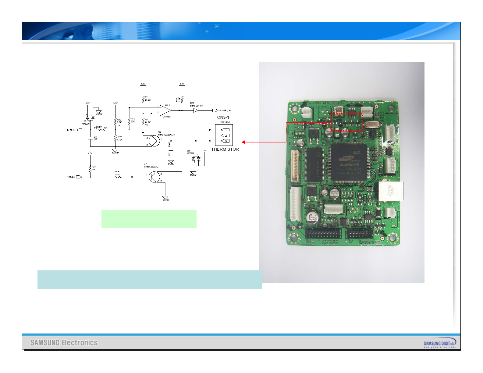
3-1. Main PBA – 6(ML-2240&2245)
Fuser Control
¾ ML-2240 has one heat lamp.
¾ Main controller has a signal to control the lamp.
Page 13
Ⅰ. Introduction
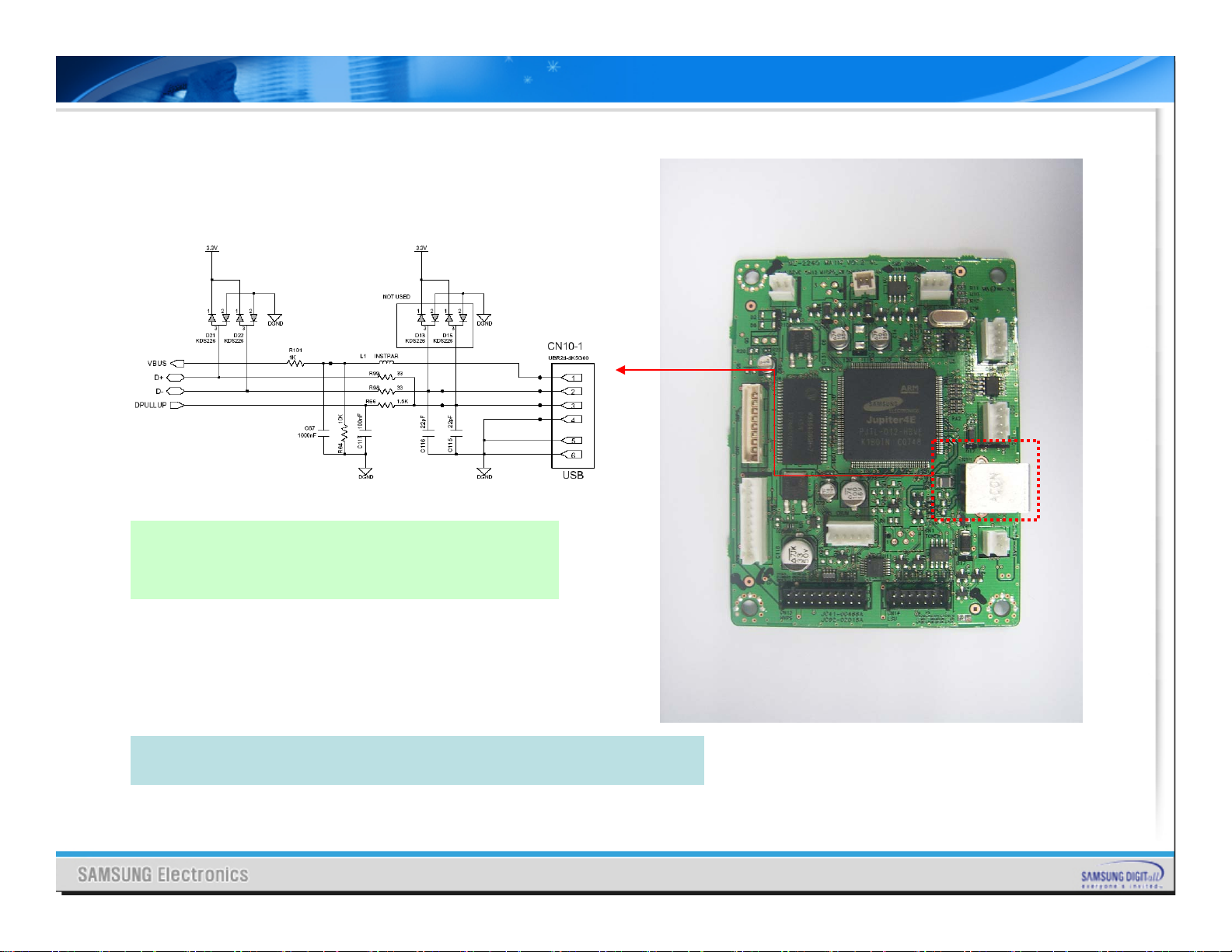
3-1. Main PBA – 7(ML-2240&2245)
USB 1.1
(Compatible with USB2.0)
¾ ML-2240 uses internal USB1.1 in Jupiter4e.
¾ USB2.0 full speed supported.
Page 14

Ⅰ. Introduction
3-1. Main PBA – 8(Only ML-2245)
Toner Waste-Sensor
¾ ML-2245 uses Waste sensor PBA to sense remaing Toner.
¾ Developer Unit of ML-2245 is separated into Toner cartridge and
Imaging Unit.
(Developer Unit of ML-2245 & ML-1640 is not separated.)
¾ So remaining toner of Toner cartridge must be sensed.
Page 15
Ⅰ. Introduction
3-2. Main PBA – 1(ML-1640)
Main Clock and SSCG
¾ SSCG means Spread Spectrum Clock Generator
¾ Apply SSCG(Spread Spectrum Clock Generator) on the Main Clock.
¾ Main Clock frequency is 12MHz and Video Clock is 20.75MHz.
¾ CPU makes video clock using internal PLL block.
¾ It doesn’t need extra Oscillator for video clock.
¾ The SSCG of the main clock has +/-0.6% spread spectrum in order
to reduce EMI.
¾ The SSCG of the video clock part has no spread because of image
quality, but still effective for reducing EMI.
Page 16

Ⅰ. Introduction
3-2. Main PBA – 2(ML-1640)
CPU – Jupiter4e
¾ Jupiter4e is developed using ARM940T 32Bit RISC embedded processor core.
¾ 1.8V internal, 3.3V external(I/O boundary) Voltage used.
¾ Image processor included(GDI only).
¾ On-Chip clock genarator with internal PLL.
¾ Operating frequency is 75MHz ( converting 10MHz main clock to 75MHz operating
clock using internal PLL )
¾ It has Built in Flash Memory : 4MBits (128Kx32bits)
¾ 4Mbit is 0.5MByte. It is small capacity. So we can not store many function in it.
Page 17

Ⅰ. Introduction
3-2. Main PBA – 3(ML-1640)
SDRAM – 8MB * 1ea
¾ SDRAM(Max operating frequency : 133MHz) used and SDRAM has
8MByte memory capacity.
¾ SDRAM operates 75MHz which is the same as CPU’s operating
frequency.
¾ F/W program code had been stored in the Built-in Flash Memory
when Main PBA assembled , and the program code can be
upgraded by user.
¾ When upgrading F/W, never turn off the power until completing
upgrade process.
¾ If user turn off the power while upgrading F/W, the program code
will be conflicted and the machine will not work.
¾ If above situation occurs, replace the Main PBA.
¾ After downloading, set automatically conduct power off/on.
Page 18

Ⅰ. Introduction
3-2. Main PBA – 4(ML-1640)
EEPROM
Chip Select InputCS
Serial ClockSK
Serial Data OutputDO
Serial Data InputDI
Organization SelectORG
Supply VoltageVCC
GroundGND
¾ ML-1640 has EEPROM in order to store environmental data, total
page count data, dot counter data, etc…
¾ M93C66(4Kbit) EEPROM device is used.
¾ Read/Write operation is activated when the machine states go idle.
¾ While printing, Copying, scanning, EEPROM read/write operation
not activated.
¾ Because of above reason, if user turn the power off right after
printed page exit, there is no time for writing newer data that
results dot count and page count data not updated.
Page 19

Ⅰ. Introduction
3-2. Main PBA – 5(ML-1640)
Main Motor Control
(A3983)
¾ ML-1640 drives the engine motor using Stepping motor unlike
ML-2240.
¾ A3983 is a stepping motor driver IC.
¾ A3983 has the ability control the output current which gives the
smoothing action to the motor in the starting period.
¾ But main motor can be driven forward only full-step resolution in
ML-1640.
Page 20

Ⅰ. Introduction
3-2. Main PBA – 6(ML-1640)
Fuser Control
¾ ML-2240 has one heat lamp.
¾ Main controller has a signal to control the lamp.
Page 21

Ⅰ. Introduction
3-2. Main PBA – 7(ML-1640)
USB 1.1
(Compatible with USB2.0)
¾ ML-1640 uses internal USB1.1 in Jupiter4e.
¾ USB2.0 full speed supported.
Page 22

II. Summary of Product
3-3. SMPS PBA
ML-2240/2245
Heat Lamp
Connector
AC Input
Socket
Rear Cover Open
S/W
Main <-> SMPS
Connector
Paper Feed Sensor
¾ The output current of 5V and 24V is
- 5V : 0.7A
- 24V : 1.5A (in ML-1640)
2.0A (in ML-2240,2245)
¾ On the SMPS board, Paper feed sensor
exists.
¾ The capacity of one heat lamp is
600W in ML-1640 &
750W in ML-2240,2245.
ML-1640
Page 23

II. Summary of Product
3-4. HVPS PBA
LEDs & tact switch
-100VOPC
-1300VMHV
-550VSUP
-350VDEV
Main <-> HVPS
Connector
Front Cover Open
S/W
¾ HVPS board supply high voltage for developing Process.
¾ High Voltage controlled by PWM signal from CPU.
¾ LEDs & tact switch exists on HVPS instead of OPE PBA.
THV
+1,300V
-1,000V
Page 24

II. Summary of Product
4. Cover Open Sensing
Two cover open switches are near front cover & rear cover.
If two switches open, 24VS2 for DC fan, main motor, polygon
motor part of LSU and high voltage of HVPS and 5VS for LSU are
cut off.
And Online/Error LED emits Red light.
Cut off mechanism is like below.
HVPS
5V
5VS
Digital Switch
Main PBA
24VS2
24VS1
Near front cover
24VS2
Near rear cover
24VS1
5V
Cover Open
Switch
24VS1
Cover Open
Switch
24V
SMPS
Page 25

II. Summary of Product
5-1. UI
Embody UI using RED LED & 3 color LED.
3 color LED
RED LED
Cancel KEY
Page 26

II. Summary of Product
5-2. UI – State Diplay
ML-1640 & ML-2240 UI is same.
ML-2245 UI is diferrent from ML-1640
& ML-2240 UI.
Because Developer Unit of ML-2245 is
separated into Toner cartridge &
Imaging Unit.
Page 27

Thank you
The END
 Loading...