

Page 1

HP Modular Cooling System 200
HP assumes you are
Part Number: 749805-002
User Guide
Abstract
This document is for the person who installs racks and rack products. This procedure is performed only by trained personnel.
qualified in performing installations and trained in recognizing hazards in rack products.
February 2014
Edition: 2
Page 2

© Copyright 2013, 2014 Hewlett-Packard Development Company, L.P.
The information contained herein is subject to change without notice. The only warranties for HP products and services are set forth in the express
warranty statements accompanying such products and services. Nothing herein should be construed as constituting an additional warranty. HP shall
not be liable for technical or editorial errors or omissions contained herein.
Microsoft© and Windows© are U.S. registered trademarks of Microsoft Corporation.
Restricted rights legend
Use, duplication or disclosure by the U.S. Government is subject to restrictions as set forth in subparagraph (c) (1) (ii) of the Rights in Technical Data
and Computer Software clause at DFARS 252.227-70 1 3 for DOD agencies, and subparagraphs (c) (1) and (c) (2) of the Commercial Computer
Software Restricted Rights clause at FAR 52.227-1 9 for other agencies.
HEWLETT-PACKARD COMPANY, Palo Alto, CA 94304-1185, USA
HEWLETT-PACKARD COMPANY, HQ-TRE, 71004 Boeblingen, Germany
Page 3

Contents
Overview ..................................................................................................................................... 5
Introduction .............................................................................................................................................. 5
Configuration factors ..................................................................................................................... 7
Optimum environment and site preparation .................................................................................................. 7
Safety information ..................................................................................................................................... 7
Installation ................................................................................................................................... 8
MCS-200 kit contents................................................................................................................................. 8
Hardware kit contents ................................................................................................................................ 9
Required tools ........................................................................................................................................... 9
Installing the MCS-200 ............................................................................................................................ 10
Powering up and configuring the unit ......................................................................................................... 13
Configuring the IP address through the web interface ......................................................................... 22
Connecting water to the facility ................................................................................................................. 25
Automatic Door Release Kit .......................................................................................................... 30
Automatic Door Release Kit Overview ........................................................................................................ 30
Automatic Door Release Kit ...................................................................................................................... 30
Management module .................................................................................................................. 32
Management module overview ................................................................................................................. 32
Management module components ............................................................................................................. 33
Accessing the management module through a terminal emulation program ..................................................... 34
Logging in through the terminal emulation program............................................................................ 34
Accessing the management module through the web interface ...................................................................... 34
Web interface requirements ............................................................................................................ 35
Logging in through the web interface ............................................................................................... 35
Connecting an alarm device to the management module alarm relay ............................................................. 37
Serial interface ........................................................................................................................... 38
HP Modular Cooling System Utility overview ............................................................................................... 38
Main menu ................................................................................................................................... 38
Configuring HyperTerminal ....................................................................................................................... 43
Configuring Minicom ............................................................................................................................... 44
Operator display ........................................................................................................................ 45
Operator display overview ....................................................................................................................... 45
Operator display components ......................................................................................................... 45
Warning and alarm messages ........................................................................................................ 45
Frequently asked questions .......................................................................................................... 54
MCS-200 frequently asked questions ......................................................................................................... 54
Troubleshooting .......................................................................................................................... 56
MCS-200 troubleshooting......................................................................................................................... 56
Specifications ............................................................................................................................. 57
MCS-200 specifications ........................................................................................................................... 57
Thermal and air flow performance ................................................................................................... 58
Contents 3
Page 4

Environmental specifications ........................................................................................................... 58
HP 642 1200mm Rack specifications ........................................................................................................ 58
Replaceable parts and maintenance and service information ........................................................... 59
Obtaining replaceable parts ..................................................................................................................... 59
Maintenance and service ......................................................................................................................... 59
Air and water heat exchanger maintenance ...................................................................................... 59
Water quality and leveling requirements, and condensation management ......................................... 60
Water quality requirements and specifications ............................................................................................ 60
Acceptable water quality specifications ............................................................................................ 60
Frost damage ................................................................................................................................ 61
Water precautions ......................................................................................................................... 61
Plumbing materials to avoid ............................................................................................................ 61
Leveling requirements ............................................................................................................................... 62
Condensation management ...................................................................................................................... 62
Support and other resources ........................................................................................................ 63
Before you contact HP .............................................................................................................................. 63
HP contact information ............................................................................................................................. 63
Customer Self Repair ............................................................................................................................... 63
Regulatory compliance notices ..................................................................................................... 71
Safety and regulatory compliance ............................................................................................................. 71
Acronyms and abbreviations ........................................................................................................ 72
Documentation feedback ............................................................................................................. 73
Index ......................................................................................................................................... 74
Contents 4
Page 5
Overview
Introduction
The HP Modular Cooling System 200 is an air and water heat exchanger that removes high levels of excess
heat generated by equipment installed in HP racks. The installed equipment takes in cold air through the front
of the closed MCS-200 and uses the air for internal cooling. After the air has been warmed, the MCS-200
expels the air through the rear vents.
HP provides several components to complement or complete your MCS-200. For more information, see the
HP Modular Cooling System 200/100 Options Installation Guide.
The following illustrations include optional components.
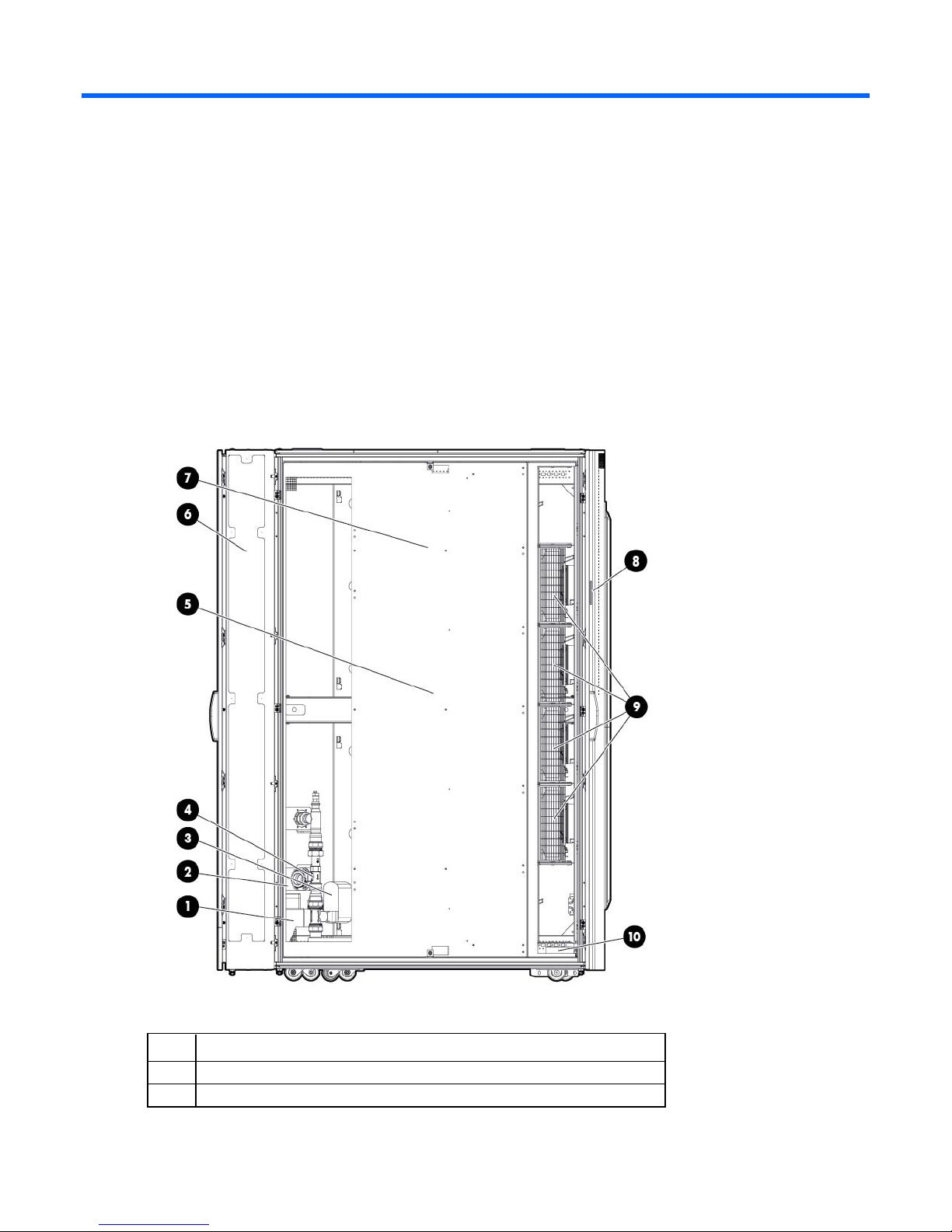
Unit side view
Item Reference
1
2
Condensation pump
Condensation pump controller
Overview 5
Page 6
Item Reference
Management module
3
4
5
6
7
8
9
10
Control valve
Flow meter
Humidity sensor
Rear extension
Heat exchanger unit
TFT touchscreen display
Fan units (4 fans by default, 6 fans maximum)
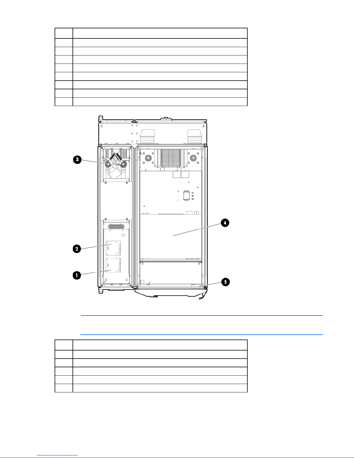
Unit top view
NOTE: For easier viewing, the canopies were removed in the previous illustration.
Item Reference
1
2
3
4
5
Water module
Fan module
Condensation pump transformer 277v (optional)
AC transfer switch
Emergency door opening
Overview 6
Page 7

Configuration factors
Optimum environment and site preparation
CAUTION: Contaminated water might cause decreased cooling capacity or disruption in
service. The water flowing into the MCS-200 unit must meet the guidelines stated in the HP
Modular Cooling System 200/100 Site Preparation Guide. The MCS-200 warranty does not
To provide optimum performance with minimum maintenance, your unit must meet environmental
requirements.
The HP Modular Cooling System 200/100 Site Preparation Guide provides information about planning your
unit configuration efficiently and organizing your site location before delivery of your MCS-200 unit.
To route water lines to your MCS-200 unit, use one of the following methods:
• Through an opening in the raised floor
• Lying on top of the floor
• Through the top of the MCS-200 unit
For more information on routing the water lines, see the Hook Up Kit installation instructions in the HP
Modular Cooling System 200/100 Options Installation Guide.
cover damage caused by contaminated water.
IMPORTANT: Before you begin the installation process, review the HP Modular Cooling System
200/100 Site Preparation Guide.
Safety information
The HP Modular Cooling System is tested to the maximum pressure (PS) of 8 bar (116 PSI) without fluid
trapped inside by closed, external valves.
If valves are installed on the external pipe work that could potentially trap fluid inside the MCS-200 unit,
special precautions must be taken. To prevent severe plumbing failure due to extreme pressure, use an
expansion tank with a preinstalled safety valve in the plumbing circuit connected to the unit.
Configuration factors 7
Page 8

Installation
MCS-200 kit contents
• MCS-200 unit installed on an HP Rack (1)
• Automatic Door Release kit (1)
• Rear plate cover (1)
• Condensation hose (blue) (1)
• Condensation hose (clear)* (1)
• Power cord, 4 m (13.1 ft), L6-20 to Walther Procon series A5 connector (2)
• Power cord, 4 m (13.1 ft), IEC-309 to Walther Procon series A5 connector (2)
• CAT5e cable, 7.62 m (25 ft) (1)
• USB program cable* (1)
• Access panel (1)
• Bracket (2)
• M6 trilobe flathead screw (2)
• M6 flathead screw (2)
*This item might ship preinstalled on the MCS-200 unit rather than in the standard kit contents package.
Installation 8
Page 9
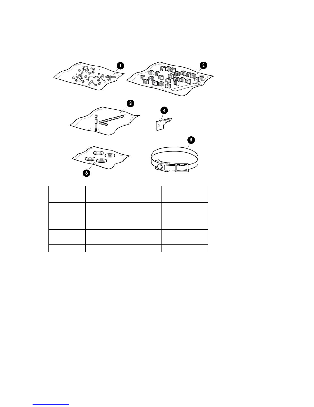
Hardware kit contents
T-25 bit socket
1
If any of the following items are missing or damaged, contact your HP authorized reseller.
Item Description Quantity
1
2
3
4
5
6
Extra hardware might be included for your convenience.
M6 screws 24
M6 cage nuts
Cage nut tool
Allen key
Door/side panel key 2
Quarter turn hook and loop strap 10
Leveling pads 4
Required tools
The following tools are required for installation:
• Flat blade screwdriver
• #2 Phillips screwdriver
• Adjustable wrench
24
1
1
• T-25 Torx screwdriver
• T-30 Torx screwdriver
• Bubble level
• Hose wrenches (2)
Installation 9
Page 10
Installing the MCS-200
WARNING: The MCS-200 unit and rack are shipped together on a heavy duty shock pallet
weighing approximately 1600 kg (3600 lb). HP recommends hiring professional movers to move
the heavy duty shock pallet, remove the MCS-200 unit and rack from the pallet, and move the
1. Install the HP Modular Cooling System Hook Up Kit.
2. Read the unpacking instructions on the MCS-200 packaging material.
3. Using four or more people, remove the MCS-200 unit and rack from the pallet.
4. Roll the MCS-200 unit and rack to the final location.
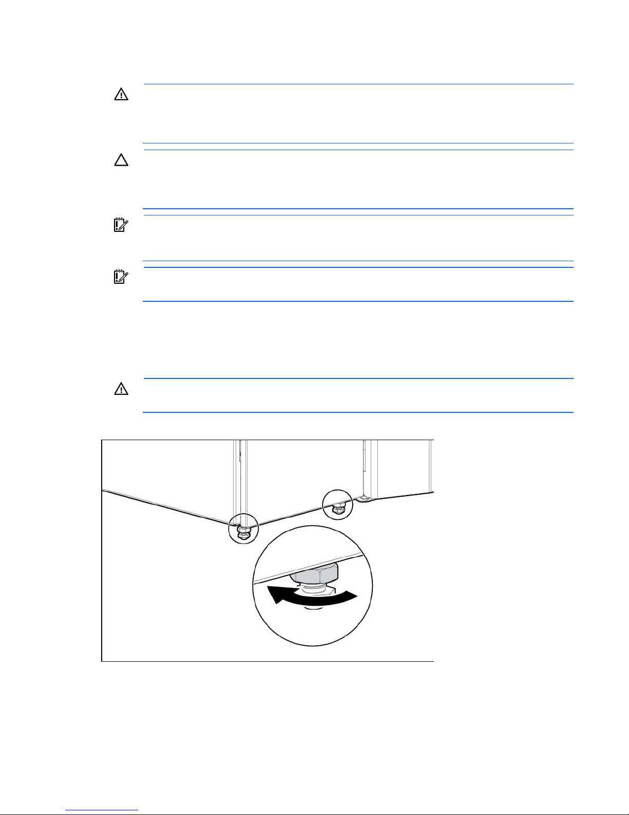
5. To adjust the leveling feet and level the MCS-200 unit, use a bubble level.
MCS-200 unit and rack to the final location.
CAUTION: Contaminated water might cause decreased cooling capacity or disruption in
service. The water flowing into the MCS-200 unit must meet the guidelines stated in the HP
Modular Cooling System 200/100 Site Preparation Guide. The MCS-200 warranty does not
cover damage caused by contaminated water.
IMPORTANT: Because the MCS-200 unit consumes a large quantity of water, do not operate the
MCS-200 unit from a public water system such as one that supplies drinking water. For water
conservation purposes, to cool the MCS-200 unit, use only recycled water systems.
IMPORTANT: Before you begin the installation process, review the HP Modular Cooling System
200/100 Site Preparation Guide.
WARNING: To avoid tipping the MCS-200 unit over, make sure the leveling feet are lowered
when the MCS-200 is equipped, serviced, and operated.
Installation 10
Page 11

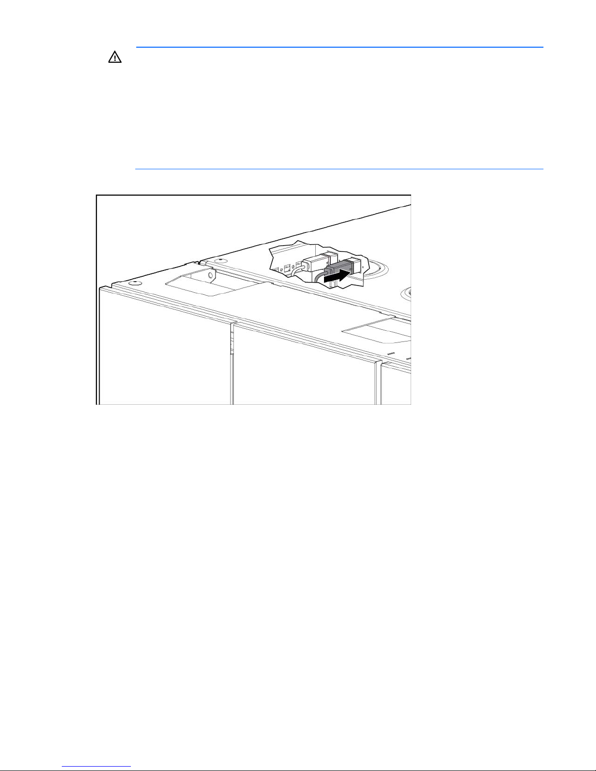
6.
Plug the network cable into the RJ-45 connector on the transfer switch in the top of MCS-200 unit.
7. Plug the other end of the network cable into your network connection outlet.
WARNING: Before you connect the power cords to a power source, be sure that the unit is
properly grounded for potential equalization caused by high leakage current.
IMPORTANT: Do not connect the power cords into a power supply.
8. Plug the primary power cord into the power connector on the left at the power distribution inside the
MCS-200 unit.
Installation 11
Page 12
WARNING: To reduce the risk of electric shock or damage to the equipment:
Plug the power cord into a grounded (earthed) electrical outlet that is easily accessible at all
• Do not disable the power cord grounding plug. The grounding plug is an important safety
feature.
•
times.
• Unplug the power cord from the power supply to disconnect power to the equipment.
• Do not route the power cord where it can be walked on or pinched by items placed against it.
Pay particular attention to the plug, electrical outlet, and the point where the cord extends from
9. If you are using a secondary power cord, plug it into the power connector on the right.
the storage system.
10. Guide the other ends of the power cords through the MCS-200, and then plug them into an appropriate
power source.
11. Install the Automatic Door Release kit hardware. For more information, see the HP Modular Cooling
System 200/100 Rack Options Installation Guide.
Installation 12
Page 13
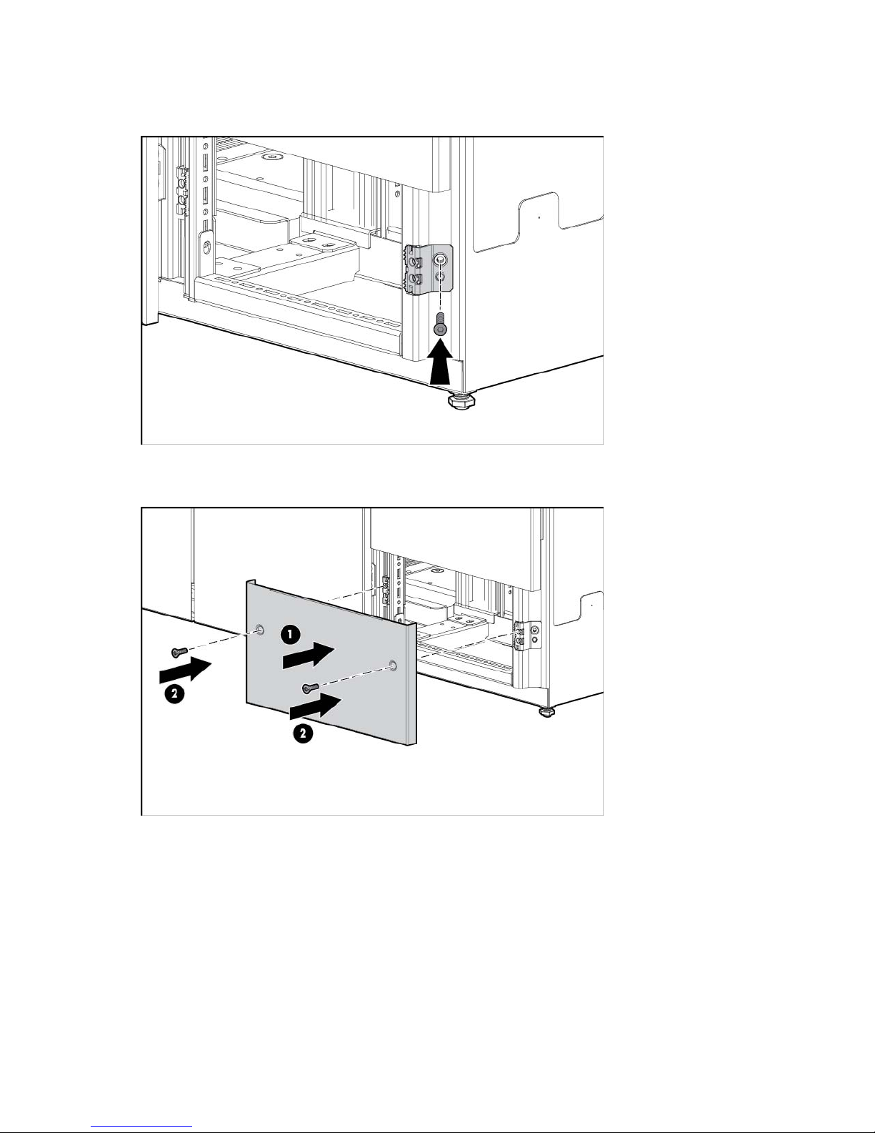
12.
If the rear extension is installed, this step is optional. Using two M6 trilobe flathead screws, secure the
two brackets to the MCS-200 unit frame. For more details on how to install the brackets, see the HP
Modular Cooling System 200/100 Options Installation Guide.
13. Align the access panel with the two brackets.
14. Using two M6 flathead screws, secure the access panel to the brackets on the MCS-200 unit frame.
Powering up and configuring the unit
Installation 13
Page 14

WARNING: To reduce the risk of electric shock or damage to the equipment:
• Do not disable the power cord grounding plug. The grounding plug is an important safety
feature.
• Plug the power cord into a grounded (earthed) electrical outlet that is easily accessible at all
times.
• Unplug the power cord from the power supply to disconnect power to the equipment.
• Do not route the power cord where it can be walked on or pinched by items placed against it.
Pay particular attention to the plug, electrical outlet, and the point where the cord extends from
1. Plug the power cord into an appropriate power source in accordance with your local electrical
the storage system.
connection standards.
2. Connect the network cable to your network infrastructure.
NOTE: If you have a DHCP server, you can change the IP address through the web interface
instead of through the virtual serial port. For more information, see "Configuring the IP address
3. If you are connecting through the virtual serial port with the provided USB cable, then you must
through the web interface."
download and install the USB driver, available from the HP website (http://www.hp.com).
4. Using the USB cable provided, connect a PC to the USB port on the management module.
5. If your Windows operating system does not prompt you to install a driver, you must install it manually
through the device manager and locate the downloaded driver.
6. Access the management module through a terminal emulation program, such as Minicom or
HyperTerminal ("Configuring HyperTerminal" on page 43).
7. Confirm that you have set the following parameters to access a terminal emulation program:
o Bits per second: 9600
o Data bits: 8
o Parity: none
o Stop bits: 1
o Flow control: none
8. Log in to the HP Modular Cooling System Configuration Utility:
a. In the login field, enter the user name. The default user name is Admin.
Installation 14
Page 15
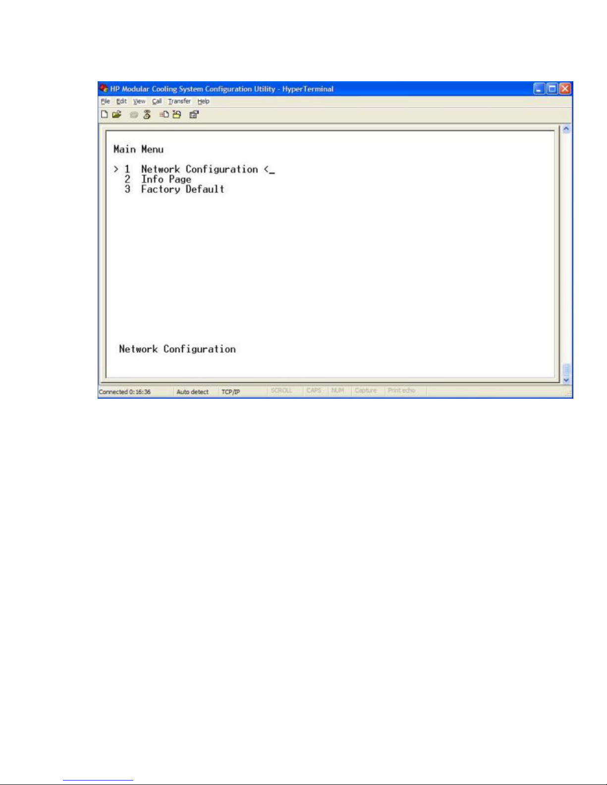
b.
In the password field, enter the password. The default password is Admin. The Main Menu screen
appears.
9. Enter the product ID and serial number on the 1 Network Configuration line. The product ID and
10-digit serial number are located on a label inside the rear MCS-200 unit door.
Installation 15
Page 16
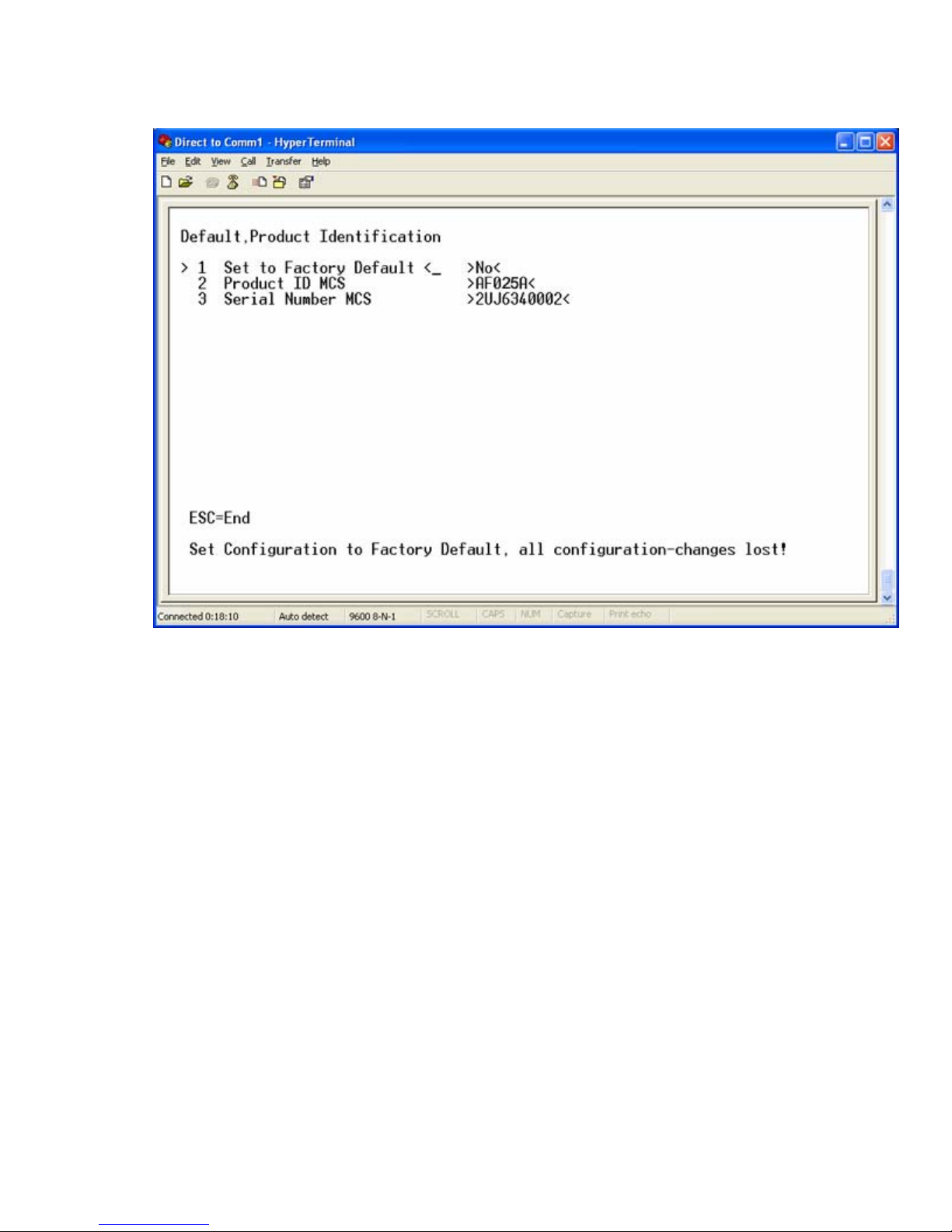
From the Main Menu screen, select 3 Factory Default. and press Enter. The Default Product
a.
Identification screen appears.
b. To set the product ID, select 2 Product ID MCS and press Enter.
c. To set the serial number, select 3 Serial Number MCS and press Enter.
d. To return to the Main Menu screen, press Esc.
10. Change the DHCP configuration, and then enter the IP address, IP subnet mask, and gateway:
Installation 16
Page 17

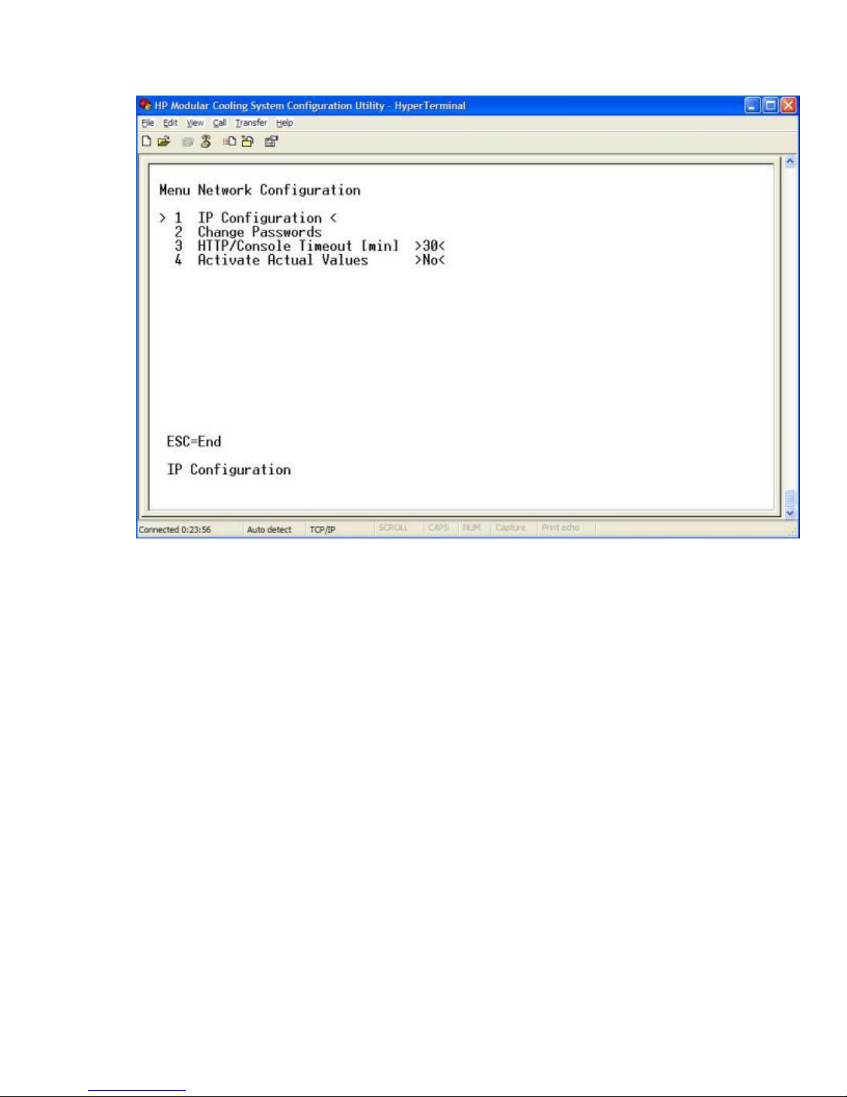
From the Main Menu screen, select 1 Network Configuration and press Enter. The Menu
a.
Network Configuration screen appears.
Installation 17
Page 18
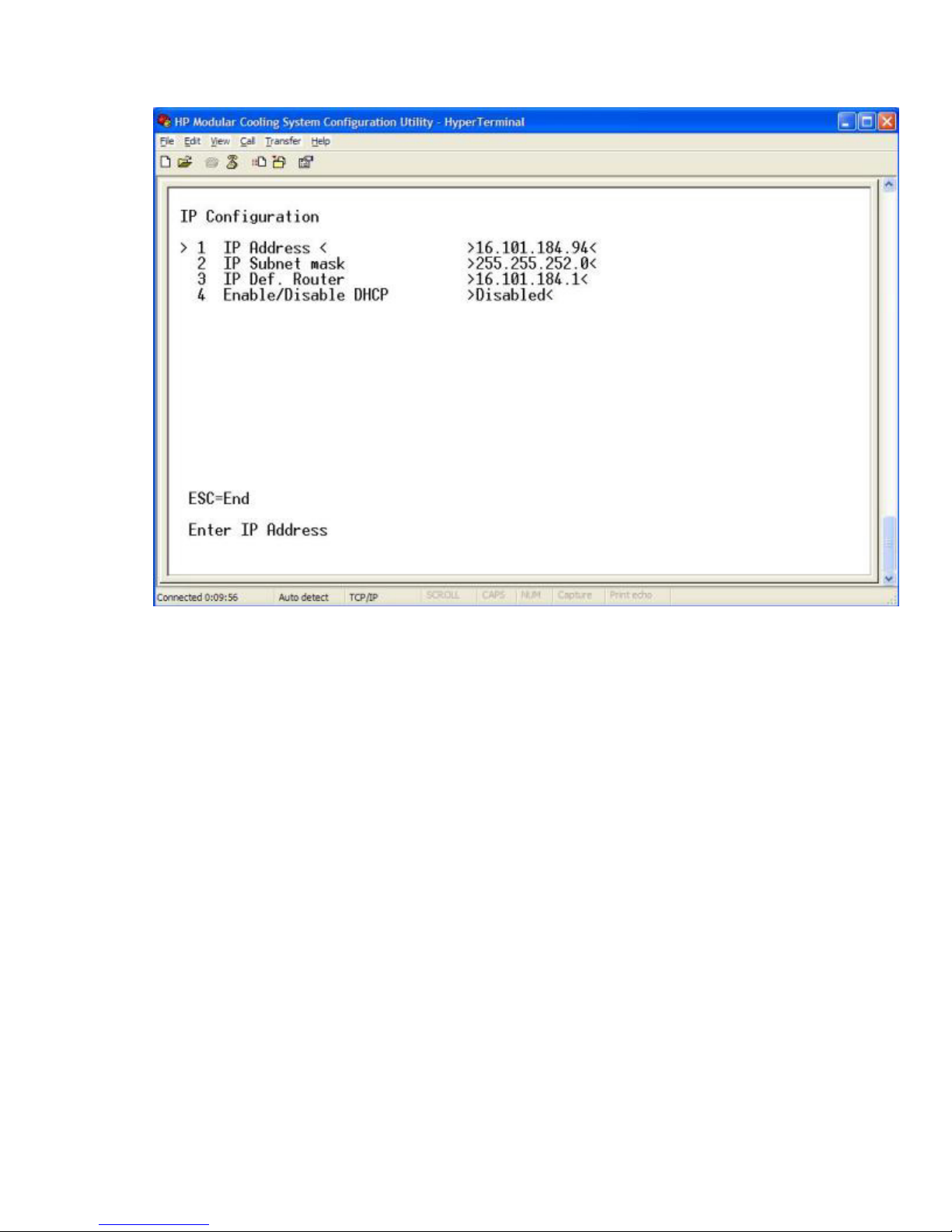
Select 1 IP Configuration and press Enter. The IP Configuration screen appears.
b.
c. To disable DHCP, select 4 Enable/Disable DHCP and press Enter.
d. Select 1 IP Address, and then enter the new IP address.
e. Select 2 IP Subnet mask, and then enter the IP subnet mask.
f. Select 3 IP Def. Router, and then enter the gateway.
11. Activate the values:
Installation 18
Page 19
a.
Return to the Main Menu Network Configuration screen.
b. Select 4 Activate Actual Values and press Enter.
c. To reboot, at the prompt, enter y. You must reboot to activate the IP settings, product ID, and serial
number values.
12. Access the Management module through the web interface:
a. Launch a supported browser. The browser window appears.
b. In the Address field (Microsoft® Internet Explorer) or the Location field (Firefox Mozilla), enter
http://ipaddress (where ipaddress is the IP address of the management module).
The login screen appears.
13. Log in through the web interface:
a. Enter the user name in the User Name field. The default user name is Admin.
b. Enter the password in the Password field. The default password is Admin.
Installation 19
Page 20
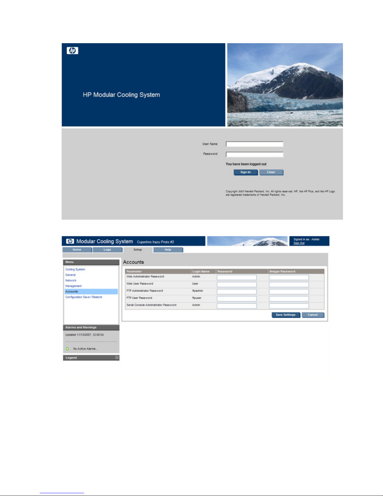
c.
Click Sign In.
14. Click Setup>Accounts, and then change the default Web Admin and Web User passwords.
15. Click Save Settings.
16. Optional, but HP-recommended: Click Setup>Management>Remote Access, and then select SSL
Enable.
Installation 20
Page 21
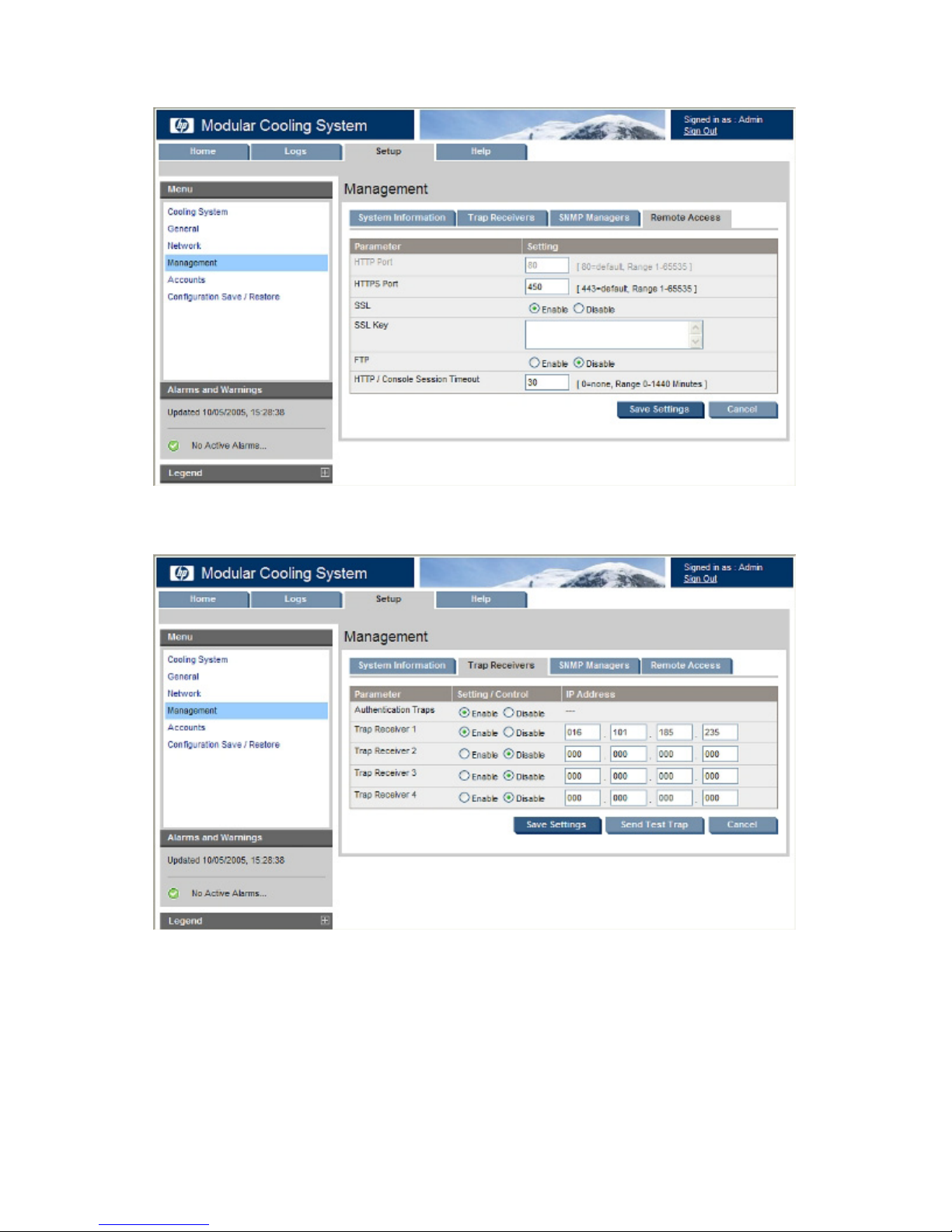
17.
Optional: Enter an SSL key.
18. Click Save Settings.
19. To set up your trap receivers, click Setup>Management>Trap Receivers.
20. Click Save Settings.
Installation 21
Page 22
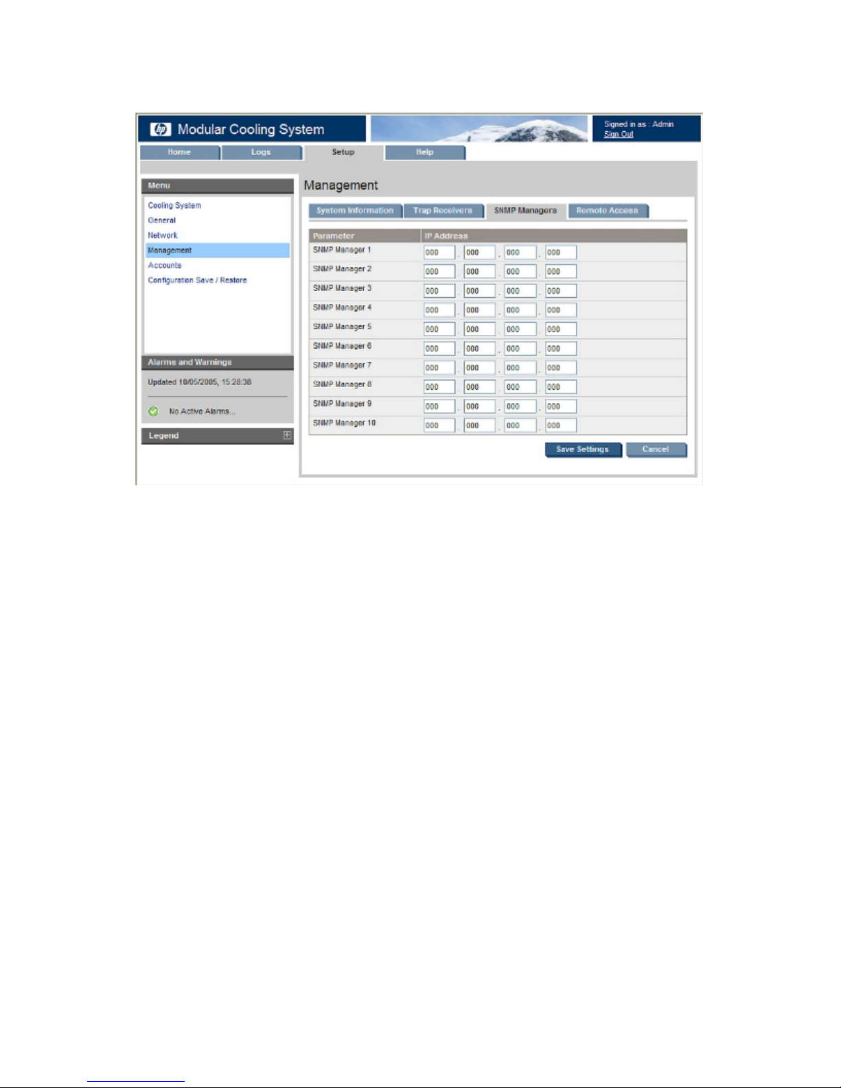
21.
Optional, but HP-recommended: To set up your SNMP managers, click Setup>Management>SNMP
Managers.
22. Click Save Settings.
Configuring the IP address through the web interface
1. View the IP address received from DHCP on the operator display.
2. Access the Management module through the web interface:
a. Launch a supported browser. The browser window appears.
b. In the Address field (Microsoft® Internet Explorer) or the Location field (Mozilla Firefox), enter
http://ipaddress (where ipaddress is the IP address of the management module).
The login screen appears.
3. Log in through the web interface:
a. Enter the user name in the User Name field. The default user name is Admin.
b. Enter the password in the Password field. The default password is Admin.
Installation 22
Page 23
c.
Click Sign In.
4. Click Setup>Network.
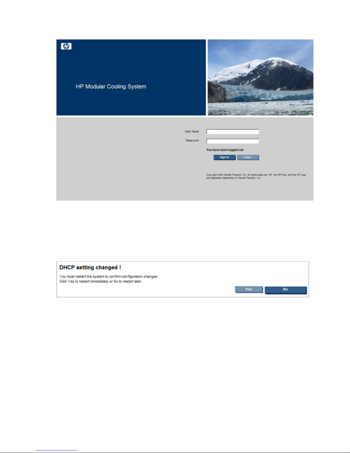
a. To disable DHCP, click the radio button. The default setting is enabled. Whenever you make a
change regarding DHCP, you must restart the server. A new screen will appear prompting you to
restart.
— To restart the server immediately, select Yes.
— To return to the Network screen, select No.
b. Click Save Settings.
c. In the IP Address field of the management module, change the IP address.
d. Change the network mask of the management module.
e. Change the default gateway of the management module.
f. Click Save Settings. A new screen appears, indicating that the server must be restarted for the
changes to take effect. If any new settings are saved, the server restarts automatically.
Installation 23
Page 24

g.
Log in to the new IP address.
5. Click Setup>Accounts, and then change the default Web Admin and Web User passwords.
6. Click Save Settings.
7. (Optional, but HP-recommended) Click Setup>Management>Remote Access, select SSL Enable.
8. (Optional) Enter an SSL key.
9. Click Save Settings.
Installation 24
Page 25

10.
To set up your trap receivers, click Setup>Management>Trap Receivers.
11. Click Save Settings.
12. (Optional, but HP-recommended) To set up your SNMP managers, click Setup>Management>SNMP
Managers.
13. Click Save Settings.
For more information on adjusting the management module settings through the web interface, see the HP
Modular Cooling System 200/100 Web Interface User Guide.
Connecting water to the facility
CAUTION: Before attaching the hoses to the MCS-200 unit, verify that the water supply and
return are closed. Water that leaks into the unit can cause significant damage.
CAUTION: Do not over tighten the connection. Tightening the connection too much might
damage the gaskets.
NOTE: The MCS-200 unit is equipped with a failed-open control valve. For water to flow through
the unit without restrictions during the initial water hook up, HP recommends that the control valve
is set manually to Open through the web interface.
Installation 25
Page 26

1.
Route the water hoses from the HP Modular Cooling System Hook Up Kit through the floor cut-out, and
then use a hose wrench to install each main hose to the MCS-200 unit. For information on floor cut out
dimensions, see the HP Modular Cooling System 200/100 Site Preparation Guide.
2. Route the two drain hoses to the drain collection system catch basin:
a. Install and route the blue drain hose into either the water return line or the gravity drain collection
system catch basin.
b. Route the preinstalled clear drain hose into the gravity drain collection system catch basin.
c. Position the gravity drain collection system below the water collection pan, enabling gravity to draw
the water out of the water collection pan and into the gravity drain collection system basin.
3. Log in to the web interface:
a. Enter the user name in the User Name field. The default user name is Admin.
Installation 26
Page 27

b.
Enter the password in the Password field. The default password is Admin.
c. Click Sign In.
4. Click Setup>Advanced.
5. In the Temperature Control field, select Manual, and then click Save Settings.
You can now set the Fan Speed Target and Water Valve fields manually.
6. In the Water Valve field, to open the valve completely, enter 100, and then click Save Settings.
Installation 27
Page 28

7.
Turn on the water by opening the ball valves at the facility water line connections.
8. In the web interface, click the Home tab.
9. To verify that the water source is available and turned on, select the Overview menu, and then verify the
Water Flow status.
Installation 28
Page 29

10.
If necessary, remove trapped air from the heat exchanger by opening the bleeder valve on the top rear
side of the cooling unit. To verify that the heat exchanger is bleeding correctly, verify that a few drops
of condensation pass through the clear tube.
11. After you have verified the flow and removed the air, in the web interface, click Setup>Advanced.
12. In the Temperature Control field, select Automatic, and then click Save Settings.
The installation is complete.
Installation 29
Page 30

Automatic Door Release Kit
Automatic Door Release Kit Overview
The Automatic Door Release Kit is designed as a safety mechanism in the event that the MCS-200 unit shuts
off unexpectedly. If the MCS-200 unit shuts off unexpectedly, the electromagnetic locks on the front door, the
rear master door, and the rear slave door are immediately deactivated. This deactivation of the
electromagnetic locks will cause the release springs on each door to spring the rack doors open and allow
air flow and cooling to the servers in the rack.
The Automatic Door Release Kit is included with your MCS-200 unit. For specific installation instructions, see
Automatic Door Release Kit
the HP Modular Cooling System Automatic Door Release Kit Installation Instructions included with the kit.
To view the HP Automatic Door Release hardware installation instructions, see the HP Modular Cooling
System Rack Options Installation Guide.
To enable the automatic door release:
1. Click Setup>Advanced.
2. In the Emergency Door Opening field, select Enable.
When the function has been enabled, an indicator appears on the Home tab showing the current status of the
rack doors. Also, a new button appears on the Advanced tab, enabling you to test the feature.
Automatic Door Release Kit 30
Page 31

To test the Automatic Door Release feature:
1. At the bottom of the screen, click the Door Opening Test button. A new screen appears.
2. Choose one of the following:
o To begin the test and open the rack doors, click OK.
o To return to the Advanced screen, click Quit.
NOTE: To avoid an increase in relative humidity, after completing the Door Opening test, be
sure the doors are closed. To verify that the doors are closed, go to the Home screen.
NOTE: You can also perform this test from the Operator Display.
Automatic Door Release Kit 31
Page 32

Management module
Management module overview
The HP Modular Cooling System has a management module, which can be accessed remotely through the
web interface. The management module analyzes, queries, and manages various measurements and
warning and alarm messages from the unit.
The management module (on page 32) analyzes measurements provided by each sensor or module,
generates any necessary warning or alarm messages, and then sends them to the web interface. When a
new warning or alarm occurs, the warning and alarm messages (on page 45) appear on the operator
display as well as on the web interface Alarms menu and Alarm History menu. An alarm relay is also
activated (if installed on the unit and enabled in the appropriate web interface menu), and an audible alarm
is signaled by the internal beeper (if enabled in the appropriate web interface menu).
The management module performs regulation operations such as:
• Retrieving all measurements from the fan units and the water units in cycles, approximately once per
second (temperature, fan speed, and chilled water flow rate)
• Analyzing all measurements and generated alarm and warning messages
• Calculating heat removed from the water flow rate and temperature of the water supply and return
• Measuring water flow rate
• Regulating the server air inlet temperature by controlling the water flow
• Sending control settings for fan speeds back to the MCS-200 unit
• Sending various system values to the web interface
The web interface displays various measurements and warning and alarm messages (on page 45) from the
management module. Also, various system values can be set through the web interface and sent to the
management module. For more information about the web interface, see the HP Modular Cooling System
Web Interface User Guide.
The following values can be set through the web interface and sent to the management module:
• Server Intake Temperature Set Point—Target value used by the management module for server intake
regulation
• High Temperature Threshold—Temperature difference above Server Intake Temperature Set Point for
temperature-critical alarm message
• Warning Temperature Threshold—Temperature difference above Server Intake Temperature Set Point
for temperature warning message
• Low Temperature Threshold—Temperature difference below Server Intake Temperature Set Point for
temperature warning message
The following values are displayed in the web interface for information only:
• Fan Speed—Displays the fan speed percentage
• Water Valve—Displays the water valve state
Management module 32
Page 33

• Fan Module—Displays the Server Intake and Server Exhaust Temperature as well as the RPM of each
•
•
•
•
•
•
fan
• Water Inlet Temperature—Displays the temperature of the water coming into the MCS-200 unit to be
used to cool the servers
• Water Outlet Temperature—Displays the temperature of the water after removing the server heat
• Water Flow—Displays the value of the water flow in liters/gallons per minute
Management module components
The management module is located on the lower front of the MCS-200 unit, behind the front door.
Item Reference Description
C key Used to confirm warnings, critical alarms, and
1
Power/alarm LED Used to indicate the internal status of the management
2
configuration setting changes, as well as to turn off the
audible alarm. To confirm these situations, press and
hold the C key for five seconds, or click the Clear Alarms
button on the Setup tab>General menu on the web
interface.
module, and to signal warnings and critical alarms.
If the LED is green, the management module has
power, and conditions are normal.
If the LED is green and blinking, communication is
taking place.
If the LED is yellow, a warning has been issued.
If the LED is red, a critical alarm has been issued.
If the LED is blinking green, yellow and red, then a
configuration setting change has been made. To save
the new configuration settings to the internal memory
Mini USB
3
connection
of the management module, press and hold the C key
for five seconds.
If the LED is off, the management module has no
power.
Used for USB connections for initial setup.
Management module 33
Page 34

Accessing the management module through a
terminal emulation program
1. Verify that a serial cable is connected between the management module and a host computer.
2. Launch a terminal emulation program such as HyperTerminal ("Configuring HyperTerminal" on page
43) or Minicom.
For information about configuring the management module, see the HP Modular Cooling System Web
Interface User Guide.
3. Log in through the terminal emulation program ("Logging in through the terminal emulation program"
Logging in through the terminal emulation program
on page 34).
1. Enter the user name in the login field. The default user name is Admin.
2. Enter the password in the password field. The default password is Admin. The Main Menu screen
appears.
Accessing the management module through the web
interface
1. Launch a supported browser. The browser window appears.
Management module 34
Page 35

2.
•
•
•
•
In the Address field (Microsoft® Internet Explorer) or the Location field (Mozilla), enter one of the
following:
http://hostname[:port number]
-orhttps://hostname[:port number] (if SSL is enabled)
where hostname is the IP address of the management module and port number is the port number if
using a port other than the default 80 for http and 443 for https. The login screen appears.
3. Log in through the web browser ("Logging in through the web interface" on page 35).
Web interface requirements
The following table lists the minimum requirements necessary to operate the web interface.
Component Requirement
Web browser on a client
Monitor resolution
Desktop resolution
Microsoft® Internet Explorer 8.0
Red Hat Linux operating system (32-bit only)
SUSE Linux operating system (32-bit only)
Mozilla Firefox 4.0
Minimum supported resolution of 1024 x 768, 16-bit
high color. (Maximize the browser window for optimal
display.)
SLES 11 Mozilla Firefox 3.6.17
To configure the desktop resolution:
1 Right-click the mouse, and select Configure
Desktop.
2 Select 1152 x 864.
3 Select 75 Hz.
Logging in through the web interface
1. Enter the user name in the User Name field. The default user name is Admin.
NOTE: Passwords are case-sensitive.
2. Enter the password in the Password field. The default password is Admin.
3. Choose one of the following options:
o Click Sign In. The HP Modular Cooling System web interface appears.
o To clear the credentials, click Clear.
Management module 35
Page 36

For instructions on changing the password, see the HP Modular Cooling System Web Interface User
Guide.
Only one Admin session and one User session are supported at a time. If a second session is initiated (after
successful login) or a console session timeout occurs, sessions can be terminated. In both situations, the
existing session is terminated and the login screen appears. Admin session logins, logouts, and terminations
are recorded in the Event Log menu. The console session timeout length can be enabled, disabled, or
modified in the Remote Access tab. The default is 30 minutes.
Management module 36
Page 37

Connecting an alarm device to the management
The connection to the alarm relays is hard wired. For more information, see connection
module alarm relay
An alarm device can be connected to the management module alarm relay through the RJ-12 connector. You
can enable or disable the alarm relay for specific alarms and warnings through the web interface. 24 V DC
up to 100 mA is available directly from the management module or the alarm relay can switch up to 30 V at
1 A. For more information, see the HP Modular Cooling System 200/100 Web Interface User Guide.
NOTE:
description on the management module.
Alarm relay item Specification
Type of alarm relay
Maximum current
consumption
Maximum voltage
Potential-free change-over contact
100 mA with internal
or
1 A with external power connection
DC, 24 V internal
or
DC, 30 V with external power connection
Management module 37
Page 38

Serial interface
HP Modular Cooling System Utility overview
The HP Modular Cooling System Configuration Utility is used for entering network settings, accessing
controls, reviewing the details on the info page, and resetting to factory defaults.
First, log in to a terminal emulation program. ("Logging in through the terminal emulation program" on page
34) After you have successfully initiated a terminal emulation session, the HP Modular Cooling System
Configuration Utility appears.
• Open a submenu by entering the corresponding option number at the prompt.
• Enter or change configuration information by following the onscreen prompts.
• Press Esc or enter 0 at the submenu prompt to go to the previous menu.
-orPress Esc or enter 0 at the main menu prompt to exit the utility.
• The management module must be reset before configuration changes can take effect.
Main menu
Serial interface 38
Page 39

Option number Submenu Description
1
2
3
Network Configuration Enter or change network properties for the
Info Page View parameters for the management module.
Factory Default Change parameters back to default settings.
Menu Network Configuration submenu
management module.
Option number Submenu Description
1
2
3
4
IP Configuration Enter or change the IP configuration for the
management module.
Change Passwords Enter or change the passwords for the
management module.
HTTP/Console Timeout [min] Enter or change the minimum HTTP/console
timeout for the management module.
Activate Actual Values Select to accept changes and restart the unit.
Serial interface 39
Page 40

IP Configuration submenu
Option number Submenu Description
1
2
3
4
IP Address Enter or change the IP address for the
management module.
IP Subnet mask Enter or change the subnet mask for the
management module.
IP Def. Router Enter or change the default router for the
management module.
Enable/Disable DHCP Select to enable or disable DHCP.
Serial interface 40
Page 41

Change Passwords submenu
Option number Submenu Description
1
2
3
4
5
Console Password 'Admin' Change the Admin password.
FTP Password 'ftpuser' Change the FTP user password.
FTP Password 'ftpadmin' Change the FTP Admin password.
HTTP Password 'User' Change the HTTP user password.
HTTP Password 'Admin' Change the HTTP Admin password.
Serial interface 41
Page 42

Info page
The Info page displays the following parameters:
• IP Address
• Subnetmask
• Router/Gateway
• MAC Address
• SysName
• SysContact
• SysLocation
• Software Version
• Hardware Version
• Firmware
• Serial Number
• Manufacture Date
• CMC-Info
Serial interface 42
Page 43

Factory Default submenu
Option number Submenu Description
1
2
3
Set to Factory Default Set the management module to factory default.
Product ID MCS Set the MCS unit product ID.
Serial Number MCS Set the MCS unit serial number.
Configuring HyperTerminal
1. From the Microsoft® Windows® desktop menu, click Start>All
Programs>Accessories>Communication>HyperTerminal. The Connection Description window
appears.
2. Enter a description and select an icon for the connection. The Connect To window appears.
3. Select the Com port through which to connect. The Com Properties window appears.
4. Select the following parameter values.
Parameter Value
Transmission rate
Data bits
Parity
Stop bits
Flow control
9600 Bps
8
None
1
None
Serial interface 43
Page 44

Minicom is a utility that is loaded during the installation of Linux. However, if you
5.
When a connection is established, press Enter and then log in. The Main menu for the management
module appears. Follow the onscreen options to configure the management module.
Configuring Minicom
NOTE: The following example uses Red Hat Linux 3.0. For more information, refer to your Linux
1. Log in to a Linux console, or open a terminal and enter minicom-s at the command prompt. The
2. Select Serial Port Setup. The Change which setting? menu appears.
3. Select Option A (Serial Device). Manually change the device type from "dev/modem" to "/dev/ttyS0"
4. Select Option E (Bps/Par/Bits). The Comm Parameters menu appears.
5. Select E (Speed 9600 Bps), and press Enter. The designation 9600 8 N1 appears next to Option E.
6. Select Option F (Hardware Flow Control).
7. Be sure that the Change which setting? menu is configured as follows:
operating system Help or documentation.
IMPORTANT:
do not select the option to install the Linux Utilities during the operating system installation, you
cannot use Minicom without downloading the Minicom X.X.i386.rpm file from the Red Hat
website. (Refer to the procedure for installing RPMs on the Red Hat website.)
Configuration menu appears.
and press Enter.
o A—Serial Device: /dev/ttyS0
o B—Lockfile Location: /var/lock
o C—Callin Program:
o D—Callout Program:
o E—Bps/Par/Bits: 9600 8 N1
o F—Hardware Flow Control: No
o G—Software Flow Control: No
8. Press Enter to return to the Configuration menu. Scroll down to the Save setup as default option, and
press Enter. Scroll down the Configuration menu to the Exit from the Minicom option, and press Enter.
9. From the command prompt, enter Minicom. As soon as a connection is established, press Enter and
log in. The Main menu for the management module appears. Follow the onscreen options to configure
the management module.
Serial interface 44
Page 45

Operator display
Operator display overview
The operator display provides information on the system operation, viewable on the outside of the MCS-200
front door. When the management module issues an alarm or warning, the warning and alarm messages
display ("Warning and alarm messages" on page 45) on the operator display, as well as on the web
Operator display components
interface Alarms menu and Alarm History menu.
The operator display on the front door of the MCS-200 unit has a digital touch-screen.
To scroll through the menu options, press the appropriate button on the bottom of the screen.
Warning and alarm messages
The following tables describe the possible warning and alarm messages that the MCS-200 unit sends to the
management module. These messages appear on the operator display and on the web interface Alarms
menu and Alarm History menu.
Fan unit failed or not installed
Indicators Meaning
Operator display alarm message
Web interface alarm message
Condition
Sensors
SNMP notification
Fan 1, 2, 3, 4, 5, or 6 Failed
Fan 1, 2, 3, 4, 5, or 6 Failed or Not Installed
Fan 1, 2, 3, 4, 5, or 6 is running at less than the minimum RPM
Fan 1, 2, 3, 4, 5, or 6
Warning
Operator display 45
Page 46

Indicators Meaning
Water flow Low
Type of message
Warning
Solution:
1. Remove the fan unit.
2. Reinstall the same fan unit.
If the warning message does not clear after the module is reseated, replace the fan unit with a CSR part. For
more information on CSR parts, see "Replaceable parts and maintenance and service information (on page
59)."
HEX (heat exchanger unit) temperature in failed (Server Intake Temperature failed)
Indicators Meaning
Operator display alarm message
Web interface alarm message
Condition
Sensors
SNMP notification
Type of message
HEX1, HEX2, or HEX3 Temp. In Failed
Top Heat Exchanger Intake Air Temperature Sensor to Server Failed
Temperature reading is beyond limit (possible open circuit)
HEX1, HEX2, or HEX3 sensors (This value is the water to air heat exchanger
unit temperature of the intake to the servers.)
Warning
Warning
Solution:
Contact HP, or see the HP website (http://www.hp.com).
HEX temperature out failed (Server Exhaust Temperature failed)
Indicators Meaning
Operator display alarm message
Web interface alarm message
Condition
Sensors
SNMP notification
Type of message
HEX1, HEX2, or HEX3 Temp. Out Failed
Top Heat Exchanger Exhaust Air Temperature Sensor from Server Failed
The temperature reading is beyond limit (possible open circuit)
Fan 1, 2, 3, 4, 5 or 6 sensors (This value is the fan unit temperature of the
exhaust from the servers.)
Warning
Warning
Solution:
Contact HP, or see the HP website (http://www.hp.com).
Low water flow
Indicators Meaning
Operator display alarm message
Web interface alarm message
Condition
Modules
SNMP notification
Type of message
Water flow Low
No or low water flow
Water group
Warning
Warning
Operator display 46
Page 47

Solution:
Warning
Verify the water supply.
Water temperature input is out of range
Indicators Meaning
Operator display alarm message
Web interface alarm message
Condition
Sensors
SNMP notification
Type of message
Water Temp. In Failed
Water Unit Temperature Input Out of Range
Water temperature sensor is not working properly (possible open circuit).
Water group sensor
Warning
Warning
Solution:
1. Verify the water supply.
2. Verify whether the water temperature is below or above the water temperature expected range.
3. Contact your building supervisor.
4. Contact HP, or see the HP website (http://www.hp.com).
Water temperature output is out of range
Indicators Meaning
Operator display alarm message
Web interface alarm message
Condition
Sensors
SNMP notification
Type of message
Water Temp. Out Failed
Water Unit Temperature Output Out of Range
Water temperature sensor is not working properly (possible open circuit).
Water group sensor
Warning
Solution:
1. Verify the water supply.
2. Verify whether the water temperature is below or above the water temperature expected range.
3. Contact your building supervisor.
4. Contact HP, or see the HP website (http://www.hp.com).
Water flow sensor is not working properly
Indicators Meaning
Operator display alarm message
Web interface alarm message
Condition
Sensor
SNMP notification
Type of message
Water flow Sensor?
Water flow Sensor Value Out of Range
Water flow sensor is not working properly.
Water group
Warning
Warning
Solution:
Operator display 47
Page 48

1.
Verify the water supply.
2. Contact HP, or see the HP website (http://www.hp.com).
Water flow valve is closed
Indicators Meaning
Operator display alarm message
Web interface alarm message
Condition
Modules
SNMP notification
Type of message
Water Valve?
Water Valve Failed
Water flow valve is closed, and water flow is detected.
Water group
Warning
Warning
Solution:
1. Verify the water valve is closed.
2. Contact HP, or see the HP website (http://www.hp.com).
Leak detector sensor is not working properly
Indicators Meaning
Operator display alarm message
Web interface alarm message
Condition
Sensors
SNMP notification
Type of message
Leak detector?
Leak detector Failed
Leak detector sensor is not working properly.
Leak detector sensor
Warning
Warning
Solution:
Contact HP, or see the HP website (http://www.hp.com).
Uneven heat load
Indicators Meaning
Operator display alarm message
Web interface alarm message
Condition
Sensors
SNMP notification
Type of message
Heat Load?
Heat Load Warning
Measured air temperature values are dramatically different from top to
bottom.
Air temperature sensors
Warning
Warning
Solution:
1. Verify that nothing is blocking the heat path.
2. Verify that the server is loading.
3. Adjust the Temperature Difference for Heat Load Warning in the Advanced tab.
Heat overload condition (High Temperature Threshold field)
Operator display 48
Page 49

Temperature too high
Indicators Meaning
Operator display alarm message
Web interface alarm message
Condition
Modules or sensors
Temperature too high
Heat overload condition
The average server air temperature is above the temperature assigned in the
web interface Intake Temp tab High Temperature Threshold field.
SNMP notification
Type of message
Critical
Alarm
Solution:
1. Verify the water inlet temperature.
2. Verify that the flow matches the specifications required for heat load.
3. Adjust the temperature assigned in the web interface Intake Temp tab High Temperature Threshold field.
Leakage detected
Indicators Meaning
Operator display alarm message
Web interface alarm message
Condition
Modules or sensors
SNMP notification
Type of message
Leakage Detected
Leakage Detected
Leak is detected
Leakage detector actuated
Critical
Alarm
Solution:
1. Open the rack doors.
2. Power down the rack-mounted components.
3. Turn off the water to the MCS-200 unit.
4. Locate and correct the leak.
Communication failure
Indicators Meaning
Operator display alarm message
Web interface alarm message
Condition
Modules or sensors
SNMP notification
Type of message
Comm. Failure I²C
Comm. Failure I²C
The management module cannot communicate with the MCS-200 unit
sensors.
Any module or sensor
Critical
Alarm
Solution:
Power cycle the management module. If the alarm message continues to appear, replace the management
module with a CSR part. For more information on CSR parts, see "Replaceable parts and maintenance and
service information (on page 59)."
Operator display 49
Page 50

Temperature below threshold (Low Temperature Threshold field)
The water flow loss emergency door opening temperature threshold has
Indicators Meaning
Operator display alarm message
Web interface alarm message
Condition
Temperature too low
Temperature too low
The average server air temperature is lower than the temperature assigned
in the web interface Intake Temp tab Low Temperature Threshold field.
Sensors
SNMP notification
Type of message
Air temperature sensor
Warning
Warning
Solution:
1. Verify water flow matches specifications required for heat load.
2. Verify whether the water temperature is below the expected range.
3. Adjust the temperature assigned in the web interface Intake Temp tab Low Temperature Threshold field.
4. Contact your building supervisor.
Temperature above threshold (Warning Temperature Threshold field)
Indicators Meaning
Operator display alarm message
Web interface alarm message
Condition
Modules or sensors
SNMP notification
Type of message
Temperature Warning
Temperature Warning
Average server air temperature is above the temperature assigned in the
web interface Intake Temp tab Warning Temperature Threshold field
Air temperature sensor
Warning
Warning
Solution:
1. Verify water flow matches specifications required for heat load.
2. Verify whether the water temperature is above the expected range.
3. Adjust the temperature assigned in the web interface Intake Temp tab Warning Temperature Threshold
field.
4. Contact your building supervisor.
Emergency Door Opening due to Water Flow Loss (0 l/min; 36/34/35°C) (0 gal/min; 97/93/95°F)
Indicators Meaning
Operator display alarm message
Web interface alarm message
Condition
Modules or sensors
Emergency Door, Flow
Emergency Door Opening due to Water Flow Loss (0 l/min; 36/34/35°C)
(0 gal/min; 97/93/95°F)
The interface alarm message displays the temperatures of the fans so that
you can see which temperature has been exceeded and caused the alarm.
been exceeded or the water flow is less than 2 l/min (.5283 gal/min).
Server Intake Temperature, Water Flow Meter
Operator display 50
Page 51

Indicators Meaning
SNMP notification
Type of message
Critical
Alarm
Solution:
1. Verify the water supply and that the MCS-200 unit is receiving water.
2. Verify that the water pressure delta is accurate.
3. Verify that the water flow loss emergency door opening temperature threshold is not less than 5°C
(41°F) above or more than 20°C (68°F) above the Server Intake Temperature Set Point.
4. Adjust the temperature in the Server Intake Temperature Set Point or the Water Flow Loss Emergency
Door Opening Temperature Threshold fields to prevent false alarms.
IMPORTANT: Use caution when entering temperatures in the Emergency Door Opening fields.
Setting the temperature thresholds too low might cause the MCS unit to shut down.
Emergency Door Opening due to High Temperature (35/36/38°C) (95/97/100°F)
Indicators Meaning
Operator display alarm message
Web interface alarm message
Condition
Modules or sensors
SNMP notification
Type of message
Emergency Door, Heat
Emergency Door Opening due to High Temperature (35/36/38°C)
(95/97/100°F)
The interface alarm message displays the temperatures of the fans so that
you can see which temperature has been exceeded and had caused the
alarm.
The High Temperature Emergency Door Opening Threshold has been
exceeded.
Server Intake Temperature
Critical
Alarm
Solution:
1. Verify the water supply and that the MCS-200 unit is receiving water.
2. Verify that the High Temperature Emergency Door Opening Threshold is not less than 5°C (41°F) above
or more than 20°C (68°F) above the Server Intake Temperature Set Point, or that it is not below the
Water Flow Loss Emergency Door Opening Temperature Threshold.
3. Adjust the temperature in the Server Intake Temperature Set Point or the Water Flow Loss Emergency
Door Opening Temperature Threshold fields to prevent false alarms.
IMPORTANT: Use caution when entering temperatures in the Emergency Door Opening fields.
Setting the temperature thresholds too low might cause the MCS unit to shut down.
The condensation pump has exceeded x cycles
Indicators Meaning
Operator display alarm message
Web interface alarm message
Excessive moisture
The condensation pump has exceeded x cycles
Operator display 51
Page 52

Indicators Meaning
hour window. The clock stops and the counters are reset to zero for warning purposes if the
Condition
The water level has exceeded the permissible level of the condensation
pump sensor.
Modules or sensors
SNMP notification
Type of message
Condensation pump sensor
Warning
Warning
Solution:
1. To determine the cause, look for leaks or condensation.
2. If no leaks are found, adjust the temperature in the Excessive Moisture: Condensation Pump Cycles
Warning Threshold field.
IMPORTANT: Use caution when entering temperatures in the Condensation Pump Threshold
fields. Be sure to determine the proper default settings to prevent false alarms, without masking
problems with the MCS.
Default settings will vary, depending on the humidity level of your data center and the heat load
The condensation pump has run more than x seconds
generated by the equipment in the MCS.
Indicators Meaning
Operator display alarm
message
Web interface alarm
message
Condition
Modules or sensors
SNMP notification
Type of message
Excessive moisture
The condensation pump has run more than x seconds
The water level has exceeded the permissible level of the condensation pump sensor.
Condensation pump sensor
Warning
Warning
Solution:
1. To determine the cause, look for leaks or condensation.
2. If no leaks are found, adjust the temperature in the Excessive Moisture: Condensation Pump Running
Time Warning Threshold field.
IMPORTANT: Use caution when entering temperatures in the Condensation Pump Threshold
fields. Be sure to determine the proper default settings to prevent false alarms, without masking
problems with the MCS.
Default settings will vary, depending on the humidity level of your data center and the heat load
generated by the equipment in the MCS.
NOTE: A 24-hour clock starts when the condensation pump runs for the first time in more than 24
hours. A warning is issued if either the cycle threshold or pump running time is exceeded within
the 24thresholds are not exceeded within 24 hours after the last time the condensation pump runs.
Operator display 52
Page 53

NOTE: To clear the condensation pump cycles warning, click Cooling System in the left
Rack door sensor
navigation frame to access the Cooling System screen, and then click the Alarms/Warnings tab.
Under the Warnings section, set Alarm Reset to Manual and click Save Settings. Then, return to
the General menu and click Clear Alarms.
This step only clears the warning when the condensation pump is not running.
Both doors are open
Indicators Meaning
Operator display alarm
Both front and rear rack doors are open.
message
Web interface alarm
Both doors are open.
message
Condition
Both the front and rear rack doors are open. The system shuts down the fans and closes
the water valve.
Modules or sensors
SNMP notification
Type of message
Alarm
Alarm
Solution:
1. Verify that the front and rear doors are closed.
2. Verify that an operating condition has not triggered the automatic door opening feature.
NOTE: Be sure your temperature threshold is not set too low. See Emergency Door Opening
messages.
Water Input Temperature is lower than dew point
Indicators Meaning
Operator display alarm
message
Web interface alarm
message
Condition
Modules or sensors
SNMP notification
Type of message
Dew point warning
Water Input Temperature lower than dew point
Either the front or rear door is open, and the water input temperature is lower than the
calculated dew point. The fans automatically switch to 75% of maximum speed.
Humidity sensor
Warning
Warning
Solution:
1. Verify that both the front and rear doors are closed.
2. Verify that the server load meets the minimum load specified for inlet water temperature in the HP
Modular Cooling System 200/100 Site Preparation Guide.
Operator display 53
Page 54

Frequently asked questions
, up to 10% of the total power supplied to the rack may
Yes, the control system automatically adjusts the water flow and air
MCS-200 frequently asked questions
Question Answer
What cooling capacity ranges are
available in the MCS-200 unit?
Is special IT equipment required for
use with the MCS-200 unit?
Does the additional heat from the
MCS-200 unit increase the room
temperature?
Can the level of heat removal be
regulated in proportion to the waste
heat generated?
How is water connected to the
MCS-200 unit?
Can the MCS-200 unit operate with
the front or rear door open?
Does the MCS-200 unit require
maintenance?
Is a false floor necessary?
Does condensation form?
How does the MCS-200 unit control
humidity?
Does the air flow within the
MCS-200 unit produce static
electricity?
The cooling capacity of the heat exchanger unit depends on the water
supply temperature and the server inlet set point. The MCS-200 unit is
capable of cooling rack-mounted components consuming up to 50 kW
of electrical power.
No, all IT equipment that uses the front-to-back cooling system (99% of
IT equipment) can be used without restriction in conjunction with the v
unit.
In some cases
be lost to the room, depending on the server air setting and the room
temperature.
flow to remove heat generated in the rack.
The water is connected to the unit using a 1.25-inch flexible hose and
quick-disconnect automatic shutoff hose fittings. For more information,
see the HP Modular Cooling System Hook-Up Kit Installation
Instructions.
Yes, due to the air curtain effect, the air will function normally with little
air lost. When the doors are open during operation, room air mixes
with air supplied to the servers.
No, assuming that the water quality is maintained, the MCS-200 unit
is maintenance-free. For more information about water quality, see the
HP Modular Cooling System 200/100 Site Preparation Guide on the
HP website.
No, a false floor is not necessary to operate the MCS-200 unit. For
more information, see the HP Modular Cooling System 200/100 Site
Preparation Guide on the HP website.
During normal operation some condensation may form, but the
MCS-200 unit condensation control system ensures that the
condensation does not reach any rack-mounted components or cause
any damage. In most cases, the condensation evaporates prior to
reaching the MCS-200 unit condensation control system.
There is some room-air interchange, so the moisture content of the air
inside the unit is the same as the room.
Very low humidity levels in the chilled air may produce static
electricity. However, static electricity is not a problem if the MCS-200
unit is operated at the specified settings located in the HP Modular
Cooling System 200/100 Site Preparation Guide and the
Environmental specifications section.
Frequently asked questions 54
Page 55

Question Answer
port x set flow=Xonxof
If you have the Automatic Door Release Kit installed and enabled, an
Why do I get an extra line feed sent
from Microsoft® Windows® when I
access the serial interface using an
HP serial console switch?
Is water prevented from entering the
MCS-200 unit if a pipe breaks?
What will happen if water stops
flowing to the MCS-200 unit?
Can I install an MCS-200 unit to an
existing rack in my data center?
Can I cool two racks with one
MCS-200 unit?
Can I install an existing rack in my
data center to my MCS-200 unit as
my secondary rack?
Will my secondary rack have the
ability to use the Automatic Door
Release Kit?
Enter these commands while logged in as Admin on the HP serial
console switch console port (where port x is the port connected to the
MCS management module):
port x set out lf=strip
Yes, the MCS-200 unit is physically separate from the server
enclosure. Therefore, there is no situation in which water can come
directly in contact with the servers. The base unit of each cooling
module acts as a condensation tray for water. These trays are
connected together, so that any water drains away at once through the
condensation drain. Also, each heat exchanger module has a leak
and condensation tray that transfers water to the bottom of the
MCS-200 unit where it flows to the building condensation return
system. If a leak occurs, the integrated leak sensor detects it and an
alarm would is issued so that action can be quickly taken.
alarm will trigger the doors of the rack to open, allowing the servers to
be cooled by the room ambient temperature.
No, the MCS-200 unit ships with an empty HP rack. However,
Configure to Order (CTO) is available.
Yes, the HP Expansion Rack Kit is available to install to your MCS-200
unit. You can cool a rack on either side of the MCS-200 unit.
No, you must order the HP Expansion Rack Kit to ensure the proper fit
and functionality of the secondary rack.
Yes, you can install the HP Automatic Door Release Kit on your
Expansion Rack. If the Automatic Door Release function is enabled, it
automatically controls the automatic door release functionality of both
racks.
Frequently asked questions 55
Page 56

Troubleshooting
MCS-200 troubleshooting
Issue Resolution
The water flow is low or not flowing.
The fan speed is too low.
The fan speed is too high.
The average server intake
temperature (air going to the servers)
is too high.
The average server intake
temperature (air going to the servers)
is too low.
The average exhaust temperature
(air coming out of the servers) is too
high.
The average exhaust temperature
(air coming out of the servers) is too
low.
The settings that have been modified
through the web interface are not
accepted, and the management
module LED is blinking red, yellow,
or green.
The measurement readings on the
management module display or web
interface seem to be incorrect, and
the management module LED is
blinking red, yellow, or green.
The heat exchanger unit stops
operating correctly.
For more information, see the "Temperature Control settings" section
in the HP Modular Cooling System 200/100 Web Interface User
Guide located on the Documentation CD included with this product.
For more information, see the "Cooling performance parameters"
section in the HP Modular Cooling System 200/100 Web Interface
User Guide located on the Documentation CD included with this
product.
For more information, see the "Cooling performance parameters"
section in the HP Modular Cooling System 200/100 Web Interface
User Guide located on the Documentation CD included with this
product.
For more information, see the "Cooling performance parameters"
section in the HP Modular Cooling System 200/100 Web Interface
User Guide located on the Documentation CD included with this
product.
For more information, see the "Cooling performance parameters"
section in the HP Modular Cooling System 200/100 Web Interface
User Guide located on the Documentation CD included with this
product.
For more information, see the "Cooling performance parameters"
section in the HP Modular Cooling System 200/100 Web Interface
User Guide located on the Documentation CD included with this
product.
For more information, see the "Cooling performance parameters"
section in the HP Modular Cooling System 200/100 Web Interface
User Guide located on the Documentation CD included with this
product.
Press and hold the management module C key for five seconds to
confirm these settings.
Press and hold the management module C key for five seconds to
confirm these settings.
Remove the corresponding fan unit to keep the Automatic Door
Release Kit from holding the rack doors open.
Troubleshooting 56
Page 57

Specifications
478 kg (1,054 lb) Weight includes rear extension, which
MCS-200 specifications
Item Specification
Voltage
Maximum height
(including the rack)
Maximum width
(including the rack)
Maximum depth
(including the rack and
rack handle)
Maximum shipping
height (on skid)
Maximum shipping
width (on skid)
Maximum shipping
depth (on skid)
Net weight (including
the empty rack)
Shipping Weight (gross
with packaging)
Effective cooling
Rated current maximum
Steady state current
with maximum fans
Cooling medium
Prefuse
Minimum
recommended water
inlet temperature
Permissible operating
pressure pmax
Maximum operating
noise level
NOTE: The abbreviation L42W10, L20 is part of the type plate information and stands for hot air
temperature of 42°C (107°F), chilled water temperature of 10°C (50°F), and cold air temperature
of 20°C (68°F).
230 VAC +/- 10%, 50 Hz and 277 VAC +/- 10%, 60 Hz
200.7 cm (79 in)
90.4 cm (35.6 in) maximum
151 cm (59.5 in) (Depth includes rear extension)
228.5 cm (90.0 in)
122.0 cm (48.0 in)
182.9 cm (72.0 in)
weighs 30 kg (67 lb).
732 kg (1,614 lb) Weight includes rear extension, which
weighs 30 kg (67 lb).
50 kW at 124 l/min (32.8 US gal/min)
(L42W10, L20)
230 VAC - 18 Amps
230 VAC - 13.0 Amps
water
20A
7°C (45°F)
8 bar (116 psi)
79 dB(A)
Specifications 57
Page 58

124 l/min (32.8 US gal/min)
124 l/min (32.8 US gal/min)
Thermal and air flow performance
Maximum thermal and air flow
Single rack Dual rack
performance parameters
Air temperature—Inlet to rack-mounted
components
Chilled water temperature
Total rack-mounted component air flow
Chilled water flow rate
Chilled water pressure differential at
flow needed to meet thermal
specifications
Heat lost to room
Server heat load
25ºC (68ºF) 25ºC (68ºF)
7º–18°C (45º–64°F) 7º–18°C (45º–64°F)
4,500 cfm (7,650 m3/h) or less at
0 or more pressure drop across the
rack mounted components
1.0 bar delta pressure 1.0 bar delta pressure
Approximately 10% maximum
depending on the MCS settings
and room temperature
50 kW maximum 25 kW maximum
Environmental specifications
Features Specifications
Operating temperature:
Recommended
Allowable
Non-operating temperature
Transit temperature
Storage temperature
Operating humidity:
Recommended minimum
Recommended maximum
Allowable range
Non-operating humidity
Operating altitude
Non-operating altitude
NOTE: For safety, the MCS-200 unit is equipped with a dew point sensor and control system
which creates an alarm that sounds if the chilled water temperature is lower than the dew point
temperature. This condition might create excessive condensation on the heat exchanger.
Therefore, the unit must be operated in non-condensing operating conditions.
18ºC (64.4ºF) to 27ºC (80.6ºF)
15ºC to 32ºC (59ºF to 90ºF)
0ºC to 60ºC (32ºF to 140ºF)
-30ºC to 60ºC (-22ºF to 140ºF), up to 72 hours
-20ºC to 60ºC (-4ºF to 140ºF)
5.5°C (41.9°F) dew point
60% relative humidity and 15°C (59°F) dew point
20 to 80% relative humidity (non-condensing)
5 to 95% relative humidity (non-condensing)
-76.2 to 3,048 m (-250 to 10,000 ft)
-76.2 to 9,144 m (-250 to 30,000 ft)
(Specification per rack)
2,400 cfm (4,050 m3/h) or less at
0 or more pressure drop across the
rack mounted components
Approximately 10% maximum
depending on the MCS settings
and room temperature
HP 642 1200mm Rack specifications
U height Width Depth Dynamic load (gross) Static load
42U
598 mm
(23.8 in)
1,300 mm
(47.24 in)
1,043 kg
(2,300 lb)
1,361 kg
(3,000 lb)
Specifications 58
Page 59

Replaceable parts and maintenance and service
information
Obtaining replaceable parts
For more information on replaceable parts, see the HP Modular Cooling System Maintenance and Service
Guide.
1. Go to the HP website (http://www.hp.com/support).
2. From the left menu bar, select Support and Troubleshooting Information.
3. In the product field, enter HP Modular Cooling System, and click Enter.
4. From the Resources section, select Manuals.
5. From the Quick jump to manuals section, select Service and maintenance information.
Maintenance and service
Air and water heat exchanger maintenance
For information on maintenance and service, refer to the HP website (http://www.hp.com).
The air and water heat exchanger requires no maintenance. If particulates are present in the cooling water,
a filter must be fitted immediately upstream from the water inlet fittings. Check the functionality of the
condensation drainage system regularly. Regularly perform visual inspections for leaks (annually).
Replaceable parts and maintenance and service information 59
Page 60

Water quality and leveling requirements, and
condensation management
Water quality requirements and specifications
Closed-loop water must not contain any lime scale deposits or loose debris. The water must have a low level
of hardness, particularly a low level of carbon hardness. Filters must be used to remove free floating
particulates and be regularly maintained. Additionally, the water must not be so soft that it attacks the
materials with which it comes into contact. You must periodically add new fresh water, but also to remove
some enriched water. HP recommends a #30 mesh filter is recommended for filtering water entering the
MCS-200 unit and a 1 µm filter for prolonged performance.
Also consider the required set point for the water temperature. Temperatures near or below 0ºC (32ºF) mean
that the chilled water plant condenser is very close to or below the freezing point of the water. The chilled
water temperature to be supplied to the MCS-200 unit is 5ºC (41ºF). Freezing water can cause a blockage
and damage to the unit. Therefore, an additive such as glycol might be necessary to lower the freezing point.
However, the heat transfer potential of the water is lower, so the equipment must be derated properly.
In a cooling loop, metallic materials in a pipe distribution network are in constant contact with recirculating
liquid and can react with impurities to cause corrosion that can develop into leaks or form deposits and
blockages.
The rate of galvanic corrosion depends on the electrical potential between the two dissimilar metals and the
temperature of the liquid.
A 10-degree increase in water temperature can double the rate of corrosion.
For more information, see the HP Modular Cooling System Site Preparation Guide on the HP website
(http://www.hp.com).
Acceptable water quality specifications
Closed-loop water must not contain any lime scale deposits or loose debris. The water must have a low level
of hardness, particularly a low level of carbon hardness. Filters must be used to remove free floating
particulates and regularly maintained. The water must not be so soft that it corrodes the materials that it
comes into contact. You must periodically add new fresh water, and remove some of the enriched water. HP
recommends a #30 mesh filter for filtering water fed to the MCS-200 and a 1 µm filter for prolonged
performance.
The following values are water quality ranges required for continuous quality of performance.
Parameter Range
pH
Specific conductance at 25ºC (77ºF)
Sulfur (SO4), total
Chloride (Cl)
Sulfide (S)
7-9
<2500 µmhos
<100 ppm
<50 ppm
<10 ppm
Water quality and leveling requirements, and condensation management 60
Page 61

Parameter Range
Hardness (CaCO3), total
Iron (Fe), total
Manganese (Mn), total
Bacteria
Residue on evaporation
Turbidity
Corrosion inhibitor
CAUTION: Contaminated water might cause decreased cooling capacity or disruption in
<200 ppm
<3.0 ppm
<0.1 ppm
<1000 CFUs/ml
<500 ppm
20
Recommended
service. The water flowing into the MCS-200 unit must meet the guidelines stated in the HP
Modular Cooling System Site Preparation Guide. Damage caused by contaminated water is not
covered by the MCS unit warranty.
If your water is out of range, consult a water quality expert.
HP recommends using particulate filtration on the dedicated water supply system connected to the MCS-200
unit.
Frost damage
To avoid frost damage, the water temperature must not be allowed to fall below the minimum permissible
temperature of +4 ºC (+39.2 ºF) at any point in the water cycle.
Before storage or transportation at sub-zero temperatures, the water cycle must be drained completely using
compressed air. Avoid setting the target temperature lower than is necessary because the danger of falling
below the dew point increases as water temperature decreases (condensation buildup). Ensure that the
enclosure is sealed on all sides, and in particular at the cable inlet (condensation formation).
Water precautions
Take the following precautions during the installation of the MCS-200 unit:
• Before installing the HP Modular Cooling System Hook-Up Kit, ensure that all foreign matter and
particulates are flushed from the system.
• Evaluate the short-term and long-term system requirements against the available water capacity.
• Ensure that the chilled water loop is properly designed for liquid cooling systems and is separate from
the sanitary water systems in your building (bathroom, sink, drinking water, and so on).
• Ensure facility managers understand the additional load being added to the chilled water supply of the
building. Be aware that the added heat load might affect other components being cooled by the chilled
water plant.
Plumbing materials to avoid
Do not use the following materials in a closed water system:
• Oxidizing biocides
• Aluminum components
• Brass components with high levels of zinc
Water quality and leveling requirements, and condensation management 61
Page 62

• Non-stainless steel Iron components
Leveling requirements
Adjust the MCS leveling feet so that the unit is level.
For more information about seismic area considerations, refer to the HP Modular Cooling System Site
Preparation Guide on the HP website
(http://h20000.www2.hp.com/bizsupport/TechSupport/DocumentIndex.jsp?contentType=SupportManu
al&lang=en&cc=us&docIndexId=64179&taskId=101&prodTypeId=3447589&prodSeriesId=3657806).
Condensation management
Any condensation that forms is collected in each individual cooling module and is taken through a discharge
tube to a condensation tray integrated in the base assembly. Where multiple cooling modules are used, the
condensate discharge tubes are connected to one another using quick connectors. Any condensation that
occurs is then removed through this series of connections to the condensation tray.
When the specified condensation level in the condensation tray is reached, a sensor activates a pump that
pumps the condensation into the return system. A further discharge tube runs out of the system from
condensation tray to drain excess fluid if needed. This hose should be connected to a collection system or an
external drain.
To ensure reliable drainage:
• Ensure no kinks form in the drainage hose.
• Do not reduce diameter of drainage hose.
• Route the drainage hoses so that they always run downhill.
To avoid excessive buildup of condensate and to conserve energy, consider raising the cooling water
temperature to the necessary cooling capacity.
Water quality and leveling requirements, and condensation management 62
Page 63

Support and other resources
Before you contact HP
Be sure to have the following information available before you call HP:
• Active Health System log (HP ProLiant Gen8 or later products)
Download and have available an Active Health System log for 3 days before the failure was detected.
For more information, see the HP iLO 4 User Guide or HP Intelligent Provisioning User Guide on the HP
website (http://www.hp.com/go/ilo/docs).
• Onboard Administrator SHOW ALL report (for HP BladeSystem products only)
For more information on obtaining the Onboard Administrator SHOW ALL report, see the HP website
(http://www.hp.com/go/OAlog).
• Technical support registration number (if applicable)
• Product serial number
• Product model name and number
• Product identification number
• Applicable error messages
• Add-on boards or hardware
• Third-party hardware or software
• Operating system type and revision level
HP contact information
For United States and worldwide contact information, see the Contact HP website
(http://www.hp.com/go/assistance).
In the United States:
• To contact HP by phone, call 1-800-334-5144. For continuous quality improvement, calls may be
recorded or monitored.
• If you have purchased a Care Pack (service upgrade), see the Support & Drivers website
(http://www8.hp.com/us/en/support-drivers.html). If the problem cannot be resolved at the website,
call 1-800-633-3600. For more information about Care Packs, see the HP website
(http://pro-aq-sama.houston.hp.com/services/cache/10950-0-0-225-121.html).
Customer Self Repair
HP products are designed with many Customer Self Repair (CSR) parts to minimize repair time and allow for
greater flexibility in performing defective parts replacement. If during the diagnosis period HP (or HP service
Support and other resources 63
Page 64

providers or service partners) identifies that the repair can be accomplished by the use of a CSR part, HP will
ship that part directly to you for replacement. There are two categories of CSR parts:
• Mandatory—Parts for which customer self repair is mandatory. If you request HP to replace these parts,
you will be charged for the travel and labor costs of this service.
• Optional—Parts for which customer self repair is optional. These parts are also designed for customer
self repair. If, however, you require that HP replace them for you, there may or may not be additional
charges, depending on the type of warranty service designated for your product.
NOTE: Some HP parts are not designed for customer self repair. In order to satisfy the customer warranty,
HP requires that an authorized service provider replace the part. These parts are identified as "No" in the
Illustrated Parts Catalog.
Based on availability and where geography permits, CSR parts will be shipped for next business day
delivery. Same day or four-hour delivery may be offered at an additional charge where geography permits.
If assistance is required, you can call the HP Technical Support Center and a technician will help you over the
telephone. HP specifies in the materials shipped with a replacement CSR part whether a defective part must
be returned to HP. In cases where it is required to return the defective part to HP, you must ship the defective
part back to HP within a defined period of time, normally five (5) business days. The defective part must be
returned with the associated documentation in the provided shipping material. Failure to return the defective
part may result in HP billing you for the replacement. With a customer self repair, HP will pay all shipping
and part return costs and determine the courier/carrier to be used.
For more information about HP's Customer Self Repair program, contact your local service provider. For the
North American program, refer to the HP website (http://www.hp.com/go/selfrepair).
Réparation par le client (CSR)
Les produits HP comportent de nombreuses pièces CSR (Customer Self Repair = réparation par le client) afin
de minimiser les délais de réparation et faciliter le remplacement des pièces défectueuses. Si pendant la
période de diagnostic, HP (ou ses partenaires ou mainteneurs agréés) détermine que la réparation peut être
effectuée à l'aide d'une pièce CSR, HP vous l'envoie directement. Il existe deux catégories de pièces CSR:
Obligatoire - Pièces pour lesquelles la réparation par le client est obligatoire. Si vous demandez à HP de
remplacer ces pièces, les coûts de déplacement et main d'œuvre du service vous seront facturés.
Facultatif - Pièces pour lesquelles la réparation par le client est facultative. Ces pièces sont également
conçues pour permettre au client d'effectuer lui-même la réparation. Toutefois, si vous demandez à HP de
remplacer ces pièces, l'intervention peut ou non vous être facturée, selon le type de garantie applicable à
votre produit.
REMARQUE: Certaines pièces HP ne sont pas conçues pour permettre au client d'effectuer lui-même la
réparation. Pour que la garantie puisse s'appliquer, HP exige que le remplacement de la pièce soit effectué
par un Mainteneur Agréé. Ces pièces sont identifiées par la mention "Non" dans le Catalogue illustré.
Les pièces CSR sont livrées le jour ouvré suivant, dans la limite des stocks disponibles et selon votre situation
géographique. Si votre situation géographique le permet et que vous demandez une livraison le jour même
ou dans les 4 heures, celle-ci vous sera facturée. Pour bénéficier d'une assistance téléphonique, appelez le
Centre d'assistance technique HP. Dans les documents envoyés avec la pièce de rechange CSR, HP précise
s'il est nécessaire de lui retourner la pièce défectueuse. Si c'est le cas, vous devez le faire dans le délai
indiqué, généralement cinq (5) jours ouvrés. La pièce et sa documentation doivent être retournées dans
l'emballage fourni. Si vous ne retournez pas la pièce défectueuse, HP se réserve le droit de vous facturer les
coûts de remplacement. Dans le cas d'une pièce CSR, HP supporte l'ensemble des frais d'expédition et de
retour, et détermine la société de courses ou le transporteur à utiliser.
Support and other resources 64
Page 65

Pour plus d'informations sur le programme CSR de HP, contactez votre Mainteneur Agrée local. Pour plus
d'informations sur ce programme en Amérique du Nord, consultez le site Web HP
(http://www.hp.com/go/selfrepair).
Riparazione da parte del cliente
Per abbreviare i tempi di riparazione e garantire una maggiore flessibilità nella sostituzione di parti
difettose, i prodotti HP sono realizzati con numerosi componenti che possono essere riparati direttamente
dal cliente (CSR, Customer Self Repair). Se in fase di diagnostica HP (o un centro di servizi o di assistenza
HP) identifica il guasto come riparabile mediante un ricambio CSR, HP lo spedirà direttamente al cliente per
la sostituzione. Vi sono due categorie di parti CSR:
Obbligatorie – Parti che devono essere necessariamente riparate dal cliente. Se il cliente ne affida la
riparazione ad HP, deve sostenere le spese di spedizione e di manodopera per il servizio.
Opzionali – Parti la cui riparazione da parte del cliente è facoltativa. Si tratta comunque di componenti
progettati per questo scopo. Se tuttavia il cliente ne richiede la sostituzione ad HP, potrebbe dover sostenere
spese addizionali a seconda del tipo di garanzia previsto per il prodotto.
NOTA: alcuni componenti HP non sono progettati per la riparazione da parte del cliente. Per rispettare la
garanzia, HP richiede che queste parti siano sostituite da un centro di assistenza autorizzato. Tali parti sono
identificate da un "No" nel Catalogo illustrato dei componenti.
In base alla disponibilità e alla località geografica, le parti CSR vengono spedite con consegna entro il
giorno lavorativo seguente. La consegna nel giorno stesso o entro quattro ore è offerta con un supplemento
di costo solo in alcune zone. In caso di necessità si può richiedere l'assistenza telefonica di un addetto del
centro di supporto tecnico HP. Nel materiale fornito con una parte di ricambio CSR, HP specifica se il cliente
deve restituire dei componenti. Qualora sia richiesta la resa ad HP del componente difettoso, lo si deve
spedire ad HP entro un determinato periodo di tempo, generalmente cinque (5) giorni lavorativi. Il
componente difettoso deve essere restituito con la documentazione associata nell'imballo di spedizione
fornito. La mancata restituzione del componente può comportare la fatturazione del ricambio da parte di HP.
Nel caso di riparazione da parte del cliente, HP sostiene tutte le spese di spedizione e resa e sceglie il
corriere/vettore da utilizzare.
Per ulteriori informazioni sul programma CSR di HP contattare il centro di assistenza di zona. Per il
programma in Nord America fare riferimento al sito Web HP (http://www.hp.com/go/selfrepair).
Customer Self Repair
HP Produkte enthalten viele CSR-Teile (Customer Self Repair), um Reparaturzeiten zu minimieren und höhere
Flexibilität beim Austausch defekter Bauteile zu ermöglichen. Wenn HP (oder ein HP Servicepartner) bei der
Diagnose feststellt, dass das Produkt mithilfe eines CSR-Teils repariert werden kann, sendet Ihnen HP dieses
Bauteil zum Austausch direkt zu. CSR-Teile werden in zwei Kategorien unterteilt:
Zwingend – Teile, für die das Customer Self Repair-Verfahren zwingend vorgegeben ist. Wenn Sie den
Austausch dieser Teile von HP vornehmen lassen, werden Ihnen die Anfahrt- und Arbeitskosten für diesen
Service berechnet.
Optional – Teile, für die das Customer Self Repair-Verfahren optional ist. Diese Teile sind auch für Customer
Self Repair ausgelegt. Wenn Sie jedoch den Austausch dieser Teile von HP vornehmen lassen möchten,
können bei diesem Service je nach den für Ihr Produkt vorgesehenen Garantiebedingungen zusätzliche
Kosten anfallen.
Support and other resources 65
Page 66

HINWEIS: Einige Teile sind nicht für Customer Self Repair ausgelegt. Um den Garantieanspruch des
Kunden zu erfüllen, muss das Teil von einem HP Servicepartner ersetzt werden. Im illustrierten Teilekatalog
sind diese Teile mit „No“ bzw. „Nein“ gekennzeichnet.
CSR-Teile werden abhängig von der Verfügbarkeit und vom Lieferziel am folgenden Geschäftstag geliefert.
Für bestimmte Standorte ist eine Lieferung am selben Tag oder innerhalb von vier Stunden gegen einen
Aufpreis verfügbar. Wenn Sie Hilfe benötigen, können Sie das HP technische Support Center anrufen und
sich von einem Mitarbeiter per Telefon helfen lassen. Den Materialien, die mit einem CSR-Ersatzteil geliefert
werden, können Sie entnehmen, ob das defekte Teil an HP zurückgeschickt werden muss. Wenn es
erforderlich ist, das defekte Teil an HP zurückzuschicken, müssen Sie dies innerhalb eines vorgegebenen
Zeitraums tun, in der Regel innerhalb von fünf (5) Geschäftstagen. Das defekte Teil muss mit der zugehörigen
Dokumentation in der Verpackung zurückgeschickt werden, die im Lieferumfang enthalten ist. Wenn Sie das
defekte Teil nicht zurückschicken, kann HP Ihnen das Ersatzteil in Rechnung stellen. Im Falle von Customer
Self Repair kommt HP für alle Kosten für die Lieferung und Rücksendung auf und bestimmt den
Kurier-/Frachtdienst.
Weitere Informationen über das HP Customer Self Repair Programm erhalten Sie von Ihrem Servicepartner
vor Ort. Informationen über das CSR-Programm in Nordamerika finden Sie auf der HP Website unter
(http://www.hp.com/go/selfrepair).
Reparaciones del propio cliente
Los productos de HP incluyen muchos componentes que el propio usuario puede reemplazar (Customer Self
Repair, CSR) para minimizar el tiempo de reparación y ofrecer una mayor flexibilidad a la hora de realizar
sustituciones de componentes defectuosos. Si, durante la fase de diagnóstico, HP (o los proveedores o socios
de servicio de HP) identifica que una reparación puede llevarse a cabo mediante el uso de un componente
CSR, HP le enviará dicho componente directamente para que realice su sustitución. Los componentes CSR se
clasifican en dos categorías:
• Obligatorio: componentes para los que la reparación por parte del usuario es obligatoria. Si solicita a
HP que realice la sustitución de estos componentes, tendrá que hacerse cargo de los gastos de
desplazamiento y de mano de obra de dicho servicio.
• Opcional: componentes para los que la reparación por parte del usuario es opcional. Estos
componentes también están diseñados para que puedan ser reparados por el usuario. Sin embargo, si
precisa que HP realice su sustitución, puede o no conllevar costes adicionales, dependiendo del tipo de
servicio de garantía correspondiente al producto.
NOTA: Algunos componentes no están diseñados para que puedan ser reparados por el usuario. Para que
el usuario haga valer su garantía, HP pone como condición que un proveedor de servicios autorizado
realice la sustitución de estos componentes. Dichos componentes se identifican con la palabra "No" en el
catálogo ilustrado de componentes.
Según la disponibilidad y la situación geográfica, los componentes CSR se enviarán para que lleguen a su
destino al siguiente día laborable. Si la situación geográfica lo permite, se puede solicitar la entrega en el
mismo día o en cuatro horas con un coste adicional. Si precisa asistencia técnica, puede llamar al Centro de
asistencia técnica de HP y recibirá ayuda telefónica por parte de un técnico. Con el envío de materiales
para la sustitución de componentes CSR, HP especificará si los componentes defectuosos deberán
devolverse a HP. En aquellos casos en los que sea necesario devolver algún componente a HP, deberá
hacerlo en el periodo de tiempo especificado, normalmente cinco días laborables. Los componentes
defectuosos deberán devolverse con toda la documentación relacionada y con el embalaje de envío. Si no
enviara el componente defectuoso requerido, HP podrá cobrarle por el de sustitución. En el caso de todas
Support and other resources 66
Page 67

sustituciones que lleve a cabo el cliente, HP se hará cargo de todos los gastos de envío y devolución de
componentes y escogerá la empresa de transporte que se utilice para dicho servicio.
Para obtener más información acerca del programa de Reparaciones del propio cliente de HP, póngase en
contacto con su proveedor de servicios local. Si está interesado en el programa para Norteamérica, visite
la página web de HP siguiente (http://www.hp.com/go/selfrepair).
Customer Self Repair
Veel onderdelen in HP producten zijn door de klant zelf te repareren, waardoor de reparatieduur tot een
minimum beperkt kan blijven en de flexibiliteit in het vervangen van defecte onderdelen groter is. Deze
onderdelen worden CSR-onderdelen (Customer Self Repair) genoemd. Als HP (of een HP Service Partner) bij
de diagnose vaststelt dat de reparatie kan worden uitgevoerd met een CSR-onderdeel, verzendt HP dat
onderdeel rechtstreeks naar u, zodat u het defecte onderdeel daarmee kunt vervangen. Er zijn twee
categorieën CSR-onderdelen:
Verplicht: Onderdelen waarvoor reparatie door de klant verplicht is. Als u HP verzoekt deze onderdelen
voor u te vervangen, worden u voor deze service reiskosten en arbeidsloon in rekening gebracht.
Optioneel: Onderdelen waarvoor reparatie door de klant optioneel is. Ook deze onderdelen zijn ontworpen
voor reparatie door de klant. Als u echter HP verzoekt deze onderdelen voor u te vervangen, kunnen
daarvoor extra kosten in rekening worden gebracht, afhankelijk van het type garantieservice voor het
product.
OPMERKING: Sommige HP onderdelen zijn niet ontwikkeld voor reparatie door de klant. In verband met
de garantievoorwaarden moet het onderdeel door een geautoriseerde Service Partner worden vervangen.
Deze onderdelen worden in de geïllustreerde onderdelencatalogus aangemerkt met "Nee".
Afhankelijk van de leverbaarheid en de locatie worden CSR-onderdelen verzonden voor levering op de
eerstvolgende werkdag. Levering op dezelfde dag of binnen vier uur kan tegen meerkosten worden
aangeboden, indien dit mogelijk is gezien de locatie. Indien assistentie gewenst is, belt u een HP Service
Partner om via de telefoon technische ondersteuning te ontvangen. HP vermeldt in de documentatie bij het
vervangende CSR-onderdeel of het defecte onderdeel aan HP moet worden geretourneerd. Als het defecte
onderdeel aan HP moet worden teruggezonden, moet u het defecte onderdeel binnen een bepaalde
periode, gewoonlijk vijf (5) werkdagen, retourneren aan HP. Het defecte onderdeel moet met de
bijbehorende documentatie worden geretourneerd in het meegeleverde verpakkingsmateriaal. Als u het
defecte onderdeel niet terugzendt, kan HP u voor het vervangende onderdeel kosten in rekening brengen. Bij
reparatie door de klant betaalt HP alle verzendkosten voor het vervangende en geretourneerde onderdeel en
kiest HP zelf welke koerier/transportonderneming hiervoor wordt gebruikt.
Neem contact op met een Service Partner voor meer informatie over het Customer Self Repair programma
van HP. Informatie over Service Partners vindt u op de HP website (http://www.hp.com/go/selfrepair).
Reparo feito pelo cliente
Os produtos da HP são projetados com muitas peças para reparo feito pelo cliente (CSR) de modo a
minimizar o tempo de reparo e permitir maior flexibilidade na substituição de peças com defeito. Se,
durante o período de diagnóstico, a HP (ou fornecedores/parceiros de serviço da HP) concluir que o reparo
pode ser efetuado pelo uso de uma peça CSR, a peça de reposição será enviada diretamente ao cliente.
Existem duas categorias de peças CSR:
Obrigatória – Peças cujo reparo feito pelo cliente é obrigatório. Se desejar que a HP substitua essas peças,
serão cobradas as despesas de transporte e mão-de-obra do serviço.
Support and other resources 67
Page 68

Opcional – Peças cujo reparo feito pelo cliente é opcional. Essas peças também são projetadas para o
reparo feito pelo cliente. No entanto, se desejar que a HP as substitua, pode haver ou não a cobrança de
taxa adicional, dependendo do tipo de serviço de garantia destinado ao produto.
OBSERVAÇÃO: Algumas peças da HP não são projetadas para o reparo feito pelo cliente. A fim de
cumprir a garantia do cliente, a HP exige que um técnico autorizado substitua a peça. Essas peças estão
identificadas com a marca "No" (Não), no catálogo de peças ilustrado.
Conforme a disponibilidade e o local geográfico, as peças CSR serão enviadas no primeiro dia útil após o
pedido. Onde as condições geográficas permitirem, a entrega no mesmo dia ou em quatro horas pode ser
feita mediante uma taxa adicional. Se precisar de auxílio, entre em contato com o Centro de suporte técnico
da HP para que um técnico o ajude por telefone. A HP especifica nos materiais fornecidos com a peça CSR
de reposição se a peça com defeito deve ser devolvida à HP. Nos casos em que isso for necessário, é
preciso enviar a peça com defeito à HP dentro do período determinado, normalmente cinco (5) dias úteis.
A peça com defeito deve ser enviada com a documentação correspondente no material de transporte
fornecido. Caso não o faça, a HP poderá cobrar a reposição. Para as peças de reparo feito pelo cliente, a
HP paga todas as despesas de transporte e de devolução da peça e determina a transportadora/serviço
postal a ser utilizado.
Para obter mais informações sobre o programa de reparo feito pelo cliente da HP, entre em contato com o
fornecedor de serviços local. Para o programa norte-americano, visite o site da HP
(http://www.hp.com/go/selfrepair).
Support and other resources 68
Page 69

Support and other resources 69
Page 70

Support and other resources 70
Page 71

Regulatory compliance notices
Safety and regulatory compliance
For safety, environmental, and regulatory information, see Safety and Compliance Information for Server,
Storage, Power, Networking, and Rack Products, available at the HP website
(http://www.hp.com/support/Safety-Compliance-EnterpriseProducts).
Regulatory compliance notices 71
Page 72

Acronyms and abbreviations
CSR
Customer Self Repair
DHCP
Dynamic Host Configuration Protocol
MCS
modular cooling system
SSL
Secure Sockets Layer
Acronyms and abbreviations 72
Page 73

Documentation feedback
HP is committed to providing documentation that meets your needs. To help us improve the documentation,
send any errors, suggestions, or comments to Documentation Feedback (mailto:docsfeedback@hp.com).
Include the document title and part number, version number, or the URL when submitting your feedback.
Documentation feedback 73
Page 74

Index
A
accessing the management module 34
alarm relay 37
Alarms and warnings 45
authorized reseller 63
Automatic Door Release Kit 30
B
Both doors are open warning 45
C
condensation management 62
condensation pump 5
configuration 8, 13, 25
configuration factors 7
configuration utilities 38
configuring HyperTerminal 43
configuring Minicom 44
customer self repair (CSR) 63
E
I
Info & Updates menu 42
installation instructions 8, 10
installation, management card 8
introduction 5
IP addresses, setting up 40
K
kit contents 8, 9
L
LEDs, troubleshooting 54, 56
leveling requirements 62
M
main menu functions 38
maintenance 59
management module 5, 32, 33, 34, 37
management module components 33
Minicom, configuring 44
environmental specifications 58
F
factory default settings 43
fan unit 5
Fan unit failed 45
Fan unit not installed 45
frequently asked questions 54
H
Heat overload condition (High Temperature Threshold
field) 45, 62
HEX temperature in failed (Server Intake Temperature
failed) 45
HEX temperature out failed (Server Exhaust
Temperature failed) 45
humidity sensor 5
HyperTerminal, configuring 43
N
networking, configuration 39
O
operator display 45
optimum environment 7
optional components 5
overview, product 5
P
passwords 41
powering up 13
product overview 5
R
replaceable spare parts 59
required tools 9
Index 74
Page 75

S
safety information 7, 71
serial interface 38
service information 59
site preparation 7
spares 59
specifications 57, 58
specifications, environmental 57
support 63
T
technical support 63
telephone numbers 63
Temperature above threshold (Warning Temperature
Threshold field) 45
Temperature below threshold (Low Temperature
Threshold field) 45
terminal emulator session 34
thermal air flow performance 58
troubleshooting 56
U
Uneven heat load 45
W
Warning and alarm messages 45
water connections 25
Water flow sensor is not working properly 45
Water flow valve is closed 45
Water input temperature lower than dew point 45
water quality 59, 60, 61
Water temperature input is out of range 45
Water temperature output is out of range 45
web interface 13, 25, 30, 34
web interface requirements 35
web interface, logging in 35
Index 75
 Loading...