

Page 1

McDATA® 4Gb SAN Switch for HP p-Class
BladeSystem
installation guide
Part number: AA–RW1XB–TE
Second edition: December 2005
Page 2

Legal and notice information
© Copyright 2005 Hewlett-Packard Development Company, L.P.
© Copyright 2005 McDATA Corporation.
© Copyright 2005. This software includes technology under a license from QLogic Corporation. All rights reserved.
Hewlett-Packard Company makes no warranty of any kind with regard to this material, including, but not limited to, the implied warranties of
merchantability and fitness for a particular purpose. Hewlett-Packard shall not be liable for errors contained herein or for incidental or consequential
damages in connection with the furnishing, performance, or use of this material.
This document contains proprietary information, which is protected by copyright. No part of this document may be photocopied, reproduced, or
translated into another language without the prior written consent of Hewlett-Packard. The information is provided “as is” without warranty of any
kind and is subject to change without notice. The only warranties for HP products and services are set forth in the express warranty statements
accompanying such products and services. Nothing herein should be construed as constituting an additional warranty. HP shall not be liable for
technical or editorial errors or omissions contained herein.
Java is a registered trademark of Sun Microsystems, Inc.
Linux is a registered trademark of Linus Torvalds.
McDATA is a registered trademark of McDATA Corporation.
Microsoft, Windows, Windows XP, and Windows 2000/2003 are U.S. registered trademarks of Microsoft Corporation.
Netscape Navigator and Mozilla are trademarks or registered trademarks of Netscape Communications Corporation.
PowerPC is registered trademark of International Business Machines Corporation.
Red Hat is a registered trademark of Red Hat Software Inc.Adobe® and Acrobat® are trademarks of Adobe Systems Incorporated.
SANtegrity Enhanced is a trademark of McDATA Corporation.
McDATA Web Server is a trademark of McDATA Corporation.
McDATA® 4Gb SAN Switch for HP p-Class BladeSystem installation guide
Page 3

Contents
About this guide. . . . . . . . . . . . . . . . . . . . . . . . . . . . . . . . . . . . . . . . . . . . . . . . . . . . . . . 7
Intended audience . . . . . . . . . . . . . . . . . . . . . . . . . . . . . . . . . . . . . . . . . . . . . . . . . . . . . . . . . . . . . . . 7
Prerequisites. . . . . . . . . . . . . . . . . . . . . . . . . . . . . . . . . . . . . . . . . . . . . . . . . . . . . . . . . . . . . . . . . . . . 7
Related documentation . . . . . . . . . . . . . . . . . . . . . . . . . . . . . . . . . . . . . . . . . . . . . . . . . . . . . . . . . . . . 7
Document conventions and symbols . . . . . . . . . . . . . . . . . . . . . . . . . . . . . . . . . . . . . . . . . . . . . . . . . . . 8
HP technical support . . . . . . . . . . . . . . . . . . . . . . . . . . . . . . . . . . . . . . . . . . . . . . . . . . . . . . . . . . . . . . 9
HP-authorized reseller. . . . . . . . . . . . . . . . . . . . . . . . . . . . . . . . . . . . . . . . . . . . . . . . . . . . . . . . . . . 9
Helpful web sites . . . . . . . . . . . . . . . . . . . . . . . . . . . . . . . . . . . . . . . . . . . . . . . . . . . . . . . . . . . . . . 9
1 General description . . . . . . . . . . . . . . . . . . . . . . . . . . . . . . . . . . . . . . . . . . . . . . . . . 11
Switch LEDs and controls . . . . . . . . . . . . . . . . . . . . . . . . . . . . . . . . . . . . . . . . . . . . . . . . . . . . . . . . . . 12
Switch LEDs. . . . . . . . . . . . . . . . . . . . . . . . . . . . . . . . . . . . . . . . . . . . . . . . . . . . . . . . . . . . . . . . . 12
System Fault LED (amber) . . . . . . . . . . . . . . . . . . . . . . . . . . . . . . . . . . . . . . . . . . . . . . . . . . . . . 13
Heartbeat LED (green) . . . . . . . . . . . . . . . . . . . . . . . . . . . . . . . . . . . . . . . . . . . . . . . . . . . . . . . 13
Power LED (green). . . . . . . . . . . . . . . . . . . . . . . . . . . . . . . . . . . . . . . . . . . . . . . . . . . . . . . . . . 13
Maintenance button . . . . . . . . . . . . . . . . . . . . . . . . . . . . . . . . . . . . . . . . . . . . . . . . . . . . . . . . . . . 13
Resetting a switch . . . . . . . . . . . . . . . . . . . . . . . . . . . . . . . . . . . . . . . . . . . . . . . . . . . . . . . . . . 13
Placing the switch in maintenance mode . . . . . . . . . . . . . . . . . . . . . . . . . . . . . . . . . . . . . . . . . . 13
FC ports . . . . . . . . . . . . . . . . . . . . . . . . . . . . . . . . . . . . . . . . . . . . . . . . . . . . . . . . . . . . . . . . . . . . . 14
External port LEDs . . . . . . . . . . . . . . . . . . . . . . . . . . . . . . . . . . . . . . . . . . . . . . . . . . . . . . . . . . . . 14
Port Logged-in LED (green) . . . . . . . . . . . . . . . . . . . . . . . . . . . . . . . . . . . . . . . . . . . . . . . . . . . . 15
Port Activity LED (green). . . . . . . . . . . . . . . . . . . . . . . . . . . . . . . . . . . . . . . . . . . . . . . . . . . . . . 15
Transceivers . . . . . . . . . . . . . . . . . . . . . . . . . . . . . . . . . . . . . . . . . . . . . . . . . . . . . . . . . . . . . . . . 15
Port types . . . . . . . . . . . . . . . . . . . . . . . . . . . . . . . . . . . . . . . . . . . . . . . . . . . . . . . . . . . . . . . . . . 15
Ethernet port . . . . . . . . . . . . . . . . . . . . . . . . . . . . . . . . . . . . . . . . . . . . . . . . . . . . . . . . . . . . . . . . . . 16
Switch management . . . . . . . . . . . . . . . . . . . . . . . . . . . . . . . . . . . . . . . . . . . . . . . . . . . . . . . . . . . . . 16
McDATA Web Server. . . . . . . . . . . . . . . . . . . . . . . . . . . . . . . . . . . . . . . . . . . . . . . . . . . . . . . . . . 16
McDATA Element Manager. . . . . . . . . . . . . . . . . . . . . . . . . . . . . . . . . . . . . . . . . . . . . . . . . . . . . . 17
Command Line Interface . . . . . . . . . . . . . . . . . . . . . . . . . . . . . . . . . . . . . . . . . . . . . . . . . . . . . . . . 17
Simple Network Management Protocol . . . . . . . . . . . . . . . . . . . . . . . . . . . . . . . . . . . . . . . . . . . . . . 17
File Transfer Protocol . . . . . . . . . . . . . . . . . . . . . . . . . . . . . . . . . . . . . . . . . . . . . . . . . . . . . . . . . . 17
2 Planning . . . . . . . . . . . . . . . . . . . . . . . . . . . . . . . . . . . . . . . . . . . . . . . . . . . . . . . . . 19
Devices . . . . . . . . . . . . . . . . . . . . . . . . . . . . . . . . . . . . . . . . . . . . . . . . . . . . . . . . . . . . . . . . . . . . . . 19
Device access . . . . . . . . . . . . . . . . . . . . . . . . . . . . . . . . . . . . . . . . . . . . . . . . . . . . . . . . . . . . . . . . . 19
Performance. . . . . . . . . . . . . . . . . . . . . . . . . . . . . . . . . . . . . . . . . . . . . . . . . . . . . . . . . . . . . . . . . . . 20
Distance . . . . . . . . . . . . . . . . . . . . . . . . . . . . . . . . . . . . . . . . . . . . . . . . . . . . . . . . . . . . . . . . . . . 20
Bandwidth . . . . . . . . . . . . . . . . . . . . . . . . . . . . . . . . . . . . . . . . . . . . . . . . . . . . . . . . . . . . . . . . . 20
Latency. . . . . . . . . . . . . . . . . . . . . . . . . . . . . . . . . . . . . . . . . . . . . . . . . . . . . . . . . . . . . . . . . . . . 21
Multiple switch fabrics. . . . . . . . . . . . . . . . . . . . . . . . . . . . . . . . . . . . . . . . . . . . . . . . . . . . . . . . . . . . 21
Optimizing device performance. . . . . . . . . . . . . . . . . . . . . . . . . . . . . . . . . . . . . . . . . . . . . . . . . . . 21
Domain ID, principal priority, and domain ID lock . . . . . . . . . . . . . . . . . . . . . . . . . . . . . . . . . . . . . . 22
Switch services . . . . . . . . . . . . . . . . . . . . . . . . . . . . . . . . . . . . . . . . . . . . . . . . . . . . . . . . . . . . . . . . . 23
Fabric security . . . . . . . . . . . . . . . . . . . . . . . . . . . . . . . . . . . . . . . . . . . . . . . . . . . . . . . . . . . . . . . . . 24
Connection security . . . . . . . . . . . . . . . . . . . . . . . . . . . . . . . . . . . . . . . . . . . . . . . . . . . . . . . . . . . 24
Device security . . . . . . . . . . . . . . . . . . . . . . . . . . . . . . . . . . . . . . . . . . . . . . . . . . . . . . . . . . . . . . 25
User account security . . . . . . . . . . . . . . . . . . . . . . . . . . . . . . . . . . . . . . . . . . . . . . . . . . . . . . . . . . 26
Fabric management . . . . . . . . . . . . . . . . . . . . . . . . . . . . . . . . . . . . . . . . . . . . . . . . . . . . . . . . . . . . . 26
3 Installation. . . . . . . . . . . . . . . . . . . . . . . . . . . . . . . . . . . . . . . . . . . . . . . . . . . . . . . . 27
Preparing for installation . . . . . . . . . . . . . . . . . . . . . . . . . . . . . . . . . . . . . . . . . . . . . . . . . . . . . . . . . . 27
Fabric management workstation . . . . . . . . . . . . . . . . . . . . . . . . . . . . . . . . . . . . . . . . . . . . . . . . . . 27
Environmental conditions . . . . . . . . . . . . . . . . . . . . . . . . . . . . . . . . . . . . . . . . . . . . . . . . . . . . . . . 28
Upgrading the Interconnect switch . . . . . . . . . . . . . . . . . . . . . . . . . . . . . . . . . . . . . . . . . . . . . . . . . . . 28
McDATA® 4Gb SAN Switch for HP p-Class BladeSystem installation guide 3
Page 4

Installing the SAN Switch . . . . . . . . . . . . . . . . . . . . . . . . . . . . . . . . . . . . . . . . . . . . . . . . . . . . . . . . . 28
Connect the management workstation to the switch . . . . . . . . . . . . . . . . . . . . . . . . . . . . . . . . . . . . . 29
Start McDATA Web Server or McDATA Element Manager . . . . . . . . . . . . . . . . . . . . . . . . . . . . . . . . 29
Configure the switch . . . . . . . . . . . . . . . . . . . . . . . . . . . . . . . . . . . . . . . . . . . . . . . . . . . . . . . . . . 30
Cable devices to the switch. . . . . . . . . . . . . . . . . . . . . . . . . . . . . . . . . . . . . . . . . . . . . . . . . . . . . . 31
Installing firmware . . . . . . . . . . . . . . . . . . . . . . . . . . . . . . . . . . . . . . . . . . . . . . . . . . . . . . . . . . . . . . 31
Using McDATA Web Server or McDATA Element Manager to install firmware . . . . . . . . . . . . . . . . . . 32
Using the CLI to install firmware. . . . . . . . . . . . . . . . . . . . . . . . . . . . . . . . . . . . . . . . . . . . . . . . . . . 33
Installing PFE keys. . . . . . . . . . . . . . . . . . . . . . . . . . . . . . . . . . . . . . . . . . . . . . . . . . . . . . . . . . . . . . . 34
4 Diagnostics and troubleshooting . . . . . . . . . . . . . . . . . . . . . . . . . . . . . . . . . . . . . . . . 35
Switch diagnostics . . . . . . . . . . . . . . . . . . . . . . . . . . . . . . . . . . . . . . . . . . . . . . . . . . . . . . . . . . . . . . 35
Power LED is extinguished . . . . . . . . . . . . . . . . . . . . . . . . . . . . . . . . . . . . . . . . . . . . . . . . . . . . . . 35
System Fault LED is illuminated . . . . . . . . . . . . . . . . . . . . . . . . . . . . . . . . . . . . . . . . . . . . . . . . . . . 35
Power On Self Test diagnostics. . . . . . . . . . . . . . . . . . . . . . . . . . . . . . . . . . . . . . . . . . . . . . . . . . . . . . 36
Heartbeat LED blink patterns . . . . . . . . . . . . . . . . . . . . . . . . . . . . . . . . . . . . . . . . . . . . . . . . . . . . . 36
Internal firmware failure blink pattern . . . . . . . . . . . . . . . . . . . . . . . . . . . . . . . . . . . . . . . . . . . . 36
System error blink pattern . . . . . . . . . . . . . . . . . . . . . . . . . . . . . . . . . . . . . . . . . . . . . . . . . . . . 36
Configuration file system error blink pattern . . . . . . . . . . . . . . . . . . . . . . . . . . . . . . . . . . . . . . . . 37
Over temperature blink pattern . . . . . . . . . . . . . . . . . . . . . . . . . . . . . . . . . . . . . . . . . . . . . . . . . 38
Logged-in LED diagnostics. . . . . . . . . . . . . . . . . . . . . . . . . . . . . . . . . . . . . . . . . . . . . . . . . . . . . . . 38
E_Port isolation. . . . . . . . . . . . . . . . . . . . . . . . . . . . . . . . . . . . . . . . . . . . . . . . . . . . . . . . . . . . 39
Excessive port errors . . . . . . . . . . . . . . . . . . . . . . . . . . . . . . . . . . . . . . . . . . . . . . . . . . . . . . . . 40
Recovering a switch using maintenance mode . . . . . . . . . . . . . . . . . . . . . . . . . . . . . . . . . . . . . . . . . . . 41
Exiting maintenance mode . . . . . . . . . . . . . . . . . . . . . . . . . . . . . . . . . . . . . . . . . . . . . . . . . . . . . . 42
Unpacking the firmware image file in maintenance mode . . . . . . . . . . . . . . . . . . . . . . . . . . . . . . . . . 42
Resetting the network configuration in maintenance mode . . . . . . . . . . . . . . . . . . . . . . . . . . . . . . . . 42
Restoring factory user accounts in maintenance mode . . . . . . . . . . . . . . . . . . . . . . . . . . . . . . . . . . . 42
Copying log files in maintenance mode . . . . . . . . . . . . . . . . . . . . . . . . . . . . . . . . . . . . . . . . . . . . . 42
Removing the switch configuration in maintenance mode . . . . . . . . . . . . . . . . . . . . . . . . . . . . . . . . . 42
Recreating the switch file system in maintenance mode. . . . . . . . . . . . . . . . . . . . . . . . . . . . . . . . . . . 43
Resetting the switch in maintenance mode . . . . . . . . . . . . . . . . . . . . . . . . . . . . . . . . . . . . . . . . . . . 43
Updating the Boot Loader in maintenance mode . . . . . . . . . . . . . . . . . . . . . . . . . . . . . . . . . . . . . . . 43
A Regulatory compliance and safety . . . . . . . . . . . . . . . . . . . . . . . . . . . . . . . . . . . . . . . 45
Regulatory compliance . . . . . . . . . . . . . . . . . . . . . . . . . . . . . . . . . . . . . . . . . . . . . . . . . . . . . . . . . . . 45
Federal Communications Commission notice . . . . . . . . . . . . . . . . . . . . . . . . . . . . . . . . . . . . . . . . . . 45
Class A equipment . . . . . . . . . . . . . . . . . . . . . . . . . . . . . . . . . . . . . . . . . . . . . . . . . . . . . . . . . 45
Class B equipment . . . . . . . . . . . . . . . . . . . . . . . . . . . . . . . . . . . . . . . . . . . . . . . . . . . . . . . . . 45
Declaration of conformity for products marked with the FCC logo, United States only . . . . . . . . . . . 46
Modifications . . . . . . . . . . . . . . . . . . . . . . . . . . . . . . . . . . . . . . . . . . . . . . . . . . . . . . . . . . . . . 46
Cables . . . . . . . . . . . . . . . . . . . . . . . . . . . . . . . . . . . . . . . . . . . . . . . . . . . . . . . . . . . . . . . . . 46
Regulatory compliance identification numbers . . . . . . . . . . . . . . . . . . . . . . . . . . . . . . . . . . . . . . . . . 46
Laser device . . . . . . . . . . . . . . . . . . . . . . . . . . . . . . . . . . . . . . . . . . . . . . . . . . . . . . . . . . . . . . . . 46
Laser safety warning . . . . . . . . . . . . . . . . . . . . . . . . . . . . . . . . . . . . . . . . . . . . . . . . . . . . . . . . 46
Certification and classification information . . . . . . . . . . . . . . . . . . . . . . . . . . . . . . . . . . . . . . . . . 46
Laser product label . . . . . . . . . . . . . . . . . . . . . . . . . . . . . . . . . . . . . . . . . . . . . . . . . . . . . . . . . 47
International notices and statements . . . . . . . . . . . . . . . . . . . . . . . . . . . . . . . . . . . . . . . . . . . . . . . . . . 47
Canadian notice (avis Canadien) . . . . . . . . . . . . . . . . . . . . . . . . . . . . . . . . . . . . . . . . . . . . . . . . . 47
Class A equipment . . . . . . . . . . . . . . . . . . . . . . . . . . . . . . . . . . . . . . . . . . . . . . . . . . . . . . . . . 47
Class B equipment . . . . . . . . . . . . . . . . . . . . . . . . . . . . . . . . . . . . . . . . . . . . . . . . . . . . . . . . . 47
European Union notice . . . . . . . . . . . . . . . . . . . . . . . . . . . . . . . . . . . . . . . . . . . . . . . . . . . . . . . . . 47
BSMI notice . . . . . . . . . . . . . . . . . . . . . . . . . . . . . . . . . . . . . . . . . . . . . . . . . . . . . . . . . . . . . . . . 47
Japanese notice. . . . . . . . . . . . . . . . . . . . . . . . . . . . . . . . . . . . . . . . . . . . . . . . . . . . . . . . . . . . . . 48
Korean notices . . . . . . . . . . . . . . . . . . . . . . . . . . . . . . . . . . . . . . . . . . . . . . . . . . . . . . . . . . . . . . 48
Safety . . . . . . . . . . . . . . . . . . . . . . . . . . . . . . . . . . . . . . . . . . . . . . . . . . . . . . . . . . . . . . . . . . . . . . . 48
Power cords . . . . . . . . . . . . . . . . . . . . . . . . . . . . . . . . . . . . . . . . . . . . . . . . . . . . . . . . . . . . . . . . 48
Japanese power cord notice . . . . . . . . . . . . . . . . . . . . . . . . . . . . . . . . . . . . . . . . . . . . . . . . . . . . . 49
Electrostatic discharge . . . . . . . . . . . . . . . . . . . . . . . . . . . . . . . . . . . . . . . . . . . . . . . . . . . . . . . . . 49
4
Page 5

Preventing electrostatic damage . . . . . . . . . . . . . . . . . . . . . . . . . . . . . . . . . . . . . . . . . . . . . . . . 49
Grounding methods . . . . . . . . . . . . . . . . . . . . . . . . . . . . . . . . . . . . . . . . . . . . . . . . . . . . . . . . 49
Waste Electrical and Electronic Equipment directive . . . . . . . . . . . . . . . . . . . . . . . . . . . . . . . . . . . . . . . 50
Czechoslovakian notice . . . . . . . . . . . . . . . . . . . . . . . . . . . . . . . . . . . . . . . . . . . . . . . . . . . . . . . . 50
Danish notice . . . . . . . . . . . . . . . . . . . . . . . . . . . . . . . . . . . . . . . . . . . . . . . . . . . . . . . . . . . . . . . 50
Dutch notice . . . . . . . . . . . . . . . . . . . . . . . . . . . . . . . . . . . . . . . . . . . . . . . . . . . . . . . . . . . . . . . . 50
English notice . . . . . . . . . . . . . . . . . . . . . . . . . . . . . . . . . . . . . . . . . . . . . . . . . . . . . . . . . . . . . . . 51
Estonian notice . . . . . . . . . . . . . . . . . . . . . . . . . . . . . . . . . . . . . . . . . . . . . . . . . . . . . . . . . . . . . . 51
Finnish notice . . . . . . . . . . . . . . . . . . . . . . . . . . . . . . . . . . . . . . . . . . . . . . . . . . . . . . . . . . . . . . . 51
French notice. . . . . . . . . . . . . . . . . . . . . . . . . . . . . . . . . . . . . . . . . . . . . . . . . . . . . . . . . . . . . . . . 52
German notice . . . . . . . . . . . . . . . . . . . . . . . . . . . . . . . . . . . . . . . . . . . . . . . . . . . . . . . . . . . . . . 52
Greek notice . . . . . . . . . . . . . . . . . . . . . . . . . . . . . . . . . . . . . . . . . . . . . . . . . . . . . . . . . . . . . . . . 52
Hungarian notice. . . . . . . . . . . . . . . . . . . . . . . . . . . . . . . . . . . . . . . . . . . . . . . . . . . . . . . . . . . . . 53
Italian notice . . . . . . . . . . . . . . . . . . . . . . . . . . . . . . . . . . . . . . . . . . . . . . . . . . . . . . . . . . . . . . . . 53
Latvian notice . . . . . . . . . . . . . . . . . . . . . . . . . . . . . . . . . . . . . . . . . . . . . . . . . . . . . . . . . . . . . . . 53
Lithuanian notice . . . . . . . . . . . . . . . . . . . . . . . . . . . . . . . . . . . . . . . . . . . . . . . . . . . . . . . . . . . . . 54
Polish notice . . . . . . . . . . . . . . . . . . . . . . . . . . . . . . . . . . . . . . . . . . . . . . . . . . . . . . . . . . . . . . . . 54
Portuguese notice. . . . . . . . . . . . . . . . . . . . . . . . . . . . . . . . . . . . . . . . . . . . . . . . . . . . . . . . . . . . . 54
Slovakian notice . . . . . . . . . . . . . . . . . . . . . . . . . . . . . . . . . . . . . . . . . . . . . . . . . . . . . . . . . . . . . 55
Slovenian notice . . . . . . . . . . . . . . . . . . . . . . . . . . . . . . . . . . . . . . . . . . . . . . . . . . . . . . . . . . . . . 55
Spanish notice. . . . . . . . . . . . . . . . . . . . . . . . . . . . . . . . . . . . . . . . . . . . . . . . . . . . . . . . . . . . . . . 55
Swedish notice . . . . . . . . . . . . . . . . . . . . . . . . . . . . . . . . . . . . . . . . . . . . . . . . . . . . . . . . . . . . . . 56
B Specifications . . . . . . . . . . . . . . . . . . . . . . . . . . . . . . . . . . . . . . . . . . . . . . . . . . . . . 57
FC specifications . . . . . . . . . . . . . . . . . . . . . . . . . . . . . . . . . . . . . . . . . . . . . . . . . . . . . . . . . . . . . . . 57
Maintainability . . . . . . . . . . . . . . . . . . . . . . . . . . . . . . . . . . . . . . . . . . . . . . . . . . . . . . . . . . . . . . . . . 58
Fabric management . . . . . . . . . . . . . . . . . . . . . . . . . . . . . . . . . . . . . . . . . . . . . . . . . . . . . . . . . . . . . 58
Dimensions . . . . . . . . . . . . . . . . . . . . . . . . . . . . . . . . . . . . . . . . . . . . . . . . . . . . . . . . . . . . . . . . . . . 58
Electrical . . . . . . . . . . . . . . . . . . . . . . . . . . . . . . . . . . . . . . . . . . . . . . . . . . . . . . . . . . . . . . . . . . . . . 59
Environmental . . . . . . . . . . . . . . . . . . . . . . . . . . . . . . . . . . . . . . . . . . . . . . . . . . . . . . . . . . . . . . . . . 59
Regulatory certifications. . . . . . . . . . . . . . . . . . . . . . . . . . . . . . . . . . . . . . . . . . . . . . . . . . . . . . . . . . . 60
C Factory configuration defaults . . . . . . . . . . . . . . . . . . . . . . . . . . . . . . . . . . . . . . . . . . 61
Factory switch configuration. . . . . . . . . . . . . . . . . . . . . . . . . . . . . . . . . . . . . . . . . . . . . . . . . . . . . . . . 61
Factory port configuration . . . . . . . . . . . . . . . . . . . . . . . . . . . . . . . . . . . . . . . . . . . . . . . . . . . . . . . . . 62
Factory port threshold alarm configuration . . . . . . . . . . . . . . . . . . . . . . . . . . . . . . . . . . . . . . . . . . . . . . 63
Factory zoning configuration . . . . . . . . . . . . . . . . . . . . . . . . . . . . . . . . . . . . . . . . . . . . . . . . . . . . . . . 64
Factory SNMP configuration . . . . . . . . . . . . . . . . . . . . . . . . . . . . . . . . . . . . . . . . . . . . . . . . . . . . . . . 64
Factory RADIUS configuration . . . . . . . . . . . . . . . . . . . . . . . . . . . . . . . . . . . . . . . . . . . . . . . . . . . . . . 65
Factory switch service configuration . . . . . . . . . . . . . . . . . . . . . . . . . . . . . . . . . . . . . . . . . . . . . . . . . . 65
Factory system configuration . . . . . . . . . . . . . . . . . . . . . . . . . . . . . . . . . . . . . . . . . . . . . . . . . . . . . . . 66
Factory security configuration. . . . . . . . . . . . . . . . . . . . . . . . . . . . . . . . . . . . . . . . . . . . . . . . . . . . . . . 66
Glossary . . . . . . . . . . . . . . . . . . . . . . . . . . . . . . . . . . . . . . . . . . . . . . . . . . . . . . . . . . . 67
Index . . . . . . . . . . . . . . . . . . . . . . . . . . . . . . . . . . . . . . . . . . . . . . . . . . . . . . . . . . . . . 71
Figures
1 McDATA 4Gb SAN Switch . . . . . . . . . . . . . . . . . . . . . . . . . . . . . . . . . . . . . . . . . . . . . . . . . . . . . 11
2 Front panel switch controls and LEDs . . . . . . . . . . . . . . . . . . . . . . . . . . . . . . . . . . . . . . . . . . . . . . 12
3 Switch LEDs. . . . . . . . . . . . . . . . . . . . . . . . . . . . . . . . . . . . . . . . . . . . . . . . . . . . . . . . . . . . . . . . 12
4 FC ports . . . . . . . . . . . . . . . . . . . . . . . . . . . . . . . . . . . . . . . . . . . . . . . . . . . . . . . . . . . . . . . . . . 14
5 External port LEDs . . . . . . . . . . . . . . . . . . . . . . . . . . . . . . . . . . . . . . . . . . . . . . . . . . . . . . . . . . . 14
6 Ethernet port . . . . . . . . . . . . . . . . . . . . . . . . . . . . . . . . . . . . . . . . . . . . . . . . . . . . . . . . . . . . . . . 16
7 Installing the SAN Switch . . . . . . . . . . . . . . . . . . . . . . . . . . . . . . . . . . . . . . . . . . . . . . . . . . . . . . 28
8 Ethernet cable connections . . . . . . . . . . . . . . . . . . . . . . . . . . . . . . . . . . . . . . . . . . . . . . . . . . . . . 29
9 Installing SFPs in the SAN Switch . . . . . . . . . . . . . . . . . . . . . . . . . . . . . . . . . . . . . . . . . . . . . . . . . 31
10 Features Licenses dialog . . . . . . . . . . . . . . . . . . . . . . . . . . . . . . . . . . . . . . . . . . . . . . . . . . . . . . . 34
McDATA® 4Gb SAN Switch for HP p-Class BladeSystem installation guide 5
Page 6

11 Add License Key dialog . . . . . . . . . . . . . . . . . . . . . . . . . . . . . . . . . . . . . . . . . . . . . . . . . . . . . . . 34
12 Switch LED diagnostics . . . . . . . . . . . . . . . . . . . . . . . . . . . . . . . . . . . . . . . . . . . . . . . . . . . . . . . . 35
13 Logged-in LED diagnostics. . . . . . . . . . . . . . . . . . . . . . . . . . . . . . . . . . . . . . . . . . . . . . . . . . . . . . 38
14 Class 1 laser product label . . . . . . . . . . . . . . . . . . . . . . . . . . . . . . . . . . . . . . . . . . . . . . . . . . . . . 47
Tables
1 Document conventions . . . . . . . . . . . . . . . . . . . . . . . . . . . . . . . . . . . . . . . . . . . . . . . . . . . . . . . . . . 8
2 Zoning limits . . . . . . . . . . . . . . . . . . . . . . . . . . . . . . . . . . . . . . . . . . . . . . . . . . . . . . . . . . . . . . . . 20
3 Port-to-port latency . . . . . . . . . . . . . . . . . . . . . . . . . . . . . . . . . . . . . . . . . . . . . . . . . . . . . . . . . . . . 21
4 Management workstation requirements . . . . . . . . . . . . . . . . . . . . . . . . . . . . . . . . . . . . . . . . . . . . . 27
5 FC specifications . . . . . . . . . . . . . . . . . . . . . . . . . . . . . . . . . . . . . . . . . . . . . . . . . . . . . . . . . . . . . 57
6 Maintainability specifications . . . . . . . . . . . . . . . . . . . . . . . . . . . . . . . . . . . . . . . . . . . . . . . . . . . . 58
7 Fabric management specifications . . . . . . . . . . . . . . . . . . . . . . . . . . . . . . . . . . . . . . . . . . . . . . . . . 58
8 Dimenensional specifications. . . . . . . . . . . . . . . . . . . . . . . . . . . . . . . . . . . . . . . . . . . . . . . . . . . . . 58
9 Electrical specifications. . . . . . . . . . . . . . . . . . . . . . . . . . . . . . . . . . . . . . . . . . . . . . . . . . . . . . . . . 59
10 Environmental specifications . . . . . . . . . . . . . . . . . . . . . . . . . . . . . . . . . . . . . . . . . . . . . . . . . . . . . 59
11 Regulatory certifications . . . . . . . . . . . . . . . . . . . . . . . . . . . . . . . . . . . . . . . . . . . . . . . . . . . . . . . . 60
12 Factory switch configuration . . . . . . . . . . . . . . . . . . . . . . . . . . . . . . . . . . . . . . . . . . . . . . . . . . . . . 61
13 Factory port configuration. . . . . . . . . . . . . . . . . . . . . . . . . . . . . . . . . . . . . . . . . . . . . . . . . . . . . . . 62
14 Factory port threshold alarm configuration . . . . . . . . . . . . . . . . . . . . . . . . . . . . . . . . . . . . . . . . . . . 63
15 Factory zoning configuration. . . . . . . . . . . . . . . . . . . . . . . . . . . . . . . . . . . . . . . . . . . . . . . . . . . . . 64
16 Factory SNMP configuration . . . . . . . . . . . . . . . . . . . . . . . . . . . . . . . . . . . . . . . . . . . . . . . . . . . . . 64
17 Factory RADIUS configuration . . . . . . . . . . . . . . . . . . . . . . . . . . . . . . . . . . . . . . . . . . . . . . . . . . . . 65
18 Factory switch service configuration . . . . . . . . . . . . . . . . . . . . . . . . . . . . . . . . . . . . . . . . . . . . . . . . 65
19 Factory system configuration . . . . . . . . . . . . . . . . . . . . . . . . . . . . . . . . . . . . . . . . . . . . . . . . . . . . . 66
20 Factory security configuration . . . . . . . . . . . . . . . . . . . . . . . . . . . . . . . . . . . . . . . . . . . . . . . . . . . . 66
6
Page 7

About this guide
This guide provides information about:
• Becoming acquainted with the switch features and capabilities
• Installing and configuring a McDATA
• Planning a fabric including devices, device access, performance, multiple chassis fabrics, switch
services, fabric security, and fabric management.
• Diagnosing and troubleshooting switch problems
Intended audience
This guide is intended for individuals who are responsible for installing and servicing storage area network
equipment.
Prerequisites
Prerequisites for installing or using this product include:
• Knowledge of operating systems
• Knowledge of related hardware/software
Related documentation
In addition to this guide, please refer to other documents for this product:
•
McDATA 4Gb SAN Switch for HP p-Class BladeSystem release notes AA-RW1ZC-TE
• McDATA 4Gb SAN Switch for HP p-Class BladeSystem quick setup instructions A8001-90002
• McDATA 4Gb SAN Switch for HP p-Class BladeSystem user guide AA-RW20B-TE
•
HP StorageWorks HA-Fabric Manager user guide AA-RS2CG-TE
•
HP StorageWorks HA-Fabric Manager release notes AA-RUR6H-TE
®
4Gb SAN Switch
These and other HP documents can be found on the HP documents web site:
http://www.hp.com/support/
.
McDATA® 4Gb SAN Switch for HP p-Class BladeSystem installation guide 7
Page 8
Document conventions and symbols
Table 1 Document conventions
Convention Element
Medium blue text: Figure 1 Cross-reference links and e-mail addresses
Medium blue, underlined text
(
http://www.hp.com)
Bold font
Web site addresses
• Key names
• Text typed into a GUI element, such as into a box
• GUI elements that are clicked or selected, such as menu and list
items, buttons, and check boxes
Italics font Text emphasis
Monospace font
Monospace, italic font
• File and directory names
• System output
• Code
• Text typed at the command-line
• Code variables
• Command-line variables
Monospace, bold font Emphasis of file and directory names, system output, code, and text
typed at the command line
WARNING! Indicates that failure to follow directions could result in bodily harm or death.
CAUTION: Indicates that failure to follow directions could result in damage to equipment or data.
IMPORTANT: Provides clarifying information or specific instructions.
NOTE: Provides additional information.
TIP: Provides helpful hints and shortcuts.
8
Page 9

HP technical support
Telephone numbers for worldwide technical support are listed on the HP support web site:
http://www.hp.com/support/
Collect the following information before calling:
• Technical support registration number (if applicable)
• Product serial numbers
• Product model names and numbers
• Applicable error messages and information on what has been done prior to the occurrence of a
problem
• Operating system type and revision level
• Detailed, specific questions
For continuous quality improvement, calls may be recorded or monitored.
HP strongly recommends that customers sign up online using the Subscriber's choice web site:
http://www.hp.com/go/e-updates
• Subscribing to this service provides you with e-mail updates on the latest product enhancements, newest
versions of drivers, and firmware documentation updates as well as instant access to numerous other
product resources.
• After signing up, you can quickly locate your products by selecting Business support and then Storage
under Product Category.
.
.
HP-authorized reseller
For the name of your nearest HP-authorized reseller:
• In the United States, call 1-800-282-6672.
• Elsewhere, visit the HP web site: http://www.hp.com
telephone numbers.
Helpful web sites
For other product information, see the following HP web sites:
• http://www.hp.com
• http://www.hp.com/go/storage
• http://www.hp.com/support/
• http://www.docs.hp.com
• http://h71028.www7.hp.com/enterprise/cache/80316-0-0-0-121.html
. Then click Contact HP to find locations and
McDATA® 4Gb SAN Switch for HP p-Class BladeSystem installation guide 9
Page 10

10
Page 11
1 General description
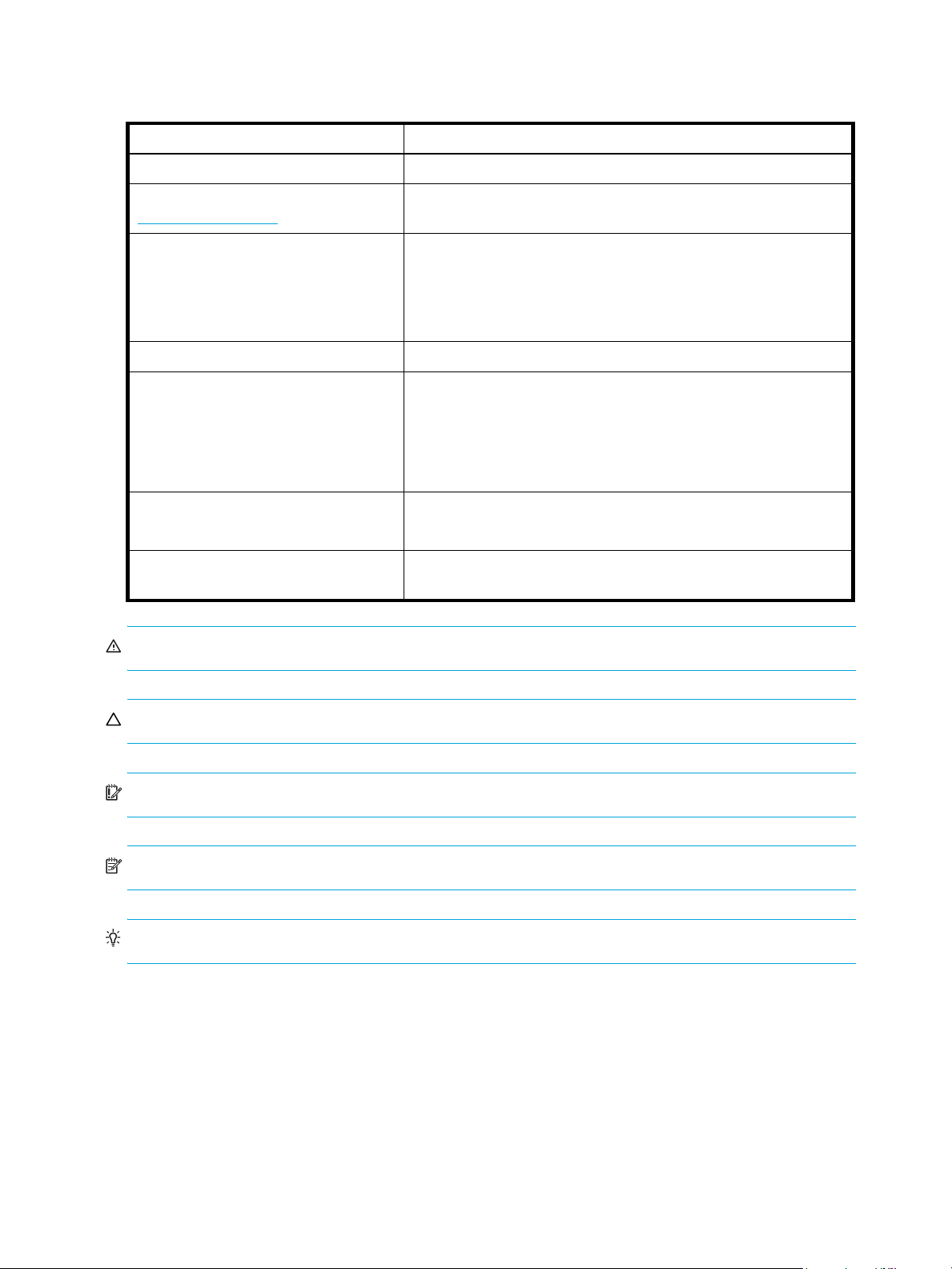
This section describes the features and capabilities of the McDATA 4Gb SAN Switch in an HP p-Class
BladeSystem server blade chassis. The following topics are described:
• Switch LEDs and controls, page 12
• FC ports, page 14
• Ethernet port, page 16
• Switch management, page 16
Fabrics are managed with the McDATA Web Server™ switch management application, the McDATA
Element Manager™ switch management application, and the Command Line Interface (CLI). With the
corresponding Product Feature Enablement (PFE) key, you can manage a single switch through the High
Availability Fabric Manager™ (HAFM) application using McDATA Element Manager™. See the McDATA
4Gb SAN Switch for HP p-Class BladeSystem user guide for information about using the McDATA Web
Server application, McDATA Element Manager application, and the CLI.
Figure 1 McDATA 4Gb SAN Switch
McDATA® 4Gb SAN Switch for HP p-Class BladeSystem installation guide 11
Page 12
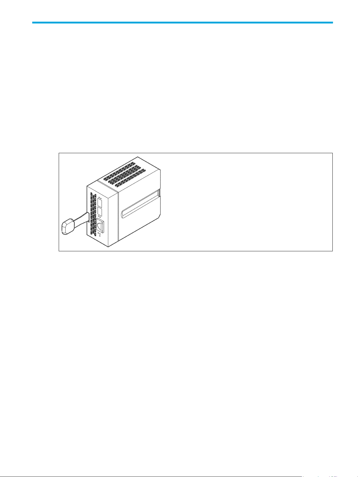
Switch LEDs and controls
The switch LEDs provide information about the switch’s operational status. These LEDs include the Identifier
LED, System Fault LED, and Power LED. The Maintenance button shown in Figure 2 is the only front panel
switch control and is used to reset a switch or to recover a disabled switch.
Maintenance
button
Figure 2 Front panel switch controls and LEDs
Switch LEDs
Switch LEDs
The switch LEDs shown in Figure 3 provide status information about switch operation. See ”External port
LEDs” on page 14 for information about port LEDs.
Figure 3 Switch LEDs
Power LED
Heartbeat LED
System Fault LED
12 General description
Page 13

System Fault LED (amber)
The System Fault LED illuminates to indicate an over temperature condition or a POST error. Also
illuminated on an internal firmware error (heartbeat blink 2), voltage fault, or corrupt config error
(heartbeat blink 4).
Heartbeat LED (green)
The Heartbeat LED indicates the status of the internal switch processor and the results of the POST.
Following a normal power-up, the Heartbeat LED blinks about once per second to indicate that the switch
passed the POST and that the internal switch processor is running. In maintenance mode, the Heartbeat
LED illuminates continuously. See ”Heartbeat LED blink patterns” on page 36 for more information about
Heartbeat LED blink patterns.
Power LED (green)
The Power LED indicates the voltage status at the switch logic circuitry. During normal operation, this LED
illuminates to indicate that the switch logic circuitry is receiving the proper DC voltages. When the switch is
in maintenance mode, this LED is extinguished.
Maintenance button
The Maintenance button shown in Figure 2 is a dual-function momentary switch on the front panel. Its
purpose is to reset the switch or to place the switch in maintenance mode. Maintenance mode sets the IP
address to 10.0.0.1 and provides access to the switch for maintenance purposes when flash memory or
the resident configuration file is corrupted. See ”Recovering a switch using maintenance mode” on
page 41 for more information about using maintenance mode. The Maintenance button can be used if the
user forgets the switch IP address or admin password.
Resetting a switch
Press and release (less than 2 seconds) the Maintenance button using a pointed tool to momentarily to reset
the switch. The switch will respond as follows:
• All switch LEDs will illuminate, then the System Fault LED extinguishes, leaving only the Power LED
illuminated.
• After approximately 1 minute, the POST begins.
• When the POST is complete, the Power LED is illuminated.
Placing the switch in maintenance mode
To place the switch in maintenance mode, perform the following procedure:
1. Isolate the switch from the fabric.
2. Press and hold the Maintenance button with a pointed tool for 10 seconds. The maintenance mode
firmware initializes.
To exit Maintenance mode and return to normal operation, perform the following procedure:
1. Press and release the Maintenance button momentarily to reset the switch.
McDATA® 4Gb SAN Switch for HP p-Class BladeSystem installation guide 13
Page 14
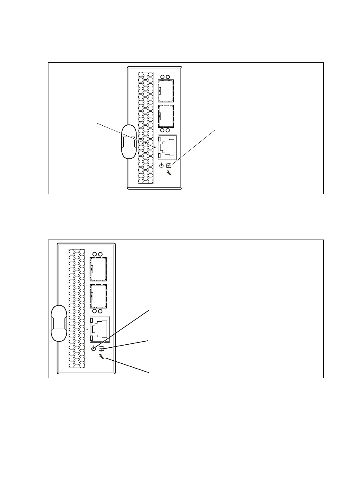
FC ports
The switch has 2 external FC ports through which to connect to devices or other switches, and 8 internal
ports connecting to the server backplane. Each of the external FC ports is served by a Small Form-Factor
Pluggable (SFP) optical transceiver and is capable of 1-Gbps, 2-Gbps, or 4-Gbps transmission. SFPs are
hot-pluggable. External ports can self-discover both the port type and transmission speed when connected
to public devices or other switches. The internal ports operate at 2-Gbps.
The external ports are named Ext:0, Ext:9 and are labeled 0 and 9 as shown in Figure 4. The external port
LEDs provide port login and activity status information. Internal ports are named Int:1–Int:8 and numbered
1–8. The ports 1–8 correspond to server blade slots 1–8 in the server chassis.
0
External ports
9
Figure 4 FC ports
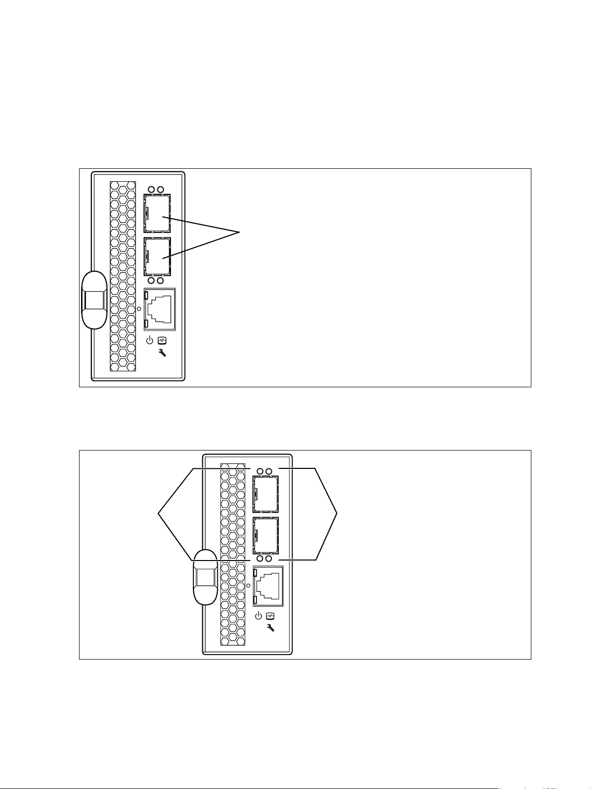
External port LEDs
Each external port has its own Logged-in LED and Activity LED as shown in Figure 5.
Activity LEDs
Figure 5 External port LEDs
0
Logged-in LEDs
9
14 General description
Page 15

Port Logged-in LED (green)
The Logged-in LED indicates the logged-in or initialization status of the connected devices. After successful
completion of the POST, the switch extinguishes all Logged-in LEDs. Following a successful loop
initialization or port login, the switch illuminates the corresponding Logged-in LED. This shows that the port
is properly connected and able to communicate with its attached devices. The Logged-in LED remains
illuminated as long as the port is initialized or logged in. If the connection is broken the Logged-in LED will
be extinguished. If an error occurs that disables the port or the port is taken offline or down, the Logged-in
LED will flash. See ”Logged-in LED diagnostics” on page 38 for more information about the Logged-in LED.
Port Activity LED (green)
The Activity LED indicates that data is passing through the port. Each frame that the port transmits or
receives causes this LED to illuminate for 50 milliseconds. This makes it possible to observe the transmission
of a single frame.
Transceivers
Switches support SFP optical transceivers for the FC ports. A transceiver converts electrical signals to and
from optical laser signals to transmit and receive data. Duplex fiber optic cables plug into the transceivers
which then connect to the devices. An FC port is capable of transmitting at 1-Gbps, 2-Gbps, or 4-Gbps;
however, the transceiver must also be capable of delivering at these rates.
The SFP transceivers are hot pluggable. This means that you can remove or install a transceiver while the
switch is operating without harming the switch or the transceiver. However, communication with the
connected device will be interrupted.
Port types
Switches support auto-discovering fabric ports (F_Port, FL_Port, E_Port). Switches come from the factory with
external ports (0, 9) configured as GL_Ports, and internal ports (1—8) configured as FL_Ports. Generic,
fabric, and expansion ports function as follows:
• A GL_Port self-configures as an FL_Port when connected to a public loop device, as an F_Port when
connected to a single public device (point-to-point), or as an E_Port when connected to another switch.
If the device is a single device on a loop, the GL_Port will attempt to configure first as an F_Port, then if
that fails, as an FL_Port.
• A G_Port self-configures as an F_Port when connected to a single public device (point-to-point), or as
an E_Port when connected to another switch.
• An FL_Port supports a loop of up to 32 public devices. An FL_Port can also configure itself during the
fabric login process as an F_Port when connected to a single public device (point-to-point).
• An F_Port supports a single public device (point-to-point).
E_Ports enable you to expand the fabric by connecting switches with other switches. Switches self-discover
all inter-switch connections. See ”Multiple switch fabrics” on page 21 for more information about multiple
chassis fabrics. See the McDATA 4Gb SAN Switch for HP p-Class BladeSystem user guide for information
about defining port types.
McDATA® 4Gb SAN Switch for HP p-Class BladeSystem installation guide 15
Page 16
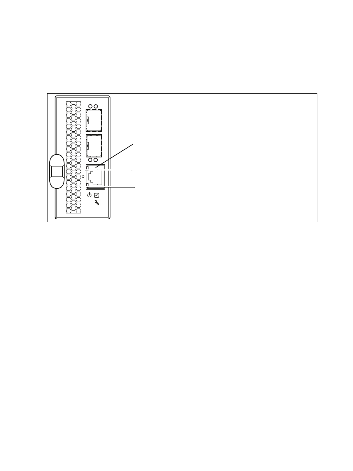
Ethernet port
The Ethernet port shown in Figure 6 is an RJ-45 connector that provides a connection to a management
workstation through a 10/100 Base-T Ethernet cable. A management workstation can be a Windows
®
a Linux
Ethernet connection using the McDATA Web Server, CLI, or SNMP.
The Ethernet port has two LEDs: the Status LED (green) and the Activity LED (green). The Link Status LED
illuminates continuously when an Ethernet connection has been established. The Activity LED illuminates
when data is being transmitted or received over the Ethernet connection.
workstation that is used to configure and manage the switch. You can manage the switch over an
Ethernet port
Activity LED (green)
Status LED (green)
®
or
Figure 6 Ethernet port
Switch management
The switch supports the following management tools:
• McDATA Web Server, page 16
• McDATA Element Manager, page 17
• Command Line Interface, page 17
• Simple Network Management Protocol, page 17
• File Transfer Protocol, page 17
McDATA Web Server
McDATA Web Server is a graphical user interface (GUI) that provides both fabric and switch module
management functions. Because McDATA Web Server resides in the switch firmware, no installation is
needed. You can run one instance of the McDATA Web Server at a time by opening the switch IP address
with an internet browser. McDATA Web Server is best used to manage a single fabric consisting only of
McDATA 4Gb SAN switches. See ”Fabric management workstation” on page 27 for workstation
requirements.
16 General description
Page 17

McDATA Element Manager
IMPORTANT: McDATA Element Manager is available only with the Element Manager PFE key. See
”Installing PFE keys” on page 34 for more information about installing a PFE key. To obtain the McDATA
4Gb SAN Switch serial number and PFE key, follow the step-by-step instructions on the "firmware feature
entitlement request certificate" for the PFE key. One of the license key retrieval options is via the web:
www.webkey.external.hp.com
McDATA Element Manager is a graphical user interface for managing a single McDATA 4Gb SAN Switch
through HAFM. HAFM and McDATA Element Manager are essential tools for managing multiple fabrics or
a single fabric consisting of McDATA 4Gb SAN Switches and McDATA M-series switches.
.
Command Line Interface
The CLI provides monitoring and configuration functions by which the administrator can manage switch.
The CLI is available by Telnet over an Ethernet connection. See the McDATA 4Gb SAN Switch for HP
p-Class BladeSystem user guide for more information.
Simple Network Management Protocol
Simple Network Management Protocol (SNMP) provides monitoring and trap functions for the fabric. The
switch firmware supports SNMP versions 1 and 2, the Fibre Alliance Management Information Base
(FA-MIB) version 4.0, and the Fabric Element Management Information Base (FE-MIB) RFC 2837. Traps can
be formatted using SNMP version 1 or 2.
File Transfer Protocol
File Transfer Protocol (FTP) provides the CLI for exchanging files between the switch and the management
workstation. These files include firmware image files, configuration files, and log files. See the McDATA
4Gb SAN Switch for HP p-Class BladeSystem user guide for an example of using FTP to transfer
configuration backup files.
McDATA® 4Gb SAN Switch for HP p-Class BladeSystem installation guide 17
Page 18

18 General description
Page 19

2 Planning
Consider the following when planning a fabric:
• Devices, page 19
• Device access, page 19
• Performance, page 20
• Multiple switch fabrics, page 21
• Switch services, page 23
• Fabric security, page 24
• Fabric management, page 26
Devices
When planning a fabric, consider the number of public devices and the anticipated demand. This will
determine the number of ports that are needed and in turn the number of switches. See the HP
StorageWorks SAN Design Guide for more information.
For the two external FC ports, the switch uses SFP optical transceivers, but the device you are connecting to
these ports may not. Consider whether the FC ports on the device use SFP or Gigabit Interface Converters
(GBIC) transceivers, and choose fiber optic cables accordingly. Use LC-type cable connectors for SFP
transceivers and SC-type cable connectors for GBIC transceivers. Also consider the transmission speed
compatibility of your devices, HBAs, switches, and SFPs.
Consider the distribution of targets and initiators. An F_Port supports a single public device. An FL_Port can
support up to 32 public devices in an arbitrated loop.
Device access
Consider device access needs within the fabric. Access is controlled by the use of zones and zone sets.
Some zoning strategies include the following:
• Group devices by operating system.
• Separate devices that have no need to communicate with other devices in the fabric or have classified
data.
• Separate devices into department, administrative, or other functional group.
A zone is a named group of devices that can communicate with each other. Membership in a zone can be
defined by switch domain ID and port number, or by device worldwide name (WWN). Devices can
communicate only with devices within the same zone. The switch supports one zone set; that is, the active
zone set. The active zone set contains the zones that determine the current fabric zoning.
Zoning divides the fabric for purposes of controlling device discovery. Devices in the same zone
automatically discover and communicate freely with all other members of the same zone. The following
rules apply to zones:
• Zones that include members from multiple switches need not include the ports of the inter-switch links.
• Zones can overlap; that is, a port can be a member of more than one zone.
• Membership can be defined by domain ID and port number, or port worldwide name.
• Zoning supports FL_Ports and F_Ports.
McDATA® 4Gb SAN Switch for HP p-Class BladeSystem installation guide 19
Page 20

A zoning database is maintained on each switch consisting of the active zone set, all zones, and all zone
members. Table 2 describes the zoning database limits. See the McDATA 4Gb SAN Switch for HP p-Class
BladeSystem user guide for more information.
Table 2 Zoning limits
Limit Description
MaxZoneSets Maximum number of zone sets (1).
MaxZones Maximum number of zones (2047).
MaxTotalMembers Maximum number of zone members (10,000) that can be
MaxZonesInZoneSets Maximum number of zones that are components of the
MaxMembersPerZone Maximum number of members in a zone (10,000)
Performance
The switch supports class 2 and class 3 FC service with a maximum frame size of 2148 bytes at
transmission rates of 1-Gbps, 2-Gbps, or 4-Gbps. An external port adapts its transmission speed to match
that of the device to which it is connected prior to login when the connected device powers up. Related
performance characteristics include the following:
stored in the switch’s zoning database.
active zone set (2047), excluding the orphan zone set, that
can be stored in the switch’s zoning database.
• Distance, page 20
• Bandwidth, page 20
• Latency, page 21
Distance
Consider the physical distribution of devices and switches in the fabric. Choose SFP transceivers that are
compatible with the cable type, distance, FC revision level, and the device. See ”Specifications” on
page 57 for more information about cable types and transceivers.
Each FC port is supported by a data buffer with an 8-credit capacity; that is, 8 maximum sized frames. For
fibre optic cables, this enables full bandwidth over the following approximate distances:
• 13 kilometers at 1-Gbps (0.6 credits/Km)
• 6 kilometers at 2-Gbps (1.2 credits/Km)
• 3 kilometers at 4-Gbps (2.4 credits/km)
Beyond these distances, however, there is some loss of efficiency because the transmitting port must wait
for an R_RDY response before sending the next frame.
Bandwidth
Bandwidth is a measure of the volume of data that can be transmitted at a given transmission rate. An FC
port can transmit or receive at nominal rates of 1-Gbps, 2-Gbps, or 4-Gbps depending on the device to
which it is connected. This corresponds to actual bandwidth values of 106 MB, 212 MB, and 425 MB.
Multiple source ports can transmit to the same destination port if the destination bandwidth is greater than
or equal to the combined source bandwidth. For example, two 1-Gbps source ports can transmit to one
2-Gbps destination port. Similarly, one source port can feed multiple destination ports if the combined
destination bandwidth is greater than or equal to the source bandwidth.
In multiple switch fabrics, each link between switches contributes 106, 212, or 425 MB of bandwidth
between those switches depending on the speed of the link. When additional bandwidth is needed
between devices, increase the number of links between the connecting switches.
20 Planning
Page 21

Latency
Switch latency is a measure of how fast a frame travels through the switch from one switch port to another.
The factors that affect latency include transmission rate and the source/destination port relationship as
shown in Table 3.
Table 3 Port-to-port latency
Destination Rate
Gbps 1 2 4
1 < 0.6 µsec < 0.8 µsec
2 < 0.5 µsec < 0.4 µsec < 0.4 µsec
4 < 0.4 µsec < 0.3 µsec < 0.3 µsec
Source Rate
1. Based on minimum frame size of 36 bytes. Latency increases for larger frame sizes.
Multiple switch fabrics
By connecting switches together you can expand the number of available ports for devices. Each switch in
the fabric is identified by a unique domain ID, and the fabric can automatically resolve domain ID
conflicts. Because the FC ports are self-configuring, you can connect switches together in a wide variety of
topologies. See the SAN Design Reference Guide for topology guidelines.
Optimizing device performance
1
< 0.8 µsec
1
1
When choosing a topology for a multiple switch fabric, you should also consider the locality of your server
and storage devices and the performance requirements of your application. Storage applications such as
video distribution, medical record storage/retrieval or real-time data acquisition can have specific latency
or bandwidth requirements.
The switch provides the lowest latency of any product in its class. See ”Performance” on page 20 for
information about latency. However, the highest performance is achieved on FC switches by keeping traffic
within a single switch instead of relying on ISLs. Therefore, for optimal device performance, place devices
on the same switch under the following conditions:
• Heavy I/O traffic between specific server and storage devices.
• Distinct speed mismatch between devices
McDATA® 4Gb SAN Switch for HP p-Class BladeSystem installation guide 21
Page 22

Domain ID, principal priority, and domain ID lock
The following switch configuration settings affect multiple switch fabrics:
• Domain ID
• Principal priority
• Domain ID lock
The domain ID is a unique number that identifies each switch in a fabric. The valid domain ID range
depends on the interoperability mode:
• When the interoperability mode is Standard, the domain ID can be 97–127.
• When the interoperability mode is McDATA Fabric Mode, the domain ID can be 1–31.
The principal priority is a number (1–255) that determines the principal switch which manages domain ID
assignments for the fabric. The switch with the highest principal priority (1 is high, 255 is low) becomes the
principal switch. If the principal priority is the same for all switches in a fabric, the switch with the lowest
WWN becomes the principal switch.
The domain ID lock allows (False–Default) or prevents (True) the reassignment of the domain ID on that
switch. Switches come from the factory with the domain ID set to 97, the domain ID lock set to False, and
the principal priority set to 254. See the McDATA 4Gb SAN Switch for HP p-Class BladeSystem user guide
for information about changing the domain ID and domain ID lock using McDATA Web Server or McDATA
Element Manager. See the Set Config command in the McDATA 4Gb SAN Switch for HP p-Class
BladeSystem user guide for information about changing the default domain ID, domain ID lock, and
principal priority parameters.
An unresolved domain ID conflict means that the switch with the higher WWN will isolate as a separate
fabric, and the Logged-in LEDs will flash green to show the affected ports. If you connect a new switch to
an existing fabric with its domain ID unlocked, and a domain ID conflict occurs, the new switch will isolate
as a separate fabric. However, you can remedy this by resetting the new switch or taking it offline then
back online. The principal switch will reassign the domain ID and the switch will join the fabric. It is
recommended to assign sequential domain IDs to switches to avoid domain ID conflicts and to keep port
addressing the same.
NOTE: Domain ID reassignment is not reflected in zoning that is defined by domain ID/port number pair.
You must reconfigure zones that are affected by domain ID reassignment. To prevent zoning definitions
from becoming invalid under these conditions, lock the domain IDs using McDATA Web Server, McDATA
Element Manager, or the Set Config command with the Switch operand. HP recommeds defining zone
members by WWN.
22 Planning
Page 23

Switch services
You can configure your switch to suit the demands of your environment by enabling or disabling a variety
of switch services. Familiarize yourself with the following switch services and determine which ones you
need:
• Telnet—Provides for the management of the switch over a Telnet connection. Disabling this service is not
recommended. The default is enabled.
• Secure Shell (SSH)—Provides for secure remote connections to the switch using SSH. Your workstation
must also use an SSH client. The default is disabled.
• Switch Management—Provides for out-of-band management of the switch with Telnet, McDATA Web
Server, and CIM. The switch can be managed by SNMP supported management programs. SNMP is
supported both inband and out-of-band. If this service is disabled, the switch can only be managed
inband. The default is enabled.
• Inband Management—Provides for the management of the switch over FC using the McDATA Web
Server, SNMP, or management server. If you disable inband management and out of band
management, you can no longer communicate with that switch. The default is enabled. Access to an
entry switch via ethernet is required.
• Secure Socket Layer (SSL)—Provides for secure SSL connections for the McDATA Web Server, McDATA
Element Manager, and CIM. To enable secure SSL connections, you must first synchronize the date and
time on the switch and workstation. Enabling SSL automatically creates a security certificate on the
switch. The default is disabled.
• Embedded GUI—Provides for access to both McDATA Web Server and McDATA Element Manager.
McDATA Web Server enables you to point at a switch with an internet browser and run switch
management application through the browser. McDATA Element Manager enables you to manage the
switch through HAFM. The default is enabled.
• SNMP—Provides for the management of the switch through third-party applications that use the SNMP.
Security consists of a read community string and a write community string that serve as passwords that
control read and write access to the switch. These strings are set at the factory to these well-known
defaults and should be changed if SNMP is to be enabled. Otherwise, you risk unwanted access to the
switch. The default is enabled.
• Network Time Protocol (NTP)—Provides for the synchronizing of switch and workstation dates and times
with an external NTP server. This helps to prevent invalid SSL certificates and timestamp confusion in the
event log. The default is disabled.
• Common Information Module (CIM)—Provides for the management of the switch through third-party
applications that use CIM. The default is enabled.
• File Transfer Protocol (FTP)—Provides for transferring files rapidly between the workstation and the
switch. The default is enabled.
• Management Server (MS)—Enables or disables the management of the switch through third-party
applications that are compliant with the FC GS-3 Management Server Specification. The default is
disabled.
McDATA® 4Gb SAN Switch for HP p-Class BladeSystem installation guide 23
Page 24

Fabric security
An effective security profile begins with a security policy that states the requirements. A threat analysis is
needed to define the plan of action followed by an implementation that meets the security policy
requirements. Internet portals, such as remote access and E-mail, usually present the greatest threats. Fabric
security should also be considered in defining the security policy.
Most fabrics are located at a single site and are protected by physical security, such as key-code locked
computer rooms. For these cases, security methods such as user passwords for equipment and zoning for
controlling device access are satisfactory.
Fabric security is needed when security policy requirements are more demanding: for example, when
fabrics span multiple locations and traditional physical protection is insufficient to protect the IT
infrastructure. Another benefit of fabric security is that it creates a structure that helps prevent unintended
changes to the fabric.
Fabric security consists of the following:
• Connection security, page 24
• Device security, page 25
• User account security, page 26
Connection security
Connection security provides an encrypted data path for switch management methods. The switch supports
the SSH protocol for the CLI and the SSL protocol for management applications such as McDATA Web
Server, McDATA Element Manager, and CIM.
The SSL handshake process between the workstation and the switch involves the exchanging of certificates.
These certificates contain the public and private keys that define the encryption. When the SSL service is
enabled, a certificate is automatically created on the switch. The workstation validates the switch certificate
by comparing the workstation date and time to the switch certificate creation date and time. For this
reason, it is important to synchronize the workstation and switch with the same date, time, and time zone.
The switch certificate is valid 24 hours before its creation date and 365 days after its creation date. If the
certificate should become invalid, see the Create command in the McDATA 4Gb SAN Switch for HP
p-Class BladeSystem user guide for information about creating a certificate.
Consider your connection security requirements for the CLI, and management applications such as
McDATA Web Server. If SSL connection security is required, also consider using NTP to synchronize
workstations and switches.
• See System operand of the Set Setup command in the McDATA 4Gb SAN Switch for HP p-Class
BladeSystem user guide for information about enabling the NTP client on the switch and configuring the
NTP server.
• See the Set command in the McDATA 4Gb SAN Switch for HP p-Class BladeSystem user guide for
information about setting the time zone.
24 Planning
Page 25

Device security
IMPORTANT: Device security is available only with the McDATA SANtegrity™ Enhanced PFE key. See
”Installing PFE keys” on page 34 for more information about installing a PFE key. To obtain the McDATA
4Gb SAN Switch serial number and PFE key, follow the step-by-step instructions on the "firmware feature
entitlement request certificate" for the PFE key. One of the license key retrieval options is via the web:
www.webkey.external.hp.com
Device security provides for the authorization and authentication of devices that you attach to a switch. You
can configure a switch with a group of devices against which the switch authorizes new attachments by
devices, other switches, or devices issuing management server commands. Device security is configured
through the use of security sets and groups. A group is a list of device worldwide names that are
authorized to attach to a switch. There are three types of groups: one for other switches (ISL), another for
devices (port), and a third for devices issuing management server commands (MS). A security set is a set of
up to three groups with no more than one of each group type. The security configuration is made up of all
security sets on the switch. The security database has the following limits:
• Maximum number of security sets is 4.
• Maximum number of groups is 16.
• Maximum number of members in a group is 1000.
• Maximum total number of group members is 1000.
In addition to authorization, the switch can be configured to require authentication to validate the identity
of the connecting switch, device, or host. Authentication can be performed locally using the switch’s
security database, or remotely using a Remote Dial-In User Service (RADIUS) server such as Microsoft
RADIUS. With a RADIUS server, the security database for the entire fabric resides on the server. In this
way, the security database can be managed centrally, rather than on each switch. You can configure up to
five RADIUS servers to provide failover.
.
®
You can configure the RADIUS server to authenticate just the switch or both the switch and the initiator
device if the device supports authentication. When using a RADIUS server, every switch in the fabric must
have a network connection. A RADIUS server can also be configured to authenticate user accounts as
described in ”User account security” on page 26. A secure connection is required to authenticate user
logins with a RADIUS server. See ”Connection security” on page 24 for more information.
Consider the devices, switches, and management agents and evaluate the need for authorization and
authentication. Also consider whether the security database is to be distributed on the switches or
centralized on a RADIUS server and how many servers to configure.
McDATA® 4Gb SAN Switch for HP p-Class BladeSystem installation guide 25
Page 26

User account security
User account security consists of the administration of account names, passwords, expiration date, and
authority level. If an account has Admin authority, all management tasks can be performed by that account
in McDATA Web Server, McDATA Element Manager, and the Telnet CLI. Otherwise only monitoring tasks
are available. The default account name, Admin, is the only account that can create or change account
names and passwords. Account names and passwords are always required when connecting to a switch.
Authentication of the user account and password can be performed locally using the switch’s user account
database or it can be done remotely using a RADIUS server such as Microsoft
user logins on a RADIUS server requires a secure management connection to the switch. See ”Connection
security” on page 24 for information about securing the management connection. A RADIUS server can
also be used to authenticate devices and other switches as described in ”Device security” on page 25.
Consider your management needs and determine the number of user accounts, their authority needs, and
expiration dates. Also consider the advantages of centralizing user administration and authentication on a
RADIUS server.
NOTE: If the same user account exists on a switch and its RADIUS server, that user can login with either
password, but the authority and account expiration will always come from the switch database.
Fabric management
Your choice of management tool depends on the number of fabrics you want to manage and the types of
switches:
• The CLI provides configuration and control for one and only one McDATA 4Gb SAN Switch through a
Telnet session.
• McDATA Web Server provides configuration and control for one fabric made up exclusively of McDATA
4Gb SAN Switches.
• HAFM with McDATA Element Manager provides configuration and control for multiple fabrics that
consist of a mix of McDATA 4Gb SAN Switches and M-series McDATA switches. McDATA Element
manager requires a PFE key and must be launched from HAFM.
®
RADIUS. Authenticating
A switch supports a combined maximum of 19 logins reserved as follows:
• 4 logins or sessions for internal applications such as management server and SNMP
• 9 high priority Telnet sessions
• 6 McDATA Web Server, McDATA Element Manager, or Telnet logins. Additional logins will be refused.
Consider your fabric management needs including the number of fabrics and types of switches. Also
consider the number of management workstations that are are needed and their operating systems. See
”Fabric management workstation” on page 27 for information about workstation requirements.
26 Planning
Page 27

3Installation
The McDATA 4Gb SAN Switch for HP p-Class BladeSystem provides integrated FC switch connectivity for
single and dual density p-Class blade servers. The switch is compatible with any combination of server
blade models in the HP BladeSystem enclosure that connects to the Ethernet Interconnect switch. These FC
signal conditioning cards provide FC signal pass-through connectivity to ProLiant Blade servers. This
section describes how to install and configure the McDATA 4Gb SAN Switch. It also describes how to load
new firmware and how to recover a disabled switch.
Preparing for installation
CAUTION: Installation of the HP ProLiant BL p-Class FC Signal Conditioning Cards should be performed
by individuals who are both qualified to service computer equipment and trained in the dangers
associated with products capable of producing hazardous energy levels.
To prevent damage to the system, be aware of the precautions you need to follow when setting up the
system or handling parts. A discharge of static electricity from a finger or other conductor may damage
system boards or other static-sensitive devices. This type of damage may reduce the life expectancy of the
device.
Observe the following guidelines during installation:
1. Install the FC signal conditioning cards into the HP p-Class BladeSystem Interconnect Switches.
2. Install the Interconnect switch into one of the interconnect bays, which are the left-most (side A) and
right-most (side B) bays on the front side of the server blade enclosure.
3. Install the SAN Switch into the top left-most or top right-most bay on the rear side of the blade enclosure
corresponding to the installed Interconnect switch.
4. Install the included small form-factor pluggable optical transceivers (SFP modules) into the appropriate
FC ports of the SAN Switch.
For additional information about Storage Area Network (SAN) connectivity, see the SAN Design Reference
Guide located at http://h18000.www1.hp.com/products/storageworks/san/documentation.html.
Fabric management workstation
The requirements for fabric management workstations running McDATA Web Server are described in
Table 4:
Table 4 Management workstation requirements
Component Requirement
Operating System Windows 2000/2003
®
Linux
Red Hat® EL 3.x, 4.x
Memory 256 MB or more
Processor 500 MHz or faster
Hardware
Internet Browser Microsoft
Telnet workstations require an RJ-45 Ethernet port and an operating system with a Telnet client.
RJ-45 Ethernet port
Netscape Navigator
Mozilla™ 1.02 or later
Java 2 Runtime Environment to support the McDATA Web Server.
®
Internet Explorer® 5.0 or later
®
4.72 or later
McDATA® 4Gb SAN Switch for HP p-Class BladeSystem installation guide 27
Page 28

Environmental conditions
Consider the factors that affect the climate in your facility such as equipment heat dissipation and
ventilation. The switch requires the following operating conditions:
• Operating temperature range: 5–35°C (41–95°F)
• Relative humidity: 5–90%, non-condensing
Upgrading the Interconnect switch
CAUTION: First installation of a SAN Switch into an Interconnect switch requires installation of the FC
signal conditioning card into the Interconnect switch, if not already installed, shall result in the loss of
Ethernet network communication between the server blade network ports that are connected through the
Interconnect switch and the segment of Ethernet network infrastructure whose ports need to communicate.
For continued Blade server network communication and services availability, redirect critical
high-availability services or applications to the redundant network ports available on those Blade servers
that are connected through the redundant Interconnect switch in the enclosure.
1. Power down the Interconnect switch.
2. Remove the Interconnect switch.
3. Remove the Interconnect switch cover. Note that some models of the Interconnect switch require a
screwdriver to release a latch which loosens the cover.
4. Install the FC signal conditioning card if not already installed.
5. Replace the Interconnect switch cover and insert the Interconnect switch back into the enclosure.
Installing the SAN Switch
Remove the protective foam from the prongs on the back of the SAN Switch. Install the SAN Switch into the
back of the Interconnect switch. The handle of the SAN Switch should always be on the left.
Figure 7 Installing the SAN Switch
28 Installation
Page 29

Connect the management workstation to the switch
Connect the management workstation to the switch in the following ways:
• Indirect Ethernet connection from the management workstation to the switch RJ-45 Ethernet connector
through an Ethernet switch or a hub. This requires a 10/100 Base-T straight cable as shown in
Figure 8. With this method, you can manage the switch with the McDATA Web Server application or
the CLI.
• Direct Ethernet connection from the management workstation to the switch RJ-45 Ethernet connector.
This requires a 10/100 Base-T cross-over cable as shown in Figure 8. With this method, you can
manage the switch with the McDATA Web Server application or the CLI.
Indirect Ethernet
RJ-45 connection
81
8
7
6
5
4
3
2
1
Figure 8 Ethernet cable connections
The default IP address of a new switch is 10.0.0.1. Many management workstations are not configured to
communicate with the 10.0.0 subnet. Use the McDATA Web Server Configuration Wizard to set the IP
address of a new switch without re-configuring the management workstation.
To establish an Ethernet connection, perform the following procedure:
1. Connect a 10/100 Base-T cross-over cable from an RJ-45 port on the management workstation directly
to the RJ-45 Ethernet port; or a 10/100 Base-T straight cable indirectly over an Ethernet network.
2. Open a command line window.
3. Enter the following command with the switch IP address to start a Telnet session. The default IP address
is 10.0.0.1
telnet 10.0.0.1
4. Log in to the switch. Enter the default account name (admin) and password (password).
Switch Login: admin
Password: ********
8
7
6
5
4
3
2
1
Direct Ethernet
RJ-45 connection
81
8
7
6
5
4
3
2
1
8
7
6
5
4
3
2
1
Start McDATA Web Server or McDATA Element Manager
After the switch is operational, open the McDATA Web Server by entering the switch IP address in an
internet browser. The default IP address is 10.0.0.1. If your workstation does not have the Java 2 Run Time
Environment program, you will be prompted to download it.
Open McDATA Element Manager from HAFM. In HAFM, add the switch IP address to the discovery list.
Locate and double click the switch in the fabric map to open. You can also select the switch and select
Element Manager from the application list. See your HAFM documentation for information about using
HAFM.
McDATA® 4Gb SAN Switch for HP p-Class BladeSystem installation guide 29
Page 30

Configure the switch
You can configure the switch using the McDATA Web Server application, the McDATA Element Manager
application, or the CLI. Using McDATA Web Server or McDATA Element Manager, select the Open
Configuration Wizard option in the Initial Start Dialog. Click Proceed to configure the switch. The
Configuration wizard explains and prompts you for the following configuration information:
• Archive template file
• Switch domain ID
• Domain ID lock (locked/unlocked)
• Switch name
• Permanent IP address
• Permanent subnet mask
• Permanent gateway address
• Permanent network discovery method
• Date and time
• Admin account password
• Create a configuration archive
NOTE: See ”Factory configuration defaults” on page 61 for information about configuration default
values.
To configure the switch using the CLI, perform the following procedure:
1. Enter the default switch IP address to start a Telnet session. Enter the default account name (admin) and
password (password) to log in to the switch.
telnet 10.0.0.1
Switch Login: admin
Password: *******
2. Start an admin session and enter the Set Setup System command. Enter the values you want for
switch IP address (Eth0NetworkAddress) and the network mask (Eth0NetworkMask). See the McDATA
4Gb SAN Switch for HP p-Class BladeSystem user guide for more information about this command.
McDATA4GbSAN #> admin start
McDATA4GbSAN (admin) #> set setup system
3. Open a Config Edit session and use the Set Config command to modify the switch configuration.
See the McDATA 4Gb SAN Switch for HP p-Class BladeSystem user guide for more information about
these commands.
30 Installation
Page 31

Cable devices to the switch
Two 4-Gb SFPs ship with each McDATA 4Gb SAN Switch. It is recommended to use these SFPs rather than
the 2Gb SFPs that ship with the BladeSystem. Connect cables to the SFP transceivers and their
corresponding devices, and then energize the devices. Device host bus adapters (HBA) can have SFP (or
SFF) transceivers or GigaBit Interface Converters (GBIC). LC-type duplex fiber optic cable connectors are
designed for SFP transceivers, while SC-type connectors are designed for GBICs. Duplex cable connectors
are keyed to ensure proper orientation. Choose the fiber optic cable with the connector combination that
matches the device host bus adapter. Be sure to keep the rubber plugs in the unused transceivers to prevent
dust and ambient light from entering the SFPs.
Figure 9 Installing SFPs in the SAN Switch
GL_Ports self configure as FL_Ports when connected to loop of public devices or F_Ports (point-to-point)
when connected to a single device. G_Ports self configure as F_Ports when connected to single public
devices. Both GL_Ports and G_Ports self configure as E_Ports when connected to another switch.
Installing firmware
The switch comes with current firmware installed. You can upgrade the firmware from the management
workstation as new firmware becomes available. You can use the McDATA Web Server application, the
McDATA Element Manager application, or the CLI to install new firmware.
You can load and activate firmware on an operating switch without disrupting data traffic or having to
re-initialize attached devices. If you attempt to perform a non-disruptive activation without satisfying the
following conditions, the switch will perform a disruptive activation:
• The current firmware version is a version that supports upgrading to the new version.
• No changes are being made to switches in the fabric including powering up, powering down,
disconnecting or connecting ISLs, and switch configuration changes.
• No port in the fabric is in the diagnostic state.
• No zoning changes are being made in the fabric.
• No changes are being made to attached devices including powering up, powering down,
disconnecting, connecting, and HBA configuration changes.
Ports that are stable when the non-disruptive activation begins, then change states, will be reset. When the
non-disruptive activation is complete, McDATA Web Server and McDATA Element Manager sessions
reconnect automatically. However, Telnet sessions must be restarted manually.
McDATA® 4Gb SAN Switch for HP p-Class BladeSystem installation guide 31
Page 32

Using McDATA Web Server or McDATA Element Manager to install firmware
Installing firmware involves loading, unpacking, and activating the firmware image on the switch. McDATA
Web Server and McDATA Element Manager do this in one operation. To provide consistent performance
throughout the fabric, ensure that all McDATA 4Gb SAN Switch for HP p-Class BladeSystem switches are
running the same version of firmware. Verify that this version of firmware is compatible with the firmware of
other McDATA switch models in the fabric.
The pending firmware version will differ from the active version during the brief period while the switch is
resetting to activate the firmware. Firmware management tools enable you to install and activate new
firmware.
During a hotreset operation, fabric services will be unavailable for a short period (30-75 seconds). To
ensure that an a Non-Disruptive Code Load and Activation (NDCLA) operation is successful, verify that all
administrative changes to the fabric (if any) are complete. When you need to do NDCLA/hotreset to
multiple switches, only perform the NDCLA/hotreset on one switch at a time, and allow a 75 second wait
before performing the NDCLA/hotreset operation on the next switch.
CAUTION: Changes to the fabric may disrupt the NDCLA process. Common administrative operations
that change the fabric include zoning modifications, adding, moving or removing devices attached to the
switch fabric (this includes powering up or powering down attached devices), and adding, moving or
removing ISLs or other connections.
To install firmware using McDATA Web Server or McDATA Element Manager, perform the following
procedure:
1. Double-click a switch in the topology display to open the faceplate display.
2. Select Switch > Load Firmware.
3. Click Browse, and browse for and select the firmware file to be loaded in the Load Firmware dialog.
4. Click Start to begin the firmware load process. You will be shown a message warning you that the
switch will be reset to activate the firmware.
5. Click OK to continue firmware installation, or click Cancel to cancel the firmware installation.
The switch will attempt a hot reset, if possible, to activate the firmware without disrupting data traffic.
During a non-disruptive activation, all Logged-In LEDs are extinguished for several seconds. If a
non-disruptive activation is not possible, an error message will be shown. To activate the firmware
image, the user may either resolve the error described in the message and perform a hot reset on the
switch or simply reset the switch (disruptive).
After an NDCLA operation is complete, management connections must be re-initiated:
• McDATA Web Server and McDATA Element Manager sessions will re-connect automatically
• Telnet sessions must be restarted manually.
Applicable code versions:
• Future switch code releases will be upgraded non-disruptively unless specifically indicated in its
associated release notes
• An NDCLA operation to previous switch code releases is not supported.
32 Installation
Page 33

Using the CLI to install firmware
To install firmware using the CLI when a File Transfer Protocol (FTP) server is present on the management
workstation, use the Firmware Install command. See the McDATA 4Gb SAN Switch for HP p-Class
BladeSystem user guide for information about this command.This command is disruptive to the fabric
traffic.
1. Enter the following command to download the firmware from a remote host to the switch, install the
firmware, then reset the switch to activate the firmware. If possible, a non-disruptive activation will be
performed.
McDATA4GbSAN (admin) #> firmware install
Warning: Installing new firmware requires a switch reset. Continuing
with this action will terminate all management sessions, including any
Telnet sessions. When the firmware activation is complete, you may log
in to the switch again.
Do you want to continue? [y/n]: y
Press 'q' and the ENTER key to abort this command.
2. Enter your account name on the remote host and the IP address of the remote host. When prompted for
the source file name, enter the path for the firmware image file.
User Account : johndoe
IP Address : 10.20.20.200
Source Filename : 5.2.x.xx.xx_mpc
3. When prompted to install the new firmware, press Y to continue or press N to cancel. This is the last
opportunity to cancel.
About to install image. Do you want to continue? [y/n] y
Connected to 10.20.20.200 (10.20.20.200).
220 localhost.localdomain FTP server (Version wu-2.6.1-18) ready.
4. Enter the password for your account name. The firmware will now be downloaded from the remote host
to the switch, installed, and activated. The firmware is installed and the switch is automatically reset.
331 Password required for johndoe.
Password:******
230 User johndoe logged in.
bin
200 Type set to I.
verbose
Verbose mode off.
This may take several seconds...
The switch will now reset.
Connection closed by foreign host.
McDATA® 4Gb SAN Switch for HP p-Class BladeSystem installation guide 33
Page 34

Installing PFE keys
A PFE key is a password that you can purchase from your switch distributor or authorized reseller to enable
particular features in your switch. The following features are available with a PFE key:
• SANtegrity Enhanced: Enables device security on the switch.
• Element Manager: Enables the McDATA Element Manager switch management application through
HAFM.
NOTE: To obtain the McDATA 4Gb SAN Switch serial number and PFE key, follow the step-by-step
instructions on the "firmware feature entitlement request certificate" for the PFE key. One of the license key
retrieval options is via the web: www.webkey.external.hp.com
To install a PFE key, perform the following procedure:
1. Open the faceplate display of the switch on which you want to install the PFE key.
2. Select Switch > Features to open the Feature Licenses dialog shown in Figure 10.
.
Figure 10 Features Licenses dialog
3. Click Add in the Feature Licenses dialog to open the Add License Key dialog shown in Figure 11.
Figure 11 Add License Key dialog
4. Enter the license key in the Key field in the Add License Key dialog.
5. Click Get Description to display the PFE key description in the Description field.
6. Click Add Key. Allow a minute or two to complete.
34 Installation
Page 35

4 Diagnostics and troubleshooting
Diagnostic information about the switch is available through the switch LEDs and the port LEDs. Diagnostic
information is also available through the McDATA Web Server and CLI event logs and error displays. This
section describes the following types of diagnostics:
• ”Switch diagnostics” on page 35 describes the Power LED and System Fault LED indications.
• ”Power On Self Test diagnostics” on page 36 describe the Heartbeat LED and the port Logged-in LED
indications.
This section also describes how to use maintenance mode to recover a disabled switch.
Switch diagnostics
Switch diagnostics are indicated by the switch LEDs as shown in Figure 12.
Power LED
Figure 12 Switch LED diagnostics
The following conditions are described:
• Power LED is extinguished, page 35
• System Fault LED is illuminated, page 35
Power LED is extinguished
The Power LED illuminates to indicate that the switch logic circuitry is receiving proper voltages. If the Power
LED is extinguished, contact your authorized maintenance provider.
System Fault LED is illuminated
The System Fault LED illuminates to indicate that the switch logic circuitry is overheating, or that a POST
error has occurred. The System Fault LED is always accompanied by a Heartbeat LED error blink code. If
the System Fault LED illuminates, identify the Heartbeat LED error blink pattern and take the necessary
actions. See ”Heartbeat LED blink patterns” on page 36. The System Fault LED is also illuminated on an
internal firmware error, corrupt configuration, and voltage fault (input power never is turned off once the
switch is powered on even during a voltage fault).
Heartbeat LED
System Fault LED
McDATA® 4Gb SAN Switch for HP p-Class BladeSystem installation guide 35
Page 36

Power On Self Test diagnostics
The switch performs a series of tests as part of its power-up procedure. The Power On Self Test (POST)
diagnostic program performs the following tests:
• Checksum tests on the boot firmware in PROM and the switch firmware in flash memory
• Internal data loopback test on all ports
• Access and integrity test on the ASIC
During the POST, the switch logs any errors encountered. Some POST errors are critical, others are not. The
switch uses the Heartbeat LED and the Logged-in LED to indicate switch and port status. A critical error
disables the switch so that it will not operate. A non-critical error allows the switch to operate, but disables
the ports that have errors. Whether the problem is critical or not, contact your authorized maintenance
provider.
If there are no errors, the Heartbeat LED blinks at a steady rate of once per second. If a critical error
occurs, the Heartbeat LED will show an error blink pattern and the System Fault LED will illuminate. If there
are non-critical errors, the switch disables the failed ports and flashes the associated Logged-in LEDs. See
”Heartbeat LED blink patterns” on page 36 for more information about Heartbeat LED blink patterns.
Heartbeat LED blink patterns
The Heartbeat LED indicates the operational status of the switch. When the POST completes with no errors,
the Heartbeat LED blinks at steady rate of once per second. When the switch is in maintenance mode, the
Heartbeat LED illuminates continuously. See ”Recovering a switch using maintenance mode” on page 41
for more information about maintenance mode. All other blink patterns indicate critical errors. In addition
to producing a Heartbeat error blink patterns, a critical error also illuminates the System Fault LED.
The Heartbeat LED shows an error blink pattern for the following conditions:
• 2 blinks - Internal firmware failure blink pattern, page 36
• 3 blinks - System error blink pattern, page 36
• 4 blinks - Configuration file system error blink pattern, page 37
• 5 blinks - Over temperature blink pattern, page 38
Internal firmware failure blink pattern
An internal firmware failure blink pattern is 2 blinks followed by a two second pause. The 2-blink error
pattern indicates that the firmware has failed, and that the switch must be reset. Momentarily press and
release the Maintenance button to reset the switch. Gather logging data, call support before resetting the
switch.
2 seconds
System error blink pattern
A system error blink pattern is 3 blinks followed by a two second pause. The 3-blink error pattern indicates
that a POST failure or a system error has left the switch inoperable. If a system error occurs, contact your
authorized maintenance provider. Momentarily press and release the Maintenance button to reset the
switch.
2 seconds
36 Diagnostics and troubleshooting
Page 37

Configuration file system error blink pattern
A configuration file system error blink pattern is 4 blinks followed by a two second pause. The 4-blink error
pattern indicates that a configuration file system error has occurred, and that the switch configuration file
must be recreated. See ”Recovering a switch using maintenance mode” on page 41 for more information.
2 seconds
To recreate the configuration file, perform the following procedure:
CAUTION: Recreating the configuration file will delete all switch configuration settings.
1. Press and hold the Maintenance button for 10 seconds to place the switch in maintenance mode. See
”Recovering a switch using maintenance mode” on page 41 for more information about placing the
switch in maintenance mode.
2. Enter the default IP address 10.0.0.1. and press Enter to establish a Telnet session
telnet 10.0.0.1
3. Enter the account name (prom) and password (prom), and press Enter.
Switch login: prom
Password: xxxx
4. Enter 6 (Remake Filesystem) and press Enter to recreate the configuration file using the following menu.
0) Exit
1) Image Unpack
2) Reset Network Config
3) Reset User Accounts to Default
4) Copy Log Files
5) Remove Switch Config
6) Remake Filesystem
7) Reset Switch
8) Update Boot Loader
Option: 6
5. Enter 7 and press Enter to reset the switch. Exit maintenance mode after the recreate process is
complete.
6. Perform the following procedure to restore the configuration file if a previously saved configuration file is
available for the switch.
a. Enter the following on the command line and press Enter to establish communications with the
switch using the File Transfer Protocol (FTP).
>ftp 10.0.0.1
b. Enter the following account name and password, and press Enter.
user:images
password:images
c. Enter the following command and press Enter to activate binary mode and copy the configuration
file from the workstation to the switch. The configuration file must be named configdata.
ftp>bin
ftp>put configdata
d. Enter the following command and press Enter to close the FTP session.
ftp>quit
McDATA® 4Gb SAN Switch for HP p-Class BladeSystem installation guide 37
Page 38

e. Enter one of the following commands and press Enter to establish communications with the switch
using Telnet.
telnet xxx.xxx.xxx.xxx
or
telnet switchname
where xxx.xxx.xxx.xxx is the switch IP address and switchname is the switch name associated with
the IP address.
f. Enter an account name and password, and press Enter after the Telnet window opens and prompts
you for a login. The default account name is admin. The default password is password.
g. Enter the following command and press Enter to open an admin session to acquire the necessary
authority.
McDATA4GbSAN $>admin start
h. Enter the following command and press Enter to restore the configuration file. When the restore is
complete, the switch will reset.
McDATA4GbSAN (admin) $>config restore
Over temperature blink pattern
An over temperature blink pattern is 5 blinks followed by a two second pause. The 5-blink error pattern
indicates that the air temperature inside the switch has exceeded the failure temperature threshold. The
failure temperature threshold is 70° C.
2 seconds
If the Heartbeat LED shows the over temperature blink pattern, consider the ambient air temperature. Make
necessary corrections. If the condition remains, power down the switch and contact your authorized
maintenance provider.
Logged-in LED diagnostics
Port diagnostics are indicated by the Logged-in LED for each port as shown in Figure 13.
Figure 13 Logged-in LED diagnostics
The Logged-in LED has three indications:
Logged-in LEDs
• Continuous illumination—A device is logged in to the port.
• Flashing once per second—Another switch is logging in to the port, or the port is administratively
offline.
• Flashing twice per second—The port is down or an error has occurred.
38 Diagnostics and troubleshooting
Page 39

If a Logged-in LED is flashing twice per second, review the event browser for alarm messages regarding the
affected port. You can also inspect the alarm log using the Show Alarm command. If there is an error,
alarm messages may point to one or more of the following conditions:
• E_Port isolation, page 39
• Excessive port errors, page 40
E_Port isolation
A Logged-in LED error indication is often the result of E_Port isolation. An isolated E_Port is indicated by a
red link in the McDATA Web Server topology display. E_Port isolation can be caused by the following:
• Security failure
• Port type is F_Port or FL_Port and is connected to another switch (should be configured as G or GL)
• Conflicting domain IDs
• Incompatible fabric interop modes
• Conflicting timeout values
• Conflicting zone membership between active zone sets
See the McDATA 4Gb SAN Switch for HP p-Class BladeSystem user guide for information about how to
change domain IDs, timeout values, and edit zoning.
Using the McDATA Web Server, review the event browser and perform the following procedure to
diagnose and correct an isolated E_Port:
1. Does the event browser show an alarm about an invalid attach on the affected port?
• Yes—Review the ISL group in the active security set to ensure that the membership includes the
• No—Continue.
2. Does the event browser show a repeating alarm about an unsupported E_Port command on the port?
• Yes—The port is configured as an FL_Port and connected to another switch. Correct the port
• No—Continue.
3. Display the fabric domain IDs using the CLI and Show Domains command, or click the Switch tab in
the McDATA Web Server topology display. Are all domain IDs in the fabric unique?
•Yes—Continue.
• No—Correct the domain IDs on the offending switches using the CLI and Set Config Switch
4. Compare the RA_TOV and ED_TOV timeout values for all switches in the fabric using the CLI and
Show Config Switch command, or click the Switch tab in McDATA Web Server topology display.
Is each timeout value the same on every switch?
•Yes—Continue.
• No—Correct the timeout values on the offending switches using the Set Config Switch
5. Use CLI and the Zoning Active command to display the active zone set on each switch, or click the
Active Zoneset tab in the McDATA Web Server topology display. Compare the zone membership
between the two active zone sets. Are they the same?
• Yes—Contact your authorized maintenance provider.
• No—Deactivate one of the active zone sets or edit the conflicting zones so their membership is the
necessary ports and that the secrets on all switches are correct.
connection or the port type.
command or the McDATA Web Server Switch Properties dialog. Reset the port. If the condition
remains, continue.
command or the McDATA Web Server Switch Properties dialog. Reset the port. If the condition
remains, continue.
same. Reset the port. Also check default zone status (if applicable). Is default zone status displayed
with the active zone set? If the condition remains, contact your authorized maintenance provider.
McDATA® 4Gb SAN Switch for HP p-Class BladeSystem installation guide 39
Page 40

NOTE: This can be caused by merging two fabrics whose active zone sets have two zones with the
same name, but different membership.
Excessive port errors
The switch can monitor a set of port errors and generate alarms based on user-defined sample windows
and thresholds. These port errors include the following:
• CRC errors
• Decode errors
• ISL connection count
• Excessive device logins
• Excessive device logouts
• Loss-of-signal errors
Port threshold alarm monitoring is disabled by default. See the McDATA 4Gb SAN Switch for HP p-Class
BladeSystem user guide for information about managing port threshold alarms.
If the count for any of these errors exceeds the rising trigger for three consecutive sample windows, the
switch generates an alarm and disables the affected port, changing its operational state to “down”. Port
errors can be caused by the following:
• Triggers are too low or the sample window is too small
• Faulty FC port cable
• Faulty SFP
• Faulty port
• Fault device or HBA
Review the event browser to determine if excessive port errors are responsible for disabling the port. Look
for a message that mentions one of the monitored error types indicating that the port has been disabled,
then perform the following procedure:
1. Examine the alarm configuration for the associated error using the CLI and
Show Config Threshold command or the McDATA Web Server application. Are the thresholds
and sample window correct?
•Yes — continue
• No — correct the alarm configuration. If the condition remains, continue.
2. Reset the port, then perform an external port loopback test to validate the port and the SFP. See the
McDATA 4Gb SAN Switch for HP p-Class BladeSystem user guide for information about testing ports.
Does the port pass the test?
•Yes — continue
• No — replace the SFP and repeat the test. If the port does not pass the test, contact your authorized
maintenance provider. Otherwise continue.
3. Replace the FC port cable. Is the problem corrected?
•Yes — complete.
• No — continue.
4. Inspect the device to which the affected port is connected and confirm that the device is working
properly. Make repairs and corrections as needed. If the condition remains, contact your authorized
maintenance provider.
40 Diagnostics and troubleshooting
Page 41

Recovering a switch using maintenance mode
A switch can become inoperable or unmanageable for the following reasons:
• Firmware becomes corrupt
• IP address is lost
• Switch configuration becomes corrupt
• Forgotten password
In these specific cases, you can recover the switch using maintenance mode. Maintenance mode
temporarily returns the switch IP address to 10.0.0.1 and provides opportunities to perform the following
procedure:
• Unpack a firmware image file
• Restore the network configuration parameters to the default values
• Remove all user accounts and restore the Admin account name password to the default.
• Copy the log file
• Restore factory defaults for all but user accounts and zoning
• Restore all switch configuration parameters to the factory default values (use the Reset Factory
command).
• Reset the switch
• Update the system boot loader
To recover a switch, perform the following procedure:
1. Place the switch in maintenance mode. Press and hold the Maintenance button with a pointed tool for
10 seconds. When the Heartbeat LED alone is illuminated, release the button. When the switch is in
maintenance mode, the Heartbeat LED illuminates continuously. All other chassis LEDs are
extinguished.
2. Enter the maintenance mode IP address 10.0.0.1 to establish a Telnet session with the switch, and
press Enter.
3. Enter the maintenance mode account name and password (prom, prom), and press Enter.
Switch login: prom
Password:xxxx
4. Enter the corresponding number of the recovery option (displayed in option: field) in the maintenance
menu on the keyboard, and press Enter. The options and their use are described in the following
subsections.
0) Exit
1) Image Unpack
2) Reset Network Config
3) Reset User Accounts to Default
4) Copy Log Files
5) Remove Switch Config
6) Remake Filesystem
7) Reset Switch
8) Update Boot Loader
Option:
McDATA® 4Gb SAN Switch for HP p-Class BladeSystem installation guide 41
Page 42

Exiting maintenance mode
The Exit option ends the current login session. Enter the maintenance mode account name and password
(prom, prom) to log in again. Momentarily press and release the Maintenance button, or power cycle the
switch to return to normal operation.
Unpacking the firmware image file in maintenance mode
The Image Unpack option unpacks and installs new firmware when the current firmware has become
corrupt. Before using this option, you must load the new firmware image file onto the switch. The steps to
install new firmware using this option are as follows:
1. Place the switch in maintenance mode. See the procedure for maintenance mode in ”Recovering a
switch using maintenance mode” on page 41.
2. Use FTP to load a new firmware image file onto the switch. See the Image command in the McDATA
4Gb SAN Switch for HP p-Class BladeSystem user guide for an example of how to load the image file
using FTP. Close the FTP session.
3. Enter the following command using the default IP address 10.0.0.1, and press Enter to establish a
Telnet session with the switch.
telnet 10.0.0.1
4. Enter the maintenance mode account name and password (prom, prom), and press Enter.
Switch login: prom
Password:xxxx
5. Enter 1 from the maintenance menu and press Enter. Enter the firmware image file name when
prompted for a file name prompt.
Image filename: filename
Unpacking ’filename’, please wait...
Unpackage successful.
6. Enter 7 and press Enter to reset the switch and exit maintenance mode.
Resetting the network configuration in maintenance mode
The Reset Network Config option resets the network properties to the factory default values and saves them
on the switch.
Restoring factory user accounts in maintenance mode
The Reset User Accounts to Default option restores the password for the Admin account name to the default
(password) and removes all other user accounts from the switch.
Copying log files in maintenance mode
The Copy Log Files option copies all log file buffers to a file on the switch named logfile. You can use
FTP to download this file to the management workstation. You must download logfile before resetting
the switch.
Removing the switch configuration in maintenance mode
The Remove Switch Config option deletes all configurations from the switch except the default
configuration. This restores switch configuration parameters to the factory defaults except for user accounts
and zoning.
42 Diagnostics and troubleshooting
Page 43

Recreating the switch file system in maintenance mode
The Remake Filesystem option resets the switch to the factory default values including user accounts and
zoning. In the event of a loss of power, the switch configuration may become corrupt. The file system on
which the configuration is stored must be re-created.
CAUTION: If you choose the Remake Filesystem option, you will lose all changes made to the fabric
configuration that involve that switch, such as password and zoning changes. You must then restore the
switch from an archived configuration or reconfigure the portions of the fabric that involve the switch.
Resetting the switch in maintenance mode
The Reset Switch option ends the Telnet session, exits maintenance mode and reboots the switch using the
current switch configuration. All unpacked firmware image files that reside on the switch are deleted.
Updating the Boot Loader in maintenance mode
The Update Boot Loader option installs the boot loader from the last installed firmware package. Use this
option only at the direction of your authorized maintenance provider.
McDATA® 4Gb SAN Switch for HP p-Class BladeSystem installation guide 43
Page 44

44 Diagnostics and troubleshooting
Page 45

A Regulatory compliance and safety
This appendix contains the regulatory compliance and safety information for the McDATA 4Gb SAN
Switch.
Regulatory compliance
Federal Communications Commission notice
Part 15 of the Federal Communications Commission (FCC) Rules and Regulations has established Radio
Frequency (RF) emission limits to provide an interference-free radio frequency spectrum. Many electronic
devices, including computers, generate RF energy incidental to their intended function and are, therefore,
covered by these rules. These rules place computers and related peripheral devices into two classes, A and
B, depending upon their intended installation. Class A devices are those that may reasonably be expected
to be installed in a business or commercial environment. Class B devices are those that may reasonably be
expected to be installed in a residential environment (i.e., personal computers). The FCC requires devices
in both classes to bear a label indicating the interference potential of the device as well as additional
operating instructions for the user.
The rating label on the device shows which class (A or B) the equipment falls into. Class B devices have an
FCC logo or FCC ID on the label. Class A devices do not have an FCC logo or FCC ID on the label. Once
the class of the device is determined, refer to the following corresponding statement.
Class A equipment
This equipment has been tested and found to comply with the limits for a Class A digital device, pursuant
to Part 15 of the FCC Rules. These limits are designed to provide reasonable protection against harmful
interference when the equipment is operated in a commercial environment. This equipment generates,
uses, and can radiate radio frequency energy and, if not installed and used in accordance with the
instructions, may cause harmful interference to radio communications. Operation of this equipment in a
residential area is likely to cause harmful interference, in which case the user will be required to correct the
interference at personal expense.
Class B equipment
This equipment has been tested and found to comply with the limits for a Class B digital device, pursuant to
Part 15 of the FCC Rules. These limits are designed to provide reasonable protection against harmful
interference in a residential installation. This equipment generates, uses, and can radiate radio frequency
energy and, if not installed and used in accordance with the instructions, may cause harmful interference
to radio communications. However, there is no guarantee that interference will not occur in a particular
installation. If this equipment does cause harmful interference to radio or television reception, which can be
determined by turning the equipment off and on, the user is encouraged to try to correct the interference by
one or more of the following measures:
• Reorient or relocate the receiving antenna.
• Increase the separation between the equipment and receiver.
• Connect the equipment into an outlet on a circuit that is different from that to which the receiver is
connected.
• Consult the dealer or an experienced radio or television technician for help.
McDATA® 4Gb SAN Switch for HP p-Class BladeSystem installation guide 45
Page 46

Declaration of conformity for products marked with the FCC logo, United States only
This device complies with Part 15 of the FCC Rules. Operation is subject to the following two conditions:
(1) this device may not cause harmful interference, and (2) this device must accept any interference
received, including interference that may cause undesired operation.
For questions regarding your product, visit http://www.hp.com
For questions regarding this FCC declaration, contact us by mail or telephone:
• Hewlett-Packard Company
P.O. Box 692000, Mailstop 510101
Houston, Texas 77269-2000
• 1-281-514-3333
To identify this product, refer to the part, Regulatory Model Number, or product number found on the
product.
Modifications
The FCC requires the user to be notified that any changes or modifications made to this device that are not
expressly approved by Hewlett-Packard Company may void the user's authority to operate the equipment.
Cables
Connections to this device must be made with shielded cables with metallic RFI/EMI connector hoods in
order to maintain compliance with FCC Rules and Regulations.
Regulatory compliance identification numbers
For the purpose of regulatory compliance certifications and identification, your product has been assigned
a unique Regulatory Model Number. The RMN can be found on the product nameplate label, along with
all required approval markings and information. When requesting compliance information for this product,
always refer to this RMN. The Regulatory Model Number should not be confused with the marketing name
or model number of the product.
.
Laser device
All HP systems equipped with a laser device comply with safety standards, including International
Electrotechnical Commission (IEC) 825. With specific regard to the laser, the equipment complies with
laser product performance standards set by government agencies as a Class 1 laser product. The product
does not emit hazardous light.
Laser safety warning
WARNING! To reduce the risk of exposure to hazardous radiation:
• Do not try to open the laser device enclosure. There are no user-serviceable components inside.
• Do not operate controls, make adjustments, or perform procedures to the laser device other than those
specified herein.
• Allow only HP authorized service technicians to repair the laser device.
Certification and classification information
This product contains a laser internal to the fiber optic (FO) transceiver for connection to the Fibre Channel
communications port.
In the USA, the FO transceiver is certified as a Class 1 laser product conforming to the requirements
contained in the Department of Health and Human Services (DHHS) regulation 21 CFR, Subchapter J. A
label on the plastic FO transceiver housing indicates the certification.
Outside the USA, the FO transceiver is certified as a Class 1 laser product conforming to the requirements
contained in IEC 825-1:1993 and EN 60825-1:1994, including Amendment 11:1996 and Amendment
2:2001.
46 Regulatory compliance and safety
Page 47

Laser product label
The optional label in Figure 14 or equivalent may be located on the surface of the HP supplied laser
device.
This optional label indicates that the product is classified as
a CLASS 1 LASER PRODUCT. This label may appear on the
laser device installed in your product.
Figure 14 Class 1 laser product label
International notices and statements
Canadian notice (avis Canadien)
Class A equipment
This Class A digital apparatus meets all requirements of the Canadian Interference-Causing Equipment
Regulations.
Cet appareil numérique de la classe A respecte toutes les exigences du Règlement sur le matériel brouilleur
du Canada.
Class B equipment
This Class B digital apparatus meets all requirements of the Canadian Interference-Causing Equipment
Regulations.
Cet appareil numérique de la classe B respecte toutes les exigences du Règlement sur le matériel brouilleur
du Canada.
European Union notice
Products bearing the CE marking comply with the EMC Directive (89/336/EEC) and the Low Voltage
Directive (73/23/EEC) issued by the Commission of the European Community and if this product has
telecommunication functionality, the R&TTE Directive (1999/5/EC).
Compliance with these directives implies conformity to the following European Norms (in parentheses are
the equivalent international standards and regulations):
• EN55022 (CISPR 22) - Electromagnetic Interference
• EN55024 (IEC61000-4-2, IEC61000-4-3, IEC61000-4- 4, IEC61000-4-5, IEC61000-4-6,
IEC61000-4-8, IEC61000-4-11) - Electromagnetic Immunity
• Power Qualit y:
• EN61000-3-2 (IEC61000-3-2) - Power Line Harmonics
• EN61000-3-3 (IEC61000-3-3) - Power Line Flicker
• EN60950 (IEC60950) - Product Safety
• Also approved under UL 60950/CSA C22.2 No. 60950-00, Safety of Information Technology
Equipment.
BSMI notice
McDATA® 4Gb SAN Switch for HP p-Class BladeSystem installation guide 47
Page 48

Japanese notice
Korean notices
Safety
Power cords
The power cord set must meet the requirements for use in the country where the product was purchased. If
the product is to be used in another country, purchase a power cord that is approved for use in that
country.
The power cord must be rated for the product and for the voltage and current marked on the product
electrical ratings label. The voltage and current rating of the cord should be greater than the voltage and
current rating marked on the product. In addition, the diameter of the wire must be a minimum of
1.00 mm
have questions about the type of power cord to use, contact an HP authorized service provider.
NOTE: Route power cords so that they will not be walked on and cannot be pinched by items placed
upon or against them. Pay particular attention to the plug, electrical outlet, and the point where the cords
exit from the product.
2
or 18 AWG, and the length of the cord must be between 1.8 m (6 ft.) and 3.6 m (12 ft.). If you
48 Regulatory compliance and safety
Page 49

Japanese power cord notice
Electrostatic discharge
To prevent damage to the system, be aware of the precautions you need to follow when setting up the
system or handling parts. A discharge of static electricity from a finger or other conductor may damage
system boards or other static-sensitive devices. This type of damage may reduce the life expectancy of the
device.
Preventing electrostatic damage
To prevent electrostatic damage, observe the following precautions:
• Avoid hand contact by transporting and storing products in static-safe containers.
• Keep electrostatic-sensitive parts in their containers until they arrive at static-free workstations.
• Place parts on a grounded surface before removing them from their containers.
• Avoid touching pins, leads, or circuitry.
• Always be properly grounded when touching a static-sensitive component or assembly (see ”Grounding
methods” on page 49).
Grounding methods
There are several methods for grounding. Use one or more of the following methods when handling or
installing electrostatic-sensitive parts:
• Use a wrist strap connected by a ground cord to a grounded workstation or computer chassis. Wrist
straps are flexible straps with a minimum of 1 megohm (±10 percent) resistance in the ground cords. To
provide proper ground, wear the strap snug against the skin.
• Use heel straps, toe straps, or boot straps at standing workstations. Wear the straps on both feet when
standing on conductive floors or dissipating floor mats.
• Use conductive field service tools.
• Use a portable field service kit with a folding static-dissipating work mat.
If you do not have any of the suggested equipment for proper grounding, have an HP authorized reseller
install the part.
NOTE: For more information on static electricity, or assistance with product installation, contact your HP
authorized reseller.
McDATA® 4Gb SAN Switch for HP p-Class BladeSystem installation guide 49
Page 50

Waste Electrical and Electronic Equipment directive
Czechoslovakian notice
Danish notice
Bortskaffelse af affald fra husstande i den Europæiske Union
Hvis produktet eller dets emballage er forsynet med dette symbol, angiver det,
at produktet ikke må bortskaffes med andet almindeligt husholdningsaffald.
I stedet er det dit ansvar at bortskaffe kasseret udstyr ved at aflevere det på den
kommunale genbrugsstation, der forestår genvinding af kasseret elektrisk og
elektronisk udstyr. Den centrale modtagelse og genvinding af kasseret udstyr
i forbindelse med bortskaffelsen bidrager til bevarelse af naturlige ressourcer
og sikrer, at udstyret genvindes på en måde, der beskytter både mennesker og miljø.
Yderligere oplysninger om, hvor du kan aflevere kasseret udstyr til genvinding, kan du få hos
kommunen, den lokale genbrugsstation eller i den butik, hvor du købte produktet.
Dutch notice
Verwijdering van afgedankte apparatuur door privé-gebruikers in de Europese Unie
hergebruikt op een manier waarmee de volksgezondheid en het milieu worden beschermd.
Neem contact op met uw gemeente, het afvalinzamelingsbedrijf of de winkel waar u het
product hebt gekocht voor meer informatie over inzamelingspunten waar u oude apparatuur
kunt aanbieden voor recycling.
Dit symbool op het product of de verpakking geeft aan dat dit product niet
mag worden gedeponeerd bij het normale huishoudelijke afval. U bent zelf
verantwoordelijk voor het inleveren van uw afgedankte apparatuur bij een
inzamelingspunt voor het recyclen van oude elektrische en elektronische
apparatuur. Door uw oude apparatuur apart aan te bieden en te recyclen,
kunnen natuurlijke bronnen worden behouden en kan het materiaal worden
50 Regulatory compliance and safety
Page 51

English notice
Disposal of waste equipment by users in private household in the European Union
contact your local city office, your household waste disposal service, or the shop where you purchased the
product.
Estonian notice
Seadmete jäätmete kõrvaldamine eramajapidamistes Euroopa Liidus
This symbol on the product or on its packaging indicates that this product must not be
disposed of with your other household waste. Instead, it is your responsibility to dispose of
your waste equipment by handing it over to a designated collection point for recycling of
waste electrical and electronic equipment. The separate collection and recycling of your
waste equipment at the time of disposal will help to conserve natural resources and ensure
that it is recycled in a manner that protects human health and the environment. For more
information about where you can drop off your waste equipment for recycling, please
See tootel või selle pakendil olev sümbol näitab, et kõnealust toodet ei tohi
koos teiste majapidamisjäätmetega kõrvaldada. Teie kohus on oma
seadmete jäätmed kõrvaldada, viies need elektri- ja elektroonikaseadmete
jäätmete ringlussevõtmiseks selleks ettenähtud kogumispunkti. Seadmete
loodusvarasid ning tagada, et ringlussevõtmine toimub viisil, mis kaitseb inimeste tervist
ning keskkonda. Lisateabe saamiseks selle kohta, kuhu oma seadmete jäätmed
ringlussevõtmiseks viia, võtke palun ühendust oma kohaliku linnakantselei,
majapidamisjäätmete kõrvaldamise teenistuse või kauplusega, kust Te toote os tsite.
Finnish notice
Laitteiden hävittäminen kotitalouksissa Euroopan unionin alueella
yhteyttä jätehuoltoon tai liikkeeseen, josta tuote on ostettu.
jäätmete eraldi kogumine ja ringlussevõtmine kõrvaldamise
ajal aitab kaitsta
Jos tuotteessa tai sen pakkauksessa on tämä merkki, tuotetta ei saa hävittää
kotitalousjätteiden mukana. Tällöin hävitettävä laite on toimitettava sähkölaitteiden
ja elektronisten laitteiden kierrätyspisteeseen. Hävitettävien laitteiden erillinen
käsittely ja kierrätys auttavat säästämään luonnonvaroja ja varmistamaan, että
laite kierrätetään tavalla, joka estää terveyshaitat ja suojelee luontoa. Lisätietoja
paikoista, joihin hävitettävät laitteet voi toimittaa kierrätettäväksi, saa ottamalla
McDATA® 4Gb SAN Switch for HP p-Class BladeSystem installation guide 51
Page 52

French notice
Élimination des appareils mis au rebut par les ménages dans l'Union européenne
naturelles et garantit que ces appareils seront recyclés dans le respect de la santé humaine
et de l'environnement. Pour obtenir plus d'informations sur les centres de collecte et de
recyclage des appareils mis au rebut, veuillez contacter les autorités locales de votre région, l
es services de collecte des ordures ménagères ou le magasin dans lequel vous avez acheté
ce produit.
German notice
Entsorgung von Altgeräten aus privaten Haushalten in der EU
die Umwelt schützt. Informationen dazu, wo Sie Rücknahmestellen für Ihre Altgeräte finden,
erhalten Sie bei Ihrer Stadtverwaltung, den örtlichen Müllentsorgungsbetrieben oder im
Geschäft, in dem Sie das Gerät erworben haben.
Le symbole apposé sur ce produit ou sur son emballage indique que ce produit
ne doit pas être jeté avec les déchets ménagers ordinaires. Il est de votre
responsabilité de mettre au rebut vos appareils en les déposant dans les centres
de collecte publique désignés pour le recyclage des équipements électriques
et électroniques. La collecte et le recyclage de vos appareils mis au rebut
indépendamment du reste des déchets contribue à la préservation des ressources
Das Symbol auf dem Produkt oder seiner Verpackung weist darauf hin, dass
das Produkt nicht über den normalen Hausmüll entsorgt werden darf. Benutzer
sind verpflichtet, die Altgeräte an einer Rücknahmestelle für Elektro- und
Elektronik-Altgeräte abzugeben. Die getrennte Sammlung und ordnungsgemäße
Entsorgung Ihrer Altgeräte trägt zur Erhaltung der natürlichen Ressourcen bei
und garantiert eine Wiederverwertung, die die Gesundheit des Menschen und
Greek notice
. ,
.
.
,
,
.
52 Regulatory compliance and safety
Page 53

Hungarian notice
Készülékek magánháztartásban történ selejtezése az Európai Unió területén
A készüléken, illetve a készülék csomagolásán látható azonos szimbólum annak
jelzésére szolgál, hogy a készülék a selejtezés során az egyéb háztartási
és újrahasznosítása hozzájárul a természeti er
a selejtezett termékek környezetre és emberi egészségre nézve biztonságos feldolgozását.
A begy
az illetékes szemételtakarító vállalattól, illetve a terméket elárusító helyen kaphat.
Italian notice
Smaltimento delle apparecchiature da parte di privati nel territorio dell'Unione Europea
ai punti di raccolta delle apparecchiature, contattare l'ente locale per lo smaltimento dei rifiuti,
oppure il negozio presso il quale è stato acquistato il prodotto.
hulladéktól eltér
a kijelölt gy
újrahasznosítása céljából. A hulladékká vált készülékek selejtezéskori begy
jtés pontos helyér l b vebb tájékoztatást a lakhelye szerint illetékes önkormányzattól,
módon kezelend . A vásárló a hulladékká vált készüléket köteles
jt helyre szállítani az elektromos és elektronikai készülékek
jtése
források meg rzéséhez, valamint biztosítja
Questo simbolo presente sul prodotto o sulla sua confezione indica che il prodotto
non può essere smaltito insieme ai rifiuti domestici. È responsabilità dell'utente
smaltire le apparecchiature consegnandole presso un punto di raccolta designato
al riciclo e allo smaltimento di apparecchiature elettriche ed elettroniche. La raccolta
differenziata e il corretto riciclo delle apparecchiature da smaltire permette di
proteggere la salute degli individui e l'ecosistema. Per ulteriori informazioni relative
Latvian notice
Nolietotu iek rtu izn cin šanas noteikumi lietot jiem Eiropas Savien bas
taj s m jsaimniec b s
priv
otrreiz
otrreiz
nolietot
pašvald
nopirkts.
ds simbols uz izstr d juma vai uz t iesai ojuma nor da, ka šo
Š
izstr
d jumu nedr kst izmest kop ar citiem sadz ves atkritumiem. J s
atbildat par to, lai nolietot
punktos, kas paredz
sav
kšanai otrreiz jai p rstr dei. Atseviš a nolietoto iek rtu sav kšana un
j p rstr de pal dz s saglab t dabas resursus un garant s, ka š s iek rtas tiks
ji p rstr d tas t d veid , lai pasarg tu vidi un cilv ku vesel bu. Lai uzzin tu, kur
s iek rtas var izmest otrreiz jai p rstr dei, j v ršas savas dz ves vietas
b , sadz ves atkritumu sav kšanas dienest vai veikal , kur izstr d jums tika
s iek rtas tiktu nodotas speci li iek rtotos
ti izmantoto elektrisko un elektronisko iek rtu
McDATA® 4Gb SAN Switch for HP p-Class BladeSystem installation guide 53
Page 54

Lithuanian notice
Nolietotu iek rtu izn cin šanas noteikumi lietot jiem Eiropas Savien bas
taj s m jsaimniec b s
priv
ds simbols uz izstr d juma vai uz t iesai ojuma nor da, ka šo
Š
izstr
d jumu nedr kst izmest kop ar citiem sadz ves atkritumiem. J s
otrreiz
otrreiz
nolietot
pašvald
nopirkts.
Polish notice
Pozbywanie si zu ytego sprz tu przez u ytkowników w prywatnych gospodarstwach
domowych w Unii Europejskiej
atbildat par to, lai nolietot
punktos, kas paredz
sav
kšanai otrreiz jai p rstr dei. Atseviš a nolietoto iek rtu sav kšana un
j p rstr de pal dz s saglab t dabas resursus un garant s, ka š s iek rtas tiks
ji p rstr d tas t d veid , lai pasarg tu vidi un cilv ku vesel bu. Lai uzzin tu, kur
s iek rtas var izmest otrreiz jai p rstr dei, j v ršas savas dz ves vietas
b , sadz ves atkritumu sav kšanas dienest vai veikal , kur izstr d jums tika
Ten symbol na produkcie lub jego opakowaniu oznacza,
wyrzuca
przekazanie zu
odpadów powstałych ze sprz
oraz recykling zu
do zwykłych pojemników na mieci. Obowi zkiem u ytkownika jest
ytego sprz tu do wyznaczonego punktu zbiórki w celu recyklingu
ytego sprz tu pomog w ochronie zasobów naturalnych
s iek rtas tiktu nodotas speci li iek rtotos
ti izmantoto elektrisko un elektronisko iek rtu
e produktu nie wolno
tu elektrycznego i elektronicznego. Osobna zbiórka
i zapewni
rodowisko. Aby uzyska wi cej informacji o tym, gdzie mo na przekaza zu yty sprz t do
i
recyklingu, nale
sklepem, w którym zakupiono produkt.
ponowne wprowadzenie go do obiegu w sposób chroni cy zdrowie człowieka
Portuguese notice
Descarte de Lixo Elétrico na Comunidade Européia
mais informações sobre locais que reciclam esse tipo de material, entre em contato com
o escritório da HP em sua cidade, com o serviço de coleta de lixo ou com a loja em que
o produto foi adquirido.
y si skontaktowa z urz dem miasta, zakładem gospodarki odpadami lub
Este símbolo encontrado no produto ou na embalagem indica que o produto não
deve ser descartado no lixo doméstico comum. É responsabilidade do cliente
descartar o material usado (lixo elétrico), encaminhando-o para um ponto de
coleta para reciclagem. A coleta e a reciclagem seletivas desse tipo de lixo
ajudarão a conservar as reservas naturais; sendo assim, a reciclagem será feita
de uma forma segura, protegendo o ambiente e a saúde das pessoas. Para obter
54 Regulatory compliance and safety
Page 55

Slovakian notice
Slovenian notice
Spanish notice
Eliminación de residuos de equipos eléctricos y electrónicos por parte de usuarios
particulares en la Unión Europea
de forma que se proteja el medio ambiente y la salud. Para obtener más información sobre
los puntos de recogida de residuos eléctricos y electrónicos para reciclado, póngase en
contacto con su ayuntamiento, con el servicio de eliminación de residuos domésticos o
con el establecimiento en el que adquirió el producto.
Este símbolo en el producto o en su envase indica que no debe eliminarse junto
con los desperdicios generales de la casa. Es responsabilidad del usuario eliminar
los residuos de este tipo depositándolos en un "punto limpio" para el reciclado
de residuos eléctricos y electrónicos. La recogida y el reciclado selectivos de
los residuos de aparatos eléctricos en el momento de su eliminación contribuirá
a conservar los recursos naturales y a garantizar el reciclado de estos residuos
McDATA® 4Gb SAN Switch for HP p-Class BladeSystem installation guide 55
Page 56

Swedish notice
Bortskaffande av avfallsprodukter från användare i privathushåll inom
Europeiska Unionen
Kontakta ditt lokala kommunkontor, din närmsta återvinningsstation för hushållsavfall eller
affären där du köpte produkten för att få mer information om var du kan lämna ditt avfall
för återvinning.
Om den här symbolen visas på produkten eller förpackningen betyder det att
produkten inte får slängas på samma ställe som hushållssopor. I stället är det
ditt ansvar att bortskaffa avfallet genom att överlämna det till ett uppsamlingsställe
avsett för återvinning av avfall från elektriska och elektroniska produkter. Separat
insamling och återvinning av avfallet hjälper till att spara på våra naturresurser
och gör att avfallet återvinns på ett sätt som skyddar människors hälsa och miljön.
56 Regulatory compliance and safety
Page 57

BSpecifications
This appendix contains the specifications for the McDATA 4Gb SAN Switch. See ”General description” on
page 11 for the location of all connections, switches, controls, and components.
FC specifications
Table 5 FC specifications
FC protocols FC-PH Rev. 4.3
FC-PH-2
FC-PH-3
FC-AL Rev 4.6
FC-AL-2 Rev 7.0
FC-FLA
FC-GS
FC-GS-2
FC-GS-3
FC-FG
FC-Tape
FC-VI
FC-SW-2
FC Element MIB RFC 2837
Fibre Alliance MIB Version 4.0
FC classes of service Classes 2 and 3
Modes of operation FC Classes 2 and 3, connectionless
Port Types G_Port, GL_Port
F_Port, FL_Port
E_Port
Port characteristics All ports are auto-discovering and
self-configuring.
Number of FC ports 2 external 1-Gbps/2-Gbps/4-Gbps ports
8 internal 2-Gbps ports
Scalability Maximum of 31 switches. See the SAN Design
Guide for latest supported configurations.
Maximum user ports 3850 ports depending on configuration. See the
SAN Design Guide for latest supported
configurations.
Buffer credits 8 buffer credits per port, ASIC embedded
memory
Media type SFP optical transceiver, hot-pluggable
Fabric port speed 1.0625, 2.125, or 4.250 Gbps
Maximum frame size 2148 bytes (2112 byte payload)
McDATA® 4Gb SAN Switch for HP p-Class BladeSystem installation guide 57
Page 58

Table 5 FC specifications (continued)
System processor Integrated IBM™ PowerPC® PPC405 core
Fabric Latency (intra-switch)
1-Gbps to 1-Gbps
2-Gbps to 2-Gbps
4-Gbps to 4-Gbps
Bandwidth
Point- to-point
Aggregate (single switch)
Maintainability
Table 6 Maintainability specifications
Diagnostics Power On Self Test (POST) tests all functional
User interface LED indicators
Fabric management
< 0.6 µsec
< 0.4 µsec
<0.2 µsec
106 MB, Full Duplex @ 1-Gbps
212 MB, Full Duplex @ 2-Gbps
425 MB, Full Duplex @ 4-Gbps
Up to 4.25 GB, Full Duplex
components except SFP transceivers. Port tests
include online, internal, and external tests.
Table 7 Fabric management specifications
Management methods McDATA Web Server graphical user interface
Ethernet connection RJ-45 connector; 10/100 BASE-T cable
Switch agent Allows a network management station to obtain
Dimensions
Table 8 Dimenensional specifications
Width
Height
McDATA Element Manager through HAFM
CLI
GS-3 Management Server
SNMP
FTP
configuration values, traffic information, and failure data
pertaining to the FCs using SNMP through the Ethernet
interface.
1.5” (38.1 mm)
4.75” (120.65 mm)
Depth
Weight 1.94 lb (0.88 Kg)
58 Specifications
3.4” (86.4 mm)
Page 59

Electrical
Table 9 Electrical specifications
Operating voltage 3.3 VDC
Power source loading (maximum) 3.75 A
Heat output (maximum) 12.4 watts
Circuit protection Internally fused
Environmental
Table 10 Environmental specifications
Temperature
• Operating
• Non-operating
Humidity
• Operating
• Non-operating
Altitude
• Operating
• Non-operating
Vibration
• Operating
• Non-operating
Shock
• Operating
• Non-operating
5 to 35°C (41 to 95°F)
-40 to 70°C (-40 to 158°F)
5% to 90%, non-condensing
5% to 93%, non-condensing
0 to 3048m (0 to 10,000 feet)
0 to 15,240m (0 to 50,000 feet)
IEC 68-2
5-500 Hz, random, 0.21 G rms, 10 minutes
5-500 Hz, random, 2.09 G rms, 10 minutes
IEC 68-2
4 g, 11ms, 20 repetitions
30g, 292 ips, 3 repetitions, 3 axis
McDATA® 4Gb SAN Switch for HP p-Class BladeSystem installation guide 59
Page 60

Regulatory certifications
Table 11 Regulatory certifications
Safety standards UL60950:2000
Emissions standards FCC Part 15B Class A
Voltage fluctuations EN 61000-3-3
Harmonics EN 61000-3-2
Immunity EN 55024:1998
Marking FCC Part 15
CSA 22.2 No. 60950-00 (Canada)
EN60950:2000 (EC)
CB Scheme-IEC 60950:1999
ICES-03 Issue 3
VCCI Class A ITE
CISPR 22, Class A
EN 55022, Class A
UL
(United States)
US
TUV
(United States)
US
cUL (Canada)
cTUV (Canada)
TUV Europe (Germany)
VCCI
CE
60 Specifications
Page 61

C Factory configuration defaults
This appendix describes the factory default configurations.
• Factory switch configuration, page 61
• Factory port configuration, page 62
• Factory port threshold alarm configuration, page 63
• Factory zoning configuration, page 64
• Factory SNMP configuration, page 64
• Factory RADIUS configuration, page 65
• Factory switch service configuration, page 65
• Factory system configuration, page 66
• Factory security configuration, page 66
Factory switch configuration
Enter the Show Config Switch command to display switch configuration values.
Table 12 Factory switch configuration
Parameter Default
Admin state Online
Broadcast enabled True
InbandEnabled True
FDMIEnabled True
FDMIEntries 1000
DefaultDomain ID 97
Domain ID lock False
Symbolic name McDATA4GbSAN
R_A_TOV 10000
E_D_TOV 2000
Principal priority 254
Configuration description Default config
InteropMode Standard
McDATA® 4Gb SAN Switch for HP p-Class BladeSystem installation guide 61
Page 62

Factory port configuration
Enter the Show Config Port command to display port configuration values.
Table 13 Factory port configuration
Parameter Default
Admin state Online
Link speed External ports (0, 9):
Port type External ports are GL
Symbolic name Port n, where n is the port number
ALFairness False
DeviceScanEnabled True
ForceOfflineRSCN False
ARB_FF False
InteropCredit 0
1-Gbps/2-Gbps/4-Gbps
Internal ports (1–8): 2-Gbps
Internal ports are FL
ExtCredit 0
FANEnable True
AutoPerfTuning True
LCFEnable False
MFSEnable False
VIEnable False
MSEnable True
NoClose False
PDISCPingEnable True
62 Factory configuration defaults
Page 63

Factory port threshold alarm configuration
Enter Show Config Threshold command to display threshold alarm configuration values. If the
ThresholdMonitoringEnabled parameter is disabled (False), none of the individual threshold monitoring
parameter settings can be applied.
Table 14 Factory port threshold alarm configuration
Parameter Default
ThresholdMonitoringEnabled False
CRCErrorsMonitoringEnabled
RisingTrigger
FallingTrigger
SampleWindow
DecodeErrorsMonitoringEnabled
RisingTrigger
FallingTrigger
SampleWindow
ISLMonitoringEnabled
RisingTrigger
FallingTrigger
SampleWindow
LoginMonitoringEnabled
RisingTrigger
FallingTrigger
SampleWindow
LogoutMonitoringEnabled
RisingTrigger
FallingTrigger
SampleWindow
True
25
1
10
True
200
0
10
True
2
0
10
True
5
1
10
True
5
1
10
LOSMonitoringEnabled
RisingTrigger
FallingTrigger
SampleWindow
True
100
5
10
McDATA® 4Gb SAN Switch for HP p-Class BladeSystem installation guide 63
Page 64

Factory zoning configuration
Enter the Show Config Zoning command to display zoning configuration values.
Table 15 Factory zoning configuration
Parameter Default
InteropAutoSave True
DefaultZone False
Factory SNMP configuration
Enter the Show Setup SNMP command to display SNMP configuration values.
Table 16 Factory SNMP configuration
Parameter Default
SNMPEnabled True
Contact <syscontact undefined>
Location <sysLocation undefined>
Description McDATA 4Gb SAN Switch
Trap [1-5] address Trap 1: 10.0.0.254; Traps 2–5: 0.0.0.0
Trap [1-5] port 162
Trap [1-5] severity Warning
Trap [1-5] version 2
Trap [1-5] enabled False
ObjectID 1.3.6.1.4.1.1663.1.1.1.1.37
AuthFailureTrap False
ProxyEnabled True
64 Factory configuration defaults
Page 65

Factory RADIUS configuration
Enter the Show Setup Radius command to display RADIUS configuration values.
Table 17 Factory RADIUS configuration
Parameter Default
DeviceAuthOrder Local
UserAuthOrder Local
TotalSer vers 0
DeviceAuthServer False
UserAuthServer False
AccountingServer False
ServerIPAddress 10.0.0.1
ServerUDPPort 1812
Timeout 2 seconds
Retries 0
SignPackets False
Factory switch service configuration
Enter the Show Setup Services command to display switch service configuration values.
Table 18 Factory switch service configuration
Parameter Default
TelnetEnabled True
SSHEnabled False
GUIMgmtEnabled True
SSLMgmtEnabled False
EmbeddedGUIEnabled True
SNMPEnabled True
NTPEnabled False
CIMEnabled True
FTPEnabled True
MgmtServerEnabled True
McDATA® 4Gb SAN Switch for HP p-Class BladeSystem installation guide 65
Page 66

Factory system configuration
Enter the Show Setup System command to display system configuration values.
Table 19 Factory system configuration
Parameter Default
Ethernet network discovery Static
Ethernet network IP address 10.0.0.1
Ethernet network IP mask 255.0.0.0
Ethernet gateway address 10.0.0.254
Admin timeout 30 minutes
Inactivity timeout 0
LocalLogEnabled True
RemotelogEnabled False
RemoteLogHostAddress 10.0.0.254
NTPClientEnabled False
NTPServerAddress 10.0.0.254
EmbeddedGUIEnabled True
Factory security configuration
Enter the Show Config Security command to display security configuration values.
Table 20 Factory security configuration
Parameter Default
FabricBindingEnabled True
AutoSave True
66 Factory configuration defaults
Page 67

Glossary
Active zone set The zone set that defines the current zoning for the fabric.
Active firmware The firmware image on the switch that is in use.
Activity LED A port LED that indicates when frames are entering or leaving the port.
Administrative state State that determines the operating state of the port, I/O blade, or switch. The configured
administrative state is stored in the switch configuration. The configured administrative state
can be temporarily overridden using the Command Line Interface.
Alarm A message generated by the switch that specifically requests attention. Alarms are
generated by several switch processes. Some alarms can be configured.
AL_PA Arbitrated Loop Physical Address
Arbitrated loop An FC topology where ports use arbitration to establish a point-to-point circuit.
Arbitrated Loop
Physical Address
(AL_PA)
ASIC Application Specific Integrated Circuit. A chip designed for a specific applications, such as
Auto save Zoning parameter that determines whether changes to the active zone set that a switch
BootP Boot Strap Protocol. A type of network server.
Buffer credit A measure of port buffer capacity equal to one frame.
Cascade topology A fabric in which the switches are connected in series. If you connect the last switch back to
CHAP Challenge Handshake Authentication Protocol.
Class 2 service A service which multiplexes frames at frame boundaries to or from one or more N_Ports
Class 3 service A service which multiplexes frames at frame boundaries to or from one or more N_Ports
Chassis hop A measure of fabric latency represented by the ISL that any frame crosses when travelling
Device security A component of fabric security that provides for the authorization and authentication of
Domain ID User defined number that identifies the switch in the fabric.
EFCM Enterprise Fabric Connectivity Manager
Element Manager McDATA Element Manager. Switch management application that is accessible through the
Event log Log of messages describing events that occur in the fabric.
Expansion port E_Port that connects to another FC-SW-2 compliant switch.
Fabric database The set of fabrics that have been opened during a McDATA Web Server session.
Fabric Device
Management Interface
(FDMI)
Fabric management
switch
Fabric name User defined name associated with the file that contains user list data for the fabric.
Fabric port An F_Port or FL_Port.
A unique one-byte value assigned during loop initialization to each NL_Port on a loop.
a transmission protocol or a computer.
receives from other switches in the fabric will be saved to permanent memory on that switch.
the first switch, you create a cascade-with-a-loop topology.
with acknowledgment provided.
without acknowledgment.
from one switch to another. A frame that travels from one switch to another over an ISL
experiences one chassis hop.
devices that attach to a switch through the use of groups and security sets.
High Availability Fabric Manager (HAFM).
An interface by which device host bus adapters can be managed through the fabric.
The switch through which the fabric is managed (the switch connected to the Ethernet
network).
McDATA® 4Gb SAN Switch for HP p-Class BladeSystem installation guide 67
Page 68

Fabric security The functions that provide security for fabric users and devices including user account
security, and fabric services.
Fabric services A component of fabric security that provides for the control of inband management and
SNMP on a switch.
Fabric view file A file containing a set of fabrics that were opened and saved during a previous McDATA
Web Server session.
FDMI See Fabric Device Management Interface.
Flash memory Memory on the switch that contains the chassis control firmware.
Frame Data unit consisting of a start-of-frame (SOF) delimiter, header, data payload, CRC, and an
end-of-frame (EOF) delimiter.
FRU Field Replaceable Unit
Group A list of device worldwide names that are authorized to attach to a switch. There are three
group types: one for other switches (ISL), another for devices (port), and a third for devices
issuing management server commands (MS).
HAFM High Availability Fabric Manager
Inactive firmware The firmware image on the switch that is not in use.
Inband management The ability to manage a switch through an FC port.
Initiator The device that initiates a data exchange with a target device.
In-order-delivery A feature that requires that frames be received in the same order in which they were sent.
Power LED A chassis LED that indicates that the switch logic circuitry is receiving proper DC voltages.
Inter-Switch Link (ISL) The connection between two switches using E_Ports.
Interop mode Permits interoperation with FC-SW-2 compliant (Standard/McDATA Open mode) switches
and switches running in McDATA Fabric Mode (Interop_2 in Command Line Interface).
IP Internet Protocol
LIP Loop Initialization Primitive sequence
Logged-in LED A port LED that indicates device login or loop initialization status.
Maintenance button Momentary button on the switch used to reset the switch or place the switch in maintenance
mode.
Maintenance mode Maintenance mode sets the IP address to 10.0.0.1 and provides access to the switch for
maintenance purposes.
Management
A set of guidelines and definitions for SNMP functions.
Information Base
Management
PC workstation that manages the fabric through the fabric management switch.
workstation
McDATA Element
Manager
Switch management application that is accessible through the High Availability Fabric
Manager (HAFM).
McDATA Web Server Switch management application that resides on the switch an is accessible through an
internet browser.
Mesh topology A fabric in which each chassis has at least one port directly connected to each other
chassis in the fabric.
MIB Management Information Base
Multistage topology A fabric in which two or more edge switches connect to one or more core switches.
Network Time Protocol
A network protocol that enables a client to synchronize its time with a server.
(NTP)
NL_Port Node Loop Port. An FC device port that supports arbitrated loop protocol.
N_Port Node Port. An FC device port in a point-to-point or fabric connection.
NTP Network Time Protocol
Pending firmware The firmware image that will be activated upon the next switch reset.
68
Page 69

PFE key A password that you can purchase from your switch distributor or authorized reseller to
enable particular features in your switch.
POST Power On Self Test
Power On Self Test
Diagnostics that the switch chassis performs at start up.
(POST)
Principal switch The switch in the fabric that manages domain ID assignments.
Product Feature
Enablement (PFE) key
Simple Network
Management Protocol
A password that you can purchase from your switch distributor or authorized reseller to
enable particular features in your switch.
An application protocol that manages and monitors network communications and
functions. It also controls the Management Information Base (MIB).
(SNMP)
Security set A set of up to three groups with no more than one of each group type: ISL, Port, or MS. The
active security set defines the device security for a switch.
SFP Small Form-Factor Pluggable transceiver.
Small Form-Factor
A transceiver device, smaller than a GigaBit Interface Converter, that plugs into the FC port.
Pluggable (SFP)
SNMP Simple Network Management Protocol
Zone Zoning divides the fabric for purposes of controlling discovery. Members of the same zone
automatically discover and communicate freely with all other members of the same zone.
Target A storage device that responds to an initiator device.
User account An object stored on a switch that consists of an account name, password, authority level,
and expiration date.
User account security A component of fabric security that provides for the administration and authentication of
account names, passwords, expiration dates, and authority level.
VCCI Voluntary Control Council for Interference
McDATA® 4Gb SAN Switch for HP p-Class BladeSystem installation guide 69
Page 70

70
Page 71

Index
Numerics
10/100 Base-T straight cable 29
A
account name
ftp
37
maintenance mode
Activity LED
Ethernet
Fibre Channel port
alarm configuration defaults
altitude
audience
authorization
authorized reseller, HP
Avis Canadien, regulatory compliance
notice
16
59
7
25
47
41
15
63
9
B
bandwidth 20, 58
boot loader
boot straps, using
browser
BSMI, regulatory compliance notice
buffer credit
43
49
27
47
20, 57
C
cable
10/100 Base-T
10/100 Base-T crossover
cables
FCC compliance statement
shielded
Canada, regulatory compliance notice
certificate
certification and classification information, laser
chassis
diagnostics
marking
shock
vibration
Class A equipment, Canadian compliance statement
Class B equipment, Canadian compliance statement
classes of service
Command Line Interface
Common Information Model
configuration
file
file system error
remove
restore default
conventions
document
46
24
60
59
37
42
29
29
46
47
46
35
59
57
17
23
13, 37, 38
42
8
47
47
text symbols
cord. See power cord
credits
20, 57
critical error
current rating
8
36
48
D
declaration of conformity 46
defaults
alarm configuration
RADIUS configuration
security configuration
services configuration
Simple Network Management Protocol configuration
64
system configuration
zoning configuration
device
access
19
authentication
authorization
cabling
description
performance
security
diagnostics
dimensions
directive, waste electrical and electronic equipment
disposal
waste equipment for EU private households
dissipating floor mats
distance
document
conventions
prerequisites
related documentation
documentation, HP web site
domain ID
conflict
description
lock
31
19
21
25
35, 36, 58
58
20
8
7
39
22
22
63
65
66
65
66
64
25
25
51
49
7
7
E
E_Port 15, 39
electrostatic discharge. See ESD
emissions standards
environmental
conditions
specifications
ESD (electrostatic discharge)
obtaining additional information
precautions
prevention measures
28
60
59
49
49
49
50
McDATA® 4Gb SAN Switch for HP p-Class BladeSystem installation guide 71
Page 72

storing products 49
transporting products
types of damage from
Ethernet
connection
direct connection
indirect connection
port
Status LED
European Union, regulatory compliance
notice
external ports
29
16
16
47
14
49
49
29
29
F
F_Port 15
fabric
management
management switch
management workstation
point-to-point bandwidth
port
15
security
factory defaults
FCC (Federal Communications Commission)
Class A Equipment, compliance notice
Class B Equipment, compliance notice
declaration of conformity
modifications
notice
45
Federal Communications Commission. See FCC
Fibre Channel
ports
14
protocols
File Transfer Protocol
description
example
service
firmware
failure
install with CLI
install with McDATA Web Server
non-disruptive activation
unpack image
FL_Port
15
flash memory
floor mats, dissipating
frame size
FRU - See Field Replaceable Unit
FTP - See File Transfer Protocol
26, 58
16
27
58
24
42
45
45
46
46
57
17
37
23
36
33
32
31
42
13
49
57
G
G_Port 15
GBIC - See GigaBit Interface Converter
generic ports
German noise declaration
GL_Port
ground strap specifications
grounding
methods
15
48
15
49
49
straps, wearing
suggested equipment for
49
49
H
HAFM - See High Availability Fabric Manager
harmonics
HBA - See Host Bus Adapter
Heartbeat LED
heat output
heel straps, using
help, obtaining
High Availability Fabric Manager
HP
9
address for
authorized reseller
series number
storage web site
Subscriber’s choice web site
technical support
telephone number
humidity
60
13, 36
59
49
9
FCC questions
46
FCC questions
28, 59
11, 17
46
9
9
9
9
46
I
Identifier LED 12
IEC EMC, worldwide regulatory compliance notice
immunity
inband management
internal
internal port
internet browser
60
firmware failure
14
27
23
36
J
Japan
regulatory compliance notice
48
K
Korean, regulatory compliance notice 48
L
label, laser 47
laser
international certification and classification
information
product label
radiation, warning
regulatory compliance notice
latency
LED
21, 58
Activity
Ethernet Activity
Ethernet Status
Heartbeat
Logged-In
Power
System Fault
46
47
46
46
15
16
16
13, 36
15, 38
13, 35
13, 35
47
72
Page 73

log
copy
42
Logged-In LED
login limit
15, 38
26
M
maintainability 58
maintenance
exit
42
menu
41
mode
13, 36, 41
Maintenance button
management
server
23
workstation
management workstation
marking
McDATA Web Server
media type
memory
multiple chassis fabrics
60
start
29
57
flash
13
workstation
12, 13, 41
16
29
16, 23
27
21
N
Network Time Protocol 23
noise declaration, German
non-critical error
non-disruptive activation
NTP - See Network Time Protocol
36
48
31
O
operating systems 27
over temperature
38
P
parts
proper handling
storing
49
transporting
password
file reset
maintenance mode
restore default
performance
device
switch
planning
port
buffer credits
characteristics
diagnostics
Ethernet
external
fabric
Fibre Channel
generic
42
21
20
19
16
14
15
15
49
49
41
42
20
57
38
14
internal
LEDs
maximum number of ports/users
number of
speed
types
POST - See Power On Self Test
power
consumption
source loading
power cord
compliance notice
current rating
replacement
set
voltage rating
Power LED
Power On Self Test
description
prerequisites
principal
priority
switch
processor
Product Feature Enablement key
14
14
57
57
57
15, 57
59
59
48
48
48
48
48
12, 35
36
7
22
22
27
34
R
RADIUS - See Remote Dial-In User Service.
RADIUS server
configuration defaults
recovering a switch
regulatory certifications
regulatory compliance
information number
notices
BSMI
47
Canada
Class A
Class B
European Union
HP series number
IEC EMC statement, worldwide
Japan
Korean
lasers
modifications
shielded cables
related documentation
remake filesystem
Remote Dial-In Service
authentication
Remote Dial-In User Service
description
replacing a power cord
RFI/EMI connector hoods
47
45
45
48
48
46
26
25
65
41
60
46
47
46
47
46
46
7
43
48
46
S
safety standards 60
scalability
57
McDATA® 4Gb SAN Switch for HP p-Class BladeSystem installation guide 73
Page 74

Secure Shell
description
service
Secure Socket Layer
security
certificate
configuration defaults
connection
database limits
device
fabric
user account
series number, regulatory compliance
server blade
services configuration defaults
SFP - See Small Form-Factor Pluggable
shock
59
Simple Network Management Protocol
defaults
description
service
small form-factor pluggable
SNMP See - Simple Network Management Protocol
SSH - See Secure Shell
SSL - See Secure Socket Layer
static
electricity
static-dissipating work mat
static-safe containers
storing products
transporting products
static-sensitive devices
straps, ground
boot
heel
toe
49
Subscriber’s choice, HP
switch
configuration
controls
LEDs
management
management service
recovery
reset
services
specifications
symbols in text
system
error
preventing electrostatic discharge to
system configuration
defaults
System Fault LED
system processor
24
23
23
24
66
24
25
25
24
26
46
14
65
64
17
23
15
49
49
49
49
49
49
49
9
30
12
12
16
23
41
13, 43
23
57
8
36
49
66
12, 13, 35
58
T
technical support, HP 9
telephone numbers
FCC questions
Telnet
23
temperature
error
38
range
28, 59
text symbols
timeout
value
39
toe straps, using
tools, conductive type
transceiver
transmission rate
46
8
49
49
15
20
U
user
account security
interface
58
26
V
vibration 59
voltage
fluctuations
operating
voltage compliance rating
60
59
48
W
warnings
lasers, radiation
waste electrical and electronic equipment directive
waste equipment disposal for EU private households
web server
description
web sites
HP documentation
HP storage
HP Subscriber’s choice
work mat, static-dissipating
workstation
connection
requirements
worldwide name
wrist straps
specifications
using
WWN - See Worldwide Name
23
49
46
16
7
9
9
49
29
27
19
49
Z
zone
conflict
definition
zone set definition
zoning
configuration defaults
database
limits
39
19
19
64
20
20
50
51
74
 Loading...