

Page 1

Graphical User Interface User’s Guide
MC68360/68EN360
Emulator/Analyzer
(HP 64780A)
Page 2

Notice
Hewlett -Packard makes no warrant y of any ki nd with regar d to thi s mate ri al ,
including, but not limite d to, the impli ed warra ntie s of me rchanta bil ity and
fitness for a particular purpose. Hewlet t-Packard sh al l not be liable for e rrors
contained he re in or for inci den ta l or conse que nti al dama ges i n con nec ti on wi th the
furnishing , perfo rmanc e, or use of this mat erial .
Hewlett-Pac kar d assum e s no responsibility for the use or re liab ilit y of its soft ware
on equipment that is n ot furni shed by Hewl ett-Packard.
© Copyright 1993, 1996 Hewl et t-Packard Company.
This docume nt cont ai ns prop rie tary i nfor ma ti on, which i s prot ec ted by co pyri ght .
All rights are reserved. No part of this document may be phot oco pie d, rep rodu ced
or transla ted to anot her lan gua ge witho ut t he prior writ te n consent of
Hewlett-Pac kard Company. Th e inform a tion co nta in ed in thi s doc um ent is subj ec t
to change without notice.
MS-DOS(R) is a U.S. registered trademark of Microsoft Corp orati on.
UNIX(R) is a registered tradem ark in the United Stat es and oth er count ri es,
licensed exclu sive ly through X/ Open Com pan y Lim ited.
Hewlett-Packard Company
P.O. Box 21 97
1900 Garden of the Gods Road
Colorado Springs, CO 809 01-2197, U.S.A .
RESTRICTED RIGHTS LEGEND. Use, duplication, or disclosure by the U.S.
Governme nt is subje ct to restr ic ti ons set forth in subpa rag raph (C) (1) (ii) of the
Rights in Techni cal Data and Com pu ter Soft ware Clause at DFARS 252.227- 7013 .
Hewlett-Pac kard Company, 3000 Hanov er Stree t, Palo Alt o, CA 94304 U.S. A.
Rights for non-DOD U.S. Gove rnm ent De par tmen ts and Agen cies ar e as set forth
in FAR 52.227-19(c)(1,2).
ii
Page 3

Printing History
New editions are compl et e revisions of the manual. Many produ ct upda te s and
fixes do not re qui re manual changes, and manual correct ion s ma y be do ne without
accompany ing produ ct change s. The refore, do not expe ct a one-to -one
correspondence between product updates and manual revisions.
Edition 1 B3091-970 00, Dec embe r 1993
Edition 2 B3091-970 01, April 199 6
Safety and Certification and Warranty
Safety information, and c ert if ic at ion and wa rra nty info rm at ion can be found at the
end of this m anu al on the pag es be fore the bac k co ver .
iii
Page 4

The HP 64780A Emulator
Description
The HP 64780A emulator sup port s the Moto rol a 68360 and 68E N360
microproce ssor op era ting a t cloc k spee ds up to 25 MHz.
The emulator suppor ts bot h 5V an d 3.3V ope rat io n. The emulato r plu gs dir ec tly
into a PGA socket, and it can be plugged into a PQFP target system using optional
accessories.
The emulator plugs int o the mo dul ar HP 64700 in stru ment at ion card cage and
offers 80 channe ls of pr oce ssor bu s ana lysi s wit h the HP 64794 A or HP 64704 A
emulatio n-bu s ana lyz er . Up to eight megabytes of em ul at io n mem ory m ay be
installed on the probe. High pe rfo rm ance download is achieved through t he use of
an optional LAN or RS-422 interface. A pair of RS-232 port s and a
firmware-re sident interface all ow deb uggi ng of a target system at remot e locati ons.
For software develop me nt , the HP AxCASE envir onm en t is availabl e on SUN
SPARCsystems and on HP workstations. This environmen t includes an ANSI
standard C com piler , assem bl er/ linke r, a debugg er, the HP Soft ware Perf orm an ce
Analyzer that allo ws you to optim ize your prod uct software , and the HP Branc h
Validator for test suit e veri ficat io n. The C compile r, assembl er /l ink er, an d
debugger are also availabl e for MS-DOS syste ms.
iv
Languag e support is also ava ilab le from severa l th ird -pa rty vend ors. Th is capa bil ity
is provided through t he HP 64700’s a bil ity to consume severa l indust ry sta nda rd
output file formats.
Ada language support is pro vid ed on HP 9000 work sta ti ons by thir d-pa rt y ven dors
such as Alsys and Verdix. An Ada application develope r can use the HP emulator
and any compi ler tha t gene rat es H P/ MRI IE E E- 695 t o do ex hau sti ve, real -ti m e
debugging in-circuit or out-of-circuit.
Page 5

Features
HP 64780A Emulator
• 25 MHz active probe emulator
• 5V and 3.3V operatio n
• No wait states to target mem ory up to 25 MHz
• Fast termination c ycles to targe t mem ory up to 25 MHz
• Unlimited software breakpoints
• Symbolic support
• 36 inch cable and 219 mm (8.8") x 102 mm (4") prob e, term inati ng in PG A
package
• Backgroun d and fore grou nd m oni tor s
• Simulated I/O with work sta ti on inte rfa ces
• Consumes IE EE-695, HP-OMF, Motorola S-Reco rds, and Extended Tek Hex
File form ats directly. (Symb ols a re avai la ble with IEE E- 695 a nd HP-OMF
formats.)
• Multiprocesso r emul ation
– synchronous st art of 32 emulati on sessions
– cross triggera ble from anoth er e mu lator , logi c an alyze r, or oscil losc ope
• Demo board and se lf test module inc lu ded
Emulation-b us analyzer
• 80-channel emu lati on-b us analy zer
• Post-processed de que ue d trace wit h symbol s
• Eight event s, each consist in g of ad dre ss, st at us, and data compa ra tor s
• Events may be sequenc ed eight levels deep and can be used for comp lex
trigger qualification and selective store
Emulation memory
• Up to 8 Mbytes of em ul at io n me mory
• All emulation memo ry is du al-por te d
• Mapping resolut io n is 256 bytes
• No wait states re qui red for emul at io n mem ory fo r proc esso r spee ds up t o
25 MHz
• Fast termination cycles to emul ation memo ry support ed up to 10 MHz
v
Page 6

In This Book
This manual shows you how to use the HP 64780 A em ulato r thr ough its Graphi ca l
User Interface for t he MC68360 micro proc essor. It is divided into the followi ng
parts:
Part 1 contains the Quic k Sta rt Guide . It shows you how to qui ck ly beco me
productive with the emulati on system.
Part 2 explains how to a ccomplish common task s, o f te n req uiring use of se veral
emulator/an al yzer co mma nds to get her. This par t assu mes you kn ow how to use th e
commands to cont rol the emul ator. Instruct io ns are giv en to help you connec t the
emulation probe into a target system , get the desir ed interfa ce on scree n, and use
the emulator/ anal yzer co mma nds to control the emulation proc essor while maki ng
emulation measu rem e nts. This pa rt also sho ws you how t o use the emu lati on-b us
analyzer for debu ggi ng, use the Sof twa re Perfor ma nc e Measure m ent Tool suppli ed
with the emulat or, and cou ple two or mor e emul ators t o coo rdi nat e measurements
involvin g more than one proce ssor.
Part 3 shows you how to change the appear ance or behavi or of the Graphi ca l User
Interface, and desc ri bes i n detai l each of th e comma nds av ai lable in the
emulator/an al yzer, and lists ea ch of the message s you m ay see while usin g the
MC68360 emula tor /a nalyz er, along with sugge sted corrective actio ns.
vi
Part 4 of this book shows you how to instal l the Graphi ca l User Interfa ce and
Softkey Interf ac e softwar e, and how to updat e your em ulat or/ an alyze r firm ware
with the progfl ash c om mand, an d disp lay cur ren t firm ware ver sion info rm ation .
The Hewlett -Pac ka rd M68360 Emulator/Analyzer Installation/Service/Terminal
Interface User’s Guide shows you how to insta ll the emul at or ha rdwa re into the
card cage, install SRAM modul es a nd cover s on the emulat ion probe , and how to
connect the probe to the de m o boa rd an d ver ify perf ormance of the emulation
hardware. It also provi des a thorough analysis of possible pro blem s and thei r
solutions. It also list s the compl ete spe cific at io ns and charac teri sti cs of t he
M68360 emulator. It shows you how to connect the emulator into an MC68360
target system and ove rco me differ enc es betwe en the spec ifica tions a nd
characterist ic s of the targe t mic ropr ocessor a nd th ose of the emula to r.
Page 7

Contents
Part 1 Quick Start Guide
1 Getting Started
The Emulator/Analyzer Interf ace — At a Glance 4
The Softkey Interface 4
Softkey Interf ac e Conven ti ons 5
The Graphica l Use r Int erf ac e 6
Graphical User Interfa ce Conv entio ns 8
The Getting Started Tutorial 11
Step 1. Start the de m o 12
Step 2: Displ ay the progra m in mem ory 13
Step 3: Run from the transfer address 14
Step 4: Step high-level source lines 15
Step 5: Display the previous m ne monic displa y 16
Step 6: Run until an addre ss 17
Step 7: Display data values 18
Step 8: Display registers 19
Step 9: Step assembl y leve l instru ctions 20
Step 10: Trace the program 21
Step 11: Display memo ry at an addre ss in a registe r 23
Step 12: Ex it the emulator/a na lyzer int erf ac e 24
Solving Problems 24
vii
Page 8

Contents
Part 2 Using The Emulator
2 Plugging into a Target System
Connecting the Emulator to the Target System 29
Step 1. Turn OFF power 30
Step 2. Connect the probe to the targe t system 31
Step 3. Turn ON power 32
Plugging into the Motorola QUADS Target System 33
To connect the emulator to the Motorol a QUADS 34
3 Starting and Exiting HP 64700 Interfaces
Starting the Emulator/ Analyzer Int erf ace 41
To start t he e mulator /a nalyzer i nte rfa ce 41
To start the interfa ce usin g the def ault confi guration 42
To run a command file on interface startu p 43
To display the status of emula to rs 43
To unlock an inte rfa ce tha t was left loc ke d by anoth er use r 44
viii
Opening Other HP 64700 Interface Windows 45
To open add it ion al em ula to r/analyz er window s 45
To open the hig h le vel deb ugge r in te rfa ce windo w 46
To open the software performance analy zer (SPA) inte rfa ce windo w 46
Exiting HP 64700 Interfaces 47
To close an interface wi ndow 47
To exit a debug/emulati on session 48
4 Entering Commands
Using Menus, the Entry Buffer, and Action Keys 51
To choose a pulldown menu it em using th e mouse (method 1) 52
To choose a pulldown menu it em using th e mouse (method 2) 53
To choose a pulldown menu it em using th e keyboard 53
To choose pop-up menu it em s 55
To place values into the ent ry buffe r usin g the key boa rd 56
Page 9

Contents
To copy-and-p aste to the entry buffer 56
To recall entry buffer valu es 59
To use the entry buffer 59
To copy-and-p ast e fro m the entr y buffer to the comman d line entry area 60
To use the action keys 61
To use dialog bo xes 61
To access help information 65
Using the Command Line with the Mouse 66
To turn the com m an d line on or off 66
To enter a com m an d 67
To edit the command line using the command line pushbut to ns 68
To edit the command line using the command line pop-up menu 69
To recall commands 70
To get help about the command line 70
Using the Command Line with the Keyboard 71
To enter multipl e co mma nds on on e comm a nd line 71
To recall commands 72
To edit commands 72
To access on-l ine hel p in form a ti on 73
Using Command Files 74
To start loggi ng c om mands t o a comm a nd fi le 77
To stop logging com mand s to a comma nd file 77
To playba ck (execu te ) a co mm a nd fi le 78
Using Pod Commands 79
To display the pod comma nds sc reen 80
To use pod comm an ds 80
Forwarding Commands to Other HP 64700 Interfaces 81
To forward com mands t o the hig h level deb ugge r 81
To forward com mands t o the soft ware perform a nce analy zer 82
ix
Page 10

Contents
5 Configuring the Emulator
Using the Configuration Interface 85
To start the confi gur ation interface 86
To modify a co nfi gura ti on se ct ion 88
To apply confi gur at ion change s to th e emul at or 90
If apply to emula tor fai ls 91
To store configuration chan ges t o a file 92
To change the con fig ura ti on directo ry context 93
To display the con fig ura ti on conte xt 93
To access help topics 94
To access help for a configu ration item in a dialog box 94
To exit the confi gur at ion interface 95
To load an exi sti ng co nfiguration file 95
Verifying the Emulator Configur ation 96
To display information abo ut chip select s 96
To display inform at io n about bu s interf ac e ports 97
To display inform at io n about the mem or y map 97
To display information abo ut the reset mo de confi gur at ion 98
To review the upper add ress m ode of th e presen t configuration 98
To display information abo ut the present clock input mode 99
To display assemb ly lang uag e instru ct ion s for set ting up the SIM 99
To check for confi guration inco nsist en ci es 100
To verify the emulator con fig ura ti on 101
6 Using the Emulator
Using the EMSIM Registers 105
To view the SIM regist er di ffe re nces 107
To synchronize to the 68360 SIM registe rs 107
To synchronize to the EMSIM registe rs 108
To restore def ault valu es in the EMSIM regi ste rs 108
To assign an MBAR value for the M68360 re gist er set 109
Loading and Storing Absolute Files 110
To load absolute files 110
To load absolute fil es withou t sym bol s 111
To store memory conten ts in to absolute files 111
x
Page 11

Using Symbols 112
To load symbols 112
To display global symbol s 113
To display local sym bol s 114
To display a symbol’s pa ren t sym bol 118
To copy-and-p ast e a full symb ol nam e to the entry buf fer 119
Using Context Commands 120
To display the curren t direc to ry and sym bol contex t 121
To change the directory con te xt 122
To change the curren t work ing symb ol cont ext 122
Executing User Programs 123
To run program s from the cur ren t PC 123
To run program s from an addre ss 124
To run program s from the transfe r ad dre ss 124
To run program s from rese t 124
To run program s from soft reset 125
To run program s until an add ress 125
To stop (break from) user progr am execu tion 126
To step high-level sou rce lines 126
To step assembly-level instruc ti ons 127
To reset the emulati on pro cessor 128
Contents
Using Software Breakpoints 129
To display the breakp oin ts li st 130
To enabl e/disable break points 131
To set a permanent breakpoint 133
To set a temporary break poi nt 135
To set all breakp oin ts 135
To deactiv at e a brea kpoi nt 136
To re-ac ti vat e a brea kp o int 136
To clear a break poi nt 138
To clear all break points 140
Displaying and Modifying Registers 141
To display regist er cont ent s 141
Obtaining mn emoni c displ ays of the 68360 registers using the Action Keys 142
To modify reg ister content s 144
To modify reg isters using the Ac ti on Key s 145
xi
Page 12

Contents
Displaying and Modifying Memory 146
To display memory 146
To display memory i n mnem oni c form at 147
To return to the previous m nem on ic displ ay 147
To display memory i n hex adeci m al form at 148
To display memory a t an address 149
To display memory re peti tivel y 150
To modify me m ory 150
Displaying Data Values 151
To display data values 151
To clear the dat a values displa y an d add a new ite m 152
To add items to th e data values display 152
Changing the Interface Settings 153
To set the sourc e/sym bol modes 153
To set the display modes 154
Using System Commands 156
To set UNIX environment variables 156
To display the name of the emulation mod ule 157
To display the event log 157
To display the error lo g 158
To edit file s 158
To copy information to a fil e or pr int er 162
To save periph era l regi ste r set tings to a file 164
To load peripheral register set ti ngs fr om a file 164
To remove all temporary files 165
To generate boot code for configu rin g the SIM60 un it 165
To open a terminal emula ti on wi ndow 165
Using emulator support for the M68360 Companion Mode 166
Tasks you may wish to perform when using th e M68360 comp anion Mode 167
For more inform at io n 169
Using Simulated I/O 170
To display the simul at ed I/O scre en 170
To use simula ted I/O ke ybo ard input 171
xii
Page 13

Using Basis Branch Analysis 172
To store BBA data to a file 172
7 Using the Emulation-Bus Analyzer
Power of the Emulation-Bus Analyzer 174
Making Simple Trace Measurements 175
To start a trace measuremen t 176
To stop a trace measu rem e nt 177
To display the trace list 177
To display the trace sta tus 179
To change the trace depth 180
To modif y the la st tr ac e co mm a nd en te red 181
To define a simpl e trig ger qualif ier 182
To specify a trigg er and set the trigge r posi tion 183
To define a simpl e st ora ge qu alifier 184
If you are having probl em s tr ac ing 185
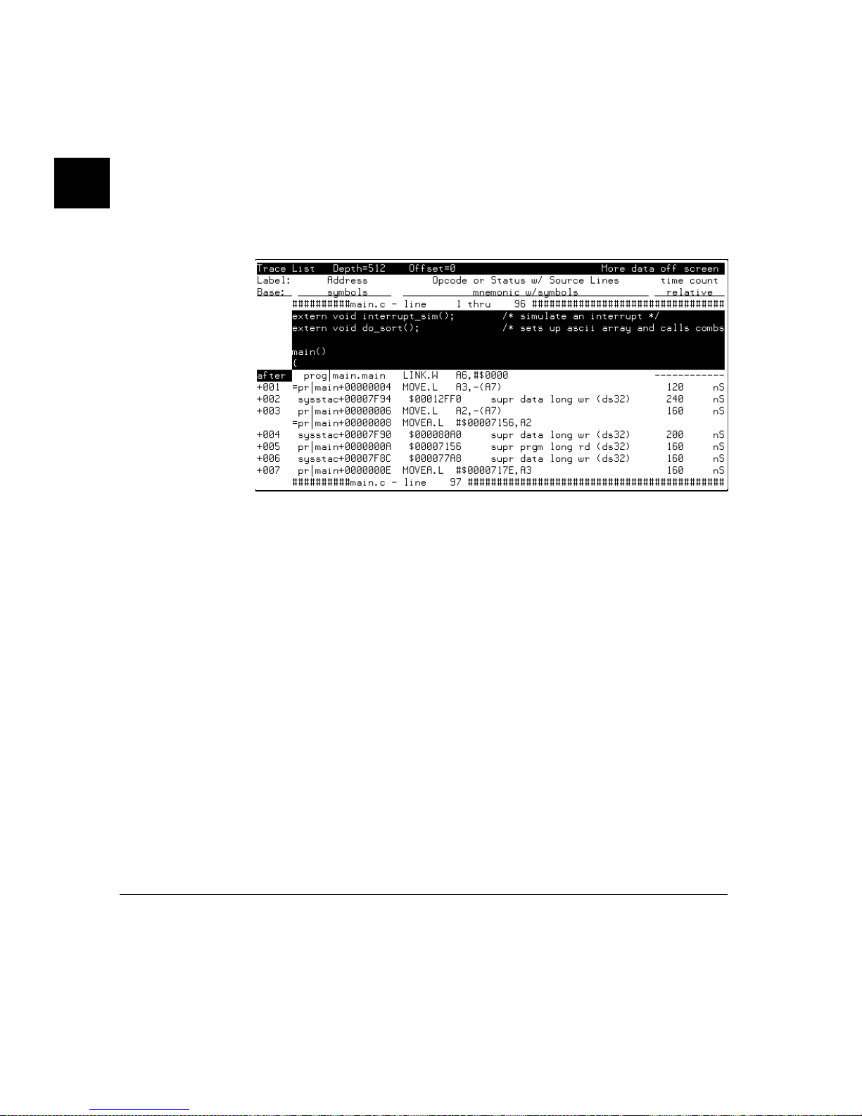
Displaying the Trace List 186
To disassembl e the trace list 189
To specify trace disa ssem bl y opt io ns 190
To specify tra ce deq ueu ei ng opt io ns 192
To display the tra ce without disa ssembly 194
To display symbol s in the trace list 195
To display source lines in the trace list 197
To change the column wi dth 198
To select the ty pe of count in form a tion in the trace list 199
To offset addresses i n the trace list 201
To reset the trace di spl ay de fa ult s 202
To move through the trace list 202
To display the trace list ar ound a specif ic line num be r 203
To change the number of states availab le for di splay 204
To display program memory assoc iated wit h a trace list line 205
To open an edit window into the source file associat ed with a trace list line 205
Contents
xiii
Page 14

Contents
Making Complex Trace Measurements 206
To use address, data, and status va lue s in trace expre ssio ns 210
To enter a range in a trace expression 211
To use the sequencer 212
To specify a restart term 213
To specify trace windowing 214
To specify both sequ enc in g and windo wing 215
To count st at es or t im e 216
To define a storage qualifi er 217
To define a prestore qu alifi er 218
To trace activity leading up to a program halt 219
To modif y the trace spec if ic at ion 220
To repeat the previ ous tr ac e comma nd 221
To capture a continuous st rea m of program executi on no matter how large yo ur
program 222
Saving and Restoring Trace Data and Specifications 225
To store a trace specification 225
To store trace data 226
To load a trace specification 227
To load tr ac e da ta 228
xiv
8 Making Software Performance Measuremen ts
Activity Performance Measurements 231
To set up the trace comm an d for act ivity measurements 233
To initialize activi ty perf orm an ce measur em ents 234
To interpre t activi ty mea sure m ent report s 238
Duration Performance Measurements 246
To set up the tra ce comm an d for du ration measu rements 247
To initial iz e duration performance measu rem e nts 249
To interpret dur ation measur em en t report s 251
Running Measurements and Creating Reports 255
To run perform ance mea sure m ents 255
To end perform an ce measur em en ts 256
To create a perform ance measur emen t report 257
Page 15

9 Making Coordinated Measurements
Setting Up for Coordinated Measurements 263
To connect the Coordi na ted Mea sure me nt Bus (CMB) 263
To connect to the rear panel BNC 265
Starting/Stopping Multiple Emulators 267
To enable synchronous m easure m ent s 267
To start synchronou s me asur emen ts 268
To disable synchro nous m easure m ents 268
Using Trigger Signals 269
To drive the emulation analyzer trigger signal to the CMB 272
To drive t he e mu la ti on analyze r tr igger signal to the BNC connecto r 272
To break emula tor execut io n on sig nal from CMB 273
To break emula tor execut io n on sig nal from BNC 273
To arm the emulatio n analy zer on sig nal from CMB 274
To arm the emulatio n analy zer on sig nal from BNC 274
Contents
xv
Page 16

Contents
Part 3 Reference
10 Setting X Resources
To modify Graphic al User Inte rfa ce resou rce s 280
To use customize d schem e files 284
To set up custom acti on ke ys 286
To set initial recall buf fer values 287
To set up demos or tutorials 289
11 Emulator/Analyzer Interface Commands
How Pulldown Menu s Map to the Comma nd Lin e 294
How Pop-up Menus Map t o the Comm and Line 299
Syntax Conventions 301
Commands 302
break 303
bbaunld 304
cmb_execute 305
copy 306
copy local_symbols_in 309
copy memory 310
copy registers 312
copy trace 313
display 314
display co nfi gura ti on_ inf o 316
display data 319
display global_symbols 322
display local_symbols_in 323
display memory 324
display registers 328
display simulated_io 329
display softwar e_b rea kpo int s 330
display tr ace 331
end 335
--EXPR-- 336
FCODE 339
forward 341
help 342
load 344
xvi
Page 17

log_commands 346
modify 347
modify configuration 348
modify keyboard_to_simio 349
modify memory 350
modify register 353
modify softwar e_b rea kpo int s 354
performance_measurement_end 356
performance_measurement_initialize 357
performance_measurement_run 359
pod_command 360
QUALIFIER 362
RANGE 364
reset 366
run 367
SEQUENCING 369
set 371
specify 376
STATE 378
step 380
stop_trace 382
store 383
--SYMB-- 385
sync_sim_registers 392
trace 393
TRIGGER 396
wait 398
WINDOW 400
Contents
12 Emulator Error Messages
Emulator error messages 404
xvii
Page 18

Contents
Part 4 Concept Guide
13 Concepts of the EMSIM and EMRAM
Concepts of the EMSIM and EMRAM 445
Concepts of the EMRAM 447
Concepts of Show Cyc le s 447
EMSIM/EMRAM Utility Command 448
xviii
Page 19

Part 5 Installation and Service Guide
14 Installation
Connecting the HP 64700 to a Computer or LAN 456
Installing HP 9000 Software 457
Step 1. Install the softwar e from the med ia 457
Step 2. Verify t he sof twa re i nsta ll ation 459
Step 3a. Start the X serve r and the Moti f Wind ow Mana ge r (m wm) 460
Step 3b. Start HP VUE 460
Step 4. Set the necessa ry en vir onm en t varia bl es 461
Installing Sun SPARCsystem Software 463
Step 1. Install the softwar e from the med ia 463
Step 2. Start the X server and OpenW in dows 464
Step 3. Set the necessa ry en vir onm en t varia bl es 464
Step 4. Verify t he sof twa re i nsta ll ation 466
Step 5. Map your fun ction keys 467
Contents
Verifying the Installation 468
Step 1. Determ i ne t he logical name of you r em ul at or 468
Step 2. Start the i nterface with the em ul700 comm and 469
Step 3. Exit the Graphical User Interface 472
15 Installing/Updating Emulator Firmware
To update emulat or fi rm ware with "prog fla sh" 475
To display curren t firm ware ver sion inform at ion 478
If there is a power failur e dur ing a firmwa re upda te 479
Glossary
Index
xix
Page 20

xx
Page 21

Part 1
Quick Start Guide
1
Page 22

Part 1
Quick Start Guide
In This Part
This part desc rib es how t o qui ckl y becom e product ive with the emul ation system.
2
Page 23

1
Getting Started
3
Page 24
Chapter 1: Getting Started
The Emulator/Analyzer Interface — At
a Glance
When an X Window Syste m that suppo rts OSF/ Moti f interfa ces is runn ing on the
host computer, the emula to r/ana lyz er int erf ace is the Graphi ca l User Int erf ace
which provides pu ll -down and pop-up menus, point and click set ting of
breakpoi nts, cut an d paste, on-li ne help , custo mi za bl e action ke ys an d pop- up re call
buffers, etc .
The emulator /anal yz er interfa ce can also be the Softke y Int erfac e which is provide d
for several typ es of t ermi nal s, termi na l emul ators, and bitmapp ed displ ays. When
using the Softkey Int erf ac e, comm an ds are enter ed from the keyb oar d.
The Softkey Interface
Display area .
Status line.
Command line .
4
Display area. Can show mem ory, data values, analyzer tr aces, registers,
breakpoi nts, sta tu s, simulate d I/O, global symbols, loc al symbols, pod com mands
(the emulator ’s unde rl ying Terminal Interface), error lo g, or displa y log . You can
use the UP ARROW, DOWN ARROW, PAGE UP, and PAGE DOWN cu rsor key s
to scroll or page up or down the inf orm atio n in the active wind ow.
Page 25

Chapter 1: Getting Started
Status line. Displa ys th e emulat or a nd an alyze r sta tu s. Al so, when error and
status message s occ ur, th ey are displ aye d on the status li ne in add ition to being
saved i n the err or lo g.
Command line. Commands are enter ed on the comm and line by pressi ng
softkeys (or by typing t hem in) and execut ed by pressing the Return key. The Tab
and Shift-Tab key s allow you to move the cursor on the comm and line forwa rd or
backward. The Clear line key (or CTRL- e) cle ars fr om the cursor posi tion to the
end of the line . The CT RL -u key clears the w ho le com m and lin e.
Softkey Interface Conventions
Example Softkey Int erfac e comma nds t hrou ghou t the manu al use the follo wing
conventions:
bold Commands, options, and par ts of c om mand syntax.
bold italic
normal User specified parts of a comma nd.
$ Represents the UNIX prompt . Commands whi ch foll ow
<RETURN> The carr ia ge re turn key.
Commands, options, and par ts of c om mand syntax which
may be entered by pressing softkeys.
the "$" are entered at the UNIX prompt.
5
Page 26
Chapter 1: Getting Started
The Graphical User Interface
Menu ba r
Action ke ys
Entry buffer
Entry buffer recall
button.
Display area .
Scroll bar.
Status line.
Command line .
Command li n e entr y
area.
Softkey pushbuttons
6
Command but tons. Include s com m and
recall button.
Cursor buttons for comm and line area
control .
Menu Bar. Provides pulldown me nus fr om whic h you sele ct comm and s. When
menu items are not applicable, th ey appe ar ha lf -bri ght and do not respo nd to mouse
clicks.
Action Keys. User-defined pushbu ttons. You can label these pu shbut to ns and
define th e ac ti on t o be pe rf o rmed.
Page 27

Chapter 1: Getting Started
Entry Buffer. Wherever you see "()" in a pulldo wn me nu, th e conte nt s of the
entry buffe r ar e use d in that com m an d. You can type val ue s int o the ent ry bu ffer,
or you can cut and past e values into th e entry buffer from the di spl ay a rea or fro m
the command li ne ent ry ar ea. You can also se t up act ion keys t o use the contents of
the entry buffe r.
Entry Buffer Recall Button . Allows you to recall entry bu ffe r val ue s tha t have
been predefined or used in previ ous comm ands. When you click on the entry
buffer Recall button, a dialog box appea rs tha t allows you t o sel ect va lues .
Display Area. Can show mem ory, data values, analyzer tr ac es, regist ers,
breakpoi nts, sta tu s, simulate d I/O, global symbols, loc al symbols, pod com mands
(the emula tor ’s unde rl yin g Te rm in al Inte rfa ce ), error lo g, or disp lay log .
Whenever the mouse poin te r change s from an arro w to a hand, you can press and
hold the sel ect m ouse button to access pop- up m enu s.
Scroll Bar. A "sticky slider" that al lows na vi gation in the display area. Click on
the upper and lower a rrows t o scroll to the top (hom e) and bott om (end) of t he
window. Click on the inner ar rows to scrol l on e line. Drag the sli der handle up or
down to cause continuous sc rol li ng. Click betwe en the inner arrows an d the sli der
handle to page up or page down.
Status Line. Displays the emulator and analyz er stat us. Also, when error and
status message s occ ur, th ey are displ aye d on the status li ne in add ition to being
saved in the error lo g. You can press and hold th e sel ec t m ouse button to ac ce s s
the Status Line pop-up menu.
Command Lin e. The command line area is similar to the command line in the
Softkey Interf ac e; howev er, th e graphi ca l interfa ce lets you use the mouse to enter
and edit commands.
• Command line entr y area. Allows you to enter com ma nds fr om the
command line.
• Softkey pushbuttons. Clicking on t hese pushbutt ons, or pr essi ng soft ke ys,
places the com mand i n the comm an d line entr y area. You can press and hold
the select mouse butto n to access the Com m and Line pop-u p menu.
• Command buttons (includes command recall button). The command Return
button is the same as pressin g the carri age return key — it sends the comm and
in the com m an d li ne e ntr y area to the em ul at or/analy ze r.
7
Page 28

Chapter 1: Getting Started
• Cursor buttons for command line area control. Allow you to move the
You can choose not to displa y th e comm and li ne area by turni ng i t off . For the
most commo n emul ator/ ana ly zer ope ratio ns, the pulldown menus, pop- up menu s,
and action keys prov ide all the contr ol yo u need. Choosing men u item s that requi re
use of the comm an d li ne wi ll aut om at ic ally t urn t he com ma nd l ine bac k on.
Graphical User Interface Conventions
Choosing Menu Commands
This chapte r uses a short hand notation for indic at in g that you shoul d ch oose a
particula r menu item. For example, the following instruction
Choose File→Load→Configur ation
The com ma nd R e cal l butt on allo ws y ou to recall pre vi ous or pr ede fi ned
commands. When you click on the command Recall but ton , a dia log box
appears that allows you to selec t a command .
cursor in the command line entry area forward or back ward , clear to the end of
the command line, or clear the whole command line entry area.
means to first display the File pulldown menu, then displa y the Loa d cascade
menu, then select the Configuration item from the Lo ad c asc ade menu.
Based on thi s expl an at ion , the ge ne ral rul e for interpretin g thi s not at ion can be
stated as follows:
• The leftmost i te m in bol d is th e pulld own m enu lab el.
• If there are more tha n two ite ms, th en casc ade menus a re involved and all
items be tween the first and last item have cascade menus attached.
• The last item on the right is the actual menu choice to be made.
8
Page 29

Chapter 1: Getting Started
Mouse Button and Keyboard Bindin gs
Because the Gra phi ca l Use r Int erf ac e runs on dif fer ent kinds of comp uters, which
may have differe nt convent io ns for m ouse but ton s and ke y name s, the Graphical
User Interface supports di fferent bindi ngs and th e cu stom i zati on of bi ndi ngs.
This manual ref ers t o the mo use bu tt ons usi ng ge ner al (or "ge ner ic ") term s. The
following table desc rib es th e gener ic mou se butto n name s and sho ws the defaul t
mouse button bindings.
Mouse Button Bindings and Description
Bindings:
Generic
Button
Name
HP 9000
Sun
SPARCsystem
Description
paste left left Paste from the display
area to the entry buffer.
command paste middle
1
middle
1
Paste from the ent ry
buffe r to t he c om mand
line text entr y area.
select right right Cl ic k sel ects first item in
pop-up menus. Press and
hold displays m en us.
command select left ri ght Displays pul ld own menus.
pushbutton
select
left left Actuates pushbuttons
outside of the displ ay
area.
1
Middle button on three-b utt on mouse. Both buttons on two-butt on mouse .
9
Page 30

Chapter 1: Getting Started
The following table s show th e defau lt keyboar d bin din gs.
Keyboard Key Bindings
Generic Key Name HP 9000 Sun SPARCsystem
menu sel ec t extend cha r extend char
insert insert char insert char
delete delet e ch ar delete cha r
left-arrow left arrow left arrow
right-arrow right arrow right arrow
up-arrow up arrow up arrow
down-arrow down arrow down arrow
escape escape escape
TAB TAB TAB
10
Page 31

Chapter 1: Getting Started
The Getting Started Tutorial
This tutoria l give s you ste p-by-step instr uct io ns on how to per form a few basi c
tasks using the emulat or/ an alyze r inte rfa ce. The tuto rial exam pl es presented in this
chapter make the following assum ptio ns:
• The HP 64780 emul at or a nd 80- channel anal yz er a re insta ll ed int o the
HP 64700 Card Cage, the HP 64700 is conne cted to the host comput er , and the
Graphical Use r Interf ac e softwar e has bee n instal led as ou tl ined in Chapte r 14,
"Install ation."
• The emulator is ope rat in g out-of- ci rcu it (that is, pl ugg ed into the demo boa rd,
not your target system).
• You have select ed the appropri at e cloc k modul e and in sta ll ed it in the
emulator probe according to the instruct io ns in the MC68360
Emulator/Analyzer (HP 64780A) In sta ll ation/Service /Ter mi na l Inter face
manual that was suppl ie d wit h your emula to r hardware.
The Demonstratio n Progr am
The demonstrat io n program use d in this chap te r is a simple environ me nt al cont rol
system. The program con tro ls th e temper at ure and humi dity of a room requi rin g
accurat e envi ronm e ntal control .
Depending of the ver sion of the demo pr ogra m you are usi ng an d of your com pi ler,
line numbers and memory locatio ns ma y not matc h th ose sh o wn in this m an ual.
11
Page 32

Chapter 1: Getting Started
Step 1. Start the demo
Step 1. Start the demo
A demo program and its associ ated file s are prov ided wit h the Graphi ca l User
Interface.
1 Change to the dem o dir ec tor y.
$ cd /usr/hp64000/demo/debug_env/hp64780 <RETURN>
Refer to the README file for more informati on on the demo program .
2 Check that "/usr/hp640 00/ bin " and "." are in your PATH envi ron ment variab le. To
see the value of PATH:
$ echo $PATH <RETURN>
3 If the Graphical User Int erf ace soft war e is insta ll ed on a different type of computer
than the computer yo u are using, edit the "pl atform Sc hem e " resou rce set ting in the
"Xdefault s.e m ul" fi le.
12
For example, if the Graphical User Inter face wi ll be run on a HP 9000 comput er
and displayed on a Sun SPARCsystem comput er , change the platfor m scheme to
"SunOS".
4 Start the emulator/analyzer demo.
$ Startemul <logical_emul_name> <RETURN>
This scrip t sta rt s the emula tor/ana lyz er interfac e (with a customized set of act ion
keys), loads a confi gur ation fil e for the demo pro gra m, an d then loads t he dem o
program.
The <log ic al _em ul _name> in th e co mm a nd ab ove is the logic al emulator nam e
given in the HP 64700 emulator devic e table file (/usr/h p640 00/ et c/6470 0ta b.ne t).
Page 33

Chapter 1: Getting Started
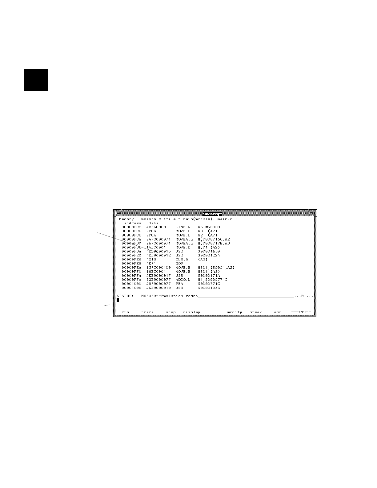
Step 2: Display the pro gram in memo ry
Step 2: Display the program in memory
1 If the symbol "main" is not already i n the entry bu ffe r, move the mouse poin te r to
the entry buffer (no tice the flashin g I-be am cu rsor) and type in "main".
2 Choose Display→ Memory→M ne moni c ().
Or, using the com m and line, enter:
display memory
main
mnemonic
<RETURN>
The default display mo de setting s cau se source lines and sym bol s to appear in
displays whe re appro pri ate. Notice you can use symb ols whe n spe cifyi ng
expression s. The globa l symbo l "mai n" is use d in the com mand a bove to specify
the starting address of the mem or y to be disp layed .
13
Page 34
Chapter 1: Getting Started
Step 3: Run from the transfer address
Step 3: Run from the trans fer addre ss
The transfer address is t he entr y add ress defi ned by the soft ware dev elopm en t tools
and included with the progr am’s sym bol informat ion.
• Click on th e Run Xfer til () acti on key.
Or, using the com m and line, enter:
run from transfer_address until
Notice the message "Softwa re brea k: <add ress> " is displa ye d on the statu s line and
that the emulator is "Run nin g in moni tor" (you may have to click the select mouse
button to remove temporary messag es fro m the status line) . When you run until an
address, a breakpoint is set at the address before the prog ram is run.
main <RETURN>
Notice the highligh te d bar on the screen ; it shows the curre nt pr ogra m coun ter.
14
Page 35
Chapter 1: Getting Started
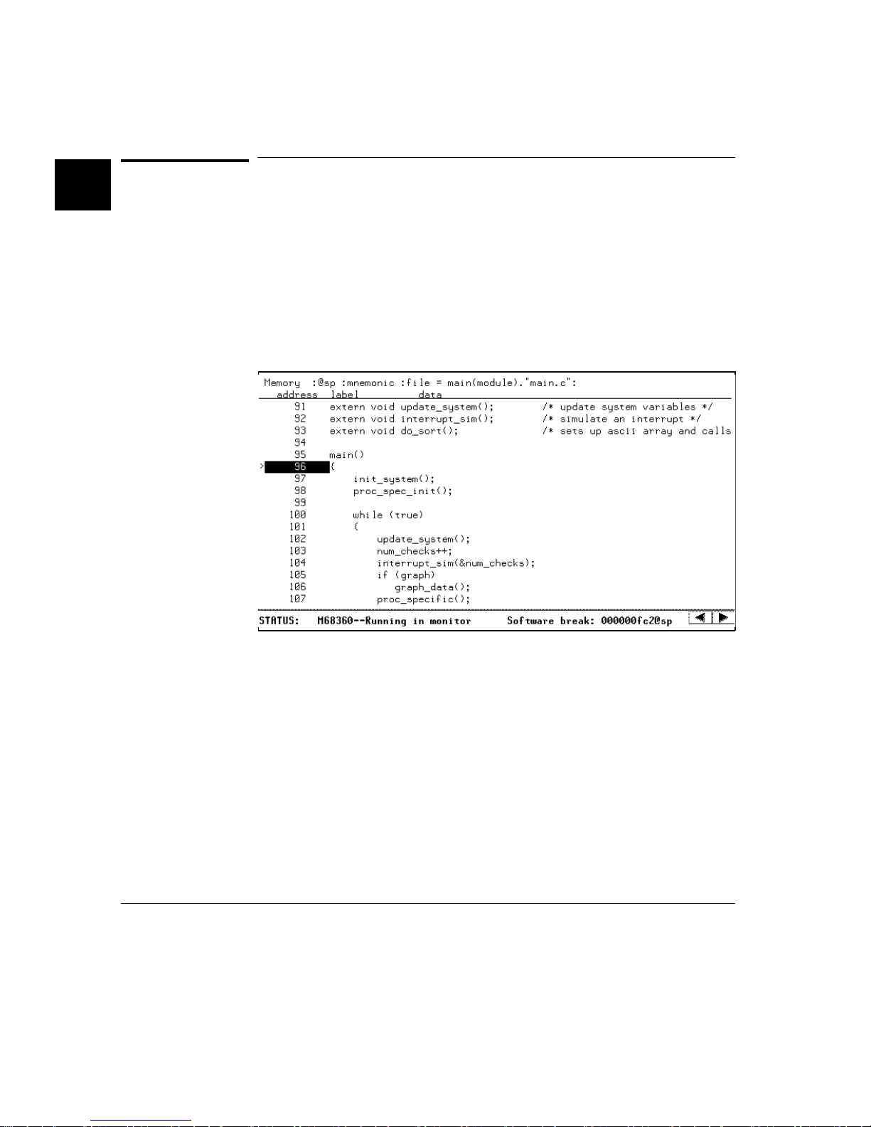
Step 4: Step high-l evel so urce lin es
Step 4: Step high-level source lines
You can step through the progra m by high -leve l source lines. The emulat or
executes as many instruc ti ons as are associ at ed with the high -le ve l progra m source
lines.
1 To step a source line from the current progr am cou nte r, click on the Step Source
action ke y.
Or, using the com m and line, enter:
step source
Notice that the high li ght ed bar (t he curre nt progr am cou nte r) m ove s to the next
high-level source line.
2 Step into the "init_syst em " fun ction by con tinuing to step sourc e line s, eit her by
clicki ng on t he Ste p Sourc e action key, by clicking on the Again action key which
repeats the pr evi ous c om mand, or by entering t he ste p sourc e command on the
comm and li ne.
<RETURN>
15
Page 36

Chapter 1: Getting Started
Step 5: Display the previous mnemonic display
Step 5: D isp la y th e pre vio u s mne m o ni c dis p lay
• Click on th e Disp Sr c Prev action ke y.
Or, using the com m and line, enter:
display memory mnemonic previous_display
This comma nd is u sefu l, for exam pl e, when you ha ve step ped into a funct ion that
you do not wish to look at—you can display the previous mnemonic display and
run until the source line that follows t he functio n call .
<RETURN>
16
Page 37
Chapter 1: Getting Started
Step 6: Run until an address
Step 6: Run until an address
When displaying memo ry in mne monic format, a sele ction in the pop-up men u lets
you run from the current progr am counte r addre ss unti l a specifi c source line.
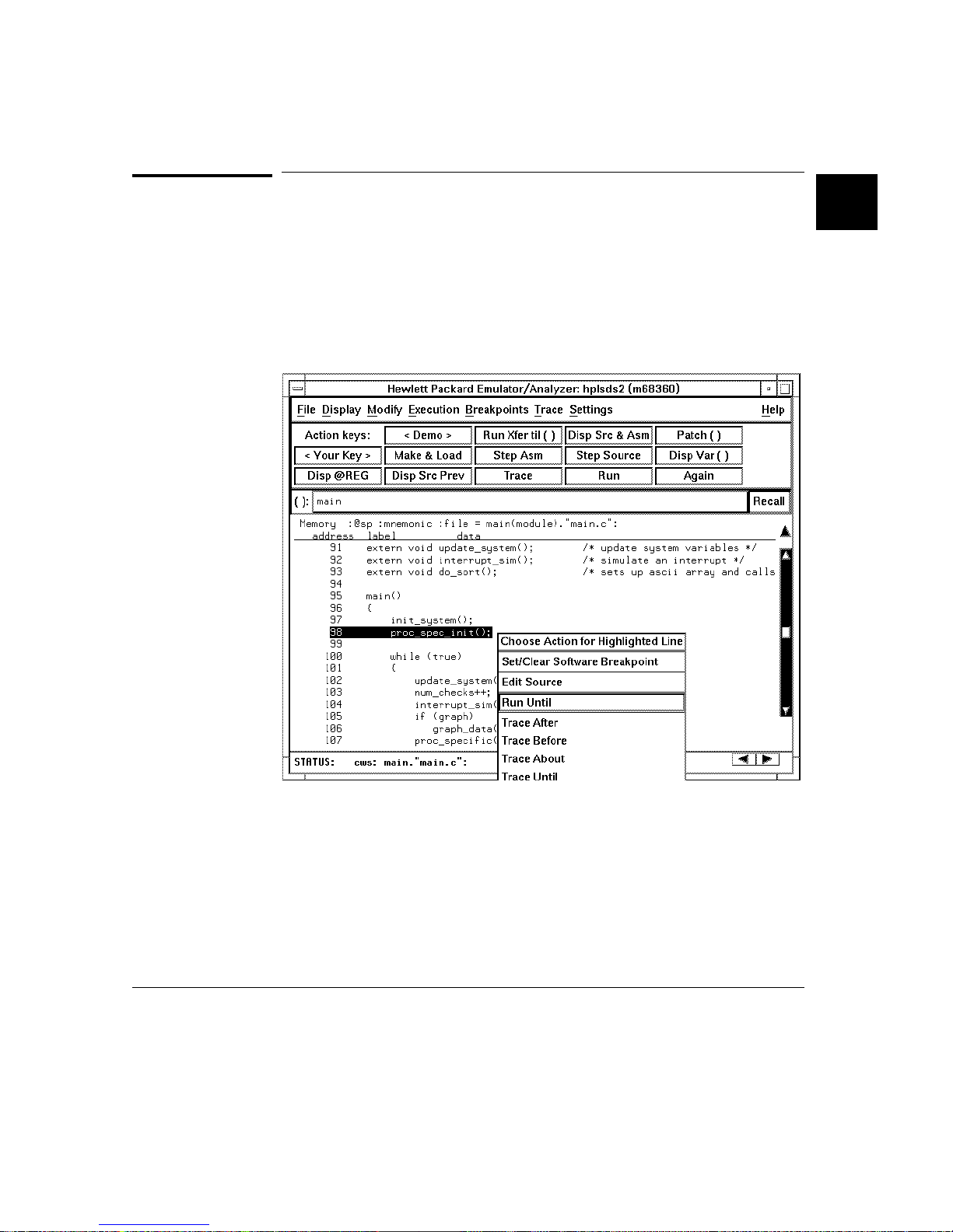
• Position the mouse poin ter ove r the line "pr oc_ spec _i nit(); ", press a nd hold th e
select mouse button, and choose Run Until from the pop-up menu.
Or, using the com m and line, enter:
run until
After the command ha s execu ted, notice the hig hlight ed bar indi cate s the progr am
counter has moved to the specified source line.
main."main.c": line 98 <RETURN>
17
Page 38
Chapter 1: Getting Started
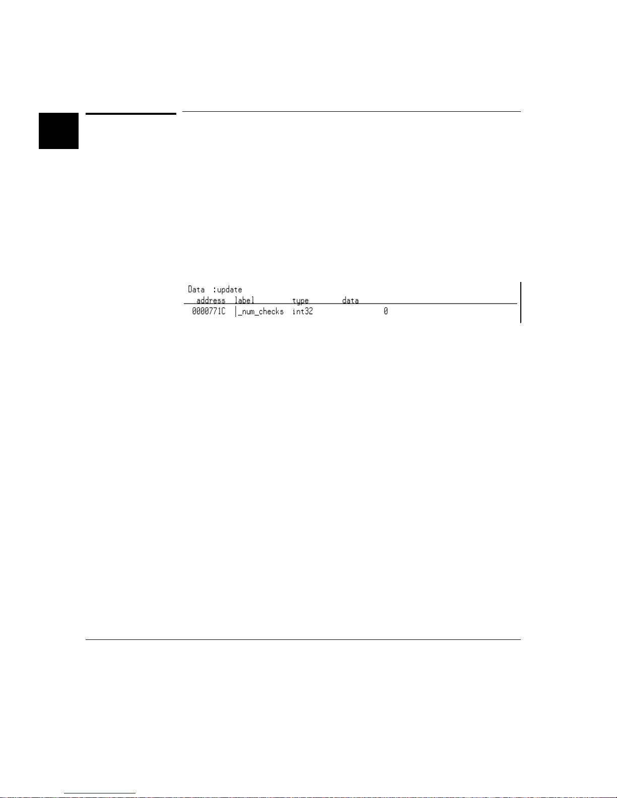
Step 7: Display data values
Step 7: Display data values
1 Position the mouse pointer ove r "num_c hec ks" in the sourc e line that reads
"num_checks++;" and click the paste mo use bu tton (notice "num_checks" is cut
and pasted int o the ent ry bu ffe r).
2 Click on the Disp Var () ac tion key.
Or, using the com m and line, enter:
display data ,
The "num_ che ck s" v ari ab le is add ed t o the data va lu es display an d its v al ue is
displaye d as a 32 -bi t inte ger .
num_checks
int32
<RETURN>
18
Page 39
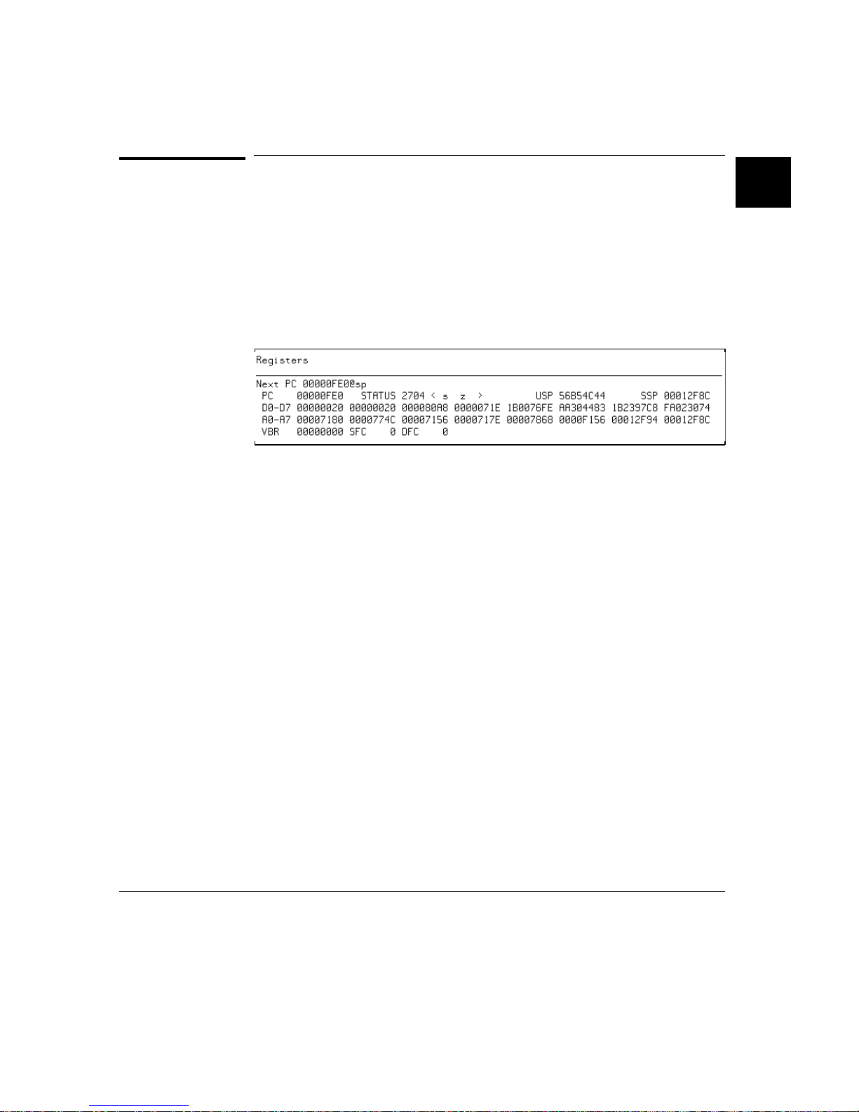
Step 8: Display registers
You can display the cont ents of th e proce ssor re gist er s.
• Choose Display → Regi ste rs→BASIC.
Or, using the com m and line, enter:
Chapter 1: Getting Started
Step 8: Display registers
display registers
<RETURN>
19
Page 40
Chapter 1: Getting Started
Step 9: Step assemb ly- level instruction s
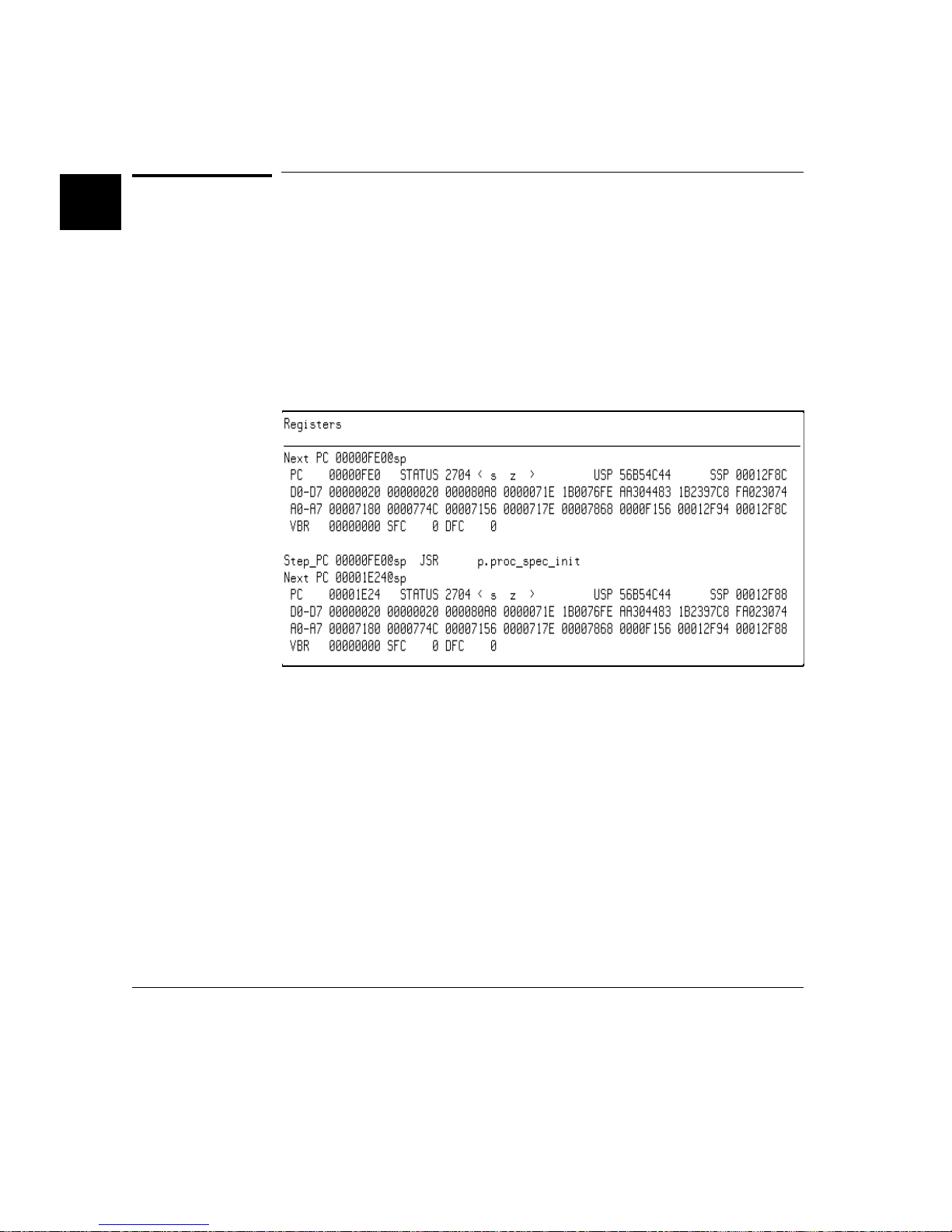
Step 9: Step assembly-level instructions
You can step through the progra m one instru ct ion at a time.
• To step one inst ruc tion from the current program cou nter, clic k on the Step Asm
action key.
Or, using the com m and line, enter:
step
<RETURN>
20
Notice, when registe rs ar e displa ye d, step pin g causes t he assem bl y langua ge
instruction just executed to be displayed.
Page 41

Chapter 1: Getting Started
Step 10: Trace the progra m
Step 10: Trace the pr ogram
When the analyzer traces program execution, it looks at the data on the emulation
processor’s bus and cont rol signa ls at each clock cycle. The infor mati on seen at a
particular clock cycle is called a state.
When one of these states matches the "trigger state" you specify, the analyzer
stores stat es in tra ce memory. When tr ace m emory is filled, the tra ce is sai d to be
"com ple te."
1 Click on th e Rec al l but to n to the ri ght of th e en try buffe r.
A selection di al og box appe ar s. You can sele ct from ent ry bu ffe r val ue s tha t have
been entered pre vio usly or that have bee n predefined.
2 Click on "main" in the selection dialog box, and click the "OK" pushbut to n.
Notice that the value "main" has been returned to the entry buffer.
3 To trigger on the address "ma in " and st ore stat es t hat occur a fte r th e trigg er, choose
Trace→ Afte r () .
Or, using the com m and line, enter:
trace after
Notice the messa ge "Em ula tion t rac e start ed " appe ar s on the sta tus line . This
shows that the analyze r has be gun to look for the trigge r sta te which is th e addre s s
"main" on the proce ssor’s address bus.
4 Run the emulator demo progra m from its tra nsfe r address by choo sing
Execution→Run→f rom Transfer Address.
Or, using the com m and line, enter:
run from transfer_address
Notice that now the message on the status li ne is "Emul at ion trace complet e". This
shows the trigger state ha s been fou nd an d the ana lyze r trace mem ory ha s been
fill ed.
main <RETURN>
<RETURN>
21
Page 42
Chapter 1: Getting Started
Step 10: Trace the pro gram
5 To view the captured states, ch oose Displa y→ Tr ace.
Or, using the com m and line, enter:
display trace
<RETURN>
The default display mo de setting s cau se source lines and sym bol s to appear in the
trace list.
Captured states are numbered in the left-hand column of the trace list. Line 0
always cont ai ns th e state tha t cause d th e an al yze r to trigger.
Other columns cont ai n address in fo rmation , data val ues, opcod e or st at u s
information, and time count information.
22
Page 43

Chapter 1: Getting Started
Step 11: Display memory at an address in a regist e r
Step 11: Display memory at an address in a
register
1 Click on the Disp @RE G a ct ion key.
Or, using the com m and line, enter the nam e of the command fil e:
mematreg <RETURN>
A comman d fil e di al og bo x app ea rs (or a prom pt appe ar s in th e co mm a nd li ne ).
2 Move the mouse pointer to the dialog box text entry area, type "A7", and click on
the "OK" but ton .
Or, if the p r ompt is in th e co mmand li ne:
A7 <RETURN>
23
Page 44

Chapter 1: Getting Started
Step 12: Exit the emulator/analyzer interface
Step 12: Exit the emulator/analy zer i nterface
• To exit the emula tor /anal yz er interface and release the emul ator, choose
File→Exit→Release d .
Or, using the com m and line, enter:
end release_system
<RETURN>
Solving Problems
If you encounter proble ms when usi ng the emulat or/ an alyze r, ref er to the chapter
titled "Solving Pro blem s" in the MC68360 E m ulato r/An al yzer
Installation/Service/Terminal Int erface Manual.
24
Page 45

Part 2
Using The Emulat or
25
Page 46

Part 2
Making Measurements
When you’ve becom e fam ilia r with th e basic emulati on pr oce ss, you’l l want to
make specific measur em en ts to analyze yo ur softwar e and targe t system . The
emulator has many feat ure s that allow you to con tro l pro gra m execution , view
processor resources, and prog ram activi ty.
In This Part 2
Chapter 2, "Pluggi ng in to a Targe t System ," tells yo u how to corr ectl y connec t the
emulation probe into a target system .
Chapter 3, "Start ing and exitin g HP 64700 Interfa ce s, " tells yo u how to get the
desired in te rfa ce on screen.
Chapter 4, “Enter ing Com mands, ” tells yo u how to use th e comma nds an d featu res
of the Graphical User Int erf ace an d Softkey Inte rfa ce.
Chapter 5, “Confi guring the Emul ator, ” explains how to use the emul at or/ an al yzer
commands to alloc ate emulat ion reso urc es suc h as memory and how to enable and
disable certain emul at or fe at ure s.
26
Chapter 6, “Using the Em ulato r,” shows yo u how to use the emulat or/ anal yzer
commands to cont rol the emul ation processor and mak e simpl e emu lati on
measurement s.
Chapter 7, “Using t he Em ulati on- Bus Ana lyz er,” expla ins ho w to use the
emulatio n-bu s ana lyzer to recor d prog ram exec ution for debugging.
Chapter 8, "Making Softwa re Perfo rm anc e Measur em ents," shows you how to use
the Software Perform a nce Mea sure ment Tool suppli ed with the emu lator .
Chapter 9, “Making Coordi nat ed Measurements,” tells ho w to co upl e two or mo re
emulators to coo rdi nat e measure m ents involving more than one pro cessor.
This part of the manua l expl ains how to accom pl ish va rious co mm on tasks, of ten
requirin g use of several emul at or/ ana ly zer comm an ds tog et her . It assum e s you
know how to use the comm an ds to c ont rol the emula tor. If you need a general
introduction to using the emulator, refer to Part 1.
Page 47

2
Plugging into a Tar get System
27
Page 48

Plugging the Emulator into a Target
System
This chapte r desc ri bes the t asks yo u must pe rfor m whe n plugging the emula tor into
a target system. These tasks are group ed into the foll owi ng sec tions:
• Connecting the emulator to the target system.
• Plugging into the Motorola QUADS target syste m.
Before attemp ti ng to run the emul at or, ensure that you have selec ted the prop er
clock modul e and inst al le d it in the emu la tor probe . The detai ls of cloc k m odul e
selection are discussed in the MC68360 E mula tor /Ana ly ze r (HP 64789A)
Installation/Service/ Terminal Interface manual.
28
Page 49
Chapter 2: Plugging into a Target System
Connectin g the Emulat or to the Target Syste m
Connecting the Emulator to the Target
System
The 68360 emula tor probe plugs int o a PGA throug h-ho le socke t that is sol der ed
into the target syste m. There are thr ee ways of c onne ct in g the 6836 0 emul ator
probe to a target system:
• Plug it into the PGA socket directly.
• Plug it into the PGA socket via flexible cable.
• Plug in a PQFP adapter socket into the PGA socket in place of the emulator,
and then connect the emulator probe to the PQFP adapte r.
29
Page 50

Chapter 2: Plugging into a Target System
Connecting the Emul ato r to the Target System
If using a PQFP adapte r, the emula to r wil l trist at e your targe t 683 60 an d use the
emulator’s 6 8360 to run your targ et syste m.
This section desc ribes the steps you must per form when con necting the emu la tor to
a target system:
1 Turn OFF power.
2 Plug the emulator probe into the target system .
3 Turn ON power.
CAUTION Possibl e Damage to the Emulator Probe . The e mu la tor cont ai ns de vic es t hat are
susceptible to damage by static discharge. Theref ore , precaut io nar y measu res
should be taken before handling the emulat or probe to avoid dam aging the interna l
compone nts of the emula to r by sta ti c ele ct ric it y.
Step 1. Turn OFF power
CAUTION Possibl e Damage to the Emulator . Make sure target system power is OFF and
make sure HP 64700 po wer is OFF befor e removing or installing the emulato r
probe into the target system.
Do not turn HP 64700 power OFF whil e the em ulat or is plugge d into a target
system whose power is O N.
1 If the emulator is currently plugged into a different target system, turn th at target syste m’s powe r OFF.
2 Turn emula tor power OFF.
30
Page 51
Chapter 2: Plugging into a Target System
Connectin g the Emulat or to the Target Syste m
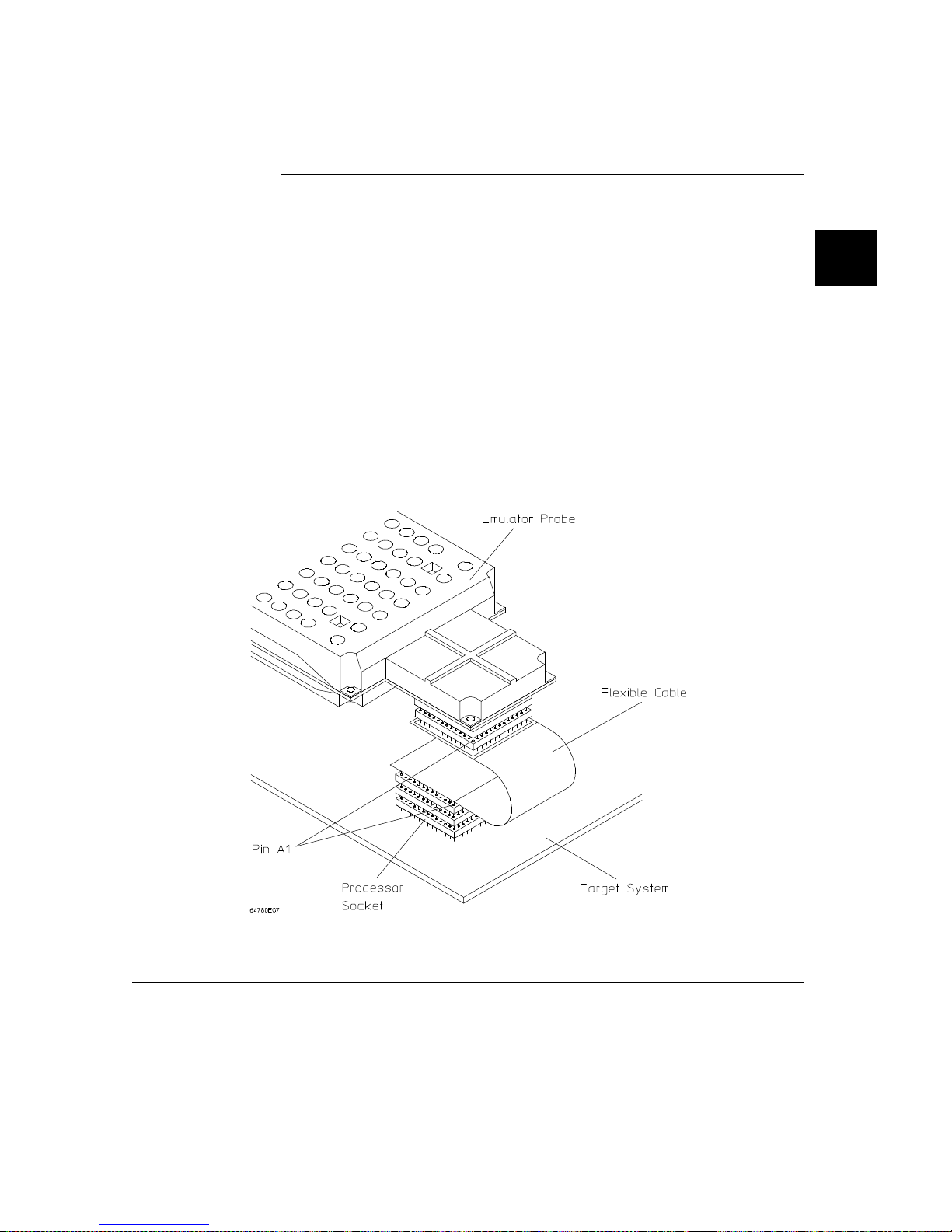
Step 2. Connect the probe to the target system
CAUTION Possibl e Damage to the Emulator Probe. A pin extender i s inc lud ed wi th the
emul ator probe. Do not use the probe without a pin exte nder installed.
Replacing a broke n pin ext en der is mu ch less ex pen sive tha n repla ci ng ot he r pie ces.
The use of more than one pin exte nde r is disco ura ged , unle ss it is necessary for
mechanical clearance reasons, because pin extenders cause signal quality
degradation.
1 Install the emulator probe into the targe t system soc ket . Make sure that pin 1 of the connector aligns
with pi n 1 of t he so c ket. Damage to the emulat or will resul t if the probe adapter is incorrectly
installed.
31
Page 52

Chapter 2: Plugging into a Target System
Connecting the Emul ato r to the Target System
Step 3. Turn ON pow er
1 Turn emulator power ON.
2 Turn target syste m po wer ON.
32
Page 53

Chapter 2: Plugging into a Target System
Plugging into the Moto rola QUADS T arget System
Plugging into the Motorola QUADS
Target System
This section shows you how to:
• Connect the emulator to the Motorol a QUADS board.
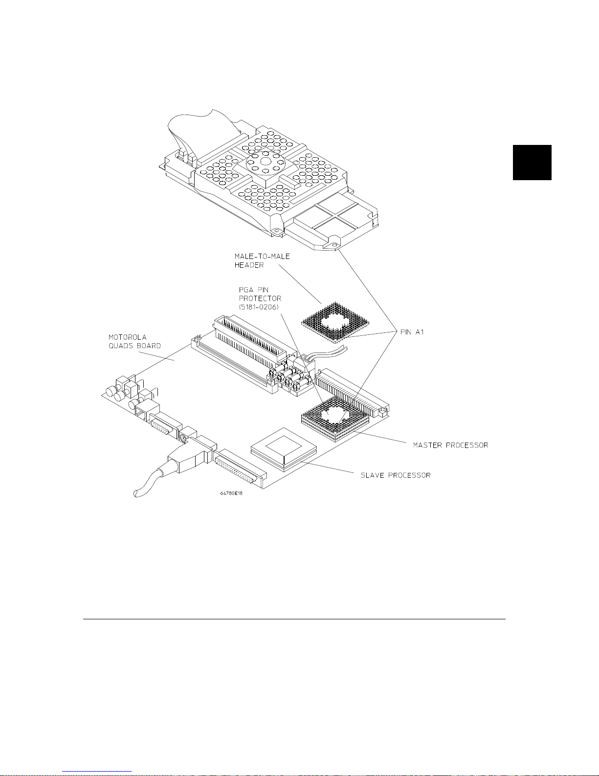
The Motorola QUADS board gives you a n oppo rtu nity to plug the emulato r into a
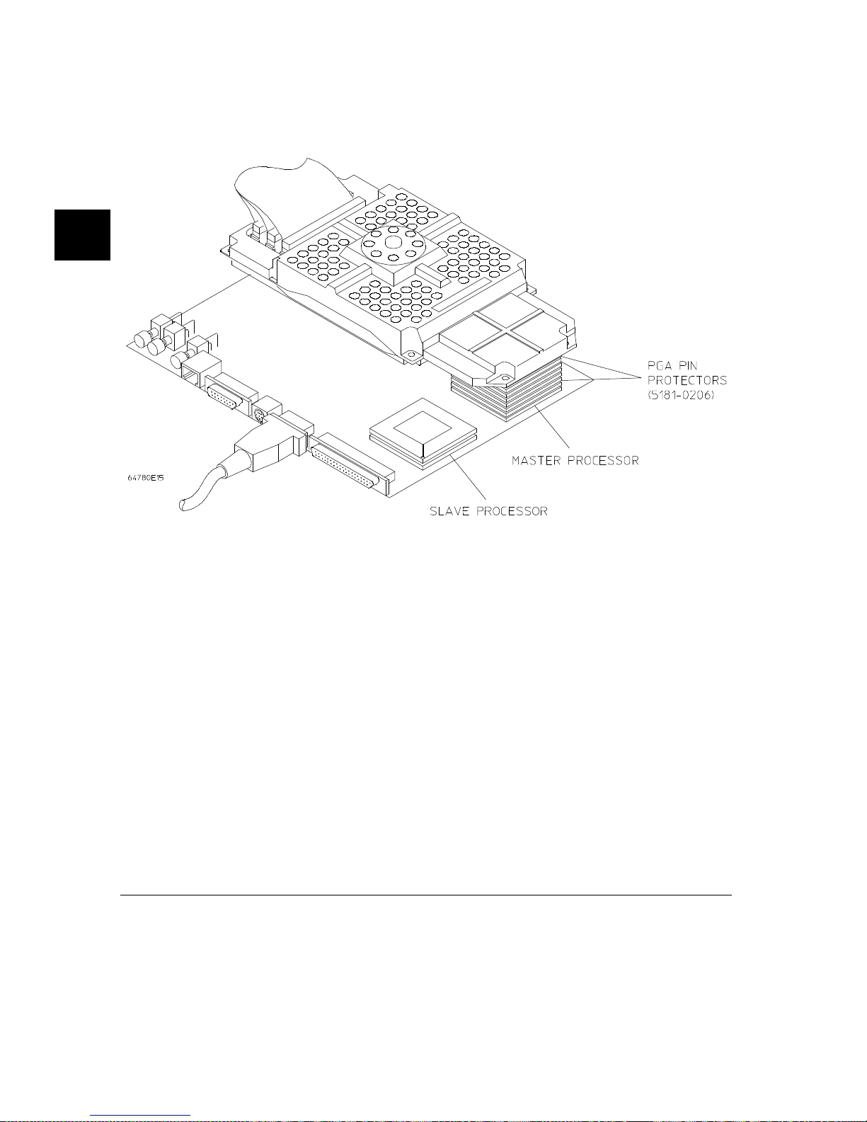
target system that contai ns one 68360 master chip, and one 68360 slave chip.
33
Page 54

Chapter 2: Plugging into a Target System
Plugging into the Motoro la QUADS Targ et System
To conn ect the emulator to the Motorola QUA DS
1 Turn OFF power.
If the emula tor is cur ren tl y plu gge d int o a diffe rent target syste m, tu rn th at target
system’s power OFF. Then, turn emulato r powe r OFF.
2 Plug the emulator probe into the Motor ola Quad s Boar d.
The emulator cont ains de vic es t hat are suscept ibl e to dama ge by static discha rge.
Take precauti ona ry m easure s before handli ng th e emulat or pr obe to avoid damag e.
The Motorola Quads bo ard contains two 68360 proc essor s: one runn ing in Master
mode, and th e ot her runni ng i n Sla ve m ode . The emulator mu st be plug ged int o the
master processor.
Make sure pin 1 of the Quads board micr opro cessor soc ket and pin 1 of the
emulator probe are properly align ed befor e inserting the probe into the socke t.
Otherwise, you may dam a ge the emu la tor cir cui tr y. Three or four pi n pro te ct ors
will be requir ed to li ft the pr obe abov e other hard ware on th e Qua ds boa rd.
34
Ensure that the defa ult clock mod ule is pl ugge d in. The defa ult clock mod ule mu st
be installed in the emu la tor probe in order for the 683 60 emul at or t o work with t he
Quads board. Refer to the Hewlett-Packard MC68360 Emulator/ A nal yze r
Installation/Service/Terminal Interface User’s Guide f or details.
Page 55
Chapter 2: Plugging into a Target System
Plugging into the Moto rola QUADS T arget System
35
Page 56
Chapter 2: Plugging into a Target System
Plugging into the Motoro la QUADS Targ et System
36
3 Turn ON power. First turn on the emul ator powe r. Then turn target system power
ON.
4 You will need to select three confi guration item s for th e emul ator. With the
Graphical User Interfa ce on scree n, choo se M odif y→ Em ulat or Config... In the
Emulator Configuration dialog box, select Emulator Pod Settings. In the Pod
Settings dial og bo x, sele ct the fol lowi ng:
• "Yes" for Buffer AS, DS and R/W.
• "Off" for Clock O1 Drive to Target .
• "8 bits" for Mem ory Si ze for Chi p Sel ect.
5 Choose Execution →Run→fro m Reset . Verify tha t the Quads board boots up
and runs normally.
Page 57

Chapter 2: Plugging into a Target System
Plugging into the Moto rola QUADS T arget System
6 Verify that the master regi ste rs disp la y norma ll y:
1 Press the "Sync $MBAR" Act ion Key. The Browser Window shoul d show
that HP64MBAR360 is synchr oni zed to 20000H.
2 Pre ss the "Pick Reg 360" Act ion Key.
3 Sel ect pepa r from the Regist er List in the Browse r Windo w and cli ck Done.
4 Pre ss the "Reg 360 ()" Act io n Key.
A Browser Window opens. It shows the contents of the master processor’s
pepar registers. Press Done when finished reviewing the register contents.
To view anothe r re gist er in the mast er re gi ste r set , simp ly re pe at step s 3 and 4
above.
7 Verify that the sla ve regi ste rs di spla y nor ma ll y:
1 Press the "Pick Util" Action Key.
2 Sel ect "assign68360chip" from the Utilitie s Sel ecti on Bro wser W in dow and
then press Done.
3 Pre ss the "Run Uti l () " Acti on Ke y to run the sel ecte d uti li ty .
4 In t he Define command fi le para m et er di al og b o x, enter 1 in the ent ry field an d
click OK. This identifies the slave chip as chip 1.
5 In the next Define com ma nd file param eter dialog box, enter 22000H and c lick
OK. This identifies the addre ss of the sla ve processor.
6 Click Done in the New Slave Addresses Br owser Window whe n you have
seen the content that identif ie s the addr esse s of the maste r and sla ve
processors.
Note that step s 1 thro ugh 6 of this proc edure only have to be done to set up th e
emulator for sla ve regi ste rs disp la ys. Once these ste ps hav e been done, you
can view any of the regist er s in th e slave chip. To switch betwee n disp laying
of master and sl ave reg ist ers, you can sim ply start with th e ne xt st ep (Step 7)
to see the slave registers or press "Syn c $MBAR" (in the previ ous pr ocedur e)
to pick the master re gist er s.
7 Press the "Pick Chip 360" Action Key.
8 From th e Available MC6 8360 Slaves Browser W in dow, select
HP64MBAR360_1 and click Done.
9 Press the "Set Ch ip ()" Action Ke y. Thi s ide nti fies the ch ip t hat wil l be
controlled and viewed in the interface.
10 The Current M68360 Browser Window should show that HP64 MBAR36 0 is
set to 22000H.
11 Press the "Pick Reg 360" Action Key.
37
Page 58

Chapter 2: Plugging into a Target System
Plugging into the Motoro la QUADS Targ et System
12 Select pepar from the Register List in the Browser Wi ndo w and cli ck Done.
13 Press the "Reg 360 ()" Action Key.
A Browser Window opens. It shows the contents of the slave processor’ s
pepar registers. Press Done when finished reviewing the register contents.
To view anothe r re gist er in the slave regi ste r set , simply repeat steps 12 an d 13
above.
38
Page 59

3
Starting and Ex iting H P 64700
Interfaces
39
Page 60

Starting and Exiting HP 64700
Interfaces
You can use several ty pes of interf ac es to the sam e emulat or a t the same time to
give yourself diffe re nt views i nto the target system .
The strength of the emul at or/analy ze r int erface is that it lets you perf orm the
real-time anal ysis mea sure m ents tha t are help ful when inte gra ting ha rdwa re and
software.
The C debugger interf ac e (which is a separate product ) lets yo u view the sta ck
backtrace and high- le vel data st ruc tur es, and it lets you use C langua ge expre ssio ns
and macros. These fe ature s are most usef ul when de bugg ing softwa re .
The Software Perfor manc e Analyz er interf ace (which is also a separate prod uct)
lets you make measurements th at can help you imp rove the perform a nce of you r
software.
These interfaces can op era te at the sam e tim e wit h th e same emulator. When you
perform an action in one of the int erf aces, it is ref lect ed in the other inte rfa ce s.
Up to 10 interface windows may be start ed fo r the same emu la tor . Only one C
debugger interfa ce window and one SPA window ar e allo wed, but you can start
multiple emulator/analyzer interface windows.
40
The tasks associated with star ting an d exiting HP 647 00 interfa ce s are group ed into
the following sectio ns:
• Starting the emulator/analyzer interface.
• Opening other HP 64700 interface windows.
• Exiting HP 64700 interf aces.
Page 61

Chapter 3: Starting and Exiting HP 64700 Interfaces
Starting the Emu lat or/An alyzer In terf ac e
Starting the Emulator/Analyzer
Interface
Before starti ng t he emu la tor /anal yz er inte rfa ce , the em ulato r and interf ac e software
must have alrea dy be en i nsta ll ed as desc ri bed in Cha pt er 14 , "Installation ".
This section desc rib es how t o:
• Star t th e inter face.
• Start the interface usi ng th e de fau lt conf igu ration.
• Run a command file on interface startup.
• Display the status of emula to rs def ined in the 64700 tab. net file.
• Unlock an interface that was left locke d by an oth er user.
To start the emulator/analyzer interface
• Use the emul700 <emul_name> command.
If /usr/hp64000/bin is specified in your PAT H environment var iable (as shown in
Chapter 14 , "Insta ll at ion "), you can sta rt the interf ac e wit h the em ul700
<emul_name> c om ma nd. Th e "emul_nam e" is t he l ogi ca l emulator na m e gi ven in
the HP 64700 emulator devic e table (/usr/ hp6 4000 /e tc/64 700t ab .n et).
If you are running a window syste m on your host c om put er (for ex am ple, the X
Window Syste m), you can run the int erf ace in up to 10 window s. This capa bi li ty
provides you with several views int o the emulat io n system . For example, you can
display mem ory in one wind ow, registe rs in anot he r, an anal yze r trac e in a third,
and data in the fourth.
41
Page 62

Chapter 3: Starting and Exiting HP 64700 Interfaces
Starting the Emulato r/ Anal yzer Interface
Examples To start the emula tor /a nal yz er i nte rfa ce for t he 68360 e mu la tor :
$ emul700 em68360 <RETURN>
The "em68360 " in the comm a nd above is the logical emula to r name given in the
HP 64700 emulator device tabl e file (/u sr/h p640 00/ etc/ 6470 0tab. ne t).
# Blank lines and the rest of each line after a ’#’ character are ignored.
# The information in each line must be in the specified order, with one line
# for each HP series 64700 emulator. Use blanks or tabs to separate fields.
#
#--------+------------+-----------+------------------------------------------# Channel| Logical | Processor | Remainder of Information for the Channel
# Type | Name | Type | (IP address for LAN connections)
#--------+------------+-----------+------------------------------------------# lan: em68360 m68360 21.17.9.143
serial: em68360 m68360 myhost /dev/emcom23 OFF 9600 NONE XON 2 8
If you’re curren tl y running the X Window System, the Graph ical User Inter fac e
starts; other wise , the Softke y Int er face start s.
The status message shows that the defaul t confi gur ation file has been loade d. If the
command is not successful , you will be given an error message and return ed to the
UNIX prompt. Error messages are describe d in Chap te r 12, "Em ul ator E rro r
Messages".
42
To sta rt the interf ace using the default
configuration
• Use the emul700 -d <emul_name> command.
In the emul700 -d <e mul _nam e> command, the -d option says to use the default
configuration. The -d option is ignored if the interf ac e is alre ad y running in
another window or on anothe r term in al.
Page 63

Chapter 3: Starting and Exiting HP 64700 Interfaces
Starting the Emu lat or/An alyzer In terf ac e
To run a command file on interface startup
• Use the emul700 -c <cm d_fi le > <emul _nam e> command.
You can cause comm an d files t o be run upon starti ng th e inte rfa ce by using the -c
<cmd_file> option to the emul700 comman d.
Refer to the "Using Command Files" section in Chapter 4, "Entering Commands"
for info rmation on cre at in g comman d fil es.
Examples To start the emulator/analyz er inte rfa ce and run the "sta rt up" co mm and fi le :
$ emul700 -c startup em68360 <RETURN>
To display the status of emulators
• Use the emul700 -l or emul700 -lv command.
The -l opt ion of the emul70 0 comm an d lists th e statu s of all emul ators de fi ned in
the 64700tab and 647 00tab.ne t fi le s. If a logic al emulator nam e is inc lu ded in the
command, just the status of that emulat or is listed .
You can also use the -v opt ion with the -l option for a verbose listin g of the sta tu s
informa ti on.
Examples To list, verbosely, the sta tu s of the emul ator whose log ical name is "em6836 0":
$ emul700 -lv em68360 <RETURN>
The information m ay be simila r to:
em68360 - m68360 running; user = guest
description: M68360 emulation, 512K bytes emul mem
user interfaces: xdebug, xemul, xperf, skemul, sktiming
device channel: /dev/emcom23
43
Page 64

Chapter 3: Starting and Exiting HP 64700 Interfaces
Starting the Emulato r/ Anal yzer Interface
Or, the informat ion may be similar to:
em68360 - m68360 running; user = guest@myhost
description: M68360 emulation, 512K bytes emul mem
user interfaces: xdebug, xemul, xperf, skemul, sktiming
internet address: 21.17.9.143
To unlock an int erfa ce that wa s lef t locke d by
another user
• Use the emul700 -U <e mul _nam e> comman d.
The -U option to the emul700 command may be used to unlock the emulators
whose logical names a re speci fied. This comm a nd will fail if ther e currentl y is a
session in progress.
Examples To unlock the emulator whose logica l nam e is "em68360":
44
$ emul700 -U em68360 <RETURN>
Page 65

Chapter 3: Starting and Exiting HP 64700 Interfaces
Opening Other HP 64700 Int erface Wind ow s
Opening Other HP 64700 Interface
Windows
The File→Emul700 m en u lets you open additi ona l emu la tor /a nal yzer interfa ce
windows or other HP 64700 interf ac e windows if those prod ucts hav e been
installed (f or ex ampl e, the soft ware performance analy ze r (SPA) inte rfa ce and t he
high-level debugger interface).
This section shows you how to:
• Open additional emulator/analyzer interface windows.
• Open the high-l evel debug ger interface window.
• Open the soft ware performance analyzer (SPA) interface window.
To open additional emulator/analyzer windows
• To open add ition al Graph ical User Int er face windows, ch oose
File→Emul700→Emulator /Ana lyz er unde r Graphi c Wind ows , or enter the
emul700 <emul _nam e> com m and in another termi nal em ul at ion windo w.
• To open addit ion al Softk ey In terfa ce windo ws, c hoose
File→Emul700→Emulator /Ana lyzer under Termi nal Win dows , or enter the
emul700 -u skemul <emul_na me > command in another terminal emulation
window.
You can open additiona l Gra phi cal User Interfa ce wind ows, or term inal emu la tion
windows contain ing the Softk ey In terfa ce .
When you open an additi ona l window, the status line wil l show tha t this session i s
joining a session already in progress, and the event log is display ed.
You can enter commands in any wi ndow in whic h th e interfa ce is running . When
you enter commands in different windows, the command entered in the first
45
Page 66

Chapter 3: Starting and Exiting HP 64700 Interfaces
Opening Other HP 64700 Int erface Wind ow s
window must com ple te before the comm and entere d in the seco nd window can
start. The stat us li nes and the event log displ ay s are upda te d in all windo ws.
To open the high-level debugger interface window
• Choose File→Emul700→ Hi gh-Le ve l Debugger ... under "Gra phi c Wind ows", or
enter th e em ul7 00 -u xdebug <em ul_ name > comm a nd in anothe r te rm ina l
emulation win dow.
For information on how to use the hig h-l eve l debug ger interf ac e, ref er to the
debugger/emul ator User’s Guid e .
To open the software performance analyzer
(SPA) interface window
46
• Choose File→Emul700→Perfo rmance Analyze r ... under "Graphic Win dows",
or ent er t he e mul 700 -u xpe rf <emul_na me > command in another terminal
emulation win dow.
For information on how to use the software per form a nce analy ze r, refer to the
Software Perf orman ce Analyzer User’ s Gu ide.
Page 67

Chapter 3: Starting and Exiting HP 64700 Interfaces
Exiting HP 64700 Interfaces
Exiting HP 64700 Interfaces
There are several options av ai lable when exiting th e HP 64700 inter faces. You can
simply close one of the open int erf ace windows, or you can exit the debug session
by closing all the open windo ws. When exi ting th e debug session, you can lock th e
emulator so that you can c ont inu e later, or you can relea se th e emul atio n syste m so
that others may use it. This sect ion desc rib es how t o:
• Close an inter fac e window.
• Exit a debug/emul at ion sessi on.
To close an interface window
• In the interfa ce wind ow you wi sh to close , choose File→Exit→Window. Or, in
the emu la tor /a nalyzer i nte rface comm and line, en te r the end co mmand wit h n o
options.
All other interfa ce wind ows rema in op en, and the emul at ion sessio n conti nue s,
unless the window c lose d is the only on e open for the emulati on se ssion . In that
case, closing the window en ds the emul ation sessio n, but locks the emulato r so that
other users cann ot access it .
47
Page 68

Chapter 3: Starting and Exiting HP 64700 Interfaces
Exiting HP 64700 Interfaces
To exit a debug/emulation session
• To exit the i nte rfa ce , save your c onfi gur at ion to a tempor ary file, and loc k the
emulator so that it cannot be accesse d by other users, choose File→Exit→Lock ed.
Or, in the em ula tor/ana lyzer interface comm a nd line, ente r the end locke d
command.
• To exit the interface and rel ease the emul at or for acce ss by oth er users, cho ose
File→Exit→Release d . Or, in the em ula tor/ana lyzer interface comm a nd line, ente r
the end release_system command.
If you exit the interface loc ke d, the interface saves th e current configur at ion to a
temporary fi le and loc ks the emul at or to prev ent oth er use rs fro m accessing it.
When you again start the interface with the emul700 command, the temporary file
is reloaded, and theref ore , you ret urn to the confi gura ti on yo u were using when you
quit the interface loc ke d.
Also saved when you exit the interface locked are the contents of the entry buffe r
and comm an d recal l bu ffe r. These re ca ll buffe r values will be prese nt when you
resta rt t he i nte rface.
48
In contrast , if you end rele ase d, you must save the current configura ti on to a
configura ti on fi le (if the conf igu ration has chan ged), or the cha nge s wil l be lost.
Page 69

4
Entering Commands
49
Page 70

Entering Commands
When an X Window Syste m that suppo rts OSF/ Moti f interfa ces is runn ing on the
host computer, the emula to r/ana lyz er int erf ace is the Graphi ca l User Int erf ace
which provides pu ll -down and pop-up menus, point and click set ting of
breakpoi nts, cut an d paste, on-li ne help , custo mi za bl e action ke ys an d pop- up re call
buffers, etc .
The emulator /a nalyz er i nterface also provide s the Soft key Inte rfa ce for se ver al
types of termina ls, terminal emu la tor s, and bi tm ap ped displ ay s. When using the
Softkey Interface, comman ds are enter ed fr om the keyb oar d.
When using the Graphical User Interface, the command line portion of the inte rfa ce
gives you the opt ion of ent er ing command s in th e sam e manner as they are entered
in the Softkey Inte rfa ce. If you are using the Soft key Interfa ce , you can onl y ente r
commands from the keybo ard using the comm and line.
The men u com mands in t he G raphica l Us e r I nt erface are a su b set of the com m an d s
available when using the command line. While you have a great deal of capability
in the menu comma nds, you ha ve even more i n the comm an d line.
This chapter shows you how to enter comm ands in each type of emulato r/a nalyz er
interface. The tasks associated with enteri ng c om mands a re groupe d in to the
following sections:
• Using menus, the entry buffe r, and action key s.
50
• Using the command line with the mouse.
• Using the command line with the keyboard .
• Using command files.
• Using pod commands.
• Forwarding com ma nds to oth er HP 64700 in terfaces.
Page 71

Chapter 4: Entering Commands
Using Menus, the Entry Buf fer, an d Action Keys
Using Menus, the Entry Buffer, and
Action Keys
This section desc rib es th e tasks you perf orm when using the Graph ic al User
Interface t o enter comm ands. This section desc ribes how to:
• Choose a pulldown menu item usi ng the mouse.
• Choose a pulldown menu it em usi ng th e keyboa rd.
• Use the pop-up menus.
• Use the entry buffer.
• Copy and paste to the entry buffer.
• Use action keys.
• Use dialog bo xes.
• Access help inform ation .
51
Page 72

Chapter 4: Entering Commands
Using Menus, the Entry Buf fer, an d Action Keys
To choose a pulldown menu item using the
mouse (method 1)
1 Position the mouse pointer ove r the name of the menu on the menu bar.
2 Press and hold the command select mouse button to display the menu.
3 While continuing to hold down the mou se butto n, move the mouse poin te r to the
desired menu item . If the menu it em has a casc ad e menu (ident ifi ed by an arrow
on the right edge of the men u but ton ), then con tinue to hold the mouse butt on dow n
and move the mouse poi nter to ward the arrow on the rig ht edge of the menu. The
cascade menu will di spl ay. Repea t this ste p for the cascad e m enu unti l you fin d the
desired menu item.
4 Release the mouse button to select the menu choice.
If you decide not to select a menu ite m, sim ply co ntinue to hold the mouse button
down, move the mo use po int er off of the m en u, and rele ase the mo use bu tt on.
52
Some menu items have an ellipsis (". ..") as par t of the men u label . An ellipsis
indicates that the menu i tem will displ ay a dialog or messa ge bo x when the menu
item is chosen.
Page 73

Chapter 4: Entering Commands
Using Menus, the Entry Buf fer, an d Action Keys
To choose a pulldown menu item using the
mouse (method 2)
1 Position the mouse poin ter ove r the menu nam e on the men u bar.
2 Click the comma nd selec t mouse but ton to displa y th e menu .
3 Move the mouse pointer to the desired menu item. If the men u item has a casc ade
menu (ident ifi ed by an arrow on the righ t edge of the menu but to n), the n repea t the
previous ste p an d then th is ste p unt il you find t he de sir ed ite m.
4 Click the mo use bu tt on to sele ct the item .
If you decide not to select a menu item, simply move the mouse pointer off of the
menu and click the mouse but ton .
Some menu items have an ellipsis (". ..") as par t of the men u label . An ellipsis
indicates t hat the menu i te m will displ ay a dialo g or other box when the menu i te m
is chosen.
To choose a pulldown menu item using the
keyboard
• To initial ly displ ay a pulldown menu, pre ss and hold the menu se le ct key (for
exampl e, th e "E xte nd c har " key on a HP 9000 ke ybo ard ) and the n typ e the
underlined cha racte r in the menu labe l on the menu bar . (For examp le, "f" for
"File". Type the character in lower case only.)
• To move right to another pulldown menu after having initi ally displ ayed a menu,
press the right-arrow key.
53
Page 74

Chapter 4: Entering Commands
Using Menus, the Entry Buf fer, an d Action Keys
• To move left to another pulldown menu after having initial ly displaye d a menu,
press the left-arro w key.
• To move down one menu it em withi n a menu , press th e down-a rrow key .
• To move up one men u it em wit hin a menu, pre ss the up-ar row key.
• To choose a menu it em , typ e the ch ara ct er in the menu ite m label tha t is
underlined. Or, move to the menu ite m using t he arrow ke ys an d then pre ss the
<RETURN> key on th e keyboard.
• To cancel a displayed men u, press the Esc ape key.
The interface suppo rts ke ybo ard mnem oni cs an d the use of the arro w keys t o move
within or between menus. For each menu or menu item, the underlined character
in the menu or m en u it em la bel is th e ke yboa rd m ne mo nic charact er. Notice the
keyboard m ne mo nic is not always t he fi rst charac te r of the l abe l. If a menu it em
has a cascade men u at tache d to it, then typing the keyboa rd m ne mo nic displa ys the
cascade menu.
54
Some menu items have an ellipsis (". ..") as par t of the men u label . An ellipsis
indicates t hat the menu i te m will displ ay a dialo g or other box when the menu i te m
is chosen.
Dialog boxes suppo rt the use of the keyboa rd a s well . To direct keybo ard input to
a dialog box, you m ust po sit ion the mou se poi nt er som ewhere inside the
boundarie s of the dialog box . That is beca use t he i nte rfa ce ke ybo ard fo cus po li cy is
set to pointer. That just means that the wind ow containing t he m ouse pointer
receive s the keyboard input.
In addition to keyb oard mnemoni cs, you can also spec ify keyb oar d acce le rat or s
which are keybo ard short cuts for select ed men u it ems. Refer to Chapter 10,
"Setting X Resourc es", and the "Softkey .I nput " sche m e file for m ore inform at ion
about settin g the X resou rce s that c ont rol defi ni ng ke yboa rd a ccel era to rs .
Page 75

Chapter 4: Entering Commands
Using Menus, the Entry Buf fer, an d Action Keys
To choose pop-up menu items
1 Move the mouse pointer to the area whose po p-up menu you wish to access. (If a
pop-up men u is avai la ble , the mou se poi nt er c han ges fr om an arrow to a hand. )
2 Press and hold the select mouse button.
3 After the pop-up menu appears (while con tinui ng to hold down the mouse button),
move the mou se poi nter to the desired menu item.
4 Release the mouse button to select the menu choice.
If you decide not to select a menu ite m, sim ply co ntinue to hold the mouse button
down, move the mo use po int er off of the m en u, and rele ase the mo use bu tt on.
The following pop- up menu s are avail able in the Grap hical User In terface:
• Mnemonic Memory Display.
• Breakpoi nts Display.
• Global Symbols Display.
• Local Symbols Displa y.
• Status Line.
• Comman d Li ne .
55
Page 76

Chapter 4: Entering Commands
Using Menus, the Entry Buf fer, an d Action Keys
To place va lues into the en try buf fe r usin g the
keyboard
1 Position the mouse pointe r within the text entry area. (An "I-beam " cursor wi ll
appear.)
2 Enter the text using the keyb oar d.
To clear the entry buffer text area from be gin nin g unt il end, pre ss the <Ctr l>u key
combination.
To copy-and-paste to the entr y bu ffer
• To copy and paste a discr ete text string as dete rm in ed by the interf ac e, posi tion th e
mouse pointe r over th e text to copy and clic k the past e mouse button.
56
• To specify the exact text t o copy to the entry buffer: press a nd ho ld the pa ste mouse
button; drag the mouse poi nt er to hig hli ght the text to cop y-a nd-p aste; release the
paste mouse button.
You can copy- and-paste from the displa y are a, the status line, and from the
comma nd li ne ent ry ar ea .
When you positi on the po inter and cli ck the mouse but ton , the inte rfa ce expands
the highligh t to include the most comple te text strin g it conside rs to be disc re te.
Discrete here me ans tha t the in terfa ce will stop expanding the highlig ht in a given
direction when it discove rs a de lim it ing cha rac te r not deter mi ne d to be par t of the
string. A common delim iter wou ld, of course , be a space.
When you pre ss and hold the mou se button and drag the poin te r to highl ight text,
the interface copies a ll highli ght ed text to the entr y buff er when you relea se th e
mouse button.
Page 77

Chapter 4: Entering Commands
Using Menus, the Entry Buf fer, an d Action Keys
Because the inte rfa ce disp la ys abso lut e addre sses a s hex valu es, any copied and
pasted stri ng t hat can be i nte rpr et ed as a hex ade ci m al value (t ha t is, th e string
contains only num ber s 0 thro ugh 9 and ch ara cter s "a" thr ough "f") aut om at ical ly
has an "h" appended.
Note If you have multiple Graph ic al User Int er face windows open, a copy-and-pa ste
action in any windo w cau ses th e text to appear in all entry bu ffers in all windows.
That is because a lthough there are a numbe r of entry buffe rs be ing displ ay ed, there
is actually only one entr y buff er and it is comm on to all windows. That means yo u
can copy a symbol or an address from one window and th en use it in anoth er
window.
On a memory displa y or trac e displa y, a symbol may not be com plete ly displ ay ed
because t her e ar e too ma ny c har ac te rs to fi t into the widt h li mi t fo r a parti cular
column of the display . To make a symbol usabl e fo r copy-a nd-p aste, you can scroll
the screen le ft or righ t to displ ay all, or at least m ore, of the characters from the
symbol. The int erfac e displ ays a bsol ute add resse s as he x value s.
Text pasted into the entry buffer repla ces tha t whi ch is curr ent ly the re. You canno t
use paste to append t ext to existin g te xt alread y in the entry buffer.
See "To copy-and-paste from the entry buffer to the command line entry area" for
informa tion ab out pasting the conten ts of t he entry buffer into the comm and line
entr y area.
57
Page 78

Chapter 4: Entering Commands
Using Menus, the Entry Buf fer, an d Action Keys
Example To paste the symbol "num _c hecks" i nto the ent ry buf fer from the inter face displ ay
area, posit ion the mou se poi nt er ov er t he symbol and then clic k th e pa ste mou se
button.
A mouse click
causes the int er fac e
to expand the
highlight to inc lu de
the symbol
"num_checks" and
paste the symbol
into the entry buffer.
58
Page 79

Chapter 4: Entering Commands
Using Menus, the Entry Buf fer, an d Action Keys
To recall entry buffer values
• Position the mouse pointe r over the Recall but ton just to th e ri ght of the ent ry
buffer text a rea , click the mou se but ton to bring up the En try Buffe r Re ca ll dia log
box, and then choo se a strin g from th at dialog box.
The Entry Buffer Recall dialog box contains a list of entries gained during the
emulation sessi on as well as any pred efine d entri es pre sen t at inter face st artup.
If you exit the emula tion/analysis sessi on wi th the i nterface "locked", recall buffer
values are save d an d wil l be prese nt wh en you rest art the interfa ce .
You can predefine e ntr ies for th e Entry Buffer Recall dialo g box and de fin e the
maximum num ber of entri es by sett ing X resource s (refer to Cha pte r 10, "Set ting X
Resources").
See the followi ng "T o use dialog boxe s" sect io n for infor ma tion a bout usin g dialo g
boxes.
To use the entry buffer
1 Place inform atio n int o the entry buffer (see the previ ous "To place values int o the
entry buffer usi ng th e keyboard", "To cop y-a nd-p ast e to the entry buf fer ", or "To
recall entry buf fer values" t ask de scr ipt io ns).
2 Choose the menu it em , or cl ick the ac tion key, that uses the cont en ts of t he e ntr y
buffer (that is, the men u item or action key th at cont ains "()") .
59
Page 80

Chapter 4: Entering Commands
Using Menus, the Entry Buf fer, an d Action Keys
To copy-and-pa st e from the entry buffe r to the
command line entry area
1 Place text to be pasted into the c omma nd l ine in the entr y buff er text area.
You may do that by:
• Copying the text from the displ ay area using th e copy-a nd-paste feature .
• Enter the text directly by typing it into the entry buffer text area.
• Choose the text from th e entry buffe r re ca ll dia log box.
2 Position the mouse poin ter wit hin the comm and line text entry area .
3 If necessary, reposition the cursor to the location where you want to paste the text.
4 If necessary, choose th e in sert or repla ce mo de for the comm an d entry a rea .
5 Click the comma nd paste mouse button to paste the text in the command line entry
area at the current cursor position.
60
The entire cont ents of t he entr y buff er are paste d in to the com ma nd line at the
current cursor positio n.
Although a paste from the di spla y area to the entry buffe r affec ts a ll displ ay ed
entry buffers in all open wind ows, a paste from the ent ry buf fer to the comma nd
line only affects the command line of the window in which you are currently
working.
See "To copy-an d-pa ste to the entr y buff er" fo r inf orm at io n abo ut pasting
informa tion from the display i nto the ent ry buf fer .
Page 81

Chapter 4: Entering Commands
Using Menus, the Entry Buf fer, an d Action Keys
To use the action keys
1 If the action key uses the con tents of the entry buf fer , plac e the desir ed information
in the entry buffer.
2 Position the mouse pointer ove r the action ke y and click the actio n key .
Action keys are user- def inabl e pushbuttons that perfor m interfa ce or system
functions. Act io n keys can use in form a tion from the entry buffer — this ma kes i t
possible to create action keys th at are more gener al and flexible.
Several act ion keys are pr ede fined when you fir st sta rt the Graphic al User
Interface. You can use the pred efi ne d action ke ys, but you’ll really appreciate
action keys whe n you de fi ne a nd use your own .
Action keys are define d by setti ng an X resou rce. Refer to Chapter 10, "Sett ing X
Resources" fo r more infor ma tion a bout creat ing acti on ke ys.
To use dialog boxes
1 Click on an item in the di al og box list to copy t he ite m t o the text e ntr y are a.
2 Edit the item in t he text ent ry area (if desired).
3 Click on the "OK" pushbutton to make the selection and close the dialog box, click
on the "Apply" pushbut to n to mak e the selec ti on and le av e the dial og box open , or
click on the "Cancel" pushbu tt on to cance l the selec tion a nd close the dialog box.
The graph ic al int erf ac e use s a num be r of di al og bo x es fo r sele ct io n and rec all:
Director y Selec ti on Selects the working direc tor y. You can cha nge to a
previousl y accessed di re ctory, a prede fi ned directory, or
specify a new dir ec tor y.
File Selection From the working dire ctory , you can sel ec t an existi ng file
name or spe ci fy a ne w fil e na m e.
61
Page 82

Chapter 4: Entering Commands
Using Menus, the Entry Buf fer, an d Action Keys
Entry Buffer Reca ll You can recall a previousl y used entry buf fer text string , a
predefin ed entr y buff er t ext string, or a newl y enter ed entry
buffer string, to the entr y buffer text area.
Command Recal l You can recall a previousl y execu te d comm and, a
predefin ed c om ma nd, or a newl y ent er ed c om ma nd, to the
comm and li ne.
The dialog bo xes share some com m on pr operties:
• Most dialog boxes can be left on the screen between uses.
• Dialog boxe s can be move d ar ound the scre en and do no t have to be po sit ion ed
over the graphic al interf ac e window.
• If you iconi fy th e in terface window, a ll dialog boxes are ico nif ie d along with
the main window.
Except for th e Fil e Se le ct ion dialog box, predefined entri es for each di al og bo x
(and the maxim um number of entries) are se t via X resourc es (refer to Chapter 10,
"Setting X Resources").
62
Page 83
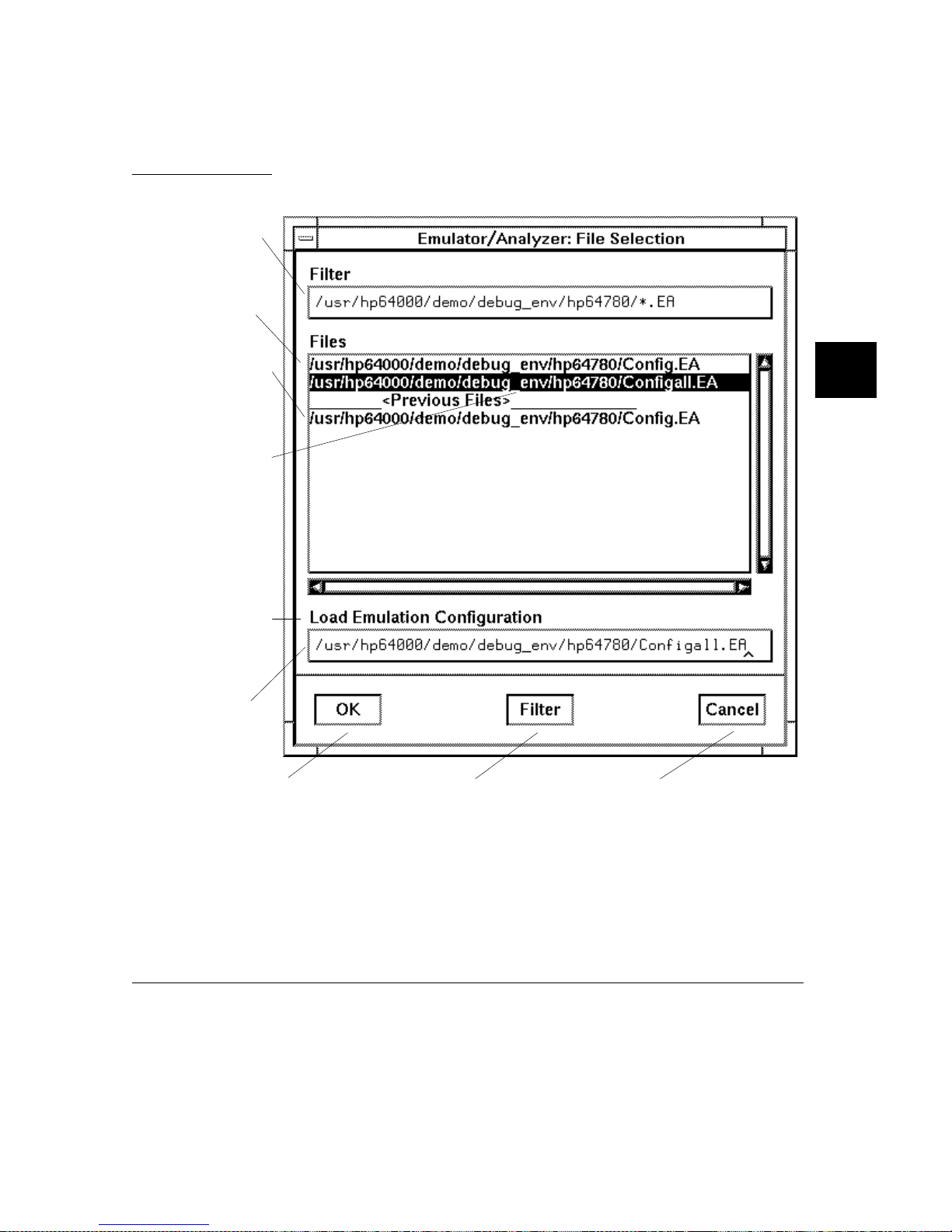
Using Menus, the Entry Buf fer, an d Action Keys
Examples To use the File Selectio n dialo g box:
The file filter selects
specific files.
A list of
filter -matchi ng fi le s
from th e cu r rent
directory.
A list of files
previously accessed
during the emulation
session.
A sin gl e click on a
file name from either
list highlights the file
name an d cop ie s it to
the text area. A
double click choose s
the file and closes the
dialog bo x.
Chapter 4: Entering Commands
Label informs you
what kind of file
selection you are
performing.
Text entry area.
Text is either
copied he re from
the recall list, or
entered dir ec tly.
Clicki ng th is button
chooses the file name
displayed in the text entry
area and closes the dial og
box.
Entering a new file filter
and clicki ng this butto n
causes a list of fil es
matching the new filter to
be read fro m the di re ct ory.
Clicki ng th is button
cancel s the file selection
operation and closes the
dialog bo x.
63
Page 84
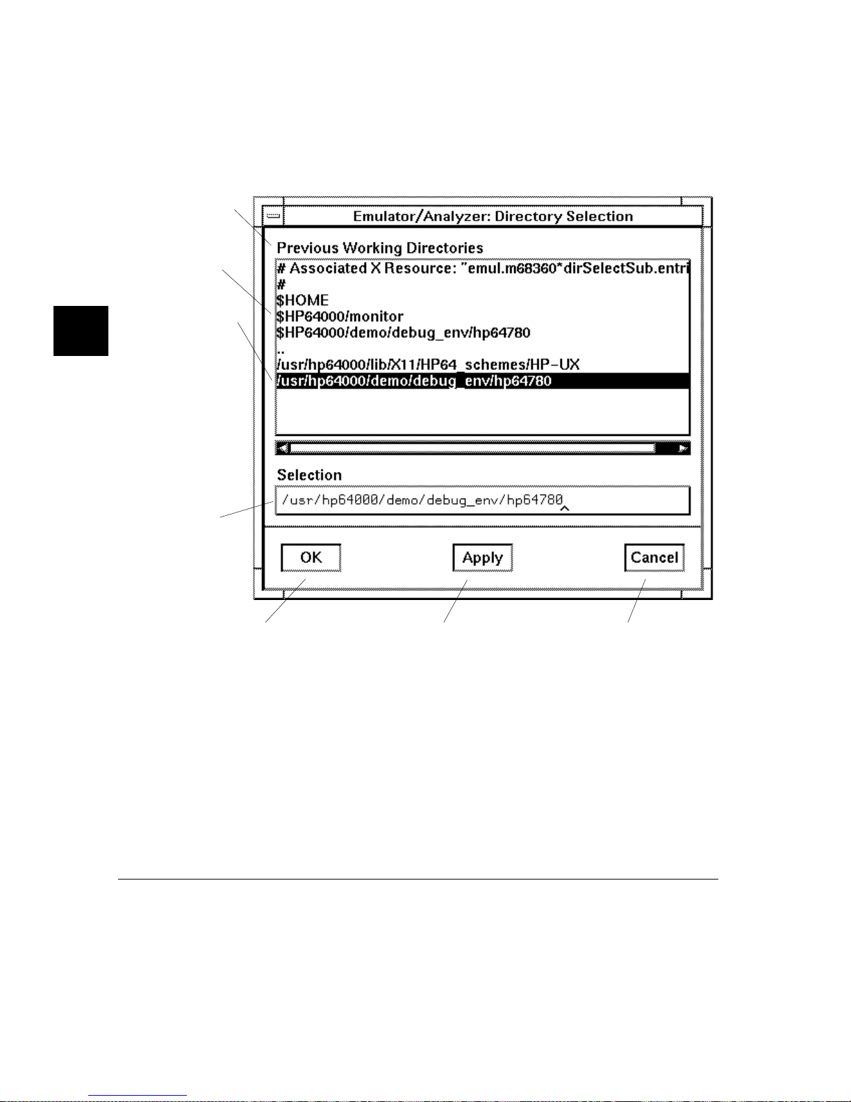
Chapter 4: Entering Commands
Using Menus, the Entry Buf fer, an d Action Keys
To use the Direc to ry Selection di al og bo x:
Label informs you
of the type of list
displayed.
A list of pred efi ne d
or previously
accessed dir ector ie s.
A sin gl e click on a
direct ory na m e fro m
the list high li ght s
the nam e an d cop ie s
it to the text area. A
dou ble cl ic k
chooses the
direct ory a nd closes
the dial og b o x.
Text entry area.
Direc tory name is
either copied here
from the recall list,
or ent ere d directl y.
64
Clicki ng th is button
chooses the dir ector y
displayed in the text entry
area and closes the dial og
box.
Clicki ng th is button
chooses the dir ector y
displayed in the text entry
area, but keeps the dialog
box on the screen instea d
of closing it.
Clicki ng th is button
cancel s the directory
selection operation and
closes the dia lo g box.
Page 85

Chapter 4: Entering Commands
Using Menus, the Entry Buf fer, an d Action Keys
To access help information
• Help av ai la ble in t he he lp inde x:
1 Display the Help Index by choosing Help→Gene ral Topic... or
Help→Command Line....
2 Choose a topic of interest from the Help Index.
The Help Index lists topics covering operation of the interface as well other
informa tion ab out the interface. When you choo se a topi c from t he Help In dex , the
interface displ ay s a window con ta ini ng the he lp inform at ion . You may leave the
window on the screen while you conti nue using the inter face.
• Help availa ble for use of th e Actio n Keys:
• General informa tion a bout usin g Act ion Keys in the 68360 emula to r is
availabl e by pressi ng th e "Help 360 " Acti on Ke y.
• Detailed inform a ti on for configu rin g a parti cula r SIM60 or CPM registe r can
be obtained by placing the nam e of the regi ste r in the entr y field and pressi ng
the "Help Reg ()" Acti on Key .
• Help for understanding ho w actio n key s work in the Graph ical User Int er face
is available in Cha pter 10, "Set ti ng X Resourc es. "
65
Page 86

Chapter 4: Entering Commands
Using the Command Lin e with the Mo use
Using the Command Line with the
Mouse
When using the Graphical User Interface, the command line portion of the inte rfa ce
gives you the opt ion of ent er ing command s in th e sam e manner as they are entered
in the Softkey Inte rfa ce . Additiona ll y, the gra phi cal in terfa ce makes t he softke y
labels pushbut ton s so comm and s ma y be entere d usin g the mouse.
If you are using the Soft key Interfa ce , using the comm and line with th e keyboa rd i s
the only way to enter comman ds.
This section desc rib es how t o:
• Turn the com ma nd l ine off/ on.
• Enter commands.
• Edit comman ds .
• Recall commands.
66
• Display the help window.
To tur n the command line on or off
• To turn the comm an d line on or off usi ng the pu lldown m en u, choose
Setting s→Com mand Li ne .
• To turn the comman d line on or off using t he status li ne pop-up menu: positio n the
mouse poi nte r within the status line are a, press and hold the select mouse button,
and choose Command Line Off from the menu.
• To turn the comman d line of f using the comman d line entr y are a pop-up menu:
position the mouse poi nter within th e en try area, press a nd ho ld the select mouse
button, and choo se Command Line Off from the me n u.
Page 87

Chapter 4: Entering Commands
Using the Command Line with the Mous e
Turns display of the comm and line area "on" or "off ." On means tha t the comma nd
line is displayed and you can use the sof tkey la bel push but ton s, the com ma nd
return and rec all push but ton s, and th e cursor pushbuttons for c om ma nd line editi ng.
Off means the comm and li ne is not displ ay ed and you use onl y th e pulld own
menus and t he act ion keys t o con tro l the in te rfa ce .
The command l ine area be gi ns just below th e sta tu s lin e and con ti nue s to th e
bottom of the emula to r/analyz er windo w. The s t at us li ne i s not part of the
comma nd li ne and cont inues to be displayed whet he r the com m an d li ne is o n or off .
Choosing certain pulldown menu items whi le the command line is off causes t he
command li ne to be turned on. That is be cause t he m en u item cho sen re qui res
some input at the command line that cannot be supplied another way.
To enter a command
1 Build a command using the softkey label pushbu tt ons by succe ssiv ely posi tioni ng
the mouse pointe r on a pushbutto n and clicking the pushbutt on selec t m ouse button
until a complete command is formed.
2 Execut e th e complete d com m an d by cl ic king the Ret urn pushbutton (found near
the bottom of the command line in the "Command" group).
Or:
Execute the comp lete d comm and usin g the Com m and Line entr y area pop-up
menu: Position the mouse po int er in the comm and li ne entry ar ea ; press and hold
the selec t mouse but ton until the Comm a nd Line pop-up m enu appear s; then,
choose the Execute Command menu ite m.
You may need to combin e pushbut ton and keybo ard entry to form a comple te
comma nd.
A complet e com ma nd i s a stri ng of softk ey l abe ls a nd te xt entere d wit h th e
keyboard. You know a command is comp le te when Return pushbut to n is not
halfbrig ht. The inte rfa ce does no t check or act on a comman d, howev er, unt il the
command is e xecut ed. (In cont rast , comm and s resul ti ng fr om pulldown menu
67
Page 88

Chapter 4: Entering Commands
Using the Command Lin e with the Mo use
choices and action keys are supplied with the needed carr iage return as part of the
comma nd.)
To edit the command line using the command
lin e pushbuttons
• To cl ea r the com m and line, click the Cle ar pushbutton.
• To clear the command line from the cursor posi tion to the end of the line, click the
Clear to e n d pushbutton.
• To move to the right one comm and word or token, click th e Forwa rd pushbutton.
• To move to the left one command word or tok en, click the Backup pushb utt on.
• To insert charac ters at the cursor posi ti on, pre ss the inse rt key to change to
insertion m ode , and th en type the cha racte rs to be insert ed .
68
• To delete charac ters to the left of the cursor po sition, press the <BACK SP ACE>
key.
When the cursor arrive s at the begi nni ng of a comm and word or token, the soft key
labels change to display the possib le choi ces at that level of the com mand.
When moving by words left or right, the Forward pushbutton becomes ha lfbright
and unresponsive when the cursor reaches th e end of the comma nd string .
Similarly , the Ba ckup push but ton becom es halfb rig ht and unr espo nsiv e when the
cursor reache s the beginni ng of the comm and .
See "To edit the command line using the mou se and the comm and line po p-up
menu" and "T o ed it the comm and line using th e keyboa rd" for inform ation about
additional editi ng op era tions yo u can per form .
Page 89

Chapter 4: Entering Commands
Using the Command Line with the Mous e
To edit the command line using the command
line pop-up menu
• To clear the comm an d line: posi tion th e mouse poin ter wit hin the Com mand L ine
entry area; press and hold the select mouse button until the Command Line pop-up
menu appears; c hoose Cle ar Entire Line fro m the menu.
• To clear the command line from the cursor posi tion to the end of the line: positio n
the mouse pointer at the place wher e you want the clear-to -en d to start; pr ess and
hold t he s elect mouse but to n unt il the Comma nd L in e pop -up men u app ea rs;
choose Clear to End of Line from the menu.
• To position th e cursor a nd in sert chara ct ers a t the cursor l oca tion: posi ti on th e
mouse pointe r in a non-text area of the comma nd line entry ar ea; pre ss and hold the
select mou se butto n to displ ay the Comma nd Line pop-up menu; choose Posi tio n
Cursor, Inser t M ode from the menu; type the characters to be inserted.
• To replace charac ters at the cur ren t cursor l ocati on: positi on the mouse pointer in a
non-text area of the com mand line entry area; press and hol d th e select mouse
button to displ ay the Com mand L in e pop -up men u; c hoose Positi on Curso r,
Replace Mode from the me nu; typ e th e character s to be inserted.
• To position th e cursor a nd re pla ce cha ract ers a t the cursor l oca tion: position th e
mouse pointe r in a non-text area of the comma nd line entry ar ea; pre ss and hold the
select mou se butto n to displ ay the Comma nd Line pop-up menu; choose Posi tio n
Cursor, Repl ace Mode from the menu; type the characters to be inserted.
When the cursor arrive s at the begi nni ng of a comm and word or token, the soft key
labels change to display the possib le choi ces at that level of the com mand.
See "To edit the comma nd line using the mouse an d the comm and line
pushbutton s" and "T o ed it the com mand line using the keyboa rd" fo r inf orm at io n
about addi tional editin g ope rat ions you can perfo rm.
69
Page 90

Chapter 4: Entering Commands
Using the Command Lin e with the Mo use
To recall commands
1 Click the pushbutton labeled Rec all in the Command Line to display the dialog box.
2 Choose a command from the buffer list. (You can also enter a command directly
into the t ext ent ry a rea of the dial og b ox .)
Because all comm and entry m ethods i n the inter fac e — pulldown menus, acti on
keys, and command l ine ent ri es — a re e choed to the command line e ntry area, th e
contents of the Command Recall dialog box is not restricted to just commands
entered directly int o the com m an d li ne e ntry area.
The Command Recall dialog box contains a list of interface commands executed
during the sessio n as wel l as any prede fi ned comm and s present at interface sta rtu p.
If you exit the emula tion/analysis sessi on wi th the i nterface "locked", commands in
the recall buffe r are saved a nd wil l be pre sent when you resta rt the i nterface.
You can predefine e ntr ies for th e Com m an d Recal l dialog bo x and defi ne the
maximum num ber of entri es by sett ing X resource s (refer to Cha pte r 10, "Set ting X
Resources").
70
See "To use dial og box es" for info rm ation about using dial og box es.
To get help about the c ommand line
• To display the help topic expla ining t he opera tion of the comm and line, pre ss the
Help pushbutton located near the bottom-ri ght corn er of the Comma nd Lin e area.
Page 91

Chapter 4: Entering Commands
Using the Command Lin e with the Keybo ard
Using the Command Line with the
Keyboard
When using the comm and line wit h the keyboa rd, you enter com mands by pressing
softkeys whose label s appear at the bottom of the screen . Softkeys prov ide for
quick command entry, and minimize the possibility of errors.
The command line also prov ides com m and compl et ion. You can type the first few
character s of a comma nd (enough to uniquely ide nt ify the comm and ) and then
press <Tab>. The inter face com ple tes the comm an d word for you.
Entering co mm ands with the keyboard i s easy . However , the inte rfa ce prov ide s
other featur es th at make ente ri ng co mm a nds ev en easi er. For exam pl e, you c an:
• Enter multiple commands on one line.
• Recall commands.
• Edit comman d s.
• Access on-li ne help inf orm at io n.
To enter multiple comman d s on one comman d
line
• Separate the comm an ds wit h semic ol ons (; ).
More than one comman d may be entered in a single comm and line if the
commands are sep arate d by semi co lon s (;).
Examples To reset the emula tor and br eak int o th e monitor:
reset
;
break
<RETURN>
71
Page 92

Chapter 4: Entering Commands
Using the Command Lin e with the Keybo ard
To recall commands
• Press <CTRL>r or <CTRL>b.
The most recent 20 comm a nds you enter are store d in a buffe r and may be recalle d
by pressing <C TR L>r. Pressing < CT RL >b cycles for ward thro ugh the re call
buffer.
Examples For example, to recall an d execu te the comm and prio r to the last comm and :
<CTRL>r <CTRL>r <RETURN>
To edit commands
• Use the <Le ft arrow>, <Right arrow>, <Tab>, <Shift><Tab> , <Insert char>,
<Back sp a ce >, <De le te cha r>, <C le ar l ine>, and <CTRL> u key s.
72
The <Left arrow> an d <Ri ght arr ow> ke ys move the cursor single spac es to the left
or right.
The <Tab> and <Shift><T ab > keys move the cursor to the next or previous word
on the com ma nd l ine .
The <Insert char> key enter s the insert edit in g mode and allows cha rac ters or
command opt io ns to be inse rt ed at the cursor l oca ti on.
The <Back space > key delet es the c har acte r to the left of the cursor.
The <Delet e char> key del et es th e chara cter to the ri ght of the cur sor.
The <Clear line> key delete s the chara ct ers fr om the cursor to the end of t he line .
The <CTRL>u key erases the command line.
Page 93

Using the Command Lin e with the Keybo ard
To access on-line help information
• Use the help or ? c ommands.
To access the comm and line’s on-li ne help inform at io n, type eithe r help or ? on the
command line . You will notice a new set of softk eys. By pressin g one of these
softkeys and <RET URN>, you can displ ay inform at ion on that topi c.
Examples To display informatio n on the system comm an ds:
help
system_commands
Or:
?
system_commands
The help information is scro lled on to the screen. If there is more than a screen full
of information, you will have to press t he space bar to see the nex t scree n full, or
the <RETURN> key to see the next line , just as you do with the UNIX m ore
comma nd. Afte r all th e information on t he pa rticular to pic has been displayed (or
after you press "q" to quit scroll ing through i nfor ma tion) , you are prom pt ed to
press <RETURN> to return to the command line.
<RETURN>
<RETURN>
Chapter 4: Entering Commands
73
Page 94

Chapter 4: Entering Commands
Using Command Files
Using Command Files
You can execute a series of co mm a nds th at have been sto red in a command fi le .
You can create comm an d files by logg ing comm and s whil e using th e inte rfa ce or
by using an editor on your host comput er .
Once you cre at e a com ma nd fi le , you can execute the fil e in the em ul at ion
environment by typing the name of the file on the command line and pressing
<RETURN>.
Command fil es e xecut e unt il an end-o f-fi le is fou nd or un til a synta x error oc cur s.
You can stop a command file by pressin g <CTRL > c or the <Break> key .
This section shows you how to:
• Start logging commands to a command file.
• Stop logging com m an ds to a comm and fil e.
• Playback (execute) a command file.
Nesting Command Files
74
You can nest a maxim um of e igh t leve ls of c om ma nd fi le s. Nesti ng co mma nd fi le s
means one com mand file calls ano the r.
Comments in Command Files
Text that follows a pou nd sig n (#), up to the end of the line, is inte rpr eted a s a
comm e nt.
Using the wait Co mmand
When editi ng command fi le s, you can insert wa it commands t o pau se ex ecuti on of
the comm a nd fi le at cert ai n poi nts.
If you press <CT RL>c to stop ex ec ution of a command file while the "wai t"
comma nd is be ing execu te d from th e comm a nd file, the <CTRL>c will term inate
the "wait" com mand, but wil l not te rm inate com man d fil e exec ut ion . To do this,
press <CT RL>c agai n.
Page 95

Chapter 4: Entering Commands
Using Command Files
Use the wait measurem ent_ com ple te com m and aft er chan ging the trace dep th.
By doing this, when you copy or displa y the trace after cha ngi ng the trac e depth ,
the new trace states will be available . Othe rwise the new stat es won’ t be avail abl e.
Passing Parameters
Command fil es pr ovi de a conv enien t met hod fo r passi ng pa ra mete rs by usi ng a
parame te r dec la ration line preced ing the com m and s in th e co mm a nd fi le . When
the command file is called, the system will promp t you for current valu es of the
for ma l p aramete rs liste d.
Parameters are defined as:
Passed Parame te rs - These are ASCII strings passed to a command fil e. Any
continuous set of ASCII char acters ca n be passed. Spaces sepa rat e the
parameters.
Formal Parameters - These are sym bol s pre ce ded by an amp ersa nd ( & ),
which are the variables of the command file.
The ASCII string passed (passe d parame ter) will be subst ituted for the formal
parameter when the comm and file is execut ed.
The only w a y to pa s s a pa rameter con taining a spac e is t o enc lo se the param e te r in
double quotes (") or single quotes (’). Thus, to pass the paramet er HP 9000 to a
command fi le, yo u can use eit her "HP 9000" or ’HP 90 00’.
The s pecial pa rameter &ArG_l EfT gets set to all the remaining parameters
specifie d when the com m an d fil e was invoked. This let s you use var ia ble siz e
paramete r lists. If no parame te rs are left, &ArG_lEfT gets set to NULL .
Consider the command fi le example (named CMDFIL E) shown be low:
PARMS &ADDR &VALUE1
#
# modify a location or list of locations in memory
# and display the result
#
modify memory &ADDR words to &VALUE1 &ArG_lEfT
display memory &ADDR blocked words
75
Page 96

Chapter 4: Entering Commands
Using Command Files
When you execute CMDFILE, you will be prompt ed with:
Define command file parameter [&ADDR]
To pass the parame ter, enter the addr ess of t he first memo ry lo ca tion to be
modifie d. You wil l then be prom pt ed for &VALUE1 . If you ente r, for e xam pl e,
"0,-1,20, 0ffffh , 4+5*4 ", the first param eter "0, -1 ,20, " is passed to & VALUE1 and
the remaining param eters "0f fffh ," and "4+5*4" are passed to &Ar G _lE fT.
You can also pass the param eter s when yo u invoke the command file (for example,
CMDFILE 1000h 0,-1,20, 0ffffh, 4+5*4) .
Other Things to Know About Command Files
You should know the follo wing about usi ng comma nd file s:
1 Command fil es m ay contain sh e ll vari ables. Onl y tho se sh e ll vari ables
beginnin g wit h "$" fol lowe d by an ide nt ifi er will be sup ported. An identif ier
is a sequenc e of lette rs, digi ts or unde rsco res be gi nni ng with a letter or
underscore . The identifi er may be encl osed by brace s "{ }" or entere d dir ec tly
following the "$" symbol. Braces are required when the identifier is followed
by a letter, a digit or an undersco re that is not inter pre ted as part of its name.
For example, assume a directory name d /users/ soft ke ys and the shel l variabl e
"S". The value of "S" is "soft". By specifying the directo ry as /user s/${S}keys
the correct resul t is obta in ed. However, if you atte mpt t o specif y the direc tor y
as /users/$Sk eys, the Softke y Int erf ace lo oks for the value of the vari able
"Skeys". This is not the oper ators in te nde d resu lt. You may not get the
intended resu lt unless Skeys is already defi ned to be "softk eys".
76
You can examine the curre nt val ues of all shell va ri ables de fi ned in your
environm ent with the comm a nd "en v".
2 Positional shell variables, suc h as $1, $2, and so on, are not supported. Neither
are special shell variabl es, such as $@, $*, and so on, support ed.
3 You can continue comm a nd fi le lines. This is don e by a voi din g the li ne feed
with a back sla sh (\) . A line terminat ed by "\" is concatenate d wit h an y
following lines unt il a line that doe s not contai n a backslash is found. A line
constructed in this m ann er is rec ogni ze d and exe cu ted as one sing le comm and
line. If the last lin e in a comm an d fil e is terminate d by "\", it app ears on the
command line but is not execut ed. Normal ly , the line feed is reco gni ze d as the
command term inator. The UNIX env ironment recogn iz es th ree quoting
Page 97

Chapter 4: Entering Commands
Using Command Files
character s for she ll com m and s which are double quot es ("), sin gle quot es (’ ),
and the backslash symbo l (\).
For example, th e follo wing thre e line s are treat ed as a single shel l com ma nd.
The two hidden line feeds are ignored because they are insi de the two single
quotes (’):
!awk ’/$/ { blanks++ }
END { print blanks }
’ an_unix_fil e
To start logging commands to a command file
• Choose File→Log→Record and use the dialog box to select a command file name.
• Using the command line, enter the log_comm ands to <file> command.
To stop logging commands to a command file
• Choose File→Log→Stop.
• Using the command line, enter the log_commands off command.
77
Page 98

Chapter 4: Entering Commands
Using Command Files
To playback (execute) a command file
• Choose File→Log→Playback and use the dia lo g box t o sel ec t the na me of th e
command file you wish to exec ute.
• Using the command line, enter the name of the command file and press
<RETURN>.
If you enter the name of the command file in the command line and the interface
cannot find the comma nd fi le in the cu rre nt di rectory, it sea rch es th e di rec tories
specified in the HP64KPATH environment variable.
To interrupt playback of a comma nd fi le, pr ess th e <CTR L> c key co mb ina ti on.
(The mouse poi nt er must be withi n the inter face window.)
If you press <CT RL>c to stop ex ec ution of a command file while the "wai t"
comma nd is be ing execu te d from th e comm a nd file, the <CTRL>c will term inate
the "wait" com mand, but wil l not te rm inate com man d fil e exec ut ion . To do this,
press <CT RL>c agai n.
78
Page 99

Chapter 4: Entering Commands
Using Pod Commands
Using Pod Commands
Pod commands a re Ter mina l Int er face com ma nds. The Term inal Int erf ac e is the
low-leve l in te rfa ce that re side s in the fi rm ware of the emula tor .
A pod command use d in the Graph ic al User Int er fac e bypasse s the inter fac e and
goes directl y to the emu lator. Because some pod co mm ands ca n cause the
interface to become out- of-sy nc wi th the emu lator, or even cause the inte rfa ce to
termin at e abnorm a ll y, the y mu st be used wi th care .
For example, if you ch ang e co nfi gura ti on i tems, th e actu al state of the emula to r
will no longer mat ch the int ern al rec ord t he inte rfa ce kee ps ab out the state of the
emulator .
Issuing certain comm un ic ation s-re la ted com man ds ca n preven t th e interfa ce from
commun ic at ing with the emulator and cause abnorma l term in at ion of the inter fac e.
However, it is some time s necessa ry t o use po d comm ands. For example, you must
use a pod command t o exe cute the emula to r’s pe rformance verification (pv)
routine. Perform an ce verifi ca tion is an int er nal sel f-t est proc edu re fo r the emul at or.
Remember that pod comm and s can cau se tr oubl e fo r the hig h-l eve l interface if they
are used indiscriminately.
This section shows you how to:
• Display the pod comma nds sc reen.
• Use pod comman ds.
79
Page 100

Chapter 4: Entering Commands
Using Pod Commands
To display the po d comma n ds scree n
• Choose Display→Pod Commands.
The pod comman ds scre en displ ay s the resul ts of pod (Ter mi na l Inter fac e)
commands. To set the inte rfa ce to use pod co mm ands, cho ose Setti ngs →Pod
Command Keyboar d .
To use pod commands
• To begin using pod comm ands, choose Setting s→ Pod Command Keyboard.
• To end using pod comma nds, click the suspend pushbutton softkey.
The Se ttings→P od Comm and Keybo ard com ma nd di splays the pod com man d s
screen and act iv ates the keyboard for entering pod comma nd on t he com ma nd l ine .
Examples To see a list of pod comm an d cate gories availa bl e, cho ose Se tti ng s→Pod
Command Keyboar d , and on t he c ommand line, type: he lp.
To see a list of pod com m an ds that control the em ula to r, type : he lp emul .
To see details of t he emu la tor "r" (run user code) com m and , type : help r.
80
 Loading...