

HP Disk Carrier Blade for bh3710, Management LAN Blade for bh7800, bh3710 Installation Manual
Page 1

hp Carrier Grade Blade Server
bh3710
Installation Guide
Manufacturing Part Number:
USA
© Copyright 2002
Second Edition
September 2002
Page 2

ii
Legal Notices
The information in this document is subject to change without notice.
Hewlett-Packard makes no warranty of any kind with regard to this manual, including, but not limited to, the
implied warranties of merchantability and fitness for a particular purpose. Hewlett-Packard shall not be held
liable for errors contained herein or direct, indirect, special, incidental or consequential damages in
connection with the furnishing, performance, or use of this material.
Restricted Rights Legend. Use, duplication or disclosure by the U.S. Government is subject to restrictions
as set forth in subparagraph (c) (1) (ii) of the Rights in Technical Data and Computer Software clause at
DFARS 252.227-7013 for DOD agencies, and subparagraphs (c) (1) and (c) (2) of the Commercial Computer
Software Restricted Rights clause at FAR 52.227-19 for other agencies.
HEWLETT-PACKARD COMPANY 3000 Hanover Street Palo Alto, California 94304 U.S.A.
Copyright Notices. ©copyright 1983-2002 Hewlett-Packard Company, all rights reserved.
Reproduction, adaptation, or translation of this document without prior written permission is prohibited,
except as allowed under the copyright laws.
Page 3

Contents
iii
1. hp Carrier Grade Server bh3710 Overview
Introduction . . . . . . . . . . . . . . . . . . . . . . . . . . . . . . . . . . . . . . . . . . . . . . . . . . . . . . . . . . . . . . . . . . . . . . . . . 1
Network Equipment-Building Systems (NEBS) Compliance. . . . . . . . . . . . . . . . . . . . . . . . . . . . . . . . . 1
Installation Guide Contents . . . . . . . . . . . . . . . . . . . . . . . . . . . . . . . . . . . . . . . . . . . . . . . . . . . . . . . . . . . 1
Audience Assumptions . . . . . . . . . . . . . . . . . . . . . . . . . . . . . . . . . . . . . . . . . . . . . . . . . . . . . . . . . . . . . . . 1
2. Unpacking and Installing the hp Carrier Grade Blade Server bh3710
Introduction . . . . . . . . . . . . . . . . . . . . . . . . . . . . . . . . . . . . . . . . . . . . . . . . . . . . . . . . . . . . . . . . . . . . . . . . . 1
Site Preparation . . . . . . . . . . . . . . . . . . . . . . . . . . . . . . . . . . . . . . . . . . . . . . . . . . . . . . . . . . . . . . . . . . . . 1
Unpacking the Blade Server . . . . . . . . . . . . . . . . . . . . . . . . . . . . . . . . . . . . . . . . . . . . . . . . . . . . . . . . . . 1
Installing the bh3710 Blade Server in a Rack . . . . . . . . . . . . . . . . . . . . . . . . . . . . . . . . . . . . . . . . . . . . . . 2
3. hp Carrier Grade Server bh3710 Power and Cooling Component Overview
Introduction . . . . . . . . . . . . . . . . . . . . . . . . . . . . . . . . . . . . . . . . . . . . . . . . . . . . . . . . . . . . . . . . . . . . . . . . . 1
DC Power Supplies. . . . . . . . . . . . . . . . . . . . . . . . . . . . . . . . . . . . . . . . . . . . . . . . . . . . . . . . . . . . . . . . . . . . 2
Grounding . . . . . . . . . . . . . . . . . . . . . . . . . . . . . . . . . . . . . . . . . . . . . . . . . . . . . . . . . . . . . . . . . . . . . . . . . 3
Blade Server Power Supply Connector . . . . . . . . . . . . . . . . . . . . . . . . . . . . . . . . . . . . . . . . . . . . . . . . . . 4
DC Power Input Module and Cable Connector Pinout Information. . . . . . . . . . . . . . . . . . . . . . . . . . 4
Blade Server Cooling System . . . . . . . . . . . . . . . . . . . . . . . . . . . . . . . . . . . . . . . . . . . . . . . . . . . . . . . . . . . 6
4. Applying Power to the hp Blade Server bh3710
Introduction . . . . . . . . . . . . . . . . . . . . . . . . . . . . . . . . . . . . . . . . . . . . . . . . . . . . . . . . . . . . . . . . . . . . . . . . . 1
hp Blade Server Initial Power-Up . . . . . . . . . . . . . . . . . . . . . . . . . . . . . . . . . . . . . . . . . . . . . . . . . . . . . . . . 1
Chassis and Management Blade Power-Up . . . . . . . . . . . . . . . . . . . . . . . . . . . . . . . . . . . . . . . . . . . . . . 1
bp2200 Server Blade Power-Up . . . . . . . . . . . . . . . . . . . . . . . . . . . . . . . . . . . . . . . . . . . . . . . . . . . . . . . . 1
Blade Server Power-Down . . . . . . . . . . . . . . . . . . . . . . . . . . . . . . . . . . . . . . . . . . . . . . . . . . . . . . . . . . . . . . 2
Power-Down the bp2200 and Management Blades. . . . . . . . . . . . . . . . . . . . . . . . . . . . . . . . . . . . . . . . . 2
Chassis Power-Down. . . . . . . . . . . . . . . . . . . . . . . . . . . . . . . . . . . . . . . . . . . . . . . . . . . . . . . . . . . . . . . . . 2
5. hp Carrier Grade Server bh3710 Server Blade Installation Information
Introduction . . . . . . . . . . . . . . . . . . . . . . . . . . . . . . . . . . . . . . . . . . . . . . . . . . . . . . . . . . . . . . . . . . . . . . . . . 1
Server Blades . . . . . . . . . . . . . . . . . . . . . . . . . . . . . . . . . . . . . . . . . . . . . . . . . . . . . . . . . . . . . . . . . . . . . . . . 2
Display Panel Blade Status Indicators . . . . . . . . . . . . . . . . . . . . . . . . . . . . . . . . . . . . . . . . . . . . . . . . . . 4
Management Blade . . . . . . . . . . . . . . . . . . . . . . . . . . . . . . . . . . . . . . . . . . . . . . . . . . . . . . . . . . . . . . . . . . . 5
Management Blade LED Definitions. . . . . . . . . . . . . . . . . . . . . . . . . . . . . . . . . . . . . . . . . . . . . . . . . . . . 5
Management Blade Configuration. . . . . . . . . . . . . . . . . . . . . . . . . . . . . . . . . . . . . . . . . . . . . . . . . . . . . . 6
Configuring the Management Blade . . . . . . . . . . . . . . . . . . . . . . . . . . . . . . . . . . . . . . . . . . . . . . . . . . 6
Pre-Configuration Assumptions. . . . . . . . . . . . . . . . . . . . . . . . . . . . . . . . . . . . . . . . . . . . . . . . . . . . . . 6
LAN Cabling Requirements. . . . . . . . . . . . . . . . . . . . . . . . . . . . . . . . . . . . . . . . . . . . . . . . . . . . . . . . . 6
Configuration Procedures. . . . . . . . . . . . . . . . . . . . . . . . . . . . . . . . . . . . . . . . . . . . . . . . . . . . . . . . . . . 7
Management Blade Configuration. . . . . . . . . . . . . . . . . . . . . . . . . . . . . . . . . . . . . . . . . . . . . . . . . . 7
bp2200 Server Blade . . . . . . . . . . . . . . . . . . . . . . . . . . . . . . . . . . . . . . . . . . . . . . . . . . . . . . . . . . . . . . . . . . 8
GSP Reset and Transfer of Control (TOC) Buttons . . . . . . . . . . . . . . . . . . . . . . . . . . . . . . . . . . . . . . . . 9
bp2200 Server Blade LED Definitions . . . . . . . . . . . . . . . . . . . . . . . . . . . . . . . . . . . . . . . . . . . . . . . . . . 9
bp2200 Management Processor (MP) Configuration . . . . . . . . . . . . . . . . . . . . . . . . . . . . . . . . . . . . . . 10
Configuring the MP. . . . . . . . . . . . . . . . . . . . . . . . . . . . . . . . . . . . . . . . . . . . . . . . . . . . . . . . . . . . . . . 10
Page 4

Contents
iv
Pre-Configuration Assumptions. . . . . . . . . . . . . . . . . . . . . . . . . . . . . . . . . . . . . . . . . . . . . . . . . . . . . 10
LAN Cabling Requirements. . . . . . . . . . . . . . . . . . . . . . . . . . . . . . . . . . . . . . . . . . . . . . . . . . . . . . . . 10
Configuration Procedures. . . . . . . . . . . . . . . . . . . . . . . . . . . . . . . . . . . . . . . . . . . . . . . . . . . . . . . . . . 10
Management Blade Configuration. . . . . . . . . . . . . . . . . . . . . . . . . . . . . . . . . . . . . . . . . . . . . . . . . 11
Management Processor Network Parameters Configuration. . . . . . . . . . . . . . . . . . . . . . . . . . . . 11
Access the MP Console.. . . . . . . . . . . . . . . . . . . . . . . . . . . . . . . . . . . . . . . . . . . . . . . . . . . . . . . . . . . . 11
Boot Procedures . . . . . . . . . . . . . . . . . . . . . . . . . . . . . . . . . . . . . . . . . . . . . . . . . . . . . . . . . . . . . . . . . . . 12
Boot Console Handler (BCH) Boot Procedures . . . . . . . . . . . . . . . . . . . . . . . . . . . . . . . . . . . . . . . . . 12
Boot to the HP-UX Prompt . . . . . . . . . . . . . . . . . . . . . . . . . . . . . . . . . . . . . . . . . . . . . . . . . . . . . . . . . 12
Rebooting to the HP-UX Prompt . . . . . . . . . . . . . . . . . . . . . . . . . . . . . . . . . . . . . . . . . . . . . . . . . . . . 13
Fibrechannel (FC) and LAN Rear Transition Module (RTM) Blade. . . . . . . . . . . . . . . . . . . . . . . . . . . . 14
FC and LAN RTM LED Definitions. . . . . . . . . . . . . . . . . . . . . . . . . . . . . . . . . . . . . . . . . . . . . . . . . . . . 15
FC and LAN RTM Ports . . . . . . . . . . . . . . . . . . . . . . . . . . . . . . . . . . . . . . . . . . . . . . . . . . . . . . . . . . . . . 15
LAN Connectivity to the FC and LAN RTM Ports . . . . . . . . . . . . . . . . . . . . . . . . . . . . . . . . . . . . . . . . 15
LAN Connectivity Pre-installation Preparation . . . . . . . . . . . . . . . . . . . . . . . . . . . . . . . . . . . . . . . . 15
Fibre Channel (FC) Disk Carrier . . . . . . . . . . . . . . . . . . . . . . . . . . . . . . . . . . . . . . . . . . . . . . . . . . . . . . . 18
FC Disk Drive LED Definitions . . . . . . . . . . . . . . . . . . . . . . . . . . . . . . . . . . . . . . . . . . . . . . . . . . . . . . . 19
Installing and Removing Blades . . . . . . . . . . . . . . . . . . . . . . . . . . . . . . . . . . . . . . . . . . . . . . . . . . . . . . . . 20
Removing and Installing Slot Blockers . . . . . . . . . . . . . . . . . . . . . . . . . . . . . . . . . . . . . . . . . . . . . . . . . 21
Remove the Slot Blocker . . . . . . . . . . . . . . . . . . . . . . . . . . . . . . . . . . . . . . . . . . . . . . . . . . . . . . . . . . . 21
Install the Slot Blocker . . . . . . . . . . . . . . . . . . . . . . . . . . . . . . . . . . . . . . . . . . . . . . . . . . . . . . . . . . . . 21
Installing and Removing Blades With Locking Levers . . . . . . . . . . . . . . . . . . . . . . . . . . . . . . . . . . . . 22
Installing Blades With Locking Levers . . . . . . . . . . . . . . . . . . . . . . . . . . . . . . . . . . . . . . . . . . . . . . . 22
Removing Blades With Locking Levers . . . . . . . . . . . . . . . . . . . . . . . . . . . . . . . . . . . . . . . . . . . . . . . 24
Installing and Removing Carrier Blades. . . . . . . . . . . . . . . . . . . . . . . . . . . . . . . . . . . . . . . . . . . . . . . . 27
Installing the Carrier Blade . . . . . . . . . . . . . . . . . . . . . . . . . . . . . . . . . . . . . . . . . . . . . . . . . . . . . . . . 27
Removing the Carrier Blade . . . . . . . . . . . . . . . . . . . . . . . . . . . . . . . . . . . . . . . . . . . . . . . . . . . . . . . . 28
6. Communication with the hp Carrier Grade Blade Server bh3710
Introduction . . . . . . . . . . . . . . . . . . . . . . . . . . . . . . . . . . . . . . . . . . . . . . . . . . . . . . . . . . . . . . . . . . . . . . . . . 1
Remote Installation of Operating Systems. . . . . . . . . . . . . . . . . . . . . . . . . . . . . . . . . . . . . . . . . . . . . . . . . 1
The Support Tool Manager. . . . . . . . . . . . . . . . . . . . . . . . . . . . . . . . . . . . . . . . . . . . . . . . . . . . . . . . . . . . 1
7. Specifications for the hp Carrier Grade Server bh3710
Introduction . . . . . . . . . . . . . . . . . . . . . . . . . . . . . . . . . . . . . . . . . . . . . . . . . . . . . . . . . . . . . . . . . . . . . . . . . 1
A. LVM Boot Device Hardware PathChange for the hp Carrier Grade Server bh3710
Page 5

Figures
v
Figure 0-1. Power Supply Locations . . . . . . . . . . . . . . . . . . . . . . . . . . . . . . . . . . . . . . . . . . . . . . . . . . . 2
Figure 0-2. hp Blade Server DC Power Supply Input Module (Server Rear View) . . . . . . . . . . . . . . 3
Figure 0-3. hp Blade Server DC Power Supply Output Module (Server Front View) . . . . . . . . . . . . 3
Figure 0-4. DC Power Cable . . . . . . . . . . . . . . . . . . . . . . . . . . . . . . . . . . . . . . . . . . . . . . . . . . . . . . . . . 4
Figure 0-5. DC Power Connector Pin location . . . . . . . . . . . . . . . . . . . . . . . . . . . . . . . . . . . . . . . . . . . 5
Figure 3-6. Cooling Airflow into the Blade Server . . . . . . . . . . . . . . . . . . . . . . . . . . . . . . . . . . . . . . . . 6
Figure 5-1. Rear View of Chassis With Blades Installed . . . . . . . . . . . . . . . . . . . . . . . . . . . . . . . . . . . 3
Figure 5-2. Front View of Chassis With Blades Installed . . . . . . . . . . . . . . . . . . . . . . . . . . . . . . . . . . 4
Figure 5-3. Management Blade . . . . . . . . . . . . . . . . . . . . . . . . . . . . . . . . . . . . . . . . . . . . . . . . . . . . . . . 5
Figure 5-4. Management Blade Bulkhead Label . . . . . . . . . . . . . . . . . . . . . . . . . . . . . . . . . . . . . . . . . 5
Figure 5-5. Identification Legend Marking. . . . . . . . . . . . . . . . . . . . . . . . . . . . . . . . . . . . . . . . . . . . . . 6
Figure 5-6. bp2200 Server Blade. . . . . . . . . . . . . . . . . . . . . . . . . . . . . . . . . . . . . . . . . . . . . . . . . . . . . . 8
Figure 5-7. bp2200 Blade Bulkhead Label . . . . . . . . . . . . . . . . . . . . . . . . . . . . . . . . . . . . . . . . . . . . . . 8
Figure 5-8. bp2200 Identification Legend Marking . . . . . . . . . . . . . . . . . . . . . . . . . . . . . . . . . . . . . . . 8
Figure 5-9. FC and LAN RTM Blade . . . . . . . . . . . . . . . . . . . . . . . . . . . . . . . . . . . . . . . . . . . . . . . . . 14
Figure 5-10. FC and LAN RTM Blade Bulkhead Label . . . . . . . . . . . . . . . . . . . . . . . . . . . . . . . . . . . 14
Figure 5-11. Fibrechannel and LAN RTM Identification Legend Marking . . . . . . . . . . . . . . . . . . . 14
Figure 5-12. bh3710 Chassis (Rear View) . . . . . . . . . . . . . . . . . . . . . . . . . . . . . . . . . . . . . . . . . . . . . 16
Figure 5-13. FC Disk Carrier. . . . . . . . . . . . . . . . . . . . . . . . . . . . . . . . . . . . . . . . . . . . . . . . . . . . . . . . 18
Figure 5-14. FC Disk Carrier Legend Marking . . . . . . . . . . . . . . . . . . . . . . . . . . . . . . . . . . . . . . . . . 18
Figure 5-15. FC Disk Drive Bulkhead Label . . . . . . . . . . . . . . . . . . . . . . . . . . . . . . . . . . . . . . . . . . . 18
Figure 5-16. Slot Blocker . . . . . . . . . . . . . . . . . . . . . . . . . . . . . . . . . . . . . . . . . . . . . . . . . . . . . . . . . . . 21
Figure 5-17. Align Blades With Card Guides and Push Into Chassis . . . . . . . . . . . . . . . . . . . . . . . 22
Figure 5-18. Insert the Blade . . . . . . . . . . . . . . . . . . . . . . . . . . . . . . . . . . . . . . . . . . . . . . . . . . . . . . . 23
Figure 5-19. Tighten the Locking Screws . . . . . . . . . . . . . . . . . . . . . . . . . . . . . . . . . . . . . . . . . . . . . 23
Figure 5-20. Releasing Locking Levers . . . . . . . . . . . . . . . . . . . . . . . . . . . . . . . . . . . . . . . . . . . . . . . . 24
Figure 5-21. Loosen Locking Screws . . . . . . . . . . . . . . . . . . . . . . . . . . . . . . . . . . . . . . . . . . . . . . . . . . 25
Figure 5-22. Releasing Locking Levers . . . . . . . . . . . . . . . . . . . . . . . . . . . . . . . . . . . . . . . . . . . . . . . . 25
Figure 5-23. Pull Blade From Chassis . . . . . . . . . . . . . . . . . . . . . . . . . . . . . . . . . . . . . . . . . . . . . . . . 26
Figure 5-24. Two-Handled Blade. . . . . . . . . . . . . . . . . . . . . . . . . . . . . . . . . . . . . . . . . . . . . . . . . . . . . 27
Figure 5-25. FC Disk Carrier Blade . . . . . . . . . . . . . . . . . . . . . . . . . . . . . . . . . . . . . . . . . . . . . . . . . . 28
Page 6

Figures
vi
Page 7

vii
Preface
Printing History
The Printing History below identifies the edition dates of this manual. Updates are made to this publication
on an unscheduled, as needed, basis. The updates will consist of a complete replacement manual and
pertinent on-line or CD-ROM documentation.
First Edition April 2002
Second Edition September 2002
What’s New?
Customer documentation is reviewed, updated, and republished to ensure that information that was either
unknown or omitted from the previous edition, is included. Changes/additions in this edition are described as
follows:
• All chapters/appendices were reviewed and changes were made to correct format, grammar, and spelling.
• Chapters 3, 4, and 5 have been revised and realigned as follows:
— Chapter 3 now includes power and cooling system information, only.
— Chapter 4 is now the power application chapter. It was Chapter 5, initially.
— Chapter 5 is now Blade installation information and has been expanded to include more graphics,
new procedures, and configuration information. Server blade installation/removal instructions are
also included in this chapter.
• An index is included.
Page 8

viii
Page 9

Chapter 1
hp Carrier Grade Server bh3710 Overview
Introduction
1-1
1 hp Carrier Grade Server bh3710 Overview
Introduction
The hp Carrier Grade Blade Server bh3710 (called “blade server” in this manual) provides customers with a
single chassis that houses one server blade and up to four Fibre Channel disks in two dual Fibre Channel disk
carrier blades, controlled by one Management Blade. The form factor for all the blades uses the Compact PCI
standard. The chassis mounts in a standard 19 and/or 23-inch EIA two column rack. The chassis will
accommodate 10 full size Compact PCI cards (6U x 160mm) in the front slots and 10 half size Compact PCI
cards (6U x 80mm), called Rear Transition Modules (RTM), in the rear slots.
Network Equipment-Building Systems (NEBS) Compliance
This system is compliant with NEBS Level 3 requirements as defined in GR63 and GR1089 standards.
Installation Guide Contents
Before installing your blade server, familiarize yourself with the components that comprise the bh3710. Use
the following reference to determine where you would like to start.
• Chapter 1 - Introduction.
• Chapter 2 - provides information for unpacking, inventorying, and rack installation.
• Chapter 3 - presents an overview of blade server power and cooling components.
• Chapter 4 - explains power-up and power-down procedures for the blade server and server blades.
• Chapter 5 - includes information about the types of server blades used in this system, configuration
information, LAN cabling requirements, boot procedures, and procedures for the installation and removal
of server blades and storage components.
• Chapter 6 - discusses remote communication with the blade server.
• Chapter 7 - lists blade server System Specifications.
Audience Assumptions
This guide is written for the person who installs, administers, and troubleshoots servers. Hewlett-Packard
Company assumes that you are qualified to service computer equipment and that you are trained to recognize
the dangers in working with products that have hazardous energy levels.
Page 10

Chapter 1
hp Carrier Grade Server bh3710 Overview
Introduction
1-2
Page 11

Chapter 2
Unpacking and Installing the hp Carrier Grade Blade Server bh3710
Introduction
2-1
2 Unpacking and Installing the hp Carrier
Grade Blade Server bh3710
Introduction
This chapter is intended as a quick reference for blade server installation. Some components and steps may
not apply to all configurations. Steps that do not apply may be skipped.
For more detailed operational and system information, refer to the hp Carrier Grade Blade Server bh3710
Service Manual.
Site Preparation
Prepare the site for installation as described in the hp Carrier Grade Blade Server bh3710 Site Preparation
Guide.
Unpacking the Blade Server
The following information is provided for blade server unpacking:
• Electrostatic Discharge (ESD) Precautions. When handling any electronic component or assembly (such
as the chassis, backplane, blades, and peripheral components) observe all antistatic precautions. An ESD
kit (HP PN A3025-80004 is available or supplied with this system. The kit contains one wrist strap, one
conductive sheet, and one antistatic foam pad.
• Always wear a grounded wrist strap when working on the equipment or printed circuit boards.
• Treat all assemblies, components, and interface assemblies as static sensitive.
• Avoid working in carpeted areas and keep body movement to a minimum while removing or installing
components to minimize buildup of static charge.
WARNING The blade server weighs approximately 29 kg (65 lbs) when fully loaded. At least two
people are required to lift the blade server into the cabinet and a third to secure it.
It is recommended that a mechanical assistance device be used to lift the blade
server into position. Failure to heed this warning may result in serious injury and
destruction of the blade server.
Page 12

Chapter 2
Unpacking and Installing the hp Carrier Grade Blade Server bh3710
Installing the bh3710 Blade Server in a Rack
2-2
Step 1. Unpack the blade server from its shipping container.
Step 2. Compare the contents with the packing list to ensure that all required components have been
received, as listed in Table 2-1.
Step 3. Use two or more people, or a mechanical device, to move the blade server to the installation site.
Step 4. Prepare the rack for mounting the blade server chassis.
NOTE Quantity depends on ordered configuration.
Installing the bh3710 Blade Server in a Rack
The racking kit enables the installation of the bh3710 chassis into a rack. Rack kit installation
documentation is shipped with each server inside the rack kit box. Racking information may also be found at
the Web site: http://www.hp.com/racksolutions.
Table 2-1 Blade Server Components
Qty Part No.
Exchange
Part No.
Component
1 A6715-62001 A6715-69003 6 EIA unit blade server chassis with backplane and
N+1 fan tray assembly
2 A6790-62004 A6790-69004 DC power supply
2 A6780-60001 A6780-69001 Fibre channel (FC) and LAN RTM blade
1-4 5065-7804 A6783-69001 18GB fibre channel disk
1-2 A6711-62001 A6711-69001 FC disk carriers
2 to 4 A6709-60001 A6709-69001 256 MB DIMM
1 A6708-62001 A6708-69001 bp2200 Blade (2 slot) (front load only)
1 A6712-60001 A6712-69001 Management blade
0 to 2 A6707-00014 N/A DIMM filler (for bp2200 server blade)
1 A6715-70001 N/A Kit, spare slot blockers (2 front, 2 rear)
2 A6715-63001 N/A DC external power input cable
Page 13

Chapter 3
hp Carrier Grade Server bh3710 Power and Cooling Component Overview
Introduction
3-1
3 hp Carrier Grade Server bh3710 Power and
Cooling Component Overview
Introduction
Blade server power and cooling elements are described in Chapter 2, Table 2-1. All components ordered are
pre-installed and configured at the factory. This section provides a summary and location of them.
Page 14

Chapter 3
hp Carrier Grade Server bh3710 Power and Cooling Component Overview
DC Power Supplies
3-2
DC Power Supplies
Power supplies come in two parts and reside in the lower bay of the chassis. They are accessed from both the
front and rear of the chassis as illustrated in Figure 0-1.
Each power supply has two LEDs located on the front of the blade server that are used to determine the
operating condition. The top LED is green and illuminates whenever DC power is present and within
operating specifications. The bottom LED is red and illuminates whenever the power supply is in a fault
condition.
Figure 0-1 Power Supply Locations
Front Power Supply Sections
(Output Modules)
Rear Power Supply Sections
Earth Ground Lug
(Input Modules)
Page 15
Chapter 3
hp Carrier Grade Server bh3710 Power and Cooling Component Overview
DC Power Supplies
3-3
Grounding
The blade server must be grounded to earth via the ground lug provided on the chassis to ensure safe
operation, to prevent damage from electrostatic discharge, and to assure compliance with electromagnetic
compatibility requirements. The location is shown in Figure 0-1, Rear Power Supply view.
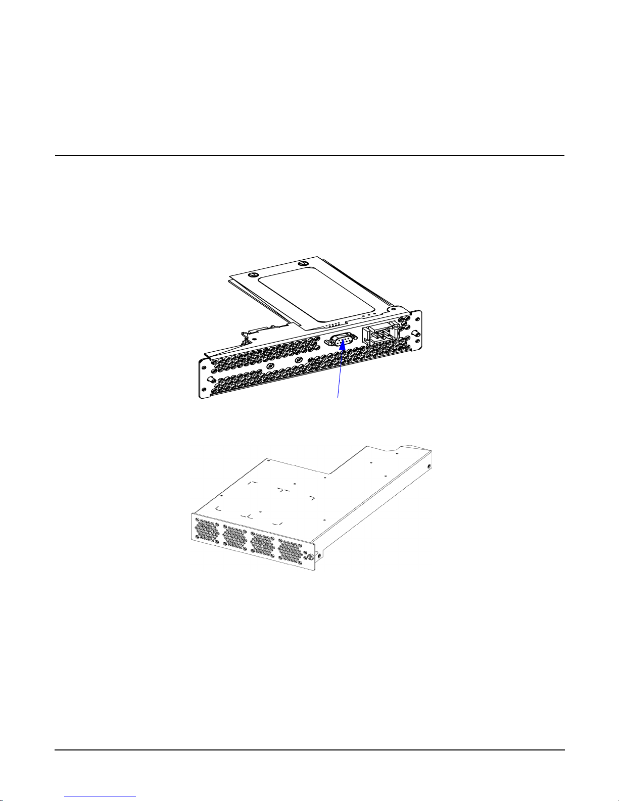
CAUTION The DB9 connector shown in Figure 0-2 marked “For Manufacturing Use Only”, was installed
for use during the manufacturing process. It cannot be used for anything else. If an RS232
-type plug is used in this receptacle, it could cause the power supply to reset, thereby losing
data being transmitted to the blades.
DO NOT USE THIS RECEPTACLE FOR ANY PURPOSE!
Figure 0-2 hp Blade Server DC Power Supply Input Module (Server Rear View)
Figure 0-3 hp Blade Server DC Power Supply Output Module (Server Front View)
Power supplies are hot swappable. Hot swap remove and replace details are found in the hp Blade Server bh
3710 Service Guide.
For Manufacturing Use Only
Page 16
Chapter 3
hp Carrier Grade Server bh3710 Power and Cooling Component Overview
DC Power Supplies
3-4
Blade Server Power Supply Connector
DC Power Input Module and Cable Connector Pinout Information
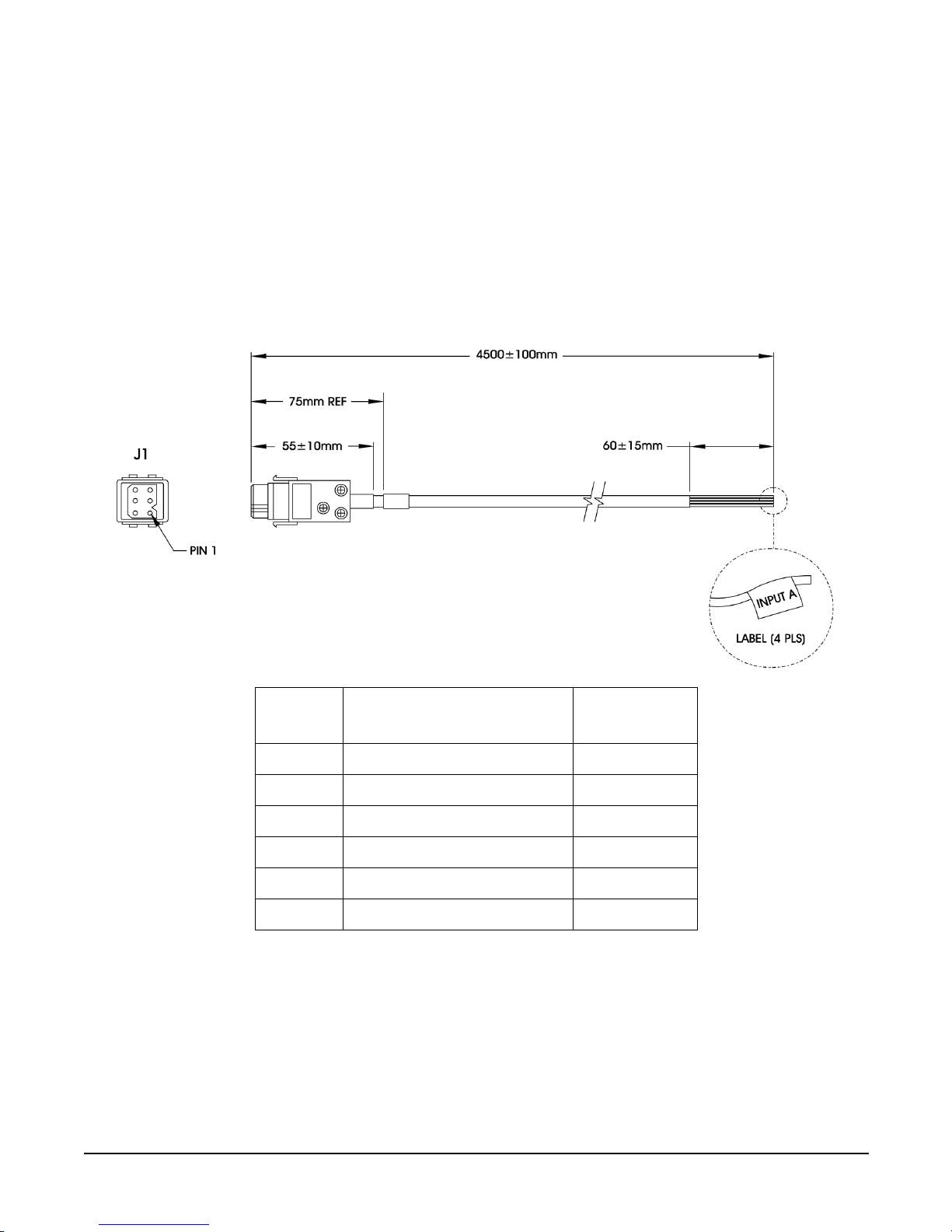
The power supply connector on the input module is a Positronics PLB06. The cable supplied for each power
supply is a 5-wire cable. All 4 wires on each cable must be connected. Two wires (red and black) are connected
to the –48VDC source and the remaining two wires (white and green) are connected to the DC return. All four
wires from the same power cord must be connected to the same power source. Each power supply filter
module may be connected to a different –48VDC source to provide power source redundancy.
Figure 0-4 DC Power Cable
Pin
Number
Function Color
1 Negative DC Supply (-48vdc) Red
2 DC Return (0vdc) White
3 Functional Earth Not Connected
4 Negative DC Supply (-48vdc) Black
5 DC Return (0vdc) Green
6 Functional Earth Not Connected
Page 17
Chapter 3
hp Carrier Grade Server bh3710 Power and Cooling Component Overview
DC Power Supplies
3-5
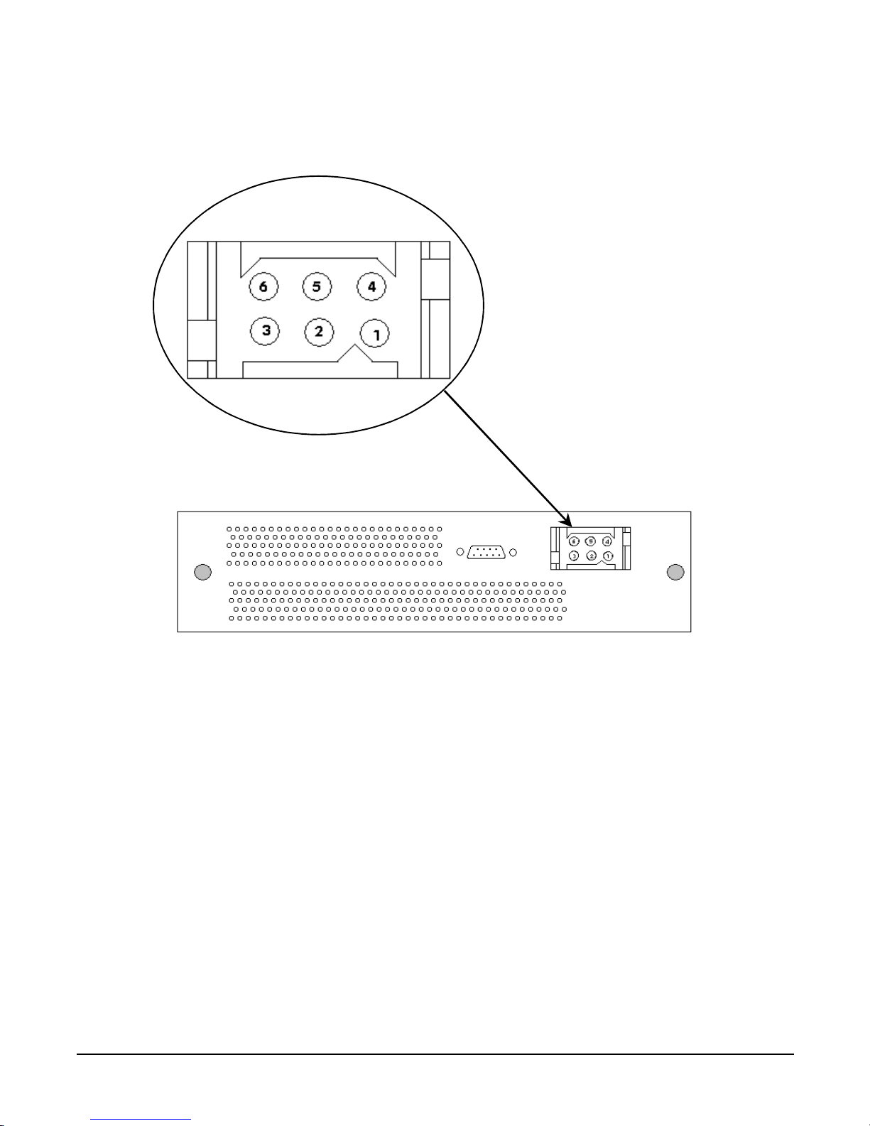
Power cable pin-out information is illustrated as follows:
Figure 0-5 DC Power Connector Pin location
Page 18

Chapter 3
hp Carrier Grade Server bh3710 Power and Cooling Component Overview
Blade Server Cooling System
3-6
Blade Server Cooling System
Both server blade and Power Supply cooling are shown in Figure 3-6 and addressed in this section.
• The CompactPCI server blades in the main chamber are cooled by the fan tray.
NOTE The N+1 fan tray assembly is an integral part of the blade server chassis and cannot be
removed or replaced in the field.
• Each PSU is cooled independently by its own set of 4 fans.
Figure 3-6 Cooling Airflow into the Blade Server
Because of the high velocity positive pressure airflow, the mechanical integrity of the system must be
maintained at all times to ensure proper cooling:
• All slot blockers must remain in place over unused slots.
• Blade installation must be completed within three minutes from removal of the slot blocker.
Any deviation from these requirements may result in the management blade shutting down the entire
system.
PS Airflow (IN)
Blade Cooling Fan Airflow (IN)
PS Air (OUT)
Blade Cooling Fan Airflow (OUT)
N+1 Fan Tray Assembly
Page 19

Chapter 4
Applying Power to the hp Blade Server bh3710
Introduction
4-1
4 Applying Power to the hp Blade Server
bh3710
Introduction
The following sections discuss both the application and removal of power to the blade server.
NOTE Before applying power to the blade server, locate the management server blade in slot F10
(server front, slot 10) and plug a console into the management Console port.
A console can be either an alpha/numeric terminal, or a desktop PC, or a laptop PC running a
VT-100 terminal emulator.
hp Blade Server Initial Power-Up
blade server power-up consists of providing power to the management blade first, then the remainder of the
server blades begin their power-up procedures.
Chassis and Management Blade Power-Up
Connect the power cords between the blade server power supplies and the DC power source. The blade server
chassis will immediately begin to power-up and the console will display power-up self test data.
Look for the slot F10 status LED. Status LEDs are located in a vertical panel on the cooling fan assembly
cover. When chassis power-up has been successfully accomplished, the management blade status LED will be
green. You can now log on to the management blade to perform management blade and bp2200 (PA) server
blade MP configuration. Refer to Chapter 5, “hp Carrier Grade Server bh3710 Server Blade Installation
Information,” on page 1for network configuration procedures.
bp2200 Server Blade Power-Up
When bp2200 server blade configuration is complete, exit the management blade configuration menu and
select, 3. exit to LINUX Shell. The console will begin to display boot/self-test data and, upon successful
completion of boot and self-test procedures, the HP-UX login prompt will be displayed. When server blade
power-up has been successfully completed, the status LED for slot F10 will be green.
The bp2200 server blade powers up and, when the green LED beside the blade slot is illuminated, it is ready
for configuration.
Page 20

Chapter 4
Applying Power to the hp Blade Server bh3710
Blade Server Power-Down
4-2
Blade Server Power-Down
Power-down procedures apply to the rp2200 and management server blades. The chassis (blade server) is
powered down only after all server blades are shut off.
Power-Down the bp2200 and Management Blades
Orderly power-down of the blade server requires that the bp2200 blade be powered-off first, then the
Management blade. The following steps apply for powering-down both systems:
Step 1. Press the red tabs in on the left and right locking levers to start power-down. When the blue
hot-swap LED illuminates, power-down is complete.
Step 2. The server blades can now be safely removed from the blade server.
CAUTION If you are going to remove either of these blades, you must complete blade removal and
replacement with either another blade of the same type or a slot blocker, within 3 minutes to
comply with cooling requirements. Failure to do so may cause loss of data when overheating
causes the blades to begin to power down.
Chassis Power-Down
The blade server is designed to run continuously. Under normal conditions, only the bp2200 and management
server blades, both of which are hot-swappable, will be powered-off and on.
• If there is time, ensure that no data is lost by performing an orderly shutdown of the server blades then
pull the plug out of each power supply (if there is more than one).
• If there is no time, however, simply pull the plug out of each power supply.
CAUTION If an orderly shutdown of the server blades isn’t performed prior to power removal, all unsaved
data located in the server blades at that time will be lost.
Page 21

Chapter 5
hp Carrier Grade Server bh3710 Server Blade Installation Information
Introduction
5-1
5 hp Carrier Grade Server bh3710 Server
Blade Installation Information
Introduction
The information provided in this chapter discusses the server blades that the blade server chassis houses. All
server blades that are ordered with the blade server are pre-installed at the factory. However, bh3710 server
blades can be installed on site, if desired.
The following sections are included in this Chapter:
•“Server Blades”
• “Management Blade”
• “bp2200 Server Blade”
• “Fibrechannel (FC) and LAN Rear Transition Module (RTM) Blade”
• “Fibre Channel (FC) Disk Carrier”.
The following section describes how to install server blades and can also be used as a guide for removal and
replacement.
• “Installing and Removing Blades”.
Page 22

Chapter 5
hp Carrier Grade Server bh3710 Server Blade Installation Information
Server Blades
5-2
Server Blades
As listed in Chapter 2, Table 2-1, the standard server blade as-shipped configuration for the blade server
includes:
NOTE Server blade slots are numbered from bottom to top on both the front (F) and rear (R). The
bottom number is 1 and the top number is 10. For example, the Management blade always goes
in slot F10. Front slots 7 and 8 are not used at this time. Rear Slots 1 through 8 are not used at
this time, also.
Additional Fibre Channel Dual Disk Carrier blades are available and are described in the, “Fibre Channel
(FC) Disk Carrier” section.
No. Blade Name Front/Rear Slot(s)
1 Management Blade Front 10 (Single wide)
1 bp2200 PA Blade Front 1 and 2 (Double wide)
1 or 2 Fibre Channel Dual Disk Carrier Blade Front 3 and 4 (default). Slots 5 and 6
are for added carrier blade.
(Double wide)
2 Fibre Channel and LAN RTM Blade Rear 9 and 10 (Single wide)
Page 23

Chapter 5
hp Carrier Grade Server bh3710 Server Blade Installation Information
Server Blades
5-3
Figure 5-1 Rear View of Chassis With Blades Installed
Page 24

Chapter 5
hp Carrier Grade Server bh3710 Server Blade Installation Information
Server Blades
5-4
Figure 5-2 Front View of Chassis With Blades Installed
The blades may be inserted only in compatible slots on the chassis. Each slot is marked with a legend
corresponding to the glyph located on the bulkhead of the blade that is to be inserted.
The identification legends, or glyphs, for each blade are indicated in the individual blade descriptions that
follow.
Display Panel Blade Status Indicators
The display panel blade status indicators are located on the blade cooling fan assembly vertical panel
(Figure 5-2). Table 5-1lists the LED indications and definitions for server blades. There are two LEDs (one
yellow, one green) for each front server blade.
Table 5-1 Display Panel Blade Status LED Definitions
LED
Indication
Meaning
Solid Green Status OK; blade is operating
Flashing Green Non-critical user action required (e.g. boot prompt
waiting for password)
Solid Yellow Fault or system crash has occurred
Flashing Yellow Power is off or operator intervention is needed
Display Panel Blade
Status Indicators
Page 25

Chapter 5
hp Carrier Grade Server bh3710 Server Blade Installation Information
Management Blade
5-5
Management Blade
Management Blade information is provided as follows:
Figure 5-3 Management Blade
Figure 5-4 Management Blade Bulkhead Label
Management Blade LED Definitions
The following list describes the LEDs found on the Management Blade.
LED Color Activity
Fault LED Amber Momentarily flashes ON then OFF at power-up.
100 and 10 Base T Status LEDs Green Solid green when working; dark when off.
LAN A/B Activity LEDs Green Random blinking to show activity
Hot Swap LED Blue Solid blue means ready for blade removal
Page 26

Chapter 5
hp Carrier Grade Server bh3710 Server Blade Installation Information
Management Blade
5-6
The Management blade (previously called Server Management Card (SMC)) contains all the logic necessary
to manage the blade server system remotely. The Management blade must reside in slot F10 (Front 10). Both
the blade server chassis and the blade are identified with a sticker containing a square glyph, as shown in
below.
Figure 5-5 Identification Legend Marking
Management Blade Configuration
The Management Blade IP address has been set to the factory default.
NOTE The factory default address is:
127.0.0.1
A local console is required to perform the initial configuration. An RS-232 port is provided on the
Management Blade for this local console. The terminal type for the local console must be a VT100 emulation.
Follow the steps listed below to configure the Management Blade.
Configuring the Management Blade
The following sections include assumptions that are made and requirements to be fulfilled prior to beginning
the configuration procedure.
Pre-Configuration Assumptions.
The procedures that follow assume that:
1. The bh3710 blade server has been unpacked,
2. The blade server has been mounted in a rack,
3. Any optional blades have been installed in the blade server chassis
4. Power is applied to the blade server.
LAN Cabling Requirements.
Begin cabling as follows:
Step 1. Install management network cable to the Management LAN RJ-45 port of the Fibrechannel and
LAN Rear Transition Module. (refer to the “Fibrechannel (FC) and LAN Rear Transition Module
(RTM) Blade” section in this Chapter for LAN connectivity to the blade server).
Step 2. Connect the terminal console RS232 serial cable to the Management Blade RS232 serial port.
Step 3. Connect the terminal console power cable to a power source.
Page 27

Chapter 5
hp Carrier Grade Server bh3710 Server Blade Installation Information
Management Blade
5-7
Configuration Procedures.
Power on the Console. The Management Blade boot sequence will display, followed by a login prompt.
Management Blade Configuration. Follow the steps listed below to configure the Management Blade.
Step 1. Log in as root with the password hpblade!.
Step 2. Select the Configuration Menu from the Management Blade main menu and press
Enter to begin.
Step 3. Select the Quick Setup option.
Step 4. Select the Slot 10 Management Blade option.
Step 5. Tab to the IP Address and enter the value.
Step 6. Select and enter a Host name.
Step 7. Tab to the Gateway Address and enter the value.
Step 8. Tab to Subnet Mask and enter the value.
Step 9. If desired, Tab to and enter a Domain Name (optional).
Step 10. If desired, Tab to and enter a DNS address (optional).
Step 11. Save and exit the configuration.
Step 12. Return to the Quick Setup menu for Management Processor configuration procedures listed in the
following section.
The Management Blade can now be accessed remotely via the LAN.
Page 28

Chapter 5
hp Carrier Grade Server bh3710 Server Blade Installation Information
bp2200 Server Blade
5-8
bp2200 Server Blade
Figure 5-6 bp2200 Server Blade
The bp2200 server blade (also called the PA-RISC or PA blade), comes factory installed, and runs the
pre-configured HP-UX Operating System stored on the factory-installed Fibre Channel Disk. The bp2200
server blade contains the System Processor Unit (SPU), the Management Processor (MP) and Memory
DIMMs. The bp2200 server blade is double-wide and resides in slots 1 and 2.
Figure 5-7 bp2200 Blade Bulkhead Label
The identification glyph for the bp2200 server blade is illustrated in Figure 5-8.
Figure 5-8 bp2200 Identification Legend Marking
Page 29

Chapter 5
hp Carrier Grade Server bh3710 Server Blade Installation Information
bp2200 Server Blade
5-9
GSP Reset and Transfer of Control (TOC) Buttons
The GSP (now called MP) and TOC reset buttons, located on the bp2200 bulkhead, are described below:
CAUTION DO NOT press the TOC button unless the bp2200 blade is hung. If you press the TOC button,
the blade will immediately shut down. Failure to observe this precaution could result in loss of
customer data.
• Pressing the GSP (MP) reset button reboots the MP.
• Pressing the TOC button causes the bp2200 blade to shut down and a memory dump to occur.
bp2200 Server Blade LED Definitions
The following list describes the LEDs found on the bp2200 server blade bulkhead.
NOTE See the bp2200 chapter of the hp Carrier Grade Server bh3710 Service Guide for Attention and
Fault LED definitions.
LED Color Description
LAN A and B LEDs Green Flashes intermittently when in use.
Fibre Channel A and B LEDs Green Flashes intermittently when in use.
Hot Swap LED Blue Solid blue when ready for Hot Swap; flashes
once when powering down or disconnecting
from backplane.
Attn:/Fault LED Amber Solid amber is a fault; flashing is operator
intervention/attention required.
Run LED Green Flashes once when power is applied; flashes
when the server is booting HP-UX; solid
green when OS is booted and server blade is
running.
Page 30

Chapter 5
hp Carrier Grade Server bh3710 Server Blade Installation Information
bp2200 Server Blade
5-10
bp2200 Management Processor (MP) Configuration
Configuring the MP
The following sections include assumptions that are made and requirements to be fulfilled prior to beginning
the configuration procedure.
Pre-Configuration Assumptions.
The procedures that follow assume that:
1. The bh3710 blade server has been unpacked,
2. The blade server has been mounted in a rack,
3. Any optional blades have been installed in the blade server chassis
4. Power is applied to the blade server, and
5. The Management Blade is operating.
LAN Cabling Requirements.
Once the Management Blade is operating, install payload network and management network cables to the
LAN Management blades (refer to the “Fibrechannel (FC) and LAN Rear Transition Module (RTM) Blade”
section in this Chapter for LAN connectivity to the blade server).
Configuration Procedures.
Power on the Console. The Management Blade boot sequence will display, followed by a login prompt.
Configure the Management Blade first, then the Management Processor (MP), (formerly called the Guardian
Service Processor (GSP)) resident on the bp2200 server blade. Proceed as follows:
Page 31

Chapter 5
hp Carrier Grade Server bh3710 Server Blade Installation Information
bp2200 Server Blade
5-11
Management Blade Configuration. If the Management blade has not been configured at this point,
return to the Management Blade section of this Chapter for configuration procedures.
Management Processor Network Parameters Configuration. Follow the steps listed below to
configure the Management Processor.
Step 1. From the Management Blade Quick Setup Screen, select slot one to configure MP network
parameters.
Step 2. Tab to the IP Address and enter the value.
Step 3. Select and enter a Host name.
Step 4. Tab to the Gateway Address and enter the value.
Step 5. Tab to Subnet Mask and enter the value.
Step 6. If desired, tab to and enter a Domain Name (optional).
Step 7. If desired, tab to and enter a DNS address (optional).
Step 8. Save and exit the configuration.
The MP can now be accessed remotely via the LAN.
Access the MP Console.
CAUTION The factory default MP configuration allows access without entering login or password data. To
ensure security, configure the MP root/administrator username and password with the SO
command, as soon as the MP has been accessed. Failure to observe this precaution may result
in compromised system security.
Refer to the hp Carrier Grade Server bp3710 Service Manual for information about the MP.
Once the IP Address is set, a remote host is used to TelNet into the MP. Plug a LAN cable into the
Management LAN RJ-45 connector. The Management LAN port on the blade server chassis is the extreme
right RJ-45 connector on either of the two FC and LAN RTM Blades that are plugged in slots 9 and 10 at the
rear of the blade server. When the connection is complete, you can TelNet to the IP address of the MP and it
will respond. The following login prompt will be displayed:
Service Processor login:
Press Enter.
The console will display:
Service Processor password:
Press Enter.
The console will display general identification information. Press Enter.
The console will display:
[Read only - use ^Ecf for console write access.]
After the message is displayed, press the
Ctrl key, then type Ecf (“Ecf ” is case-sensitive. Capitalize the E, only)
and press Enter.
The console will display:[ bumped user -]. Press Enter. The console will then display the GSP> prompt.
Type the SO command and type the new root username and password.
Page 32

Chapter 5
hp Carrier Grade Server bh3710 Server Blade Installation Information
bp2200 Server Blade
5-12
Boot Procedures
The following sections describe the procedure for booting the Boot Console Handler, booting to the HP-UX
prompt, and rebooting to HP-UX to restart the system.
Boot Console Handler (BCH) Boot Procedures
The blade will boot to BCH upon insertion in the chassis. When the boot process is completed (in
approximately one to five minutes) the BCH main menu will be displayed as shown below:
----Main Menu ----------------------------------------------------
Command Description
------------ --------------
BOot [PRI|ALT|<path>] Boot from specified path
PAth [PRI|ALT] [<path>] Display or modify a path
SEArch [DIsplay|IPL] [<path>] Search for boot devices
COnfiguration menu Displays or sets boot values
INformation menu Displays hardware information
SERvice menu Displays service commands
DIsplay Redisplay the current menu
HElp [<menu>|<command>] Display help for menu or command
RESET Restart the system
----
Main Menu: Enter command or menu
Boot to the HP-UX Prompt
Start the boot process by using the factory default boot path. Type, BO PRI, at the BCH main menu prompt
and press
ENTER.
NOTE Booting the system to an HP-UX login prompt from the BCH main menu will take five minutes
or longer depending on your software and hardware configuration.
Once the system reaches the HP-UX login prompt, the following information will be displayed on the console
screen:
Generic SysName [HP Release B.11.11] (see /etc/issue)
Console Login:
Page 33

Chapter 5
hp Carrier Grade Server bh3710 Server Blade Installation Information
bp2200 Server Blade
5-13
Rebooting to the HP-UX Prompt
HP-UX can be restarted as shown in the following steps:
Step 1. Telnet to the MP IP.
Step 2. Log in to the MP using the assigned login name and password.
Step 3. Press
Enter then type Ecf (“Ecf ” is case-sensitive. Capitalize the E, only) and press Enter for write
access.
Step 4. When the MP prompt appears, type rs to reset the server and start a system reboot.
CAUTION Do not use the reset command (rs) while the HP-UX Operating System is running. Use the rs
command only after an orderly operating system shutdown has been accomplished with the
/etc/shutdown -h entry or if the server blade will not respond to console commands. Failure
to observe this precaution may cause file system corruption.
Page 34

Chapter 5
hp Carrier Grade Server bh3710 Server Blade Installation Information
Fibrechannel (FC) and LAN Rear Transition Module (RTM) Blade
5-14
Fibrechannel (FC) and LAN Rear Transition Module (RTM) Blade
FC and LAN RTM blade information is provided in the following sections.
Figure 5-9 FC and LAN RTM Blade
Figure 5-10 FC and LAN RTM Blade Bulkhead Label
The identification glyph for the Fibrechannel and LAN RTM is illustrated in the figure below.
Figure 5-11 Fibrechannel and LAN RTM Identification Legend Marking
Page 35

Chapter 5
hp Carrier Grade Server bh3710 Server Blade Installation Information
Fibrechannel (FC) and LAN Rear Transition Module (RTM) Blade
5-15
FC and LAN RTM LED Definitions
The following list describes the LEDs found on the FC and LAN RTM blade:
FC and LAN RTM Ports
The FC and LAN RTM blade provides the following ports:
• One LAN port for a server blade
• One LAN port for the Management Blade and GSP
• One serial port for the Management Blade
• One Fibre Channel port bypass port.
NOTE Shielded Category 5 LAN cables are required to meet FCC noise emission requirements.
LAN Connectivity to the FC and LAN RTM Ports
Network cabling can be structured two ways, depending on whether or not separate payload and management
LAN segments are available at the site.
• Put the bp2200 payload and the Management blade on separate LAN segments.
• Put the bp2200 payload and the Management blade on the same LAN segment.
The FC and LAN RTM is designed to provide secure access to hardware data, monitoring, and event
management while leaving the payload LAN (customer LAN) for individual customer communications. This
design isolates sensitive customer data on the payload LAN from the blade server monitoring data on the
Management LAN.
NOTE Connecting the bp2200 payload LAN and the Management LAN to separate LAN segments is
encouraged to separate sensitive customer data from management data.
LAN Connectivity Pre-installation Preparation
During the planning phase of installation, allocate up to four IP addresses to complete LAN connectivity:
• Up to three IP addresses for the bp2200.
— Up to two addresses for blade hosting (one address for LAN A and one for LAN B, if desired), and
— One address for the MP (formerly GSP).
• One IP address for the Management Blade (SMC).
LED Color Description
Management Console LED
Green Off when not plugged in; solid when plugged in.
FC Link LED
LAN B LED
LAN A LED
Page 36

Chapter 5
hp Carrier Grade Server bh3710 Server Blade Installation Information
Fibrechannel (FC) and LAN Rear Transition Module (RTM) Blade
5-16
Figure 5-12 bh3710 Chassis (Rear View)
If the Payload LAN and the Management LAN are on separate LAN segments:
Step 1. In rear slot 9: Plug payload LAN (A) into RJ-45 port A (Center port) on the FC and LAN RTM
blade.
Step 2. In rear slot 10: Plug the Management LAN into the RJ-45 Management LAN Console (rightmost
port) on the FC and LAN RTM blade.
CAUTION Either Management LAN port (slot 9 or 10) may be used. However, do not use both
ports on the same switch. Failure to observe this precaution will cause network
malfunction.
Step 3. In rear slot 10: Plug a Payload LAN (B) into the RJ-45 port B (Left port) on the FC and LAN RTM
blade.
NOTE Only the LAN A port functions on slot 9. Only the LAN B port functions on slot 10.
Slot 10
Slot 9
LAN A
Mgmt
LAN
Serial
FC Loop B
Serial FC Loop A
LAN B
LAN B
LAN A
Mgmt
LAN
C o n n e ct to s ite
Payload LAN-A
C o nn e ct to s ite
Payload LAN-B
C o nn e ct to s ite
Management LAN
Page 37

Chapter 5
hp Carrier Grade Server bh3710 Server Blade Installation Information
Fibrechannel (FC) and LAN Rear Transition Module (RTM) Blade
5-17
If the Payload LAN and the Management LAN are on the same LAN segment:
Step 1. In rear slot 10: Plug the Payload (A)/Management LAN into the RJ-45 Management LAN Console
port (the rightmost port) on the FC and LAN RTM blade.
Step 2. In rear slot 10: Plug the Payload (B) LAN into RJ-45 port B (the leftmost port) on the FC and LAN
RTM blade.
Step 3. In rear slot 9: Plug a LAN cable into the RJ-45 Management LAN Console port (the rightmost port)
and into RJ-45 port A (the Center port) on the FC and LAN RTM blade.
NOTE Only the LAN A port functions on slot 9. Only the LAN B port functions on slot 10.
Slot 10
Slot 9
LAN A
Mgmt
LAN
Serial
FC Loop B
Serial FC Loop A
LAN B
LAN B
LAN A
Mgmt
LAN
Co n nect to site
Payload LAN-B
Co n nect to s ite P ay loa d
LAN-A/Mgm t LAN
Connect cable from
Payload LAN-A to
Management LAN
Page 38

Chapter 5
hp Carrier Grade Server bh3710 Server Blade Installation Information
Fibre Channel (FC) Disk Carrier
5-18
Fibre Channel (FC) Disk Carrier
FC Disk Carrier blade information is provided in the following sections.
Figure 5-13 FC Disk Carrier
Server blade storage capacity can be added by using the FC disk carrier with one or two drives installed. The
carrier and drives utilize two slots and are normally installed in slots 3 and 4 (factory default), and 5 and 6.
Slots that will accommodate FC disk carriers are identified by the glyph shown below:
NOTE If the FC Disk Carrier containing the bootable disk is moved to a different pair of slots, the
system will not boot to HP-UX. The system must either be reconfigured to identify the new slot
location (see Appendix A), or the FC Disk Carrier must be returned to its original pair of slots.
Figure 5-14 FC Disk Carrier Legend Marking
Figure 5-15 FC Disk Drive Bulkhead Label
Page 39

Chapter 5
hp Carrier Grade Server bh3710 Server Blade Installation Information
Fibre Channel (FC) Disk Carrier
5-19
NOTE LEDs are only found on the disk drives contained within the disk carrier. There are no LEDs
for the disk carrier.
FC Disk Drive LED Definitions
The following list describes the LEDs found on the FC Disk Drive.
LED Color Description
LAN A LED
Amber LED lights at power on.
LAN B LED
Activity LED Green Flashes at power on; steady during operation
Fault LED Red Light is steady when there is a fault, otherwise LED is out.
Page 40

Chapter 5
hp Carrier Grade Server bh3710 Server Blade Installation Information
Installing and Removing Blades
5-20
Installing and Removing Blades
There are two types of blades used in the rp3710 Blade Server:
• Blades that are held in place on the chassis by locking levers. This type of blade has a blue LED that
lights to indicate when it is shut down and ready to be removed.
• Carrier blades that can contain up to two components, such as Fibre Channel disks. The components are
held in the Carrier blade by screws and each has its own handle. Carrier Blades are held in place on the
chassis by screws and are installed and removed by grasping the component handles.
Blade server cooling requirements dictate that all slots be closed, either by the server blades that are
installed, or by slot blockers. Slot blockers come in two sizes:
• Full size, 6U x 160 mm, used in the front slots and
• Half size, 6U x 80 mm, used in the rear slots.
Blades are installed from either the front or rear of the chassis. However, the blade type must match the slot
type and size. Both types and sizes are identified with stickers as described in the previous section.
The best way to ensure blade replacement within the requisite time window is to plan your installation in
advance:
• Ensure that you are properly grounded before commencing.
• Have the blade ready for installation and near the blade server.
• If you are removing a blade, have a slot blocker ready.
• Have a number 1 Phillips screwdriver available.
• Familiarize yourself with the operation before you begin.
Following the planning instructions outlined above, prepare your equipment and select the empty slot(s)
compatible with the type of blade you wish to install. Then, follow the steps listed below.
Page 41

Chapter 5
hp Carrier Grade Server bh3710 Server Blade Installation Information
Installing and Removing Blades
5-21
Removing and Installing Slot Blockers
Figure 5-16 Slot Blocker
Slot blockers are installed in those empty slots in which there are no blades to maintain airflow integrity in
the blade server chassis. Their installation is required to keep the resident blades cool during operation.
CAUTION You must complete both slot blocker removal and server blade installation/replacement within
3 minutes to comply with cooling requirements. Failure to comply with this requirement may
cause loss of data when the installed blades exceed maximum temperature and begin to power
down.
Remove the Slot Blocker
Remove Slot Blockers according to the steps listed below:
Step 1. Loosen the captive screws on the slot blocker, shown in Figure 5-16.
Step 2. Remove the slot blocker from the chassis. If the replacement blade uses two slots, remove the
second slot blocker.
Step 3. Place the slot blocker in a storage area where it can be easily located when needed next.
Install the Slot Blocker
Install Slot blockers according to the steps listed below:
Step 1. Retrieve the slot blocker from its stored location.
Step 2. Carefully align the slot blocker in the card guides and slide it into the chassis.
Step 3. Tighten the captive screws.
Captive Screws
Page 42

Chapter 5
hp Carrier Grade Server bh3710 Server Blade Installation Information
Installing and Removing Blades
5-22
Installing and Removing Blades With Locking Levers
Procedures for the installation and Removal of server blades with Locking Levers are listed and illustrated
below.
Installing Blades With Locking Levers
Install the server blade according to the following steps:
Step 1. Grasp the two locking levers and lift the blade from its antistatic surface.
Step 2. If the locking levers are locked (levers do not open freely), press the red tabs on each locking lever
in to unlock them. The open locking levers will then swing out with latches at right angles to the
blade bulkhead.
Step 3. Holding the blade by the locking levers, align it with the card guides inside the open slot and
carefully push the blade fully into the chassis as shown in Figure 5-17.
CAUTION Ensure that the locking levers are unlocked before seating the blade in the chassis
and closing the locking levers. Failure to observe this precaution may cause the red
tabs to break, thereby compromising air circulation.
Figure 5-17 Align Blades With Card Guides and Push Into Chassis
Step 4. When the blade is fully inserted, ensure that the hooks on the locking levers engage the chassis at
the left and right edges of the blade slot.
Step 5. Once the hooks engage the chassis, grasp the two locking levers and simultaneously push them
toward each other to securely seat the blade in the connector on the backplane, as shown in the
Figure 5-18. It may take additional effort to push the board into final seating, because it must mate
with several connectors on the backplane. The red tabs on the inside of each locking lever will
automatically click into position. Figure 5-18, shown below, illustrates the hooks engaging the
chassis and the direction of force needed to close the locking levers.
Page 43

Chapter 5
hp Carrier Grade Server bh3710 Server Blade Installation Information
Installing and Removing Blades
5-23
NOTE The blue LED will briefly illuminated when power is reestablished as the blade
mates with the backplane connectors.
Figure 5-18 Insert the Blade
Step 6. Tighten the small screws in each locking lever (as shown in Figure 5-19). This completes the
installation.
Figure 5-19 Tighten the Locking Screws
Page 44

Chapter 5
hp Carrier Grade Server bh3710 Server Blade Installation Information
Installing and Removing Blades
5-24
Removing Blades With Locking Levers
Removing Server Blades with locking levers can be accomplished in either of two ways:
• Entering the /etc/shutdown -h command at the console to bring the blade to an orderly halt prior to
pushing the red tabs toward the latches is the recommended way to shut down the blade.
• Blades with locking levers are hot swappable and can be removed without an orderly shut down.
The steps listed below detail the hot swap method of blade removal.
Figure 5-20 Releasing Locking Levers
Step 1. Press the red tabs, located on the inside of both left and right locking levers, inward, toward the
latches. The latches will partially snap out. This action begins the blade hot swap shut-down
procedure. Figure 5-20 illustrates the location of the red tabs.
The blade will now enter its hot swap shutdown routine. Do NOT attempt to remove the blade at
this time or data may be lost. When the blade is completely shut down, a blue LED on the right side
of the blade bulkhead will illuminate to indicate that the blade is ready to be removed. It can take
up to two minutes for the blue LED to illuminate.
Step 2. While waiting for the blue LED to illuminate, loosen the screws located in the left locking lever and
right locking levers as shown in Figure 5-21. Do NOT attempt to remove the blade at this time.
NOTE The blue LED will remain illuminated until power is removed by loosening the blade
from the backplane
Page 45

Chapter 5
hp Carrier Grade Server bh3710 Server Blade Installation Information
Installing and Removing Blades
5-25
Figure 5-21 Loosen Locking Screws
Step 3. To release the blade from the backplane, apply pressure to the left locking lever and to the right
locking lever at the same time. You should be able to “snap” the levers away from each other and
unlatch the blade from the left and right edges of the blade slot. Figure 5-22 illustrates this step.
Figure 5-22 Releasing Locking Levers
Page 46

Chapter 5
hp Carrier Grade Server bh3710 Server Blade Installation Information
Installing and Removing Blades
5-26
Step 4. Still grasping the locking levers, firmly pull the blade from the chassis (Figure 5-23). The blade
connectors fit snugly in the backplane and it may take additional effort to disengage the blade from
the backplane.
Figure 5-23 Pull Blade From Chassis
Step 5. Extract the blade completely from the chassis and carefully place it on an antistatic-protected area.
This concludes blade removal.
Page 47

Chapter 5
hp Carrier Grade Server bh3710 Server Blade Installation Information
Installing and Removing Blades
5-27
Installing and Removing Carrier Blades
Procedures to be used for the installation and removal of Carrier Blades are listed below.
CAUTION You must complete removal/installation steps within 3 minutes, or install slot blockers, to
comply with cooling requirements. Failure to satisfy this requirement may cause loss of data
when the remaining blades begin to power down.
Installing the Carrier Blade
This procedure is used for either one or two-slot blade installation.
NOTE Carrier blades do not have locking levers or handles. Each Fibre Channel disk that is mounted
in the carrier blade has a handle that is used to mount the disk in the carrier. The disk handle
is then used to insert the carrier blade into the blade server.
A single disk may be ordered for the carrier, even though each carrier holds two disks.
If the carrier is ordered with only one disk, ensure that a cover is used on the bulkhead to seal
the unused disk space so that air circulation integrity is maintained.
One and two disk carrier blades are installed and removed the same way. The steps listed below describe the
two-disk configuration.
Step 1. Grasp the blade by the handles (shown in Figure 5-24) and align it with the card guides inside the
open slot.
Figure 5-24 Two-Handled Blade
Step 2. Carefully push the blade into the chassis until it mates with the backplane.
Step 3. Tighten the captive screws to securely seat the blade in the connector on the backplane. This
completes blade installation.
Page 48

Chapter 5
hp Carrier Grade Server bh3710 Server Blade Installation Information
Installing and Removing Blades
5-28
Removing the Carrier Blade
CAUTION Fibre Channel disks have no hot swap LED to indicate when they can be removed. Remove the
disk carrier only under the following conditions:
• The bp2200 hot swap blue light is illuminated, indicating that the bp2200 is no longer
accessing the Fibre Channel disks, or
• the disk has been unmounted at the OS level.
Failure to observe this precaution may result in loss of disk data.
Remove Carrier Blades according to the following steps:
Step 1. Loosen the captive screws at each side and unseat the blade from the backplane.
Figure 5-25 FC Disk Carrier Blade
Step 2. Grasp the blade by the handles and carefully pull the blade all the way out of the chassis.
Step 3. Place the blade in an antistatic bag and remove it to a safe place. This concludes blade removal.
Page 49

Chapter 6
Communication with the hp Carrier Grade Blade Server bh3710
Introduction
6-1
6 Communication with the hp Carrier Grade
Blade Server bh3710
Introduction
Local management communications with the blade server takes place via a local console connection to the
Management blade. See Chapter 3 of this manual and the hp bh3710 Carrier Grade Blade Server Service
Guide for configuration details.
Once the Management blade LAN configuration is set, further configuration can be performed with LAN
TelNet sessions, which are used to check configuration settings, load operating systems (see Remote
Installation of Operating Systems below), and to troubleshoot using the Support Tool Manager diagnostic
tool.
CAUTION The factory default MP configuration allows access to the bp2200 Server blade without
requiring a login name or password. Establish security immediately by configuring MP
usernames and passwords by using the SO command at the MP console as soon as
communication is established. Failure to heed this precaution may result in unauthorized
access and loss of customer data.
Remote Installation of Operating Systems
The blade server is shipped with the HP-UX operating system installed and located on the Fibre Channel
disk for the bp2200 server blade primary boot path.
The Support Tool Manager
The Support Tool Manager is a diagnostic program supplied with the bp2200 Server Blade to perform
troubleshooting and allow isolation of faults to a particular Field Replaceable Unit (FRU).
The Support Tool Manager runs on a PC or laptop under Windows, and communicates with the bp2200 Server
Blade through the Management Processor (MP), via the Management LAN, or through the Fibre Channel and
LAN RTM circuit through the customer LAN.
Complete documentation is supplied on the Support Tool Manager CD and further information is available on
the following web site: http://www.docs.hp.com/index.html then select diagnostics.
Page 50

Chapter 6
Communication with the hp Carrier Grade Blade Server bh3710
Remote Installation of Operating Systems
6-2
Page 51

Chapter 7
Specifications for the hp Carrier Grade Server bh3710
Introduction
7-1
7 Specifications for the hp Carrier Grade
Server bh3710
Introduction
This chapter lists the environmental specifications for the Blade Server.
Description Specification
Dimensions (H, W, D) 10.5 x 17 x 14 in (26.25 x 42.50 x 35.00 cm)
Weight (configured) Approximately 51 lbs (23.4 Kg)
Input Power
•Operational
• Recommended
-40 to -70 VDC (Margin included)
-48 to –60 VDC
Temperature
•Operational
•Non-Operational
+5 to +35C. (Goal: derate 4C/1000m above 1500m altitude)
(Commit: derate 2C/1000m above sea level)
Recommended:+20 to +25C
-40 to +70C
Humidity
•Operational:
• Recommended
15% to 80% RH non-condensing @35C
40% to 60% RH non-condensing
Maximum Altitude
•Operational
•Non-Operational
3000 meters above sea level
4500 meters above sea level
Acoustics
• Sound Power
54.0 dBA Bels LwA (not to exceed 7.5 Bels)
Page 52

Chapter 7
Specifications for the hp Carrier Grade Server bh3710
Introduction
7-2
Page 53

Appendix A
LVM Boot Device Hardware Path Change for the hp Carrier Grade Server bh3710
A-1
A LVM Boot Device Hardware PathChange for
the hp Carrier Grade Server bh3710
Page 54

Appendix A
LVM Boot Device Hardware Path Change for the hp Carrier Grade Server bh3710
A-2
Page 55

3
Index
Numerics
18GB Fiber Channel Disk
, 2-2
256 MB DIMM, 2-2
A
Access the MP Console
, 5-10
Acoustics, 7-1
Altitude, 7-1
Audience Assumptions, 1-1
B
Blade Server Chassis
, 2-2
Blade Server Cooling System, 3-6
Blade Server Power-Down, 4-2
Boot Console Handler Boot Procedures, 5-11
Boot Procedures, 5-11
bp2200 Blade (2 slot), 2-2
bp2200 Server Blade, 5-7
bp2200 Server Blade LED Definitions, 5-8
C
Chassis and Management Blade Power-Up
, 4-1
Chassis Power-Down, 4-2
Compact PCI, 1-1
Configuration Procedures, 5-6, 5-9
Configuring the MP, 5-9
D
DB9 connector
, 3-3
DC Power Input Module and Cable Connector Pinout
Information
, 3-4
DC Power Supplies, 3-2
DIMM Filler, 2-2
E
Electrostatic Discharge (ESD)
, 2-1
F
F/C Disk Carriers, 5-2
FC and LAN RTM LED Definitions, 5-14
FC and LAN RTM Ports, 5-14
FC disk carrier, 5-17
FC Disk Drive LED Definitions, 5-18
Fibre Channel (FC) and LAN RTM Blade, 2-2
Fibre Channel (FC) Disk Carrier, 5-17
Fibrechannel (FC) and LAN Rear Transition Module
(RTM) Blade, 5-13
G
Grounding
, 3-3
GSP Reset and Transfer of Control (TOC) Buttons,
5-8
H
hp Blade Server Initial Power-up
, 4-1
Humidity, 7-1
I
Installation Guide Contents, 1-1
Install the Slot Blocker, 5-20
Installing and Removing blades, 5-19
Installing and Removing Blades With Locking
Levers
, 5-21
Installing and Removing Carrier Blades, 5-26
Installing the bh3710 Blade Server in a Rack, 2-2
Installing The Carrier Blade, 5-26
L
LAN Cabling Requirements
, 5-5. 5-9
LAN Conectivity Preinstallation Preparation, 5-14
LAN Conectivity to the FC and LAN RTM Ports, 5-14
M
Management Blade
, 5-4
Management Blade Configuration, 5-5, 5-6, 5-10
Management Blade LED Definitions, 5-4
Management Processor Network Parameters
Configuration, 5-10
N
Network Equipment Building Systems (NEBS)
Compliance
, 1-1
P
Power-Down the bp2200 and Management Blades
,
4-2
Pre-Configuration Assumptions, 5-5, 5-9
R
Remote Installation of Operating Systems
, 6-1
Remove the Slot Blocker, 5-20
Removing and Installing Slot Blockers, 5-20
Removing Blades With Locking Levers, 5-23
Removing the Carrier Blade, 5-27
RS232, 3-3
S
Server Blade Power-Up
, 4-1
Server Blades, 5-2
Server Management Blade, 2-2
Site Preparation Guide, 2-1
Site Preperation, 2-1
Specifications for the hp Carrier Grade Server
bh3710
, 7-1
Support Tool Manager, 6-1
T
Temperature
, 7-1
U
Unpacking the Blade Server
, 2-1
W
Weight, 7-1
 Loading...