

Page 1
Service manual: Troubleshooting
HP Color LaserJet Enterprise M652, M653
HP Color LaserJet Managed E65050, E65060
HP Color LaserJet Managed E65150, E65160
HP Color LaserJet Enterprise MFP M681, M682
HP Color LaserJet Managed MFP E67550, E67560
HP Color LaserJet Managed MFP E67650, E67660
www.hp.com/videos/LaserJet
www.hp.com/support/colorlj652
www.hp.com/support/colorlj653
www.hp.com/support/ljE65050
www.hp.com/support/ljE65060
www.hp.com/support/colorljE65150
www.hp.com/support/colorljE65160
www.hp.com/support/colorljM681MFP
www.hp.com/support/colorljM682MFP
www.hp.com/support/ljE67550MFP
www.hp.com/support/ljE67560MFP
www.hp.com/support/colorljE67650MFP
www.hp.com/support/colorljE67660MFP
Page 2

Page 3

HP Color LaserJet Enterprise M652, M653
HP Color LaserJet Managed E65050, E65060
HP Color LaserJet Managed E65150, E65160
HP Color LaserJet Enterprise MFP M681, M682
HP Color LaserJet Managed MFP E67550, E67560
HP Color LaserJet Managed MFP E67650, E67660
Service manual: Troubleshooting
Page 4

Copyright and License
Trademark Credits
© Copyright 2019 HP Development Company,
L.P.
Reproduction, adaptation, or translation without
prior written permission is prohibited, except as
allowed under the copyright laws.
The information contained herein is subject to
change without notice.
The only warranties for HP products and
services are set forth in the express warranty
statements accompanying such products and
services. Nothing herein should be construed as
constituting an additional warranty. HP shall not
be liable for technical or editorial errors or
omissions contained herein.
Edition 3, 5/2019
Microsoft®, Windows®, Windows® XP, and
Windows Vista® are U.S. registered trademarks
of Microsoft Corporation.
Page 5

Conventions used in this guide
TIP: Helpful hints or shortcuts.
NOTE: Information that explains a concept or how to complete a task.
Reinstallation tip: Reinstallation helpful hints, shortcuts, or considerations.
IMPORTANT: Information that help the user to avoid potential printer error conditions.
CAUTION: Procedures that the user must follow to avoid losing data or damaging the printer.
WARNING! Procedures that the user must follow to avoid personal injury, catastrophic loss of data, or extensive
damage to the printer.
ENWW iii
Page 6

iv Conventions used in this guide ENWW
Page 7

HP service and support
Learn about HP access to additional service and support information.
Additional service and support for channel partners
Channel partners, go to partner.hp.com, and then use the steps below to access the HP Web-based Interactive
Search Engine (WISE).
Access WISE for Channel partners
1. Select Services & Support, and then select Services Delivery.
2. Select Technical Support, and then select Technical Documentation.
Find information about the following topics
● Service manuals
● Service advisories
● Up-to-date control panel message (CPMD) troubleshooting
● Install and congure
● Printer specications
● Solutions for printer issues and emerging issues
● Remove and replace part instructions and videos
● Warranty and regulatory information
Additional service and support for HP internal personnel
HP internal personnel, go to one of the following Web-based Interactive Search Engine (WISE) sites:
Americas (AMS)
– https://support.hp.com/wise/home/ams-enWISE - English
– https://support.hp.com/wise/home/ams-esWISE - Spanish
– https://support.hp.com/wise/home/ams-ptWISE - Portuguese
– https://support.hp.com/wise/home/ams-frWISE - French
Asia Pacic / Japan (APJ)
○ https://support.hp.com/wise/home/apj-enWISE - English
○ https://support.hp.com/wise/home/apj-jaWISE - Japanese
○ https://support.hp.com/wise/home/apj-koWISE - Korean
○ https://support.hp.com/wise/home/apj-zh-HansWISE - Chinese (simplied)
ENWW v
Page 8

○ https://support.hp.com/wise/home/apj-zh-HantWISE - Chinese (traditional)
○ https://support.hp.com/wise/home/apj-thWISE - Thai
Europe / Middle East / Africa (EMEA)
– https://support.hp.com/wise/home/emea-enWISE - English
vi HP service and support ENWW
Page 9

Table of contents
1 Theory of operation .................................................................................................................................................................................. 1
HP service and support ........................................................................................................................................................... 2
Additional service and support for channel partners .................................................................................... 2
Additional service and support for HP internal personnel ............................................................................ 2
Basic operation ......................................................................................................................................................................... 4
Sequence of operation ........................................................................................................................................ 5
Formatter-control system ...................................................................................................................................................... 7
Sleep mode ........................................................................................................................................................... 7
Printer job language (PJL) ................................................................................................................................... 8
Printer management language (PML) .............................................................................................................. 8
Control panel ........................................................................................................................................................ 8
Easy-access USB port ......................................................................................................................................... 9
Wireless ................................................................................................................................................................. 9
CPU ......................................................................................................................................................................... 9
Input/output (I/O) ................................................................................................................................................. 9
Memory ................................................................................................................................................................. 9
embedded MultiMedia Card (eMMC) ............................................................................................. 9
Hard disk drive (HDD) ................................................................................................................... 10
Fax PCA ........................................................................................................................................... 10
Nonvolatile random access memory (NVRAM) ........................................................................ 10
Random access memory (RAM) ................................................................................................. 10
HP Memory Enhancement technology (MEt) ........................................................................... 10
Engine-control system .......................................................................................................................................................... 11
DC controller ....................................................................................................................................................... 12
Motors ............................................................................................................................................. 13
Fans ................................................................................................................................................. 14
Solenoids ........................................................................................................................................ 14
Clutches .......................................................................................................................................... 15
Switches ......................................................................................................................................... 15
Sensors ........................................................................................................................................... 16
Front door lock function .............................................................................................................. 16
Low-voltage power supply .............................................................................................................................. 17
ENWW vii
Page 10

Low-voltage power supply voltages description ..................................................................... 18
Over-current/over-voltage protection ....................................................................................... 19
Sleep mode operation .................................................................................................................. 19
Low-voltage power supply failure detection ........................................................................... 19
Low-voltage power supply functions ........................................................................................ 20
High-voltage power supplies ........................................................................................................................... 20
High-voltage power supply circuits ........................................................................................... 21
Fuser bias ....................................................................................................................................... 22
Fuser control ...................................................................................................................................................... 23
Fuser circuits .................................................................................................................................. 23
Fuser control functions ................................................................................................................ 24
Fuser temperature control .......................................................................................................... 24
Fuser heater protection ............................................................................................................... 25
Fuser unit life detection ............................................................................................................... 26
Fuser identication ....................................................................................................................... 26
Engine laser scanner system ............................................................................................................................................... 27
Laser scanner failure detection ....................................................................................................................... 28
Safety .................................................................................................................................................................. 28
Image-formation process ................................................................................................................................ 29
Step 1: Pre-exposure ................................................................................................................... 34
Step 2: Primary charging ............................................................................................................. 34
Step 3: Laser-beam exposure .................................................................................................... 35
Step 4: Development .................................................................................................................... 35
Step 5: Primary transfer .............................................................................................................. 36
Step 6: Secondary transfer .......................................................................................................... 36
Step 7: Separation ........................................................................................................................ 37
Step 8: Fusing ................................................................................................................................ 37
Step 9: ITB cleaning ...................................................................................................................... 38
Step 10: Drum cleaning ............................................................................................................... 38
Toner cartridges ................................................................................................................................................. 39
Design ............................................................................................................................................. 39
Memory chip .................................................................................................................................. 41
Dynamic security ........................................................................................................................... 41
JetIntelligence ............................................................................................................................... 41
Authentication .......................................................................................................... 41
Anti-theft ................................................................................................................... 41
Toner seal ....................................................................................................................................... 42
Toner level and cartridge life detection ..................................................................................... 42
Developing unit engagement and disengagement control ................................................... 42
Intermediate transfer belt (ITB) unit ............................................................................................................... 44
Primary-transfer roller engagement and disengagement control ....................................... 45
viii ENWW
Page 11

ITB unit detection .......................................................................................................................... 47
ITB cleaning mechanism .............................................................................................................. 48
Secondary transfer roller functions ........................................................................................... 48
Calibration ...................................................................................................................................... 49
Pickup, feed, and delivery system ....................................................................................................................................... 50
Photo sensors and switches ............................................................................................................................ 51
Motors, clutches, and solenoids ...................................................................................................................... 53
Paper trays ......................................................................................................................................................... 54
Tray 2 media type detection ....................................................................................................... 54
Feed speed control ....................................................................................................................... 55
Duplexing unit .................................................................................................................................................... 57
Duplexing reverse and duplex feed control ............................................................................. 57
Jam detection/prevention ................................................................................................................................ 57
Fuser wrapping jam detection .................................................................................................... 61
Loop control .............................................................................................................. 61
Pressure roller pressurization and depressurization control ........................... 61
Input accessories .................................................................................................................................................................... 63
550-sheet paper feeder ................................................................................................................................... 63
550-sheet paper feeder controller ............................................................................................ 63
550-sheet paper feeder motor control ..................................................................................... 64
550-sheet paper feeder electrical components ...................................................................... 64
550-sheet paper feeder paper pickup ...................................................................................... 65
550-sheet paper feeder multiple feed prevention ................................................................. 65
550-sheet paper feeder tray presence detection ................................................................... 65
550-sheet paper feeder tray lift operation .............................................................................. 66
550-sheet paper feeder jam detection ..................................................................................... 67
550-sheet paper-feeder .................................................................................................................................. 68
Motor control ................................................................................................................................. 72
Pickup-and-feed Operation ......................................................................................................... 72
Staple stacker multi bin mailbox ..................................................................................................................... 76
Motor Control ................................................................................................................................. 79
Fan Control ..................................................................................................................................... 80
Delivery Operation ........................................................................................................................ 80
Scanning and image capture system (M681/M682/E67550/E67560/E67650/E67660) ......................................... 83
Document feeder system (M681/M682/E67550/E67560/E67650/E67660) ............................................................ 84
Document feed system .................................................................................................................................... 84
Sensors in the document feeder .................................................................................................................... 84
Document feeder paper path .......................................................................................................................... 85
Document feeder simplex operation ............................................................................................................. 86
Document feeder e-duplex operation ........................................................................................................... 87
Deskew operation ............................................................................................................................................. 87
ENWW ix
Page 12

Document feeder hinges .................................................................................................................................. 88
2 Solve problems ....................................................................................................................................................................................... 91
HP service and support ......................................................................................................................................................... 92
Additional service and support for channel partners .................................................................................. 92
Additional service and support for HP internal personnel .......................................................................... 92
Manually unlock the front door ............................................................................................................................................ 94
Solve problems checklist ...................................................................................................................................................... 97
Solve problems checklist .................................................................................................................................. 97
Print conguration report .............................................................................................................................. 101
Print settings menu map ............................................................................................................................... 102
Print current settings pages .......................................................................................................................... 102
Print event log ................................................................................................................................................. 103
Pre-boot menu options .................................................................................................................................. 105
Remote Admin ................................................................................................................................................. 115
Required software and network connection .......................................................................... 115
Telnet client ............................................................................................................ 116
Network connection .............................................................................................. 117
Connect a remote connection .................................................................................................. 117
Disconnect a remote connection ............................................................................................. 121
Troubleshooting process .................................................................................................................................................... 124
Determine the problem source .................................................................................................................... 124
Troubleshooting owchart ....................................................................................................... 125
Power subsystem ........................................................................................................................................... 126
Power-on checks ........................................................................................................................ 126
Power-on troubleshooting overview .................................................................. 126
Troubleshooting a blank display, black display, no display, or no power
situation ................................................................................................................... 126
Control panel checks ...................................................................................................................................... 129
Control panel diagnostics .......................................................................................................... 129
Touchscreen diagnostic mode ............................................................................. 129
Control panel system diagnostics ....................................................................... 132
Control panel diagnostic owcharts ........................................................................................ 147
Touchscreen black, white, or dim (no image) .................................................... 148
Touchscreen has an unresponsive zone ............................................................ 149
No control panel sound ......................................................................................... 150
Home button is unresponsive .............................................................................. 151
Hardware integration pocket (HIP) is not functioning (control panel
functional) ............................................................................................................... 152
Scanning subsystem (MFP) ........................................................................................................................... 152
Tools for troubleshooting ................................................................................................................................................... 153
x ENWW
Page 13

Individual component diagnostics ................................................................................................................ 153
Tools for troubleshooting: LED diagnostics ........................................................................... 153
Understand lights on the formatter ................................................................... 153
Tools for troubleshooting: Engine diagnostics ...................................................................... 156
Engine test button ................................................................................................. 156
Defeating interlocks .............................................................................................. 158
Disable cartridge check ......................................................................................... 160
Tools for troubleshooting: Paper path and sensor diagnostic tests .................................. 161
Paper path test ....................................................................................................... 161
Paper path sensors test ........................................................................................ 162
Manual sensor tests .............................................................................................. 164
Tray/bin manual sensor test ................................................................................ 166
Tools for troubleshooting: Print/stop test .............................................................................. 167
Tools for troubleshooting: Component tests ......................................................................... 169
Individual component diagnostics (special-mode test) ................................... 169
Scanner tests (MFP only) ........................................................................................................... 171
Scanner tests .......................................................................................................... 171
Diagrams .......................................................................................................................................................... 173
Diagrams: Block diagrams ........................................................................................................ 173
Sensors and switches ........................................................................................... 173
Cross section diagrams ......................................................................................... 177
Printed circuit assembly (PCA) connector locations ......................................... 183
Diagrams: External plug and port locations ........................................................................... 196
Diagrams: Locations of major assemblies ............................................................................. 198
Main assemblies (printer base) ............................................................................ 198
Motor and fans ....................................................................................................... 200
Rollers and toner collection unit ......................................................................... 202
Printed circuit assemblies (PCAs; printer base) ................................................ 203
Switches—E65150/E65160/E67650/E67660 models .................................. 204
Diagrams: General timing chart ............................................................................................... 205
Diagrams: General circuit diagrams ........................................................................................ 206
Internal test and information pages ............................................................................................................ 214
Print the conguration page ..................................................................................................... 214
Print a conguration page from a touchscreen control panel ........................ 214
Print a conguration page from an LCD control panel .................................... 214
HP embedded Jetdirect page ............................................................................... 216
Finding important information on the conguration pages ........................... 217
Control panel menus ...................................................................................................................................... 218
Reports menu ............................................................................................................................. 218
Settings menu ............................................................................................................................. 221
Copy menu (MFP only) ............................................................................................................... 256
ENWW xi
Page 14

Scan menu (MFP only) ............................................................................................................... 261
Fax menu (fax models only) ..................................................................................................... 276
Print menu ................................................................................................................................... 279
Supplies menu ............................................................................................................................ 280
Trays menu .................................................................................................................................. 281
Support Tools menu ................................................................................................................... 281
Maintenance menu ................................................................................................ 281
Troubleshooting menu ......................................................................................... 285
Service menu .......................................................................................................... 289
Resolve print-quality problems ......................................................................................................................................... 290
Introduction ...................................................................................................................................................... 290
Troubleshoot print quality ............................................................................................................................. 290
Update the printer rmware ..................................................................................................... 290
Print from a dierent software program ................................................................................ 290
Check the paper-type setting for the print job ...................................................................... 290
Check the paper type setting on the printer ..................................................... 290
Check the paper type setting (Windows) ........................................................... 291
Check the paper type setting (macOS) ............................................................... 291
Check toner-cartridge status .................................................................................................... 291
Print a cleaning page ................................................................................................................. 292
Visually inspect the toner cartridge or cartridges ................................................................. 292
Check paper and the printing environment ............................................................................ 293
Step one: Use paper that meets HP specications .......................................... 293
Step two: Check the environment ....................................................................... 293
Step three: Set the individual tray alignment .................................................... 293
Try a dierent print driver ......................................................................................................... 294
Troubleshoot image defects ......................................................................................................................... 295
Clean the printer .................................................................................................................................................................. 304
Clean the paper path ...................................................................................................................................... 304
Print a cleaning page ...................................................................................................................................... 304
Enable and congure auto cleaning (touchscreen control panels only) ................................................ 305
Check the scanner glass for dirt and smudges .......................................................................................... 305
Clean the pickup rollers and separation pad in the document feeder (MFP only) ................................ 307
Solve paper handling problems ........................................................................................................................................ 309
Printer feeds incorrect page size .................................................................................................................. 309
Printer pulls from incorrect tray ................................................................................................................... 309
Printer will not duplex or duplexes incorrectly .......................................................................................... 309
Paper does not feed from Tray 2-X ............................................................................................................. 310
Output is curled or wrinkled .......................................................................................................................... 310
Printer does not pick up paper or misfeeds ................................................................................................ 311
The printer does not pick up paper ......................................................................................... 311
xii ENWW
Page 15

The printer picks up multiple sheets of paper ....................................................................... 312
Paper does not feed automatically ......................................................................................... 312
Clear paper jams ............................................................................................................................................. 313
Paper path jam sensor locations ............................................................................................. 314
Auto-navigation for clearing paper jams ................................................................................ 317
Experiencing frequent or recurring paper jams? ................................................................... 317
Clear paper jams in the document feeder .............................................................................. 318
13.A1 tray 1 paper jam .............................................................................................................. 320
13.A2 tray 2 paper jam .............................................................................................................. 322
13.A3, 13.A4, 13.A5 tray 3, tray 4, tray 5 paper jam ............................................................ 326
13.A 2000-sheet tray paper jam ............................................................................................. 331
13.B9, 13.B2, 13.FF fuser paper jam ...................................................................................... 335
Clear jams in the output bin ...................................................................................................... 338
13.70.stapler/stacker paper jam ............................................................................................. 339
Clear staple jams in the 3-bin stapler/stacker ....................................................................... 341
Change jam recovery ................................................................................................................. 343
Solve performance problems ............................................................................................................................................ 344
Factors aecting print performance ............................................................................................................ 344
Print speeds ..................................................................................................................................................... 345
The printer does not print or it prints slowly .............................................................................................. 345
The printer prints slowly ........................................................................................................... 345
The printer does not print ......................................................................................................... 346
Solve wired network problems .......................................................................................................................................... 347
Introduction ...................................................................................................................................................... 347
Poor physical connection ............................................................................................................................... 347
The computer is using the incorrect IP address for the printer ............................................................... 347
The computer is unable to communicate with the printer ....................................................................... 348
The printer is using incorrect link and duplex settings for the network ................................................ 348
New software programs might be causing compatibility problems ...................................................... 348
The computer or workstation might be set up incorrectly ...................................................................... 348
The printer is disabled, or other network settings are incorrect ............................................................. 348
Solve wireless network problems ..................................................................................................................................... 349
Introduction ...................................................................................................................................................... 349
Wireless connectivity checklist ..................................................................................................................... 349
The printer does not print after the wireless conguration completes ................................................. 350
The printer does not print, and the computer has a third-party rewall installed .............................. 350
The wireless connection does not work after moving the wireless router or printer .......................... 350
Cannot connect more computers to the wireless printer ........................................................................ 350
The wireless printer loses communication when connected to a VPN .................................................. 351
The network does not appear in the wireless networks list .................................................................... 351
The wireless network is not functioning ..................................................................................................... 351
ENWW xiii
Page 16

Reduce interference on a wireless network ............................................................................................... 351
Service mode functions ...................................................................................................................................................... 352
Service menu ................................................................................................................................................... 352
Printer resets ................................................................................................................................................... 354
Restore factory-set defaults .................................................................................................... 354
Restore the service ID ................................................................................................................ 355
Printer cold reset ........................................................................................................................ 355
Format Disk and Partial Clean functions ..................................................................................................... 357
Active and repository rmware locations ............................................................................... 357
Partial Clean ................................................................................................................................ 357
Execute a Partial Clean ......................................................................................... 358
Format Disk ................................................................................................................................. 358
Execute a Format Disk .......................................................................................... 359
Firmware upgrades ............................................................................................................................................................. 361
Determine the installed revision of rmware ............................................................................................. 362
Perform a rmware upgrade ........................................................................................................................ 364
HP Embedded Web Server ........................................................................................................ 364
USB ash drive (control-panel menu) ..................................................................................... 365
USB ash drive (Pre-boot menu) ............................................................................................. 366
Solve fax problems or email .............................................................................................................................................. 368
Appendix A Printer specications ......................................................................................................................................................... 369
Printer dimensions .............................................................................................................................................................. 370
Printer dimensions (M652/M653/E65050/E65060/E65150/E65160) ................................................. 370
Printer dimensions (M681/M682/E67550/E67560/E67650/E67660) ................................................. 373
Printer space requirements ............................................................................................................................................... 376
Power consumption, electrical specications, and acoustic emissions ...................................................................... 376
Operating-environment range .......................................................................................................................................... 377
Operating-environment range (M652/M653/E65050/E65060/E65150/E65160) ............................. 377
Operating-environment range (M681/M682/E67550/E67560/E67650/E67660) ............................. 378
Certicates of Volatility ....................................................................................................................................................... 379
Appendix B Revision history .................................................................................................................................................................. 383
Revision history .................................................................................................................................................................... 384
Index ........................................................................................................................................................................................................... 385
xiv ENWW
Page 17

List of tables
Table 1-1 Sequence of operation ........................................................................................................................................................... 5
Table 1-2 Motors ..................................................................................................................................................................................... 13
Table 1-3 Fans ......................................................................................................................................................................................... 14
Table 1-4 Solenoids ................................................................................................................................................................................ 14
Table 1-5 Clutches .................................................................................................................................................................................. 15
Table 1-6 Switches .................................................................................................................................................................................. 15
Table 1-7 Sensors ................................................................................................................................................................................... 16
Table 1-8 Converted DC voltages ......................................................................................................................................................... 18
Table 1-9 Low-voltage power supply functions ................................................................................................................................ 20
Table 1-10 High-voltage power supply circuits ................................................................................................................................. 21
Table 1-11 Fuser components .............................................................................................................................................................. 23
Table 1-12 Low-voltage power supply functions .............................................................................................................................. 24
Table 1-15 Toner cartridge functions .................................................................................................................................................. 39
Table 1-17 Primary-transfer roller engagement states ................................................................................................................... 45
Table 1-18 Secondary transfer roller functions ................................................................................................................................. 48
Table 1-19 Calibration functions .......................................................................................................................................................... 49
Table 1-20 Photo sensors and switches ............................................................................................................................................. 52
Table 1-21 Motors, clutches, and solenoids ....................................................................................................................................... 53
Table 1-22 Print mode and feed speed ............................................................................................................................................... 55
Table 1-23 Pickup, feed and delivery system functions ................................................................................................................... 56
Table 1-25 550-sheet paper feeder motor control .......................................................................................................................... 64
Table 1-26 550-sheet paper feeder electrical components ........................................................................................................... 64
Table 1-27 Pickup feed components (1x550-sheet paper feeder) ................................................................................................ 65
Table 1-29 Electrical component list (1x550-sheet paper-feeder/3x550-sheet paper-feeder) .............................................. 73
Table 1-30 Electrical component list (2,550-sheet paper-feeder) ................................................................................................. 74
Table 1-31 Paper-feeder functions ...................................................................................................................................................... 75
Table 1-32 Motor list .............................................................................................................................................................................. 79
Table 1-33 Electrical component list ................................................................................................................................................... 80
Table 1-34 Stapler/stacker functions .................................................................................................................................................. 82
Table 1-35 Document feeder sensors ................................................................................................................................................. 85
Table 1-36 Document feeder paper path ........................................................................................................................................... 85
Table 2-1 Pre-boot menu options (1 of 7) ....................................................................................................................................... 108
ENWW xv
Page 18

Table 2-2 Pre-boot menu options (2 of 7) ....................................................................................................................................... 109
Table 2-3 Pre-boot menu options (3 of 7) ....................................................................................................................................... 110
Table 2-4 Pre-boot menu options (4 of 7) ....................................................................................................................................... 111
Table 2-5 Pre-boot menu options (5 of 7) ....................................................................................................................................... 111
Table 2-6 Pre-boot menu options (6 of 7) ....................................................................................................................................... 112
Table 2-7 Pre-boot menu options (7 of 7) ....................................................................................................................................... 113
Table 2-8 Troubleshooting owchart ................................................................................................................................................ 125
Table 2-9 Heartbeat LED, product initialization ............................................................................................................................... 154
Table 2-10 Heartbeat LED, product operational ............................................................................................................................. 155
Table 2-11 Paper-path sensors diagnostic tests ............................................................................................................................ 162
Table 2-12 Manual sensor diagnostic tests ..................................................................................................................................... 165
Table 2-13 Tray/bin manual sensors ................................................................................................................................................ 167
Table 2-14 Component test details ................................................................................................................................................... 170
Table 2-15 Product base, sensors and switches block diagram ................................................................................................... 173
Table 2-16 1x500-sheet paper feeder, sensors and switches block diagram ........................................................................... 174
Table 2-17 Paper deck, sensors and switches block diagram ...................................................................................................... 174
Table 2-18 HCI, sensors and switches block diagram .................................................................................................................... 175
Table 2-19 HP Stapling Mailbox, sensors and switches block diagram ....................................................................................... 176
Table 2-20 Product base, cross section diagram ............................................................................................................................ 177
Table 2-21 1x550-sheet paper feeder, cross section diagram .................................................................................................... 178
Table 2-22 Paper deck, 1x550, cross section diagram .................................................................................................................. 179
Table 2-23 Paper deck, 3x550, cross section diagram .................................................................................................................. 180
Table 2-24 HCI, cross section diagram .............................................................................................................................................. 181
Table 2-25 HP Stapling Mailbox, cross section diagram ................................................................................................................ 182
Table 2-26 DC controller connectors—M652/M653/M681/M682 ............................................................................................... 183
Table 2-27 DC controller connectors—E65150/E65160/E67650/E67660 .............................................................................. 185
Table 2-28 Formatter PCA connectors—M652/M653/E65050/E65060/E65150/E65160 .................................................... 187
Table 2-29 Formatter PCA connectors—M681/M682/E67550/E67560/E67650/E67660 .................................................... 188
Table 2-30 1x550-sheet paper feeder controller PCA connectors .............................................................................................. 190
Table 2-31 Paper deck controller PCA connectors, 1x550 ............................................................................................................ 191
Table 2-32 Paper deck controller PCA connectors, 3x550 and 2,550 ......................................................................................... 192
Table 2-33 HP Stapling Mailbox controller PCA connectors .......................................................................................................... 194
Table 2-34 Scanner controller PCA connectors ............................................................................................................................... 195
Table 2-35 Main assemblies (printer base) ...................................................................................................................................... 198
Table 2-36 Main assemblies (printer base) ...................................................................................................................................... 199
Table 2-37 Motors ................................................................................................................................................................................ 200
Table 2-38 Fans .................................................................................................................................................................................... 201
Table 2-39 Rollers ................................................................................................................................................................................ 202
Table 2-40 PCAs (printer base) ........................................................................................................................................................... 203
Table 2-41 Switches—E65150/E65160/E67650/E67660 models ............................................................................................ 204
Table 2-42 Important information on the conguration pages .................................................................................................... 217
xvi ENWW
Page 19

Table 2-43 Reports menu ................................................................................................................................................................... 218
Table 2-44 Settings menu ................................................................................................................................................................... 221
Table 2-45 Copy menu (MFP only) ..................................................................................................................................................... 256
Table 2-46 Scan menu (MFP) .............................................................................................................................................................. 261
Table 2-47 Fax menu (fax models only) ........................................................................................................................................... 276
Table 2-48 Print Options menu .......................................................................................................................................................... 279
Table 2-49 Supplies menu .................................................................................................................................................................. 280
Table 2-50 Trays menu ........................................................................................................................................................................ 281
Table 2-51 Backup/Restore menu ..................................................................................................................................................... 281
Table 2-52 Calibrate/Cleaning menu ................................................................................................................................................. 282
Table 2-53 Troubleshooting menu .................................................................................................................................................... 285
Table 2-54 Image defects table quick reference ............................................................................................................................. 295
Table 2-55 Banding defects ................................................................................................................................................................ 297
Table 2-56 Black page ......................................................................................................................................................................... 297
Table 2-57 Blank page — No print .................................................................................................................................................... 298
Table 2-58 Color plane registrations defects (color models only) ............................................................................................... 298
Table 2-59 Fixing/fuser defects ......................................................................................................................................................... 299
Table 2-60 Gray background or dark print ....................................................................................................................................... 300
Table 2-61 Image placement defects ............................................................................................................................................... 300
Table 2-62 Light print .......................................................................................................................................................................... 301
Table 2-63 Output defects .................................................................................................................................................................. 302
Table 2-64 Streak defects ................................................................................................................................................................... 303
Table 2-65 Printer feeds incorrect page size ................................................................................................................................... 309
Table 2-66 Printer pulls from incorrect tray ..................................................................................................................................... 309
Table 2-67 Printer will not duplex (print 2-sided jobs) or duplexes incorrectly ......................................................................... 309
Table 2-68 Paper does not feed from Tray 2-X ............................................................................................................................... 310
Table 2-69 Output is curled or wrinkled ........................................................................................................................................... 310
Table 2-70 Paper does not feed automatically ............................................................................................................................... 312
Table 2-71 Printer base jam sensors ................................................................................................................................................ 314
Table 2-72 1x550-sheet and 3x550-sheet paper-deck jam sensors ......................................................................................... 314
Table 2-73 1x550-sheet and 3x550-sheet paper-deck jam sensors ......................................................................................... 315
Table 2-74 2,550-sheet paper deck jam sensors ........................................................................................................................... 316
Table 2-75 Document feeder, sensors block diagram ................................................................................................................... 316
Table 2-76 Solve performance problems ......................................................................................................................................... 344
Table A-1 Dimensions for the n and dn models .............................................................................................................................. 370
Table A-2 Dimensions for the x model .............................................................................................................................................. 370
Table A-3 Dimensions for the 1 x 550-sheet paper feeder ........................................................................................................... 370
Table A-4 Dimensions for the printer with one 1 x 550-sheet paper feeder ............................................................................. 370
Table A-5 Dimensions for the 1 x 550-sheet paper feeder with stand ....................................................................................... 371
Table A-6 Dimensions for the printer and the 1 x 550-sheet paper feeder with stand ........................................................... 371
Table A-7 Dimensions for the 3 x 550-sheet paper feeder with stand ....................................................................................... 371
ENWW xvii
Page 20

Table A-8 Dimensions for the printer and the 3 x 550-sheet paper feeder with stand ........................................................... 371
Table A-9 Dimensions for the High-capacity input feeder (HCI) with stand ................................................................................ 372
Table A-10 Dimensions for the printer and the High-capacity input feeder (HCI) with stand .................................................. 372
Table A-11 Dimensions for the M681dh/Flow M681f/E67650/E67660 models ...................................................................... 373
Table A-12 Dimensions for the M681f models ................................................................................................................................ 373
Table A-13 Dimensions for the Flow M681z models ...................................................................................................................... 373
Table A-14 Dimensions for the Flow M682z models ...................................................................................................................... 373
Table A-15 Dimensions for the 1 x 550-sheet paper feeder ........................................................................................................ 373
Table A-16 Dimensions for the printer with one 1 x 550-sheet paper feeder ........................................................................... 374
Table A-17 Dimensions for the 1 x 550-sheet paper feeder with stand ..................................................................................... 374
Table A-18 Dimensions for the printer and the 1 x 550-sheet paper feeder with stand ......................................................... 374
Table A-19 Dimensions for the 3 x 550-sheet paper feeder with stand ..................................................................................... 375
Table A-20 Dimensions for the printer and the 3 x 550-sheet paper feeder with stand ......................................................... 375
Table A-21 Dimensions for the High-capacity input tray with stand ........................................................................................... 375
Table A-22 Dimensions for the printer and the high-capacity input tray with stand ................................................................ 375
Table A-23 Operating-environment specications ......................................................................................................................... 377
Table A-24 Operating-environment specications ......................................................................................................................... 378
Table B-1 Revision history ................................................................................................................................................................... 384
xviii ENWW
Page 21

List of gures
Figure 1-6 High-voltage power supply circuits .................................................................................................................................. 21
Figure 1-7 Fuser temperature-control circuit .................................................................................................................................... 25
Figure 1-13 Pre-exposure ..................................................................................................................................................................... 34
Figure 1-14 Primary charging ............................................................................................................................................................... 34
Figure 1-15 Laser-beam exposure ...................................................................................................................................................... 35
Figure 1-16 Development ..................................................................................................................................................................... 35
Figure 1-17 Primary transfer ................................................................................................................................................................ 36
Figure 1-18 Secondary transfer ........................................................................................................................................................... 36
Figure 1-19 Separation .......................................................................................................................................................................... 37
Figure 1-20 Fusing .................................................................................................................................................................................. 37
Figure 1-21 ITB Cleaning ....................................................................................................................................................................... 38
Figure 1-22 Drum cleaning .................................................................................................................................................................... 38
Figure 1-23 Toner cartridge system .................................................................................................................................................... 39
Figure 1-24 Developer roller engagement and alienation control ................................................................................................. 43
Figure 1-26 Three states of primary-transfer roller engagement and disengagement ............................................................. 46
Figure 1-27 ITB cleaning process ......................................................................................................................................................... 48
Figure 1-29 Pickup, feed, and delivery system photo sensors and switches ............................................................................... 52
Figure 1-30 Pickup, feed, and delivery system motors, clutches, and solenoids ........................................................................ 53
Figure 1-31 Media sensors .................................................................................................................................................................... 55
Figure 1-35 550-sheet paper feeder driver PCA ............................................................................................................................... 64
Figure 1-36 Paper pickup and feed operation (550-sheet paper feeder) ..................................................................................... 65
Figure 1-41 1x550-sheet paper-feeder/3x550-sheet paper-feeder electrical components .................................................... 73
Figure 1-42 Outline of electrical component (2,550-sheet paper-feeder) ................................................................................... 74
Figure 1-45 Motors and solenoids ....................................................................................................................................................... 80
Figure 1-46 Stapler/stacker sensors and switches ........................................................................................................................... 81
Figure 1-47 Document feeder sensors ............................................................................................................................................... 85
Figure 1-48 Document feeder paper path .......................................................................................................................................... 85
Figure 1-49 Deskew operation ............................................................................................................................................................. 88
Figure 1-50 Document feeder open (book mode) ............................................................................................................................ 89
Figure 1-51 Document feeder open (60º to 80º) .............................................................................................................................. 89
Figure 2-1 Open the Pre-boot menu ................................................................................................................................................. 105
Figure 2-2 Pre-boot menu .................................................................................................................................................................. 106
ENWW xix
Page 22

Figure 2-3 Open the Pre-boot menu ................................................................................................................................................. 107
Figure 2-4 Open the Control Panel .................................................................................................................................................... 116
Figure 2-5 Turn Windows features on or o .................................................................................................................................... 116
Figure 2-6 Enable the telnet client feature ...................................................................................................................................... 117
Figure 2-7 Select the +3:Administrator item ................................................................................................................................... 118
Figure 2-8 Select the +A:Remote Admin item ................................................................................................................................. 118
Figure 2-9 Select the 1:Start Telnet item ......................................................................................................................................... 118
Figure 2-10 Telnet connecting message .......................................................................................................................................... 118
Figure 2-11 Telnet error message ..................................................................................................................................................... 119
Figure 2-12 Telnet server function initialized .................................................................................................................................. 119
Figure 2-13 Open a command window ............................................................................................................................................. 120
Figure 2-14 Start a telnet session ..................................................................................................................................................... 120
Figure 2-15 Establish a telnet connection ....................................................................................................................................... 120
Figure 2-16 Enter the PIN ................................................................................................................................................................... 121
Figure 2-17 Remote Admin window .................................................................................................................................................. 121
Figure 2-18 Access the administrator menu .................................................................................................................................... 122
Figure 2-19 Access the remote admin menu .................................................................................................................................. 122
Figure 2-20 Terminate the telnet connection ................................................................................................................................. 123
Figure 2-21 Diagnostic-tests access button .................................................................................................................................... 129
Figure 2-22 Diagnostic-tests access button .................................................................................................................................... 130
Figure 2-23 Press the diagnostics-access button .......................................................................................................................... 130
Figure 2-24 Exit the diagnostic mode ............................................................................................................................................... 131
Figure 2-25 Open the Pre-boot menu .............................................................................................................................................. 132
Figure 2-26 Pre-boot menu ................................................................................................................................................................ 133
Figure 2-27 Access the administration menu .................................................................................................................................. 134
Figure 2-28 Access the diagnostics menu ........................................................................................................................................ 134
Figure 2-29 Open the screen test ...................................................................................................................................................... 135
Figure 2-30 Blue vertical gradient screen ........................................................................................................................................ 135
Figure 2-31 Open the touch test ........................................................................................................................................................ 139
Figure 2-32 Touch the white grid ....................................................................................................................................................... 139
Figure 2-33 Verify the mark ............................................................................................................................................................... 140
Figure 2-34 Open the softkey test .................................................................................................................................................... 141
Figure 2-35 Touch the Home button ................................................................................................................................................. 141
Figure 2-36 Successful test ................................................................................................................................................................ 142
Figure 2-37 Open the backlight test .................................................................................................................................................. 143
Figure 2-38 Open the sound test ....................................................................................................................................................... 144
Figure 2-39 Open the keyboard test ................................................................................................................................................. 145
Figure 2-40 Open the sound test ....................................................................................................................................................... 146
Figure 2-41 Touchscreen blank, white, or dim (no image) ............................................................................................................ 148
Figure 2-42 Touchscreen has an unresponsive zone ..................................................................................................................... 149
Figure 2-43 No control panel sound .................................................................................................................................................. 150
xx ENWW
Page 23

Figure 2-44 Home button is unresponsive ...................................................................................................................................... 151
Figure 2-45 Hardware integration pocket (HIP) is not functioning (control panel functional) ................................................ 152
Figure 2-46 Engine test button .......................................................................................................................................................... 157
Figure 2-47 Defeating interlocks (front door) .................................................................................................................................. 158
Figure 2-48 Defeating interlocks (right door) .................................................................................................................................. 159
Figure 2-49 Printer base, sensors and switches block diagram ................................................................................................... 173
Figure 2-50 1x550-sheet paper feeder, sensors and switches block diagram ......................................................................... 174
Figure 2-51 Paper deck, sensors and switches block diagram ..................................................................................................... 174
Figure 2-52 HCI, sensors and switches block diagram ................................................................................................................... 175
Figure 2-53 HP Stapling Mailbox, sensors and switches block diagram ..................................................................................... 176
Figure 2-54 Printer base, cross section diagram ............................................................................................................................ 177
Figure 2-55 1x550-sheet paper feeder, cross section diagram .................................................................................................. 178
Figure 2-56 Paper deck, 1x550, cross section diagram ................................................................................................................. 179
Figure 2-57 Paper deck, 3x550, cross section diagram ................................................................................................................. 180
Figure 2-58 HCI, cross section diagram ............................................................................................................................................ 181
Figure 2-59 HP Stapling Mailbox, cross section diagram ............................................................................................................... 182
Figure 2-60 DC controller PCA connectors—M652/M653/M681/M682 ..................................................................................... 183
Figure 2-61 DC controller PCA connectors—E65150/E65160/E67650/E67660 ..................................................................... 185
Figure 2-62 Formatter PCA connectors—M652/M653/E65050/E65060/E65150/E65160 .................................................. 187
Figure 2-63 Formatter PCA connectors—M681/M682/E67550/E67560/E67650/E67660 .................................................. 188
Figure 2-64 1x550-sheet paper feeder controller PCA connectors ............................................................................................ 190
Figure 2-65 Paper deck controller PCA connectors, 1x550 .......................................................................................................... 191
Figure 2-66 Paper deck controller PCA connectors, 3x550 and 2,550 ....................................................................................... 192
Figure 2-67 HP Stapling Mailbox controller PCA connectors ......................................................................................................... 194
Figure 2-68 Scanner controller PCA connectors ............................................................................................................................. 195
Figure 2-69 External plug and port locations (M652/M653/E65050/E65060/E65150/E65160) ......................................... 196
Figure 2-70 External plug and port locations (M681/M682/E67550/E67560/E67650/E67660) ......................................... 197
Figure 2-71 Main assemblies .............................................................................................................................................................. 198
Figure 2-72 Main assemblies .............................................................................................................................................................. 199
Figure 2-73 Motors ............................................................................................................................................................................... 200
Figure 2-74 Fans ................................................................................................................................................................................... 201
Figure 2-75 Rollers ............................................................................................................................................................................... 202
Figure 2-76 PCAs (printer base) ......................................................................................................................................................... 203
Figure 2-77 Switches—E65150/E65160/E67650/E67660 models .......................................................................................... 204
Figure 2-78 General timing chart ....................................................................................................................................................... 205
Figure 2-79 General circuit diagram for the M652/M653/M681/M682 printer base (1 of 3) .................................................. 206
Figure 2-80 General circuit diagram for the M652/M653/M681/M682 printer base (2 of 3) .................................................. 206
Figure 2-81 General circuit diagram for the M652/M653/M681/M682 printer base (3 of 3) .................................................. 207
Figure 2-82 General circuit diagram for the E65150/E65160/E67650/E67660 printer base (1 of 4) .................................. 208
Figure 2-83 General circuit diagram for the E65150/E65160/E67650/E67660 printer base (2 of 4) .................................. 209
Figure 2-84 General circuit diagram for the E65150/E65160/E67650/E67660 printer base (3 of 4) .................................. 210
ENWW xxi
Page 24

Figure 2-85 General circuit diagram for the E65150/E65160/E67650/E67660 printer base (4 of 4) .................................. 211
Figure 2-86 General circuit diagram for the 550-sheet feeder .................................................................................................... 212
Figure 2-87 General circuit diagram for the 1x550-sheet and 3x550-sheet paper decks ...................................................... 212
Figure 2-88 General circuit diagram for the 2,550-sheet paper deck ......................................................................................... 213
Figure 2-89 General circuit diagram for the stapling mailbox ...................................................................................................... 213
Figure 2-90 Conguration page ......................................................................................................................................................... 215
Figure 2-91 HP embedded Jetdirect page ....................................................................................................................................... 216
Figure 2-92 Printer jam sensors ........................................................................................................................................................ 314
Figure 2-93 1x550-sheet paper-feeder jam sensors .................................................................................................................... 314
Figure 2-94 1x550-sheet and 3x550-sheet paper-deck jam sensors ........................................................................................ 315
Figure 2-95 2,550-sheet paper deck jam sensors ......................................................................................................................... 316
Figure 2-96 Document feeder jam sensors ..................................................................................................................................... 316
Figure 2-97 Open the Pre-boot menu .............................................................................................................................................. 356
Figure 2-98 Open the Pre-boot menu .............................................................................................................................................. 358
Figure 2-99 Open the Pre-boot menu .............................................................................................................................................. 359
Figure 2-100 Conguration report .................................................................................................................................................... 363
Figure 2-101 Open the Pre-boot menu ............................................................................................................................................ 366
Figure A-1 Certicate of Volatility (1 of 2; M652/M653/E65050/E65060/E65150/E65160) ................................................. 379
Figure A-2 Certicate of Volatility (2 of 2; M652/M653/E65050/E65060/E65150/E65160) ................................................. 380
Figure A-3 Certicate of Volatility (1 of 2; M681/M682/E67550/E67560/E67650/E67660) ................................................. 381
Figure A-4 Certicate of Volatility (2 of 2; M681/M682/E67550/E67560/E67650/E67660) ................................................. 382
xxii ENWW
Page 25

1 Theory of operation
●
HP service and support
●
Basic operation
●
Formatter-control system
●
Engine-control system
●
Engine laser scanner system
●
Pickup, feed, and delivery system
●
Input accessories
●
Scanning and image capture system (M681/M682/E67550/E67560/E67650/E67660)
●
Document feeder system (M681/M682/E67550/E67560/E67650/E67660)
ENWW 1
Page 26

HP service and support
Learn about HP access to additional service and support information.
Additional service and support for channel partners
Channel partners, go to partner.hp.com, and then use the steps below to access the HP Web-based Interactive
Search Engine (WISE).
Access WISE for Channel partners
1. Select Services & Support, and then select Services Delivery.
2. Select Technical Support, and then select Technical Documentation.
Find information about the following topics
● Service manuals
● Service advisories
● Up-to-date control panel message (CPMD) troubleshooting
● Install and congure
● Printer specications
● Solutions for printer issues and emerging issues
● Remove and replace part instructions and videos
● Warranty and regulatory information
Additional service and support for HP internal personnel
HP internal personnel, go to one of the following Web-based Interactive Search Engine (WISE) sites:
Americas (AMS)
– https://support.hp.com/wise/home/ams-enWISE - English
– https://support.hp.com/wise/home/ams-esWISE - Spanish
– https://support.hp.com/wise/home/ams-ptWISE - Portuguese
– https://support.hp.com/wise/home/ams-frWISE - French
Asia Pacic / Japan (APJ)
– https://support.hp.com/wise/home/apj-enWISE - English
– https://support.hp.com/wise/home/apj-jaWISE - Japanese
– https://support.hp.com/wise/home/apj-koWISE - Korean
– https://support.hp.com/wise/home/apj-zh-HansWISE - Chinese (simplied)
2 Chapter 1 Theory of operation ENWW
Page 27

– https://support.hp.com/wise/home/apj-zh-HantWISE - Chinese (traditional)
– https://support.hp.com/wise/home/apj-thWISE - Thai
Europe / Middle East / Africa (EMEA)
– https://support.hp.com/wise/home/emea-enWISE - English
ENWW HP service and support 3
Page 28

Basic operation
Engine-control system
Laser scanner system
Image-formation system
Pickup, feed and delivery system
Accessory
The printer routes all high-level processes through the formatter, which stores font information, processes the
print image, and communicates with the host computer.
The basic printer operation comprises the following systems:
● The engine-control system, which includes the power supply and the DC controller printed circuit assembly
(PCA)
● The laser scanner system, which forms the latent image on the photosensitive drum
● The image-formation system, which transfers a toner image onto the paper
● The pickup, feed, and delivery system, which uses a system of rollers and belts to transport the paper
through the printer
● Accessory (optional paper feeder)
Figure 1-1 Relationship among the main printer systems
4 Chapter 1 Theory of operation ENWW
Page 29

Sequence of operation
The DC controller PCA controls the operating sequence, as described in the following table.
Table 1-1 Sequence of operation
Period Duration Description
Waiting From the time the power is turned on, the door is
closed, or when the printer exits Sleep mode until the
printer is ready for printing.
Standby From the end of the waiting sequence, the last rotation
until the formatter receives a print command, or until
the printer is turned o.
● Detects the fuser
● Heats the fuser sleeve in the fuser
● Pressurizes the pressure roller in the fuser
● Detects the toner cartridges
● Alienates all of the developing rollers from the
photosensitive drums in the toner cartridges
● Alienates all of the transfer rollers from the
photosensitive drums in the toner cartridges
● Rotates and stops each motor
● Rotates and stops each fan
● Detects the ITB
● Cleans the ITB and secondary transfer roller
● Is in the Ready state
● Enters Sleep mode if the formatter sends the
sleep command
● Rotates and stops each fan
● Calibrates if the formatter sends the calibration
command
Initial rotation From the time the formatter receives a print command
until the paper enters the paper path.
● Rotates each motor
● Rotates each fan
● Activates the high-voltage power supply
● Prepares the laser scanner unit
● Warms the fuser to the correct temperature
ENWW Basic operation 5
Page 30

Table 1-1 Sequence of operation (continued)
Period Duration Description
Printing From the time the rst sheet of paper enters the paper
path until the last sheet has passed through the fuser.
Last rotation From the time the last sheet of paper exits the fuser
until the motors stop rotating.
● Forms the image on the photosensitive drums
● Transfers the toner to the paper
● Fuses the toner image onto the paper
● Moves the last printed sheet into the output bin
● Stops each motor
● Stops each fan
● Stops the high-voltage power supply
● Stops the laser scanner unit
● Turns the fuser heater o
● If another print command is received, the printer
enters the initial rotation period when the last
rotation is complete.
6 Chapter 1 Theory of operation ENWW
Page 31

Formatter-control system
The formatter performs the following functions:
● Controls sleep mode
● Receives and processes print data from the various printer interfaces
● Monitors control panel functions and relays printer status information through the control panel and the
network or bi-directional interface
● Develops and coordinates data placement and timing with the DC controller PCA
● Stores font information
● Communicates with the host computer through the network or the bidirectional interface
The formatter receives a print job from the network or bidirectional interface and separates it into image
information and instructions that control the printing process. The DC controller PCA synchronizes the image
formation system with the paper input and output systems, and then signals the formatter to send the print
image data.
Sleep mode
NOTE: To modify sleep settings: At the control panel, select the Settingsmenu, select the General menu, select
the Energy Settings menu, and then select Sleep Settings.
This feature conserves power after the printer has been idle for an adjustable period of time. When the printer is
in Sleep mode, the printer retains all settings, downloaded fonts, and macros. The default setting is for Sleep
mode to be enabled, and the printer enters Sleep mode after a 30-second idle time.
The printer rmware uses a combination of timers and Sleep settings to control when the printer enters a
dierent state as well as what states the printer will enter. The available states are listed below, in descending
order, from using the most power to using the least power:
● Active: The printer control panel is fully illuminated. The power button light is illuminated.
● Shallow sleep: The printer control panel is dim and the content is grayed out, but is still readable. The
power button light is illuminated.
● Sleep: The printer control panel is o (blacked out). The power button light blinks once every three
seconds.
● Deep sleep: The printer control panel is o (blacked out). The power button light blinks once every three
seconds. The control panel and power button appearance is the same in this state as the sleep state.
However, the printer is drawing less than 1 watt of power in the deep sleep state (as opposed to 6 watts of
power in the sleep state).
● O: This state is entered by pressing the power button or removing power from the printer. The power
button light is not illuminated.
NOTE: In some countries/regions, Sleep mode cannot be turned o.
The printer exits Sleep mode and enters the warm-up cycle when any of the following events occur:
● The printer receives a print job, valid data, or a PML or PJL command.
● A control-panel button is pressed or the touchscreen is touched.
ENWW Formatter-control system 7
Page 32

● A cover or door is opened.
● The engine self-test switch is pressed.
● A paper tray, other than Tray 1, is opened.
NOTE: If the printer is in the deep sleep state, opening a paper tray will not cause the printer to exit Sleep
mode.
NOTE: Printer error messages override the Sleep message. Some messages, such as 49 errors, do not allow
the printer to enter Sleep mode. Other messages allow the printer to enter Sleep mode at the appropriate time,
but the error message continues to appear.
Printer job language (PJL)
PJL is an integral part of printer conguration, in addition to the standard printer command language (PCL) and
PostScript (PS). With standard cabling, the printer can use PJL to perform a variety of functions, such as these:
● Two-way communication with the host computer through a network connection or a USB device port: The
printer can inform the host about the control-panel settings, and the control-panel settings can be
changed from the host.
● Dynamic I/O switching: The printer uses this switching to be congured with a host on each I/O. The printer
can receive data from more than one I/O simultaneously, until the I/O buer is full. This can occur even
when the printer is oine.
● Context-sensitive switching: The printer can automatically recognize the personality (PS or PCL) of each job
and congure itself to serve that personality.
● Isolation of print environment settings from one print job to the next: For example, if a print job is sent to
the printer in landscape mode, the subsequent print jobs print in landscape only if they are formatted for
landscape printing.
Printer management language (PML)
PML allows remote conguration of the printer and status read-back from the printer through the I/O ports.
Control panel
The M652n/M652dn control panel is a 6.85 cm (2.7 in) four-line color display with numeric keypad and additional
buttons for navigating control panel menus. The M653dn/M653x/M653dh/E65150/E65160 control panel is a
10.9 cm (4.3 in) full-color SVGA with infrared touchscreen and adjustable viewing angle. The M681/M682/
E67550/E67560/E67650/E67660 control panel is a 20.3 cm (8 in) full-color SVGA with infrared touchscreen and
adjustable viewing angle.
The M681/M682/E67550/E67560/E67650/E67660 control panel has a diagnostic mode to allow testing of the
touchscreen, Home button, and speaker. The control panels do not require calibration.
The M653dn, M653x, and M653dh control panel has a diagnostic button on the back with some diagnostic
capabilities.
See the Control-panel checks section of this manual for more information on accessing control panel
diagnostics.
8 Chapter 1 Theory of operation ENWW
Page 33

Easy-access USB port
This printer features easy-access USB printing, for quickly printing les without sending them from a computer.
The printer accepts standard USB ash drives in the USB port near the control panel. It supports the following
types of les:
● .pdf: A portable document format le used to present and exchange documents reliably, independent of
software, hardware, or operating system.
● .prn: A generic le created by choosing “Print to File” within the Print dialog box.
● .pcl: A le created in the Printer Command Language (PCL) which describes the layout of text and graphics
for the document.
● .ps: A le created in the Adobe PostScript language. These les can contain images, text or a combination
thereof.
● .cht: A vector graphics format le supported by a variety of charting and graphics software.
The USB port is disabled by default. Follow the instructions in the printer user guide to enable the USB port and
print USB documents.
Wireless
The M653x and Flow M682z models contain a wireless card to enable wireless direct printing over a 802.11b/g/n
wireless connection.
NOTE: This card does not enable the printer to connect to the network.
CPU
The formatter incorporates a 1.2 GHz processor.
Input/output (I/O)
The printer has three I/O interfaces:
● Hi-Speed USB 2.0
● 10/100/1000 Ethernet LAN connection with IPv4 and IPv6
● Easy-access USB printing (no computer required)
Memory
The formatter incorporates dierent types of memory and storage to store the printer rmware as well as printjob data and user settings.
embedded MultiMedia Card (eMMC)
The embedded MultiMedia Card (eMMC) on the formatter stores the rmware for the M652/M653/E65050/
E65060/E65150/E65160 models. A remote rmware upgrade process is used to overwrite and upgrade the
rmware. If a hard disk drive (HDD) is installed on the M652/M653/E65050/E65060/E65150/E65160 models,
the rmware will automatically transfer to the HDD. Print jobs may also be stored on the eMMC for printing
privately or at a later time.
ENWW Formatter-control system 9
Page 34

Hard disk drive (HDD)
The hard disk drive (HDD) on the formatter stores the rmware for the M681/M682/E67550/E67560/E67650/
E67660 models. A remote rmware upgrade process is used to overwrite and upgrade the rmware. Print jobs
may also be stored on the HDD for printing privately or at a later time.
Fax PCA
The fax PCA allows the transmission and receipt of faxes. Fax jobs are stored temporarily on the PCA.
Nonvolatile random access memory (NVRAM)
The printer uses NVRAM to store printer and user conguration settings. The contents of NVRAM are retained
when the printer is turned o or disconnected.
Random access memory (RAM)
The RAM on the formatter serves as a temporary storage area for printing and system operation.
HP Memory Enhancement technology (MEt)
MEt eectively doubles the amount of standard memory through a variety of font- and data-compression
methods.
NOTE: MEt is available only in when printing in printer command language (PCL) mode. It is not functional when
printing in PostScript (PS) mode.
10 Chapter 1 Theory of operation ENWW
Page 35

Engine-control system
Output accessory
Formatter
Laser scanner system
Image-formation system
Pickup, feed and delivery
system
DC controller
High-voltage power supply
Fuser control
Low-voltage power supply
Input accessory
Engine-control system
The engine-control system receives commands from the formatter and interacts with the other main systems to
coordinate all printer functions. The engine-control system consists of the following components:
● DC controller
● Low-voltage power supply
● High-voltage power supplies
●
Fuser power supply
Figure 1-2 Engine-control system
ENWW Engine-control system 11
Page 36

DC controller
Formatter
Control panel
Input accessory
Laser scanner ass’y
Output accessory
T2 roller
LED
Sensor
Fan
Motor
Clutch
Solenoid
Switch
Photointerrupte
r
DC controller
Motor
Fan
Photointerrupter
LED
Fan
AC input
Low-voltage
power supply
Fuser
High-voltage
power supply
Transfer
High-voltage
power supply
Developer
ITB ass’y
Cartridge
(Y/M/C/K)
Switch
The DC controller controls the operation of the printer and its components. The DC controller starts the printer
operation when the printer power is turned on and the power supply sends DC voltage to the DC controller. After
the printer enters the standby period, the DC controller sends out various signals to operate motors, solenoids,
and other printer components based on the print command and image data that the host computer sends.
Figure 1-3 DC controller block diagram
12 Chapter 1 Theory of operation ENWW
Page 37

Motors
The printer has eight motors. The motors drive the components in the paper-feed and image-formation
systems.
The DC controller monitors the fuser motor, the scanner motor, and drum motors 1, 2, and 3 to determine if a
motor has failed. It noties the formatter when it encounters the following conditions:
● Startup failure: the motor does not reach a specied speed within a specied time from when the motor
starts.
● Rotational failure: the rotational speed of the motor is not in the specied range for a specied time after
the motor reaches a specied speed.
Table 1-2 Motors
Abbreviation Name Purpose Failure detection Replacement part number
M1 Drum motor 1 Drives the yellow photosensitive
drum and yellow developing roller
M2 Drum motor 2 Drives the magenta photosensitive
drum, magenta developing roller,
cyan photosensitive drum, and cyan
developing roller
M3 Drum motor 3 Drives the black photosensitive drum,
black developing roller, and ITB
M4 Fuser motor Drives the pressure roller and
delivery roller; the pressurization and
release of the pressure roller; and the
engagement and disengagement of
the primary and secondary transfer
rollers
M5 Pickup motor Drives the registration roller, Tray 1
pickup roller, Tray 2 pickup roller, and
Tray 2 feed roller
M6 Developer disengagement
motor
M7 Scanner motor Drives the scanner mirror Yes Laser scanner assembly
M8 Duplex reverse motor Drives the duplex reverse roller No Right door
Drives the engagement and
disengagement of the developing
rollers
Yes Drum motor
(RM2-1956-000CN)
Yes Drum motor
(RM2-1956-000CN)
Yes Drum motor
(RM2-1956-000CN)
Yes Fuser drive assembly
(RM2-1934-000CN)
No Paper pickup drive
assembly
(RM2-6556-000CN)
Yes Stepping motor
(RK2-7757-000CN)
(RM2-1237-000CN)
(RM2-6622-000CN)
ENWW Engine-control system 13
Page 38

Fans
The printer has six fans for preventing the temperature from rising in the printer and for cooling the printed
pages.
The DC controller determines if there is a fan failure and noties the formatter if the fan locks for a specied time
from when the fan starts.
Table 1-3 Fans
Abbreviation Name Cooling area Type Speed Replacement part
number
Solenoids
FM1 Power supply fan Around the low-voltage
power supply unit
FM2 Cartridge fan Around the toner cartridges Intake Full Fan
FM3 Left upper front fan Around the fuser
Around the delivery assembly
FM4 Left upper rear fan Around the fuser
Around the delivery assembly
FM5 Front fan Fuser Intake Full/half Fan
FM6 Rear fan Around the low-voltage
power supply assembly
Around the formatter
Table
1-4 Solenoids
Abbreviation Component name Replacement part number
Intake Full/half Fan
Intake Full/half Fan
Intake Full/half Fan
Intake Full/half Fan
(RK2-7953-000CN)
(RK2-6124-000CN)
(RK2-7951-000CN)
(RK2-7949-000CN)
(RK2-6124-000CN)
(RK2-6124-000CN)
SL1 Primary transfer roller disengagement solenoid Right door assembly (RM2-6622-000CN)
SL2 Tray 1 pickup solenoid Right door assembly (RM2-6622-000CN)
SL3 Duplex reverse solenoid Right door assembly (RM2-6622-000CN)
SL4 Front door left lock solenoid (E65150/E65160/E67650/
E67660 models)
SL5 Front door right lock solenoid (E65150/E65160/E67650/
E67660 models)
Part not available
Part not available
14 Chapter 1 Theory of operation ENWW
Page 39

Clutches
Switches
Table 1-5 Clutches
Abbreviation Component name
CL1 Tray 2 pickup clutch
CL2 Duplex re-pickup clutch
Table 1-6 Switches
Abbreviation Component name Replacement part number
SW1 24V interlock switch Interlock switch cable assembly (RM2-8449-000CN; part not
available)
SW2 ITB toner collection near full switch Lever full ag (RC4-6528-000CN; part not available)
SW3 5V right door switch Right door assembly (RM2-6622-000CN)
SW4 Power supply switch Power supply switch assembly (RM2-1947-000CN)
SW5 Tray 2 media size switch Size detect switch assembly (RM2-1946-000CN; part not available)
SW6 24V front door microswitch Microswitch (RK2-0535-000CN)
SW9 5V interlock switch (E65150/E65160/E67650/
E67660 models)
SW101 Test print switch Part not available
Part not available
ENWW Engine-control system 15
Page 40

Sensors
Table 1-7 Sensors
Abbreviation Component name Replacement part number
SR11 Registration sensor Registration assembly (RM2-1957-000CN)
SR12 Registration media width sensor 1 Registration assembly (RM2-1957-000CN)
SR13 Registration media width sensor 2 Registration assembly (RM2-1957-000CN)
SR14 Tray 2 media out sensor Paper pick-up roller assembly (RM2-1275-000CN)
SR51 Drum home position sensor Y Main drive assembly (RM2-1927-000CN)
SR52 Drum home position sensor MC Main drive assembly (RM2-1927-000CN)
SR53 Drum home position sensor K Main drive assembly (RM2-1927-000CN)
SR54 Developer alienation sensor Main drive assembly (RM2-1927-000CN)
SR62 FD1 media full sensor Paper delivery assembly (RM2-6621-000CN)
SR66 Duplex apper position sensor Paper delivery assembly (RM2-6621-000CN)
SR94 Duplex feed sensor Right door assembly (RM2-6622-000CN)
SR95 Tray 1 media out sensor Right door assembly (RM2-6622-000CN)
SR1901 ITB alienation sensor ITB maintenance kit (P1B93-67901)
SR8611 Fuser output sensor 1 Fuser kit (110V) (RM2-1928-000CN)
SR8612 Fuser pressure release sensor Fuser kit (110V) (RM2-1928-000CN)
SR8613 Fuser output sensor 2 Fuser kit (110V) (RM2-1928-000CN)
SR8615 Fuser loop sensor Fuser kit (110V) (RM2-1928-000CN)
Front door lock function
The E65150/E65160/E67650/E67660 models have a front-door locking mechanism. The lock mechanisms
reside on the right and left ends of the front door, and the lock function works with two solenoids (SL4/SL5). The
DC controller makes the solenoids function when it receives a formatter command to lock or unlock the front
door. The solenoids maintain the front door lock/unlock status even after they function.
Fuser kit (220V) (RM2-1929-000CN)
Fuser kit (220V) (RM2-1929-000CN)
Fuser kit (220V) (RM2-1929-000CN)
Fuser kit (220V) (RM2-1929-000CN)
16 Chapter 1 Theory of operation ENWW
Page 41

Low-voltage power supply
+5VD
AC input
Low-voltage power supply
Rectifying
circuit
Protection
circuit
+24V
generation
circuit
Fuse
FU100
+3.3V
generation
circuit
Fuser
24V interlock
switch
SW1
+24VA
Power supply
switch
SW4
Zero crossing
detection circuit
5VB_OFF
DC controller
+24VB
+3.3VB2
+3.3VB
FET
FET
FET
FET
+5VA
+5VB
+3.3VA
POWER_SW
+5VC
Formatter
Fuse
FU101
Rectifying
circuit
Protection
circuit
+5V
generation
circuit
24V_RMT
/ZEROX
+3.3VC
+5VA
5V_PWM
FET
FET
5V interlock switch
SW3
PFC_RMT
The low-voltage power-supply (LVPS) circuit converts the AC power from the wall receptacle into the DC voltage
that the printer components use.
IMPORTANT: Make sure to plug the printer into the correct power source (110/220V).
Figure 1-4 Low-voltage power-supply circuit—M652/M653/M681/M682
ENWW Engine-control system 17
Page 42

+5VD
AC input
Low-voltage power supply
Rectifying
circuit
Protection
circuit
+24V
generation
circuit
Fuse
FU100
+3.3V
generation
circuit
Fuser
24V interlock
switch
SW1
+24VA
Power supply
switch
SW4
Zero crossing
detection circuit
5VB_OFF
DC controller
+24VB
+3.3VB2
+3.3VB
FET
FET
FET
FET
+5VA
+5VB
+3.3VA
POWER_SW
+5VC
Formatter
Fuse
FU101
Rectifying
circuit
Protection
circuit
+5V
generation
circuit
24V_RMT
/ZEROX
+3.3VC
+5VA
5V_PWM
FET
FET
5V right interlock switch
SW3
PFC_RMT
+5VA1+5VA1
5V left interlock switch
SW9
Figure 1-5 Low-voltage power-supply circuit—E65150/E65160/E67650/E67660
Low-voltage power supply voltages description
The low-voltage power supply converts the AC power into three DC voltages, which it then subdivides, as
described in the following table.
Table
1-8 Converted DC voltages
Main DC voltage Sub-voltage Behavior
+24 V +24 VA Constantly supplied
+24 VB Interrupted when the right door is open (SW1/SW3)
+5 V +5 VA Constantly supplied
18 Chapter 1 Theory of operation ENWW
Stopped during active OFF or inactive OFF
Page 43

Table 1-8 Converted DC voltages (continued)
Main DC voltage Sub-voltage Behavior
+5 VB Constantly supplied
Stopped during active OFF or inactive OFF
+5 VC Constantly supplied
Stopped during active OFF or inactive OFF
+5VD Constantly supplied
Stopped during active OFF or inactive OFF
Stopped when the front door or the right door is opened (SW1/SW3)
+3.3 V +3.3 VA Constantly supplied
+3.3 VB Constantly supplied
Stopped during inactive OFF
+3.3V B2 Constantly supplied
Stopped during inactive OFF
Intermittent supplied during active OFF
+3.3 VC Constantly supplied
Over-current/over-voltage protection
The low-voltage power supply automatically stops supplying the DC voltage to the printer components
whenever it detects excessive current or abnormal voltage. The low-voltage power supply has a protective
circuit against over-current and over-voltage to prevent failures in the power supply circuit.
CAUTION: If DC voltage is not being supplied from the low-voltage power supply, the protective function might
be running. In this case, turn the power switch o and unplug the power cord.
Do not turn the power switch on until the root cause is found and corrected.
If the protective function is active, the DC controller noties the formatter of a low-voltage power supply failure.
In addition, the low-voltage power supply has two fuses to protect against over-current. If over-current ows
into the AC line, the fuse stops the AC power.
Sleep mode operation
Sleep mode conserves energy by stopping the power to several components when the printer is idle. If the DC
controller detects voltage that is too high when the printer is in Sleep mode, it determines that the low-voltage
power supply has failed, and it noties the formatter.
Stopped during active OFF or inactive OFF
Low-voltage power supply failure detection
The DC controller determines a low-voltage power supply failure and noties the formatter when the lowvoltage power supply does not supply +24 V.
ENWW Engine-control system 19
Page 44

Low-voltage power supply functions
The printer has the following low-voltage power supply functions.
Table 1-9 Low-voltage power supply functions
Function Supported feature
Sleep mode No
Power supply voltage detection No
Automatic power OFF No
Automatic power ON/OFF No
Active OFF Yes
Inactive OFF Yes
Network mode No
Power switch illumination No
Low-voltage power supply failure detection No
Power save mode No
High-voltage power supplies
The DC controller controls the high-voltage power supplies (HVPS) to generate biases. The high-voltage power
supplies deliver the high-voltage biases to the following components used to transfer toner during the imageformation process:
● Primary charging roller (in the toner cartridges)
● Developing roller (in the toner cartridges)
● Primary transfer roller
● Secondary transfer roller
● Pressure roller
● ITB cleaning brush
20 Chapter 1 Theory of operation ENWW
Page 45

High-voltage power supply circuits
M
Y
T2 roller
K
Pressure roller
ITB cleaning
brush
Primarycharging bias
circuit
Developing bias
circuit
T2 bias circuit
Fuser bias circuit
DC controller
High-voltage power supply D
High-voltage power supply T
ITB brush bias circuit
T1 roller
C
T1 bias circuit
The high-voltage power supplies contains the following separate circuits.
Figure 1-6 High-voltage power supply circuits
Table 1-10 High-voltage power supply circuits
Circuit Description
Primary-charging-bias generation The primary charging bias negatively charges the surface of the photosensitive drum to
Developing-bias generation The developing bias adheres toner to an electrostatic latent image formed on the
Primary-transfer-bias generation The primary transfer bias transfers the toner from each photosensitive drum onto the ITB.
Secondary-transfer-bias generation The positive secondary transfer bias transfers the toner image from the ITB onto the paper.
prepare for image formation.
photosensitive drums.
The negative bias transfers residual toner on the secondary transfer roller back to the ITB.
The residual toner on the ITB is deposited in the toner collection unit.
ENWW Engine-control system 21
Page 46

Fuser bias
The printer uses instant-on fusing, which allows faster increases in fuser temperature to print the rst page
faster when a printer is coming out of low-power mode. The fuser bias is DC positive for improved print quality.
The fuser bias circuit is located in the high-voltage power supply, HVPS (T).
22 Chapter 1 Theory of operation ENWW
Page 47

Fuser control
FUSER TEMPERATURE signal
FUSER HEATER CONTROL signal
DC controller
Low-voltage power supply
TH1
TP1
H1, H2
Pressure roller
Fuser film
Fuser heater
control circuit
Fuser heater
safety circuit
TH3
TH2
The DC controller and components in the fuser perform the following functions related to fuser operation:
● Control fuser temperature
● Detect fuser failures
● Prevent excessive temperature rise
● Detect remaining life in the fuser
● Determine if the correct fuser is installed
Fuser circuits
The fuser heater control circuit and the fuser heater safety circuit control the fuser temperature according to
commands from the DC controller. The fuser consists of the following major components:
Table 1-11 Fuser components
Type of component Abbreviation Name Function
Heaters H1 Fuser main heater Heats the center of the fuser sleeve
H2 Fuser sub-heater Heats the edge of the fuser sleeve
ENWW Engine-control system 23
Page 48

Table 1-11 Fuser components (continued)
Type of component Abbreviation Name Function
Thermistors
(Contact type)
Thermoswitch
(Non-contact type)
Fuser control functions
The printer has the following fuser control functions.
Table 1-12 Low-voltage power supply functions
Failure detection function Supported feature
Fuser temperature control Yes
Fuser failure detection Yes
Frequency detection circuit failure detection Yes
Fuser pressure release mechanism failure detection Yes
TH1 Main thermistor Detects the center temperature of
the fuser heater
TH2 Sub-thermistor 1 Detects the temperature at one end
of the fuser heater
TH3 Sub-thermistor 2 Detects the temperature at one end
of the fuser heater
TP1 Thermoswitch Prevents an abnormal temperature
rise in the fuser heater
Fuser type discrepancy detection Yes
Fuser type identication detection No
Fuser presence detection Yes
Fuser life detection Yes
Relay failure detection No
Pressure roller cleaning Yes
Fuser temperature control
The temperatures of the two rollers in the fuser uctuate according to the stage of the printing process. The DC
controller sends commands to the fuser-control circuit to adjust temperatures.
24 Chapter 1 Theory of operation ENWW
Page 49

H1, H2
TP1
Fuser film ass’y
Fuser
Pressure
roller
Low-voltage power supply
Fuser heater
safety circuit
DC controller
Relay drive
circuit
TH1
RL201
RL211
AC input
Fuser heater
controlcircuit
Zero crossing
detection
circuit
TH3
TH2
+24VRL
+24VB
RLD
+24VRL
Relay drive
circuit
FSR_F_TH
FSR_C_TH
FSR_R_TH
FSAFE_RL_N
FSRD_M
FSRD_S
FSAFE_TRIAC
/ZEROX
Figure 1-7 Fuser temperature-control circuit
Fuser heater protection
Fuser heater protection is a feature that detects excessive temperatures in the fuser and interrupts the power
supply to the fuser heater.
The following three protective components prevent the fuser heater from excessive rising temperature:
● DC controller: When a thermistor or sub-thermistor detects a temperature above a certain threshold, the
DC controller interrupts power to the specic heater.
● Fuser-heater safety circuit: The fuser heater safety circuit monitors the detected temperature of the sub-
thermistors.
● Thermoswitch: If the temperature in the heaters is abnormally high, and the temperature in the
thermoswitch exceeds a specied value, the contact to the thermoswitch breaks.
ENWW Engine-control system 25
Page 50

Fuser unit life detection
The fuser life is tracked by fuser rotations, and not by the number of pages printed. This is a more accurate
tracking method since the fuser rotates for every print job. There will be variations in fuser life depending on
customer usage. Customers who are running one- and two-page intermittent jobs with long pauses between
each job might reach the fuser low message sooner due to the fuser rotating more times per page than it would
for larger print jobs.
Fuser identication
The printer detects the type and presence of the fuser. The DC controller noties the formatter when it fails to
detect the type (110V or 220V) or presence of the fuser.
NOTE: This printer detects if a fuser of the correct voltage for the printer is installed. If a fuser of the incorrect
voltage is installed, the DC controller noties the formatter and an error message is displayed on the control
panel.
26 Chapter 1 Theory of operation ENWW
Page 51

Engine laser scanner system
K
Y
M
C
DC controller
Scanner mirror
Scanner motor ass’y
Laser ass’y
Photosensitive drum
BD sensor
Photosensitive drum
The laser scanner system forms the latent electrostatic image on the photosensitive drums inside each of the
toner cartridges.
The DC controller receives instructions from the formatter regarding the image of the page to be printed. The DC
controller signals the lasers to emit light, and the laser beams pass through lenses and onto the scanner mirror,
which rotates at a constant speed. The mirror reects the beam onto the photosensitive drum in the pattern
required for the image, exposing the surface of the drum so it can receive toner.
The main components of the laser scanner system are the laser assembly and the scanner motor assembly,
which are controlled by signals sent from the DC controller.
Figure 1-8 Laser scanner system
ENWW Engine laser scanner system 27
Page 52

Laser scanner failure detection
The DC controller determines an optical unit failure and noties the formatter of the error status when any of the
following occurs:
● BD sensor failure detection
● Laser scanner motor startup failure: The scanner motor does not reach a specied rotation frequency
within a specied period of time from when the laser scanner starts up.
● Laser scanner motor abnormal rotation: The laser scanner motor does not reach a specied rotational
frequency within a specied period of time during a print operation.
● Laser scanner failure detection
For example, the control panel will show a 51.00.XX error message when a laser scanner error occurs. The
control panel messages document may then be consulted for appropriate troubleshooting steps.
Safety
The laser scanner assembly has a mechanical laser shutter. For the safety of users and service technicians, the
laser shutter interrupts the optical path of the laser scanner assembly when the front door (SW1/SW3) or right
door (SW1/SW3) are opened.
The E65150/E65160/E67650/E67660 models have interlock switches. In case that one of the following doors
opens, the interlock switches set to OFF, which stops output to the laser for the user/service technician’s safety.
● Front door (SW1/SW3/SW9)
● Right door (SW1/SW3)
28 Chapter 1 Theory of operation ENWW
Page 53

Image-formation process
The image-formation system creates the printed image on the paper. The system consists of the following
components:
● Toner cartridges
● Intermediate transfer belt (ITB)
● Primary transfer roller
●
Secondary transfer roller
● Fuser
● Laser scanner
● High-voltage power supplies
The DC Controller controls the internal components of the image formation system (according to commands
received from the formatter) to form the toner image on the photosensitive drum surface. The toner image is
then transferred to the print media and fused.
ENWW Engine laser scanner system 29
Page 54

Figure 1-9 Image-formation system
Laser scanner ass’y
K
Y
M
C
ITB
Fuser
Cartridge
High-voltage power supplyD
DC controller
High-voltage power supplyT
T1 roller
T2 roller
30 Chapter 1 Theory of operation ENWW
Page 55

Figure 1-10 Image-formation system motors
K
Y
M
C
M4M3M6M1M2
DC controller
Abbreviation Component name
M1 Drum motor 1
M2 Drum motor 2
M3 Drum motor 3
M4 Fuser motor
M6 Developer alienation motor
ENWW Engine laser scanner system 31
Page 56

Figure 1-11 Image formation system sensors
K
Y
M
C
SR54
SW2
SR51
SR52
SR53
SR1901
DC controller
Registration density sensor 1
Registration density sensor 2
Environment
sensor
Media sensor
Table 1-13 Image formation system electrical component list
Abbreviation Component name
SW2 ITB Toner collection near full switch
SR51 Drum home position sensor Y
SR52 Drum home position sensor MC
SR53 Drum home position sensor K
SR54 Developer alienation sensor
SR1901 ITB alienation sensor
– Registration density sensor 1
– Registration density sensor 2
– Environment sensor
– Media sensor
The image-formation process consists of ten steps divided into six functional blocks.
32 Chapter 1 Theory of operation ENWW
Page 57

Figure 1-12 Image-formation process
Latent image formation
Pickup
4. Developing
Fusing
Transfer
: Direction of drum rotation
: Paper path
: Functional block
: Step
Delivery
8. Fusing
7. Separation
6. Secondary transfer
Developing
5. Primary transfer
10. Drum cleaning
Drum cleaning
1. Pre-exposure2. Primary charging
3. Laser-beam exposure
9. ITB cleaning
ITB cleaning
YMC
K
Table 1-14 Image formation process
Functional block Steps Description
Latent image formation 1. Pre-exposure
Development 4. Development Toner adheres to the electrostatic latent image on the
Transfer 5. Primary transfer
Fusing 8. Fusing The toner fuses to the paper to make a permanent
ITB cleaning 9. ITB cleaning Residual toner is removed from the ITB.
Drum cleaning 10. Drum cleaning Residual toner is removed from the photosensitive
An invisible latent image forms on the surface of the
photosensitive drums.
2. Primary charging
3. Laser-beam exposure
photosensitive drums.
The toner image transfers to the ITB and then to the
paper.
6. Secondary transfer
7. Separation
image.
drums.
ENWW Engine laser scanner system 33
Page 58
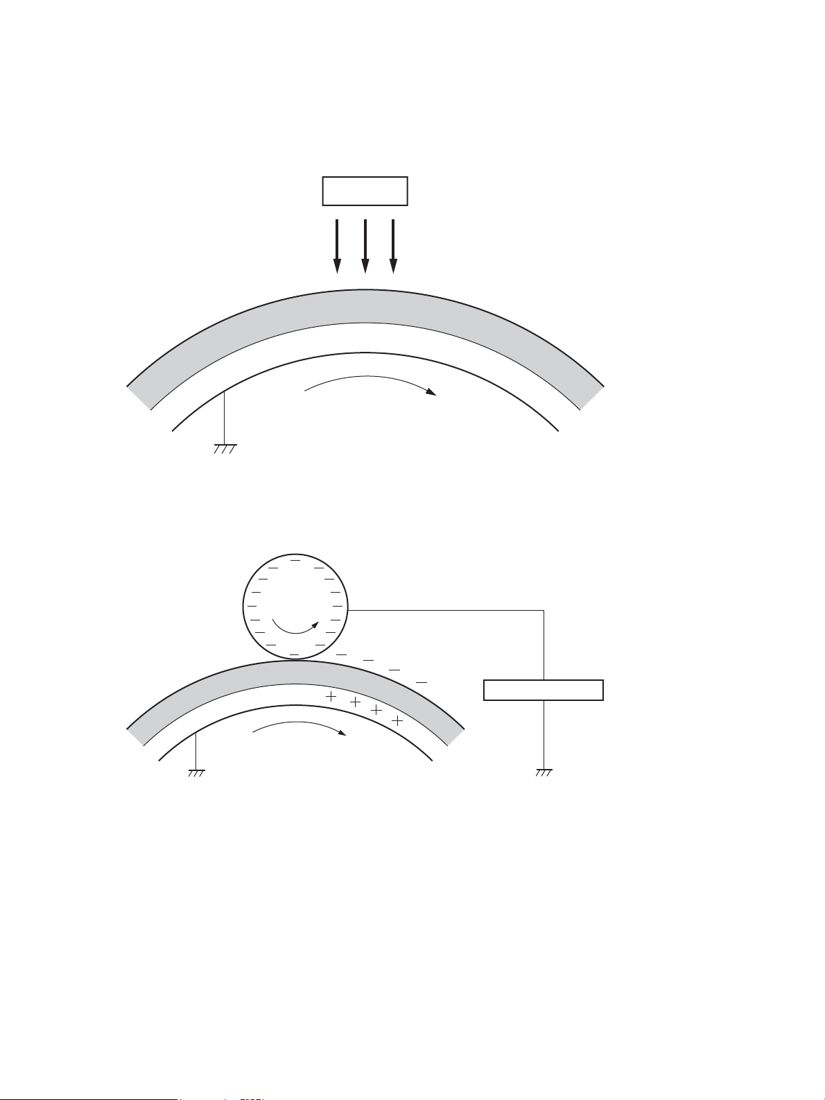
Step 1: Pre-exposure
LED
Photosensitive drum
Primary charging bias
Primary charging roller
Photosensitive drum
Light from the pre-exposure LED strikes the surface of the photosensitive drum to remove any residual electrical
charges from the drum surface.
Figure 1-13 Pre-exposure
Step 2: Primary charging
The primary-charging roller contacts the photosensitive drum and charges the drum with negative potential.
Figure 1-14 Primary charging
34 Chapter 1 Theory of operation ENWW
Page 59

Step 3: Laser-beam exposure
Photosensitive drum
Laser beam
Developer blade
Developer roller
Developing bias
Photosensitive drum
The laser beam strikes the surface of the photosensitive drum in the areas where the image will form. The
negative charge neutralizes in those areas, which are then ready to accept toner.
Figure 1-15 Laser-beam exposure
Step 4: Development
Toner acquires a negative charge as the developing cylinder contacts the developing blade. Because the
negatively-charged surface of the photosensitive drums have been neutralized where they have been struck by
the laser beam, the toner adheres to those areas on the drums. The latent image becomes visible on the surface
of each drum.
Figure 1-16 Development
ENWW Engine laser scanner system 35
Page 60

Step 5: Primary transfer
T1 roller
T1 bias
ITB
Photosensitive
drum
ITB
Paper
T2 roller
T2 bias
The positively-charged primary-transfer rollers contact the ITB, giving the ITB a positive charge. The ITB attracts
the negatively-charged toner from the surface of each photosensitive drum, and the complete toner image
transfers onto the ITB.
Figure 1-17 Primary transfer
Step 6: Secondary transfer
The paper acquires a positive charge from the secondary-transfer roller, and attracts the negatively-charged
toner from the surface of the ITB. The complete toner image transfers onto the paper.
Figure 1-18 Secondary transfer
36 Chapter 1 Theory of operation ENWW
Page 61

Step 7: Separation
ITB
Paper
T2 roller
Static charge eliminator
Paper
Fuser heater
Fuser film
Pressure roller
Fusing bias
The stiness of the paper causes it to separate from the ITB as the ITB bends. The static-charge eliminator
removes excess charge from the paper to make sure that the toner fuses correctly.
Figure 1-19 Separation
Step 8: Fusing
To create the permanent image, the paper passes through heated, pressurized rollers to melt the toner onto the
page. Fusing bias is added to the pressure roller to improve the print quality.
Figure 1-20 Fusing
ENWW Engine laser scanner system 37
Page 62
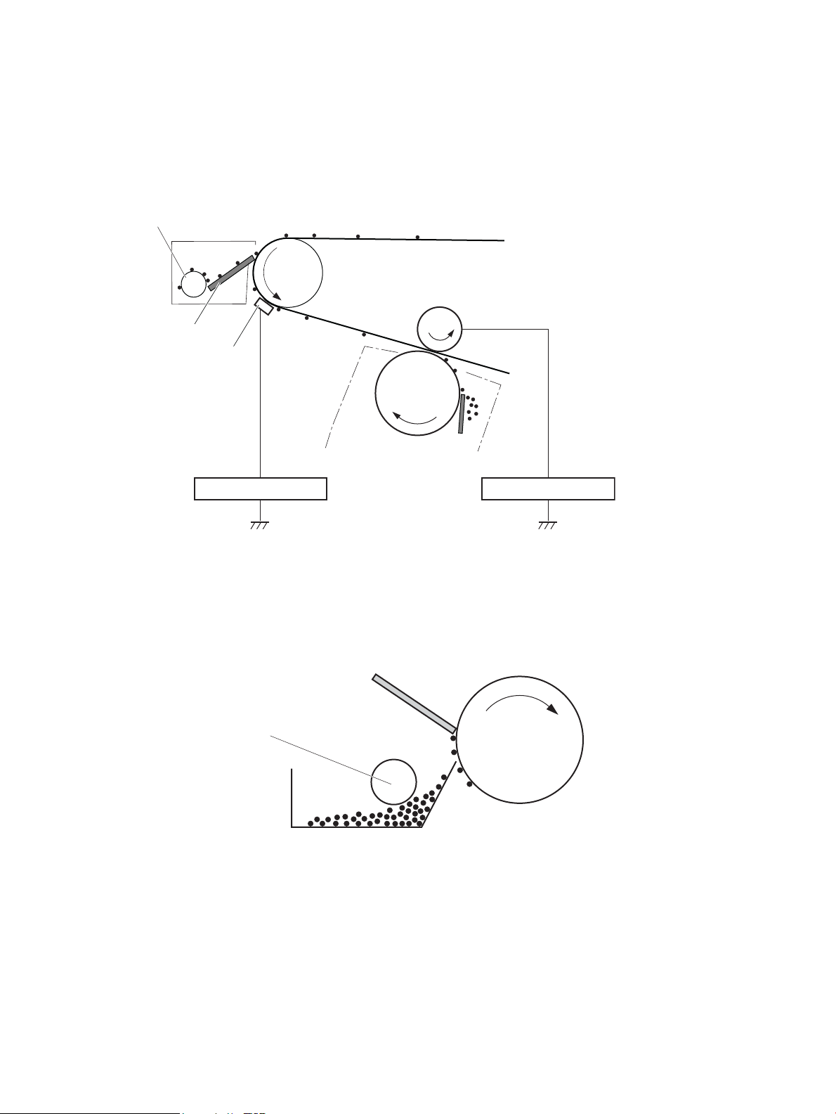
Step 9: ITB cleaning
Toner feed screw
Cleaning blade
ITB cleaning brush
ITB brush bias
Photosensitive
drum
T1 roller
ITB
T1 bias
Photosensitive
drum
Cleaning blade
Toner feed screw
The cleaning blade scrapes the residual toner o the surface of the ITB. The residual toner feed screw deposits
residual toner in the toner collection unit. The residual toner which cannot be removed by the cleaning blade is
charged by the ITB cleaning brush, and then transferred from the ITB surface to the photosensitive drum by the
primary transfer (T1) roller.
Figure 1-21 ITB Cleaning
Step 10: Drum cleaning
The cleaning blade scrapes the residual toner o the surface of the photosensitive drum. The toner feed screw
deposits the residual toner in the toner collection unit.
Figure 1-22 Drum cleaning
38 Chapter 1 Theory of operation ENWW
Page 63
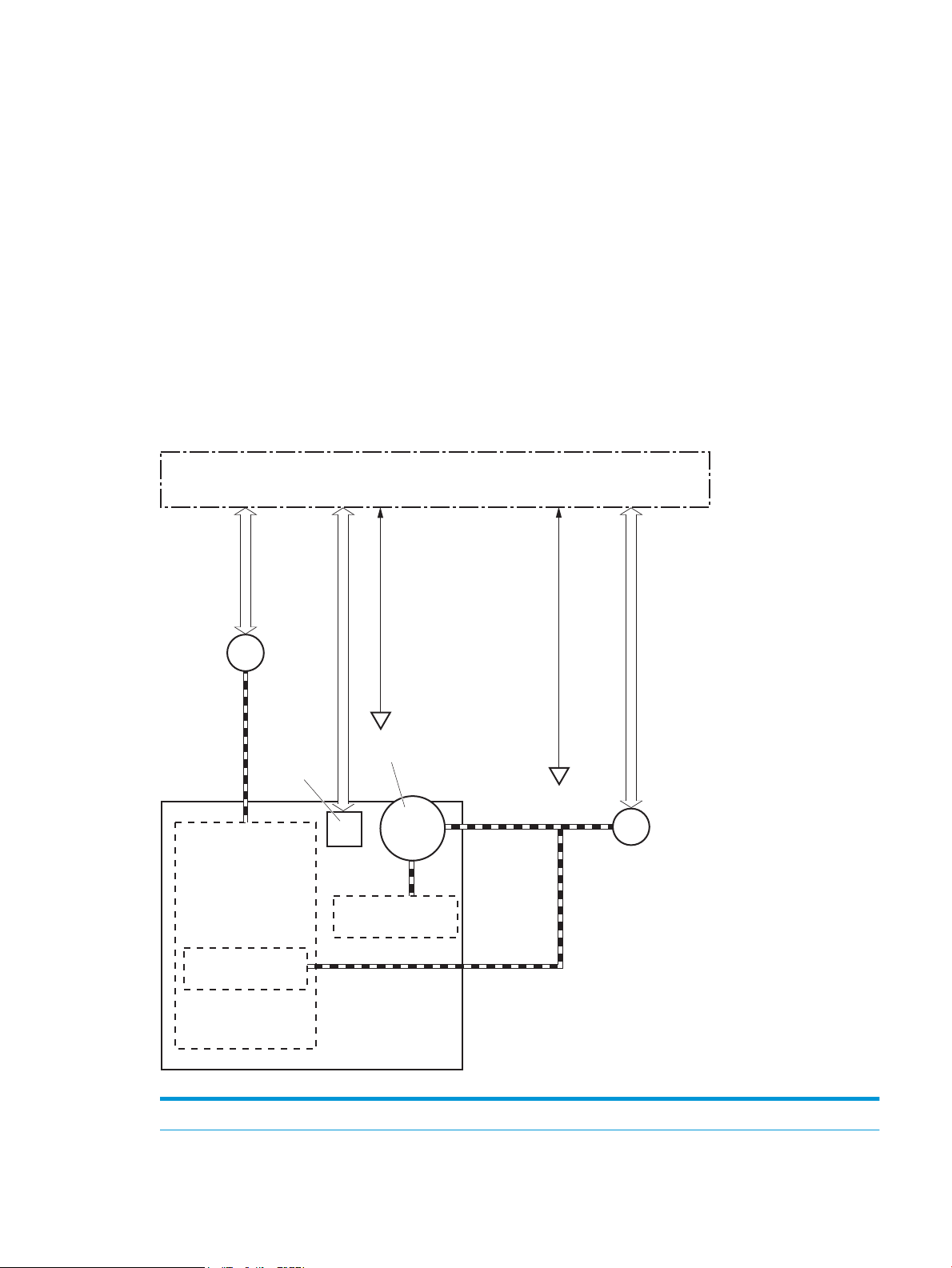
Toner cartridges
SR54
Developer
DC controller
M6
E-label
Developer roller
Cartridge
Primary charging
roller
Photosensitive drum
M
M1/M2/M3
SR51/SR52/SR53
The printer has four toner cartridges, one for each color: cyan, magenta, yellow, and black.
Design
Each toner cartridge is lled with toner and consists of the following components:
● Photosensitive drum
● Developer roller
● Primary-charging roller
● Memory chip
The DC controller rotates the drum motor to drive the photosensitive drum, developer roller, and the primarycharging roller.
Figure 1-23 Toner cartridge system
Table 1-15 Toner cartridge functions
Function Applied
ENWW Engine laser scanner system 39
Page 64

Table 1-15 Toner cartridge functions (continued)
Cartridge presence detection Yes
Toner level detection Yes
Cartridge life detection Yes
Cartridge mis-installation detection Yes
Developer alienation control Yes
Developer alienation motor failure detection Yes
Drum discharge mechanism No
40 Chapter 1 Theory of operation ENWW
Page 65

Memory chip
The memory chip is non-volatile memory that stores information about the usage of the toner cartridge and
helps protect the customer from counterfeit cartridges. This chip is also used to detect the presence of a
cartridge within the printer or when a cartridge is installed in the wrong slot. The printer reads and writes the
data in the memory chip.
Dynamic security
Certain HP printers use cartridges that have security chips or electronic circuitry. Cartridges using a non-HP chip
or modied or non-HP circuitry* might not work. And, those that work today might not work in the future.
As is standard in the printing business, HP has a process for authenticating cartridges. HP continues to use
security measures to protect the quality of our customer experience, maintain the integrity of our printing
systems, and protect our intellectual property. These measures include authentication methods that change
periodically and might prevent some third-party supplies from working now or in the future. HP printers and
original HP cartridges deliver the best quality, security and reliability. When cartridges are cloned or
counterfeited, the customer is exposed to quality and potential security risks, compromising the printing
experience.
* Non-HP chips and modied or non-HP electronic circuitry are not produced or validated by HP. HP cannot
guarantee that these chips or circuitry will work in your printer now or in the future. If you are using a nonoriginal HP cartridge, please check with your supplier to ensure your cartridge has an original HP security chip or
unmodied HP electronic circuitry.
JetIntelligence
JetIntelligence supports two features for managing toner cartridges.
● The authentication feature allows customers to specify the use of only genuine HP toner cartridges in the
● The anti-theft feature enables locking a cartridge to a specic printer or eet of printers.
Authentication
The genuine HP authentication feature allows a customer to specify that only genuine HP supplies can be used in
a printer. If a non-HP or used supply is installed, the printer will not print. This feature is disabled by default, and
can be enabled or disabled from the control panel or the Embedded Web Server (EWS).
If a genuine HP toner cartridge from another printer is moved to a printer with this feature enabled, the toner
cartridge will authenticate and print, unless the toner cartridge has passed the low state. If the toner cartridge
has passed the low state, an Unauthorized Cartridge message displays on the control panel.
If a non-HP toner cartridge is used in a printer with this feature enabled, the message Unauthorized Cartridge
appears on the control-panel display.
NOTE: If a customer suspects they have a counterfeit cartridge, they should report it by going to
www.hp.com/go/anticounterfeit and selecting Report now.
Anti-theft
printer.
The toner cartridge anti-theft feature allows a customer to congure the printer to automatically lock genuine
HP toner cartridges to a specic printer or eet of printers when they are installed. A locked toner cartridge will
only work in the specied printer or eet of printers. This feature prevents toner cartridges from being stolen
and used in another printer, or from being moved from an authorized printer to an unauthorized printer. This
ENWW Engine laser scanner system 41
Page 66

feature is disabled by default, and can be enabled or disabled from the control panel, the Embedded Web Server
(EWS), or Web Jetadmin.
When the anti-theft feature is enabled, the toner cartridge in a printer will only work in the specied printer or
eet of printers. If a locked toner cartridge is moved to another printer, the cartridge will not print and the
message Protected Cartridge appears on the control-panel display.
NOTE: When a toner cartridge is locked to a specic printer or eet of printers, it cannot be unlocked. This is a
permanent operation.
Toner seal
The toner cartridge seal is opened automatically when the toner cartridge is installed into the printer.
Toner level and cartridge life detection
Toner level detection: The DC controller detects the remaining toner in the cartridge by the optical detection
method and then noties the formatter of the remaining toner level.
Cartridge life detection: Cartridge life detection is measured in two ways.
1. Toner level:
– For the rst 75% of cartridge life, toner level is measure through pixel counting by the DC controller.
Once the level reaches 25%, the toner level sensor utilizes electrical properties to determine the
amount of toner remaining.
2. Rotations of internal components (OPC and developer roller):
– The DC controller monitors these two life parameters and reports them to the formatter as percent
life remaining. End of cartridge life is determined by the lower value of the two.
Developing unit engagement and disengagement control
The printer can print in full-color mode or in black-only mode. To print in black-only mode, the printer disengages
the developing rollers in the cyan, magenta, and yellow toner cartridges, which maximizes the life of the
cartridges.
42 Chapter 1 Theory of operation ENWW
Page 67

Figure 1-24 Developer roller engagement and alienation control
Developing unit is disengaged
Developing
disengagement
motor
Photosensitive drum
Developing unit
Developing disengagement cam
SR4
Developing home position sensor
DC controller
M6
Developing unit is engaged
The developer roller engagement and alienation control operates as follows: When the printer is turned on and
when each print job is completed, all four of the developing units are disengaged from the photosensitive drums.
● The drive of the developer alienation motor rotates the developer alienation cam.
● As the cam rotates, the developing unit engages with or separates from the photosensitive drum.
When the print mode is full color, the developing units engage with the drums. When the print mode is blackonly, only the black developing unit engages with the drum.
The DC controller determines a developer alienation motor failure and noties the formatter when it does not
detect a specied signal from the developer alienation sensor during the developing unit engagement and
disengagement operation.
ENWW Engine laser scanner system 43
Page 68

Intermediate transfer belt (ITB) unit
DC controller
ITB toner collection
near full switch
ITB cleaner
Toner collection box
SR1901
T1 roller
ITB drive roller
Drum motor 3
M3
ITB
M4 Fuser motor
T1 roller alienation
solenoid
SL1
The ITB unit accepts the toner images from the photosensitive drums and transfers the completed image to the
paper. The ITB unit has the following main components:
● Intermediate transfer belt (ITB)
● ITB-drive roller
● Primary-transfer roller
●
ITB cleaner
Drum motor 3 drives the ITB drive roller, which rotates the ITB. The motion of the ITB causes the primary transfer
rollers to rotate. The ITB cleaner cleans the ITB surface.
Figure 1-25 ITB Unit
Table 1-16 ITB assembly functions
Function Applied
T1 roller alienation control Yes
T1 roller alienation mechanism failure detection Yes
ITB ass’y life detection Yes
ITB ass’y presence detection No
Blade cleaning mechanism Yes
Electrostatic cleaning mechanism Yes
ITB toner collection box full detection Yes
ITB toner collection box presence detection No
ITB perimeter detection Yes
ITB seal detection sensor failure detection No
44 Chapter 1 Theory of operation ENWW
Page 69

Primary-transfer roller engagement and disengagement control
Depending on the requirements of the print job, the primary-transfer rollers engage with the ITB so it can receive
toner from the photosensitive drums. The primary-transfer rollers have three engagement states.
Table 1-17 Primary-transfer roller engagement states
All rollers disengaged The ITB is disengaged from all the four photosensitive drums. This state is the home
position for the ITB unit.
All rollers engaged The ITB is engaged with all four photosensitive drums. This is the state for full-color
printing.
Black roller engaged The ITB is engaged with only the black photosensitive drum. This is the state for black-only
printing.
ENWW Engine laser scanner system 45
Page 70

Figure 1-26 Three states of primary-transfer roller engagement and disengagement
Four colors are disengaged
Four colors are engaged
Only black is engaged
Y
M
C
K
Y
M
C
K
Y
M
C
K
Y
M
C
K
Y
M
C
K
Y
M
C
K
Fuser motor
Fuser motor control
M4
SR5
Primary transfer roller
disengagement signal
Primary transfer roller
disengagement solenoid
control signal
The primary-transfer-roller disengagement motor rotates or reverses to place the primary-transfer-roller
disengagement cam into one of three positions. The cam causes the transfer-roller slide plate to move to the
right or left. This movement causes the primary-transfer rollers to move up to engage the ITB with the
photosensitive drum or down to disengage it.
The DC controller expects to receive a signal from the ITB home-position sensor when the primary-transfer
roller engages or disengages. If the DC controller does not receive this signal, but detects that the primarytransfer-roller disengagement motor is rotating, the DC controller determines that the primary-transferdisengagement mechanism has failed, and noties the formatter. The formatter will then display a 59.00.F0
message on the control panel.
46 Chapter 1 Theory of operation ENWW
Page 71

ITB unit detection
The DC controller monitors several signals from the ITB unit to detect status.
ITB unit life detection The DC controller detects whether the ITB unit is new by monitoring the new ITB
ITB unit presence detection The DC controller detects the presence of an ITB unit by monitoring the primary-
unit sensor. The DC controller determines the ITB unit is at end of life and noties
the formatter when a specied number of pages are printed after the ITB unit is
replaced. If swapping ITB units between two printers for troubleshooting purposes,
be sure to return the ITB units to their original printers to maintain the correct life
count.
NOTE: When installing a new ITB, refer to the instructions for resetting the ITB life
counter in the installation guide provided with the replacement part.
transfer roller disengagement sensor. The DC controller turns on the primarytransfer disengagement solenoid for specied times during an initial rotation period
when the following events occur:
● The printer is turned on
● The printer exits sleep mode
● The door is closed
The DC controller determines the absences of an ITB unit and noties the formatter
when it does not detect a specied signal from the new primary-transfer roller
disengagement sensor.
ENWW Engine laser scanner system 47
Page 72

ITB cleaning mechanism
The cleaning blade in the ITB cleaner scrapes the residual toner o the ITB surface and deposits the residual
toner into the toner collection unit. The residual toner feed screw deposits the residual toner to the residual
toner feed unit. The ITB motor and the residual toner feed motor drive the screw. The residual toner that cannot
be removed by the cleaning blade is charged by the ITB cleaning brush, and then transferred from the ITB
surface to the photosensitive drum by the primary transfer (T1) roller. The DC controller detects whether the
toner collection unit is full by using the toner collection unit full sensor, and then noties the formatter.
Figure 1-27 ITB cleaning process
Secondary transfer roller functions
The secondary transfer roller transfers the image from the ITB onto the paper.
The printer has the following secondary transfer roller functions.
Table
1-18 Secondary transfer roller functions
Function Supported feature
Secondary transfer roller cleaning mechanism Yes
Secondary transfer roller presence detection No
Secondary transfer roller life detection No
Secondary transfer roller alienation control Yes
48 Chapter 1 Theory of operation ENWW
Page 73

Calibration
The printer calibrates itself to maintain proper print quality. The calibration corrects color-misregistration and
color-density variation due to environmental changes or internal variation in the printer.
The printer has the following calibration functions.
Table 1-19 Calibration functions
Function Supported feature
Color-plane registration correction control Yes
Environment correction control Yes
Image density control (DMAX) Yes
Image halftone control (DHALF) Yes
Registration density sensor failure detection Yes
Color sensor control No
Gray axis control (GAS) No
Environment sensor failure detection Yes
ENWW Engine laser scanner system 49
Page 74

Pickup, feed, and delivery system
The DC controller controls the pickup, feed, and delivery system according to commands from the formatter. The
pickup, feed, and delivery system uses a series of rollers to move the paper through the printer.
The pickup, feed, and delivery system consists of the following three functional blocks. The DC controller
controls each block to pick up, feed and deliver the paper.
● Pickup-and-feed-block: Controls the movement of the paper from each pickup source to the fuser inlet
● Fuser-and-delivery-block: Controls the movement of the paper from the fuser to the delivery destination
● Duplex block: Controls the movement of the paper from the duplex switchback unit to the duplex re-pickup
unit.
50 Chapter 1 Theory of operation ENWW
Page 75

Simplex paper path
Duplex block
Pickup-and-feed block
Fuser-and-delivery block
Duplex paper path
Simplex paper path
Figure 1-28 Pickup, feed, and delivery system
Photo sensors and switches
The following gure shows the sensors and switches for the pickup, feed, and delivery system.
ENWW Pickup, feed, and delivery system 51
Page 76

Figure 1-29 Pickup, feed, and delivery system photo sensors and switches
SW5
SR14
SR95
SR94
SR12/13
MS
SR11
SR8615
SR8611/8613
SR62
Table 1-20 Photo sensors and switches
Abbreviation Component name
SR11 Registration sensor
SR12 Registration media width sensor 1
SR13 Registration media width sensor 2
SR14 Tray 2 media out sensor
SR62 FD1 media full sensor
SR94 Duplex feed sensor
SR95 Tray 1 media out sensor
SR8611 Fuser output sensor 1
SR8613 Fuser output sensor 2
SR8615 Fuser loop sensor
SW5 Tray 2 media size switch 1
MS Media sensor
52 Chapter 1 Theory of operation ENWW
Page 77

Motors, clutches, and solenoids
M8
M4
SL3
M5
CL1 CL2 SL2
M3
M8
The following gure shows the motors, clutches, and solenoids for the pickup, feed, and delivery system.
Figure 1-30 Pickup, feed, and delivery system motors, clutches, and solenoids
Table 1-21 Motors, clutches, and solenoids
Abbreviation Component Replacement part number
M3 Drum motor 3 Drum motor assembly (RM2-1956-000CN)
M4 Fuser motor Fuser motor assembly (RM2-1955-000CN)
M5 Pickup motor Paper pickup assembly (RM2-6556-000CN)
M8 Duplex reverse motor Right door assembly (RM2-6622-000CN)
SL2 Tray 1 pickup solenoid Right door assembly (RM2-6622-000CN)
SL3 Duplex reverse solenoid Right door assembly (RM2-6622-000CN)
CL1 Tray 2 pickup clutch Lifter drive assembly (RM2-6669-000CN)
CL2 Duplex re-pickup clutch Right door assembly (RM2-6622-000CN)
ENWW Pickup, feed, and delivery system 53
Page 78

Paper trays
Tray 2 media type detection
The printer selects the optimal print mode based upon the media type detected by the media sensor. The media
sensor consists of an optical sensor, which detects the surface texture of the paper, and an ultrasonic sensor,
which measures the thickness of the paper. The formatter informs the DC controller that the printer is in autosense mode and the DC controller changes the fuser mode based on media type.
Following are the print modes detected by the printer:
● Normal
● Heavy media 1
● Heavy media 2
● Heavy media 3
● Light media 1
● Light media 2
● Light media 3
● Glossy media 1
● Glossy media 2
● Glossy media 3
● Glossy
● OHT
● Designated media 1
● Designated media 2
● Designated media 3
The DC controller determines a media sensor error and reports it to the formatter when the value detected by
the media sensor is out of a specied range of values.
54 Chapter 1 Theory of operation ENWW
Page 79

Figure 1-31 Media sensors
Ultrasonic sensor
Registration ass’y
Optical sensor
Feed speed control
The DC controller adjusts the feed speed to improve the print quality depending on the paper type. The paper is
fed at a specied speed according to the print mode designated by the formatter.
Table 1-22 Print mode and feed speed
Print mode
Feed speed
1
Media sensor detection
Full color Monochrome
Auto - - Yes
Normal 1/1 1/1 Yes
Heavy media 1 3/4 3/4 No
Heavy media 2 1/2 1/2 Yes
Heavy media 3 1/3 1/3 Yes
Light media 1 1/1 1/1 Yes
Light media 2 1/1 1/1 Yes
Light media 3 1/2 1/2 Yes
Glossy media 1 1/3 1/3 Yes
Glossy media 2 1/3 1/3 Yes
Glossy media 3 1/3 1/3 Yes
Glossy lm 1/3 1/3 Yes
Photo media 1 - - No
Photo media 2 - - No
Photo media 3 - - No
Envelope 1 1/3 1/3 No
Envelope 2 - - No
Envelope 3 - - No
ENWW Pickup, feed, and delivery system 55
Page 80

Table 1-22 Print mode and feed speed (continued)
Print mode
OHT 1/3 1/3 Yes
Label 1/2 1/2 No
Designated media 1 1/2 1/2 No
Designated media 2 1/3 1/3 No
Designated media 3 3/4 3/4 No
1/1 speed = 210 mm/s
1/2 speed = 105 mm/s
1/3 speed = 70 mm/s
Feed speed
Full color Monochrome
1
Media sensor detection
Table 1-23 Pickup, feed and delivery system functions
Function Supported
Tray 2 media size detection Yes
Tray 2 presence detection Yes
Tray 2 media surface detection No
Tray 2 media presence detection Yes
Tray 2 media level detection No
Tray 2 lift-up control Yes
Tray 2 lift-down control No
Tray 2 multiple-feed prevention mechanism Yes
Tray 1 media presence detection Yes
Tray 1 media width detection No
Tray 1 last-media detection No
Skew-feed prevention mechanism Yes
Feed speed control Yes
Loop control Yes
Media detection Yes
OHT detection Yes
Image leading edge positioning Yes
Media length detection Yes
Media width detection Yes
Pressure roller pressure release control Yes
Output bin media-full detection Yes
Automatic delivery Yes
56 Chapter 1 Theory of operation ENWW
Page 81

Table 1-23 Pickup, feed and delivery system functions (continued)
Function Supported
Duplex switchback control Yes
Duplex feed control Yes
Duplexing unit
The duplexing unit reverses the paper and feeds it through the paper path to print the second side.
Duplexing reverse and duplex feed control
The duplex reverse control reverses the paper after the rst side is printed and feeds it to the duplex re-pickup
position to print the second side of the page.
1. At a specied time after the rst side of a page is printed, the duplex reverse motor rotates, and the duplex
reverse solenoid is turned on.
2. The duplex apper moves, and the paper feeds to the duplex reverse unit.
3. After a specied period of time, the duplex reverse motor reverses, and the paper feeds to the duplex feed
unit.
4. The duplex reverse motor and the pickup motor move the paper to the duplex re-pickup position.
5. The duplex reverse motor and the duplex feed clutch stop, and the paper feed operation pauses.
6. After a specied period of time, the duplex reverse motor rotates, and the duplex feed clutch is turned on.
The paper is then picked up again.
Jam detection/prevention
The printer uses the following sensors to detect the paper as it moves through the paper path and to report to
the DC controller if the paper has jammed.
● Registration sensor (SR11)
● Registration media width sensor 1 (SR12)
● Registration media width sensor 2 (SR13)
● FD1 (output bin) media full sensor (SR62)
● Duplex feed sensor (SR94)
● Fuser output sensor 1 (SR8611)
● Fuser output sensor 2 (SR8613)
● Fuser loop sensor (SR8615)
● PF (paper feeder) feed sensor (PS3602) — 550-sheet paper feeder only
● PD (paper deck) cassette 1 feed sensor (PS3401) — 1x550-sheet paper-feeder, 3x550-sheet paper-
feeder, and 2,550-sheet paper-feeder only
ENWW Pickup, feed, and delivery system 57
Page 82

● PD (paper deck) cassette 2 feed sensor (PS4501) — 3x550-sheet paper-feeder and 2,550-sheet paper-
SR11
SR62
SR94
SR12/13
SR8615
SR8611/8613
SR3602
feeder only
● PD (paper deck) cassette 3 feed sensor (PS5601) — 3x550-sheet paper-feeder only
Figure 1-32 Paper-path jam detection sensors
The printer determines that a jam has occurred if one of these sensors detects paper at an inappropriate time.
The DC controller stops the print operation and noties the formatter.
58 Chapter 1 Theory of operation ENWW
Page 83
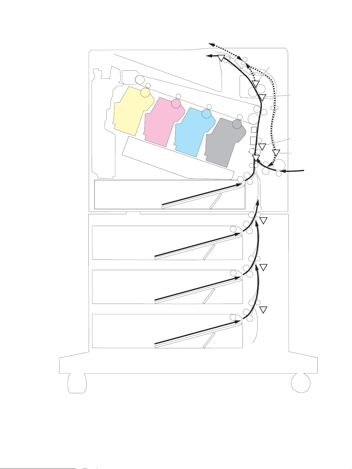
Figure 1-33 paper-feeder paper-path jam detection sensors
SR3602
SR11
SR94
SR12/13
SR8615
SR62
SR8611/8613
SR4501
SR5601
ENWW Pickup, feed, and delivery system 59
Page 84

Table 1-24 Jams that the printer detects
Jam Supported feature
No pick jam 1 Yes
No pick jam 2 Yes
No pick jam 3 Yes
No pick jam 4 No
Pickup stay jam 1 Yes
Pickup stay jam 2 No
Pickup stay jam 3 No
Pickup stay jam 4 No
Fuser delivery delay jam 1 Yes
Fuser delivery delay jam 2 No
Fuser delivery delay jam 3 No
Fuser delivery delay jam 4 No
Fuser delivery stay jam 1 Yes
Fuser delivery stay jam 2 No
Fuser delivery stay jam 3 No
Fuser delivery stay jam 4 No
Residual paper jam 1 Yes
Residual paper jam 2 No
Residual paper jam 3 No
Residual paper jam 4 No
Door open jam 1 Yes
Door open jam 2 No
Door open jam 3 No
Door open jam 4 No
Fuser wrap jam1 Yes
Fuser wrap jam2 No
Fuser wrap jam3 No
Fuser wrap jam4 No
Duplex switchback jam1 No
Duplex switchback jam2 No
Duplex switchback jam3 No
Duplex switchback jam4 No
Duplex re-pickup jam 1 Yes
60 Chapter 1 Theory of operation ENWW
Page 85

Table 1-24 Jams that the printer detects (continued)
Jam Supported feature
Duplex re-pickup jam 2 No
Duplex re-pickup jam 3 No
Duplex re-pickup jam 4 No
Delivery delay jam 1 Yes
Delivery delay jam 2 No
Delivery delay jam 3 No
Delivery delay jam 4 No
Delivery stay jam 1 No
Delivery stay jam 2 No
Delivery stay jam 3 No
Delivery stay jam 4 No
Multiple feed jam 1 No
Multiple feed jam 2 No
Multiple feed jam 3 No
Multiple feed jam 4 No
Duplex feed delay jam 1 Yes
Inappropriate to the delivery path Jam 1 No
Inappropriate to the delivery path Jam 2 No
Fuser wrapping jam detection
The printer includes controls for detecting when a jam occurs causing the paper to wrap around the fuser roller.
Loop control
The loop control stabilizes the paper feed operation before the paper enters the fuser. If the pressure roller
rotates slower than the secondary transfer roller, the paper loop increases and an image defect or paper crease
occurs. If the pressure roller rotates faster than the secondary transfer roller, the paper loop decreases and a
vertical scanning magnication failure occurs because the pressure roller pulls the paper.
To prevent these problems, the loop sensor detects the paper loop before the paper enters the fuser. The DC
controller adjusts the rotational speed of the fuser motor according to the output signals from the loop sensor
and maintains the paper loop. The DC controller slows the fuser motor when the sensor is o and speeds up the
motor when the sensor is on.
Pressure roller pressurization and depressurization control
To prevent excessive wear on the pressure roller and help with jam-clearing procedures, the pressure roller
pressurizes only during printing and standby. The DC controller reverses the fuser motor. The fuser motor
rotates the fuser pressure-release cam.
The pressure roller depressurizes under the following conditions:
ENWW Pickup, feed, and delivery system 61
Page 86

● The printer is turned o
● Any failure occurs
● During power-save mode
A paper jam is detected
●
If the DC controller does not sense the fuser pressure-release sensor for a specied period after it reverses the
fuser motor, it noties the formatter that a fuser pressure-release mechanism failure has occurred.
62 Chapter 1 Theory of operation ENWW
Page 87

Input accessories
NOTE: Optional 1x550-sheet, 3x550 sheet, and 2,550 paper feeders are available for this printer. The printer
supports up to three of these paper feeders at a time.
550-sheet paper feeder
The 550-sheet paper feeder is installed under the printer. It picks up paper and feeds it into the printer.
Figure 1-34 550-sheet paper feeder
550-sheet paper feeder controller
The paper feeder controller controls the operational sequence of the paper feeder.
ENWW Input accessories 63
Page 88

Figure 1-35 550-sheet paper feeder driver PCA
Clutch
Switch
Photointerruptor
DC controller Paper feeder controller
+3.3VB
+24VA
Motor
550-sheet paper feeder
550-sheet paper feeder motor control
The 550-sheet paper feeder has one motor for lifting the tray and feeding paper.
Table
1-25 550-sheet paper feeder motor control
Component Drives Failure detection
M3602 Feed motor (550-sheet paper feeder) Tray pickup roller (B5L24-67904)
550-sheet paper feeder electrical components
The paper feeder contains several motors, solenoids, sensors, and switches, as described in the following table.
Table
1-26 550-sheet paper feeder electrical components
Component type Abbreviation Component name Replacement part number
Motor M3602 Feed motor (550-sheet paper feeder) Paper feed assembly
Clutch CL3602 Tray pick up clutch (550-sheet paper
feeder)
Switches SW3601 Right door switch (550-sheet paper
SW3602 Tray detection switch (550-sheet paper
Sensors PS3601 Tray media-out sensor (550-sheet
feeder)
feeder)
paper feeder)
Tray feed roller (RM2-6684-000CN)
Paper feed assembly (RM2-5145-000CN)
Lifter drive assembly (RM2-6669-000CN)
(RM2-5145-000CN)
Lifter drive assembly
(RM2-5149-000CN)
Right door (RM2-5146-000CN)
Switch button (WC2-5806-000CN)
Paper pick up assembly
(RM2-5154-000CN)
No
64 Chapter 1 Theory of operation ENWW
Page 89

Table 1-26 550-sheet paper feeder electrical components (continued)
M3602
PS3601
PS3602
SW3602
CL3602
SW3601
Component type Abbreviation Component name Replacement part number
PS3602 Feed sensor (550-sheet paper feeder) Paper feed assembly
550-sheet paper feeder paper pickup
The 550-sheet paper feeder picks up one sheet from the paper-feeder tray and feeds it to the printer.
Figure 1-36 Paper pickup and feed operation (550-sheet paper feeder)
(RM2-5145-000CN)
Table 1-27 Pickup feed components (1x550-sheet paper feeder)
Abbreviation Component Replacement part number
M3602 Feed motor (550-sheet paper feeder) Paper feed assembly (RM2-5145-000CN)
CL3602 Tray pickup clutch (550-sheet paper feeder) Part not available
SW3601 Media size switch
SW3602 Door switch
PS3601 Tray media-out sensor (550-sheet paper feeder) Paper pick up assembly (RM2-5154-000CN)
PS3602 Feed sensor (550-sheet paper feeder) Paper feed assembly (RM2-5145-000CN)
550-sheet paper feeder multiple feed prevention
The multiple-feed prevention for the 550-sheet paper feeder is operated in the same way as that of the printer
base.
550-sheet paper feeder tray presence detection
The presence detection for the 550-sheet paper feeder is the same way as that of the printer base.
ENWW Input accessories 65
Page 90

550-sheet paper feeder tray lift operation
The 550-sheet paper feeder keeps the paper stack surface at the correct pickup position. The tray lift operation
occurs under the following conditions:
● The printer is turned on.
● The tray is inserted.
● The paper stack surface of the tray lowers.
The sequence occurs as follows:
1. The feeder tray-lifting motor rotates and the lifter moves up.
2. When the paper-feeder media-stack-surface sensor detects the stack surface of the paper, the lifting
motor stops.
3. The lifting motor rotates again to lift the lifter when the paper-feeder media-stack-surface sensor detects
the stack surface, and then lowers during printing.
If a tray media-stack-surface sensor does not detect a stack surface within a specied period after the lifting
motor starts rotating, the paper feeder driver determines that the lifting motor has failed and noties the
formatter through the DC controller.
The paper-feeder driver noties the formatter if either of the paper-feeder media-stack-surface sensors fails to
detect the stack surface within a specied period from when a lift-up operation starts.
66 Chapter 1 Theory of operation ENWW
Page 91

550-sheet paper feeder jam detection
The 550-sheet paper feeder uses the feed sensor (SR21) and right door switch (SW20) to detect the presence of
paper and to check whether paper has jammed.
The 550-sheet paper feeder detects the following jams:
● Media input delay jam 1 (550-sheet paper feeder): Paper did not reach the registration sensor in time.
● Media input delay jam 2 (550-sheet paper feeder): Paper did not reach the source tray feed sensor in time.
● Media input delay jam 3 (550-sheet paper feeder): Paper did not reach the tray 3 feed sensor in time.
● Pickup stationary jam (550-sheet paper feeder): The feed sensor does not detect the trailing edge of paper
within a specied time after the sensor detects the leading edge.
● Residual paper jam (550-sheet paper feeder): The feed sensor detects the presence of paper for a
specied time during an automatic delivery operation.
● Right door open jam (550-sheet paper feeder): The right door open is detected during a paper feed
operation.
ENWW Input accessories 67
Page 92

550-sheet paper-feeder
Figure 1-37 Paper path (1x550-sheet paper-feeder)
68 Chapter 1 Theory of operation ENWW
Page 93
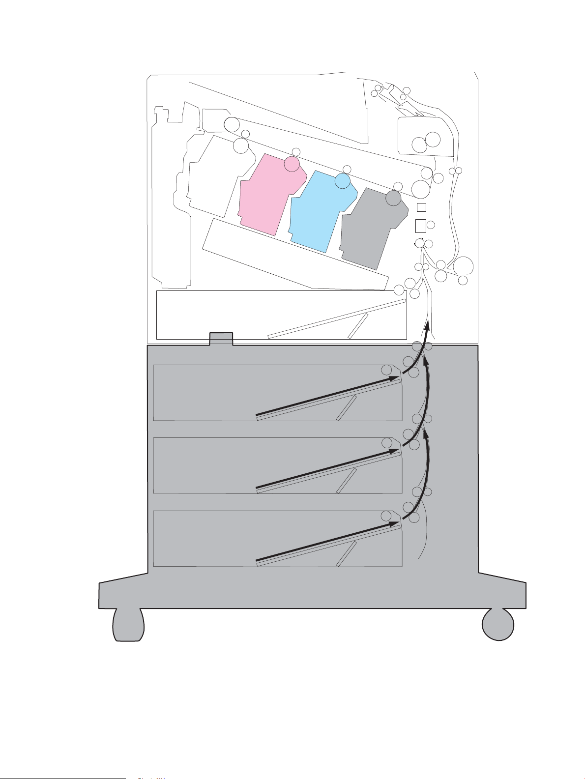
Figure 1-38 Paper path (3x550-sheet paper-feeder)
ENWW Input accessories 69
Page 94

Figure 1-39 Paper path (2,550-sheet paper-feeder)
70 Chapter 1 Theory of operation ENWW
Page 95

Figure 1-40 paper-feeder controller
Clutch
Switch
Photointerruptor
DC controller Paper deck controller
+3.3VB
+24VA
Motor
1x550-sheet paper deck/3x550-sheet paper deck/2550-sheet paper deck
Table 1-28 Paper-feeder electrical component list
Component type Abbreviation Component name 1x550 PD 3x550 PD2,550 PD
Motor M3401 PD cassette 1 lifter motor Yes Yes Yes
M3402 PD feed motor 1 Yes Yes Yes
M4501 PD cassette 2 lifter motor No Yes Yes
M4502 PD feed motor 2 No Yes Yes
M5601 PD cassette 3 lifter motor No Yes No
M5602 PD feed motor 3 No Yes No
Clutch CL3401 PD cassette 1 pickup clutch Yes Yes Yes
CL4501 PD cassette 2 pickup clutch No Yes Yes
CL5601 PD cassette 3 pickup clutch No Yes No
Switch SW3401 PD Cassette 1 media size switch 1 Yes Yes Yes
SW3402 PD Cassette 1 media size switch 2 Yes Yes Yes
SW4501 PD Cassette 2 media size switch 1 No Yes Yes
SW4502 PD Cassette 2 media size switch 2 No Yes No
SW5601 PD Cassette 3 media size switch 1 No Yes No
SW5602 PD Cassette 3 media size switch 2 No Yes No
SW3403 PD door switch Yes Yes Yes
Photointerrupter PS3401 PD cassette 1 feed sensor Yes Yes Yes
PS3402 PD cassette 1 media out sensor Yes Yes Yes
PS3403 PD cassette 1 media surface sensor Yes Yes Yes
PS3413 PD pickup roller alienation sensor Yes Yes Yes
ENWW Input accessories 71
Page 96

Table 1-28 Paper-feeder electrical component list (continued)
Component type Abbreviation Component name 1x550 PD 3x550 PD2,550 PD
Motor control
Component name Components driven
M3401 PD Cassette 1 lifter motor Lift up the cassette 1
M3402 PD feed motor 1 Cassette pickup roller, cassette feed roller, and feed roller
M4501 PD Cassette 2 lifter motor
PS4501 PD cassette 2 feed sensor No Yes Yes
PS4502 PD cassette 2 media out sensor No Yes Yes
PS4503 PD cassette 2 media surface sensor No Yes Yes
PS5601 PD cassette 3 feed sensor No Yes No
PS5602 PD cassette 3 media out sensor No Yes No
PS5603 PD cassette 3 media surface sensor No Yes No
Lift up the cassette 2 or tray
1
M4502 PD feed motor 2 Cassette pickup roller, cassette feed roller, tray pickup roller, tray feed roller, and
M5601 PD Cassette 3 lifter motor
M5602 PD feed motor 3
1
Only for 3x550-sheet paper-feeder and 2,550-sheet paper-feeder
2
Only for 3x550-sheet paper-feeder
Pickup-and-feed Operation
The paper-feeder picks up the sheet of paper one by one in the paper-feeder cassette and feeds it to the printer.
feed roller
Lift up the cassette 3
1
2
Cassette pickup roller, cassette feed roller and feed roller
2
72 Chapter 1 Theory of operation ENWW
Page 97

Figure 1-41 1x550-sheet paper-feeder/3x550-sheet paper-feeder electrical components
M4502
M3401
PS5603
PS5602
PS5601
CL5601
M5602
M3402
SW5601
SW5602
M5601
SW4501
SW4502
M4501
PS3402
SW3403
PS3401
PS4501
PS4502
PS3413
PS4503
PS3403
SW3401
SW3402
CL3401
CL4501
Table 1-29 Electrical component list (1x550-sheet paper-feeder/3x550-sheet paper-feeder)
Abbreviation Component name 1x550 PD 3x550 PD
M3401 PD cassette 1 lifter motor Yes Yes
M3402 PD feed motor 1 Yes Yes
M4501 PD cassette 2 lifter motor No Yes
M4502 PD feed motor 2 No Yes
M5601 PD cassette 3 lifter motor No Yes
M5602 PD feed motor 3 No Yes
CL3401 PD cassette 1 pickup clutch Yes Yes
CL4501 PD cassette 2 pickup clutch No Yes
CL5601 PD cassette 3 pickup clutch No Yes
SW3401 PD Cassette 1 media size switch 1 Yes Yes
SW3402 PD Cassette 1 media size switch 2 Yes Yes
SW4501 PD Cassette 2 media size switch 1 No Yes
SW4502 PD Cassette 2 media size switch 2 No Yes
SW5601 PD Cassette 3 media size switch 1 No Yes
SW5602 PD Cassette 3 media size switch 2 No Yes
SW3403 PD door switch Yes Yes
PS3401 PD cassette 1 feed sensor Yes Yes
PS3402 PD cassette 1 media out sensor Yes Yes
ENWW Input accessories 73
Page 98
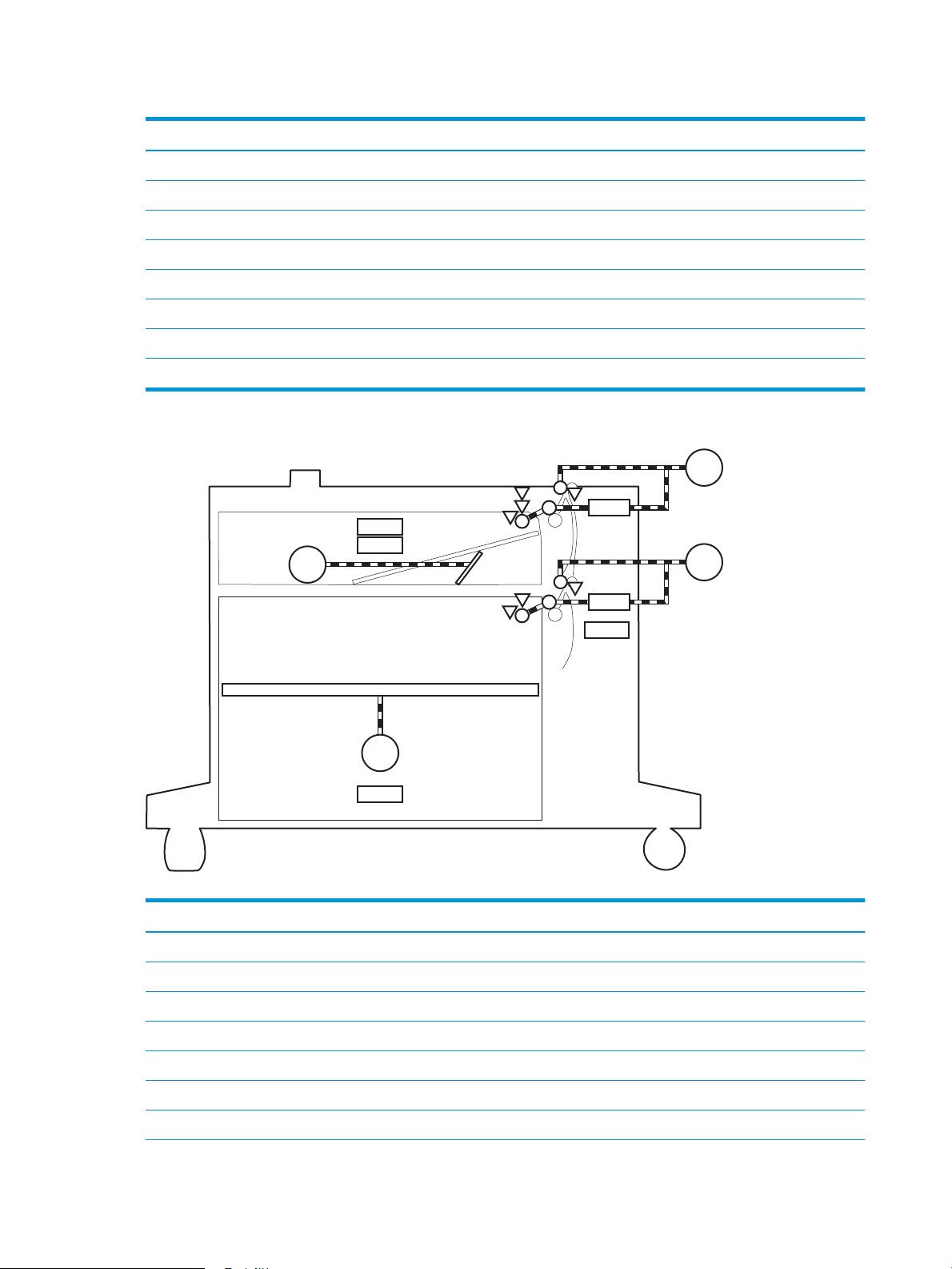
Table 1-29 Electrical component list (1x550-sheet paper-feeder/3x550-sheet paper-feeder) (continued)
M3402
M4501
PS3402
SW3403
PS3401
PS4501
PS4502
PS3413
PS4503
PS3403
SW4501
SW3401
SW3402
CL3401
CL4501
M3401
M4502
Abbreviation Component name 1x550 PD 3x550 PD
PS3403 PD cassette 1 media surface sensor Yes Yes
PS3413 PD pickup roller alienation sensor Yes Yes
PS4501 PD cassette 2 feed sensor No Yes
PS4502 PD cassette 2 media out sensor No Yes
PS4503 PD cassette 2 media surface sensor No Yes
PS5601 PD cassette 3 feed sensor No Yes
PS5602 PD cassette 3 media out sensor No Yes
PS5603 PD cassette 3 media surface sensor No Yes
Figure 1-42 Outline of electrical component (2,550-sheet paper-feeder)
Table 1-30 Electrical component list (2,550-sheet paper-feeder)
Abbreviation Component name
M3401 PD cassette 1 lifter motor
M3402 PD feed motor 1
M4501 PD cassette 2 lifter motor
M4502 PD feed motor 2
CL3401 PD cassette 1 pickup clutch
CL4501 PD cassette 2 pickup clutch
SW3401 PD Cassette 1 media size switch 1
74 Chapter 1 Theory of operation ENWW
Page 99

Table 1-30 Electrical component list (2,550-sheet paper-feeder) (continued)
Abbreviation Component name
SW3402 PD Cassette 1 media size switch 2
SW4501 PD Cassette 2 media size switch 1
SW3403 PD door switch
PS3401 PD cassette 1 feed sensor
PS3402 PD cassette 1 media out sensor
PS3403 PD cassette 1 media surface sensor
PS3413 PD pickup roller alienation sensor
PS4501 PD cassette 2 feed sensor
PS4502 PD cassette 2 media out sensor
PS4503 PD cassette 2 media surface sensor
Table 1-31 Paper-feeder functions
Function Supported
Cassette lift-up control Yes
Cassette presence detection Yes
Cassette media size detection Yes
Cassette media stack surface detection Yes
Cassette media out detection Yes
Cassette media level detection No
Multiple-feed prevention Yes
Automatic delivery Yes
ENWW Input accessories 75
Page 100

Staple stacker multi bin mailbox
The staple stacker multi bin mailbox (SSMBM) is installed on the upper side of the printer, and it delivers the print
media to output tray after the staple process. The SSMBM controller controls the operation sequence of the
SSMBM.
Figure 1-43 Staple stacker multi bin mailbox paper path
76 Chapter 1 Theory of operation ENWW
 Loading...