

Page 1

LaserJet Enterprise M607, M608, M609
LaserJet Enterprise MFP M631, M632, M633
www.hp.com/support/ljM607
www.hp.com/support/ljM608
www.hp.com/support/ljM609
www.hp.com/support/ljM631MFP
www.hp.com/support/ljM632MFP
www.hp.com/support/ljM633MFP
Troubleshooting Manual
For printer part removal procedures and parts
diagrams information, see the Repair Manual.
M607n, M607dn,
M608n, M608dn, M608dh, M609dn
M608x, M609x
M631dn
Flow M631h
M632h
M633fh
Flow M632z
Flow M633z
M631z M632fht
Page 2

Page 3

HP LaserJet Enterprise M607, M608, M609.
MFP M631, MFP M632, MFP M633
Troubleshooting Manual
Page 4

Copyright and License
Trademark Credits
© Copyright 2017 HP Development Company,
L.P.
Reproduction, adaptation, or translation
without prior written permission is prohibited,
except as allowed under the copyright laws.
The information contained herein is subject to
change without notice.
The only warranties for HP products and
services are set forth in the express warranty
statements accompanying such products and
services. Nothing herein should be construed
as constituting an additional warranty. HP shall
not be liable for technical or editorial errors or
omissions contained herein.
Edition 1, 5/2017
Microsoft®, Windows®, Windows® XP, and
Windows Vista® are U.S. registered trademarks
of Microsoft Corporation.
Page 5

Conventions used in this guide
TIP: Helpful hints or shortcuts.
Reinstallation tip: Reinstallation helpful hints, shortcuts, or considerations.
NOTE: Information that explains a concept or how to complete a task.
IMPORTANT: Information that help the user to avoid potential printer error conditions.
CAUTION: Procedures that the user must follow to avoid losing data or damaging the printer.
WARNING! Procedures that the user must follow to avoid personal injury, catastrophic loss of data, or
extensive damage to the printer.
ENWW iii
Page 6

iv Conventions used in this guide ENWW
Page 7

For additional service and support information
HP service personnel, go to the Service Access Work Bench (SAW) at http://sawpro.glb.itcs.hp.com.
Channel partners, go to HP Channel Services Network (CSN) at www.hp.com/partners/csn .
At these locations, nd information on the following topics:
●
Install and congure
●
Printer specications
●
Up-to-date control panel message (CPMD) troubleshooting
●
Solutions for printer issues and emerging issues
●
Remove and replace part instructions and videos
●
Service advisories
●
Warranty and regulatory information
Channel partners, access training materials in the HP University and Partner Learning Center at
https://content.ext.hp.com/sites/LMS/HPU.page.
To access HP PartSurfer information from any mobile device, go to http://partsurfermobile.hp.com/ or scan
the Quick Response (QR) code below.
ENWW v
Page 8

vi For additional service and support information ENWW
Page 9

Table of contents
1 Theory of operation ....................................................................................................................................... 1
Related documentation and software ................................................................................................................... 2
Basic operation ...................................................................................................................................................... 3
Sequence of operation ........................................................................................................................ 4
Engine-control system .......................................................................................................................................... 5
DC controller ........................................................................................................................................ 6
Motors ............................................................................................................................... 7
Fans ................................................................................................................................... 8
Solenoids ........................................................................................................................... 8
Clutches ............................................................................................................................. 8
Switches ............................................................................................................................ 8
Photointerrupter sensors ............................................................................................... 10
Sensors ........................................................................................................................... 10
LEDs ................................................................................................................................. 10
Low-voltage power supply ................................................................................................................ 11
Low-voltage power supply voltages description ........................................................... 12
Over-current/over-voltage protection ........................................................................... 12
Safety .............................................................................................................................. 12
Low-voltage power supply functions ............................................................................. 13
High-voltage power supply ............................................................................................................... 13
High-voltage power supply circuits ................................................................................ 13
Fuser control ..................................................................................................................................... 14
Fuser circuits ................................................................................................................... 15
Fuser control functions ................................................................................................... 16
Fuser heater protection .................................................................................................. 18
Laser scanner system .......................................................................................................................................... 19
Laser/scanner failure detection ........................................................................................................ 20
Safety ................................................................................................................................................ 20
Image formation system ..................................................................................................................................... 21
Image-formation process ................................................................................................................. 24
Step 1: Pre-exposure ...................................................................................................... 24
Step 2: Primary charging ................................................................................................ 25
ENWW vii
Page 10

Step 3: Laser-beam exposure ......................................................................................... 26
Step 4: Development ...................................................................................................... 26
Step 5: Transfer ............................................................................................................... 27
Step 6: Separation ........................................................................................................... 27
Step 7: Fusing .................................................................................................................. 28
Step 8: Drum cleaning ..................................................................................................... 28
Toner cartridge .................................................................................................................................................... 29
Design ................................................................................................................................................ 29
Pickup, feed, and delivery system ....................................................................................................................... 30
Photo sensors and switches ............................................................................................................. 33
Motors, clutches, and solenoids ........................................................................................................ 34
Jam detection/prevention ................................................................................................................. 35
Input accessories ................................................................................................................................................. 38
550-sheet paper feeder (PF) ............................................................................................................. 38
Controller ........................................................................................................................ 38
Paper path ....................................................................................................................... 38
Pickup and feed components ......................................................................................... 39
Jam detection .................................................................................................................. 42
2,100-sheet paper deck (HCI) ........................................................................................................... 42
Controller ........................................................................................................................ 42
Paper path ....................................................................................................................... 42
Pickup and feed components ......................................................................................... 43
Jam detection .................................................................................................................. 46
1x550, 3x550, 2,550-sheet paper decks (PD) .................................................................................. 46
Controller ........................................................................................................................ 46
Paper path ....................................................................................................................... 46
Pickup and feed components ......................................................................................... 49
Paper deck jam detection ............................................................................................... 53
Output accessories .............................................................................................................................................. 54
2-bin staple stacker multi-bin mailbox (SSMBM) ............................................................................. 54
Controller ........................................................................................................................ 54
Paper path ....................................................................................................................... 54
Motors ............................................................................................................................. 55
Fan ................................................................................................................................... 56
Delivery functions ........................................................................................................... 56
Delivery operation .......................................................................................................... 56
Jam detection .................................................................................................................. 59
5-bin staple stacker multi bin mailbox (SSMBM) .............................................................................. 60
Controller ........................................................................................................................ 61
Paper path ....................................................................................................................... 61
Motors ............................................................................................................................. 63
viii ENWW
Page 11

Fan ................................................................................................................................... 63
Delivery functions ........................................................................................................... 63
Delivery operation .......................................................................................................... 64
Jam detection .................................................................................................................. 66
Scanning and image capture system (M631, M632, M633) ................................................................................ 69
Document feeder system (M631, M632, M633) ................................................................................................. 70
Document feed system ..................................................................................................................... 70
Sensors in the document feeder ....................................................................................................... 70
Document feeder paper path ............................................................................................................ 71
Document feeder simplex operation ................................................................................................ 72
Document feeder e-duplex operation .............................................................................................. 73
Deskew operation .............................................................................................................................. 74
Document feeder hinges ................................................................................................................... 74
2 Solve problems ............................................................................................................................................ 77
Solve problems checklist ..................................................................................................................................... 79
Solve problems checklist ................................................................................................................... 79
Print menu map ................................................................................................................................. 84
Print current settings pages ............................................................................................................. 84
View, print and clear the event log ................................................................................................... 85
View or print the event log from the Troubleshooting menu ........................................ 85
View, print, or clear the event log from the Service menu ............................................. 86
Pre-boot menu options ..................................................................................................................... 87
Remote Admin ................................................................................................................. 97
Required software and network connection ................................................ 97
Connect a remote connection ....................................................................... 99
Disconnect a remote connection ................................................................ 103
Troubleshooting process ................................................................................................................................... 106
Determine the problem source ....................................................................................................... 106
Pre-troubleshooting checklist ...................................................................................... 106
Troubleshooting owchart ........................................................................................... 107
Power subsystem ............................................................................................................................ 108
Power-on checks ........................................................................................................... 108
Power-on troubleshooting overview ......................................................... 109
Control panel checks (touchscreen models) ................................................................................... 114
Control-panel diagnostics (touchscreen models) ........................................................ 114
Touchscreen diagnostic mode (touchscreen models) ............................... 114
Control-panel system diagnostics (touchscreen models) ......................... 119
Control panel diagnostic owcharts (touchscreen models) ........................................ 134
Touchscreen black, white, or dim (no image) ............................................ 135
Touchscreen has an unresponsive zone .................................................... 136
ENWW ix
Page 12

No control panel sound .............................................................................. 137
Home button is unresponsive .................................................................... 138
Hardware integration pocket (HIP) is not functioning (control panel
functional) .................................................................................................. 139
Tools for troubleshooting .................................................................................................................................. 140
Individual component diagnostics .................................................................................................. 141
Tools for troubleshooting: LED diagnostics ................................................................. 141
Understand lights on the formatter ........................................................... 141
Tools for troubleshooting: Engine diagnostics ............................................................ 144
Engine test button ...................................................................................... 144
Defeating interlocks ................................................................................... 145
Disable cartridge check .............................................................................. 147
Tools for troubleshooting: Paper path and sensor diagnostic tests ........................... 147
Paper path page ......................................................................................... 147
Paper path sensors test ............................................................................. 148
Manual sensor tests ................................................................................... 151
Tools for troubleshooting: Print/stop test ................................................................... 153
Tools for troubleshooting: Component tests ............................................................... 155
Individual component diagnostics ............................................................. 155
Tools for troubleshooting: Scanner tests (MFP) ........................................................... 157
Continuous scan test (MFP) ........................................................................ 157
Tools for troubleshooting: Scanner tests (MFP) ........................................................... 158
Run fax test (MFP) ...................................................................................... 158
Diagrams ......................................................................................................................................... 159
Diagrams: Block diagrams ............................................................................................ 159
Diagrams Electrical components ............................................................... 159
Diagrams: External plug and port locations .............................................. 171
Diagrams: Locations of major assemblies ................................................. 173
Diagrams: General timing chart ................................................................................... 193
Diagrams: General circuit diagrams ............................................................................. 194
Internal test and information pages ............................................................................................... 202
Print a conguration page ............................................................................................ 202
Wireless page ............................................................................................. 204
HP embedded Jetdirect page ..................................................................... 206
Fax accessory page ..................................................................................... 207
Finding important information on the conguration pages ..................... 208
Print a fuser test page .................................................................................................. 210
Control-panel menus ...................................................................................................................... 211
Copy menu (MFP models only) ..................................................................................... 213
Scan menu (MFP models only) ..................................................................................... 216
Print menu .................................................................................................................... 217
x ENWW
Page 13

HP JetAdvantage menu (MFP models only) ................................................................. 218
Quick Sets menu (MFP models only) ............................................................................ 219
Contacts menu (fax models only) ................................................................................. 220
Supplies menu .............................................................................................................. 221
Trays menu ................................................................................................................... 223
Reports menu ............................................................................................................... 226
Settings menu ............................................................................................................... 228
Support Tools menu ..................................................................................................... 233
Control panel message document (CPMD) ..................................................................................... 240
Control-panel messages and event log entries ........................................................... 240
Improve print quality ......................................................................................................................................... 241
Improve print quality ...................................................................................................................... 241
Introduction .................................................................................................................. 241
Print from a dierent software program ..................................................................... 241
Check the paper-type setting for the print job ............................................................ 241
Check the paper type setting (Windows) ................................................... 241
Check the paper type setting (OS X) .......................................................... 242
Check toner-cartridge status ....................................................................................... 242
Print a cleaning page .................................................................................................... 242
Visually inspect the toner cartridge ............................................................................. 243
Check paper and the printing environment .................................................................. 243
Step one: Use paper that meets HP specications .................................... 243
Step two: Check the environment .............................................................. 243
Step three: Set the individual tray alignment ............................................ 244
Try a dierent print driver ............................................................................................ 244
Check the EconoMode settings .................................................................................... 245
Adjust print density ...................................................................................................... 245
Print quality troubleshooting guide .................................................................................................................. 247
Introduction ..................................................................................................................................... 248
Toner cartridges ............................................................................................................ 249
Check toner-cartridge status ..................................................................... 249
Visually inspect the toner cartridge or cartridges ..................................... 249
Check the paper-type setting for the print job ............................................................ 250
Check paper and the printing environment .................................................................. 250
Information to collect ................................................................................................... 251
Product specic image defects ....................................................................................................... 251
Resolving print quality problems ................................................................................. 251
Introduction ................................................................................................ 251
Troubleshoot print quality problems ......................................................... 252
Repetitive image defect ruler ....................................................................................... 259
Use a ruler to measure between repetitive defects .................................. 260
ENWW xi
Page 14

Printer specic image defects ...................................................................................... 263
Image defect events ................................................................................... 263
Clean the printer ................................................................................................................................................ 279
Clean the paper path ....................................................................................................................... 279
Print a cleaning page ....................................................................................................................... 279
Check the scanner glass for dirt and smudges (MFP) ..................................................................... 280
Clean the pickup rollers and separation pad in the document feeder (MFP) ................................. 282
Clean the Tray 1 roller and separation pad ..................................................................................... 284
Step 1: Clean the Tray 1 roller ....................................................................................... 284
Step 2: Clean the separation pad assembly ................................................................. 285
Clean the Tray 2-X rollers ................................................................................................................ 287
Step 1: Clean the Tray 2-X rollers ................................................................................. 287
Solve paper handling problems ........................................................................................................................ 294
Printer feeds incorrect page size .................................................................................................... 294
Printer pulls from incorrect tray ..................................................................................................... 294
Printer will not duplex or duplexes incorrectly ............................................................................... 294
Paper does not feed from Tray 2-X ................................................................................................. 295
Output is curled or wrinkled ............................................................................................................ 295
Printer does not pick up paper or misfeeds .................................................................................... 296
The printer does not pick up paper .............................................................................. 296
The printer picks up multiple sheets of paper ............................................................. 297
The document feeder jams, skews, or picks up multiple sheets of paper (MFP) ........ 297
Paper does not feed automatically .............................................................................. 297
Clear paper jams .............................................................................................................................. 299
Paper path jam sensor locations .................................................................................. 300
Paper jam locations (M631, M632, and M633) ............................................................ 307
Paper jam locations (M607, M608, and M609) ............................................................ 308
Auto-navigation for clearing jams ................................................................................ 308
Experiencing frequent or recurring paper jams? ......................................................... 308
Clear paper jams in the document feeder .................................................................... 310
Clear paper jams in Tray 1(M631, M632, and M633) .................................................... 312
Clear paper jams in Tray 1 (M607, M608, and M609) ................................................... 312
Clear paper jams in Trays 2, 3, 4, or 5 (M631, 632, and 633) ...................................... 317
Clear paper jams in Trays 2, 3, or 4 (M607, M608, and M609) ..................................... 317
Clear paper jams in the 2,550-sheet high-capacity input tray (M631, M632, and
M633) ............................................................................................................................ 325
Clear paper jams in the 2,100-sheet high-capacity input tray (M607, M608, and
M609) ............................................................................................................................ 325
Clear paper jams in the right door and fuser area (M631, M632, and M633) .............. 331
Clear paper jams in the rear door and fuser area (M607, M608, and M609) ............... 334
Clear paper jams in the output bin (M631, M632, and M633) ...................................... 337
xii ENWW
Page 15

Clear paper jams in the output bin (M607, M608, and M609) ...................................... 337
Clear paper jams in the duplexer (M631, M632, and M631) ........................................ 339
Clear paper jams in the duplexer (M607, M608, and M609) ........................................ 341
Clear paper jams in the envelope feeder (M631, M632, and M633) ............................ 343
Clear paper jams in the envelope feeder (M607, M608, and M609) ............................ 343
Clear paper jams in the HP Stapling Mailbox (M631, M632, and M633) ...................... 347
Clear paper jams in the HP Stapling Mailbox accessory (M607, M608, and M609) ..... 347
Clear staple jams (M631, M632, and M633) ................................................................. 350
Clear staple jams (M607, M608, and M609) ................................................................. 350
Change jam recovery .................................................................................................... 356
Solve performance problems ............................................................................................................................ 357
Factors aecting print performance ............................................................................................... 357
Print speeds ..................................................................................................................................... 358
The printer does not print or it prints slowly .................................................................................. 359
The printer prints slowly ................................................................................................................. 359
Solve connectivity problems ............................................................................................................................. 361
Solve wired network problems ....................................................................................................... 361
Introduction .................................................................................................................. 361
Poor physical connection .............................................................................................. 361
The computer is unable to communicate with the printer ........................................... 361
The printer is using incorrect link and duplex settings for the network ..................... 362
New software programs might be causing compatibility problems ........................... 362
The computer or workstation might be set up incorrectly .......................................... 362
The printer is disabled, or other network settings are incorrect ................................. 362
Solve wireless network problems ................................................................................................... 362
Introduction .................................................................................................................. 363
Wireless connectivity checklist ..................................................................................... 363
The printer does not print after the wireless conguration completes ...................... 364
The printer does not print, and the computer has a third-party rewall installed ..... 364
The wireless connection does not work after moving the wireless router or printer . 364
Cannot connect more computers to the wireless printer ............................................ 364
The wireless printer loses communication when connected to a VPN ........................ 365
The network does not appear in the wireless networks list ........................................ 365
The wireless network is not functioning ...................................................................... 365
Reduce interference on a wireless network ................................................................. 365
Service mode functions ..................................................................................................................................... 366
Service menu ................................................................................................................................... 366
Printer resets ................................................................................................................................... 371
Restore factory-set defaults ........................................................................................ 371
Printer cold reset .......................................................................................................... 371
Format Disk and Partial Clean functions ........................................................................................ 373
ENWW xiii
Page 16

Active and repository rmware locations .................................................................... 373
Partial Clean .................................................................................................................. 373
Execute a Partial Clean ............................................................................... 374
Format Disk ................................................................................................................... 374
Execute a Format Disk ................................................................................ 375
Firmware upgrades ............................................................................................................................................ 377
Determine the installed revision of rmware ................................................................................. 378
Perform a rmware upgrade .......................................................................................................... 380
HP Embedded Web Server ............................................................................................ 380
USB ash drive (control-panel menu) .......................................................................... 381
USB ash drive (Pre-boot menu) .................................................................................. 383
Solve fax problems (M631, M632, M633) ......................................................................................................... 385
Solve email problems (M631, M632, M633) ..................................................................................................... 385
Appendix A Printer specications .................................................................................................................. 387
Printer dimensions ............................................................................................................................................ 388
Printer dimensions (M607, M608, M609) ....................................................................................... 388
Printer dimensions (M631, M632, M633) ....................................................................................... 391
Printer space requirements ............................................................................................................................... 394
Power consumption, electrical specications, and acoustic emissions ........................................................... 394
Operating environment range ........................................................................................................................... 394
Certicate of Volatility ....................................................................................................................................... 395
Index ........................................................................................................................................................... 399
xiv ENWW
Page 17

List of tables
Table 1-1 Sequence of operation .......................................................................................................................................... 4
Table 1-2 Motors ................................................................................................................................................................... 7
Table 1-3 Fans ....................................................................................................................................................................... 8
Table 1-4 Solenoids ............................................................................................................................................................... 8
Table 1-5 Clutches ................................................................................................................................................................. 8
Table 1-6 Switches ................................................................................................................................................................ 8
Table 1-7 Photointerrupter sensors ................................................................................................................................... 10
Table 1-8 Sensors ............................................................................................................................................................... 10
Table 1-9 LEDs .................................................................................................................................................................... 10
Table 1-10 Converted DC voltages ..................................................................................................................................... 12
Table 1-11 Low-voltage power supply functions ............................................................................................................... 13
Table 1-12 High-voltage power supply circuits ................................................................................................................. 14
Table 1-13 Fuser components ............................................................................................................................................ 15
Table 1-14 Fuser-control functions .................................................................................................................................... 18
Table 1-15 Motors ............................................................................................................................................................... 22
Table 1-16 Sensors ............................................................................................................................................................. 23
Table 1-17 Image formation process ................................................................................................................................. 24
Table 1-18 Toner cartridge functions ................................................................................................................................. 29
Table 1-19 Pickup, feed, and delivery functions ................................................................................................................ 32
Table 1-20 Photo sensors and switches ............................................................................................................................. 33
Table 1-21 Motors, solenoids, and clutches ....................................................................................................................... 34
Table 1-22 Paper path sensors ........................................................................................................................................... 37
Table 1-23 Jams that the printer detects ........................................................................................................................... 37
Table 1-24 Pickup and feed components for the 550-sheet PF ........................................................................................ 40
Table 1-25 Pickup and feed functions for the 550-sheet PF ............................................................................................. 40
Table 1-26 Pickup and feed components for the 2,100-sheet HCI .................................................................................... 44
Table 1-27 Paper pickup and feed functions for the 2,100-sheet HCI .............................................................................. 45
Table 1-28 Pickup and feed components for 1x550 paper deck and 3x550 paper deck .................................................. 50
Table 1-29 Pickup and feed components for the 2,550-sheet paper deck ....................................................................... 52
Table 1-30 Pickup and feed functions for the 1x550, 3x550, and 2,550 paper decks ..................................................... 53
Table 1-31 Motors for the 2-bin SSMBM ............................................................................................................................ 56
Table 1-32 Fan for the 2-bin SSMBM .................................................................................................................................. 56
ENWW xv
Page 18

Table 1-33 Delivery functions for the SSMBM .................................................................................................................... 56
Table 1-34 Motors and solenoids for the 2-bin SSMBM ..................................................................................................... 57
Table 1-35 Sensors and switches for the 2-bin SSMBM ..................................................................................................... 58
Table 1-36 Motors for the 5-bin SSMBM ............................................................................................................................ 63
Table 1-37 Fan for SSMBM .................................................................................................................................................. 63
Table 1-38 Delivery functions for the SSMBM .................................................................................................................... 63
Table 1-39 Motors and solenoids for the 5-bin SSMBM ..................................................................................................... 64
Table 1-40 Sensors and switches for the 5-bin SSMBM ..................................................................................................... 66
Table 1-41 Document feeder sensors ................................................................................................................................ 71
Table 1-42 Document feeder paper path ........................................................................................................................... 71
Table 2-1 Pre-boot menu options (1 of 7) .......................................................................................................................... 90
Table 2-2 Pre-boot menu options (2 of 7) .......................................................................................................................... 91
Table 2-3 Pre-boot menu options (3 of 7) .......................................................................................................................... 92
Table 2-4 Pre-boot menu options (4 of 7) .......................................................................................................................... 93
Table 2-5 Pre-boot menu options (5 of 7) .......................................................................................................................... 93
Table 2-6 Pre-boot menu options (6 of 7) .......................................................................................................................... 94
Table 2-7 Pre-boot menu options (7 of 7) .......................................................................................................................... 95
Table 2-8 Troubleshooting owchart ............................................................................................................................... 107
Table 2-9 Heartbeat LED, printer operational .................................................................................................................. 142
Table 2-10 Printer base, sensors (image formation) block diagram ............................................................................... 160
Table 2-11 Printer base, sensors (pickup, feed, and delivery) block diagram ................................................................ 161
Table 2-12 Printer base, motors, solenoids, and clutches block diagram ...................................................................... 162
Table 2-13 1x550-sheet paper feeder, electrical components block diagram ............................................................... 163
Table 2-14 1x550-sheet and 3x550-sheet paper decks, electrical components block diagram ................................... 164
Table 2-15 2,550-sheet paper deck, electrical components block diagram ................................................................... 166
Table 2-16 Stapler stacker multi bin mailbox (5 bin; SSBM), motors and solenoids block diagram ............................... 167
Table 2-17 Stapler stacker multi bin mailbox (5 bin; SSBM), sensors and switches block diagram ............................... 168
Table 2-18 Stapler stacker multi bin mailbox (2 bin; SSBM), motors and solenoids block diagram ............................... 169
Table 2-19 Stapler stacker multi bin mailbox (2 bin; SSBM), sensors and switches block diagram ............................... 170
Table 2-20 External plug and port locations (M607, M608, and M609) .......................................................................... 171
Table 2-21 External plug and port locations (M631, M632, and M633) .......................................................................... 172
Table 2-22 Printer base (M607, M608, and M609), main assemblies (1 of 2) ................................................................. 173
Table 2-23 Printer base (M607, M608, and M609), main assemblies (2 of 2) ................................................................. 174
Table 2-24 Printer base (M631, M632, and M633), main assemblies (1 of 2) ................................................................. 175
Table 2-25 Printer base (M631, M632, and M633), main assemblies (2 of 2) ................................................................. 176
Table 2-26 Printer base, printed circuit assemblies (PCAs) ............................................................................................. 176
Table 2-27 Printer base (M607, M608, and M609), roller assemblies ............................................................................. 177
Table 2-28 rinter base (M631, M632, and M633), roller assemblies ............................................................................... 178
Table 2-29 1x550-sheet paper feeder, main assemblies ................................................................................................ 179
Table 2-30 1x550-sheet paper feeder (M631/M632/M633 envelope feeder), main assemblies .................................. 180
Table 2-31 1x550-sheet paper feeder, printed circuit assemblies (PCAs) ...................................................................... 181
xvi ENWW
Page 19

Table 2-32 1x550-sheet paper deck, main assemblies (1 of 2) ...................................................................................... 182
Table 2-33 1x550-sheet paper deck, main assemblies (2 of 2) ...................................................................................... 183
Table 2-34 1x550-sheet paper deck, printed circuit assemblies (PCAs) ......................................................................... 184
Table 2-35 3x550-sheet paper deck, main assemblies (1 of 2) ...................................................................................... 185
Table 2-36 3x550-sheet paper deck, main assemblies (2 of 2) ...................................................................................... 186
Table 2-37 3x550-sheet paper deck, printed circuit assemblies (PCAs) ......................................................................... 187
Table 2-38 2,100-sheet paper deck (M607/M608/M609), main assemblies .................................................................. 188
Table 2-39 2,100-sheet paper deck (M607/M608/M609), printed circuit assemblies (PCAs) ........................................ 189
Table 2-40 2,550-sheet paper deck (M631/M632/M633), main assemblies (1 of 2) ..................................................... 190
Table 2-41 2,550-sheet paper deck (M631/M632/M633), main assemblies (2 of 2) ..................................................... 191
Table 2-42 2,550-sheet paper deck (M631/M632/M633), printed circuit assemblies (PCAs) ........................................ 192
Table 2-43 Conguration page ......................................................................................................................................... 203
Table 2-44 Wireless page (1 of 2) ..................................................................................................................................... 204
Table 2-45 Wireless page (2 of 2) ..................................................................................................................................... 205
Table 2-46 HP embedded Jetdirect page ......................................................................................................................... 206
Table 2-47 Fax accessory page (1 of 2) ............................................................................................................................ 207
Table 2-48 Fax accessory page (2 of 2) ............................................................................................................................ 208
Table 2-49 Important information on the conguration pages ...................................................................................... 208
Table 2-50 Copy menu (MFP models only) ....................................................................................................................... 213
Table 2-51 Scan menu (MFP models only) ....................................................................................................................... 216
Table 2-52 Print menu ...................................................................................................................................................... 217
Table 2-53 HP JetAdvantage menu (MFP models only) ................................................................................................... 218
Table 2-54 Contacts menu (fax models only) .................................................................................................................. 220
Table 2-55 Supplies menu (fax models only) ................................................................................................................... 221
Table 2-56 Trays menu ..................................................................................................................................................... 223
Table 2-57 Reports menu (fax models only) .................................................................................................................... 226
Table 2-58 Settings menu (fax models only) ................................................................................................................... 228
Table 2-59 Support Tools menu ....................................................................................................................................... 233
Table 2-60 Image defects table quick reference .............................................................................................................. 252
Table 2-61 Light print ....................................................................................................................................................... 254
Table 2-62 Gray background or dark print ....................................................................................................................... 254
Table 2-63 Blank page — No print ................................................................................................................................... 255
Table 2-64 Black page ...................................................................................................................................................... 255
Table 2-65 Banding defects .............................................................................................................................................. 256
Table 2-66 Streak defects ................................................................................................................................................. 256
Table 2-67 Fixing/fuser defects ....................................................................................................................................... 257
Table 2-68 Image placement defects ............................................................................................................................... 257
Table 2-69 Color plane registrations defects (color models only) ................................................................................... 258
Table 2-70 Output defects ................................................................................................................................................ 258
Table 2-71 Repetitive defects .......................................................................................................................................... 259
Table 2-72 Printer feeds incorrect page size ................................................................................................................... 294
ENWW xvii
Page 20

Table 2-73 Printer pulls from incorrect tray .................................................................................................................... 294
Table 2-74 Printer will not duplex (print 2-sided jobs) or duplexes incorrectly .............................................................. 294
Table 2-75 Paper does not feed from Tray 2-X ................................................................................................................ 295
Table 2-76 Output is curled or wrinkled ........................................................................................................................... 295
Table 2-77 Paper does not feed automatically ................................................................................................................ 297
Table 2-78 Printer base, sensors (pickup, feed, and delivery) block diagram ................................................................ 300
Table 2-79 1x550-sheet paper feeder, electrical components block diagram ............................................................... 301
Table 2-80 1x550-sheet and 3x550-sheet paper decks, electrical components block diagram ................................... 302
Table 2-81 2,550-sheet paper deck, electrical components block diagram ................................................................... 304
Table 2-82 Stapler stacker multi bin mailbox (5 bin; SSBM), sensors and switches block diagram ............................... 305
Table 2-83 Stapler stacker multi bin mailbox (2 bin; SSBM), sensors and switches block diagram ............................... 306
Table 2-84 Solve performance problems ......................................................................................................................... 357
Table 2-85 Service menu .................................................................................................................................................. 367
Table A-1 Dimensions for M607n, M607dn, M608n, M608dn, M609dn models ............................................................. 388
Table A-2 Dimensions for M6608x, M609x ...................................................................................................................... 388
Table A-3 Dimensions for the 1x550-sheet paper feeder ............................................................................................... 388
Table A-4 Dimensions for the printer with a 1x550-sheet paper feeder ........................................................................ 388
Table A-5 Dimensions for the 2,100-sheet HCI with stand .............................................................................................. 389
Table A-6 Dimensions for the printer with a 2,100-sheet HCI with stand ....................................................................... 389
Table A-7 Dimensions for the envelope feeder ................................................................................................................ 389
Table A-8 Dimensions for the printer with an envelope feeder ....................................................................................... 389
Table A-9 Dimensions for the HP Stapling Mailbox .......................................................................................................... 389
Table A-10 Dimensions for the printer with an HP Stapling Mailbox .............................................................................. 390
Table A-11 Dimensions for base models (M631dn, M631h Flow, M632h, M633fh) ....................................................... 391
Table A-12 Dimensions for M631z ................................................................................................................................... 391
Table A-13 Dimensions for M632fht ................................................................................................................................ 391
Table A-14 Dimensions for M632z Flow, M633z Flow ..................................................................................................... 391
Table A-15 Dimensions for the 1x550-sheet paper feeder ............................................................................................. 391
Table A-16 Dimensions for the printer with a 1x550-sheet paper feeder ...................................................................... 392
Table A-17 Dimensions for the 1x550-sheet feeder with printer stand ......................................................................... 392
Table A-18 Dimensions for the printer with a 1x550-sheet feeder with printer stand .................................................. 392
Table A-19 Dimensions for the 1x550-sheet feeder and 2,100-sheet HCI with stand ................................................... 392
Table A-20 Dimensions for the printer with a 1x550-sheet feeder and 2,100-sheet HCI with stand ............................ 393
Table A-21 Dimensions for the envelope feeder cassette ............................................................................................... 393
Table A-22 Dimensions for the printer with an envelope feeder ..................................................................................... 393
Table A-23 Dimensions for the printer with an HP Stapling Mailbox .............................................................................. 393
Table A-24 Operating environment range ........................................................................................................................ 394
xviii ENWW
Page 21

List of gures
Figure 1-1 Relationship among the main printer systems .................................................................................................. 3
Figure 1-2 Engine-control system ........................................................................................................................................ 5
Figure 1-3 DC controller ........................................................................................................................................................ 6
Figure 1-4 Low-voltage power supply circuits ................................................................................................................... 11
Figure 1-5 High-voltage power supply circuits .................................................................................................................. 14
Figure 1-6 Fuser components ............................................................................................................................................ 15
Figure 1-7 Fuser control ..................................................................................................................................................... 17
Figure 1-8 Laser scanner .................................................................................................................................................... 19
Figure 1-9 Image formation system ................................................................................................................................... 21
Figure 1-10 Motors ............................................................................................................................................................. 22
Figure 1-11 Sensors ............................................................................................................................................................ 23
Figure 1-12 Image formation process ................................................................................................................................ 24
Figure 1-13 Pre-exposure .................................................................................................................................................. 25
Figure 1-14 Primary charging ............................................................................................................................................. 25
Figure 1-15 Laser-beam exposure ..................................................................................................................................... 26
Figure 1-16 Developing ...................................................................................................................................................... 26
Figure 1-17 Transfer ........................................................................................................................................................... 27
Figure 1-18 Separation ....................................................................................................................................................... 27
Figure 1-19 Fusing .............................................................................................................................................................. 28
Figure 1-20 Drum cleaning ................................................................................................................................................. 28
Figure 1-21 Toner cartridge components .......................................................................................................................... 29
Figure 1-22 Pickup, feed, and delivery system .................................................................................................................. 31
Figure 1-23 Photo sensors and switches ........................................................................................................................... 33
Figure 1-24 Motors, solenoids, and clutches for pickup, feed and delivery system ......................................................... 34
Figure 1-25 Paper path and location of sensors ................................................................................................................ 36
Figure 1-26 Controller for the 550-sheet PF ...................................................................................................................... 38
Figure 1-27 Paper path for the 550-sheet PF .................................................................................................................... 39
Figure 1-28 Pickup and feed components for the 550-sheet PF ....................................................................................... 40
Figure 1-29 Controller for the 2,100-sheet HCI ................................................................................................................. 42
Figure 1-30 Paper path for the 2,100-sheet HCI ................................................................................................................ 43
Figure 1-31 Pickup and feed components for the 2,100-sheet HCI .................................................................................. 44
Figure 1-32 Controller for the 1x550, 3x550, and 2,550 paper decks .............................................................................. 46
ENWW xix
Page 22

Figure 1-33 Paper path for the 1x550 PD .......................................................................................................................... 47
Figure 1-34 Paper path for the 3x550 PD .......................................................................................................................... 48
Figure 1-35 Paper path for the 2,550 PD ........................................................................................................................... 49
Figure 1-36 Pickup and feed components for 1x550 paper deck and 3x550 paper deck ................................................ 50
Figure 1-37 Pickup and feed components for the 2,550-sheet paper deck ..................................................................... 52
Figure 1-38 SSMBM controller ............................................................................................................................................ 54
Figure 1-39 Paper path for the 2-bin SSMBM .................................................................................................................... 55
Figure 1-40 Motors and solenoids for the 2-bin SSMBM ................................................................................................... 57
Figure 1-41 Sensors and switches for the 2-bin SSMBM ................................................................................................... 58
Figure 1-42 Paper path and location of sensors for the 2-bin SSMBM ............................................................................. 60
Figure 1-43 SSMBM controller ............................................................................................................................................ 61
Figure 1-44 Paper path for the 5-bin SSMBM .................................................................................................................... 62
Figure 1-45 Motors and solenoids for the 5-bin SSMBM ................................................................................................... 64
Figure 1-46 Sensors and switches for the 5-bin SSMBM ................................................................................................... 65
Figure 1-47 Paper path and location of sensors for the 5-bin SSMBM ............................................................................. 68
Figure 1-48 Document feeder sensors ............................................................................................................................... 71
Figure 1-49 Document feeder paper path .......................................................................................................................... 71
Figure 1-50 Deskew operation ........................................................................................................................................... 74
Figure 1-51 Document feeder open (book mode) .............................................................................................................. 75
Figure 1-52 Document feeder open (60º to 80º) ............................................................................................................... 75
Figure 2-1 Open the Pre-boot menu .................................................................................................................................. 87
Figure 2-2 Pre-boot menu .................................................................................................................................................. 88
Figure 2-3 Open the Pre-boot menu .................................................................................................................................. 89
Figure 2-4 Open the Control Panel ..................................................................................................................................... 98
Figure 2-5 Turn Windows features on or o ...................................................................................................................... 98
Figure 2-6 Enable the telnet client feature ........................................................................................................................ 99
Figure 2-7 Select the +3:Administrator item ................................................................................................................... 100
Figure 2-8 Select the +A:Remote Admin item .................................................................................................................. 100
Figure 2-9 Select the 1:Start Telnet item ......................................................................................................................... 100
Figure 2-10 Telnet connecting message .......................................................................................................................... 100
Figure 2-11 Telnet error message .................................................................................................................................... 101
Figure 2-12 Telnet server function initialized .................................................................................................................. 101
Figure 2-13 Open a command window ............................................................................................................................ 102
Figure 2-14 Start a telnet session .................................................................................................................................... 102
Figure 2-15 Establish a telnet connection ....................................................................................................................... 102
Figure 2-16 Enter the PIN ................................................................................................................................................. 103
Figure 2-17 Remote Admin window ................................................................................................................................. 103
Figure 2-18 Access the administrator menu .................................................................................................................... 104
Figure 2-19 Access the remote admin menu ................................................................................................................... 104
Figure 2-20 Terminate the telnet connection .................................................................................................................. 105
Figure 2-21 Diagnostic-tests access button (small touchscreen) ................................................................................... 114
xx ENWW
Page 23

Figure 2-22 Press the diagnostics-access button (small touchscreen) .......................................................................... 115
Figure 2-23 Diagnostic-tests access button (large touchscreen) .................................................................................... 115
Figure 2-24 Press the diagnostics-access button (large touchscreen) ........................................................................... 116
Figure 2-25 Control-panel version A yellow screen ......................................................................................................... 116
Figure 2-26 Open the Pre-boot menu .............................................................................................................................. 119
Figure 2-27 Pre-boot menu .............................................................................................................................................. 120
Figure 2-28 Access the administration menu .................................................................................................................. 121
Figure 2-29 Access the diagnostics menu ........................................................................................................................ 121
Figure 2-30 Open the screen test ..................................................................................................................................... 122
Figure 2-31 Blue vertical gradient screen ........................................................................................................................ 122
Figure 2-32 Open the touch test ...................................................................................................................................... 126
Figure 2-33 Touch the white grid ..................................................................................................................................... 126
Figure 2-34 Verify the mark ............................................................................................................................................. 127
Figure 2-35 Open the softkey test ................................................................................................................................... 128
Figure 2-36 Touch the Home button ................................................................................................................................ 128
Figure 2-37 Successful test .............................................................................................................................................. 129
Figure 2-38 Open the backlight test ................................................................................................................................. 130
Figure 2-39 Open the sound test ...................................................................................................................................... 131
Figure 2-40 Do not open the keyboard test ..................................................................................................................... 132
Figure 2-41 Open the sound test ...................................................................................................................................... 133
Figure 2-42 Touchscreen blank, white, or dim (no image) .............................................................................................. 135
Figure 2-43 Touchscreen has an unresponsive zone ....................................................................................................... 136
Figure 2-44 No control panel sound ................................................................................................................................. 137
Figure 2-45 Home button is unresponsive ....................................................................................................................... 138
Figure 2-46 Hardware integration pocket (HIP) is not functioning (control panel functional) ....................................... 139
Figure 2-47 Engine test button (1 of 2) ............................................................................................................................ 144
Figure 2-48 Engine test button (2 of 2) ............................................................................................................................ 145
Figure 2-49 Defeat the toner cartridge door interlocks .................................................................................................. 146
Figure 2-50 Defeat the right or rear door interlock ......................................................................................................... 146
Figure 2-51 Printer base, image formation system block diagram ................................................................................. 159
Figure 2-52 Printer base, sensors (image formation) block diagram ............................................................................. 160
Figure 2-53 Printer base, sensors (pickup, feed, and delivery) block diagram ............................................................... 161
Figure 2-54 Printer base, motors, solenoids, and clutches block diagram ..................................................................... 162
Figure 2-55 1x550-sheet paper feeder, electrical components block diagram ............................................................. 163
Figure 2-56 1x550-sheet and 3x550-sheet paper decks, electrical components block diagram ................................. 164
Figure 2-57 2,550-sheet paper deck, electrical components block diagram ................................................................. 166
Figure 2-58 Stapler stacker multi bin mailbox (5 bin; SSBM), motors and solenoids block diagram ............................. 167
Figure 2-59 Stapler stacker multi bin mailbox (5 bin; SSBM), sensors and switches block diagram .............................. 168
Figure 2-60 Stapler stacker multi bin mailbox (2 bin; SSBM), motors and solenoids block diagram ............................. 169
Figure 2-61 Stapler stacker multi bin mailbox (2 bin; SSBM), sensors and switches block diagram .............................. 170
Figure 2-62 External plug and port locations (M607, M608, and M609) ........................................................................ 171
ENWW xxi
Page 24

Figure 2-63 External plug and port locations (M631, M632, and M633) ........................................................................ 172
Figure 2-64 Printer base (M607, M608, and M609), main assemblies (1 of 2) ............................................................... 173
Figure 2-65 Printer base (M607, M608, and M609), main assemblies (2 of 2) ............................................................... 174
Figure 2-66 Printer base (M631, M632, and M633), main assemblies (1 of 2) ............................................................... 175
Figure 2-67 Printer base (M631, M632, and M633), main assemblies (2 of 2) ............................................................... 176
Figure 2-68 Printer base, printed circuit assemblies (PCAs) ............................................................................................ 176
Figure 2-69 Printer base (M607, M608, and M609), roller assemblies ........................................................................... 177
Figure 2-70 Printer base (M631, M632, and M633), roller assemblies ........................................................................... 178
Figure 2-71 1x550-sheet paper feeder, main assemblies .............................................................................................. 179
Figure 2-72 1x550-sheet paper feeder (M631/M632/M633 envelope feeder), main assemblies ................................. 180
Figure 2-73 1x550-sheet paper feeder, printed circuit assemblies (PCAs) .................................................................... 181
Figure 2-74 1x550-sheet paper deck, main assemblies (1 of 2) ..................................................................................... 182
Figure 2-75 1x550-sheet paper deck, main assemblies (2 of 2) ..................................................................................... 183
Figure 2-76 1x550-sheet paper deck, printed circuit assemblies (PCAs) ....................................................................... 184
Figure 2-77 3x550-sheet paper deck, main assemblies (1 of 2) ..................................................................................... 185
Figure 2-78 3x550-sheet paper deck, main assemblies (2 of 2) ..................................................................................... 186
Figure 2-79 3x550-sheet paper deck, printed circuit assemblies (PCAs) ....................................................................... 187
Figure 2-80 2,100-sheet paper deck (M607/M608/M609), main assemblies ................................................................ 188
Figure 2-81 2,100-sheet paper deck (M607/M608/M609), printed circuit assemblies (PCAs) ...................................... 189
Figure 2-82 2,550-sheet paper deck (M631/M632/M633), main assemblies (1 of 2) .................................................... 190
Figure 2-83 2,550-sheet paper deck (M631/M632/M633), main assemblies (2 of 2) .................................................... 191
Figure 2-84 2,550-sheet paper deck (M631/M632/M633), printed circuit assemblies (PCAs) ...................................... 192
Figure 2-85 General timing chart ..................................................................................................................................... 193
Figure 2-86 General circuit diagram for the printer base (M607, M608, and M609) ...................................................... 194
Figure 2-87 General circuit diagram for the printer base (M631, M623, and M633) ...................................................... 195
Figure 2-88 General circuit diagram for the 550-sheet paper feeder ............................................................................. 196
Figure 2-89 General circuit diagram for the 1x550-sheet and 3x-550-sheet paper deck ............................................. 197
Figure 2-90 General circuit diagram for the 2,100-sheet paper deck ............................................................................. 198
Figure 2-91 General circuit diagram for the 2,550-sheet paper deck ............................................................................. 199
Figure 2-92 General circuit diagram for the 5 bin stapler stacker multi-bin mail box .................................................... 200
Figure 2-93 General circuit diagram for the 2 bin stapler stacker multi-bin mail box .................................................... 201
Figure 2-94 Conguration report ..................................................................................................................................... 203
Figure 2-95 Wireless page (1 of 2) ................................................................................................................................... 204
Figure 2-96 Wireless page (2 of 2) ................................................................................................................................... 205
Figure 2-97 HP embedded Jetdirect page ........................................................................................................................ 206
Figure 2-98 Fax accessory page (1 of 2) .......................................................................................................................... 207
Figure 2-99 Fax accessory page (2 of 2) .......................................................................................................................... 208
Figure 2-100 Fuser test page ........................................................................................................................................... 211
Figure 2-101 Examples of repetitive defects ................................................................................................................... 260
Figure 2-102 Place the ruler on the page ......................................................................................................................... 261
Figure 2-103 Locate the next repetitive defect ............................................................................................................... 261
xxii ENWW
Page 25

Figure 2-104 Determine the defective assembly ............................................................................................................ 262
Figure 2-105 44 mm (44.1 mm) wide pitch banding ....................................................................................................... 264
Figure 2-106 18 mm leading edge blur ............................................................................................................................ 265
Figure 2-107 46 mm leading edge blur ............................................................................................................................ 266
Figure 2-108 25 mm leading edge blur ............................................................................................................................ 267
Figure 2-109 50 mm trailing edge blur ............................................................................................................................ 268
Figure 2-110 75 mm trailing edge blur ............................................................................................................................ 269
Figure 2-111 104 mm trailing edge blur .......................................................................................................................... 270
Figure 2-112 111 mm trailing edge blur .......................................................................................................................... 271
Figure 2-113 120 mm trailing edge blue duplex side ...................................................................................................... 272
Figure 2-114 Hot oset .................................................................................................................................................... 273
Figure 2-115 Mottle/grainines ......................................................................................................................................... 275
Figure 2-116 Mottle/grainines ......................................................................................................................................... 277
Figure 2-117 Remove the cover ....................................................................................................................................... 284
Figure 2-118 Remove the roller ....................................................................................................................................... 285
Figure 2-119 Move the lift plate out of the way .............................................................................................................. 285
Figure 2-120 Release the cover ........................................................................................................................................ 286
Figure 2-121 Remove the roller ....................................................................................................................................... 286
Figure 2-122 Open the tray (M607/M608/M609) ............................................................................................................ 287
Figure 2-123 Open the tray (M631/M632/M633) ............................................................................................................ 287
Figure 2-124 Lower the access cover (Tray 2 rollers) ...................................................................................................... 288
Figure 2-125 Lower the access cover (Tray 3 rollers) ...................................................................................................... 288
Figure 2-126 Lower the access cover (M631z/M632fht/Flow M632z/FlowM633z) ....................................................... 289
Figure 2-127 Locate the separation roller ....................................................................................................................... 289
Figure 2-128 Install the separation roller tool ................................................................................................................ 290
Figure 2-129 Slide the roller to the left ........................................................................................................................... 290
Figure 2-130 Remove the roller ....................................................................................................................................... 291
Figure 2-131 Locate the pickup and feed roller ............................................................................................................... 291
Figure 2-132 Unlock the pickup and feed rollers ............................................................................................................. 292
Figure 2-133 Slide the rollers to the left .......................................................................................................................... 292
Figure 2-134 Remove the rollers ..................................................................................................................................... 293
Figure 2-135 Printer base, sensors (pickup, feed, and delivery) block diagram ............................................................. 300
Figure 2-136 1x550-sheet paper feeder, electrical components block diagram ........................................................... 301
Figure 2-137 1x550-sheet and 3x550-sheet paper decks, electrical components block diagram ............................... 302
Figure 2-138 2,550-sheet paper deck, electrical components block diagram ............................................................... 304
Figure 2-139 Stapler stacker multi bin mailbox (5 bin; SSBM), sensors and switches block diagram ........................... 305
Figure 2-140 Stapler stacker multi bin mailbox (2 bin; SSBM), sensors and switches block diagram ........................... 306
Figure 2-141 Open the Pre-boot menu ............................................................................................................................ 372
Figure 2-142 Open the Pre-boot menu ............................................................................................................................ 374
Figure 2-143 Open the Pre-boot menu ............................................................................................................................ 375
Figure 2-144 Conguration report ................................................................................................................................... 379
ENWW xxiii
Page 26

Figure 2-145 Open the Pre-boot menu ............................................................................................................................ 383
Figure A-1 Certicate of Volatility (1 of 2; M607, M608, M609) ...................................................................................... 395
Figure A-2 Certicate of Volatility (2 of 2; M607, M608, M609) ...................................................................................... 396
Figure A-3 Certicate of Volatility (1 of 2; M631, M632, M633) ...................................................................................... 397
Figure A-4 Certicate of Volatility (2 of 2; M631, M632, M633) ...................................................................................... 398
xxiv ENWW
Page 27

1 Theory of operation
●
Related documentation and software
●
Basic operation
●
Engine-control system
●
Laser scanner system
●
Image formation system
●
Toner cartridge
●
Pickup, feed, and delivery system
●
Input accessories
●
Output accessories
●
Scanning and image capture system (M631, M632, M633)
●
Document feeder system (M631, M632, M633)
ENWW 1
Page 28

Related documentation and software
HP service personnel, go to the Service Access Work Bench (SAW) at http://h41302.www4.hp.com/km/saw/
home.do.
Channel partners, go to HP Channel Services Network (CSN) at https://h30125.www3.hp.com/hpcsn.
2 Chapter 1 Theory of operation ENWW
Page 29

Basic operation
Engine-control system
Laser scanner system
Image-formation system
Pickup, feed and delivery system
Accessory
The printer routes all high-level processes through the formatter, which stores font information, processes
the print image, and communicates with the host computer.
The basic printer operation comprises the following systems:
●
The engine-control system, which includes the high-voltage and low-voltage power supplies (HVPS and
LVPS), fuser control circuits, and the DC controller printed circuit assembly (PCA)
●
The laser/scanner system, which forms the latent image on the photosensitive drum
●
The image-formation system, which transfers a toner image onto the paper
●
The pickup, feed and delivery system, which uses a system of rollers and belts to transport the paper
through the printer
●
Optional accessories (paper feeder, paper decks, staple stacker multi-bin mailbox)
Figure 1-1 Relationship among the main printer systems
ENWW Basic operation 3
Page 30

Sequence of operation
The DC controller PCA controls the operating sequence, as described in the following table:
Table 1-1 Sequence of operation
Period Duration Description
Waiting From the time the power is turned on, the door is
closed, or when the printer exits Sleep mode until the
printer is ready for printing.
Standby From the end of the waiting sequence, the last
rotation until the formatter receives a print command,
or until the printer is turned o.
Initial rotation From the time the formatter receives a print command
until the paper enters the paper path.
Printing From the time the rst sheet of paper enters the paper
path until the last sheet has passed through the fuser.
●
Heats the fuser lm in the fuser
●
Detects the toner cartridge
●
Rotates and stops each motor
●
Rotates and stops each fan
●
Cleans the transfer roller
●
Is in the Ready state
●
Enters Sleep mode if the formatter sends the
sleep command
●
Rotates and stops each fan
●
Rotates each motor
●
Rotates each fan
●
Activates the high-voltage power supply (highvoltage bias)
●
Prepares the laser/scanner unit
●
Warms the fuser to the correct temperature
●
Forms the image on the photosensitive drums
●
Transfers the toner to the paper
Last rotation From the time the last sheet of paper exits the fuser
until the motors stop rotating.
●
Fuses the toner image onto the paper
●
Stops each motor
●
Stops each fan
●
Stops the high-voltage power supply (highvoltage bias)
●
Stops the laser/scanner unit
●
Turns the fuser heater o
●
If another print command is received, the printer
enters the initial rotation period when the last
rotation is complete.
4 Chapter 1 Theory of operation ENWW
Page 31
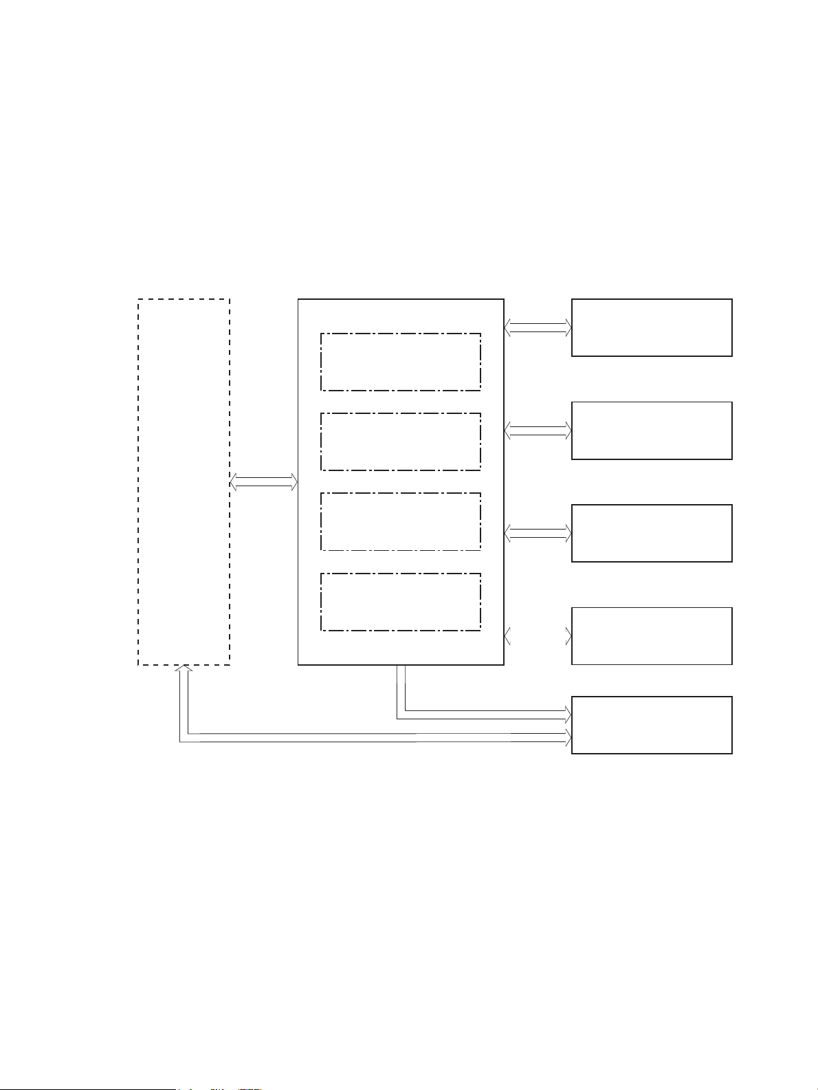
Engine-control system
Output accessory
Formatter
Laser scanner system
Image-formation system
Pickup, feed and delivery
system
DC controller
High-voltage power supply
Fuser control
Low-voltage power supply
Input accessory
Engine-control system
The engine-control system receives commands from the formatter and interacts with the other main systems
to coordinate all printer functions. The engine-control system consists of the following components:
●
DC controller
●
Low-voltage power supply
●
High-voltage power supply
●
Fuser power supply
Figure 1-2 Engine-control system
ENWW Engine-control system 5
Page 32

DC controller
AC input
LED
Transfer roller
High-voltage
power supply
Fan
Cartridge
Sensor
Motor
Clutch
Solenoid
Switch
Photointerrupte
r
Formatter
Control panel
Input accessory
Laser scanner ass’y
Fuser
Low-voltage
power supply
DC controller
Switch
Switch
Clutch
Photointerrupter
Output accessory
The DC controller controls the operation of the printer and its components. The DC controller starts the
printer operation when the printer power is turned on and the power supply sends DC voltage to the DC
controller. After the printer enters the standby period, the DC controller sends out various signals to operate
motors, solenoids, and other printer components based on the print command and image data that the host
computer sends.
Figure 1-3 DC controller
6 Chapter 1 Theory of operation ENWW
Page 33

Motors
The printer has four motors. The motors drive the components in the paper-feed and image-formation
systems.
The DC controller monitors the fuser motor and the drum motor to determine whether a motor has failed. It
noties the formatter when it encounters the following conditions:
●
Startup failure: the motor does not reach a specied speed within a specied time from when the motor
starts.
●
Rotational failure: the rotational speed of the motor is not in the specied range for a specied time
after the motor reaches a specied speed.
Table 1-2 Motors
Abbreviation Name Purpose Failure detection
M1 Fuser motor Drives the pressure roller, fuser output roller,
output roller, duplex switchback roller (duplex
models)
M2 Drum motor Drives the photosensitive drum, primary
charging roller, transfer roller, tray 1 pickup
roller, tray 1 feed roller (M607, M608, M609
models), tray 2 pickup roller, tray 2 feed roller,
registration roller, feed roller, duplex feed
roller (M607dn, M608n/dh/x, M631, M632,
M633 models), each roller for input accessory
M3 Lifter motor Drives the Tray 2 lifter No
M4 Scanner motor Drives the scanner mirror No
Yes
Yes
ENWW Engine-control system 7
Page 34

Fans
The printer has four fans for preventing the temperature from rising in the printer and for cooling the printed
pages.
The DC controller determines whether there is a fan failure and noties the formatter if a fan locks for a
specied time from when the fan starts.
Table 1-3 Fans
Abbreviation Name Cooling area Type Speed
Solenoids
Clutches
FM1 Scanner fan Toner cartridge and laser
scanner assembly
FM2 Duplex fan Duplex feed area Intake Full
FM3 Cartridge upper fan Toner cartridge, laser scanner
assembly, and around the lowvoltage power supply
FM4 Cartridge lower fan Toner cartridge, laser scanner
assembly, and around the lowvoltage power supply
Table
1-4 Solenoids
Component abbreviation Component name
SL1 Tray 1 pickup solenoid
SL2 Developer alienation solenoid
Table
1-5 Clutches
Intake Full
Intake Full/Low
Intake Full/Low
Component abbreviation Component name
CL1 Tray 1 feed clutch (M607, M608, M609 models)
CL2 Duplex feed clutch
CL3 Tray 2 pickup clutch
CL4 Duplex switchback clutch (M607dn, M608dn/x, M609dn/dh/x, M631, M632, M633 models)
Switches
1-6 Switches
Table
Component abbreviation Component name
SW1 24V interlock switch
SW2 Front door switch (M607, M608, M609 models)
8 Chapter 1 Theory of operation ENWW
Page 35

Table 1-6 Switches (continued)
Component abbreviation Component name
SW2 Left door switch (M631, M632, M633 models)
SW4 Tray 2 media size switch 1
SW5 Tray 2 media size switch 2
SW6 Rear door switch R (M607, M608, M609 models)
SW7 Rear door switch L (M607, M608, M609 models)
SW6 Right door switch R (M631, M632, M633 models)
SW7 Right door switch L (M631, M632, M633 models)
SW301 Test print switch
SW4100 Power switch
ENWW Engine-control system 9
Page 36

Photointerrupter sensors
Table 1-7 Photointerrupter sensors
Component abbreviation Component name
PS4300 Tray 2 media out sensor
PS4350 Tray 1 media out sensor
PS4400 Tray 2 media surface sensor
PS4450 FD1 media full sensor
PS4500 Fuser loop sensor
PS4550 Registration sensor
PS4600 separation roller rotation sensor
PS4650 Fuser output sensor
PS4700 Duplex feed sensor (M607dn, M608dn/x, M609dn/dh/x, M631, M632, M633 models)
PS4750 Tray 1 feed sensor (M607, M608, M609 models)
PS4800 Fuser pressure release sensor
PS4850 Developer alienation sensor
Sensors
LEDs
Table
1-8 Sensors
Component abbreviation Component name
TH4200 Environment sensor
Table
1-9 LEDs
Component abbreviation Component name
LED4100 Power supply LED
LED4950 Pre-exposure LED
10 Chapter 1 Theory of operation ENWW
Page 37

Low-voltage power supply
+24VA2
ZEROX
AC input
Low-voltage power supply
Rectifying
circuit
Protection
circuit
+24V
generation
circuit
Fuse
FU2101
Fuse
FU2102
+3.3V
generation
circuit
Fuser
24v interlock switch
SW1
+24VA0
High-voltage power supply
Power switch
SW4101
Fuser control
circuit
Zero crossing
detection circuit
+24VF
+24VA0
FET
+5VA
DC controller
+24VB
+24VA0
+24VA3
+24VC1 +24VC2
FET
FET
FET
FET
+3.3V
generation
circuit
+5VA
+5VD
+5VL
+3.3VA
+3.3VB2
+3.3VC
+3.3VF
+3.3VC
+24VC2
Formatter
+5VE
Fuse
FU605
TP
The low-voltage power supply (LVPS) circuit converts the AC power from the wall receptacle into the DC
voltage that the printer components use.
Figure 1-4 Low-voltage power supply circuits
ENWW Engine-control system 11
Page 38

Low-voltage power supply voltages description
The low-voltage power supply converts the AC power into two DC voltages, which it then subdivides, as
described in the following table:
Table 1-10 Converted DC voltages
Main DC voltage Sub-voltage Behavior
+24V +24VA0 Stopped during active OFF or inactive OFF
+24VA2 Stopped during active OFF or inactive OFF
+24VB Stopped during active OFF or inactive OFF
+24VC1 Stopped during active OFF or inactive OFF
+24VC2 Stopped during active OFF or inactive OFF
+24VF Stopped during active OFF or inactive OFF
+5V +5VA Stopped during inactive OFF
+5VB Stopped during active OFF or inactive OFF
+5VE Stopped during inactive OFF
+5LL Stopped during active OFF or inactive OFF
+3.3V +3.3VA Stopped during inactive OFF
+3.3VB2 Stopped during inactive OFF
+3.3VC Stopped during active OFF or inactive OFF
=3.3VF Stopped during active OFF or inactive OFF
Over-current/over-voltage protection
The low-voltage power supply automatically stops supplying the DC voltage to the printer components
whenever it detects excessive current or abnormal voltage. The low-voltage power supply has a protective
circuit against over-current and over-voltage to prevent failures in the power supply circuit.
CAUTION: If DC voltage is not being supplied from the low-voltage power supply, the protective function
might be running. In this case, turn the power switch o and unplug the power cord.
Supplied intermittently during active OFF
Do not turn the power switch on until the root cause is found and corrected.
If the protective function is active, the DC controller noties the formatter of a low-voltage power supply
failure. In addition, the low-voltage power supply has two fuses to protect against over-current. If overcurrent ows into the AC line, the fuse stops the AC power.
Safety
For personal safety, the printer interrupts +24VB and +24VC power when the cartridge door detection switch
is turned o. This stops DC power supply to the High-voltage power supply (HVPS)
12 Chapter 1 Theory of operation ENWW
Page 39

The printer also stops the +24VB power when the +24V interlock switch is turned o. This stops DC power
supply to the following load:
●
High-voltage power supply
●
Drum motor
●
Fuser motor
●
Duplex switchback clutch (M607dn, M608dn/x, M609dn/dh/x, M631, M632, M633 models)
The remote switch control circuit turns on or o the printer power so that the AC power ows even when the
power switch is turned
o. Unplug the printer power cord before disassembling the printer.
Low-voltage power supply functions
The printer has the following low-voltage power supply functions:
Table 1-11 Low-voltage power supply functions
Function Behavior
Inactive OFF The power supply is o.
Active OFF (state of sleep) The low-voltage power supply
is output only to the formatter
and DC controller.
High-voltage power supply
The DC controller controls the high-voltage power supply (HVPS) to generate biases. The high-voltage power
supply delivers the high-voltage biases to the following components used to transfer toner during the imageformation process:
●
Primary charging roller (in the toner cartridge)
●
Developing roller (in the toner cartridge)
●
Transfer front guide
●
Transfer roller
●
Static charge eliminator
●
Fuser lm
●
Pressure roller
High-voltage power supply circuits
The high-voltage power supply contains the following separate circuits:
ENWW Engine-control system 13
Page 40

Figure 1-5 High-voltage power supply circuits
DEVPRI DIS
TR
TRFRONT
FILM
FUSER
To primary charge roller
To developing roller
Cartridge
Fuser
Transfer roller
Static charge
eliminator
Pressure roller
Fuser film
Transfer front guide
Primary
charging bias
circuit
Developing
bias circuit
Transfer bias
circuit
Fuser bias circuit
Transfer front guide
bias circuit
Static charge
eliminatior
bias circuit
DC controller
High-voltage power supply
Table 1-12 High-voltage power supply circuits
Fuser control
The DC controller and components in the fuser perform the following functions related to fuser operation:
Circuit Description
Primary-charging-bias generation The primary charging bias negatively charges the surface of the photosensitive drum to
prepare for image formation.
Developing-bias generation The developing bias adheres toner to an electrostatic latent image formed on the
Transfer-bias generation The primary transfer bias transfers the toner from the photosensitive drum onto the
Static charge eliminator bias generation The static charge eliminator bias eliminates the electric charge on the back side of the
Fuser bias generation The printer uses instant-on fusing. The fuser bias is DC positive for improved print
photosensitive drum.
paper.
paper for stable paper feed and print quality.
quality. The fuser bias circuit is located in the high-voltage power supply.
14 Chapter 1 Theory of operation ENWW
Page 41

●
FUSER TEMPERATURE signal
FUSER HEATER CONTROL signal
DC controllerLow-voltage power supply
TH1
TP
H1, H2
Pressure roller
Fuser film
Fuser heater
control circuit
Fuser heater
safety circuit
TH3
TH2
●
●
●
●
Fuser circuits
The fuser heater control circuit and the fuser heater safety circuit control the fuser temperature according to
commands from the DC controller. The fuser consists of the following major components:
Figure 1-6 Fuser components
Control fuser temperature
Detect fuser failures
Prevent excessive temperature rise
Detect remaining life in the fuser
Determine if the correct fuser is installed
Table 1-13 Fuser components
Type of component Abbreviation Name Function
Heaters H1, H2 Fuser heaters Heats the center of the fuser lm
Thermistors
(Contact type)
ENWW Engine-control system 15
TH1 Main thermistor Detects the center temperature of
assembly
the fuser heater
Page 42

Table 1-13 Fuser components (continued)
Type of component Abbreviation Name Function
Thermistors
(Contact type)
Thermal switch
(Contact type)
Fuser control functions
The following gure shows the fuser control functions
TH2, TH3 Sum thermistors Detects the edge temperature of the
fuser heater.
TP Thermal fuse Prevents an abnormal temperature
rise in the fuser heater
16 Chapter 1 Theory of operation ENWW
Page 43
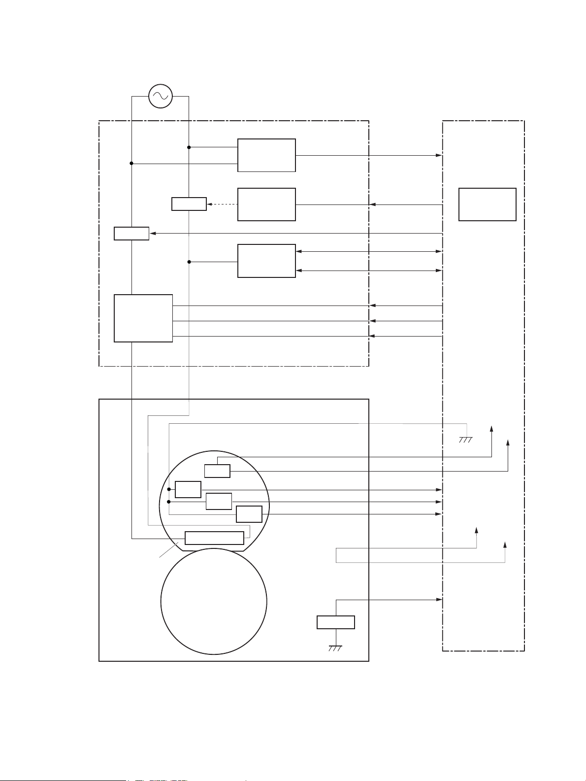
H1, H2
/ZEROX
TP
Fuser film ass’y
Fuser
Pressure roller
RLD
FSAFE
CURCK
Low-voltage suppry supply
Fuser heater
safety circuit
DC controller
Fuser heater
control circuit
Relay control
circuit
Current
detection
circuit
TH1
RL2501
RL2502
AC input
Fuser control
circuit
Zero crossing
detection
circuit
CURRMS
HEAT1
HEAT2
FSAFE3
TH3
TH2
FU7002
FSRNEW
SUBTH1
SUBTH2
MAINTH
+3.3VF0
+3.3VC2
+24VF
+24VC1
Figure 1-7 Fuser control
ENWW Engine-control system 17
The printer has the following fuser-control functions:
Page 44

Table 1-14 Fuser-control functions
Failure detection function Supported feature
Fuser temperature control Yes
Heat up error detection Yes
Low temperature error detection Yes
High temperature error detection Yes
Breaking of a heater wire detection No
Frequency detection circuit failure detection Yes
Low-voltage power supply failure detection Yes
Fuser pressure release mechanism failure detection Yes
Brand new fuser detection Yes
Fuser type discrepancy detection Yes
Fuser type identication detection Yes
Fuser presence detection Yes
Fuser life detection Yes
Fuser roller cleaning Yes
Fuser heater protection
Fuser heater protection is a feature that detects excessive temperatures in the fuser and interrupts the power
supply to the fuser heater.
The following three protective components prevent the fuser heater from excessive rising temperature:
●
DC controller: When a thermistor or sub-thermistor detects a temperature above a certain threshold,
the DC controller interrupts power to the fuser heater.
●
Fuser-heater safety circuit: The fuser heater safety circuit monitors the detected temperature of the
thermistors and interrupts power to the fuser heater when it detects excessive temperature.
●
Temperature fuse: When the fuser heater reaches a temperature above a certain threshold, the
temperature fuse interrupts power to the fuser heater.
18 Chapter 1 Theory of operation ENWW
Page 45

Laser scanner system
Laser ass’y
BD sensor
Scanner mirror
Scanner motor ass’y
Photosensitive drum
DC controller
The laser/scanner system forms the latent electrostatic image on the photosensitive drum inside the toner
cartridge.
The DC controller receives instructions from the formatter regarding the image of the page to be printed. The
DC controller signals the lasers to emit light, and the laser beams pass through lenses and onto the scanner
mirror, which rotates at a constant speed. The mirror reects the beam onto the photosensitive drum in the
pattern required for the image, exposing the surface of the drum so it can receive toner.
The laser/scanner system consists of the following main components:
●
Laser assembly
●
Scanner motor assembly
●
Beam detect (BD) sensor
●
Scanner mirror
Figure 1-8 Laser scanner
ENWW Laser scanner system 19
Page 46

Laser/scanner failure detection
The DC controller determines an optical unit failure and noties the formatter of the error status when any of
the following occur:
●
Laser scanner failure detection
●
Laser/scanner motor startup failure: The scanner motor does not reach a specied rotation frequency
within a specied period of time from when the laser/scanner starts up.
●
Laser/scanner motor abnormal rotation: The laser/scanner motor does not reach a specied rotational
frequency within a
specied period of time during a print operation.
Safety
The laser/scanner assembly has a mechanical laser shutter. For the safety of users and service technicians,
the laser shutter interrupts the optical path of the laser/scanner assembly when the following door is opened:
●
Rear door (SW6, SW7) for M607, M608, M609 models)
●
Right door (SW6, SW7) for M631, M632, M633 models)
20 Chapter 1 Theory of operation ENWW
Page 47
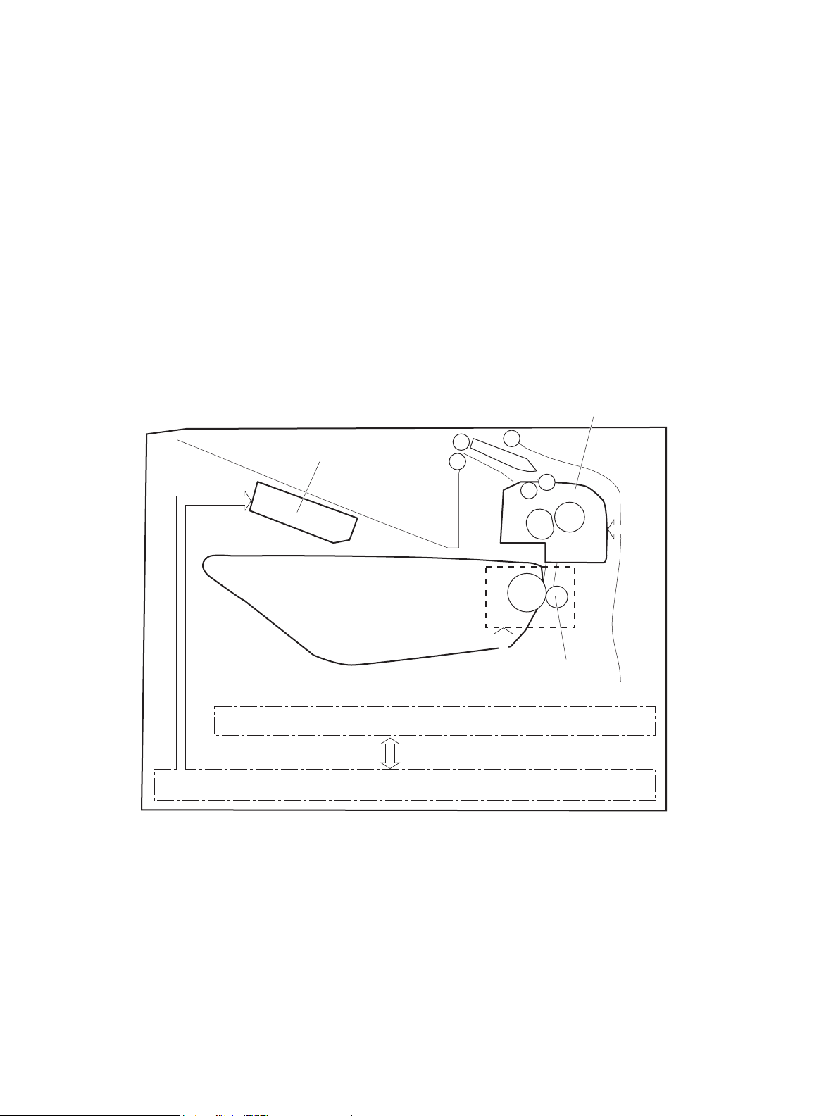
Image formation system
Laser scanner ass’y
Fuser
Cartridge
Transfer roller
High-voltage power supply
DC controller
The image-formation system creates the printed image on the paper. The system consists of the following
components:
●
Toner cartridge
●
Transfer roller
●
Fuser
●
Laser/scanner
●
High-voltage power supply
The DC Controller controls the internal components of the image formation system (according to commands
received from the formatter) to form the toner image on the photosensitive drum surface. The toner image is
then transferred to the print media and fused.
Figure 1-9 Image formation system
The DC controller rotates the following motors to drive each component.
Drum Motor
●
Photosensitive drum
●
●
●
Fuser motor
ENWW Image formation system 21
Developing roller
Primary charging roller (follows the photosensitive drum)
Transfer roller (follows the photosensitive drum)
Page 48

●
SL2
M2 M1
DC controller
Pressure roller
●
Fuser lm (follows the pressure roller)
NOTE: The primary charging roller and developer roller are located in the toner cartridge.
Figure 1-10 Motors
Table 1-15 Motors
Abbreviation Component
M1 Fuser motor
M2 Drum motor
SL2 Developer alienation solenoid
The following gure shows the location of the sensors:
22 Chapter 1 Theory of operation ENWW
Page 49

Figure 1-11 Sensors
PS4850
DC contoller
LED4950
Toner level sensor
Table 1-16 Sensors
Abbreviation Component name
LED4950 Pre-exposure LED
PS4850 Developer alienation sensor
Toner level sensor
ENWW Image formation system 23
Page 50

Image-formation process
7. Fusing
6. Separation
5. Transfer
Latent image formation
3. Laser beam exposure
Developing
4. Developing
Drum cleaning
8. Drum cleaning
1. Pre-exposure
2. Primary charging
Pickup
TransferFusing
Delivery
: Paper path
: Direction of drum rotation
: Functional block
: Step
The image-formation process consists of seven steps divided into ve functional blocks.
Figure 1-12 Image formation process
Table 1-17 Image formation process
Functional block Steps Description
Latent image formation 1. Pre-exposure
Development 4. Developing Toner adheres to the electrostatic latent image on the
Transfer 5. Transfer
Fusing 7. Fusing The toner fuses to the paper to make a permanent
Drum cleaning 8. Drum cleaning Residual toner is removed from the drum.
Step 1: Pre-exposure
To prepare for primary charging, light from the pre-exposure LED strikes the surface of the photosensitive
drum to remove any residual electrical charges from the drum surface.
An invisible latent image forms on the surface of the
photosensitive drum.
2. Primary charging
3. Laser-beam exposure
photosensitive drum.
The toner image transfers to the paper.
6. Separation
image.
24 Chapter 1 Theory of operation ENWW
Page 51

Figure 1-13 Pre-exposure
LED
Photosensitive drum
Primary charging bias
Primary charging roller
Photosensitive drum
Step 2: Primary charging
The primary-charging roller contacts the photosensitive drum and charges the drum with negative potential.
Figure 1-14 Primary charging
ENWW Image formation system 25
Page 52

Step 3: Laser-beam exposure
Photosensitive drum
Laser beam
Developer blade
Developer roller
Developing bias
Photosensitive drum
The laser beam strikes the surface of the photosensitive drum in the areas where the image will form. The
negative charge neutralizes in those areas, which are then ready to accept toner.
Figure 1-15 Laser-beam exposure
Step 4: Development
Toner acquires a negative charge as the developing cylinder contacts the developing blade. Because the
negatively charged surface of the photosensitive drums has been neutralized where the drums have been
struck by the laser beam, the toner adheres to those areas on the drums. The latent image becomes visible on
the surface of each drum.
Figure 1-16 Developing
26 Chapter 1 Theory of operation ENWW
Page 53

Step 5: Transfer
Transfer bias
Photosensitive
drum
Transfer roller
Paper
Transfer front guide bias
Transfer front guide
Paper
Photosensitive
drum
Transfer roller
Static charge eliminator
Static charge
eliminator bias
The toner image on the photosensitive drum transfers to the paper. Transfer bias applied to the transfer roller
attracts the negatively-charged toner to the paper.
Figure 1-17 Transfer
Step 6: Separation
The elasticity of the paper and the curvature of the photosensitive drum cause the paper to separate from the
photosensitive drum. The static-charge eliminator removes excess charge from the paper to make sure that
the toner fuses correctly.
Figure 1-18 Separation
ENWW Image formation system 27
Page 54

Step 7: Fusing
Fuser heater
Paper
Pressure roller
Fuser film
Fuser bias Fuser bias
Brush
Photosensitive
drum
Cleaning blade
Residual toner collection box
To create the permanent image, the paper passes through heated, pressurized rollers to melt the toner onto
the page. Fusing bias is added to the pressure roller to improve the print quality.
Figure 1-19 Fusing
Step 8: Drum cleaning
The cleaning blade scrapes the residual toner o the surface of the photosensitive drum, and toner is
deposited in the toner-collection portion of the cartridge.
Figure 1-20 Drum cleaning
28 Chapter 1 Theory of operation ENWW
Page 55

Toner cartridge
Developer roller
M2
PS4850
DC controller
Primary charging roller
Cartridge
E-label
Photosensitive drum
SL2
Toner level sensor
The printer has one toner cartridge.
Design
The toner cartridge is lled with toner and consists of the following components:
●
Photosensitive drum
●
Developer roller
●
Primary-charging roller
●
E-label
The DC controller rotates the drum motor to drive the photosensitive drum, developer roller, and the primarycharging roller.
Figure 1-21 Toner cartridge components
Table 1-18 Toner cartridge functions
Function Supported feature
Toner cartridge presence detection Yes
Toner level detection Yes
Toner cartridge life detection Yes
Toner cartridge mis-installation detection No
Drum discharge Yes
Developer alienation control Yes
Toner level sensor mechanism malfunction No
Transfer roller cleaning Yes
Primary charging roller cleaning No
ENWW Toner cartridge 29
Page 56

Pickup, feed, and delivery system
The DC controller controls the pickup, feed, and delivery system according to commands from the formatter.
The pickup, feed, and delivery system uses a series of rollers to move the paper through the printer.
The pickup, feed, and delivery system consists of the following three functional blocks. The DC controller
controls each block to pick up, feed, and deliver the paper.
●
Pickup-and-feed block: Controls the movement of the paper from each pickup source to the fuser inlet
●
Fuser-and-delivery block: Controls the movement of the paper from the fuser to the delivery
destination
●
Duplex block: Controls the movement of the paper from the duplex switchback unit to the duplex repickup unit (M607dn, M608dn/x, M609dn/dh/x, M631, M632, M633 models)
The following gure shows the simplex and duplex paper path for the pickup, feed, and delivery system:
30 Chapter 1 Theory of operation ENWW
Page 57
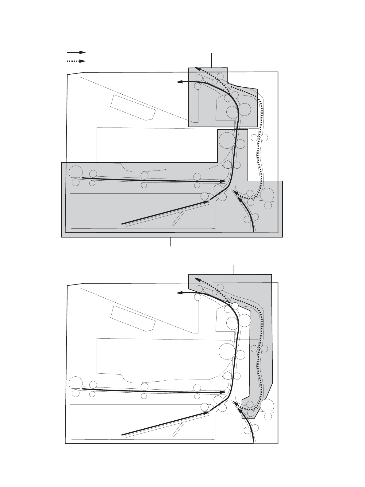
Figure 1-22 Pickup, feed, and delivery system
Duplex paper path
Simplex paper path
Duplex block
Pickup-and-feed block
Fuser-and-delivery block
ENWW Pickup, feed, and delivery system 31
Page 58

Table 1-19 Pickup, feed, and delivery functions
Function Supported feature
Tray 2 media size detection Yes
Tray 2 presence detection Yes
Tray 2 media surface detection Yes
Tray 2 media presence detection Yes
Tray 2 media level detection No
Tray 2 lift-up control Yes
Tray 2 lift-down control No
Tray 2 multiple-feed prevention mechanism Yes
Tray 1 media presence detection Yes
Tray 1 media width detection No
Tray 1 last-media detection No
Skew-feed prevention mechanism Yes
Feed speed control (M607dn, M608dn/x, M609dn/dh/x, M631, M632,
M633 models)
Loop control Yes
Media detection No
OHT detection No
Image leading edge positioning Yes
Media length detection Yes
Media width detection Yes
Pressure roller pressure release control No
Output bin media-full detection Yes
Automatic delivery Yes
Duplex switchback control (M607dn, M608dn/x, M609dn/dh/x, M631,
M632, M633 models)
Duplex feed control (M607dn, M608dn/x, M609dn/dh/x, M631, M632,
M633 models)
Yes
Yes
Yes
32 Chapter 1 Theory of operation ENWW
Page 59

Photo sensors and switches
PS4350
M607/M608/M609 only
SW4 SW5
PS4300
PS4400
M631/M632/M633 only
PS4350
PS4750
PS4700
PS4550
PS4500
PS4650
PS4450
PS4600
The following gure shows the photo sensors and switches for the pickup, feed, and delivery system:
Figure 1-23 Photo sensors and switches
Table 1-20 Photo sensors and switches
Abbreviation Component
PS4300 Tray 2 media out sensor
PS4350 Tray 1 media out sensor
PS4400 Tray 2 media surface sensor
PS4450 FD1 media full sensor
PS4500 Fuser loop sensor
PS4550 Registration sensor
PS4600 separation roller rotation sensor
PS4650 Fusor output sensor
PS4700 Duplex feed sensor (M607dn, M608dn/x, M609dn/dh/x, M631, M632, M633 models)
PS4750 Tray 1 feed sensor (M607, M608, M609 models)
SW4 Tray 2 media size switch 1
SW5 Tray 2 media size switch 2
ENWW Pickup, feed, and delivery system 33
Page 60
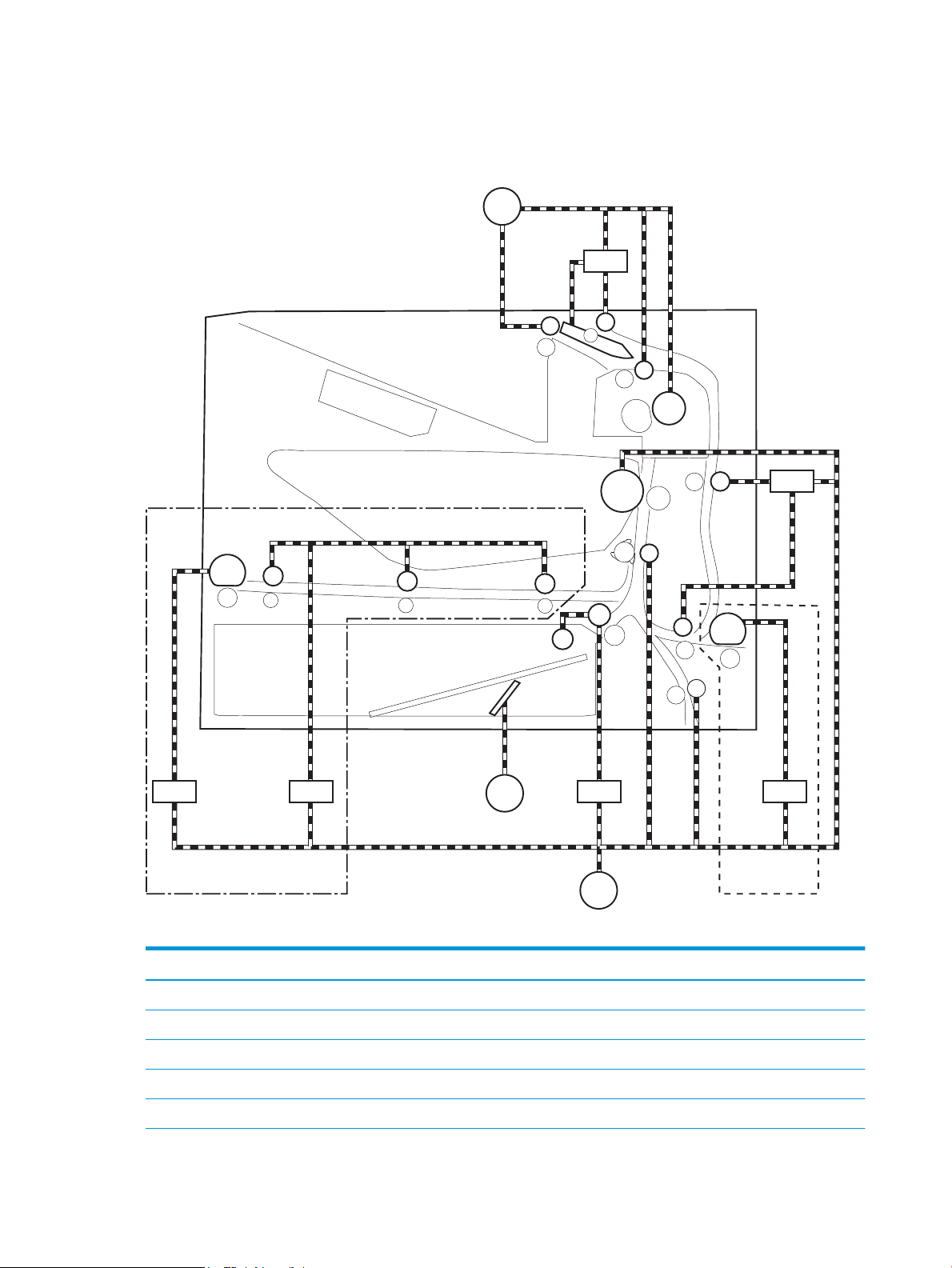
Motors, clutches, and solenoids
M607/M608/M609 only M631/M632/M633 only
M1
CL4
CL2
SL1
M2
CL3
M3
SL1 CL1
The following gure shows the motors, clutches, and solenoids for the pickup, feed, and delivery system:
Figure 1-24 Motors, solenoids, and clutches for pickup, feed and delivery system
Table 1-21 Motors, solenoids, and clutches
Abbreviation Component
M1 Fuser motor
M2 Drum motor
M3 Lifter motor
SL1 Tray 1 pickup solenoid
CL1 Tray 1 feed clutch (M607, M608, M609 models)
34 Chapter 1 Theory of operation ENWW
Page 61

Table 1-21 Motors, solenoids, and clutches (continued)
Abbreviation Component
CL2 Duplex feed clutch (M607dn, M608dn/x, M609dn/dh/x, M631, M632, M633 models)
CL3 Tray 2 pickup clutch
CL4 Duplex switchback clutch (M607dn, M608dn/x, M609dn/dh/x, M631, M632, M633 models)
Jam detection/prevention
The printer uses sensors to detect the paper as it moves through the paper path and to report to the DC
controller if the paper has jammed.
The following gure shows the location of the sensors in the paper path:
ENWW Pickup, feed, and delivery system 35
Page 62
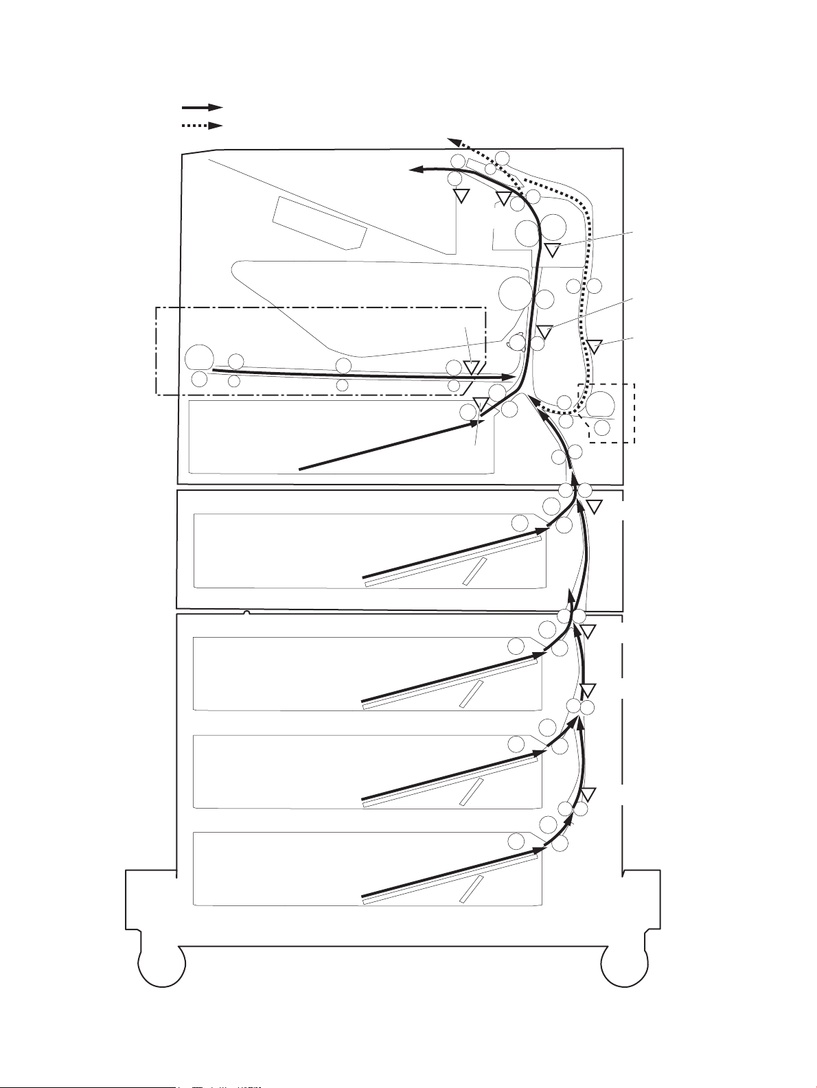
Figure 1-25 Paper path and location of sensors
PS4550
Duplex paper path
Simplex paper path
PS4400
PS4750
PS4700
PS4500
PS4650
PS3401
PS4501
PS5601
PS3601
M607/M608/M609 only
M631/M632/M633 only
PS4450
36 Chapter 1 Theory of operation ENWW
Page 63

Table 1-22 Paper path sensors
Abbreviation Component
PS3401 Paper deck tray 1 feed sensor/HCI feed sensor (1x550-sheet paper deck, 3x550-sheet paper deck, 2,550-sheet
PS3601 PF feed sensor (550-sheet paper feeder and envelope feeder)
PS4400 Tray 2 media surface sensor
PS4450 FD1 media full sensor
PS4500 Fuser loop sensor
PS4501 Paper deck Tray 2 feed sensor (3x550-sheet paper deck and 2,550-sheet paper deck)
PS4550 Registration sensor
PS4650 Fuser output sensor
PS4700 Duplex feed sensor (M607dn, M608dn/x, M609dn/dh/x, M631, M632, M633 models)
PS4750 Tray 1 feed sensor (M607, M608, M609 models)
PS5601 Paper deck Tray 3 feed sensor (3x550-sheet paper deck)
paper deck, and 2,100-sheet paper deck)
The printer determines that a jam has occurred if one of the sensors detects paper at an inappropriate time.
The DC controller stops the print operation and noties the formatter.
Table
1-23 Jams that the printer detects
Jam
No pick jam 1
No pick jam 2
No pick jam 3
Pickup stay jam1
Fuser delivery delay jam 1
Fuser deliver stay jam 1
Residual paper jam 1
Residual paper jam 2
Door open jam 1
Fuser wrap jam 1
Duplex re-pickup jam 1
Delivery delay jam 1
Duplex feed delay jam 1
Inappropriate to the delivery path jam 2
ENWW Pickup, feed, and delivery system 37
Page 64

Input accessories
Clutch
Switch
Photointerruptor
DC controller
Paper feeder controller
+3.3VB
+24VA
Motor
550-sheet paper feeder/envepole feeder
Optional input accessories are available for the printer:
Models Accessories
M607, M608, M609 550-sheet paper feeder
M631, M632,M633 550-sheet paper feeder
550-sheet paper feeder (PF)
The 550-sheet paper feeder (PF) is installed under the printer. It picks up paper and feeds it into the printer.
Controller
Envelope feeder
2,100-sheet paper deck (HCI)
Envelope feeder
1x550-sheet paper deck
3x550-sheet paper deck
2,550-sheet paper deck
The paper feeder controller controls the operational sequence of the paper feeder.
Figure 1-26 Controller for the 550-sheet PF
Paper path
The following gure shows the paper path when the 550-sheet paper feeder is installed:
38 Chapter 1 Theory of operation ENWW
Page 65
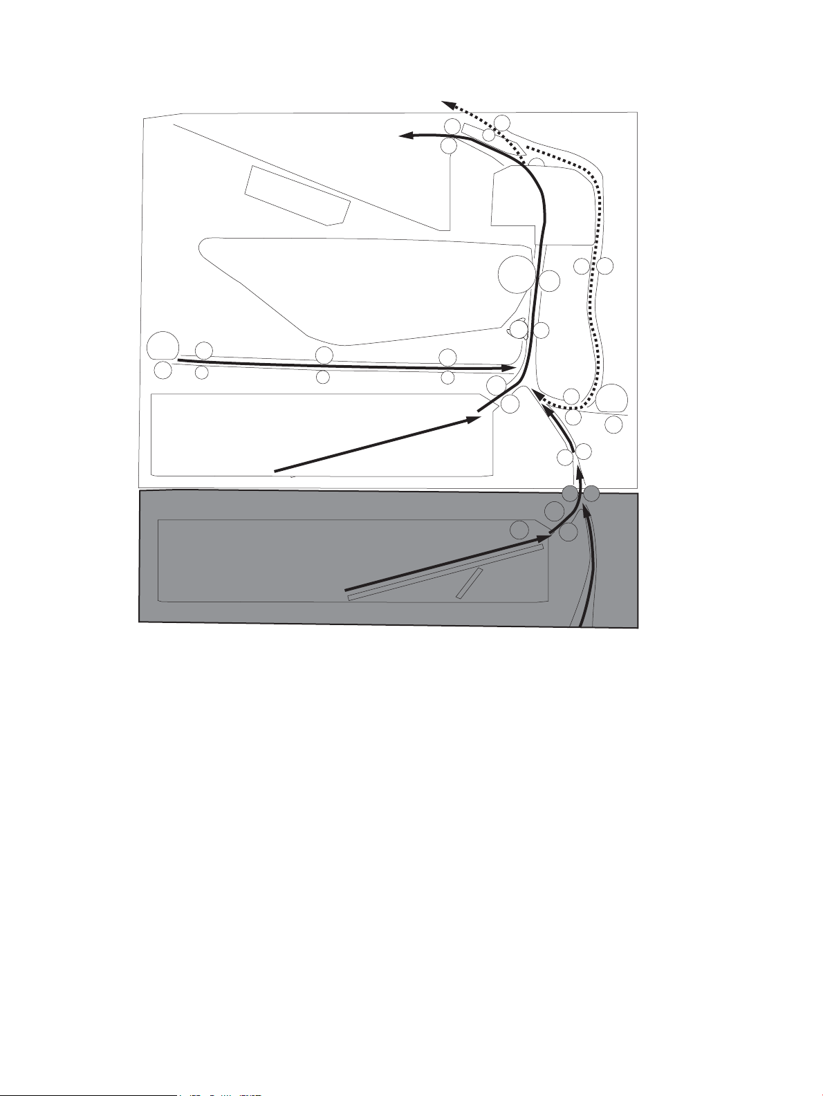
Figure 1-27 Paper path for the 550-sheet PF
Pickup and feed components
The 550-sheet paper feeder has one motor for lifting the tray and feeding paper.
ENWW Input accessories 39
Page 66

Figure 1-28 Pickup and feed components for the 550-sheet PF
PS900
PS3601
PS3602
M2
CL3602
CL3601
PS3603
M3601
SW3601 SW3602
Table 1-24 Pickup and feed components for the 550-sheet PF
Component type Abbreviation Component name
Motors M2 Drum motor (included in the printer)
1
M3601
Clutches CL3601 PF pickup clutch
CL3602 PF feed clutch
Switches SW3601 PF media size switch 1
SW3602 PF media size switch 2
SW3603 PF door switch
Sensors PS3601 PF feed sensor
PS3602 PF media out sensor
PS3603 PF media surface sensor
PS900 PF separation roller rotation sensor
1
The paper feeder does not detect motor failure
Table
1-25 Pickup and feed functions for the 550-sheet PF
Function Supported feature
Tray lift-up control Yes
PF lifter motor (lifts the tray)
Tray presence detection Yes
Tray media size detection Yes
Tray media stack surface detection Yes
40 Chapter 1 Theory of operation ENWW
Page 67

Table 1-25 Pickup and feed functions for the 550-sheet PF (continued)
Function Supported feature
Tray media out detection Yes
Tray media level detection No
Multiple-feed prevention Yes
Automatic delivery Yes
ENWW Input accessories 41
Page 68

Jam detection
Clutch
Switch
Photointerruptor
DC controller
HCI controller
+3.3VB
+24VA
Motor
2100-sheet paper deck
The printer DC controller detects jams during pickup or feed from the 550-sheet paper feeder.
2,100-sheet paper deck (HCI)
The 2,100-sheet HCI (high capacity input) paper deck is an optional accessory for the following models: M607,
M608, and M609.
The HCI paper deck is installed under the printer. It picks up paper and feeds it into the printer.
Controller
The HCI controller controls the operational sequence of the HCI.
Figure 1-29 Controller for the 2,100-sheet HCI
Paper path
The following gure shows the paper path when the 2,100-sheet HCI is installed:
42 Chapter 1 Theory of operation ENWW
Page 69

Figure 1-30 Paper path for the 2,100-sheet HCI
Pickup and feed components
The HCI paper deck has one motor for lifting the tray and feeding paper.
ENWW Input accessories 43
Page 70

Figure 1-31 Pickup and feed components for the 2,100-sheet HCI
PS900a
M2
CL3402
CL3401
SW3403
PS3402
SW3402
SW3401
M3401
PS3401
PS3403
Table 1-26 Pickup and feed components for the 2,100-sheet HCI
Component type Abbreviation Component
Motors M2 Drum motor (included in the printer
Clutches CL3401 HCI pickup clutch
Switch SW3401 HCI media size switch
Photointerrupter PS3401 HCI feed sensor
1
M3401
1
HCI lifter motor (lifts up the tray)
CL3602 HCI feed clutch
SW3402 HCI front door switch
SW3403 HCI rear door switch
PS3402 HCI media out sensor
PS3403 HCI media surface sensor
PS900a HCI separation roller rotation sensor
44 Chapter 1 Theory of operation ENWW
Page 71

Table 1-27 Paper pickup and feed functions for the 2,100-sheet HCI
Function Supported feature
HCI Lift-up control Yes
HCI presence detections Yes
HCI media size detection Yes
HCI media stack surface detection Yes
HCI media out detection Yes
HCI media level detection No
Multiple-feed prevention Yes
Automatic delivery Yes
ENWW Input accessories 45
Page 72

Jam detection
Clutch
Switch
Photointerruptor
DC controller
Paper deck controller
+3.3VB
+24VA
Motor
1x550-sheet paper deck/3x550-sheet paper deck/2550-sheet paper deck
The printer DC controller detects jams during pickup or feed from the HCI paper deck.
1x550, 3x550, 2,550-sheet paper decks (PD)
The 1x.550, 3x550, and 2,100-sheet paper decks are optional accessories for the following models: M631,
M632, and M633.
The paper deck is installed under the printer. It picks up paper and feeds it into the printer.
Controller
The paper deck controller controls the operational sequence of the paper deck.
Figure 1-32 Controller for the 1x550, 3x550, and 2,550 paper decks
Paper path
The following gures show the paper path for the 1x550, 3x550, and 2,550 paper decks:
46 Chapter 1 Theory of operation ENWW
Page 73
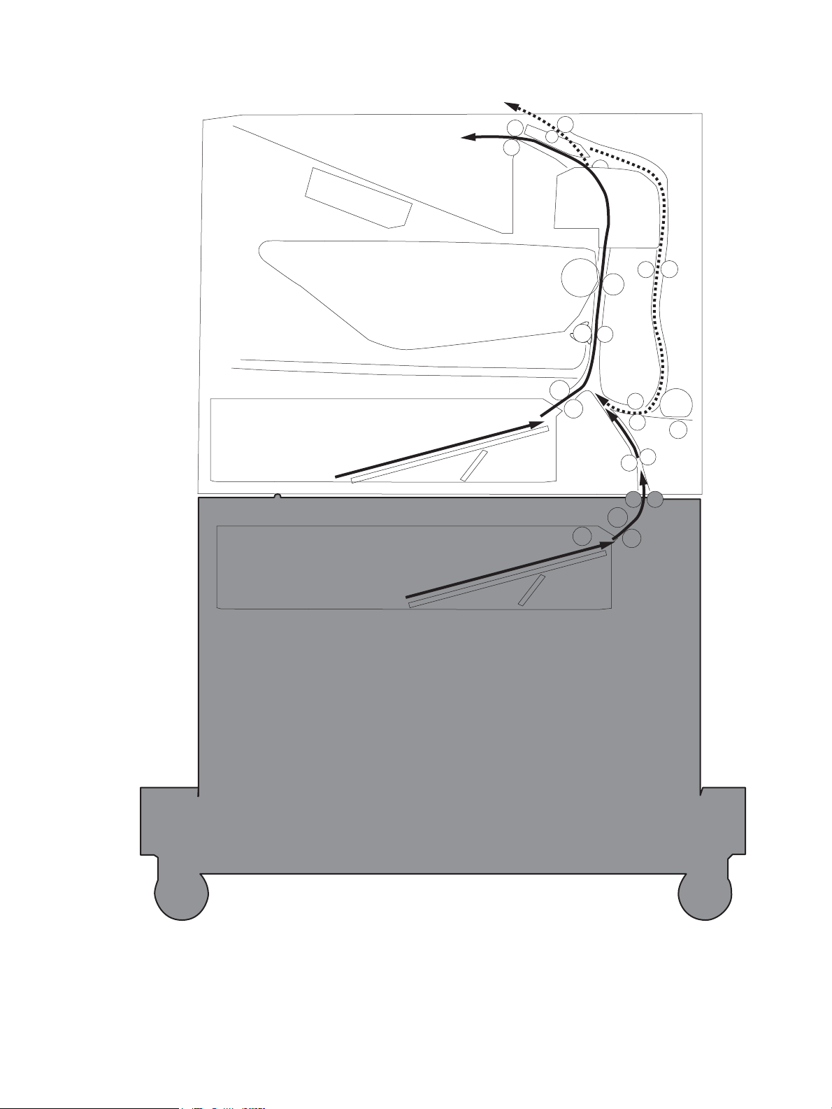
Figure 1-33 Paper path for the 1x550 PD
ENWW Input accessories 47
Page 74

Figure 1-34 Paper path for the 3x550 PD
48 Chapter 1 Theory of operation ENWW
Page 75
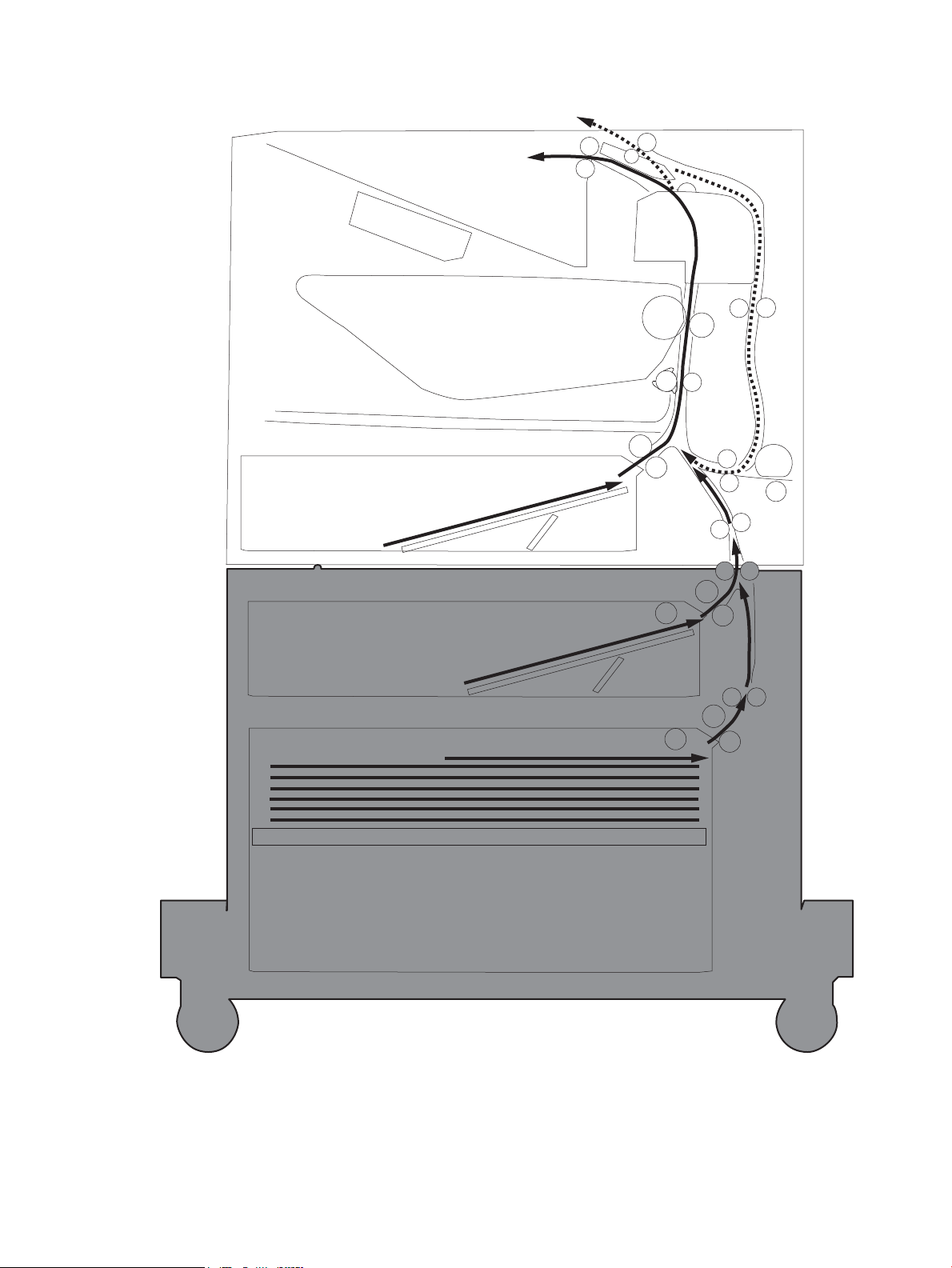
Figure 1-35 Paper path for the 2,550 PD
Pickup and feed components
The paper deck picks up the sheet of paper in the HCI tray and feeds it to the printer. Each paper deck has one
motor for lifting up the cassette.
ENWW Input accessories 49
Page 76

Figure 1-36 Pickup and feed components for 1x550 paper deck and 3x550 paper deck
PS900a
M2
CL3401
CL3402
SW3403
PS3402
SW3401 SW3402
M3401
PS3401
PS3403
SW4501 SW4502
SW5601 SW5602
M4501
M5601
PS900b
PS4502
PS900c
PS5602
PS4503
PS5603
PS4501
PS5601
CL4502
CL5602
CL4501
CL5601
Table 1-28 Pickup and feed components for 1x550 paper deck and 3x550 paper deck
Component type Abbreviation Component 1x550 3x550
Motor M2 Drum motor (included in printer) No No
Clutch CL3401 PD tray 1 pickup clutch Yes Yes
Switch SW3401 PD tray 1 media size switch 1 Yes Yes
1
M3401
1
M4501
1
M5601
CL3402 PD tray 1 feed clutch Yes Yes
PD tray 1 lifter motor Yes Yes
PD tray 2 lifter motor No Yes
PD tray 3 lifter motor No Yes
CL4501 PD tray 2 pickup clutch No Yes
CL4502 PD tray 2 feed clutch No Yes
CL5601 PD tray 3 pickup clutch No Yes
CL5602 PD tray 3 feed clutch No Yes
SW3402 PD tray 1 media size switch 2 Yes Yes
SW4501 PD tray 2 media size switch 1 No Yes
SW4502 PD tray 2 media size switch 2 No Yes
50 Chapter 1 Theory of operation ENWW
Page 77

Table 1-28 Pickup and feed components for 1x550 paper deck and 3x550 paper deck (continued)
Component type Abbreviation Component 1x550 3x550
SW5601 PD tray 3 media size switch 1 No Yes
SW5602 PD tray 3 media size switch 2 No Yes
SW3403 PD door switch Yes Yes
Sensor PS3401 PD tray 1 feed sensor Yes Yes
PS3402 PD tray 1 media out sensor Yes Yes
PS3403 PD tray 1 media surface sensor Yes Yes
PS4501 PD tray 2 feed sensor No Yes
PS4502 PD tray 2 media out sensor No Yes
PS4503 PD tray 2 media surface sensor No Yes
PS5601 PD tray 3 feed sensor No Yes
PS5602 PD tray 3 media out sensor No Yes
PS5603 PD tray 3 media surface sensor No Yes
PS900a PD separation roller rotation sensor 1Yes Yes
PS900b PD separation roller rotation sensor 21No Yes
PS900c PD separation roller rotation sensor 31No Yes
1
ENWW Input accessories 51
Page 78
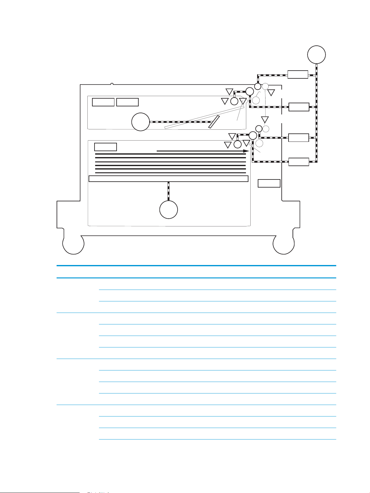
Figure 1-37 Pickup and feed components for the 2,550-sheet paper deck
PS900a
M2
CL3401
CL3402
SW3403
PS3402
SW3401 SW3402
M3401
PS3401
PS3403
SW4501
M4501
PS900b
PS4502
PS4503
PS4501
CL4502
CL4501
Table 1-29 Pickup and feed components for the 2,550-sheet paper deck
Component type Abbreviation Component
Motor M2 Drum motor (included in the printer)
Clutch CL3401 PD tray 1 pickup clutch
Switch SW3401 PD tray 1 media size switch 1
Sensor PS3401 PD tray 1 feed sensor
M3401 PD tray 1 lifter motor
M4501 PD tray 2 lifter motor
CL3402 PD tray 1 feed clutch
CL4501 PD tray 2 pickup clutch
CL4502 PD tray 2 feed clutch
SW3402 PD tray 1 media size switch 2
SW4501 PD tray 2 media size switch 1
SW3403 PD door switch
PS3402 PD tray 1 media out sensor
PS3403 PD tray 1 media surface sensor
52 Chapter 1 Theory of operation ENWW
Page 79

Table 1-29 Pickup and feed components for the 2,550-sheet paper deck (continued)
Component type Abbreviation Component
PS4501 PD tray 2 feed sensor
PS4502 PD tray 2 media out sensor
PS4503 PD tray 2 media surface sensor
PS900a PD separation roller rotation sensor 1
PS900b PD separation roller rotation sensor 2
Table 1-30 Pickup and feed functions for the 1x550, 3x550, and 2,550 paper decks
Function Supported feature
tray lift-up control Yes
tray presence detection Yes
tray media size detection Yes
tray media stack surface detection Yes
tray media out detection Yes
tray media level detection No
Multiple-feed prevention Yes
Automatic delivery Yes
Paper deck jam detection
The printer DC controller detects jams during pickup or feed from the paper deck.
ENWW Input accessories 53
Page 80

Output accessories
Clutch
Switch
Photointerruptor
DC controller
SSMBM controller
+5VB
+24VA
Motor
SSMBM
Fotmatter
Fan
An optional 2-bin or 5-bin staple stacker multi bin mailbox (SSMBM) is available for the printer.
Models Supported SSMBM
M631, M632, M633 2-bin SSMBM
M607, M608, M609 5-bin SSMBM
2-bin staple stacker multi-bin mailbox (SSMBM)
The 2-bin (SSMBM) is available for the M631, M632, and M633 models. It is installed above the printer and
delivers the paper to the output tray after stapling.
Controller
The SSMBM controller controls the operation sequence of the SSMBM.
Figure 1-38 SSMBM controller
Paper path
The following gure shows the paper path for the 2-bin SSMBM:
54 Chapter 1 Theory of operation ENWW
Page 81

Figure 1-39 Paper path for the 2-bin SSMBM
Motors
The 2-bin SSMBM has six motors for the paper feed, paper alignment, and stapling.
ENWW Output accessories 55
Page 82

Fan
Table 1-31 Motors for the 2-bin SSMBM
Component Components driven
M11 SS output motor Output bin 1 delivery roller, exit feed roller
M12 SS feed motor Output bin 2 delivery roller, inlet feed roller
M14 Jogger motor Jogger guide
M15 Y alignment motor Alignment roller
Engages/disengages the output in 1
delivery order
M16 Staple motor Staple
M17 Lifter motor Lift up the output bin 1
NOTE: The SSMBM does not detect motor failures.
The SSMBM has a fan that prevents the temperature from rising in the SSMBM. The SSMBM controller detects
fan failure.
Table
1-32 Fan for the 2-bin SSMBM
Component Cooling area Type Speed
Fan11 MBM fan Inside the SSMBM Intake Full/Low
Delivery functions
Table
1-33 Delivery functions for the SSMBM
Function Supported feature
Mailbox mode Yes
Stacker mode No
Function separator mode No
Job separator mode No
Collator mode No
Staple control Yes
Automatic delivery Yes
Delivery operation
The SSMBM delivers paper from the printer to the specied output bin for each print job (mailbox mode).
56 Chapter 1 Theory of operation ENWW
Page 83

Figure 1-40 Motors and solenoids for the 2-bin SSMBM
M14
M12
SL11
SL13
M17
M15
SL12
M11
Table 1-34 Motors and solenoids for the 2-bin SSMBM
Abbreviation Component
M11 SS output motor
M12 SS feed motor
M14 Jogger motor
M15 Y alignment motor
M16 Staple motor
M17 Lifter motor
SL11 Inlet apper solenoid
SL12 Stamp solenoid
SL13 Output bin 2 apper solenoid
ENWW Output accessories 57
Page 84

Figure 1-41 Sensors and switches for the 2-bin SSMBM
PS110
PS108
PS109
PS101
PS105
PS112
PS111
PS102
PS103
PS113
PS114
PS115
PS107
PS106
PS104
SW2
SW11
Table 1-35 Sensors and switches for the 2-bin SSMBM
Abbreviation Component
PS101 Bin 1 media presence sensor
PS102 SS exit sensor
PS103 Staple inlet sensor
PS104 Y alignment home position sensor
PS105 Bin 1 media full sensor
PS106 Alienation home position sensor
PS107 Jogger home position sensor
PS108 Bin 2 media presence sensor
PS109 Bin 2 media full sensor
PS110 SS inlet sensor
PS111 Bin 1 upper limit sensor
PS112 Bin 1 lower limit sensor
PS113 Staple low sensor
PS114 Staple ready sensor
PS115 Staple home position sensor
SW2 SS door switch
SW11 Staple door switch
58 Chapter 1 Theory of operation ENWW
Page 85

Jam detection
The SSMBM detects the following types of jams:
●
●
●
The 2-bin SSMBM uses the following sensors to detect the presence of the paper and to check whether the
paper is being fed correctly.
●
●
●
Residual paper jam
Feed delay jam
Feed stay jam
SS exit sensor (PS102)
Staple inlet sensor (PS103)
SS inlet sensor (PS110)
ENWW Output accessories 59
Page 86

Figure 1-42 Paper path and location of sensors for the 2-bin SSMBM
PS102
PS103
PS110
5-bin staple stacker multi bin mailbox (SSMBM)
The 5-bin (SSMBM) is available for the M607, M608, and M609 models. It: is installed above the printer and
delivers the paper to the output tray after stapling.
60 Chapter 1 Theory of operation ENWW
Page 87
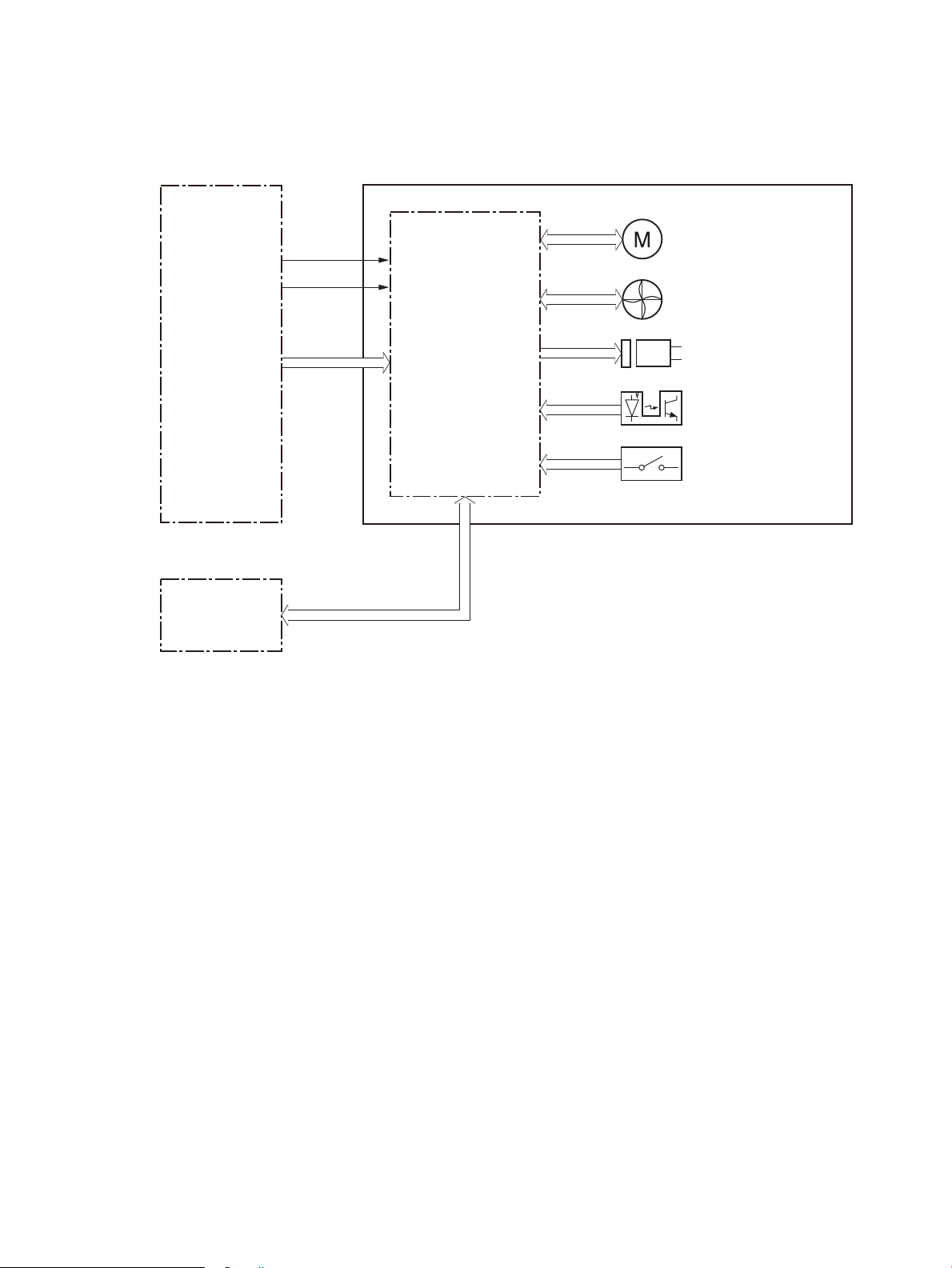
Controller
Clutch
Switch
Photointerruptor
DC controller
SSMBM controller
+5VB
+24VA
Motor
SSMBM
Fotmatter
Fan
The SSMBM controller controls the operation sequence of the SSMBM.
Figure 1-43 SSMBM controller
Paper path
The following gure shows the paper path for the 5-bin SSMBM
ENWW Output accessories 61
Page 88
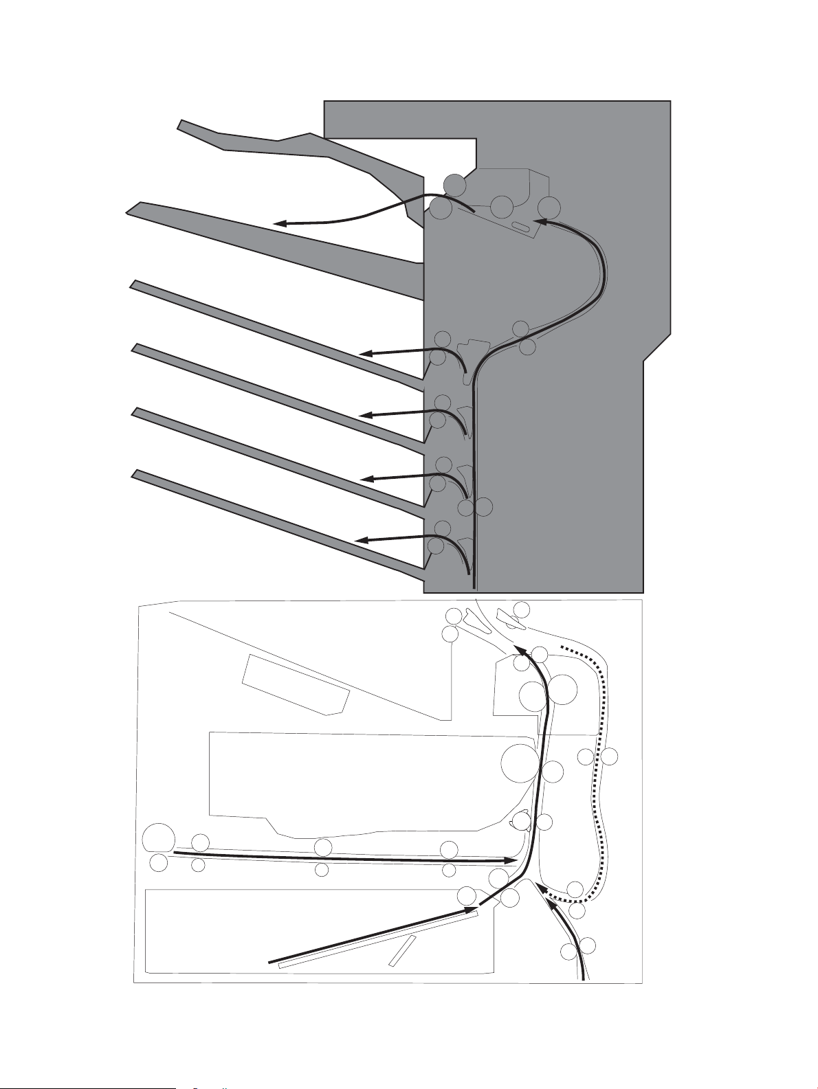
Figure 1-44 Paper path for the 5-bin SSMBM
62 Chapter 1 Theory of operation ENWW
Page 89

Motors
The 5-bin SSMBM has six motors for the paper feed, paper alignment, and stapling.
Table 1-36 Motors for the 5-bin SSMBM
Component Components driven
M11 SS output motor Output bin 1 delivery roller, exit feed roller
M12 SS feed motor Output bin 2 delivery roller, inlet feed roller
M13 MBM feed motor Output bin 3 delivery roller, output bin 4 delivery
roller, output bin 5 delivery roller, feed roller
M14 Jogger motor Jogger guide
M15 Y alignment motor Alignment roller
Engages/disengages the output in 1 delivery order
M16 Staple motor Staple
M17 Lifter motor Lift up the output bin 1
NOTE: The SSMBM does not detect motor failures.
Fan
The SSMBM has a fan that prevents the temperature from rising in the SSMBM. The SSMBM controller detects
fan failure
Table
1-37 Fan for SSMBM
Component Cooling area Type Speed
Fan11 MBM fan Inside the SSMBM Intake Full/Low
Delivery functions
Table
1-38 Delivery functions for the SSMBM
Function Supported feature
Mailbox mode Yes
Stacker mode No
Function separator mode No
Job separator mode No
Collator mode No
Staple control Yes
Automatic delivery Yes
ENWW Output accessories 63
Page 90
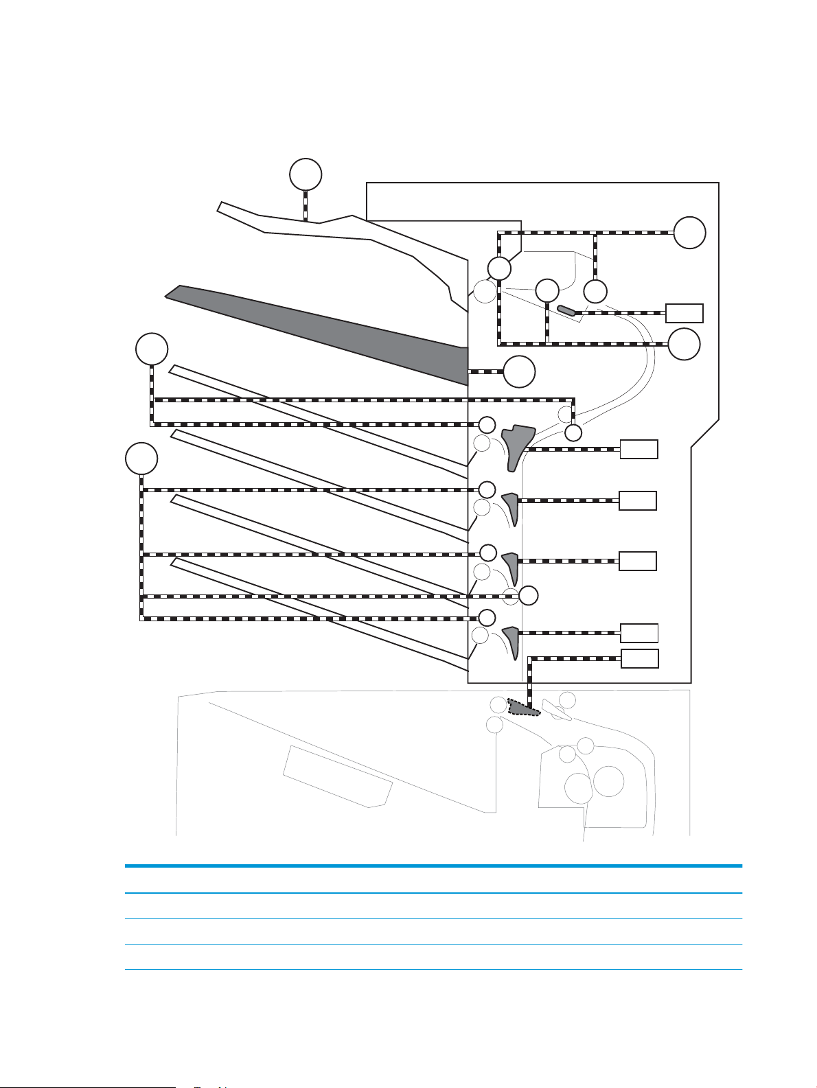
Delivery operation
M14
M12
M13
SL11
SL16
SL15
SL14
SL13
M17
M15
SL12
M11
The SSMBM delivers paper from the printer to the specied output bin for each print job (mailbox mode).
Figure 1-45 Motors and solenoids for the 5-bin SSMBM
Table 1-39 Motors and solenoids for the 5-bin SSMBM
Abbreviation Component
M11 SS output motor
M12 SS feed motor
M13 MBM feed motor
64 Chapter 1 Theory of operation ENWW
Page 91

Table 1-39 Motors and solenoids for the 5-bin SSMBM (continued)
PS119
PS122
PS118
PS121
PS117
PS120
PS116
PS110
PS108
PS109
PS101
PS105
PS112
PS111
PS102
PS103
PS113
PS114
PS115
PS107
PS106
PS104
SW1
SW2
SW11
Abbreviation Component
M14 Jogger motor
M15 Y alignment motor
M16 Staple motor
M17 Lifter motor
SL11 Inlet apper solenoid
SL12 Stamp solenoid
SL13 Output bin 2 apper solenoid
SL14 Output bin 3 apper solenoid
SL15 Output bin 4 apper solenoid
SL16 Output bin 5 apper solenoid
Figure 1-46 Sensors and switches for the 5-bin SSMBM
ENWW Output accessories 65
Page 92

Table 1-40 Sensors and switches for the 5-bin SSMBM
Abbreviation Component
PS101 Bin 1 media presence sensor
PS102 SS exit sensor
PS103 Staple inlet sensor
PS104 Y alignment home position sensor
PS105 Bin 1 media full sensor
PS106 Alienation home position sensor
PS107 Jogger home position sensor
PS108 Bin 2 media presence sensor
PS109 Bin 2 media full sensor
PS110 SS inlet sensor
PS111 Bin 1 upper limit sensor
PS112 Bin 1 lower limit sensor
PS113 Staple low sensor
PS114 Staple read sensor
PS115 Staple home position sensor
PS116 Bin 3 media full sensor
PS117 Bin 4 media full sensor
PS118 Bin 5 media full sensor
PS119 MBM inlet sensor
PS120 Bin 3 media presence sensor
PS121 Bin 4 media presence sensor
PS122 Bin 5 media presence sensor
SW1 MBM door switch
SW2 SS door switch
SW11 Staple door switch
Jam detection
The SSMBM detects the following types of jams:
●
●
Residual paper jam
Feed delay jam
●
Feed stay jam
The 5-bin SSMBM uses the following sensors to detect the presence of the paper and to check whether the
paper is being fed correctly.
66 Chapter 1 Theory of operation ENWW
Page 93

●
SS exit sensor (PS102)
●
Staple inlet sensor (PS103)
●
SS inlet sensor (PS110)
●
MBM inlet sensor (PS119)
ENWW Output accessories 67
Page 94
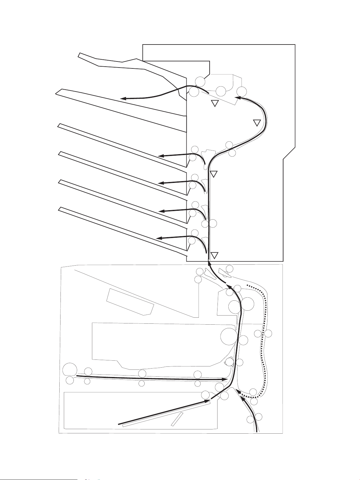
Figure 1-47 Paper path and location of sensors for the 5-bin SSMBM
PS103
PS102
PS110
PS119
68 Chapter 1 Theory of operation ENWW
Page 95

Scanning and image capture system (M631, M632, M633)
NOTE: This section is for the M631, M632, and M633 printers only.
The scanner is a carriage-type platen scanner which includes the frame, glass, scan module, and a scan
control board (SCB). The scanner has a sensor to detect legal-sized media and a switch to indicate when the
document feeder is opened.
The document feeder and control panel are attached to the scanner. If the scanner fails, it can be replaced as
a whole unit. The scanner replacement part does not include the document feeder, control panel, or SCB.
ENWW Scanning and image capture system (M631, M632, M633) 69
Page 96

Document feeder system (M631, M632, M633)
NOTE: This section is for the M631, M632, and M633 printers only.
Document feed system
This section describes the following:
●
Sensors in the document feeder
●
Document feeder paper path
●
Simplex single-pass scanning
●
Electronic duplexing (e-duplex) single-pass scanning
●
Deskew operation
●
Document feeder hinges
The printer supports single-pass electronic duplexing (e-duplex) copy jobs. Two separate scan modules scan
the front-side and back-side of an e-duplex copy job page in a single pass through the document feeder.
For the WF class, this ADF supports a smart background which auto-crops and adjusts the image extents.
Sensors in the document feeder
The document feeder contains the following sensors:
●
ADF paper present sensor: Detects whether a document is present in the document feeder. If paper is
present in the document feeder when copies are made, the printer scans the document using the
document feeder. If no paper is present when copies are made, the printer scans the document using the
scanner glass.
●
ADF Y (length) sensor: Detects whether a legal-size original is present in the document feeder.
●
ADF jam cover sensor: Detects whether the document feeder cover is open or closed.
●
ADF paper path deskew sensor: Detects the top of the page as it enters the deskew rollers.
●
ADF paper path pick success sensor: Detects a successful one page feed from the document feeder
tray.
NOTE: This sensor uses ultrasonic sound to detect a multi-page paper feed.
●
Paper path sensor 1: Detects the top of the page as it approaches the front-side scan module
(document feeder glass).
70 Chapter 1 Theory of operation ENWW
Page 97
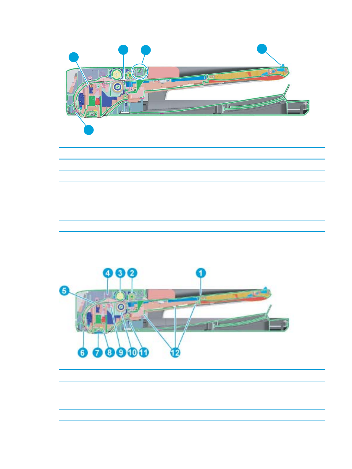
Figure 1-48 Document feeder sensors
1
2
5
3
4
Table 1-41 Document feeder sensors
Item Description
1 ADF Y (length) sensor
2 ADF paper present sensor
3 ADF deskew sensor
4 Paper path sensor 1
NOTE: For an e-duplex copy job, this sensor is used to activate the front-side scan module (in the
scanner base) and the front-side background selector (in the document feeder), if needed.
5 ADF jam cover sensor (open the jam access cover and insert a folded piece of paper to activate the ag)
Document feeder paper path
Figure 1-49 Document feeder paper path
Table
1-42 Document feeder paper path
Item Description Item Description
1 Input tray 7 Front-side scan module
NOTE: This scan module (document feeder glass) is
located in the scanner base.
2 Pre-pick roller 8 Back-side scan module
ENWW Document feeder system (M631, M632, M633) 71
Page 98

Table 1-42 Document feeder paper path (continued)
Item Description Item Description
3 Pick roller 9 ADF pick success transmitter
4 ADF pick success receiver 10 Separator roller
5 Deskew drive roller 11 Exit drive roller
6 Prescan drive roller 12 Lift plate
Document feeder simplex operation
Following is the basic sequence of operation for a document feeder simplex job.
1. The ADF jam cover sensor detects when the cover door is in the closed position.
2. The ADF paper present sensor activates when paper is loaded onto the input tray.
3. The feed motor rotates to raise the lift plate and starts to pick the loaded paper.
4. The ADF multi-pick (ultrasonic) sensor activates when the leading edge of the media is driven past the
sensor. The printer rmware registers a successful pick operation.
5. The ADF paper path deskew activates when the leading edge of the paper passes it. The printer rmware
registers the leading edge of the paper position.
6. The leading edge of the paper drives into the nip point of the deskew drive roller and the deskew pinch
rollers. This creates a buckle of paper by the nip point for pick-skew correction.
7. The deskew motor rotates the deskew drive roller to pull the paper into the prescan drive roller.
8. The pick motor stops turning and allows both the pick and feed roller to turn freely while the paper is
pulled in by the deskew drive roller.
9. The feed motor rotates to drive the paper into the prescan front-side sensor. The rmware registers the
leading edge position of the paper as the multi-pick sensor activates.
10. The feed motor continues to rotate and drive the leading edge of the paper through the preset distance
from the multi-pick sensor to the front-side scan zone. The scanner begins the scanning and data
retrieval process.
11. The ADF multi-pick (ultrasonic) sensor deactivates when the trailing edge of the paper passes the
sensor. The rmware registers the trailing edge of the paper position.
12. The feed motor continues to rotate and drive the trailing edge of the paper through the preset distance
from the ADF multi-pick (ultrasonic) sensor to the front-side scan zone. The scanner ends the scanning
and data retrieval process.
13. The feed motor continues to rotate and ejects the trailing edge of the paper into the output bin.
14. One of the following occurs:
●
If the copy job is complete, the ADF paper present sensor deactivates. The feed motor reverses
rotation to raise the pick roller.
●
If the copy job is not complete, the ADF paper present sensor is active. The printer rmware detects
additional pages in the input tray and the process repeats.
72 Chapter 1 Theory of operation ENWW
Page 99

Document feeder e-duplex operation
Following is the basic sequence of operation for a document feeder simplex job.
NOTE: For an e-duplex copy job, the background scan operation begins immediately after the simplex
sequence of operation ends.
1. The feed motor continues to drive the paper until the leading edge activates the prescan back-side
sensor. The printer rmware registers the position of the leading edge of the paper.
2. The feed motor continues to rotate to drive the leading edge of the paper through the preset distance
from prescan back-side sensor to the back-side background selector scan zone. The back-side
background scan module begins scanning and retrieval of the data.
3. The prescan back-side sensor deactivates when the trailing edge of the paper passes it. The printer
rmware registers the trailing edge of the paper position.
4. The feed motor continues to rotate to drive the trailing edge of the paper edge past the back-side
background selector scan zone.
5. The feed motor continues to rotate and ejects the trailing edge of the paper into the output bin.
6. One of the following occurs:
●
If the copy job is complete, the ADF paper present sensor deactivates. The feed motor reverses
rotation to raise the pick roller.
●
If the copy job is not complete, the ADF paper present sensor is active. The printer rmware detects
additional pages in the input tray and the process repeats.
ENWW Document feeder system (M631, M632, M633) 73
Page 100

Deskew operation
Sliding side guides on the input tray make sure that the paper stack is correctly aligned at the center of the
input tray when paper is loaded in the tray. The correct position of the loaded paper is parallel with the
direction of travel into the document feeder paper path.
The document feeder further reduces paper skew due to improper loading of paper in the input tray by
buckling the paper to create a paper buer.
The document feeder aligns the leading edge of the paper parallel with the deskew drive rollers before it is
driven further into the document feeder paper path.
NOTE: If the page to be copied is smaller than the minimal sliding guide setting, do not use the document
feeder for the copy job. Attempting to copy too small of a page using the document feeder can result in
document feeder jams and/or damage to the original page. Instead, use the atbed glass to copy the page.
Figure 1-50 Deskew operation
Document feeder hinges
The document feeder hinges allow positioning the assembly vertically above the scanner glass to
accommodate the placement of books and other objects up to 25 mm (1.0 in) in height on the scanner glass.
The document feeder still closes (the bottom of the ADF is kept parallel to the scanner glass) and allows the
printer to operate.
The document feeder hinges provide height adjustment of 25 mm (1.0 in) when a maximum downward force
of 4.5 kg (10 lb) is applied at the front edge of the assembly, with the fulcrum (such as the spine of a book)
centered on the scanner glass and parallel to its long axis.
The document feeder will withstand a downward force of about 4.5 kg (10 lb) applied at the front edge center
of the assembly—when the fulcrum (such as the spine of a book) is located anywhere on the scanner glass
and parallel to its long axis—without breaking, deforming, detaching or experiencing performance
degradation.
The document feeder hinges support the assembly in the open position and prevent the document feeder
from suddenly closing in a damaging or loud manner.
The hinges can hold the document feeder static in all positions higher than 100 mm (3.93 in); measured at the
front of the assembly. Less than 2.3 kg (5 lb) of force is required to open or close the document feeder.
74 Chapter 1 Theory of operation ENWW
 Loading...