

Page 1

Service Manual
M433a/M436n/M436dn M436nda
LaserJet MFP M433a, M436n, M436dn, M436nda
www.hp.com/support/ljM436MFP
www.hp.com/support/ljM433MFP
Page 2

Page 3

HP LaserJet MFP M433a, M436n, M436dn,
M436nda
Service Manual
Page 4

Copyright and License
Trademark Credits
© Copyright 2018 HP Development Company,
L.P.
Reproduction, adaptation, or translation without
prior written permission is prohibited, except as
allowed under the copyright laws.
The information contained herein is subject to
change without notice.
The only warranties for HP products and
services are set forth in the express warranty
statements accompanying such products and
services. Nothing herein should be construed as
constituting an additional warranty. HP shall not
be liable for technical or editorial errors or
omissions contained herein.
Edition 4, 4/2018
Adobe®, Acrobat®, and PostScript® are
tr
ademarks of Adobe Systems Incorporated.
Microsoft®, Windows®, Windows® XP, and
Windows Vista® are U.S. registered trademarks
of Microsoft Corporation.
Page 5

Conventions used in this guide
TIP: Tips provide helpful hints or shortcuts.
NOTE: Notes provide important information to explain a concept or to complete a task.
CAUTION: Cautions indicate procedures that you should follow to avoid losing data or damaging the product.
WARNING! Warnings alert you to specic procedures that you should follow to avoid personal injury,
catastrophic loss of data, or extensive damage to the product.
ENWW iii
Page 6

iv Conventions used in this guide ENWW
Page 7

Table of contents
1 Product specs and features .................................................................................................................................................................... 1
Product Overview ..................................................................................................................................................................... 2
Specications ............................................................................................................................................................................ 3
General Specications ......................................................................................................................................... 3
Print specications ............................................................................................................................................... 4
Controller and software specication ............................................................................................................... 4
Scan specication ................................................................................................................................................ 5
Copy specication ................................................................................................................................................ 7
Paper handling specication .............................................................................................................................. 7
Supplies ................................................................................................................................................................. 9
Maintenance parts ............................................................................................................................................... 9
Optional accessories ......................................................................................................................................... 10
System conguration ............................................................................................................................................................ 11
Feeding system ...................................................................................................................................................................... 14
Feeding system overview ................................................................................................................................ 14
Main components and functions ..................................................................................................................... 15
Cassette .............................................................................................................................................................. 17
Pickup roller and friction pad ........................................................................................................................... 18
Registration roller .............................................................................................................................................. 18
MPF(Multi-Purpose Feeder) unit ..................................................................................................................... 19
Image Creation ....................................................................................................................................................................... 21
Printing process overview ................................................................................................................................ 21
Imaging unit ........................................................................................................................................................ 21
Imaging unit overview .................................................................................................................. 21
Drum drive ..................................................................................................................................... 22
Developer unit ............................................................................................................................... 22
Fuser unit ................................................................................................................................................................................. 25
Fuser unit overview ........................................................................................................................................... 25
Fuser duplex exit drive ..................................................................................................................................... 26
Fuser unit temperature control ....................................................................................................................... 26
Laser Scanning unit (LSU) ..................................................................................................................................................... 28
LSU overview ...................................................................................................................................................... 28
ENWW v
Page 8

Laser scanning optical path ............................................................................................................................. 29
Laser synchronizing detectors ........................................................................................................................ 29
Drive system ........................................................................................................................................................................... 31
Drive motors ....................................................................................................................................................... 31
Main drive unit (OPC_DEVE_REGI_MP_pickup) ............................................................................................. 32
Fuser duplex exit drive ..................................................................................................................................... 34
Toner cartridge drive ......................................................................................................................................... 35
Scanner System ..................................................................................................................................................................... 36
Scanner system overview ................................................................................................................................ 36
Scanning system components ........................................................................................................................ 36
Document feeder ................................................................................................................................................................... 38
Document feeder overview ............................................................................................................................. 38
Electrical parts location .................................................................................................................................... 39
Document feeder drive system ....................................................................................................................... 39
Overview ......................................................................................................................................... 39
Document feeder original drive assembly ................................................................................ 40
Document feeder registration drive assembly ........................................................................ 41
Document feeder feed drive assembly ..................................................................................... 42
Document feeder exit drive assembly ...................................................................................... 42
Original return drive ...................................................................................................................... 43
Hardware conguration ........................................................................................................................................................ 44
Overview ............................................................................................................................................................. 44
Circuit Board Locations ..................................................................................................................................... 45
Formatter (Main) board .................................................................................................................................... 45
Formatter (Main) board .................................................................................................................................... 46
OPE board ........................................................................................................................................................... 47
SMPS (LVPS) board (HP LaserJet MFP M436n/M436dn Printer only) ....................................................... 49
SMPS (LVPS) board (HP LaserJet MFP M436nda Printer only) ................................................................... 50
HVPS board ......................................................................................................................................................... 52
BLU PBA (back light unit) .................................................................................................................................. 55
Document feeder board ................................................................................................................................... 55
Tray 3 accessory board .................................................................................................................................... 57
Sensor location .................................................................................................................................................. 57
2 Removal and replacement .................................................................................................................................................................... 61
For additional service and support ...................................................................................................................................... 63
Removal and replacement strategy ................................................................................................................................... 64
Electrostatic discharge ..................................................................................................................................... 64
Required tools .................................................................................................................................................... 65
Types of screws ................................................................................................................................................. 65
Service approach .................................................................................................................................................................... 65
vi ENWW
Page 9

Before performing service ............................................................................................................................... 65
Releasing Plastic Latches ................................................................................................................................. 65
After performing service .................................................................................................................................. 65
Post-service test ................................................................................................................................................ 66
Print-quality test ........................................................................................................................... 66
Removal: Toner cartridge ..................................................................................................................................................... 67
Introduction ........................................................................................................................................................ 67
Overview ......................................................................................................................................... 67
Before performing service .......................................................................................................... 67
Required tools ............................................................................................................................... 67
After performing service .............................................................................................................. 67
Post service test ............................................................................................................................ 68
Remove: Toner cartridge .................................................................................................................................. 68
Removal: Transfer roller ....................................................................................................................................................... 71
Introduction ........................................................................................................................................................ 71
Overview ......................................................................................................................................... 71
Before performing service .......................................................................................................... 71
Required tools ............................................................................................................................... 71
After performing service .............................................................................................................. 71
Post service test ............................................................................................................................ 71
Remove: Transfer roller .................................................................................................................................... 71
Removal: Fuser unit ............................................................................................................................................................... 74
Introduction ........................................................................................................................................................ 74
Overview ......................................................................................................................................... 74
Before performing service .......................................................................................................... 74
Required tools ............................................................................................................................... 74
After performing service .............................................................................................................. 74
Post service test ............................................................................................................................ 74
Remove: Fuser unit ........................................................................................................................................... 74
Removal: Imaging unit (drum unit and developer) ........................................................................................................... 77
Introduction ........................................................................................................................................................ 77
Overview ......................................................................................................................................... 77
Before performing service .......................................................................................................... 77
Required tools ............................................................................................................................... 77
After performing service .............................................................................................................. 77
Post service test ............................................................................................................................ 77
Remove: Imaging unit (drum unit and developer) ....................................................................................... 77
Removal: Pickup roller and friction pad .............................................................................................................................. 88
Introduction ........................................................................................................................................................ 88
Overview ......................................................................................................................................... 88
Before performing service .......................................................................................................... 88
ENWW vii
Page 10

Required tools ............................................................................................................................... 88
After performing service .............................................................................................................. 88
Post service test ............................................................................................................................ 88
Remove: Pickup roller and friction pad .......................................................................................................... 88
Removal: MP pickup roller and friction pad ....................................................................................................................... 91
Introduction ........................................................................................................................................................ 91
Overview ......................................................................................................................................... 91
Before performing service .......................................................................................................... 91
Required tools ............................................................................................................................... 91
After performing service .............................................................................................................. 91
Post service test ............................................................................................................................ 91
Remove: MP pickup roller and friction pad .................................................................................................... 91
Removal: Document feeder pickup roller assembly ........................................................................................................ 96
Introduction ........................................................................................................................................................ 96
Overview ......................................................................................................................................... 96
Before performing service .......................................................................................................... 96
Required tools ............................................................................................................................... 96
After performing service .............................................................................................................. 96
Post service test ............................................................................................................................ 96
Remove: Document feeder pickup roller assembly ..................................................................................... 96
Removal: Document feeder friction pad ............................................................................................................................ 98
Introduction ........................................................................................................................................................ 98
Overview ......................................................................................................................................... 98
Before performing service .......................................................................................................... 98
Required tools ............................................................................................................................... 98
After performing service .............................................................................................................. 98
Post service test ............................................................................................................................ 98
Remove: Document feeder friction pad ......................................................................................................... 98
Removal: Rear cover ........................................................................................................................................................... 100
Introduction ...................................................................................................................................................... 100
Overview ...................................................................................................................................... 100
Before performing service ........................................................................................................ 100
Required tools ............................................................................................................................. 100
After performing service ........................................................................................................... 100
Post service test ......................................................................................................................... 100
Remove: Rear cover ........................................................................................................................................ 100
Removal: Front cover .......................................................................................................................................................... 102
Introduction ...................................................................................................................................................... 102
Overview ...................................................................................................................................... 102
Before performing service ........................................................................................................ 102
Required tools ............................................................................................................................. 102
viii ENWW
Page 11

After performing service ........................................................................................................... 102
Post service test ......................................................................................................................... 102
Remove: Front cover ...................................................................................................................................... 102
Removal: Left cover ............................................................................................................................................................ 104
Introduction ...................................................................................................................................................... 104
Overview ...................................................................................................................................... 104
Before performing service ........................................................................................................ 104
Required tools ............................................................................................................................. 104
After performing service ........................................................................................................... 104
Post service test ......................................................................................................................... 104
Remove: Left cover ......................................................................................................................................... 104
Removal: Formatter board ................................................................................................................................................. 106
Introduction ...................................................................................................................................................... 106
Overview ...................................................................................................................................... 106
Before performing service ........................................................................................................ 106
Required tools ............................................................................................................................. 106
After performing service ........................................................................................................... 106
Post service test ......................................................................................................................... 106
Remove: Formatter board ............................................................................................................................. 106
Removal: LVPS board .......................................................................................................................................................... 108
Introduction ...................................................................................................................................................... 108
Overview ...................................................................................................................................... 108
Before performing service ........................................................................................................ 108
Required tools ............................................................................................................................. 108
After performing service ........................................................................................................... 108
Post service test ......................................................................................................................... 108
Remove: LVPS board ...................................................................................................................................... 108
Removal: Front cover open sensor ................................................................................................................................... 110
Introduction ...................................................................................................................................................... 110
Overview ...................................................................................................................................... 110
Before performing service ........................................................................................................ 110
Required tools ............................................................................................................................. 110
After performing service ........................................................................................................... 110
Post service test ......................................................................................................................... 110
Remove: Front cover open sensor ............................................................................................................... 110
Removal: Side unit ............................................................................................................................................................... 112
Introduction ...................................................................................................................................................... 112
Overview ...................................................................................................................................... 112
Before performing service ........................................................................................................ 112
Required tools ............................................................................................................................. 112
After performing service ........................................................................................................... 112
ENWW ix
Page 12

Post service test ......................................................................................................................... 112
Remove: Side unit ........................................................................................................................................... 112
Removal: Side cover-open sensor .................................................................................................................................... 114
Introduction ...................................................................................................................................................... 114
Overview ...................................................................................................................................... 114
Before performing service ........................................................................................................ 114
Required tools ............................................................................................................................. 114
After performing service ........................................................................................................... 114
Post service test ......................................................................................................................... 114
Remove: Side cover-open sensor ................................................................................................................. 114
Removal: Platen cover (M433a/M436n/M436dn only) ................................................................................................. 117
Introduction ...................................................................................................................................................... 117
Overview ...................................................................................................................................... 117
Before performing service ........................................................................................................ 117
Required tools ............................................................................................................................. 117
After performing service ........................................................................................................... 117
Post service test ......................................................................................................................... 117
Remove: Platen cover (M433a/M436n/M436dn only) ............................................................................. 117
Removal: Document feeder unit (optional) ..................................................................................................................... 119
Introduction ...................................................................................................................................................... 119
Overview ...................................................................................................................................... 119
Before performing service ........................................................................................................ 119
Required tools ............................................................................................................................. 119
After performing service ........................................................................................................... 119
Post service test ......................................................................................................................... 119
Remove: Document feeder unit (optional) ................................................................................................. 119
Removal: Document feeder cover .................................................................................................................................... 122
Introduction ...................................................................................................................................................... 122
Overview ...................................................................................................................................... 122
Before performing service ........................................................................................................ 122
Required tools ............................................................................................................................. 122
After performing service ........................................................................................................... 122
Post service test ......................................................................................................................... 122
Remove: Document feeder cover ................................................................................................................. 122
Removal: Document feeder open cover .......................................................................................................................... 125
Introduction ...................................................................................................................................................... 125
Overview ...................................................................................................................................... 125
Before performing service ........................................................................................................ 125
Required tools ............................................................................................................................. 125
After performing service ........................................................................................................... 125
Post service test ......................................................................................................................... 125
x ENWW
Page 13

Remove: Document feeder open cover ....................................................................................................... 125
Removal: Document feeder stacker ................................................................................................................................. 127
Introduction ...................................................................................................................................................... 127
Overview ...................................................................................................................................... 127
Before performing service ........................................................................................................ 127
Required tools ............................................................................................................................. 127
After performing service ........................................................................................................... 127
Post service test ......................................................................................................................... 127
Remove: Document feeder stacker ............................................................................................................. 127
Removal: Document feeder board ................................................................................................................................... 129
Introduction ...................................................................................................................................................... 129
Overview ...................................................................................................................................... 129
Before performing service ........................................................................................................ 129
Required tools ............................................................................................................................. 129
After performing service ........................................................................................................... 129
Post service test ......................................................................................................................... 129
Remove: Document feeder board ................................................................................................................ 129
Removal: Document feeder registration-cover-detect sensor .................................................................................... 131
Introduction ...................................................................................................................................................... 131
Overview ...................................................................................................................................... 131
Before performing service ........................................................................................................ 131
Required tools ............................................................................................................................. 131
After performing service ........................................................................................................... 131
Post service test ......................................................................................................................... 131
Remove: Document feeder registration-cover-detect sensor ................................................................ 131
Removal: Document feeder motor solenoid clutch ....................................................................................................... 133
Introduction ...................................................................................................................................................... 133
Overview ...................................................................................................................................... 133
Before performing service ........................................................................................................ 133
Required tools ............................................................................................................................. 133
After performing service ........................................................................................................... 133
Post service test ......................................................................................................................... 133
Remove: Document feeder motor solenoid clutch ................................................................................... 133
Removal: Document feeder exit idle sensor ................................................................................................................... 138
Introduction ...................................................................................................................................................... 138
Overview ...................................................................................................................................... 138
Before performing service ........................................................................................................ 138
Required tools ............................................................................................................................. 138
After performing service ........................................................................................................... 138
Post service test ......................................................................................................................... 138
Remove: Document feeder exit idle sensor ............................................................................................... 138
ENWW xi
Page 14

Removal: Document feeder exit sensor .......................................................................................................................... 140
Introduction ...................................................................................................................................................... 140
Overview ...................................................................................................................................... 140
Before performing service ........................................................................................................ 140
Required tools ............................................................................................................................. 140
After performing service ........................................................................................................... 140
Post service test ......................................................................................................................... 140
Remove: Document feeder exit sensor ....................................................................................................... 140
Removal: Document feeder length-width sensor .......................................................................................................... 142
Introduction ...................................................................................................................................................... 142
Overview ...................................................................................................................................... 142
Before performing service ........................................................................................................ 142
Required tools ............................................................................................................................. 142
After performing service ........................................................................................................... 142
Post service test ......................................................................................................................... 142
Remove: Document feeder length-width sensor ...................................................................................... 142
Removal: OPE unit ............................................................................................................................................................... 144
Introduction ...................................................................................................................................................... 144
Overview ...................................................................................................................................... 144
Before performing service ........................................................................................................ 144
Required tools ............................................................................................................................. 144
After performing service ........................................................................................................... 144
Post service test ......................................................................................................................... 144
Remove: OPE unit ........................................................................................................................................... 144
Removal: Platen unit ........................................................................................................................................................... 147
Introduction ...................................................................................................................................................... 147
Overview ...................................................................................................................................... 147
Before performing service ........................................................................................................ 147
Required tools ............................................................................................................................. 147
After performing service ........................................................................................................... 147
Post service test ......................................................................................................................... 147
Remove: Platen unit ....................................................................................................................................... 147
Removal: Upper platen ....................................................................................................................................................... 151
Introduction ...................................................................................................................................................... 151
Overview ...................................................................................................................................... 151
Before performing service ........................................................................................................ 151
Required tools ............................................................................................................................. 151
After performing service ........................................................................................................... 151
Post service test ......................................................................................................................... 151
Remove: Upper platen ................................................................................................................................... 151
Removal: CIS unit ................................................................................................................................................................. 154
xii ENWW
Page 15

Introduction ...................................................................................................................................................... 154
Overview ...................................................................................................................................... 154
Before performing service ........................................................................................................ 154
Required tools ............................................................................................................................. 154
After performing service ........................................................................................................... 154
Post service test ......................................................................................................................... 154
Remove: CIS unit ............................................................................................................................................. 154
Removal: Scan drive unit .................................................................................................................................................... 156
Introduction ...................................................................................................................................................... 156
Overview ...................................................................................................................................... 156
Before performing service ........................................................................................................ 156
Required tools ............................................................................................................................. 156
After performing service ........................................................................................................... 156
Post service test ......................................................................................................................... 156
Remove: Scan drive unit ................................................................................................................................ 156
Removal: Scan home-position sensor and cover-open sensor ................................................................................... 158
Introduction ...................................................................................................................................................... 158
Overview ...................................................................................................................................... 158
Before performing service ........................................................................................................ 158
Required tools ............................................................................................................................. 158
After performing service ........................................................................................................... 158
Post service test ......................................................................................................................... 158
Remove: Scan home-position sensor and cover-open sensor ............................................................... 158
Removal: Laser/scanner unit (LSU) ................................................................................................................................... 160
Introduction ...................................................................................................................................................... 160
Overview ...................................................................................................................................... 160
Before performing service ........................................................................................................ 160
Required tools ............................................................................................................................. 160
After performing service ........................................................................................................... 160
Post service test ......................................................................................................................... 160
Remove: Laser/scanner unit (LSU) ............................................................................................................... 160
Removal: Main drive motor ................................................................................................................................................ 162
Introduction ...................................................................................................................................................... 162
Overview ...................................................................................................................................... 162
Before performing service ........................................................................................................ 162
Required tools ............................................................................................................................. 162
After performing service ........................................................................................................... 162
Post service test ......................................................................................................................... 162
Remove: Main drive motor ............................................................................................................................ 162
Removal: Exit motor (MFP M436nda only) ...................................................................................................................... 164
Introduction ...................................................................................................................................................... 164
ENWW xiii
Page 16

Overview ...................................................................................................................................... 164
Before performing service ........................................................................................................ 164
Required tools ............................................................................................................................. 164
After performing service ........................................................................................................... 164
Post service test ......................................................................................................................... 164
Remove: Exit motor (MFP M436nda only) .................................................................................................. 164
Removal: Fuser motor ........................................................................................................................................................ 166
Introduction ...................................................................................................................................................... 166
Overview ...................................................................................................................................... 166
Before performing service ........................................................................................................ 166
Required tools ............................................................................................................................. 166
After performing service ........................................................................................................... 166
Post service test ......................................................................................................................... 166
Remove: Fuser motor ..................................................................................................................................... 166
Removal: Paper empty registration MP sensor .............................................................................................................. 168
Introduction ...................................................................................................................................................... 168
Overview ...................................................................................................................................... 168
Before performing service ........................................................................................................ 168
Required tools ............................................................................................................................. 168
After performing service ........................................................................................................... 168
Post service test ......................................................................................................................... 168
Remove: Paper empty registration MP sensor .......................................................................................... 168
Removal: MP clutch ............................................................................................................................................................. 172
Introduction ...................................................................................................................................................... 172
Overview ...................................................................................................................................... 172
Before performing service ........................................................................................................ 172
Required tools ............................................................................................................................. 172
After performing service ........................................................................................................... 172
Post service test ......................................................................................................................... 172
Remove: MP clutch ......................................................................................................................................... 172
Removal: Registration clutch ............................................................................................................................................. 174
Introduction ...................................................................................................................................................... 174
Overview ...................................................................................................................................... 174
Before performing service ........................................................................................................ 174
Required tools ............................................................................................................................. 174
After performing service ........................................................................................................... 174
Post service test ......................................................................................................................... 174
Remove: Registration clutch ......................................................................................................................... 174
Removal: Fuser fan .............................................................................................................................................................. 177
Introduction ...................................................................................................................................................... 177
Overview ...................................................................................................................................... 177
xiv ENWW
Page 17

Before performing service ........................................................................................................ 177
Required tools ............................................................................................................................. 177
After performing service ........................................................................................................... 177
Post service test ......................................................................................................................... 177
Remove: Fuser fan .......................................................................................................................................... 177
Removal: HVPS board ......................................................................................................................................................... 179
Introduction ...................................................................................................................................................... 179
Overview ...................................................................................................................................... 179
Before performing service ........................................................................................................ 179
Required tools ............................................................................................................................. 179
After performing service ........................................................................................................... 179
Post service test ......................................................................................................................... 179
Remove: HVPS board ..................................................................................................................................... 179
Removal: Temperature humidity sensor ......................................................................................................................... 181
Introduction ...................................................................................................................................................... 181
Overview ...................................................................................................................................... 181
Before performing service ........................................................................................................ 181
Required tools ............................................................................................................................. 181
After performing service ........................................................................................................... 181
Post service test ......................................................................................................................... 181
Remove: Temperature humidity sensor ..................................................................................................... 181
Removal: Developer unit .................................................................................................................................................... 184
Introduction ...................................................................................................................................................... 184
Overview ...................................................................................................................................... 184
Before performing service ........................................................................................................ 184
Required tools ............................................................................................................................. 184
After performing service ........................................................................................................... 184
Post service test ......................................................................................................................... 184
Remove: Developer unit ................................................................................................................................. 184
Removal: SCF (optional Tray 3) ......................................................................................................................................... 194
Introduction ...................................................................................................................................................... 194
Overview ...................................................................................................................................... 194
Before performing service ........................................................................................................ 194
Required tools ............................................................................................................................. 194
After performing service ........................................................................................................... 194
Post service test ......................................................................................................................... 194
Remove: SCF board ......................................................................................................................................... 195
Remove: SCF drive unit .................................................................................................................................. 196
Remove: SCF feed roller ................................................................................................................................. 198
ENWW xv
Page 18

3 Troubleshooting ................................................................................................................................................................................... 199
Control panel ........................................................................................................................................................................ 200
Understanding the status LED ........................................................................................................................................... 201
Clearing jams ........................................................................................................................................................................ 203
Introduction ...................................................................................................................................................... 203
Tray 2 ................................................................................................................................................................ 203
In optional Tray 3 ............................................................................................................................................ 205
In Multi-purpose Tray 1 .................................................................................................................................. 208
Inside the printer ............................................................................................................................................. 209
In the exit area ................................................................................................................................................. 211
In the duplex unit area ................................................................................................................................... 213
Clearing original document jams .................................................................................................................. 215
Original paper jam in front of scanner .................................................................................... 215
Original paper jam inside of scanner ....................................................................................... 217
Original paper jam in exit area of scanner .............................................................................. 220
Original paper jam in scanner duplex path ............................................................................. 222
Firmware upgrades ............................................................................................................................................................. 224
Determine the installed revision of rmware ............................................................................................. 225
Perform a rmware upgrade ........................................................................................................................ 226
HP Embedded Web Server ........................................................................................................ 226
USB Firmware Upgrade ............................................................................................................. 226
Tech Mode ............................................................................................................................................................................. 227
Overview ........................................................................................................................................................... 227
Entering Tech mode ....................................................................................................................................... 227
Tech mode menu ............................................................................................................................................ 227
Tech Mode Menu description ........................................................................................................................ 229
Control Panel Error Messages ........................................................................................................................................... 238
11-2T11, Paper mismatch Tray 2 Load [A4] [Plain] Continue ⊙ Cancel X ............................................ 238
11-2T21, Paper mismatch Tray 3 Load [A4] [Plain] Continue ⊙ Cancel X ............................................ 238
11-2T61, Paper mismatch Tray 1Load [A4] [Plain] Continue ⊙ Cancel X ............................................. 238
A1-1110, Error: #A1-1110 / Motor Failure: #A1-1110. Turn o then on. Call for service if the
problem persists ............................................................................................................................................. 238
A1–5513, Error: #A1–5513 / Motor Failure: #A1-1110. Turn o then on. Call for service if the
problem persists ............................................................................................................................................. 239
A2-1210, Error: #A2-1210 / Fan Failure: #A2-1210. Turn o then on. Call for service if the
problem persists ............................................................................................................................................. 241
A2-2110, Error: #A2-2110 / Fan Failure: #A2-2110. Turn o then on. Call for service if the
problem persists ............................................................................................................................................. 241
A3-3311, A3-3312, A3-3320, A3-3411, A3-3412 Sensor errors .......................................................... 242
C1-1110, C1-111A Toner errors ................................................................................................................... 243
C1-1140, C1-1160, C1-1170 Toner errors ................................................................................................. 244
xvi ENWW
Page 19

C1-1313, C1-1314 Errors .............................................................................................................................. 245
C1-1411 Toner Not Installed / Toner cartridge is not installed. Install it ............................................... 247
C1-1512, Toner Not Compatible / Toner cartridge is not compatible. Check guide ............................. 247
C1-1711, C1-1712 Errors .............................................................................................................................. 248
C3-1110, Prepare IMG. Unit / Prepare new imaging unit ......................................................................... 248
C3-1140, C3-1150, C3-1170 Imaging unit errors ..................................................................................... 249
C3-1312, C3-1411, C3-1414 Imaging unit errors ..................................................................................... 249
C3-1512, IMG. Not compatible / Imaging unit is not compatible. Check guide ..................................... 250
C3-1711, C3-1712 Imaging unit errors ...................................................................................................... 251
C9-2110, C9-2120, Prepare TR. Roller / Prepare with new transfer roller ........................................... 252
C9-2220, Error: #C9-2220 / TR Failure: #C9-2220. Install TR roller again ........................................... 252
H1-1210, Paper jam in tray 2 ....................................................................................................................... 254
H1-1220 Tray 2 door is open. Close it ......................................................................................................... 254
H1-1230, Error: #H1-1230 / Input System Failure: #H1-1230. Check tray 3 connection .................. 255
H1-1252, H1-1254, Paper empty in tray 2 / Paper is empty in tray 3. Load paper ............................ 255
M1-1110, Paper jam in tray 1 ....................................................................................................................... 255
M1-1610, Paper jam in tray 1 ....................................................................................................................... 256
M1-5112, M1-5113, Paper empty in tray 1 / Paper is empty in tray 1. Load paper ........................... 257
M1-5120, All Trays Empty / Paper is empty in all trays. Load paper ..................................................... 258
M1-5610, Paper Normal in Tray 1 ................................................................................................................ 258
M1-5612, Paper empty in Tray 1. Load paper ........................................................................................... 259
M2-1110, M2-2210 Jam inside errors ........................................................................................................ 259
M3-1110, Jam in exit area ............................................................................................................................. 261
S2-331D, Waiting for low temp / Waiting delay time for lower xing temperature… ......................... 262
S2-3321, Supplying Toner / Supplying and mixing toner to developer unit. Please wait… ................ 262
S2-3421, Calibrating density / Calibrating image density. Please wait… .............................................. 262
S2-4210, Front door is open. Close it .......................................................................................................... 263
S2-4410, Right door is open. Close it .......................................................................................................... 263
S3-3122, Scanner Locked / Scanner is locked. Press Stop button ......................................................... 263
S6-3123, IP Conict / This IP address conicts with that of other system ........................................... 264
U1-2132, U1-2315, U1-2320, U1-2330, U1-2334, U1-2340, U1-234H Fuser unit failure errors .. 265
U2-1111, U2-1112, U2-1113, U2-1114 LSU failure errors .................................................................... 266
U3-3211, U3-3213, U3-3214, U3-3311, U3-3313, U3-3314 Original paper jam / Original
paper jam inside of scanner. Remove jam .................................................................................................. 267
U3-3411, U3-3413, U3-3414 Original paper jam / Original paper jam inside of scanner.
Remove jam ..................................................................................................................................................... 269
U3-3511, U3-3513, U3-3514 Original paper jam / Original paper jam inside of scanner.
Remove jam ..................................................................................................................................................... 270
U3-3711, U3-3713, U3-3714 Original paper jam / Original paper jam inside of scanner.
Remove jam ..................................................................................................................................................... 271
U3-4210 Scanner door open / Top door of scanner is open. Close the door ....................................... 272
ENWW xvii
Page 20

Printing quality problems ................................................................................................................................................... 273
Adjusting the document feeder skew .............................................................................................................................. 278
Other errors .......................................................................................................................................................................... 280
System diagram ................................................................................................................................................................... 281
Glossary ..................................................................................................................................................................................................... 283
Index ........................................................................................................................................................................................................... 289
xviii ENWW
Page 21

1 Product specs and features
This chapter presents an overview of the major components of the printer, and it includes a detailed discussion
of the image-formation system.
ENWW 1
Page 22
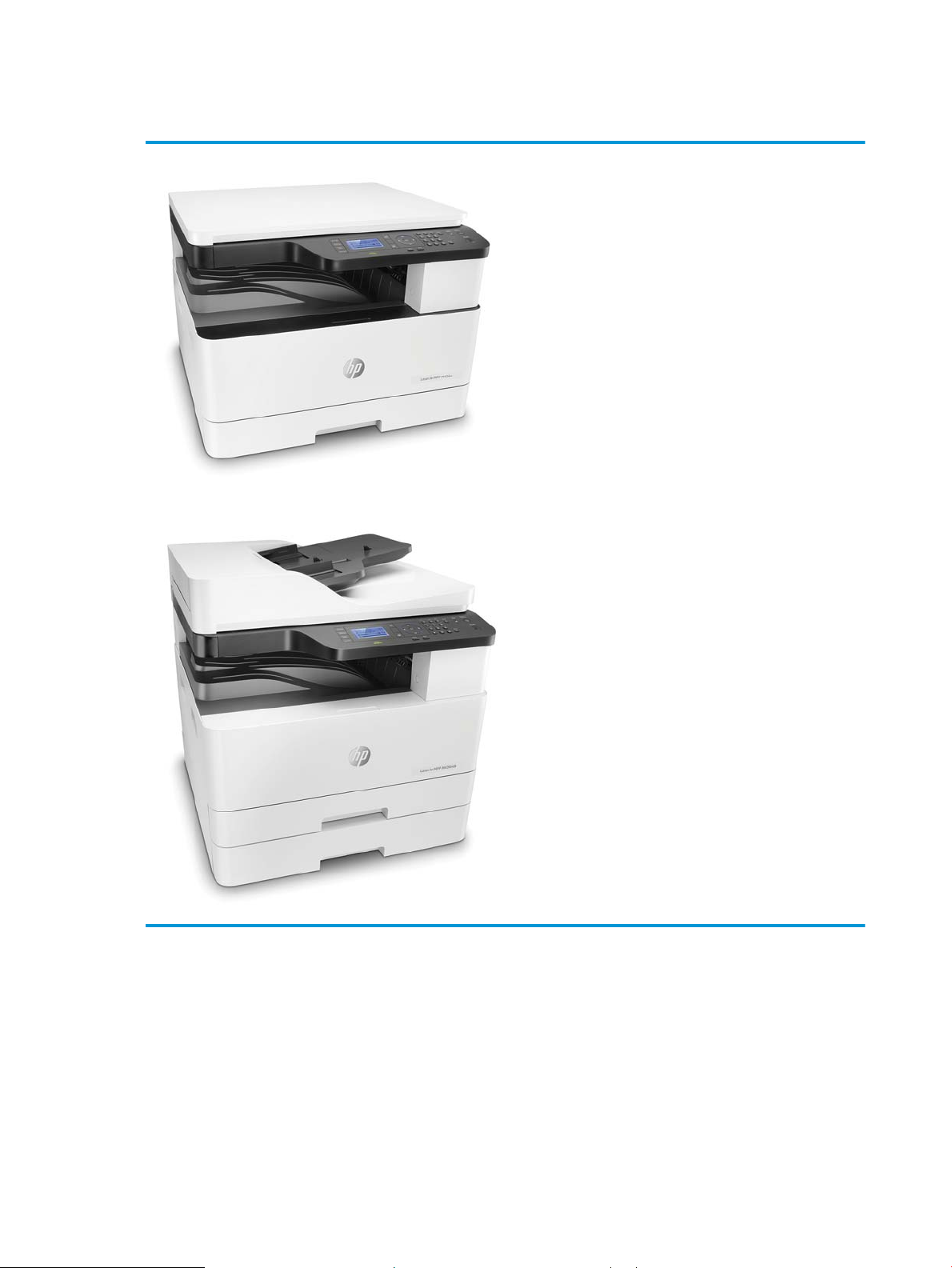
Product Overview
● Printing speed
– Up to 20 ppm on A4 or Letter M433
– Up to 23 ppm on A4 or Letter M436
● Scan speed (ADF)
– 30 ipm @ color 200dpi, 30 ipm @ mono 300dpi
● Processor
– 600 MHz
● Memory
– 128 MB
● Option unit
– Document feeder (M436n/dn only)
2 Chapter 1 Product specs and features ENWW
Page 23

Specications
Product specications are subject to change without notice.
General Specications
Table 1-1 General specications
Item Specication
Function ● HP LaserJet MFP M433a Printer: Print,
Temperature Operating 10 ~ 30 °C (50 ~ 86°F)
Humidity Operating 20~80% RH
Copy, Scan
● HP LaserJet MFP M436dn Printer:
Print, Copy, Scan, Network, Duplex
● HP LaserJet MFP M436n Printer: Print,
Copy, Scan
● HP LaserJet MFP M436nda Printer:
Print, Copy, Scan, Network, Duplex
Storage -10 ~ 40 °C (-4 ~ 104 °F)
Storage 10~90% RH
Acoustic Noise Level (Sound Power/
Pressure)
Power Supply Input Voltage AC 220-240V (-10%~6%)/5A
Power Consumption Ready 70 Wh
Dimension (W x L x H) M436n/M436dn models 560 x 540 x 417 mm (22.05 x 21.26 x
Printing ● Tray 2: 49 dBA
● Tray 3: 51 dBA
● MP Tray 1: 51 dBA
Copying ● Tray 2: 49dBA (@platen), 53dBA
(@document feeder)
● Tray 3: 51dBA(@platen), 55dBA
(@document feeder)
● MP Tray 1: 51dBA(@platen), 55dBA
(@document feeder)
Rated Frequency 50 Hz
Printing 500 Wh
Copying 500 Wh
Scanning 70 Wh
Power O 0.3 W
16.42 inches)
M436nda models 560 x 583.5 x 504.5 mm (22.5 x 22.97 x
19.86 inches)
Weight M436n/M436dn models 25 kg (55.12 lbs)
ENWW Specications 3
Page 24

Table 1-1 General specications (continued)
Item Specication
Reliability & Service Recommended Printing Volume (AMPV) 2,500 sheets/month
Print specications
Table 1-2 Print specications
Item Specication
Engine Speed Simplex Up to 23 ppm on A4 and Letter
FPOT From Ready Less than 9.2 sec
Resolution Optical 600 x 600 x 2 bit dpi
Printer Language PCL6
M436nda models M436nda models: 30.00 kg (66.14 lbs)
Max. Monthly Print Volume 50,000 sheets/month
Duplex Up to 10 ipm in A4 (10 ipm in Letter)
From Sleep Less than 22.2 sec
Enhanced 1200 x 1200 dpi
Controller and software specication
Table
1-3 Controller and software specication
Item Specication
Processor 600 MHz
Memory 128 MB
Memory Expansion N/A
Storage N/A
Printer driver Supporting OS [Windows]
● Windows 2000/XP(32/64bit)/
2003(32/64bit)/Vista(32/64bit)/2008/
Win7/2008 R2(64 only)/Windows 8/
Windows 8.1/Window Server 2012/
Windows 10 UPD
Default Driver PCL6
Driver feature [Windows]
● Watermark, Overlay, N-up printing,
Poster printing
● Manual duplex and auto duplex
(depending on model)
4 Chapter 1 Product specs and features ENWW
Page 25

Table 1-3 Controller and software specication (continued)
Item Specication
WHQL (Windows Hardware Quality Labs) Windows 2000/XP(32/64bit)/
Scan driver TWAIN Yes
WIA Yes
Supporting OS [Windows]
Table 1-4 Interface
Item Specication
Parallel (IEEE 1284) No
USB High-Speed USB 2.0
Wired LAN Ethernet 10/100 Base TX (M436 only)
Wireless LAN No
2003(32/64bit)/Vista(32/64bit)/2008/
Win7/2008 R2(64 only)/Windows 8/
Windows 8.1/Window Server 2012
● Windows 2000/XP(32/64bit)/
2003(32/64bit)/Vista(32/64bit)/2008/
Win7/2008 R2(64 only)/Windows 8/
Windows 8.1/Window Server 2012/
Windows 10
Table 1-5 Network Interface
Item Specication
Network Protocols TCP/IP Raw TCP/IP Printing, LPR/LPD, IPP, WSD,
IP Addressing Static IP Yes
Scan specication
1-6 Scan specication
Table
Item Specication
Scan method D-CIS
T4NET, SETIP
IPX/SPX No
Ether Talk No
NetBIOS over TCP/IP No
Auto IP Yes
BOOTP Yes
DHCP Yes
ENWW Specications 5
Page 26

Table 1-6 Scan specication (continued)
Item Specication
Compatibility TWAIN, WIA
Color Mode Mono/Gray/Color
Scan Speed B/W 30 ipm @ A4 and Letter
Gray 30 ipm @ A4 and Letter
Color 30 ipm @ A4 and Letter
Resolution Optical ● Platen: 600 x 600 dpi
● Document feeder: 300 x 300 dpi
(HP LaserJet MFP M436nda standard,
HP LaserJet MFP M436n/M436dn
optional)
Scan Size Document feeder (HP LaserJet MFP
M436nda standard, HP LaserJet MFP
M436n/M436dn optional)
platen ● Max. Document Width: Max. 297 mm
Scan-to PC (Local, Network) Yes
HDD No
USB No
Email No
Client No
SMB No
FTP No
● Max. Document Width: Max. 297 mm
● Max. Document Width: Max. 297 mm •
● Max. Document Length: Max. 432 mm
● Eective Scan Length: Max 424 mm
● Max. Document Width: Max. 297 mm •
● Max. Document Length: Max. 432 mm
● Eective Scan Length: Max 424 mm
Eective Scan Width: Max. 291 mm
Eective Scan Width: Max. 291 mm
HTTP(S) No
WebDAV No
Multi Destination No
Scan File Format PDF, Single-Page-TIFF, JPEG, Multi-Page-
TIFF, Single-Page-PDF, TIFF, Editable PDF
for Win7/8/8.1/10 on USB connect using the
HP Scan application
6 Chapter 1 Product specs and features ENWW
Page 27

Copy specication
Table 1-7 Copy specication
Item Specication
Copy Speed Up to 20 cpm in A4 & Letter
FCOT From Ready Less than 7.4 seconds (from platen)
Copy Original Type Text ● Platen: Scan 600 x 600 , Printing 600 x
From Sleep Less than 22.2 seconds (from platen)
From Coldboot Less than 22.2 seconds (from platen)
600
● Document feeder: Scan 600 x 600 ,
Printing 600 x 600
Text/Photo ● Platen: Scan 600 x 600 , Printing 600 x
600
● Document feeder: Scan 600 x 600 ,
Printing 600 x 600
Photo ● Platen: Scan 600 x 600 , Printing 600 x
600
● Document feeder: Scan 600 x 600 ,
Printing 600 x 600
Max. Original Size Platen 297 x 432 mm (11.7" x 17")
Copy Feature Multi Copy 1-+999
Paper handling specication
1-8 Paper handling specication
Table
Item Specication
Standard Capacity ● 250-sheet cassette Tray (20 lb or 80
Map ● Platen: Scan 600 x 600 , Printing 600 x
600
● Document feeder: Scan 600 x 600 ,
Printing 600 x 600
Document feeder 297 x 432 mm (11.7" x 17")
Reduce/Enlarge 25~400%
ID Card Copy Yes
N-up 2/4/8/16-up (A5), 2/4/8-up (A4), 2/4–up
(A3)
Collation Copy Yes (NDA only)
g/m²)
● 100-sheet MP tray (20 lb or 80 g/m²)
ENWW Specications 7
Page 28

Table 1-8 Paper handling specication (continued)
Item Specication
Max. Input Capacity ● HP LaserJet MFP M436nda Printer:
Printing Max. Size 297 x 432 mm (11.7" x 17")
Min. Size–Tray 1 125 x 101.6 mm (4.92 x 4 inches)
Min. Size–Tray 2/3 148.5 x 182 mm (5.83 x 7.17 inches)
Margin(T/B/L/R) 4.2+/-1.5mm
MP Tray Capacity ● Plain Paper: 100 sheets @ 80 g/m²
Media sizes A4,A5, B5 (JIS), Letter, Executive,
Media type Plain, HP LaserJet 90g, Light 60-74g,
Media weight ● 16 ~ 43 lb (60 to 163 g/m²): Simplex
600 sheets @ 20 lb or 80 g/m² (Tray 2
+ Optional Tray + Tray 1)
● HP LaserJet MFP M436n/M436dn
Printer: 350 sheets @ 20 lb or 80
g/m² (Tray 2 + Tray 1)
Statement, A3, B4 (JIS), 8K, 16K, Ledger,
Legal, Ocio 8.5 x 13, Ocio 216 x 1340, 4x6
Intermediate 85-95 g, Bond, Recycled, MidWeight 96-110g, Heavy 111-130g
Preprinted, Letterhead, Prepunched,
Cardstock, Colored
● 16 ~ 28 lb (60 to 110 g/m²): Duplex
Sensing Paper Empty Detect: Yes
Standard Cassette Tray Capacity 250 sheets @ 20 lb (80g/m²)
Media sizes A3/A4/A5/B4 (JIS)/B5 (JIS)/Ledger/Legal/
Ocio/Letter/Executive/4x6/8K/16K
Media types Plain, Mid-weight, Light, HP LaserJet,
Colored, Preprinted, Recycled, Intermediate,
Letterhead, Prepunched
Media weight ● 16 - 29 lb
● 60 - 110 gsm
Sensing Paper Empty: Yes
Optional Cassette Tray (M436 only) Capacity 250 sheets @ 20 lb (80g/m²)
Media sizes A3/A4/A5/B4 (JIS)/B5 (JIS)/Ledger/Legal/
Ocio 8.5 x 13, Ocio 216 x 340 mm/Letter/
Executive/8K/16K
Media types Plain, Mid-weight, Light, HP LaserJet,
Colored, Preprinted, Recycled, Intermediate,
Letterhead, Prepunched
Media weight ● 16 - 29 lb
● 60 - 110 gsm
Sensing Paper Empty: Yes
8 Chapter 1 Product specs and features ENWW
Page 29

Supplies
Table 1-8 Paper handling specication (continued)
Item Specication
Document feeder Capacity 100 sheets (20lb, 80 g/m²)
2-sided document scanning No
Document size ● Width: 128–297 mm
● Length:128–432 mm
Document weight ● 60~128g/m² (16-34lbs)
Sensing Paper Empty, Paper Width, Paper Length
When supplies reach the end of their life span, you can order the followings of supplies for your machine:
Item Description Part number
Toner Cartridge Standard-capacity replacement black toner
Imaging unit
1
The imaging unit must be installed by a service technician.
1
WARNING! When purchasing new toner cartridges or other supplies, these must be purchased in the same
country/region as the machine you are using. Otherwise, new toner cartridges or other supplies will be
incompatible with your machine due to dierent congurations of toner cartridges and other supplies according
to the specic country/region conditions.
CAUTION: HP does not recommend using non-genuine HP toner cartridge such as relled or remanufactured
toner. HP cannot guarantee non-genuine HP toner cartridge's quality. Service or repair required as a result of
using non-genuine HP toner cartridges will not be covered under the machine’s warranty.
NOTE: Depending on the options, percentage of image area and job mode used, the toner cartridge’s life span
may dier.
Maintenance parts
Table
1-9 Maintenance parts
CF256A
cartridge
High-capacity replacement black toner
cartridge
Replacement imaging drum CF257A
CF256X
Item Kit number Life
Pick-up roller and friction pad W7U01-67903 Approx. 100,000 pages
MP Pick-up roller and 50k friction pad (for
MP Tray)
Transfer roller W7U01-67901 Approx. 100,000 pages
Fuser unit W7U01-67902 Approx. 100,000 pages
ENWW Specications 9
Page 30

Table 1-9 Maintenance parts (continued)
Item Kit number Life
Document feeder Pick-Up roller assembly
(optional)
Document feeder Friction Pad (optional) W7U02-67902 Approx. 50,000 pages
NOTE: It will be aected by the operating system used, computing performance, application software,
connecting method, media, and media size and job complexity.
Optional accessories
You can purchase and install accessories to enhance your machine’s performance and capacity.
NOTE: Some features and optional goods may not be available depending on model or country/region.
Table 1-10 Option accessories
Accessory Function Part name
Optional tray
Document feeder
a
M436n/M436dn Only
b
Plain paper 80 g/m2 (20 lbs bond)
a
W7U02-67901 Approx. 120,000 pages
b
If you are experiencing frequent paper supply problems, you can attach an additional 250
sheet tray.
Automatic document feeder X0R65A
X0R64A
10 Chapter 1 Product specs and features ENWW
Page 31

System conguration
1
15
16
2 3
5
6
4
7
8
12
9
10
11
17
14
13
Figure 1-1 Front View
1 Automatic document feeder cover
2 Automatic document feeder width guide
3 Automatic document feeder input tray
4 Automatic document feeder output tray
5 Control panel
6 Multi-purpose tray
7 Tray 3 jam cover
8 Second Cassette Feeder (Tray 3) (optional)
9 Tray 2
10 Front cover
11 Output tray
12 Automatic document feeder
13 Scanner lid
14 Scanner glass
15 Imaging unit
ENWW System conguration 11
Page 32

16 Toner cartridge
3
1
2
17 Paper width guides on a multipurpose tray
NOTE: HP LaserJet MFP M436n/M436dn Printer models are equipped with a platen cover.
Figure 1-2 Rear view
1 Power receptacle
2 USB port
3 Network port
12 Chapter 1 Product specs and features ENWW
Page 33

Figure 1-3 System layout
1 Document feeder 11 Duplex 2 roller
2 Face down output tray 12 Transfer roller
3 Laser scanning unit 13 Fuser unit
4 Toner cartridge 14 Duplex 1 roller
5 Imaging unit 15 Exit-face down roller
6 Tray 2 16 Platen unit (Scanner)
7 SCF (optional Tray 3) 17 Document output tray
8 Registration frame idle roller 18 Document input tray
9 Registration-idle roller
10 Feed-registration roller
ENWW System conguration 13
Page 34

Feeding system
Registration Roller
Feeding system overview
The feeding system picks up paper from the cassette or MP tray and transports it to the printer inside. It consists
of the pickup roller, registration roller, transfer roller, MP pickup roller, exit unit, and side unit.
14 Chapter 1 Product specs and features ENWW
Page 35

Main components and functions
T ray 1
B ypa ss T ray
(MP T ray)
T ray 2
Main F rame
S CF (Opt.)
MP
E xit s ens or
E mpty s en sor
E mpty s ens or
S CF Feed sens or
E mpty s en sor
P /U R oller
P /U R oller
P /U R oller
S CF Feed R oller
E xit R o ller
Duplex R oller 1
Duplex R oller 2
OP C
T ran sfer
R oller
S IDE
Main Mo tor
E xit M otor
S CF Motor
S ide C ov er Inter Lo ck S wi tch
S CF Co ver I nter L ock Sw itch
Fus er
Fuer M otor
R egi s ens or
Regi
Roller
S CF
Regi
Roller
Figure 1-4 Sensor, Clutch, Motor
Table 1-11 Sensor, Clutch, Motor
Item Function
Side Interlock Switch Detects that the side cover is open.
Front cover Interlock Switch Detects that the front cover is open.
SCF Interlock Switch Detects that the SCF cover is open.
Multipurpose Tray 1(Main CST) Empty Sensor Detects that Multipurpose Tray1 is empty.
Tray 2(SCF CST) Empty Sensor Detects that tray2 is empty.
Multipurpose Empty Sensor Detects that Multipurpose Tray 1 is empty.
SCF Feed Sensor Detects the jam on SCF path.
Registration Sensor Detects the jam on regi path.
Exit Sensor Detects the jam on exit path.
SCF Motor Controls the SCF operation.
MP Pickup Clutch Controls the MP pickup roller operation.
Exit Motor Controls the exit roller operation.
ENWW Feeding system 15
Page 36

Table 1-11 Sensor, Clutch, Motor (continued)
1
2
4
5
6
7
8
9
10
11
12
13
3
14
15
16
Item Function
Multipurpose Tray 1 Pickup Clutch Controls the Multipurpose Tray 1 pickup roller operation.
Tray 2 Pickup Clutch Controls the Tray 2 (SCF) pickup roller operation.
Registration Clutch Controls the registration roller operation.
Figure 1-5 Rollers and friction pad
Table 1-12 Rollers and friction pad
Item Function
1 Tray 2 paper tray
2 Tray 3 Paper tray (optional)
3 Multipurpose Tray 1
4 Tray 2 Pickup Roller
5 Tray 2 Pickup Roller
6 Multipurpose Tray 1 pickup roller
7 Tray 3 feed Roller (Option)
8 Registration Sensor
16 Chapter 1 Product specs and features ENWW
Page 37

Cassette
Table 1-12 Rollers and friction pad (continued)
Item Function
9 Registration Roller
10 Transfer Roller
11 Exit Roller
12 Duplex Roller 1
13 Duplex Roller 2
14 Tray 2 Friction Pad
15 Tray 3 Friction Pad (Option)
16 Multipurpose Tray 1 Friction Pad
The cassette stores paper. Paper size in the cassette is set using the front/rear guide.
Figure 1-6 Cassette
Table 1-13 Cassette
Item Description
1 Structure: Cassette type
2 Capacity: 250 sheets ( 80g/m² paper standard)
3 Support paper
See Paper handling specication for more information
4 Paper type and weight
See Paper handling specication for more information
5 Plate knock up lift type: Spring (2ea)
ENWW Feeding system 17
Page 38

Pickup roller and friction pad
When the cassette is installed, the LOCKER-CASSETTE is released and risen by the pressure spring of the PLATEKNOCK UP. The surface of the paper contacts the pickup roller and a single sheet of paper is fed by the pickup
roller rotation. After rst page feeding, paper is separated and moved by the friction pad.
Figure 1-7 Pickup roller and friction pad
Registration roller
The registration roller is driven by the main motor. The registration roller clutch is located between the main
motor and registration roller, and it controls ON/OFF of the registration roller in order to match paper and an
image on the drum at the predetermined registration point.
18 Chapter 1 Product specs and features ENWW
Page 39

Specication
Figure 1-8 Registration roller
● Skew in simplex
– Top skew: 1.5 mm (MP 1.8 mm)
– Side skew: 2.2 mm
● Margin
– Top margin: 4.23 ± 1.5 mm
– Side margin: 4.23 ± 2.0 mm
– Duplex top margin: 4.23 ± 1.8 mm
– Duplex side margin: 4.23 ± 2.6 mm
MPF(Multi-Purpose Feeder) unit
The MPF unit allows feeding of special media cardstock, and custom size paper.
ENWW Feeding system 19
Page 40

Specication
Figure 1-9 MPF(Multi-Purpose Feeder) unit
● Capacity: 100 sheets ( 80g/m² paper standard)
● Media size: max 11.7” × 17” (297×432 mm)/Min 6”×4” (152.4×101.6mm)
● Media weight: Plain paper 60 ~ 163 g/m²
● Feeding speed: 20 ppm Letter/A4 LEF (Long Edge Feeding)
20 Chapter 1 Product specs and features ENWW
Page 41

Image Creation
Printing process overview
This printer uses one imaging unit and one laser beam for mono printing. Imaging unit consists of a drum unit
and developer unit.
The drum unit consists of an OPC drum, charge roller, and cleaning blade.
Figure 1-10 Printing process overview
1. OPC drum charge: The charge roller gives the drum a negative charge.
2. Laser exposure: Light produced by a laser diode hits the charged OPC through the lens and mirrors.
3. Development: The magnetic roller carries negatively-charged toner to the latent image on the drum
surface.
4. Transfer: The transfer roller opposite the OPC drum transfers toner from the drum to the paper.
5. Cleaning for OPC drum: The cleaning blade removes remaining toner on the drum surface after image
transfer to the paper.
6. Quenching for OPC drum: Discharge cleaning is done by illuminating the whole area of the drum with the
cleaning lamp at the end of every job.
Imaging unit
Imaging unit overview
The Imaging unit consists of the drum unit and the developer unit.
The diameter of the drum is 30 mm (circumference: about 94.2 mm).
The developing gap between the OPC drum and the magnetic roller cannot be adjusted. The ID chip is the sub
part of the drum unit. It stores the printed page-count information and data.
ENWW Image Creation 21
Page 42

Drum drive
Figure 1-11 Imaging unit overview
The OPC drum and magnetic roller are driven by one BLDC motor and supplied with power from the coupling.
The drive shaft is directly inserted into the OPC drum to x the drum unit. This structure provides stable printing
quality.
Figure 1-12 Drum drive
Developer unit
This printer uses a dual-component development system.
The developer unit contains 255g of toner carrier that is supplied to the magnetic roller (callout A) by the two
mixing augers (callout B). The diameter of the magnetic roller is 18.2 mm.
22 Chapter 1 Product specs and features ENWW
Page 43

The developer unit has a TC (toner concentration) sensor (callout C). It is used for controlling the operating range
of toner density.
Figure 1-13 Developer unit
Developer Circulation
Two mixing augers (callout A) circulate the developer forward and backward to agitate the developer in order to
mix the developer and toner well.
This occurs at the following times:
● During the process control self-checking
● During toner supply job
● During development job
The developer unit must be stored below 50 degrees C or the toner will harden and not work properly.
ENWW Image Creation 23
Page 44

Figure 1-14 Developer Circulation
24 Chapter 1 Product specs and features ENWW
Page 45

Fuser unit
Fuser unit overview
This unit fuses the toner that was transferred by the transfer roller onto the paper, by applying heat and
pressure. This printer's two-roller fusing system uses a thinner heat roller to improve warm-up time.
Figure 1-15 Fuser unit overview
Table 1-14 Fuser unit overview
Item Description
1 Halogen Lamp
This fuser unit has one halogen lamp that is mounted inside the heat roller. When rotating the heat roller, this lamp does
not rotate.
2 Heat Roller
The aluminum heat roller transfers heat from the halogen lamp to the toner and paper. The thinner heat roller reduces the
warm-up time and the mode switching time. To prevent the heat roller from adhering to the toner, its surface has a PFA
coating. The gear assembly on the side of the fuser unit rotates the heat roller.
3 Pressure Roller
The pressure roller is made of rubber which ensures proper nip width between the pressure roller and the heat roller. The
pressure roller uses a spring to adhere the toner on to paper eectively.
4 Thermistor
The thermistor detects the temperature on the surface of the heat roller and controls the halogen lamp.
5 Thermostat
The thermostat cuts o the power supply to the halogen lamp by opening the circuit when the heat roller becomes
abnormally hot as a result of problems, such as thermistor malfunction. The thermostat is used to prevent abnormal
operation. When the thermostat is triggered, it must be replaced (as well as the other damaged parts in the fuser unit).
ENWW Fuser unit 25
Page 46

Fuser duplex exit drive
M436dn/M436nda
M436n
M436dn/M436nda
Figure 1-16 Fuser duplex exit drive
Table 1-15 Fuser duplex exit drive
Power Train ● Fuser/Duplex: Step Motor
● [HP LaserJet MFP M436n Printer]
– 1 → 2 (Fuser driving) → 3 GEAR RDCN EXIT (Exit driving)
● [HP LaserJet MFP M436dn/M436nda Printer]
– 1 → 2 (Fuser driving) → 3 GEAR Duplex (Duplex driving)
– 4 → 5 GEAR RDCN EXIT (Exit driving)
Fuser unit temperature control
When the main switch turns on, the CPU turns on the fusing lamp. The lamp stays on until the contact
thermistors detect the standby temperature. Then the CPU raises the temperature up to the printing
temperature.
● Exit: Step Motor
26 Chapter 1 Product specs and features ENWW
Page 47

Figure 1-17 Fuser unit temperature control
Overheat Protection
The CPU cuts power to the fusing lamp in the following cases :
● The temperature detected by the thermistor stays higher than 240°C for 20 seconds.
The following components are used when the thermistor overheat protection fails:
● Two thermostats get into line with the common ground wire of the fusing lamp.
● If the thermostat temperature is higher than 195°C, power is cut to the fusing lamp.
ENWW Fuser unit 27
Page 48

Laser Scanning unit (LSU)
LSU overview
Figure 1-18 LSU overview
Table 1-16 LSU overview
Item Description
1 LD PBA
2 P/Mirror Motor
3 F1 Lens
4 F2 Lens
5 Cover glass
28 Chapter 1 Product specs and features ENWW
Page 49

Laser scanning optical path
Figure 1-19 Laser scanning optical path
Table 1-17 Laser scanning optical path
Item Specication Remarks
LD unit Laser Diode: Single Beam driving IC for
P/Motor speed 32,217 rpm
Process speed 90.925 mm/sec
H/W interface Harness:14 Pin (Interface with set ) FFC cable
Single LD
Laser synchronizing detectors
The LSU has a PD PBA beam detector sensor board that detects the scanning start point (callout A).
Main Scan Start Detection
The PD PBA detects the beam at the scanning start point and creates the horizontal sync signal (Hsync).
ENWW Laser Scanning unit (LSU) 29
Page 50

Figure 1-20 Laser synchronizing detectors
30 Chapter 1 Product specs and features ENWW
Page 51

Drive system
Drive motors
This section shows the motor locations and functions.
Figure 1-21 Drive motors
Table 1-18 Drive motors
Item Motor Motor type Qty Function
1
OPC/DEVE/PH
2 Fuser STEP 1 ● HP LaserJet MFP M436n
3 Exit
NOTE: Only HP
LaserJet MFP M436dn/
M436nda Printer
4 Toner Cartridge DC 1 Toner cartridge drive
BLDC 1 OPC/DEVE/Registration/MP/pickup
drive
E-Clutch 3 Registration/MP/pickup drive
engages
Printer: Fuser/Exit drive
● HP LaserJet MFP M436dn/
M436nda Printer: Fuser/
Duplex drive
STEP 1 Exit drive
ENWW Drive system 31
Page 52

Main drive unit (OPC_DEVE_REGI_MP_pickup)
Figure 1-22 Main drive unit—front view
Figure 1-23 Main drive unit–rear view
32 Chapter 1 Product specs and features ENWW
Page 53

Figure 1-24 Main drive (OPC/Deve)
Table 1-19 Main drive (OPC/Deve)
Power Train Registration/MP/pickup: BLDC driving, Clutch driving control
● 1 → 2 → 3 (OPC driving)
● 1 → 4 → 5 → 6 (Magnetic roller driving)
Figure 1-25 Main drive (Registration/MP/Feed 1,2)
Table
1-20 Main drive (Registration/MP/Feed 1,2)
Power Train ● Fuser/Duplex: Step Motor
● Exit: Step Motor
● 1 → 2 → 3 → 4 Clutch/Gear (Registration Input)
● 1 → 2 → 3 → 5→ 6 Clutch/Gear (pickup Input)
● 1 → 2 → 3 → 5→ 7 → 8 (MP Input)
ENWW Drive system 33
Page 54

Fuser duplex exit drive
Figure 1-26 Fuser duplex exit drive
Table 1-21 Fuser duplex exit drive
Power Train ● Fuser/Duplex: Step Motor
● Exit: Step Motor
● [HP LaserJet MFP M436n Printer (Low model)]
– 1 → 2 (Fuser driving) → 3 GEAR RDCN EXIT (Exit driving)
● [HP LaserJet MFP M436dn/M436nda Printer (High model)]
– 1 → 2 (Fuser driving) → 3 GEAR Duplex (Duplex driving)
– 4 → 5 GEAR RDCN EXIT (Exit driving)
34 Chapter 1 Product specs and features ENWW
Page 55

Toner cartridge drive
Figure 1-27 Toner cartridge drive
Table 1-22 Toner cartridge drive
Power Train ● Toner supply: DC motor driving
● Agitator: BLDC motor driving
● 1 DC motor → 2 Gear-Supply Coupler (Toner Supply driving)
● 3 BLDC motor → 4 → 5 → 6 → 7 → 8 → 9 Gear-agitator coupler (Agitator driving)
ENWW Drive system 35
Page 56

Scanner System
Scanner system overview
During the scanning process, the surface of a document is exposed to direct light. The reected light is sent to
the CIS sensor that converts the optical image data into an electrical (analog) signal.
This analog signal is changed to a digital signal, which then undergoes various corrective processes necessary
for image formation. After that, mathematical operations are performed on the digital signal, which is then
transmitted to the data writing processor.
This printer uses the 3ch D-CIS for this process. The sensors in the CIS unit are arranged in a row and read the
document image by turning on an RGB LED sequentially.
Figure 1-28 Scanner system overview
Scanning system components
The following shows the construction and purpose of the scanning system:
● CIS (Contact Image Sensor)
The CIS illuminates and reads the document on the scan glass with the RGB light source, the sub-miniature
lens array, and sensor. Once the sensor illuminates the document, the reected light is sent to the lens
array. The CIS sensor detects and converts the light to a color or a mono electrical signal, which is used to
scan the image or print through the image process.
● Scan Drive unit
The scan drive unit consists of a step motor, retardation gear and gear-belt. The CIS unit is moved by the
gear-belt. The document image is scanned by the CIS movement.
36 Chapter 1 Product specs and features ENWW
Page 57

Figure 1-29 Scanning system components
ENWW Scanner System 37
Page 58

Document feeder
Document feeder overview
Figure 1-30 Document feeder overview
Table 1-23 Document feeder overview
Callout Part Function
R1 Simplex and duplex registration.
roller
R2 Document feeder forward roller Separates an original from the tray and transfers it to the paper path.
R3 Document feeder friction pad Prevents multi-feeds.
R4 Document feeder pickup roller Picks up an original from the tray.
R5 Original document tray Paper input tray
R6 Exit tray Paper output tray
R7 Exit roller Sends an original to the exit tray and forms the duplex reverse path.
R8 Feed-in roller Feeds an original before scanning.
R9 Feed-out roller Transfers a scanned original to the exit roller.
Aligns the leading edge of the paper for registration.
38 Chapter 1 Product specs and features ENWW
Page 59

Electrical parts location
Figure 1-31 Electrical parts location
Table 1-24 Electrical parts location
Callout Description Parts number Controller board
S1 PHOTO-INTERRUPTER (COVER) PBA-document feeder
S2 PHOTO-INTERRUPTER (REGI) PBA-document feeder
S3 PHOTO-INTERRUPTER (DETECT) PBA-document feeder
S4 PHOTO-INTERRUPTER (EXIT IDLE) PBA-document feeder
S5 PHOTO-INTERRUPTER (PAPER LENTGH) PBA-document feeder
S6 PHOTO-INTERRUPTER (PAPER WIDTH) PBA-document feeder
S7 PHOTO-INTERRUPTER (EXIT) PBA-document feeder
S8 BLDC MOTOR PBA-document feeder
S9 CLUTCH-ELECTRIC (PICKU-UP) PBA-document feeder
S10 CLUTCH-ELECTRIC (REGI) PBA-document feeder
Document feeder drive system
Overview
The document feeder consists of one motor and two clutches for paper transfer.
ENWW Document feeder 39
Page 60

Figure 1-32 Document feeder drive system
● A BLDC motor drives the system for simplex and duplex jobs.
● The pick up and registration clutch controls the drive power.
● The cam type gear and solenoid is used for duplex reverse.
Document feeder original drive assembly
Figure 1-33 Document feeder original drive assembly
After detecting the paper, one motor controls the entire drive system.
The electric clutch provides the power to pick up the paper.
When the clutch stops rotating, the printer goes into Standby mode in order to x the problem.
The document feeder roller and pick up roller are connected by the belt.
40 Chapter 1 Product specs and features ENWW
Page 61

The ADF roller provides the power while the paper is picked up and transferred to the registration roller. When
the pickup drive is stopped and registration roller is driven, the document feeder roller becomes idle.
The normal process is:
● When the original is set up, the detect-sensor activates and start the print job. The motor and pick-up
clutch work and the pick-up roller moves down to contact an original in the tray.
● When the Registration sensor detects the paper, the pickup clutch stops.
● When the Detect-Sensor detects that the tray is empty, the motor stops and the printer enters stand-by
status.
Document feeder registration drive assembly
Figure 1-34 Document feeder registration drive assembly
The registration drive uses the electric clutch to drive the registration roller, and transfers the paper to ROLLER
FEED.
The registration roller aligns the leading edge of the original. When original is placed in the Nip, the roller is
rotated for alignment.
The electric clutch repeats powers on and o to align each page.
The gear-knob and gear-reduction moves the belt to connect the roller-exit with power. This structure allows for
easy paper jam clearing.
ENWW Document feeder 41
Page 62

Document feeder feed drive assembly
Figure 1-35 Document feeder feed drive assembly
The ROLLER FEED is driven by the BELT-TIMING that is connected to Motor.
The roller-feed and roller-m idle SCL feed paper using spring pressure.
The motor transfers paper through the interlocking roller-feed-in and roller-feed-out. When scanning, the motor
is driven continually to maintain stable paper transfer.
Document feeder exit drive assembly
Figure 1-36 Document feeder exit drive assembly
The power from the motor is transferred to GEAR-EXIT and ROLLER-EXIT. The paper is transferred to the exit. At
duplex mode, counter rotation occurs.
The roller-exit-idle spring keeps pressure on the exit roller. During duplexing, the roller-exit_idle is rotated
inversely, making space between the rollers to prevent jams.
The space between rollers is adjusted by LINK-EXIT_IDLE and SENSOR-EXIT_IDLE.
42 Chapter 1 Product specs and features ENWW
Page 63

Original return drive
Figure 1-37 Original return drive
The solenoid works only during duplex mode.
During duplex mode, the motor rotates inversely and the solenoid powers the gear-cam outer and gear-exit.
When the gear-exit rotates, the solenoid drives the gear-cam which makes space between the roller-exit and the
idle roller.
ENWW Document feeder 43
Page 64

Hardware conguration
Overview
The M436 series Electrical Circuit System consists of the following:
● Main board (System board)
● OPE board
● HVPS board
● SMPS board
● Document feeder board (Optional/HP LaserJet MFP M436nda Printer only)
● SCF board (Optional/HP LaserJet MFP M436nda Printer only)
Figure 1-38 Diagram of M436 Series Electrical Circuit
The main board handles the video controller, engine controller and scan controller.
The engine controller of main board controls all modules required to print, that is, LSU, HVPS, FAN, Fuser, etc. It
communicates with the video control block in CPU and interfaces with all video sync signals to print the video
data.
The video controller on the main board receives print data from the host through the network or USB port, and it
receives copy data from the scan controller. It takes this information and generates printable video bitmap data.
The generated data is sent to the engine controller.
44 Chapter 1 Product specs and features ENWW
Page 65

The main board adopted 600MHz CPU, DDR3 128 MB.
Circuit Board Locations
The following diagrams show the locations of the printer circuit boards:
Figure 1-39 Circuit Board Locations
Formatter (Main) board
The main board adopted A1500 (600MHz) as the main processor. A1500 is a one-chip CPU integrated with
engine/video/scan controller. The main board also has DDR3 128MB for high speed data processing and 128MB
NAND ash for boot.
The USB is the embedded type and the wired network supports 100Mbps.
The optional document feeder, optional SCF, network function are applied to the HP LaserJet MFP M436nda
Printer model only.
ENWW Hardware conguration 45
Page 66

Figure 1-40 Main board diagram
Formatter (Main) board
Figure 1-41 Formatter (Main) board
46 Chapter 1 Product specs and features ENWW
Page 67

Table 1-25 Formatter (Main) board
Item Connection Related Problem
1 SCAN CIS Interface Copy & SCAN: White Image (Null data)
2 Document feeder Interface (HP LaserJet MFP
M436nda Printer only)
3 Scan Motor Interface Scanner Locked
4 USB Device Jack No USB printing
5 Network Jack (HP LaserJet MFP M436nda
Printer Only)
6 SCF Interface (HP LaserJet MFP M436nda
Printer Only)
7 Debug Can’t see debug message with hyper terminal
8 SMPS Interface No power
9 SMPS Control Interface No 24V/Room temp error/#U1-2320
10 LSU Interface Hsync Error/#U1-1111
11 TC, OPC CRUM Interface Not installed imaging unit/C1-1314
12 Thermistor, Toner CRUM Interface #U1-2320V/Toner not installed
13 HVPS Interface Print White paper
14 OPE Interface Don’t use UI (LCD & Keys)
15 Fuser Motor Interface #U1-2132
16 Exit Motor Interface (HP LaserJet MFP
M436nda Printer Only)
No response to document feeder Job
No N/W printing
No use of Tray 3
When printing, paper Exit Jam error
17 BLDC, Clutch Interface #C3-1414/Jam in tray/Jam inside printer
OPE board
The OPE board consists of OPE MICOM (STM8L151M8T6), status LED, power LED, navigation LED, four-line LCD,
button.
The OPE board and main board use the UART for communication. The main board controls the power LED.
ENWW Hardware conguration 47
Page 68

Figure 1-42 OPE board (1 of 2)
Figure 1-43 OPE board (2 of 2)
Table
1-26 OPE board
1 FFC connector to four-Line LCD
2 Interface to connector to main board
48 Chapter 1 Product specs and features ENWW
Page 69

Table 1-26 OPE board (continued)
3 Interface connector to BLU (Back Light unit) PBA
4 Not Used
SMPS (LVPS) board (HP LaserJet MFP M436n/M436dn Printer only)
SMPS (Switching Mode Power Supply)/LVPS (Low Voltage Power Supply) board supplies electric power to the
Main Board and other boards. The voltage provided includes +5V, and +24V from a 220V power input. It has
safety protection modes for over current and overload.
Figure 1-44 SMPS (LVPS) board–M436n/M436dn
Specication
Connection
General Input/Output Voltage
● AC 220V (220V ~ 240V)
● Input Current: 4.5A
● Output Power (Max): 111W
– DC 5V:15W/DC 24V:96W
●
Table
1-27 SMPS (LVPS) board–M436n/M436dn
1 AC_Inlet
2 FUSER_AC Output
3 OUTPUT_DC
ENWW Hardware conguration 49
Page 70

Input/Output connector
●
Table 1-28 AC Input Connector (CON1)
PIN ASSIGN PIN NO Description
1 AC_L AC Input
2 AC_N
●
Table 1-29 Fuser AC output Connector (CON2)
PIN ASSIGN PIN NO Description
1 AC_L AC Output for Heater Controller
2 AC_N
●
Table 1-30 DC Output Connector (CON3)
PIN ASSIGN PIN NO Description
1 5V +5V Power
2 GND Ground
3 24V1 +24V Power
4 GND Ground
5 24V2 +24V Power
●
Table
1-31 Signal Connector (CON4)
PIN ASSIGN PIN NO Description
1 GND Ground
2 24V_ON_OFF 24V_ON_OFF
3 Relay on Fuser Relay
4 24VS Photo Triac Bias
5 Fuser On Fuser On
SMPS (LVPS) board (HP LaserJet MFP M436nda Printer only)
SMPS (Switching Mode Power Supply/ LVPS (Low Voltage Power Supply) board supplies electric power to the
Main Board and other boards. The voltage provided includes +5V, and +24V from a 220V power input. It has
safety protection modes for over current and overload.
50 Chapter 1 Product specs and features ENWW
Page 71

Specication
Figure 1-45 SMPS (LVPS) board–M436nda
General Input/Output Voltage
● AC 220V (220V ~ 240V)
● Input current: 5A
● Output power (max): 161.5W
– DC 5V:17.5W/DC 24V:144W
Connection
●
Table
1 AC_Inlet
2 FUSER_AC Output
3 OUTPUT_DC
Input/output connector
●
Table
PIN ASSIGN PIN NO Description
1 AC_L AC Input
2 AC_N
1-32 SMPS (LVPS) board–M436nda
1-33 AC input connector (CON1)
ENWW Hardware conguration 51
Page 72

●
Table 1-34 Fuser AC output connector (CON2)
PIN ASSIGN PIN NO Description
1 AC_L AC Output for Heater Controller
2 AC_N
●
Table 1-35 DC Output Connector (CON3)
PIN ASSIGN PIN NO Description
1 5V +5V Power
2 GND Ground
3 24V1 +24V Power
4 GND Ground
5 24V2 +24V Power
6 GND Ground
7 24V3 +24V Power
●
Table
1-36 Signal Connector (CON4)
PIN ASSIGN PIN NO Description
HVPS board
HVPS (High Voltage Power Supply) board generates seven high-voltage channels, MHV DC (-), DEV AC/DC (-), THV
DC (+/-), Fuser DC (+), SAW DC (-)
1 GND Ground
2 24V_ON_OFF 24V_ON_OFF
3 Relay on Fuser Relay
4 24VS Photo Triac Bias
5 Fuser On Fuser On
52 Chapter 1 Product specs and features ENWW
Page 73

Figure 1-46 HVPS board
Connection
●
Table
1 SAW, MHV, DEV AC/DC
2 THV +/-
3 FUSER Bias
4 SMPS FAN
5 HVPS I/O
6 PS_Vcc
Input/Output connector
●
Table
PIN ASSIGN PIN NO Description
1 SAW High Voltage
2 —
3 MHV High Voltage
4 —
1-37 HVPS board
1-38 AC Input Connector (CN1)
5 DEV AC/DC High Voltage
ENWW Hardware conguration 53
Page 74

●
Table 1-39 AC Input Connector (CN2)
PIN ASSIGN PIN NO Description
1,2 THV +/- High Voltage
●
Table 1-40 AC Input Connector (CN3)
PIN ASSIGN PIN NO Description
1,2 Fuser High Voltage
●
Table 1-41 AC Input Connector (CN4)
PIN ASSIGN PIN NO Description
1 FAN_SMPS Low Voltage
2 AGND
●
Table 1-42 DC Output Connector (CON3)
PIN ASSIGN PIN NO Description
1 FAN_SMPS
2 nEN_THV
3 24V
4 PWM THV
5 24V
6 PWM MHV
7 PWM VPP AC
8 nEN DEV AC
9 PWM DEV AC
10 PWM DEV DC
11 PWM SAW
12 AGND
13 AGND
14 ADC MHV READ
15 AGND
16 ADC THV READ
17 nOUT_BIN_FULL
18 3.3V PS
19 DGND
20 PWM FUSER BIAS
54 Chapter 1 Product specs and features ENWW
Page 75

●
Table 1-43 AC Input Connector (CN7)
PIN ASSIGN PIN NO Description
1 PS_VCC Low Voltage
2 DGND
3 nOUT_BIN_FULL
BLU PBA (back light unit)
This PBA provides the backlight function to the LCD and is assembled to the OPE PBA.
Figure 1-47 BLU PBA
Document feeder board
ENWW Hardware conguration 55
Page 76

Figure 1-48 Document feeder board
Connection
●
Table
1-44 Document feeder board
1 Main board
2 Exit Solenoid
3 Length Sensor 1,2,3/Width Sensor 1,2
4 Exit Sensor
5 Exit Idle Sensor
6 BLDC Motor
Cover open sensor/registration. Sensor/Detect Sensor
Pick up clutch/registration. Clutch/scan read sensor
56 Chapter 1 Product specs and features ENWW
Page 77

Tray 3 accessory board
Figure 1-49 Tray 3 accessory board
Table 1-45 Tray 3 accessory board
Item Connection Related Problem
1 Debug Can’t upgrade F/W with download jig
2 Main Interface Can’t detect Tray 3
3 Sensor Interface Jam Tray 3 (when printing)
4 Step Motor Interface Doesn’t pickup paper in Tray 3
5 cover open cover open error
Sensor location
The following diagrams shows the sensor locations and related errors.
ENWW Hardware conguration 57
Page 78

Figure 1-50 Sensor location (1 of 2)
Table 1-46 Sensor location (1 of 2)
Ref. Sensor Related Error Code
S1 SENSOR-HUMIDITY (FRAME) A3-3411/A3-3412
S2 PHOTO-INTERRUPTER (PLATEN LOWER) Scanner Locked
58 Chapter 1 Product specs and features ENWW
Page 79

Figure 1-51 Sensor location (2 of 2)
Table 1-47 Sensor location (2 of 2)
Ref. Sensor Related Error Code
S3 PHOTO-INTERRUPTER (EXIT SENSOR) M3-1110
S4 PHOTO-INTERRUPTER (PICKUP EMFTY
SENSOR)
S5 PHOTO-INTERRUPTER (REGI-SENSOR) M2-1110
S6 PHOTO-INTERRUPTER (MP-SENSOR) M1-5612
S7 PAPER SENSOR (FRAME FRONT COVER
OPEN)
S8 PHOTO-INTERRUPTER (SCF-GUIDE PATH) H1-1210
S9 PAPER SENSOR (COVER OPEN) S2-4410
S10 PHOTO-INTERRUPTER (SCF-PICKUP EMFTY
SENSOR)
S11 FRAME-SWITCH OPEN (SIDE COVER
INTERLOCK SWITCH)
M1-5112
S2-4210
H1-1252
S2-4210
ENWW Hardware conguration 59
Page 80

60 Chapter 1 Product specs and features ENWW
Page 81

2 Removal and replacement
●
For additional service and support
●
Removal and replacement strategy
●
Service approach
●
Removal: Toner cartridge
●
Removal: Transfer roller
●
Removal: Fuser unit
●
Removal: Imaging unit (drum unit and developer)
●
Removal: Pickup roller and friction pad
●
Removal: MP pickup roller and friction pad
●
Removal: Document feeder pickup roller assembly
●
Removal: Document feeder friction pad
●
Removal: Rear cover
●
Removal: Front cover
●
Removal: Left cover
●
Removal: Formatter board
●
Removal: LVPS board
●
Removal: Front cover open sensor
●
Removal: Side unit
●
Removal: Side cover-open sensor
●
Removal: Platen cover (M433a/M436n/M436dn only)
●
Removal: Document feeder unit (optional)
●
Removal: Document feeder cover
●
Removal: Document feeder open cover
●
Removal: Document feeder stacker
ENWW 61
Page 82

●
Removal: Document feeder board
●
Removal: Document feeder registration-cover-detect sensor
●
Removal: Document feeder motor solenoid clutch
●
Removal: Document feeder exit idle sensor
●
Removal: Document feeder exit sensor
●
Removal: Document feeder length-width sensor
●
Removal: OPE unit
●
Removal: Platen unit
●
Removal: Upper platen
●
Removal: CIS unit
●
Removal: Scan drive unit
●
Removal: Scan home-position sensor and cover-open sensor
●
Removal: Laser/scanner unit (LSU)
●
Removal: Main drive motor
●
Removal: Exit motor (MFP M436nda only)
●
Removal: Fuser motor
●
Removal: Paper empty registration MP sensor
●
Removal: MP clutch
●
Removal: Registration clutch
●
Removal: Fuser fan
●
Removal: HVPS board
●
Removal: Temperature humidity sensor
●
Removal: Developer unit
●
Removal: SCF (optional Tray 3)
62 Chapter 2 Removal and replacement ENWW
Page 83

For additional service and support
HP service personnel, go to one of the following Web-based Interactive Search Engines (WISE) sites:
AMS
● https://support.hp.com/wise/home/ams-en
● https://support.hp.com/wise/home/ams-es
● https://support.hp.com/wise/home/ams-pt
APJ
● https://support.hp.com/wise/home/apj-en
● https://support.hp.com/wise/home/apj-ja
● https://support.hp.com/wise/home/apj-ko
● https://support.hp.com/wise/home/apj-zh-Hans
● https://support.hp.com/wise/home/apj-zh-Hant
EMEA
● https://support.hp.com/wise/home/emea-en
Channel partners, go to HP Channel Services Network (CSN) at www.hp.com/partners/csn .
At these locations, nd information on the following topics:
● Install and congure
● Printer specications
● Up-to-date control panel message (CPMD) troubleshooting
● Solutions for printer issues and emerging issues
● Remove and replace part instructions and videos
● Service advisories
● Warranty and regulatory information
Channel partners, access training materials in the HP University and Partner Learning Center at
https://content.ext.hp.com/sites/LMS/HPU.page.
To access HP PartSurfer information from any mobile device, go to http://partsurfermobile.hp.com/.
ENWW For additional service and support 63
Page 84

Removal and replacement strategy
WARNING! Turn the product o, wait 5 seconds, and then remove the power cord before attempting to service
the product. If this warning is not followed, severe injury can result, in addition to damage to the product. The
power must be on for certain functional checks during problem solving. However, the power supply should be
disconnected during parts removal.
The sheet-metal parts can have sharp edges. Be careful when handling sheet-metal parts.
CAUTION: Many repair operations will require you to atten or straighten ex cables. However, where possible,
try to avoid doing so. You must make sure that all FFCs are fully seated in their connectors. Failure to fully seat
an FFC into a connector can cause a short circuit in a printed circuit-board assembly (PCA).
NOTE: To install a self-tapping screw, rst turn it counterclockwise to align it with the existing thread pattern,
and then carefully turn it clockwise to tighten. Do not overtighten. If a self-tapping screw-hole becomes stripped,
repair the screw-hole or replace the aected assembly.
Throughout this chapter, the reinstallation process should follow the reverse order of the removal process
documented. Where necessary, the tasks include reinstallation tips to aid in the installation of replacement
parts.
Electrostatic discharge
CAUTION: Some parts are sensitive to electrostatic discharge (ESD). Look for the ESD reminder when
removing product parts. Always perform service work at an ESD-protected workstation or mat. If an ESD
workstation or mat is not available, ground yourself by touching the sheet-metal chassis before touching an
ESD-sensitive part.
Protect the ESD-sensitive parts by placing them in ESD pouches when they are out of the product.
64 Chapter 2 Removal and replacement ENWW
Page 85

Required tools
● #T10 TORX driver with a magnetic tip and a 152 mm (6 in) shaft length
● Small at blade screwdriver
● Needle-nose pliers
● ESD mat (if one is available) or ESD strap
● Penlight (optional)
Types of screws
WARNING! Make sure that components are replaced with the correct screw type. Using the incorrect screw (for
example, substituting a long screw for the correct shorter screw) can cause damage to the product or interfere
with product operation. Do not intermix screws that are removed from one component with the screws that are
removed from another component.
Service approach
CAUTION: When working on the product, do not pickup the unit by the output tray, which will detach under the
weight of the product.
Before performing service
● Remove all paper from the product.
● Turn o the power using the power button.
● Unplug the power cable and interface cable or cables.
● Remove the output bin.
● Place the product on an ESD workstation or mat, or use an ESD strap (if one is available). If an ESD
workstation, mat, or strap is not available, ground yourself by touching the sheet-metal chassis before
touching an ESD-sensitive part.
● Remove the toner cartridges.
● Remove the Tray 2 cassette.
Releasing Plastic Latches
Many of the parts are held in place with plastic latches. The latches break easily; release them carefully. To
remove such parts, press the hook end of the latch away from the part to which it is latched.
After performing service
● Plug in the power cable.
● Reinstall the output bin.
● Reinstall the toner cartridges.
ENWW Service approach 65
Page 86

● Reinstall the Tray 2 cassette.
● Load paper in the product.
Post-service test
Perform the following test to verify that the repair or replacement was successful.
Print-quality test
1. Verify that you have completed the necessary reassembly steps.
2. Make sure that the tray contains clean, unmarked paper.
3. Attach the power cord and interface cable or interface cables, and then turn on the product.
4. Print a conguration page.
5. Print a print quality page, and then verify that there are no lines, streaks, banding, or other print quality
defects.
6. Send a print job from the host computer, and then verify that the output meets expectations.
7. Clean the outside of the product with a damp cloth.
66 Chapter 2 Removal and replacement ENWW
Page 87

Removal: Toner cartridge
●
Introduction
●
Remove: Toner cartridge
A toner cartridge has almost reached its estimated cartridge life:
● The status LED and the toner-related message on the display indicate when the toner cartridge should be
replaced.
● The computer's Printing Status Program window appears on the computer telling you cartridge is empty on
toner.
CAUTION: If toner gets on your clothing, wipe it o with a dry cloth and wash clothing in cold water. Hot water
sets toner into fabric.
NOTE:
● Shake the toner cartridge thoroughly, it will increase the initial print quality.
● Illustrations in this procedure might dier from your machine depending on its options or models.
Introduction
Overview
This document provides the procedures to remove and replace assemblies for the HP LaserJet MFP M436 series
printers .
Before performing service
Turn the printer power o
○ Disconnect the power cable.
WARNING! To avoid damage to the printer, turn the printer o, wait 30 seconds, and then remove the
power cable before attempting to service the printer.
Required tools
Some assemblies might require using a Phillips and/or at-blade screwdriver. Read through the removal
instructions to determine if any tools are needed to remove the assembly.
After performing service
Turn the printer power on
● Connect the power cable.
● Use the power switch to turn the power on.
ENWW Removal: Toner cartridge 67
Page 88

Post service test
After replacing major assemblies (for example, the document feeder) or internal parts (for example, the
formatter board), perform the following post service tests:
● When the power is turned on, listen for normal startup sounds.
● Check the control-panel display for error messages.
● Copy a page using the at bed glass and/or the document feeder (M436nda only). Verify that the print
quality meets customer expectations.
Remove: Toner cartridge
1.
2.
68 Chapter 2 Removal and replacement ENWW
Page 89

3.
4.
5.
6.
ENWW Removal: Toner cartridge 69
Page 90

7.
70 Chapter 2 Removal and replacement ENWW
Page 91

Removal: Transfer roller
Introduction
Overview
This document provides the procedures to remove and replace assemblies for the HP LaserJet MFP M436 series
printers .
Before performing service
Turn the printer power o
○ Disconnect the power cable.
WARNING! To avoid damage to the printer, turn the printer o, wait 30 seconds, and then remove the
power cable before attempting to service the printer.
Required tools
Some assemblies might require using a Phillips and/or at-blade screwdriver. Read through the removal
instructions to determine if any tools are needed to remove the assembly.
After performing service
Turn the printer power on
● Connect the power cable.
● Use the power switch to turn the power on.
Post service test
After replacing major assemblies (for example, the document feeder) or internal parts (for example, the
formatter board), perform the following post service tests:
● When the power is turned on, listen for normal startup sounds.
● Check the control-panel display for error messages.
● Copy a page using the at bed glass and/or the document feeder (M436nda only). Verify that the print
quality meets customer expectations.
Remove: Transfer roller
1. Open the side cover.
ENWW Removal: Transfer roller 71
Page 92

2. Remove one screw.
3. Remove one bushing.
72 Chapter 2 Removal and replacement ENWW
Page 93

4. Lift the transfer roller assembly up.
5. Move the assembly to the left to remove.
ENWW Removal: Transfer roller 73
Page 94

Removal: Fuser unit
Introduction
Overview
This document provides the procedures to remove and replace assemblies for the HP LaserJet MFP M436 series
printers .
Before performing service
Turn the printer power o
○ Disconnect the power cable.
WARNING! To avoid damage to the printer, turn the printer o, wait 30 seconds, and then remove the
power cable before attempting to service the printer.
Required tools
Some assemblies might require using a Phillips and/or at-blade screwdriver. Read through the removal
instructions to determine if any tools are needed to remove the assembly.
After performing service
Turn the printer power on
● Connect the power cable.
● Use the power switch to turn the power on.
Post service test
After replacing major assemblies (for example, the document feeder) or internal parts (for example, the
formatter board), perform the following post service tests:
● When the power is turned on, listen for normal startup sounds.
● Check the control-panel display for error messages.
● Copy a page using the at bed glass and/or the document feeder (M436nda only). Verify that the print
quality meets customer expectations.
Remove: Fuser unit
1. Release the rear cover after removing eight screws.
74 Chapter 2 Removal and replacement ENWW
Page 95

2. Open the side cover.
M436n/M436dn
M436nda
3. Unplug the SMPS connector (callout 1) and HVPS connector (callout 2) (HP LaserJet MFP M436nda
Printer)/GND harness (HP LaserJet MFP M436n/M436dn).
ENWW Removal: Fuser unit 75
Page 96

4. Unplug the connector from the right frame. Remove four screws, and then remove the fuser unit by pulling
it in the direction of the arrows.
76 Chapter 2 Removal and replacement ENWW
Page 97

Removal: Imaging unit (drum unit and developer)
Introduction
Overview
This document provides the procedures to remove and replace assemblies for the HP LaserJet MFP M436 series
printers .
Before performing service
Turn the printer power o
○ Disconnect the power cable.
WARNING! To avoid damage to the printer, turn the printer o, wait 30 seconds, and then remove the
power cable before attempting to service the printer.
Required tools
Some assemblies might require using a Phillips and/or at-blade screwdriver. Read through the removal
instructions to determine if any tools are needed to remove the assembly.
After performing service
Turn the printer power on
● Connect the power cable.
● Use the power switch to turn the power on.
Post service test
After replacing major assemblies (for example, the document feeder) or internal parts (for example, the
formatter board), perform the following post service tests:
● When the power is turned on, listen for normal startup sounds.
● Check the control-panel display for error messages.
● Copy a page using the at bed glass and/or the document feeder (M436nda only). Verify that the print
quality meets customer expectations.
Remove: Imaging unit (drum unit and developer)
1. Open the side cover. Open the front cover. Remove the toner cartridge.
ENWW Removal: Imaging unit (drum unit and developer) 77
Page 98

2. Open the cable clamp. Unplug the connector. Remove two screws.
78 Chapter 2 Removal and replacement ENWW
Page 99

3. Take o the imaging unit while holding the lever.
CAUTION: Place imaging unit on a at surface and do not shake or tilt the imaging unit to prevent toner
from spilling.
ENWW Removal: Imaging unit (drum unit and developer) 79
Page 100

4. Remove eight screws securing both side covers.
5. Remove the left and right cover of the imaging unit.
6. Unplug the connector.
80 Chapter 2 Removal and replacement ENWW
 Loading...